

Page 1
Users Information Manual
ENERGY RECOVERY UNITS
1
Page 2

2
Page 3
CONTENTS
IMPORTANT SAFETY INFORMATION ……… 4
GENERAL INFORMATION …………………… 5
Initial Mechanical Check & Setup
Air Seal Adjustments
Wheel-to-Air Seal Clearance
AIR FLOW BALANCING & CHECKING………… 6
Controls
ROUTINE MAINTENANCE & HANDLING …… 7
Lifting Hole Locations
Cleaning
Wheel Drive Components ……………… 7
INSTALLATION CONSIDERATIONS…………… 7
Accessibility
Orientation & Support
OPERATION ……………………………………… 8
Start Up Procedure
Diameter Seal Adjustment
Hub Seal Adjustment
SERVICE ………………………………………… 9
Segment Installation & Replacement
Segment Retainer
Wheel Drive Motor & Pulley Replacement
Belt Replacement ……………………… 10
DESIGN CONDITIONS & CONTROL
STRATEGIES …………………………………… 11
Standard Temperature Control
Fan Only Mode
Economizer Mode
Cooling Mode
Heating Mode
VENTILATION OF OCCUPIED SPACES
IN INDUSTRIAL APPLICATIONS ……………… 11
CROSS LEAKAGE IN ERV VENTILATION
SYSTEMS ………………………………………… 12
MOISTURE TRANSFER AND FUNGAL
GROWTH IN ENTHALPY WHEELS …………… 12
SILICA GEL DESICCANT………………………… 13
ARI PERFOMANCE CERTIFICATION ………… 14
Owner should pay particular attention to the words: NOTE, CAUTION, and WARNING. NOTES are
intended to clarify or make the installation easier. CAUTIONS are given to prevent equipment damage.
WARNINGS are given to alert owner that personal injury and/or equipment damage may result if installation
is not handled properly.
3
Page 4
IMPORTANT SAFETY INFORMATION
y
installation and service.
ONLY QUALIFIED PERSONNEL SHOULD
PERFORM INSTALLATION, OPERATION, AND
MAINTENANCE OF EQUIPMENT DESCRIBED IN
THIS MANUAL.
AAON package units are designed for safe operation
when installed, operated, and maintained within design
specifications, and the instructions set forth in this
manual. It is necessary to follow these instructions to
avoid personal injury or damage to equipment or
property during equipment installation, operation, and
maintenance.
WARNING
RISK OF ELECTRICAL SHOCK Before attempting to perform any service or
maintenance, turn the electrical power to the unit
OFF at disconnect switch(es). Unit may have
multiple power supplies.
WARNING
RISK OF DAMAGE, INJURY, AND LOSS OF LIFE
- Improper installation, adjustment, alteration,
service or maintenance can cause propert
damage, personal injury, or loss of life. A qualified
installer or service agency must perform
WARNING
RISK OF INJURY FROM MOVING PARTS Disconnect all power before servicing to prevent
serious injury resulting from automatic starts. Unit
may have multiple power supplies.
NOTE
IMPORTANT!
This equipment is protected by a standard limited
warranty under the condition that initial installation,
service, and maintenance is performed according
to the instructions set forth in this manual. This
manual should be read in its entirety prior to
installation, and before performing any service or
maintenance work.
Units described in this manual are available with
many optional accessories. If you have questions
after reading this manual in its entirety, consult
other factory documentation, or contact your sales
representative to obtain further information before
manipulating this equipment, or its optional
accessories.
4
Page 5
GENERAL INFORMATION
The units are designed as self-contained heating,
cooling or combination units using refrigerant, chilled
water, natural or propane gas, electric resistance,
steam or hot water as shown on the unit rating plate.
This AAONAIRE® unit has been equipped with an
energy recovery heatwheel. This booklet is furnished
to assure the energy recovery feature will be properly
setup to perform in accordance with the job
specifications for your particular application.
The AAONAIRE® heatwheel option is designed to
recover energy that would normally be lost through the
ventilation required by today's codes and standards for
comfort and health. The benefits of energy recovery
are significant in that 35 to 40 percent of the unit
heating and cooling capacity can be achieved by
collecting this otherwise lost energy from the exhaust
air and returning this energy to the building. The cost
of removing humidity in the summer is also greatly
reduced by the use of the desiccant coating on the
energy wheel.
The Energy Recovery Cassette consists of a frame,
wheel, wheel drive system and energy transfer
segments. Segments are removable for cleaning or
replacement. The segments rotate through counter
flowing exhaust and outdoor air supply streams where
they transfer heat and/or water vapor from the warm,
moist air stream to the cooler and/or drier air stream.
This energy recovery process can reduce cooling
design loads by up to 4 tons per 1000 CFM of outdoor
air ventilation while also reducing heating demand and
humidification requirements. Operating savings,
reduced demand charges and first cost equipment
savings provide a rapid payback to the building owner.
INITIAL MECHANICAL CHECK & SETUP
Outdoor units equipped with outside air intake will
have an outside air hood. The outside air hood must
be opened prior to unit operation.
Remove shipping screws from each side of the hood in
the “closed” position. Lift hood to the “open” position,
seal flange, and secure with sheet metal screws.
Outdoor air intake adjustments should be made
according to building ventilation, or local code
requirements.
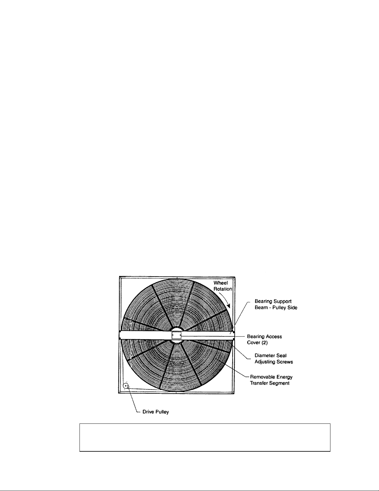
After the unit installation is complete, open the
cassette access door and determine that the energy
wheel rotates freely when turned by hand. Apply
power and observe that the wheel rotates at
approximately 30 RPM. If the wheel does not rotate
when power is applied, it may be necessary to readjust
the "diameter air seals".
AIR SEAL ADJUSTMENTS
Pile type air seals across both sides of the energy
wheel diameter are factory adjusted to provide close
clearance between the air seal and wheel. Racking of
the unit or cassette during installation, and / or
mounting of the unit on a non level support or in other
than the factory orientation can change seal
clearances. Tight seals will prevent rotation.
The initial set-up and servicing of the heatwheel is very
important to maintain proper operating efficiency and
building occupant comfort.
Normal maintenance requires periodic inspection of
filters, the cassette wheel, drive belts, air seals, wheel
drive motor and its electrical connections.
Wiring diagrams are provided with each motor. When
wired according to wiring diagram, motor rotates
clockwise when viewed from the shaft/pulley side.
By carefully reviewing the information within this
manual and following the instructions, the risk of
improper operation and/or component damage will be
minimized.
It is important that periodic maintenance be performed
to help assure trouble free operation. Should
equipment failure occur, contact a qualified service
organization with qualified, experienced HVAC
technicians to properly diagnose and repair this
equipment.
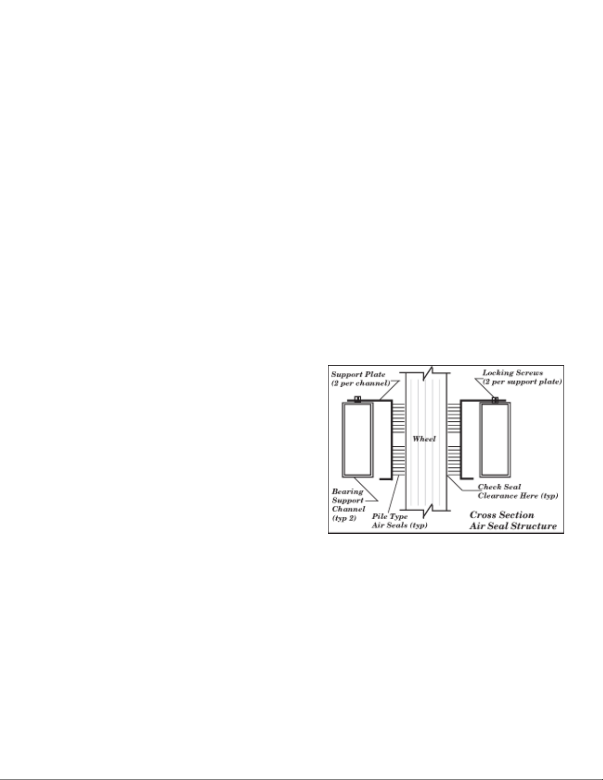
WHEEL-TO-AIRSEAL CLEARANCE
To check wheel-to-seal clearance; first disconnect
power to the unit. In some units the heatwheel
assembly can be pulled out from the cabinet to view
the airseals. On larger units, the heatwheel may be
accessible inside the walk-in cabinet.
A business card or two pieces of paper can be used as
a feeler gauge, (typically each .004" thick) by placing it
between the face of the wheel and the pile seal.
Using the paper, determine if a loose slip fit exist
between the pile seal and wheel when the wheel is
rotated by hand.
To adjust air seal clearance, loosen all seal plate
retaining screws holding the separate seal retaining
5
Page 6

plates to the bearing support channels and slide the
seal plates away from the wheel. Using the paper
feeler gauge, readjust and retighten one seal plate at a
time to provide slip fit clearance when the wheel is
rotated by hand.
Confirm that the wheel rotates freely. Apply power to
the unit and confirm rotation.
AIRFLOW BALANCING & CHECKING
High performance systems commonly have complex
air distribution and fan systems. Unqualified personnel
should not attempt to adjust fan operation, or air
circulation, as all systems have unique operating
characteristics. Professional air balance specialists
should be employed to establish actual operating
conditions, and to configure the air delivery system for
optimal performance.
Controls
A variety of controls and electrical accessories may be
provided with the equipment. Identify the controls on
each unit by consulting appropriate submittal, or order
documents, and operate according to the control
manufacturer’s instructions. If you cannot locate
installation, operation, or maintenance information for
the specific controls, then contact your sales
representative, or the control manufacturer for
assistance.
WARNING
Do not alter factory wiring. Deviation from the
supplied wiring diagram will void all warranties,
and may result in equipment damage or personal
injury. Contact the factory with wiring
discrepancies.
Lifting Hole Locations
Routine maintenance of the Energy Recovery
Cassettes includes periodic cleaning of the Energy
Recovery Wheel as well as inspection of the Air Seals
and Wheel Drive Components as follows:
Cleaning
The need for periodic cleaning of the energy recovery
wheel will be a function of operating schedule, climate
and contaminants in the indoor air being exhausted
and the outdoor air being supplied to the building.
The heatwheel is “self-cleaning” with respect to dry
particles due to its laminar flow characteristics. Smaller
particles pass through; larger particles land on the
surface and are blown clear as the flow direction is
reversed. Any material that builds up on the face of the
wheel can be removed with a brush or vacuum. The
primary need for cleaning is to remove oil based
aerosols that have condensed on energy transfer
surfaces.
ROUTINE MAINTENANCE & HANDLING
Handle cassettes with care. All cassettes should be
lifted by the bearing support beam. Holes are provided
on both sides of the bearing support beams to facilitate
rigging as shown in the following illustration.
A characteristic of all dry desiccants, such films can
close off micron sized pores at the surface of the
desiccant material, reducing the efficiency by which
the desiccant can adsorb and desorb moisture and
also build up so as to reduce airflow.
In a reasonably clean indoor environment such as a
school or office building, measurable reductions of
airflow or loss of sensible (temperature) effectiveness
may not occur for several years. Measurable changes
in latent energy (water vapor) transfer can occur in
shorter periods of time in applications such as
moderate occupant smoking or cooking facilities. In
applications experiencing unusually high levels of
occupant smoking or oil based aerosols such as
industrial applications involving the ventilation of
machine shop areas for example, annual washing of
energy transfer may be necessary to maintain latent
transfer efficiency. Proper cleaning of the energy
6
Page 7

recovery wheel will restore latent effectiveness to near
original performance.
To clean, gain access to the energy recovery wheel
and remove segments. Brush foreign material from the
face of the wheel. Wash the segments or small wheels
in a 5% solution of non-acid based coil cleaner or
alkaline detergent and warm water.
Soak in the solution until grease and tar deposits are
loosened (Note: some staining of the desiccant may
remain and is not harmful to performance). Before
removing, rapidly run finger across surface of segment
to separate polymer strips for better cleaning action.
Rinse dirty solution from segment and remove excess
water before reinstalling in wheel.
INSTALLATION CONSIDERATIONS
AAONAIRE® Energy recovery cassettes are
incorporated within the design of packaged units,
packaged air handlers and energy recovery
ventilators. In each case, it is recommended that the
following considerations be addressed:
Accessibility
The cassette and all its operative parts; i.e.: motor,
belt, pulley, bearings, seals and energy transfer
segments must be accessible for service and
maintenance. This design requires that adequate
clearance be provided outside the enclosure.
Where cassettes are permanently installed in a
cabinet, access to both sides of the cassette must be
provided.
CAUTION !
Do Not use acid based cleaners, aromatic
solvents, steam or temperatures in excess of
170°F; damage to the wheel my occur!
Air Seals
Four adjustable diameter seals are provided on each
cassette to minimize transfer of air between the
counter flowing airstreams.
To adjust diameter seals, loosen diameter seal
adjusting screws and back seals away from wheel
surface. Rotate wheel clockwise until two opposing
spokes are hidden behind the bearing support beam.
Using a folded piece of paper as a feeler gauge,
position paper between the wheel surface and
diameter seals.
Adjust seals towards wheel surface until a slight
friction on the feeler gauge (paper) is detected when
gauge is moved along the length of the spoke.
Retighten adjusting screws and recheck clearance
with “feeler” gauge.
Wheel Drive Components
The wheel drive motor bearings are pre-lubricated
and no further lubrication is necessary.
The wheel drive pulley is secured to the drive motor
shaft by a combination of either a key or D slot and set
screw.
The set screw is secured with removable locktite to
prevent loosening. Annually confirm set screw is
secure. The wheel drive belt is a urethane stretch
belt designed to provide constant tension through the
life of the belt. No adjustment is required. Inspect the
drive belt annually for proper tracking and tension. A
properly tensioned belt will turn the wheel immediately
after power is applied with no visible slippage during
start-up.
Orientation & Support
The Energy Recovery Cassette may be mounted in
any orientation. However, Care must be taken to
make certain that the cassette frame remains flat
and the bearing beams are not racked.
To verify, make certain that the distance between
wheel rim and bearing beam is the same at each end
of the bearing beam, to within 1/4 of an inch
(dimension A & B). This amount of racking can be
compensated for by adjusting the diameter seals.
If greater than 1/4 inch, racking must be corrected
to ensure that drive belt will not disengage from
wheel.
Avoid Racking Of Cassette Frame
7
Page 8

OPERATION
CAUTION !
Keep hands away from rotating wheel!!
Contact with rotating wheel can cause physical
injury.
Start Up Procedure
1. By hand, turn wheel clockwise (as viewed from the
pulley side), to verify wheel turns freely through 360º
rotation.
2. Before applying power to drive motor, confirm wheel
segments are fully engaged in wheel frame and
segment retainers are completely fastened.
(See Segment Installation Diagram).
3. With hands and objects away from moving parts,
activate unit and confirm wheel rotation. Wheel rotates
clockwise (as viewed from the pulley side).
4. If wheel has difficulty starting, turn power off and
inspect for excessive interference between the wheel
surface and each of the four (4) diameter seals. To
correct, loosen diameter seal adjusting screws and
back adjustable diameter seals away from surface of
wheel, apply power to confirm wheel is free to rotate,
then re-adjust and tighten hub and diameter seals, as
shown in hub seal adjustment diagram.
5. Start and stop wheel several times to confirm seal
adjustment and to confirm belt is tracking properly on
wheel rim (approximately 1/4” from outer edge of rim).
Diameter Seal Adjustment
Hub Seal Adjustment
8
Page 9

SERVICE
CAUTION !
Disconnect electrical power before servicing
energy recovery cassette.
Always keep hands away from bearing support
beam when installing or removing segments.
Failure to do so could result in severe injury to
fingers or hand.
Segment Installation & Replacement
Wheel segments are secured to the wheel frame by a
Segment Retainer which pivots on the wheel rim and
is held in place by a Segment Retaining Catch.
Segment Retainer
To install wheel segments follow steps one through
five below. Reverse procedure for segment removal.
1. Unlock two segment retainers (one on each side of
the selected segment opening.
2. With the embedded stiffener facing the motor side,
insert the nose of the segment between the hub
plates.
Segment Installation
3. Holding segment by the two outer corners, press the
segment towards the center of the wheel and inwards
against the spoke flanges. If hand pressure does not
fully seat the segment, insert the flat tip of a screw
driver between the wheel rim and outer corners of the
segment and apply downward force while guiding the
segment into place.
4. Close and latch each Segment Retainer under
Segment Retaining Catch.
5. Slowly rotate the wheel 180º. Install the second
segment opposite the first for counterbalance. Rotate
the two installed segments 90º to balance the wheel
while the third segment is installed. Rotate the wheel
180º again to install the fourth segment opposite the
third. Repeat this sequence with the remaining four
segments.
Wheel Drive Motor & Pulley Replacement
1. Disconnect power to wheel drive motor.
2. Remove belt from pulley and position temporarily
around wheel rim.
3. Loosen set screw in wheel drive pulley using a hex
head wrench and remove pulley from motor drive
shaft.
4. While supporting weight of drive motor in one hand,
loosen and remove (4) mounting bolts.
5. Install replacement motor with hardware kit
supplied.
6. Install pulley to dimension as shown and secure set
screw to drive shaft.
7. Stretch belt over pulley and engage in groove.
8. Follow start-up procedure.
9
Page 10

Belt Replacement
1. Obtain access to the pulley side bearing access
plate if bearing access plates are provided. Remove
two bearing access plate retaining screws and the
access plate.
2. Using hexagonal wrench, loosen set screw in
bearing locking collar. Using light hammer and drift (in
drift pin hole) tap collar in the direction of wheel
rotation to unlock collar. Remove collar.
3. Using socket wrench with extension, remove two
nuts which secure bearing housing to the bearing
support beam. Slide bearing from shaft. If not
removable by hand, use bearing puller.
4. Form a small loop of belt and pass it through the
hole in the bearing support beam. Grasp the belt at
the wheel hub and pull the entire belt down.
Note: Slight hand pressure against wheel rim will
lift weight of wheel from inner race of bearing to
assist bearing removal and installation.
CAUTION !
Protect hands and belt from possible sharp edges
of hole in Bearing Support Beam.
5. Loop the trailing end of the belt over the shaft (belt
is partially through the opening).
6. Reinstall the bearing onto the wheel shaft, being
careful to engage the two locating pins into the holes
in the bearing support beam. Secure the bearing with
two self locking nuts.
7. Install the belts around the wheel and pulley
according to the instructions provided with the belt.
8. Reinstall diameter seals or hub seal and tighten
retaining screws. Rotate wheel in clockwise direction
to determine that wheel rotates freely with slight drag
on seals.
9. Reinstall bearing locking collar. Rotate collar by
hand in the direction the wheel rotates (see label
provided on each cassette for wheel rotation).
10. Lock in position by tapping drift pin hole with
hammer and drift. Secure in position by tightening set
screw.
11. Reinstall Bearing Access Cover.
12. Apply power to wheel and ensure that the wheel
rotates freely without interference.
Belt Replacement
10
Page 11

DESIGN CONDITIONS & CONTROL STRATEGIES
Standard temperature control
The unit can be configured with normal air flows and
controls but still have the benefit of a large amount of
makeup air, better humidity control and lower
operating cost than a unit without a heat wheel. The
energy recovery unit operates in four (4) basic modes;
fan only; economizer; cooling and heating. Each of
these modes has specific functions as defined below.
Fan only mode: When the unit supply fan is started,
and there is no call for cooling or heating, the unit
economizer moves to its minimum position, the
heatwheel is activated and the heatwheel fan is
started. If the unit is equipped with heatwheel bypass
dampers, these are closed.
Economizer mode: With the unit supply fan in
operation and a call for cooling is made, if the outdoor
air temperature and humidity are below the enthalpy
setpoint, the heatwheel exhaust fan is activated, the
heatwheel is deactivated and the economizer
modulates to maintain the mixed air setpoint. If the unit
is equipped with heatwheel bypass dampers, these
are opened to accommodate the increase in outside
air volume.
Ventilation of Occupied Spaces
In Industrial Applications
General ventilation of occupied spaces in Industrial
facilities is an excellent application for energy
recovery. It can have many significant benefits
including: odor control, a better working environment
for employees, higher productivity, reduced risk from
exposure to volatile compounds and particulates in the
indoor air, improved humidity control (for process and
people) and reduced energy costs to condition the
ventilation air. General ventilation with energy recovery
is not a substitute for fume hood exhaust. The success
of the industrial application depends on proper design
and an understanding of the performance
characteristics of the enthalpy wheel.
Energy recovery wheels or enthalpy wheels have
some inherent exhaust air transfer due to the volume
of air carried by wheel rotation from one airstream to
the other. In addition, while wheels are highly resistant
to fouling due to the counter flowing airflow
arrangement, they can be plugged by large amounts of
semi-volatile compounds or aerosols, which are
allowed to impinge and/or condense on the wheel
surfaces. These characteristics affect the installation
and application as follows:
Cooling mode: With the unit supply fan in operation
and a call for cooling is made, if the outdoor air
temperature and humidity are above the enthalpy
setpoint, the economizer moves to its minimum
position and mechanical cooling is activated. The
heatwheel is activated and the heatwheel exhaust fan
is started. If the unit is equipped with heatwheel
bypass dampers, these are closed.
Heating mode: Upon a call for heat, the heating
function is activated, the supply fan is activated and
the economizer moves to its minimum position. The
heatwheel is activated and the heatwheel exhaust fan
is started. If the unit is equipped with heatwheel
bypass dampers, these are closed.
Notice that in all four (4) basic above modes, the
operation of the heatwheel is determined by the
position of the economizer. With the exception of unit
shutdown or a night setback mode, the heatwheel
exhaust fan is in operation.
When control systems are "by others", all of the above
modes of operation must be considered.
1. Use energy recovery for general dilution
ventilation of the occupied space, not for
recovering energy from dedicated, highly
concentrated or toxic exhaust.
Exhaust air transfer in the energy recovery system
results in a small amount of the exhaust air, typically
less than 5% for wheels operating in balanced flow,
returning to the space. This amount of exhaust air
transfer is appropriate to handling general exhaust in
an environment where continuous exhaust and supply
of outdoor air to the space achieves the required
dilution of contaminants. In space conditioning
applications, where the ventilation system is operating
to maintain acceptable indoor air quality, there should
not be contaminants in concentrations of concern. It is
not appropriate for recovering energy from highly
concentrated machine exhaust, such as hoods
installed on the print heads themselves. Even a small
amount of exhaust air transfer in this case can
increase contaminants and odors in the space. This air
is best exhausted directly outdoors and treated as may
be required by local code. If energy recovery is desired
in these environments, a “run around loop” approach is
suggested.
11
Page 12

2. Take “return” air (air to be exhausted after
recovering energy from it) from the occupied zone,
not from areas containing a high concentration of
dusts or aerosols such as the hood.
If necessary, provide supplemental filtration of the
return air at the inlets to the duct system. The goal of
the dilution ventilation is to preserve a healthful and
comfortable environment in the breathing zone. Supply
and return diffusers and grilles should be located to
achieve this end. Ceiling returns located directly above
machinery can provide additional benefits by directing
contaminants away from operators. In the industrial
application this air may contain high levels of aerosols,
which, once deposited and dried, would be difficult or
impossible to clean from ductwork, fans, dampers and
wheels. Therefore a filter of appropriate efficiency is
recommended to be installed at the inlet or “return
grille”.
Experience in industrial applications from small
facilities to large factories has shown that when these
two recommendations are observed, successful
application of energy recovery and its attendant
benefits is the result. On the other hand, ignoring
these common sense rules can result in reduced
satisfaction and/or equipment damage and a
maintenance challenge.
By contrast, in space conditioning applications, where
the ventilation system is operating to maintain
acceptable indoor air quality, there should be no
contaminants in concentrations of concern. Cross
leakage in the energy recovery system results in a
small amount of the exhaust air, typically less than 5%
for wheels operating in balanced flow, returning to the
space from which it came. This is not “contamination”
as it is often labeled. It is air that effectively never left
the space. The operating cost of moving this air is far
less than that required to operate purge sector.
This amount of cross leakage is appropriate to
handling bathroom exhaust in an environment where
continuous exhaust of the restroom achieves an air
quality on a par with the adjacent space. It is not
appropriate for recovering energy from toxic
environments, laboratory fume hoods, operating
rooms, etc. These are not recommended applications
for rotary based technology without a purge sector.
In fact, many of these environments should not
tolerate any cross leakage and as such should not
utilize rotary technology as even well designed purge
sectors do not achieve zero cross leak.
If energy recovery is required in these environments, a
“run around loop” approach is suggested.
Cross Leakage in Energy
Recovery Ventilation Systems
The issue of cross leakage in rotary wheel based
Energy Recovery used in space conditioning
applications is often misunderstood. As a result, many
systems are installed with purge sectors and the
additional fan capacity required to allow these sectors
to function when in fact they are unnecessary.
Understanding the rationale for the purge sector, its
history, its added first cost, and the associated
continuing cost of operation, the designer will rarely
specify purge.
A purge sector minimizes the carry over cross leakage
from exhaust into the supply airstream by shunting a
portion of the supply air back into the exhaust
airstream across the seal separating the exhaust and
supply. This is required for industrial process
applications where the exhaust contains contaminants
which would be detrimental to the process.
(Historically, heat wheels have been used primarily for
dehumidification and process heat recovery.) The
volume of air required for effective purge is listed at
10% to 20% of rated flow by manufacturers of
industrial process wheels. In addition to the cost of
providing the sector, the system must move 10 to 20%
more air than is required by the application in order to
purge.
The adjustable mechanical purge is capable of
reducing cross leakage to a fraction of one percent.
Nevertheless, purge should only be specified based on
an engineering evaluation of the cost to provide, the
cost to operate and the specific needs of the
application.
Moisture Transfer and Fungal Growth in Desiccant
Based Enthalpy Wheels
There is evidence that fungi germinate when water
condenses onto surfaces of air handling systems
where nutrients are present. Surfaces which remain
wet for a period of 12 to 24 hours allow fungi and mold
spores already present to “bloom”, resulting in a
potential IAQ problem.
This knowledge has led to questions of whether
desiccant energy recovery ventilation wheels, which in
fact transfer water from one airstream to another,
could provide a medium for growth of mold and fungi.
Such is not the case for AAONAIRE® technology, nor
has it been reported in the literature for other enthalpy
wheels.
In silica gel based desiccant wheels, the water
molecules are transferred by sorption, individually,
onto and off of the silica gel surface. Water is present
on the wheel in a molecular layer only. Condensation
does not occur. AAONAIRE® desiccant wheels
experience “dry” moisture transfer in that there is no
12
Page 13

bulk liquid water present which could support fungal
growth or dissolve other chemical species. The
transfer of water onto and off of the wheel’s desiccant
surfaces occurs in the vapor or gas phase. There are
no “wet” surfaces and liquid water does not enter the
air stream.
The sensible (non-desiccant coated) wheel can also
transfer water through the different mechanism of
condensation and re-evaporation, however; again,
there is no accumulation of water, unless the frosting
threshold is violated through misapplication of the
component. In this case, the water is in the form of
frost or ice which does not support fungal growth.
Sensible (uncoated) wheels from all manufacturers are
identical in this regard.
humidity. On the other hand, silica gel has superior
characteristics for the recovery of space conditioning
energy from exhaust air.)
The use of silica gel on rotary regenerators for energy
recovery ventilation applications involves a process
cycle where the silica gel is alternately exposed to
airstreams having nearly equal relative humidity
somewhere in the mid range of this curve (typically
between 40 and 60%). When the air stream with the
higher relative humidity passes over the silica gel
coated wheel, moisture is adsorbed from the air
stream into the silica gel. Then when the air stream
with the lower relative humidity contacts the silica gel,
moisture is desorbed (removed) from the silica gel and
put into the air stream.
Both moisture and nutrients are required to support
fungal growth. Therefore dirt accumulation on heat
wheels is of potential concern. It is also true that any
heat wheel can accumulate semi-volatile compounds
like tars and grease which are deposited on surfaces.
These surfaces can then become odor and
contaminant sources, in the same way that a filter or
any other element of an air handling system can
become a source of compounds accumulated over
time.
The heatwheel was designed to respond to these
issues over the life of the system by providing for
cleaning and maintenance with washable desiccant
surfaces, removable segments and easy to access
cassettes. Many aspects of this technology are
patented and are unique in the industry.
Silica Gel Desiccant
Silica gel is an inert, highly porous solid adsorbent
material that structurally resembles a rigid sponge. It
has a very large internal surface composed of myriad
microscopic cavities and a vast system of capillary
channels that provide pathways connecting the
internal microscopic cavities to the outside surface of
the “sponge”.
The characteristic curve for adsorption of water on
silica gel is shown in Figure 1 (page 13), as % weight
adsorbed versus relative humidity of the air stream in
contact with the silica gel. The amount of water
adsorbed rises almost linearly with increasing relative
humidity until RH reaches about 60%. It then plateaus
out at about 40% adsorbed as relative humidity
approaches 100%. (The curve for molecular sieves, by
contrast, rises rapidly to plateau at about 20%
adsorbed at 20% relative humidity. This helps to
explain why the molecular sieve is an excellent choice
for regenerated applications such as desiccant cooling
and dehumidification systems which are designed to
reduce processed airstreams to very low relative
In this ventilation energy recovery application, the
silica gel has all of its surface area covered with at
least a monomolecular layer of water because it has a
greater affinity for water than any other chemical
species. With all of the adsorption sites occupied by
water, the silica gel will not be able to transfer other
chemical species by adsorption and desorption in its
normal form. Species that are soluble in water could
become dissolved in the adsorbed water and then
released when the water is desorbed but this process
is limited by kinetics and does not present a very
efficient mechanism for contaminant transfer.
An example of this phenomenon is formaldehyde, a
gas which is very highly soluble in water.
In the early 1980’s when energy recovery ventilators
were being used to mitigate excessive formaldehyde
levels in mobile homes, concern was expressed by
some people that enthalpy type heat exchangers that
transferred moisture as well as heat might also
transfer excess amounts of formaldehyde gas due to
its high solubility in water. Accordingly, tests were
conducted by the Lawrence Berkeley Laboratories of
the U.S.D.O.E., on two enthalpy type exchangers to
determine whether this suspicion was justified. Results
were presented in ASHRAE paper No. CH85-03 No. 3
which reported that the rotary type enthalpy heat
exchanger transferred formaldehyde with only 3-6%
efficiency. They concluded that “formaldehyde transfer
between airstreams by processes other than air
leakage does not seriously compromise the
performance of these enthalpy exchangers”.
13
Page 14

ARI Performance Certification
The certified ratings program requires testing, rating
and independent verification of component
performance at standard conditions and rated flow.
Testing is in accordance with ASHRAE Standard 84.
Also, self-certification does not include the necessary
periodic verification tests and challenge procedures
provided by the industry certification program.
Specifications requiring ARI Certification in
accordance with the latest revision of ARI Standard
1060 provide the best assurance that components and
systems will perform as designed.
ARI certified ratings include very complete information,
some of it previously unavailable, to allow designers to
fully characterize thermal and airflow performance. In
addition to separate sensible, latent, and total
effectiveness at two airflows for both summer and
winter test conditions, the standard requires
information on pressure loss as well as air leakage.
Airxchange publishes ARI certified ratings for all
energy recovery ventilation components of their
manufacture in accordance with the requirements of
the ARI program. These ratings may be found on the
ARI website www.ari.org. Application ratings are
provided for the complete range of airflows and all
Airxchange cassettes bear the ARI Certification Seal.
With the ARI industry performance certification
program in place, engineers and building
owners/operators no longer need accept self
certification. It is important to point out that ratings
from non-participating manufacturers are difficult to
compare regardless of whether they are tested in
house or by an “independent” testing agency. This is in
part because the latent performance of a given unit
can change significantly when tested at different
outdoor air conditions and at less than rated airflows.
A product can be made to look better by testing it
“independently” at an easier condition. Lower relative
humidity (lower wet bulb) and less than rated airflow
improves the tested performance.
14
Page 15

15
Page 16

AAON, Inc.
)
2425 S. Yukon
Tulsa, Oklahoma 74107
Tel 918-583-2266
Fax 918-583-6094
Download this manual,
and others from:
www.aaon.com
It is the intent of AAON to provide accurate and current specification
information. However, in the interest of product improvement, AAON,
Inc. reserves the right to change pricing, specifications, and/or design
of its products without notice, obligation, or liability.
AAON is a registered trademark of AAON, Inc.
Effective August 2006
Supercedes August 1998
16
R86610 (Rev. A 8-06
 Loading...