

Page 1
M3 Series
Modular Indoor and Outdoor Air Handling Units
Installation, Operation
QUALIFIED INSTALLER
Improper installation, adjustment,
alteration, service or maintenance
can cause property damage,
personal injury or loss of life. Startup
and service must be performed by a
Factory Trained Service Technician.
A copy of this IOM should be kept
with the unit.
If the information in this manual is not
followed exactly, a fire or explosion
may result causing property damage,
personal injury or loss of life.
FOR YOUR SAFETY
Do not store or use gasoline or other
flammable vapors and liquids in the
vicinity of this or any other appliance.
& Maintenance
Page 2

Page 3

Table of Contents
Safety .............................................................................................................................................. 7
Unit Orientation ............................................................................................................................ 12
Model Number Nomenclature ...................................................................................................... 13
Base Model Feature Description ................................................................................................... 14
Supply Fan Module Feature Description ...................................................................................... 15
Cooling/Preheat Module Feature Description .............................................................................. 18
Heating Coil Module Description ................................................................................................. 21
Blank Module Feature Description ............................................................................................... 23
Filter Module Feature Description ................................................................................................ 24
Mixing Box/Economizer Module Feature Description ................................................................. 25
Discharge Module Feature Description ........................................................................................ 27
Control Panel Module Feature Description .................................................................................. 29
Exhaust Fan Module Feature Description ..................................................................................... 30
Energy Recovery Module Feature Description ............................................................................. 33
Return Fan Module Feature Description ....................................................................................... 35
General Description ...................................................................................................................... 37
Receiving ................................................................................................................................... 37
Storage ....................................................................................................................................... 38
Installation..................................................................................................................................... 38
Location/Clearances .................................................................................................................. 38
Rigging ...................................................................................................................................... 39
Module Location ....................................................................................................................... 39
Module Assembly ..................................................................................................................... 40
Module Disassembly ................................................................................................................. 44
Spring Isolator Adjustment ....................................................................................................... 44
Blower Wheels .......................................................................................................................... 45
Air Adjustment .......................................................................................................................... 45
Condensate Drains ..................................................................................................................... 46
Draw-Through P-Trap Example ............................................................................................ 48
Blow-Through P-Trap Example ............................................................................................ 52
Base Drains ............................................................................................................................... 54
External Control Panel .............................................................................................................. 54
Electrical .................................................................................................................................... 55
Foam Insulated Panel Cutting ................................................................................................ 55
Dampers and Actuators ............................................................................................................. 56
Duct System .............................................................................................................................. 57
Piping ........................................................................................................................................ 57
Operation....................................................................................................................................... 58
Startup Checklist ....................................................................................................................... 58
Procedures ................................................................................................................................. 59
Commissioning .......................................................................................................................... 59
Air Balancing ............................................................................................................................ 59
Water Balancing ........................................................................................................................ 60
Controls ..................................................................................................................................... 60
Maintenance .................................................................................................................................. 60
3
Page 4

Routine Maintenance ................................................................................................................. 60
Blower Assembly ...................................................................................................................... 60
Coils/Drain Pans ........................................................................................................................ 60
Winterizing Coils ...................................................................................................................... 61
Removing Coils ......................................................................................................................... 61
Doors/Panels .............................................................................................................................. 62
Outside Opening Door and Panel .............................................................................................. 62
Filters ......................................................................................................................................... 63
M3 Series Startup Form ................................................................................................................ 66
Maintenance Log .......................................................................................................................... 69
Literature Change History............................................................................................................. 70
R57350 · Rev. D · 140307
4
Page 5

Index of Tables and Figures
Tables:
Table 1 - Draw-Through Drain Trap Dimensions ........................................................................ 47
Table 2 - Blow-Through Drain Trap Dimensions......................................................................... 51
Table 3 - Flat Pleated Filters ......................................................................................................... 64
Table 4 - Angled Pleated Filters ................................................................................................... 64
Table 5 - Cartridge/Bag Filters ..................................................................................................... 64
Figures:
Figure 1 - Unit Orientation ........................................................................................................... 12
Figure 2 - Lockable Handle .......................................................................................................... 38
Figure 3 - Unit Lifting Example ................................................................................................... 39
Figure 4 - Unit Lifting Side View ................................................................................................. 39
Figure 5 - Module Location Example ........................................................................................... 40
Figure 6 - Moving Module with Pipes .......................................................................................... 41
Figure 7 - Neoprene Gasket .......................................................................................................... 41
Figure 8 - Module Connection ...................................................................................................... 41
Figure 9 - Module Connection Example ....................................................................................... 41
Figure 10 - Top View of Module Connection .............................................................................. 42
Figure 11 - Aligning Two Modules .............................................................................................. 42
Figure 12 - Aligning the Top of a Unit ......................................................................................... 42
Figure 13 - Lifting Lugs and Bolts ............................................................................................... 42
Figure 14 - Come-Along Putting Together Modules .................................................................... 42
Figure 15 - Pulling Sections Together .......................................................................................... 43
Figure 16 - Fastening Sections Together ...................................................................................... 43
Figure 17 - Attaching Splice ......................................................................................................... 43
Figure 18 - Attaching Corner Rail Cover ..................................................................................... 43
Figure 19 - Attaching Base Splice ................................................................................................ 44
Figure 20 - Blower Spring Isolator ............................................................................................... 44
Figure 21 - Spring Isolator Adjustment ........................................................................................ 45
Figure 22 - Supply Fan Banding ................................................................................................... 46
Figure 23 - Draw-Through Drain Trap ......................................................................................... 47
Figure 24 – Draw-Through Drain Pan Connection Locations ...................................................... 48
Figure 25 - Example Draw-Through AAONEcat32 Rating Sheet ............................................... 49
Figure 26 - Blow-Through Drain Trap ......................................................................................... 50
Figure 27 - Blow-Through Drain Pan Connection Locations ....................................................... 52
Figure 28 - Example Blow-Through AAONEcat32 Rating Sheet ................................................ 53
Figure 29 - External Control Panel ............................................................................................... 55
Figure 30 - Dampers ..................................................................................................................... 56
Figure 31 - Dampers and Actuator................................................................................................ 57
Figure 32 - Independently Controlled Dampers ........................................................................... 57
Figure 33 - Hydronic Coil Connections ........................................................................................ 58
5
Page 6

Figure 34 - Blower Rotation ......................................................................................................... 59
Figure 35 - Coil Removal ............................................................................................................. 62
Figure 36 - Access Door/Panel Removal ...................................................................................... 62
Figure 37 - Access Door ............................................................................................................... 63
Figure 38 - Cartridge/Bag Filter Layout Viewed from Upstream Side. ....................................... 65
6
Page 7
Safety
Attention should be paid to the following statements:
NOTE - Notes are intended to clarify the unit installation, operation and maintenance.
CAUTION - Caution statements are given to prevent actions that may result in
equipment damage, property damage, or personal injury.
WARNING - Warning statements are given to prevent actions that could result in
equipment damage, property damage, personal injury or death.
DANGER - Danger statements are given to prevent actions that will result in equipment
damage, property damage, severe personal injury or death.
ELECTRIC SHOCK, FIRE OR
EXPLOSION HAZARD
Failure to follow safety warnings
exactly could result in dangerous
operation, serious injury, death or
property damage.
Improper servicing could result in
dangerous operation, serious injury,
death or property damage.
Before servicing, disconnect all
electrical power to the unit. More
than one disconnect may be
provided.
When servicing controls, label all
wires prior to disconnecting.
Reconnect wires correctly.
Verify proper operation after
servicing. Secure all doors with
key-lock or nut and bolt.
Electric shock hazard. Before
servicing, disconnect all electrical
power to the unit, including remote
disconnects, to avoid shock hazard
or injury from rotating parts. Follow
proper Lockout-Tagout procedures.
FIRE, EXPLOSION OR CARBON
MONOXIDE POISONING HAZARD
Failure to replace proper controls
could result in fire, explosion or
carbon monoxide poisoning. Failure
to follow safety warnings exactly
could result in serious injury, death or
property damage. Do not store or use
gasoline or other flammable vapors
and liquids in the vicinity of this
appliance.
7
Page 8

VARIABLE FREQUENCY DRIVES
Do not leave VFDs unattended in
hand mode or manual bypass.
Damage to personnel or equipment
can occur if left unattended. When in
hand mode or manual bypass mode
VFDs will not respond to controls or
alarms.
GROUNDING REQUIRED
All field installed wiring must be
completed by qualified personnel.
Field installed wiring must comply
with NEC/CEC, local and state
electrical code requirements. Failure
to follow code requirements could
result in serious injury or death.
Provide proper unit ground in
accordance with these code
requirements.
During installation, testing, servicing
and troubleshooting of the equipment
it may be necessary to work with live
electrical components. Only a
qualified licensed electrician or
individual properly trained in handling
live electrical components shall
perform these tasks.
Standard NFPA-70E, an OSHA
regulation requiring an Arc Flash
Boundary to be field established and
marked for identification of where
appropriate Personal Protective
Equipment (PPE) be worn, should be
followed.
UNIT HANDLING
To prevent injury or death lifting
equipment capacity shall exceed unit
weight by an adequate safety factor.
Always test-lift unit not more than 24
inches high to verify proper center of
gravity lift point to avoid unit damage,
injury or death.
ROTATING COMPONENTS
Unit contains fans with moving parts
that can cause serious injury. Do not
open door containing fans until the
power to the unit has been
disconnected and fan wheel has
stopped rotating.
Electric motor over-current protection
and overload protection may be a
function of the Variable Frequency
Drive to which the motors are wired.
Never defeat the VFD motor overload
feature. The overload ampere setting
must not exceed 115% of the electric
motors FLA rating as shown on the
motor nameplate.
Failure to properly drain and vent
coils when not in use during freezing
temperature may result in coil and
equipment damage.
8
Page 9
Do not clean DX refrigerant coils with
hot water or steam. The use of hot
water or steam on refrigerant coils
will cause high pressure inside the
coil tubing and damage to the coil.
WATER PRESSURE
Prior to connection of condensing
water supply, verify water pressure is
less than maximum pressure shown
on unit nameplate. To prevent injury
or death due to instantaneous
release of high pressure water, relief
valves should be field supplied on
system water piping.
To prevent damage to the unit, do not
use acidic chemical coil cleaners. Do
not use alkaline chemical coil
cleaners with a pH value greater than
8.5, after mixing, without first using
an aluminum corrosion inhibitor in the
cleaning solution.
Do not use oxygen, acetylene or air
in place of refrigerant and dry
nitrogen for leak testing. A violent
explosion may result causing injury or
death.
Always use a pressure regulator,
valves and gauges to control
incoming pressures when pressure
testing a system. Excessive pressure
may cause line ruptures, equipment
damage or an explosion which may
result in injury or death.
Do not work in a closed area where
refrigerant or nitrogen gases may be
leaking. A sufficient quantity of
vapors may be present and cause
injury or death.
Rotation must be checked on all
MOTORS AND COMPRESSORS of
3 phase units at startup by a qualified
service technician. Scroll
compressors are directional and can
be damaged if rotated in the wrong
direction. Compressor rotation must
be checked using suction and
discharge gauges. Fan motor rotation
should be checked for proper
operation. Alterations should only be
made at the unit power connection
Do not weld or cut foam panel with
plasma cutters or a cutting torch –
When burnt the foam produces
dangerous fumes.
When steam cleaning coils, be sure
areas on both sides of the coil are
clear personnel.
9
Page 10
Some chemical coil cleaning
compounds are caustic or toxic. Use
these substances only in accordance
with the manufacturer’s usage
instructions. Failure to follow
instructions may result in equipment
damage, injury or death.
Door compartments containing
hazardous voltage or rotating parts
are equipped with door latches to
allow locks. Door latch are shipped
with nut and bolts requiring tooled
access. If you do not replace the
shipping hardware with a pad lock
always re-install the nut & bolt after
closing the door.
Check the shipping section weights
on the Bill of Lading to be sure they
can be lifted safely. Rigging should
be adjusted so that all sections are
lifted level.
Do not enter or reach into a fan
cabinet while the fan is still turning.
Never attempt to open an access
door or remove a panel while the unit
is running. Pressure in the unit can
cause excessive force against the
panel.
Never pressurize equipment over 8”
w.c – Equipment and property
damage, personal injury or loss of life
could result.
Ensure that sufficient dampers will be
open to provide air path before fan is
allowed to run.
Risk of injury from hot parts –
Disconnect all power, close all
isolation valves and allow equipment
to cool before servicing equipment
with hot water and steam heating
coils. Hot water will circulated even
after the power is off.
PVC (Polyvinyl Chloride) and CPVC
(Chlorinated Polyvinyl Chloride) are
vulnerable to attack by certain
chemicals. Polyolester (POE) oils
used with R-410A and other
refrigerants, even in trace amounts,
in a PVC or CPVC piping system will
result in stress cracking of the piping
and fittings and complete piping
system failure.
10
Page 11

HOT PARTS
Disconnect all power, close all
isolation valves and allow equipment
to cool before servicing equipment to
prevent serious injury. Equipment
may have multiple power supplies.
Electric resistance heating elements
and hot water or steam heating coils
may have automatic starts. Hot water
will circulate even after power is off.
1. Startup and service must be performed
by a Factory Trained Service
Technician.
2. The unit is for indoor or outdoor use.
See General Information section and unit
specifications for more unit information.
3. Every unit has a unique equipment
nameplate with electrical, operational,
and unit clearance specifications.
Always refer to the unit nameplate for
specific ratings unique to the model you
have purchased.
4. READ THE ENTIRE INSTALLATION,
OPERATION AND MAINTENANCE
MANUAL. OTHER IMPORTANT
SAFETY PRECAUTIONS ARE
PROVIDED THROUGHOUT THIS
MANUAL.
5. Keep this manual and all literature
safeguarded near or on the unit.
11
Page 12
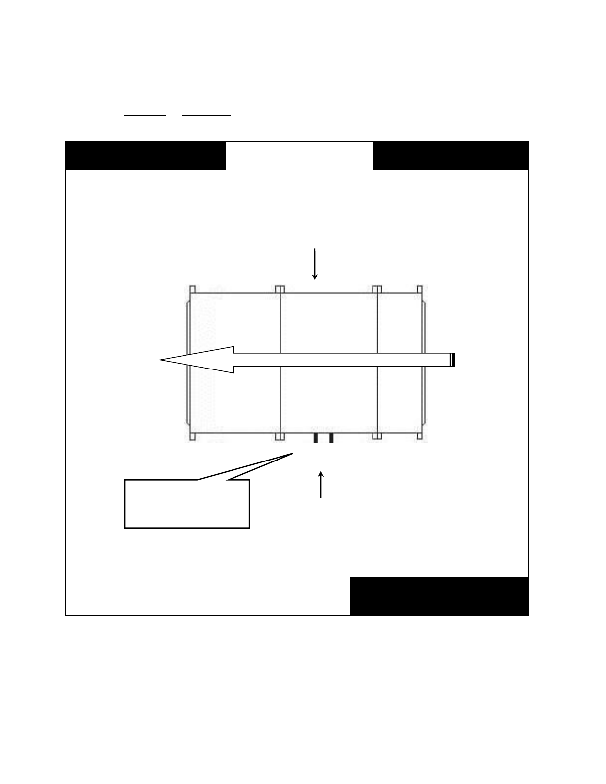
Unit Orientation
Consider the air flow to be
hitting the back of your head.
M3 Series
Top View
Return Air
Supply Air
Left Hand Side
Right Hand Side
Connections & service
access on left side for
left hand orientation
AIR FLOW
Filter
Coil
Supply Fan
Determine left hand or right hand orientation (connections):
12
Figure 1 - Unit Orientation
Page 13

Model Number Nomenclature
Base Model Number
Individual Module Model Numbers
Identifies the main unit features and options.
Identifies module configurations, features, and options.
MBA-101-0-00-0F0A0-000A0-0-0
FMB-102-0-00-B00C0-00000-0-0
CLA-103-A-00-CNCA0-00000-0-0
M3-0-094-134x119-3-A-A-A-0-A-0
:
BMA-104-A-00-00000-00000-0-0
SFA-105-0-AA-CPTB0-00000-0-0
DPA-106-0-00-D0000-0000C-M-0
Complete Model Number
The complete unit model number consists of
a base model number followed by a series of
individual module numbers. In the
individual module model number, the three
numbers after the three letter Module ID
indicate the position of the module in final
air handling unit assembly, increasing in
value from the return/outside air section to
the discharge air section. In the above
example, the cooling coil module, CLA103-A-00-CNCA0-00000-0-0, would be the
third module in the air handling unit.
13
Page 14

GEN UNIT TYPE UNIT SIZE CROSS
SECTION
VOLTAGE ASSEMBLY WIRING
ACCESSORIES
COROSSION
PROTECTION
BASE RAIL TYPE
M3
- 0 -
060
-
108
x
099
- 3 - B - A - B - C - B -
0
Base Model Feature Description
BASE MODEL
Series and Generation
M3
Type
0 = Indoor Unit
A = Outdoor Unit
Unit Size
032 = 32 ft2 Coil
039 = 39 ft2 Coil
045 = 45 ft2 Coil
054 = 54 ft2 Coil
060 = 60 ft2 Coil
067 = 67 ft2 Coil
074 = 74 ft2 Coil
083 = 83 ft2 Coil
094 = 94 ft2 Coil
Cross Section
092 x 066 = 92” x 66”
092 x 079 = 92” x 79”
092 x 089 = 92” x 89”
108 x 089 = 108” x 89”
108 x 099 = 108” x 89”
122 x 096 = 122” x 96”
134 x 096 = 134” x 96”
134 x 107 = 134” x 107”
134 x 119 = 134” x 119”
Voltage
2 = 230V/3Φ/60Hz
3 = 460V/3Φ/60Hz
4 = 575V/3Φ/60Hz
6 = 380-415V/3Φ/50Hz
8 = 208V/3Φ/60Hz
M3 Series Base Feature String Nomenclature
Assembly
A = Factory Assembled
B = Shipping Splits
Wiring
0 = No Wiring
A = Wiring, Motor Starters & Branch Fusing
Accessories
0 = None
A = 115V Outlet, Factory Wired (13Amp)
B = 115V Outlet, Field Wired (20 Amp)
Corrosion Protection
0 = No Paint
A = Interior Corrosion Protection
B = Exterior Corrosion Protection
C = Shipping Shrink Wrap
D = Options A + B
E = Options A + C
F = Options B + C
G = Options A + B + C
Base Rail
0 = 6” High
A = 8” High
B = 10” High
Type
0 = None
U= Special Exterior Paint and Special Pricing
Authorization
X = Special Pricing Authorization and Standard Paint
14
Page 15

Supply Fan Module Feature String Nomenclature
MODULE ID POSITION
CONNECTION
CTRL TYPE
CTRL MANU
BLWR
QUANTITY
BLWR
TYPE
BLWR HP
BLOWER
BLWR
ISOLATION FILT TYPE
FILT
ACCESSORY
POWER
SWITCH
CTRL
PANEL
MODULE
ACCESSORY
ACCESS TYPE
SFA
-
000
- 0 - 0 0 - C P H
G A - A C B 0 R - B -
0
Supply Fan Module Feature Description
SUPPLY FAN MODULE
Module ID
SFA = Supply Fan
SFB = Supply Fan with Flat Filter Bank
SFC = Supply Fan with External Control Panel
SFD = Supply Fan with Flat Filter Bank and External
Control Panel
Position
### = Level and Position of Module in Air Handling
Unit
Connections
0 = No End Wall
B = Air Leaving Side End Wall
CONTROLS
Type
0 = No Wiring
A = Terminal Strip, Branch Fusing
B = VAV Controller, Motor Starters, Branch Fusing
C = CAV Controller, Motor Starters, Branch Fusing
D = MUA Controller, Motor Starters, Branch Fusing
Manufacturer
0 = No Wiring
A = Terminal Strip
B = WattMaster
D = WattMaster with Specials
BLOWERS AND MOTORS
Quantity
0 = 1 Blower with ODP Motor
A = 2 Blowers with ODP Motors
B = 3 Blowers with ODP Motors
C = 4 Blowers with ODP Motors
D = 1 Blower with TEFC Motor
E = 2 Blowers with TEFC Motors
F = 3 Blowers with TEFC Motors
G = 4 Blowers with TEFC Motors
Blower Type
0 = Standard Efficiency
A = Premium Efficiency
B = Premium Eff with 1 VFD
C = Premium Eff with 1 VFD and Bypass
D = Premium Eff with Field Installed VFD
E = Premium Eff with 1 VFD Shipped Loose
F = Premium Eff with 2 VFDs
G = Premium Eff with 2 VFDs and Bypass
H = Premium Eff with 2 Field Installed VFDs
J = Premium Eff with 2 VFDs Shipped Loose
K = Premium Eff with 3 VFDs
L = Premium Eff with 3 VFDs and Bypass
M = Premium Eff with 3 Field Installed VFDs
N = Premium Eff with 3 VFDs Shipped Loose
P = Premium Eff with 4 VFDs
Q = Premium Eff with 4 VFDs and Bypass
R = Premium Eff with 4 Field Installed VFDs
S = Premium Eff with 4 VFDs Shipped Loose
Blower HP
0 = 1 hp, 1170 rpm
A = 2 hp, 1170 rpm
B = 3 hp, 1170 rpm
C = 5 hp, 1170 rpm
D = 7.5 hp, 1170 rpm
E = 10 hp, 1170 rpm
F = 15 hp, 1170 rpm
G = 20 hp, 1170 rpm
H = 25 hp, 1170 rpm
J = 30 hp, 1170 rpm
K = 40 hp, 1170 rpm
L = 50 hp, 1170 rpm
M = 1 hp, 1760 rpm
N = 2 hp, 1760 rpm
P = 3 hp, 1760 rpm
Q = 5 hp, 1760 rpm
R = 7.5 hp, 1760 rpm
S = 10 hp, 1760 rpm
T = 15 hp, 1760 rpm
U = 20 hp, 1760 rpm
V = 25 hp, 1760 rpm
W= 30 hp, 1760 rpm
Y = 40 hp, 1760 rpm
Z = 50 hp, 1760 rpm
1 = 60 hp, 1760 rpm
15
Page 16

Supply Fan Module Feature String Nomenclature
MODULE ID POSITION
CONNECTION
CTRL TYPE
CTRL MANU
BLWR
QUANTITY
BLWR
TYPE
BLWR HP
BLOWER
BLWR
ISOLATION FILT TYPE
FILT
ACCESSORY
POWER
SWITCH
CTRL
PANEL
MODULE
ACCESSORY
ACCESS TYPE
SFA
-
000
- 0 - 0 0 - C P H
G A - A C B 0
R - B - 0
Blower
0 = 24” Diameter
A = 27” Diameter
B = 30” Diameter
C = 33” Diameter
D = 36.5” Diameter
E = 42.5” Diameter
Blower Isolation
0 = Springs (Unhoused 1” Deflection)
A = Springs (Unhoused 2” Deflection)
B = Springs (Seismic 1” Deflection)
C = Springs (Seismic 2” Deflection)
D = Option 0 + Backdraft Dampers
E = Option A + Backdraft Dampers
F = Option B + Backdraft Dampers
G = Option C + Backdraft Dampers
Filter Type
0 = None
A = 2” Pleated, 30% Eff, MERV 8
B = 4” Pleated, 30” Eff, MERV 8
Filter Accessories
0 = None
A = Clogged Filter Switch
B = Magnehelic Gauge
C = Options A + B
D = Air Flow Measurement
E = Options A + D
F = Options B + D
G = Options A + B + D
Power Switch
0 = No Wiring
A = Power Block (No Power Switch)
B = 60 Amp Non-fused Disconnect Switch
C = 100 Amp Non-fused Disconnect Switch
D = 150 Amp Non-fused Disconnect Switch
E = 250 Amp Non-fused Disconnect Switch
F = 400 Amp Non-fused Disconnect Switch
G = 600 Amp Non-fused Disconnect Switch
H = 60 Amp Fused Disconnect Switch
J = 100 Amp Fused Disconnect Switch
K = 150 Amp Fused Disconnect Switch
L = 250 Amp Fused Disconnect Switch
M= 400 Amp Fused Disconnect Switch
N = 600 Amp Fused Disconnect Switch
Control Panel / Opening
0 = None
A = Left Control Panel
B = Right Control Panel
C = Left Discharge Opening
D = Options B + C
E = Right Discharge Opening
F = Options A + E
G = Top Discharge Opening
H = Options A + G
I = Options B + G
16
Page 17

Supply Fan Module Feature String Nomenclature
MODULE ID POSITION
CONNECTION
CTRL TYPE
CTRL MANU
BLWR
QUANTITY
BLWR
TYPE
BLWR HP
BLOWER
BLWR
ISOLATION FILT TYPE
FILT
ACCESSORY
POWER
SWITCH
CTRL
PANEL
MODULE
ACCESSORY
ACCESS TYPE
SFA
-
000
- 0 - 0 0 - C P H G A - A C B
0
R - B - 0
Module Accessories
0 = None
A = Treadplate Floor
B = Base Drain
C = Marine Light
D = Door Window
F = Options A + B
G = Options A + C
H = Options A + D
J = Options B + C
K = Options B + D
L = Options C + D
P = Options A + B + C
Q = Options A + B + D
R = Options A + C + D
S = Options B + C + D
U = Options A + B + C + D
Access
0 = Left Door, No Drain
A = Right Door, No Drain
B = Both Doors, No Drain
C = Left Door, Left Drain
D = Left Door, Right Drain
E = Left Door, Both Drains
F = Right Door, Left Drain
G = Right Door, Right Drain
H = Right Door, Both Drains
J = Both Doors, Left Drain
K = Both Doors, Right Drain
L = Both Doors, Both Drains
Type
0 = Standard
A = Stainless Steel Interior
B = Stainless Steel Exterior
C = Options A + B
X = Special Pricing Authorization
Y = Options A + X
Z = Options B + X
1 = Options A + B + X
17
Page 18

Cooling/Preheat Coil Module Feature String Nomenclature
MODULE ID POSITION AIRFLOW BLANK
BLANK COOLING
ROWS
FPI
CKTING
COATING
ACCESSORIES
PREHEAT
ROWS
FPI
TYPE
COATING
MODULE
ACCESSORY
ACCESS TYPE
CLD
-
000
- A - 0 0 - A
A
0 0 A - C A C 0 G - B - 0
Cooling/Preheat Module Feature Description
COOLING/PREHEAT MODULE
Module ID
CLA = Chilled Water Coils, External Connection,
Standard Drain Pan (30.5”)
CLC = Chilled Water Coils, Hydronic Preheat,
External Connection, Standard Drain Pan (30.5”)
CLD = DX Coils
CLE = DX Coils, Hot Gas Reheat
CLF = DX Coils, Hydronic Preheat
CLG = DX Coils, Hot Gas Reheat, Hydronic Preheat
CLH = Chilled Water Coils, External Connection,
Short Drain Pan (9”)
CLJ = Chilled Water Coils, Hydronic Preheat,
External Connection, Short Drain Pan (9”)
Position
### = Level and Position of Module in Air Handling
Unit
Compartment Pressurization
0 = Blow-Through, No End Wall
A = Draw-Through, No End Wall
B = Blow-Through, Air Leaving Side End Wall
Blank
00 = Standard
COOLING COIL
Rows
0 = 4 Rows, 1/2” Tubes, 50/50 Split
A = 6 Rows, 1/2” Tubes, 50/50 Split
B = 8 Rows, 1/2” Tubes, 50/50 Split
C = 4 Rows, 5/8” Tubes, 50/50 Split
D = 6 Rows, 5/8” Tubes, 50/50 Split
E = 8 Rows, 5/8” Tubes, 50/50 Split
FPI
0 = 8 FPI, 0.0060” Fin Thick, 0.017” Tube Wall
A = 10 FPI, 0.0060” Fin Thick, 0.017” Tube Wall
B = 12 FPI, 0.0060” Fin Thick, 0.017” Tube Wall
C = 8 FPI, 0.0075” Fin Thick, 0.017” Tube Wall
D = 10 FPI, 0.0075” Fin Thick, 0.017” Tube Wall
E = 12 FPI, 0.0075” Fin Thick, 0.017” Tube Wall
F = 8 FPI, 0.0100” Fin Thick, 0.017” Tube Wall
G = 10 FPI, 0.0100” Fin Thick, 0.017” Tube Wall
H = 12 FPI, 0.0100” Fin Thick, 0.017” Tube Wall
J = 8 FPI, 0.0060” Fin Thick, 0.025” Tube Wall
K = 10 FPI, 0.0060” Fin Thick, 0.025” Tube Wall
L = 12 FPI, 0.0060” Fin Thick, 0.025” Tube Wall
M = 8 FPI, 0.0075” Fin Thick, 0.025” Tube Wall
N = 10 FPI, 0.0075” Fin Thick, 0.025” Tube Wall
P = 12 FPI, 0.0075” Fin Thick, 0.025” Tube Wall
Q = 8 FPI, 0.0100” Fin Thick, 0.025” Tube Wall
R = 10 FPI, 0.0100” Fin Thick, 0.025” Tube Wall
S = 12 FPI, 0.0100” Fin Thick, 0.025” Tube Wall
T = 8 FPI, 0.0060” Fin Thick, 0.035” Tube Wall
U = 10 FPI, 0.0060” Fin Thick, 0.035” Tube Wall
V = 12 FPI, 0.0060” Fin Thick, 0.035” Tube Wall
W = 8 FPI, 0.0075” Fin Thick, 0.035” Tube Wall
Y = 10 FPI, 0.0075” Fin Thick, 0.035” Tube Wall
Z = 12 FPI, 0.0075” Fin Thick, 0.035” Tube Wall
1 = 8 FPI, 0.0100” Fin Thick, 0.035” Tube Wall
2 = 10 FPI, 0.0100” Fin Thick, 0.035” Tube Wall
3 = 12 FPI, 0.0100” Fin Thick, 0.035” Tube Wall
18
Page 19

Cooling/Preheat Coil Module Feature String Nomenclature
MODULE ID POSITION AIRFLOW BLANK
BLANK COOLING
ROWS
FPI
CKTING
COATING
ACCESSORIES
PREHEAT
ROWS
FPI
TYPE
COATING
MODULE
ACCESSORY
ACCESS TYPE
CLD
-
000
- A - 0 0 - A
A
0 0 A - C
A
C 0 G - B - 0
Circuiting
0 = Full Serpentine
A = Half Serpentine
B = 1 1/2 Serpentine
C = Double Serpentine
D = DX Single Systems
E = DX Two Interlaced Systems
Coating
0 = Galvanized Coil Casings
A = Polymer E-Coated Coils
B = Stainless Steel Coil Casings
C = Stainless Steel Coil Casings, Copper Fins
Accessories
0 = None
A = UV Lights
B = 2” Pleated Filters, 30% Eff, MERV 8, Coil Inlet
C = 4” Pleated Filters, 30% Eff, MERV 8, Coil Inlet
D = Options A + B
E = Options A + C
PREHEAT COIL
Rows
0 = No Preheat Coil
A = 1 Rows, 1/2” Tubes
B = 2 Rows, 1/2” Tubes
C = 1 Rows, 5/8” Tubes
D = 2 Rows, 5/8” Tubes
FPI
0 = No Preheat Coil
A = 8 FPI, 0.0060” Fin Thick, 0.017” Tube Wall
B = 10 FPI, 0.0060” Fin Thick, 0.017” Tube Wall
C = 12 FPI, 0.0060” Fin Thick, 0.017” Tube Wall
D = 8 FPI, 0.0075” Fin Thick, 0.017” Tube Wall
E = 10 FPI, 0.0075” Fin Thick, 0.017” Tube Wall
F = 12 FPI, 0.0075” Fin Thick, 0.017” Tube Wall
G = 8 FPI, 0.0100” Fin Thick, 0.017” Tube Wall
H = 10 FPI, 0.0100” Fin Thick, 0.017” Tube Wall
J = 12 FPI, 0.0100” Fin Thick, 0.017” Tube Wall
K = 8 FPI, 0.0060” Fin Thick, 0.025” Tube Wall
L = 10 FPI, 0.0060” Fin Thick, 0.025” Tube Wall
M = 12 FPI, 0.0060” Fin Thick, 0.025” Tube Wall
N = 8 FPI, 0.0075” Fin Thick, 0.025” Tube Wall
P = 10 FPI, 0.0075” Fin Thick, 0.025” Tube Wall
Q = 12 FPI, 0.0075” Fin Thick, 0.025” Tube Wall
R = 8 FPI, 0.0100” Fin Thick, 0.025” Tube Wall
S = 10 FPI, 0.0100” Fin Thick, 0.025” Tube Wall
T = 12 FPI, 0.0100” Fin Thick, 0.025” Tube Wall
U = 8 FPI, 0.0060” Fin Thick, 0.035” Tube Wall
V = 10 FPI, 0.0060” Fin Thick, 0.035” Tube Wall
W = 12 FPI, 0.0060” Fin Thick, 0.035” Tube Wall
Y = 8 FPI, 0.0075” Fin Thick, 0.035” Tube Wall
Z = 10 FPI, 0.0075” Fin Thick, 0.035” Tube Wall
1 = 12 FPI, 0.0075” Fin Thick, 0.035” Tube Wall
2 = 8 FPI, 0.0100” Fin Thick, 0.035” Tube Wall
3 = 10 FPI, 0.0100” Fin Thick, 0.035” Tube Wall
4 = 12 FPI, 0.0100” Fin Thick, 0.035” Tube Wall
19
Page 20

Cooling/Preheat Coil Module Feature String Nomenclature
MODULE ID POSITION AIRFLOW BLANK
BLANK COOLING
ROWS
FPI
CKTING
COATING
ACCESSORIES
PREHEAT
ROWS
FPI
TYPE
COATING
MODULE
ACCESSORY
ACCESS TYPE
CLD
-
000
- A - 0 0 - A A 0 0 A - C
A
C 0 G - B - 0
Preheat Coil Type
0 = No Preheat Coil
A = Hot Water, Full Serpentine (2 Rows Only)
B = Hot Water, Half Serpentine
C = Hot Water, Quarter Serpentine
D = Steam Distributing
Coating
0 = No Preheat Coil
A = Galvanized Coil Casing
B = Polymer E-Coated Coil
C = Stainless Steel Coil Casing
D = Stainless Steel Coil Casing, Copper Fins
Module Accessories
0 = None
A = Marine Light
B = Door Window
C = Options A + B
Access
0 = Left Door, Left Drain, Left Coil Connections
A = Left Door, Left Drain, Right Coil Connections
B = Left Door, Right Drain, Left Coil Connections
C = Left Door, Right Drain, Right Coil Connections
D = Left Door, Both Drains, Left Coil Connections
E = Left Door, Both Drains, Right Coil Connections
F = Right Door, Left Drain, Left Coil Connections
G = Right Door, Left Drain, Right Coil Connections
H = Right Door, Right Drain, Left Coil Connections
J = Right Door, Right Drain, Right Coil Connections
K = Right Door, Both Drains, Left Coil Connections
L = Right Door, Both Drains, Right Coil Connections
M = Both Doors, Left Drain, Left Coil Connections
N = Both Doors, Left Drain, Right Coil Connections
P = Both Doors, Right Drain, Left Coil Connections
Q = Both Doors, Right Drain, Right Coil Connection
R = Both Doors, Both Drains, Left Coil Connections
S = Both Doors, Both Drains, Right Coil Connections
Type
0 = Standard
A = Stainless Steel Interior
B = Stainless Steel Exterior
C = Options A + B
X = Special Pricing Authorization
Y = Options A + X
Z = Options B + X
1 = Options A + B + X
20
Page 21

Heating Coil Module Feature String Nomenclature
MODULE ID POSITION AIRFLOW ELEC HEAT
CAPACITY
STAGING
HEAT COIL
SIZE
ROWS
FPI
TYPE
COATING BLANK
BLANK
BLANK
BLANK
MODULE
ACCESSORY
ACCESS TYPE
HCD
-
000
- A - H E - B
B
C A A - 0 0 0 0 0 - B - 0
Heating Coil Module Description
HEATING COIL MODULE
Module ID
HCA = Hot Water Coil, External Connections
HCB = Steam Coil, External Connections
HCC = Electric Heat
HCD = Hot Water Coil with Internal Face and
Bypass Dampers
HCE = Hot Water Coil with External Face and
Bypass Dampers
HCF = Integral Face and Bypass Hot Water Coil
HCG = Steam Coil with Internal Face and Bypass
Dampers
HCH = Steam Coil with External Face and Bypass
Dampers
HCJ = Integral Face and Bypass Steam Coil
Position
### = Level and Position of Module in Air Handling
Unit
Compartment Pressurization
0 = Blow-Through
A = Draw-Through
ELECTRIC HEAT
Capacity
0 = No Electric Heat
A = 40 kW
B = 80 kW
C = 120 kW
D = 160 kW
E = 200 kW
F = 240 kW
G = 280 kW
H = 320 kW
J = 360 kW
K = 400 kW
L = 440 kW
M = 480 kW
Staging
0 = No Electric Heat
A = 2 Stage
B = 3 Stage
C = 4 Stage
D = 6 Stage
E = 8 Stage
F = 12 Stage
G = SCR Controlled - Potentiometer
H = SCR Controlled - 0-10VDC External Control
HEATING COIL
Size
0 = No Heating Coil
A = Size A
B = Size B
C = Size C
D = Size D
Rows
0 = No Heating Coil
A = 1 Row, 1/2” Tubes
B = 2 Rows, 1/2” Tubes
C = 1 Row, 5/8” Tubes
D = 2 Rows, 5/8” Tubes
21
Page 22

Heating Coil Module Feature String Nomenclature
MODULE ID POSITION AIRFLOW ELEC HEAT
CAPACITY
STAGING
HEAT COIL
SIZE
ROWS
FPI
TYPE
COATING BLANK
BLANK
BLANK
BLANK
MODULE
ACCESSORY
ACCESS TYPE
HCD
-
000
- A - H E - B
B
C A A - 0 0 0 0 0 - B - 0
FPI
0 = No Heating Coil
A = 8 FPI, 0.0060” Fin Thick, 0.017” Tube Wall
B = 10 FPI, 0.0060” Fin Thick, 0.017” Tube Wall
C = 12 FPI, 0.0060” Fin Thick, 0.017” Tube Wall
D = 8 FPI, 0.0075” Fin Thick, 0.017” Tube Wall
E = 10 FPI, 0.0075” Fin Thick, 0.017” Tube Wall
F = 12 FPI, 0.0075” Fin Thick, 0.017” Tube Wall
G = 8 FPI, 0.0100” Fin Thick, 0.017” Tube Wall
H = 10 FPI, 0.0100” Fin Thick, 0.017” Tube Wall
J = 12 FPI, 0.0100” Fin Thick, 0.017” Tube Wall
K = 8 FPI, 0.0060” Fin Thick, 0.025” Tube Wall
L = 10 FPI, 0.0060” Fin Thick, 0.025” Tube Wall
M = 12 FPI, 0.0060” Fin Thick, 0.025” Tube Wall
N = 8 FPI, 0.0075” Fin Thick, 0.025” Tube Wall
P = 10 FPI, 0.0075” Fin Thick, 0.025” Tube Wall
Q = 12 FPI, 0.0075” Fin Thick, 0.025” Tube Wall
R = 8 FPI, 0.0100” Fin Thick, 0.025” Tube Wall
S = 10 FPI, 0.0100” Fin Thick, 0.025” Tube Wall
T = 12 FPI, 0.0100” Fin Thick, 0.025” Tube Wall
U = 8 FPI, 0.0060” Fin Thick, 0.035” Tube Wall
V = 10 FPI, 0.0060” Fin Thick, 0.035” Tube Wall
W = 12 FPI, 0.0060” Fin Thick, 0.035” Tube Wall
Y = 8 FPI, 0.0075” Fin Thick, 0.035” Tube Wall
Z = 10 FPI, 0.0075” Fin Thick, 0.035” Tube Wall
1 = 12 FPI, 0.0075” Fin Thick, 0.035” Tube Wall
2 = 8 FPI, 0.0100” Fin Thick, 0.035” Tube Wall
3 = 10 FPI, 0.0100” Fin Thick, 0.035” Tube Wall
4 = 12 FPI, 0.0100” Fin Thick, 0.035” Tube Wall
Type
0 = No Heating Coil
A = Hot Water, Full Serpentine (2 Rows Only)
B = Hot Water, Half Serpentine
C = Hot Water, Quarter Serpentine
D = Steam Distributing
Coating
0 = No Heating Coil
A = Galvanized Coil Casing
B = Polymer E-Coated Coil
C = Stainless Steel Coil Casing
D = Stainless Steel Coil Casing, Copper Fins
Blank
0000 = Standard
Module Accessories
0 = None
A = Heating Coil Drain Pan
Access
0 = No Drain, Left Coil Connections
A = No Drain, Right Coil Connections
B = Left Drain, Left Coil Connections
C = Left Drain, Right Coil Connections
D = Right Drain, Left Coil Connections
E = Right Drain, Right Coil Connections
F = Both Drain, Left Coil Connections
G = Both Drain, Right Coil Connections
H = No Drain, No Coil Connections
Type
0 = Standard
A = Stainless Steel Interior
B = Stainless Steel Exterior
C = Options A + B
X = Special Pricing Authorization
Y = Options A + X
Z = Options B + X
1 = Options A + B + X
22
Page 23

Blank Module Feature String Nomenclature
MODULE ID POSITION AIRFLOW BLANK
BLANK DRAIN PAN
BLANK
BLANK
BLANK
BLANK BLANK
BLANK
BLANK
BLANK
MODULE
ACCESSORY
ACCESS TYPE
BMC
-
000
- A - 0 0 - 0 0 0 0 0 - 0 0 0 0 Q - B - 0
Blank Module Feature Description
BLANK MODULE
Module ID
BMA = 2’ Access Section
BMB = 2.5’ Access Section
BMC = 3’ Access Section
BMD = 4’ Access Section
Position
### = Level and Position of Module in Air Handling
Unit
Compartment Pressurization
0 = Blow-Through, No End Wall
A = Draw-Through, No End Wall
B = Blow-Through, Air Leaving Side End Wall
Blank
00 = Standard
Drain Pan
0 = None
A = Stainless Steel Drain Pan
Blank
0 = None
Blank
0 = None
Blank
0 = None
Blank
0 = Standard
Blank
0000 = Standard
Module Accessories
0 = None
A = Treadplate Floor
B = Base Drain
C = Marine Light
D = Door Window
F = Options A + B
G = Options A + C
H = Options A + D
J = Options B + C
K = Options B + D
L = Options C + D
P = Options A + B + C
Q = Options A + B + D
R = Options A + C + D
S = Options B + C + D
U = Options A + B + C + D
Access
0 = Left Door, No Drain
A = Right Door, No Drain
B = Both Doors, No Drain
C = Left Door, Left Drain
D = Left Door, Right Drain
E = Left Door, Both Drains
F = Right Door, Left Drain
G = Right Door, Right Drain
H = Right Door, Both Drains
J = Both Doors, Left Drain
K = Both Doors, Right Drain
L = Both Doors, Both Drains
M = No Door, No Drain
N = No Door, Left Drain
P = No Door, Right Drain
Q = No Door, Both Drains
Type
0 = Standard
A = Stainless Steel Interior
B = Stainless Steel Exterior
C = Options A + B
X = Special Pricing Authorization
Y = Options A + X
Z = Options B + X
1 = Options A + B + X
23
Page 24

Filter Module Feature String Nomenclature
MODULE ID POSITION BLANK BLANK
BLANK PREFILTER
FINAL
FILTER
FINAL
FILTER EFF
ACCESSORIES
BLANK BLANK
BLANK
BLANK
BLANK
BLANK BLANK TYPE
FMA
-
000
- 0 - 0 0 - A B C A 0 - 0 0 0 0 0 - 0 - 0
Filter Module Feature Description
FILTER MODULE
Module ID
FMA = Flat Filter Bank
FMB = Angle Filter Bank
FMC = Flat Cartridge Filter Bank
FMD = Staggered Cartridge Filter Bank
FME = Bag Filter Bank
FMF = HEPA Filter Bank
Position
### = Level and Position of Module in Air Handling
Unit
Blank
0 = Standard
Blank
00 = Standard
Pre-filter
0 = None
A = 2” Pleated, 30% Eff, MERV 8
B = 4” Pleated, 30% Eff, MERV 8
Final Filter
0 = None
A = 4” Cartridge Filter
B = 12” Cartridge Filter
C = 30” Bag Filter
Final Filter Efficiency
0 = None
A = MERV 11 (65% Eff)
B = MERV 13 (85% Eff)
C = MERV 14 (95% Eff)
Accessories
0 = None
A = Clogged Filter Switch
B = Magnehelic Gauge
C = Options A + B
Blank
0 = Standard
Blank
00000 = Standard
Blank
0 = Standard
Type
0 = Standard
A = Stainless Steel Interior
B = Stainless Steel Exterior
C = Options A + B
X = Special Pricing Authorization
Y = Options A + X
Z = Options B + X
1 = Options A + B + X
24
Page 25

Mixing Box/Economizer Module Feature String Nomenclature
MODULE ID POSITION
CONNECTION
BLANK
BLANK OA LOC
RA LOC
EA LOC
ACTUATOR
TYPE
OPENING
ACCESSORY
FILTER
FILT
ACCESSORY
BLANK
BLANK
MODULE
ACCESSORY
ACCESS TYPE
MBA
-
000
- 0 - 0 0 - B B C A 0 - A B 0
0
Q - B - 0
Mixing Box/Economizer Module Feature Description
MIXING BOX/ECONOMIZER
MODULE
Module ID
MBA = Mixing Box (RA & OA Openings)
MBB = Mixing Box, Flat Filter Bank
MBC = Economizer Box (RA, EA, & OA Openings)
MBD = Economizer Box, Flat Filter Bank
Position
### = Level and Position of Module in Air Handling
Unit
Connections
0 = No End Wall
A = Air Entering End Wall
Blank
00 = Standard
Outside Air Location
0 = None
A = End
B = Bottom
C = Left
D = Right
E = Top
F = End, Dampers
G = Bottom, Dampers
H = Left, Dampers
J = Right, Dampers
K = Top, Dampers
Return Air Location
0 = None
A = End
B = Bottom
C = Left
D = Right
E = Top
F = End, Dampers
G = Bottom, Dampers
H = Left, Dampers
J = Right, Dampers
K = Top, Dampers
Exhaust Air Location
0 = None
A = End
B = Bottom
C = Left
D = Right
E = Top
F = End, Dampers
G = Bottom, Dampers
H = Left, Dampers
J = Right, Dampers
K = Top, Dampers
L = End, Barometric Relief Damper
M = Left, Barometric Relief Damper
N = Right, Barometric Relief Damper
0 = None
A = Standard Damper, No Actuator
B = Standard Damper, On/Off Actuator
C = Standard Damper, 0-10 VDC Actuator
Opening Accessories
0 = None
A = Burglar Bars
B = Outdoor Air Hood
C = Outdoor Air Louvers
D = Options A + B
D = Options A + C
Filter
0 = None
A = 2” Pleated, 30% Eff, MERV 8
B = 4” Pleated, 30% Eff, MERV 8
Filter Accessories
0 = None
A = Clogged Filter Switch
B = Magnehelic Gauge
C = Options A + B
Blank
00 = Standard
25
Page 26

Mixing Box/Economizer Module Feature String Nomenclature
MODULE ID POSITION
CONNECTION
BLANK
BLANK OA LOC
RA LOC
EA LOC
ACTUATOR
TYPE
OPENING
ACCESSORY
FILTER
FILT
ACCESSORY
BLANK
BLANK
MODULE
ACCESSORY
ACCESS TYPE
MBA
-
000
- 0 - 0 0 - B B C A 0 - A B 0
0
Q - B - 0
Module Accessories
0 = None
A = Treadplate Floor
B = Base Drain
C = Marine Light
D = Door Window
F = Options A + B
G = Options A + C
H = Options A + D
J = Options B + C
K = Options B + D
L = Options C + D
P = Options A + B + C
Q = Options A + B + D
R = Options A + C + D
S = Options B + C + D
U = Options A + B + C + D
Access
0 = Left Door, No Drain
A = Right Door, No Drain
B = Left and Right Doors, No Drain
C = Left Door, Left Drain
D = Left Door, Right Drain
E = Left Door, Both Drains
F = Right Door, Left Drain
G = Right Door, Right Drain
H = Right Door, Both Drains
J = Left and Right Doors, Left Drain
K = Left and Right Doors, Right Drain
L = Left and Right Doors, Both Drains
M = Left and End Doors, No Drain
N = Left and End Doors, Left Drain
P = Left and End Doors, Right Drain
Q = Left and End Doors, Both Drains
R = Right and End Doors, No Drain
S = Right and End Doors, Left Drain
T = Right and End Doors, Right Drain
U = Right and End Doors, Both Drains
V = End Door, No Drain
W = End Door, Left Drain
Y = End Door, Right Drain
Z = End Door Both Drains
Type
0 = Standard
A = Stainless Steel Interior
B = Stainless Steel Exterior
C = Options A + B
X = Special Pricing Authorization
Y = Options A + X
Z = Options B + X
1 = Options A + B + X
26
Page 27

Discharge Module Feature String Nomenclature
MODULE ID POSITION
CONNECTION
CTRL TYPE
CTRL MANU
DISCH
OPEN LOC
ACTUATOR
TYPE
OPENING
ACCESSORIES
BLANK
PWR SWITCH
BLANK
BLANK
BLANK
CTRL PANEL
MODULE
ACCESSORY
ACCESS TYPE
DPA
-
000
- 0 - A A - B A 0 0 B - 0 0 0 0 Q
- B -
0
Discharge Module Feature Description
DISCHARGE MODULE
Module ID
DPA = Discharge Plenum
DPB = Discharge Plenum with Control Panel
Position
### = Level and Position of Module in Air Handling
Unit
Connections
0 = No End Wall
A = Air Leaving Side End Wall
CONTROLS
Controls Type
0 = No Wiring
A = Terminal Strip, Branch Fusing
B = VAV Controller, Motor Starters, Branch Fusing
C = CAV Controller, Motor Starters, Branch Fusing
D = MUA Controller, Motor Starters, Branch Fusing
Controls Manufacturer
0 = No Wiring
A = Terminal Strip
B = WattMaster
D = WattMaster with Specials
Discharge Opening Location
0 = End
A = Bottom
B = Left
C = Right
D = Top
E = End, Dampers
F = Bottom, Dampers
G = Left, Dampers
H = Right, Dampers
J = Top, Dampers
Damper Actuator Type
0 = None
A = Standard Damper
B = Standard Damper, On/Off Actuator
C = Standard Damper, 0-10 VDC Actuator
Opening Aceessories
0 = None
A = Burglar Bars
Blank
0 = Standard
Power Switch
0 = No Wiring
A = Power Block (No Power Switch)
B = 60 Amp Non-fused Disconnect Switch
C = 100 Amp Non-fused Disconnect Switch
D = 150 Amp Non-fused Disconnect Switch
E = 250 Amp Non-fused Disconnect Switch
F = 400 Amp Non-fused Disconnect Switch
G = 600 Amp Non-fused Disconnect Switch
H = 60 Amp Fused Disconnect Switch
J = 100 Amp Fused Disconnect Switch
K = 150 Amp Fused Disconnect Switch
L = 250 Amp Fused Disconnect Switch
M= 400 Amp Fused Disconnect Switch
N = 600 Amp Fused Disconnect Switch
Blank
000 = Standard
Control Panel
0 = No Control Panel
A = Left Control Panel
B = Right Control Panel
C = Center Control Panel
Module Accessories
0 = None
A = Treadplate Floor
B = Base Drain
C = Marine Light
D = Door Window
F = Options A + B
G = Options A + C
H = Options A + D
J = Options B + C
K = Options B + D
L = Options C + D
P = Options A + B + C
Q = Options A + B + D
R = Options A + C + D
S = Options B + C + D
U = Options A + B + C + D
27
Page 28

Discharge Module Feature String Nomenclature
MODULE ID POSITION
CONNECTION
CTRL TYPE
CTRL MANU
DISCH
OPEN LOC
ACTUATOR
TYPE
OPENING
ACCESSORIES
BLANK
PWR SWITCH
BLANK
BLANK
BLANK
CTRL PANEL
MODULE
ACCESSORY
ACCESS TYPE
DPA
-
000
- 0 - A A - B A 0 0 B - 0 0 0 0 Q
- B -
0
Access
0 = Left Door, No Drain
A = Right Door, No Drain
B = Both Doors, No Drain
C = Left Door, Left Drain
D = Left Door, Right Drain
E = Left Door, Both Drains
F = Right Door, Left Drain
G = Right Door, Right Drain
H = Right Door, Both Drains
J = Both Doors, Left Drain
K = Both Doors, Right Drain
L = Both Doors, Both Drains
M = No Door, No Drain
Type
0 = Standard
A = Stainless Steel Interior
B = Stainless Steel Exterior
C = Options A + B
X = Special Pricing Authorization
Y = Options A + X
Z = Options B + X
1 = Options A + B + X
28
Page 29

Control Panel Module Feature String Nomenclature
MODULE ID POSITION AIRFLOW CTRL TYPE
CTRL MANU
BLANK
BLANK
BLANK
BLANK
PWR SWITCH
BLANK
BLANK
BLANK
CTRL PANEL
MODULE
ACCESSORY
ACCESS TYPE
CMB
-
000
- 0 - A A - 0 0 0 0 A - 0 0 0 0 Q - B - 0
Control Panel Module Feature Description
CONTROL PANEL MODULE
Module ID
CMA = 36” Access Selection
CMB = 48” Access Selection
CMC = 60” Access Selection
Position
### = Level and Position of Module in Air Handling
Unit
Compartment Pressurization
0 = Blow-Through
A = Draw-Through
CONTROLS
Controls Type
0 = No Wiring
A = Terminal Strip, Branch Fusing
B = VAV Controller, Motor Starters, Branch Fusing
C = CAV Controller, Motor Starters, Branch Fusing
D = MUA Controller, Motor Starters, Branch Fusing
Controls Manufacturer
0 = No Wiring
A = Terminal Strip
B = WattMaster
D = WattMaster with Specials
Blank
0000 = Standard
Power Switch
0 = No Wiring
A = Power Block (No Power Switch)
B = 60 Amp Non-fused Disconnect Switch
C = 100 Amp Non-fused Disconnect Switch
D = 150 Amp Non-fused Disconnect Switch
E = 250 Amp Non-fused Disconnect Switch
F = 400 Amp Non-fused Disconnect Switch
G = 600 Amp Non-fused Disconnect Switch
H = 60 Amp Fused Disconnect Switch
J = 100 Amp Fused Disconnect Switch
K = 150 Amp Fused Disconnect Switch
L = 250 Amp Fused Disconnect Switch
M= 400 Amp Fused Disconnect Switch
N = 600 Amp Fused Disconnect Switch
Blank
000 = Standard
Control Panel Location
0 = No Control Panel
A = Left Control Panel
B = Right Control Panel
Module Accessories
0 = None
A = Treadplate Floor
B = Base Drain
C = Marine Light
D = Door Window
F = Options A + B
G = Options A + C
H = Options A + D
J = Options B + C
K = Options B + D
L = Options C + D
P = Options A + B + C
Q = Options A + B + D
R = Options A + C + D
S = Options B + C + D
U = Options A + B + C + D
Access
0 = No Door, No Drain
C = Left Door, No Drain
D = Right Door, No Drain
E = Left Door, Left Drain
F = Right Door, Left Drain
G = Left Door, Right Drain
H = Right Door, Right Drain
Type
0 = Standard
A = Stainless Steel Interior
B = Stainless Steel Exterior
C = Options A + B
X = Special Pricing Authorization
Y = Options A + X
Z = Options B + X
1 = Options A + B + X
29
Page 30

Exhaust Fan Module Feature String Nomenclature
MODULE ID POSITION
CONNECTION
PREHEAT
TYPE
PREHEAT
SIZE BLWR
QUANTITY
BLWR
TYPE
BLWR HP
BLOWER
BLWR
ISOLATION OA FILTER
OA LOC
EA LOC
ACTUATOR
TYPE
MODULE
ACCESSORY
ACCESS TYPE
EFA
-
000
- A - A B - A B B
A A - B B E C R - 0 -
0
Exhaust Fan Module Feature Description
EXHAUST FAN MODULE
Module ID
EFA = Exhaust Fan
EFB = Exhaust Fan for Energy Recovery Wheel
Position
### = Level and Position of Module in Air Handling
Unit
Connections
0 = No Air Entering End Wall
A = Air Entering Side End Wall
PREHEAT COIL
Type
0 = No Preheat
A = Hot Water Preheat
B = Steam Preheat
Size
0 = None
A = Preheat Size A
B = Preheat Size B
C = Preheat Size C
D = Preheat Size D
BLOWERS AND MOTORS
Quantity
0 = 1 Blower with ODP Motor
A = 2 Blowers with ODP Motors
B = 3 Blowers with ODP Motors
C = 4 Blowers with ODP Motors
D = 1 Blower with TEFC Motor
E = 2 Blowers with TEFC Motors
F = 3 Blowers with TEFC Motors
G = 4 Blowers with TEFC Motors
Blower Type
0 = Standard Efficiency
A = Premium Efficiency
B = Premium Eff with 1 VFD
C = Premium Eff with 1 VFD and Bypass
D = Premium Eff with Field Installed VFD
E = Premium Eff with 1 VFD Shipped Loose
F = Premium Eff with 2 VFDs
G = Premium Eff with 2 VFDs and Bypass
H = Premium Eff with 2 Field Installed VFDs
J = Premium Eff with 2 VFDs Shipped Loose
K = Premium Eff with 3 VFDs
L = Premium Eff with 3 VFDs and Bypass
M = Premium Eff with 3 Field Installed VFDs
N = Premium Eff with 3 VFDs Shipped Loose
P = Premium Eff with 4 VFDs
Q = Premium Eff with 4 VFDs and Bypass
R = Premium Eff with 4 Field Installed VFDs
S = Premium Eff with 4 VFDs Shipped Loose
Blower HP
0 = 1 hp, 1170 rpm
A = 2 hp, 1170 rpm
B = 3 hp, 1170 rpm
C = 5 hp, 1170 rpm
D = 7.5 hp, 1170 rpm
E = 10 hp, 1170 rpm
F = 15 hp, 1170 rpm
G = 20 hp, 1170 rpm
H = 25 hp, 1170 rpm
J = 30 hp, 1170 rpm
K = 40 hp, 1170 rpm
L = 50 hp, 1170 rpm
M = 1 hp, 1760 rpm
N = 2 hp, 1760 rpm
P = 3 hp, 1760 rpm
Q = 5 hp, 1760 rpm
R = 7.5 hp, 1760 rpm
S = 10 hp, 1760 rpm
T = 15 hp, 1760 rpm
U = 20 hp, 1760 rpm
V = 25 hp, 1760 rpm
W= 30 hp, 1760 rpm
Y = 40 hp, 1760 rpm
Z = 50 hp, 1760 rpm
1 = 60 hp, 1760 rpm
30
Page 31

Exhaust Fan Module Feature String Nomenclature
MODULE ID POSITION
CONNECTION
PREHEAT
TYPE
PREHEAT
SIZE BLWR
QUANTITY
BLWR
TYPE
BLWR HP
BLOWER
BLWR
ISOLATION OA FILTER
OA LOC
EA LOC
ACTUATOR
TYPE
MODULE
ACCESSORY
ACCESS TYPE
EFA
-
000
- A - A B - A B B
A A - B B
E
C R - 0 -
0
Blower
0 = 24” Diameter
A = 27” Diameter
B = 30” Diameter
C = 33” Diameter
D = 36.5” Diameter
E = 42.5” Diameter
F = 36” Diameter, 3 Blade, 6W Prop
G = 42” Diameter, 4 Blade, 6W Prop
H = 42” Diameter, 6 Blade, 6W Prop
I = 48” Diameter, 6 Blade, 6W Prop
Blower Isolation
0 = None
A = Springs (Unhoused 1” Deflection)
B = Springs (Unhoused 2” Deflection)
C = Springs (Seismic 1” Deflection)
D = Springs (Seismic 2” Deflection)
E = Option 0 + Backdraft Dampers
F = Option A + Backdraft Dampers
G = Option B + Backdraft Dampers
H = Option C + Backdraft Dampers
Outside Air Filters
0 = None
A = 2” Pleated, 30% Eff, MERV 8
B = 4” Pleated, 30” Eff, MERV 8
C = Option A + Clogged Filter Switch
D = Option B + Clogged Filter Switch
E = Option A + Magnehelic Gauge
F = Option B + Magnehelic Gauge
G = Option A + Clogged Filter Switch + Magnehelic
Gauge
H = Option B + Clogged Filter Switch + Magnehelic
Gauge
Outside Air Location
0 = None
A = End
B = Left
C = Right
D = Left and Right
E = Top
F = End, Dampers
G = Left, Dampers
H = Right, Dampers
J = Left and Right, Dampers
K = Top, Dampers
L = End, Hood
M = Left, Hood
N = Right, Hood
P = Left and Right, Hood
Q = End, Dampers, Hood
R = Left, Dampers, Hood
S = Right, Dampers, Hood
T = Left and Right, Dampers, Hood
U = End, Louvers
V = Left, Louvers
W = Right, Louvers
Y = Left and Right, Louvers
Z = End, Dampers, Louvers
1 = Left, Dampers, Louvers
2 = Right, Dampers, Louvers
3 = Left and Right, Dampers, Louvers
Exhaust Air Location
A = End
B = Left
C = Right
D = Left and Right
E = End, Dampers
F = Left, Dampers
G = Right, Dampers
H = Left and Right, Dampers
J = End, Barometric Relief Damper
K = Left, Barometric Relief Damper
L = Right, Barometric Relief Damper
M = Left and Right, Barometric Relief Damper
31
Page 32

Energy Recovery Module Feature String Nomenclature
MODULE ID POSITION BLANK ERW TYPE
& QTY
ERW SIZE BLANK
BLANK
BLANK
BLANK
BLANK RA FILT
RA LOC
ERW
ACCESSORY
ACTUATOR
TYPE
MODULE
ACCESSORY
ACCESS TYPE
HRA
-
000
- 0 - A C - 0 0 0 0 0 - G A A A C
- D -
0
Damper Actuator Type
0 = None
A = Standard Damper
B = Standard Damper, On/Off Actuator
C = Standard Damper, 0-10 VDC Actuator
Module Accessories
0 = None
A = Treadplate Floor
B = Base Drain
C = Marine Light
D = Door Window
F = Options A + B
G = Options A + C
H = Options A + D
J = Options B + C
K = Options B + D
L = Options C + D
P = Options A + B + C
Q = Options A + B + D
R = Options A + C + D
S = Options B + C + D
U = Options A + B + C + D
Access
0 = Left Door, No Drain
A = Right Door, No Drain
B = Both Doors, No Drain
C = Left Door, Left Drain
D = Left Door, Right Drain
E = Left Door, Both Drains
F = Right Door, Left Drain
G = Right Door, Right Drain
H = Right Door, Both Drains
J = Both Doors, Left Drain
K = Both Doors, Right Drain
L = Both Doors, Both Drains
M = No Doors, No Drain
N = No Doors, Left Drain
P = No Doors, Right Drain
Q = No Doors, Both Drain
Type
0 = Standard
A = Stainless Steel Interior
B = Stainless Steel Exterior
C = Options A + B
X = Special Pricing Authorization
Y = Options A + X
Z = Options B + X
1 = Options A + B + X
32
Page 33

Energy Recovery Module Feature String Nomenclature
MODULE ID POSITION BLANK ERW TYPE
& QTY
ERW SIZE BLANK
BLANK
BLANK
BLANK
BLANK RA FILT
RA LOC
ERW
ACCESSORY
ACTUATOR
TYPE
MODULE
ACCESSORY
ACCESS TYPE
HRA
-
000
- 0 - A C - 0 0 0 0 0 - G A A A C
- D -
0
Energy Recovery Module Feature Description
ENERGY RECOVERY MODULE
Module ID
HRA = AAONAIRE Energy Recovery Wheel
Position
### = Level and Position of Module in Air Handling
Unit
Blank
0 = Standard
Energy Recovery Wheel Type and Quantity
0 = 1 Total Energy Recovery Wheel
A = 2 Total Energy Recovery Wheels
B = 1 Sensible Energy Recovery Wheel
C = 2 Sensible Energy Recovery Wheels
Energy Recovery Wheel Size
0 = 25” Wheel
A = 36” Wheel
B = 52” Wheel
C = 64” Wheel
D = 74” Wheel
E = 81” Wheel
F = 86” Wheel
G = 92” Wheel
H = 99” Wheel
J = 104” Wheel
K = 110” Wheel
Blank
00000 = Standard
Return Air Filters
0 = None
A = 2” Pleated, 30% Eff, MERV 8
B = 4” Pleated, 30” Eff, MERV 8
C = Option A + Clogged Filter Switch
D = Option B + Clogged Filter Switch
E = Option A + Magnehelic Gauge
F = Option B + Magnehelic Gauge
G = Option A + Clogged Filter Switch + Magnehelic
Gauge
H = Option B + Clogged Filter Switch + Magnehelic
Gauge
Return Air Opening Location
0 = None
A = Bottom
B = Left
C = Right
D = Bottom, Dampers
E = Left, Dampers
F = Right, Dampers
G = Bottom, Burglar Bars
H = Left, Burglar Bars
J = Bottom, Dampers
K = Bottom, Dampers, Burglar Bars
L = Left, Dampers, Burglar Bars
M = Right, Dampers, Burglar Bars
Energy Recovery Wheel Accessoris
0 = None
A = Energy Recovery Wheel Purge
C = Defrost Timer
D = Rotation Detector
G = Options A + C
H = Options A + D
N = Options C + D
U = Options A + C + D
Damper Actuator Type
0 = None
A = Standard Damper
B = Standard Damper, On/Off Actuator
C = Standard Damper, 0-10 VDC Actuator
Module Accessories
0 = None
A = Treadplate Floor
B = Base Drain
C = Marine Light
D = Door Window
F = Options A + B
G = Options A + C
H = Options A + D
J = Options B + C
K = Options B + D
L = Options C + D
P = Options A + B + C
Q = Options A + B + D
R = Options A + C + D
S = Options B + C + D
U = Options A + B + C + D
33
Page 34

Energy Recovery Module Feature String Nomenclature
MODULE ID POSITION BLANK ERW TYPE
& QTY
ERW SIZE BLANK
BLANK
BLANK
BLANK
BLANK RA FILT
RA LOC
ERW
ACCESSORY
ACTUATOR
TYPE
MODULE
ACCESSORY
ACCESS TYPE
HRA
-
000
- 0 - A C - 0 0 0 0 0 - G A A A C
- D -
0
Access
0 = Left Door, Left Drain
1 = Left Door, No Drain
2 = Right Door, No Drain
3 = Both Doors, No Drain
B = Left Door, Right Drain
D = Left Door, Both Drains
F = Right Door, Left Drain
H = Right Door, Right Drain
K = Right Door, Both Drain
M = Both Doors, Left Drain
P = Both Doors, Right Drain
R = Both Doors, Both Drains
Type
0 = Standard
A = Stainless Steel Interior
B = Stainless Steel Exterior
C = Options A + B
X = Special Pricing Authorization
Y = Options A + X
Z = Options B + X
1 = Options A + B + X
34
Page 35

Return Fan Module Feature String Nomenclature
MODULE ID POSITION
CONNECTION
BLANK
BLANK BLWR
QUANTITY
BLWR
TYPE
BLWR HP
BLOWER
BLWR
ISOLATION BLANK
BLANK
BLANK
CONNECTION
MODULE
ACCESSORY
ACCESS TYPE
RFA
-
000
- 0 - 0 0 - C P H D A
- 0 0 0 A R - B -
0
Return Fan Module Feature Description
RETURN FAN MODULE
Module ID
RFA = Return Fan Module
Position
### = Level and Position of Module in Air Handling
Unit
Connections
0 = No End Wall
A = Air Entering End Wall
Blank
0 = Standard
Blank
0 = Standard
BLOWERS AND MOTORS
Quantity
0 = 1 Blower with ODP Motor
A = 2 Blowers with ODP Motors
B = 3 Blowers with ODP Motors
C = 4 Blowers with ODP Motors
D = 1 Blower with TEFC Motor
E = 2 Blowers with TEFC Motors
F = 3 Blowers with TEFC Motors
G = 4 Blowers with TEFC Motors
Blower Type
0 = Standard Efficiency
A = Premium Efficiency
B = Premium Eff with 1 VFD
C = Premium Eff with 1 VFD and Bypass
D = Premium Eff with Field Installed VFD
E = Premium Eff with 1 VFD Shipped Loose
F = Premium Eff with 2 VFDs
G = Premium Eff with 2 VFDs and Bypass
H = Premium Eff with 2 Field Installed VFDs
J = Premium Eff with 2 VFDs Shipped Loose
K = Premium Eff with 3 VFDs
L = Premium Eff with 3 VFDs and Bypass
M = Premium Eff with 3 Field Installed VFDs
N = Premium Eff with 3 VFDs Shipped Loose
P = Premium Eff with 4 VFDs
Q = Premium Eff with 4 VFDs and Bypass
R = Premium Eff with 4 Field Installed VFDs
S = Premium Eff with 4 VFDs Shipped Loose
Blower HP
0 = 1 hp, 1170 rpm
A = 2 hp, 1170 rpm
B = 3 hp, 1170 rpm
C = 5 hp, 1170 rpm
D = 7.5 hp, 1170 rpm
E = 10 hp, 1170 rpm
F = 15 hp, 1170 rpm
G = 20 hp, 1170 rpm
H = 25 hp, 1170 rpm
J = 30 hp, 1170 rpm
K = 40 hp, 1170 rpm
L = 50 hp, 1170 rpm
M = 1 hp, 1760 rpm
N = 2 hp, 1760 rpm
P = 3 hp, 1760 rpm
Q = 5 hp, 1760 rpm
R = 7.5 hp, 1760 rpm
S = 10 hp, 1760 rpm
T = 15 hp, 1760 rpm
U = 20 hp, 1760 rpm
V = 25 hp, 1760 rpm
W= 30 hp, 1760 rpm
Y = 40 hp, 1760 rpm
Z = 50 hp, 1760 rpm
1 = 60 hp, 1760 rpm
Blower
0 = 24” Diameter
A = 27” Diameter
B = 30” Diameter
C = 33” Diameter
D = 36.5” Diameter
E = 42.5” Diameter
F = 36” Diameter, 3 Blade, 6W Prop
G = 42” Diameter, 4 Blade, 6W Prop
H = 42” Diameter, 6 Blade, 6W Prop
I = 48” Diameter, 6 Blade, 6W Prop
Blower Isolation
A = Springs (Unhoused 1” Deflection)
B = Springs (Unhoused 2” Deflection)
C = Springs (Seismic 1” Deflection)
D = Springs (Seismic 2” Deflection)
E = Option 0 + Backdraft Dampers
F = Option A + Backdraft Dampers
G = Option B + Backdraft Dampers
H = Option C + Backdraft Dampers
35
Page 36

Return Fan Module Feature String Nomenclature
MODULE ID POSITION
CONNECTION
BLANK
BLANK BLWR
QUANTITY
BLWR
TYPE
BLWR HP
BLOWER
BLWR
ISOLATION BLANK
BLANK
BLANK
CONNECTION
MODULE
ACCESSORY
ACCESS TYPE
RFA
-
000
- 0 - 0 0 - C P H D A
- 0 0 0 A R - B -
0
Blank
000 = Standard
Connection
0 = No End Wall
A = Air Entering End Wall
Module Accessories
0 = None
A = Treadplate Floor
B = Base Drain
C = Marine Light
D = Door Window
F = Options A + B
G = Options A + C
H = Options A + D
J = Options B + C
K = Options B + D
L = Options C + D
P = Options A + B + C
Q = Options A + B + D
R = Options A + C + D
S = Options B + C + D
U = Options A + B + C + D
Access
M = No Door, No Drain
N = No Door, Left Drain
P = No Door, Right Drain
Q = No Door, Both Drains
Type
0 = Standard
A = Stainless Steel Interior
B = Stainless Steel Exterior
C = Options A + B
X = Special Pricing Authorization
Y = Options A + X
Z = Options B + X
1 = Options A + B + X
36
Page 37
Improper installation, adjustment,
alteration, service or maintenance
can cause property damage,
personal injury or loss of life.
Installation and service must be
performed by a trained, qualified
installer. A copy of this IOM should
be kept with the unit.
These units must not be used as a
“construction heater” at anytime
during any phase of construction.
Very low return air temperatures,
harmful vapors, and misplacement of
the filters will damage the unit and its
efficiency.
This equipment is protected by a
standard limited warranty under the
condition that initial start up and
maintenance is performed according
to the instructions set forth in this
manual. This manual should be read
in its entirety prior to installation and
before performing any service or
maintenance work.
General Description
M3 Series modular air handling units have
been designed to maximize the versatility
and range of applications. This manual is
intended to be a guide to facilitate the
installation, startup, operation, and
maintenance of this product.
Any conflicting codes or regulations take
precedence over the information in this
manual. It is important that all installation
and service work be performed by qualified
professionals.
M3 Series modular air handling units are
designed for safe operation when installed,
operated, and maintained within design
specifications and the instructions set forth
in this manual. It is necessary to follow
these instructions to avoid personal injury or
damage to equipment or property during
equipment installation, operation, startup,
and maintenance.
Receiving
All shipments are FOB from the factory. It
is the responsibility of the receiving party to
inspect the equipment upon arrival. Units
should be inspected for damage that may
have occurred in transit. Please do not refuse
shipments!
Do the following upon receipt:
1. Assure that freight carrier is in
compliance with Bill of Lading
instructions.
2. Inspect delivery before signing Bill of
Lading.
If damage is found or items are missing:
1. Note on Bill of Lading immediately.
2. Call carrier immediately to file a freight
claim and to schedule an inspection.
3. Photograph damage if possible.
4. Do not move or discard damaged freight
packaging materials
5. After losses have been acknowledged by
the freight carrier, contact factory for a
repair or replacement part quote.
37
Page 38
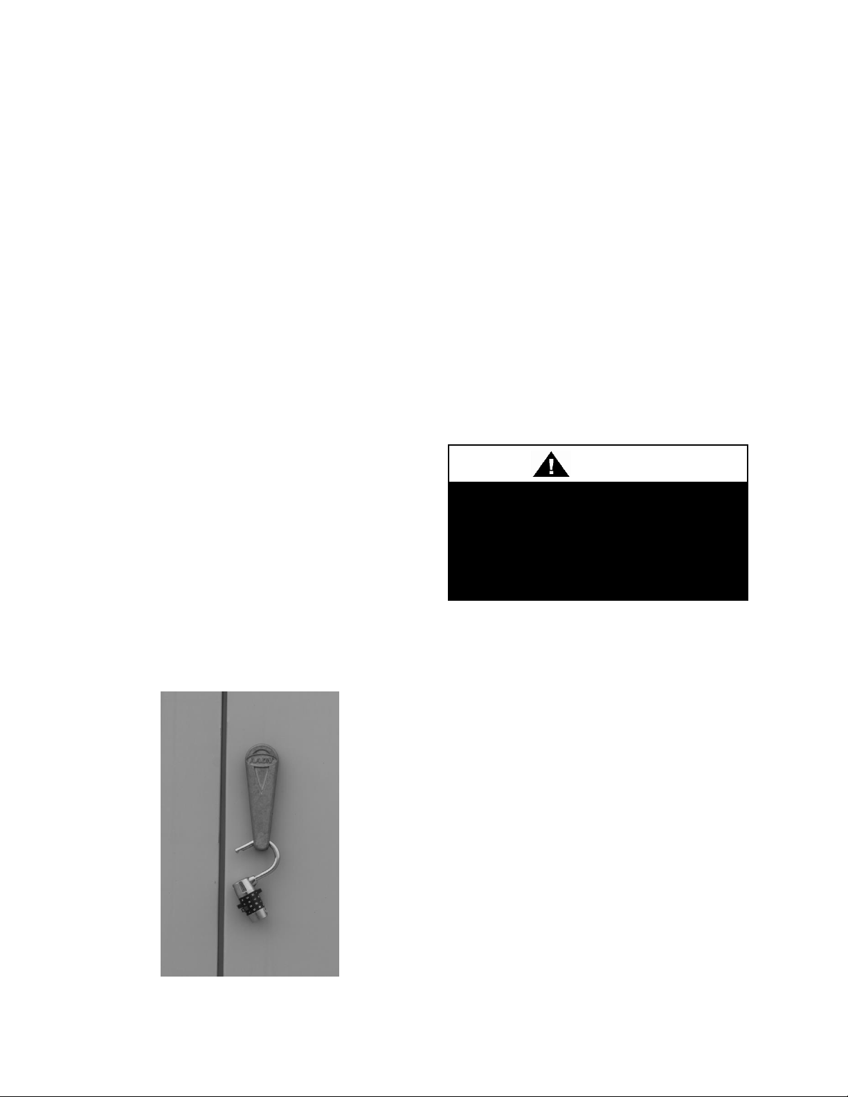
If the optional shrink wrap is selected
it should be left on units until placed
inside the building. Unprotected units
could develop corrosion if left
exposed to the environment.
6. With permission of freight carrier, order
parts and/or make repairs.
7. Stay in contact with freight carrier to
ensure payment of your claim.
Nameplate should be checked to ensure the
correct model sizes and voltages have been
received to match the job requirements.
If repairs must be made to damaged goods,
then the factory should be notified before
any repair action is taken in order to protect
the warranty. Certain equipment alteration,
repair, and manipulation of equipment
without the manufacturer’s consent may
void the product warranty. Contact the
AAON Warranty Department for assistance
with handling damaged goods, repairs, and
freight claims: (918) 382-6196.
Note: Upon receipt check shipment for
items that ship loose such as filters,
thermostats and remote sensors. Consult
order and shipment documentation to
identify potential loose-shipped items.
Loose-shipped items may have been placed
inside unit cabinet for security. Installers
and owners should secure all doors with
locks or nuts and bolts to prevent
unauthorized access.
Figure 2 - Lockable Handle
38
The warranty card must be completed in full
and returned to AAON not more than 3
months after unit is delivered.
Storage
Indoor units are not designed for outdoor
use or storage. Equipment should be
protected from environmental conditions
such as rain, snow, humidity, extreme
temperatures and corrosive chemicals.
If installation will not occur immediately
following delivery, then store the equipment
in a dry protected area away from
construction traffic, and in the proper
orientation with all internal packaging in
place. Secure all loose-shipped items.
Installation
AAON equipment has been designed for
quick and easy installation.
Location/Clearances
Unit should be installed on a flat, level and
rigid surface which is capable of supporting
the weight of the unit, including water in the
coils. It is important that the unit be installed
level for drain pan and coil drainage.
The unit should be located so that there is
sufficient clearance for accessing doors and
panels. A minimum clearance of one unit
width is recommended on one side for coil
removal.
Page 39

Check the shipping section weights
on the Bill of Lading to be sure they
can be lifted safely. Rigging should
be adjusted so that all sections are
lifted level.
Rigging
The unit should be lifted using all marked
lifting points. Spreader bars should be used
to prevent damage to the unit. They should
be at least 12 inches wider than the unit to
prevent damage. Be sure that the protruding
coil connections are not interfering with the
straps.
to prevent excess lateral force on the lifting
points.
All shipping covers should be left in place
until ductwork is ready to be connected or
shipping sections are ready to be joined.
Figure 3 - Unit Lifting Example
Only two lifting points on each side of the
unit should be connected to one spreader
bar, and the straps, chains or cables
connected to a single spreader bar should be
the same length. The angle of each strap
should be a minimum of 60° from horizontal
Figure 4 - Unit Lifting Side View
Module Location
Module location is identified by a three digit
number which is labeled on the access side
of the base rail. The last two digits in the
location number are an incremental number
for the position.
The numbering begins at the return air side
of the unit. Module 101 will always be the
bottom module at the return air end of the
unit.
39
Page 40

The unit tag number will also be displayed
on each module, so that each module can be
reattached to the correct unit.
Figure 5 - Module Location Example
Module Assembly
The following tools are suggested for
equipment assembly:
• Power drill with 5/16” socket
• Come-along (2)
• ½” wrench and socket
• Crowbar
• Phillips-head screwdriver
40
1. Move the section chosen to be installed
first, to the correct position. It is
recommended to start with the heaviest
section. If that is not possible then the first
section may need to be secured to prevent it
from moving when additional sections of the
unit are installed.
The modules can be moved by rolling them
on pipes. The pipes should be spaced a
maximum of one foot apart. See the
following figure.
Page 41

41
Figure 6 - Moving Module with Pipes
2. Remove module shipping covers. Check
to make sure neoprene gasket is installed on
downstream edge of each section. If any
neoprene gasket is damaged or missing it
should be repaired with 3/8” thick lowdurometer neoprene.
Figure 8 - Module Connection
4. Pull the two sections together using a
come-along attached to the lifting points on
the base rail.
Figure 7 - Neoprene Gasket
3. Correctly orient the second section and
move it close to the first, while aligning the
two sections. The split unit lifting lugs
should be removed once there is no longer a
need to lift the section.
Figure 9 - Module Connection Example
As the sections come together make sure the
integrated splice on the unit walls and roof
correctly overlap the walls and roof of the
adjoining module.
Page 42

Bolts
Lifting
Lug
The following figure displays a top view of
the correctly overlapping module sections
with integrated splice.
Figure 10 - Top View of Module
Connection
A crow-bar or similar tool can be used
through the lifting holes to line up the two
sections.
Figure 12 - Aligning the Top of a Unit
5. Secure the two sections together with
bolts in the holes surrounding the lifting
hole in the base rail.
Be sure to replace the lifting lugs on either
side of the two base rails before bolting
together.
Figure 11 - Aligning Two Modules
The top of the two sections can be aligned
by using a come-along diagonally across the
top of the unit.
42
Figure 13 - Lifting Lugs and Bolts
6. Pull the top of the two sections together
using a come-along attached to the lug
points in the top-corner rail.
Figure 14 - Come-Along Putting Together
Modules
Page 43

43
7. Pull sections together until exterior skins
meet.
Figure 15 - Pulling Sections Together
8. After ensuring that the dimensions are
correct, fasten sections together with selftapping screws (#10 HEX HEAD) on top
angle.
9. Attach integrated splice on walls and roof
to adjoining section with self-tapping screws
(#10 HEX HEAD)
Figure 17 - Attaching Splice
10. Attach corner rail cover with provided
.5” #10 flat head screws.
Figure 16 - Fastening Sections Together
Figure 18 - Attaching Corner Rail Cover
Page 44

Removing modules that are too small
could result in injury and damage to
equipment as the module could tip
over. All sections should have a
minimum length at least equal to the
exterior unit height.
Vibration spring isolators MUST BE
adjusted from the shipping position
prior to unit start up.
11. Attach the base splice on inside of unit
using self-tapping screws (#10 HEX HEAD)
Figure 19 - Attaching Base Splice
Splice should have 1/8” thick neoprene
preinstalled on one side.
Module Disassembly
1. Remove base splice from inside of the
unit and remove the top corner rail cover
(see Assembly Steps 10 and 11).
2. Remove screws from the integrated splice
on walls and roof (see Assembly Step 9).
3. Remove 3 end screws from top angle on
both sides of the unit (see Assembly Step 8).
4. Remove bolts connecting the two sections
at the base rail. If the sections are to be lifted
the lifting lugs must be re-attached to each
section (see Assembly Steps 3 and 5).
44
5. Pull one section straight back from the
other until all parts have cleared the other
section.
Note: When re-assembling sections be sure
that all gaskets are in place. It is the
contractor’s responsibility to seal all fieldsplit sections.
Spring Isolator Adjustment
AAON M3 Series air handling units are
equipped with spring isolators in all blower
sections for vibration attenuation.
Prior to unit shipment the isolators are set in
the lock down position and the blower
section deck is resting on a wood base to
protect the unit during transit.
Figure 20 - Blower Spring Isolator
Once the unit is set into place it is important
that all of the isolators are adjusted out of
the shipping position and the shipping
material is discarded before the unit is put
into operation.
Page 45

45
Electric shock hazard. Before
attempting to perform any installation,
service, or maintenance, shut off all
electrical power to the unit at the
disconnect switches. Unit may have
multiple power supplies. Failure to
disconnect power could result in
dangerous operation, serious injury,
death, or property damage.
The isolators can be adjusted by first
loosening the locking bolt located on top of
the frame. The adjustment bolt located just
below the frame is used to set the spring into
the operating position. After the isolator is
set for operation the locking bolt must be
tightened against the frame.
Adjust the isolators so that the blower frame
is in contact with the gasket on all four sides
of the bulkhead. The blower frame should be
parallel with the base of the unit.
Figure 21 - Spring Isolator Adjustment
Blower Wheels
AAON units are equipped with a backward
curved blower wheels that is set to deliver
the air volume specified according to unit
size and/or job requirements.
Air Adjustment
In the event that reduced air volume is
required, an air volume band can be installed
within the blower wheel to reduce the
amount of air delivery. If the unit is factory
equipped with the air band but additional air
delivery is needed, the band can be removed
from the wheel.
The air band is sized according to the air
delivery specifications and can be ordered
from the factory for field installation.
The related photos of the wheel are provided
for practical guidelines only in order to
identify the air band location in the wheel.
Actual field installation of the air band into
the wheel will require access into and
through the blower wheel venturi.
The band is made of aluminum, sized and
equipped with easy bend tabs that are to be
inserted into pre-punched slots provided on
the wheel. Once the band has been inserted
into the slots, it MUST BE secured by
bending the tabs over from the back side of
the wheel and also MUST BE secured from
the inside by connecting the ends together
with a pop-rivet in the holes provided on the
ends of the band. If the band is to be field
installed, a hand held pop-rivet tool is
recommended for connecting the band ends
together. Caution must be taken to assure
that the band is tightly installed and no
damage, denting, or alteration to the wheel
or blades occurs during the installation.
Page 46

Condensate drains that are not
properly trapped could cause drain
pans to overflow possibly resulting in
water damage to building.
Condensate Drains
The primary condensate drains must be
trapped for proper operation. Draw-through
cooling coils will have a negative static
pressure in the drain pan area. This will
cause an un-trapped drain to back up due to
46
Figure 22 - Supply Fan Banding
air being pulled up through the condensate
drain piping. Blow-through coils will have a
positive static pressure in the drain pan. The
condensate piping on these drain pans must
be trapped to prevent pressure loss through
the drain.
Condensate drain trapping and piping should
conform to all applicable governing codes.
Note: The drain pan connection is a 1.5”
MPT fitting.
Page 47

47
Draw-Through
Drain Pan Pressure
Trap Dimensions
Negative Static
X
X/2
(inches of water)
(inch)
(inch)
-0.50
1.50
0.75
-1.00
2.00
1.00
-1.50
2.50
1.25
-2.00
3.00
1.50
-2.50
3.50
1.75
-3.00
4.00
2.00
-3.50
4.50
2.25
-4.00
5.00
2.50
Draw-Through Coils
Figure 23 - Draw-Through Drain Trap
The X dimension on the draw-through trap
should be at least equal to the absolute value
of the negative static pressure in the drain
pan plus one inch. To calculate the static
pressure at the drain pan add the pressure
drops of all components upstream of the
drain pan, including the cooling coil, and
add the return duct static pressure. Include
the dirt allowance pressure drop for the
filters to account for the worst-case scenario.
The height from top of the bottom bend of
the trap to the bottom of the leaving pipe
must be at least equal to one half of the X
dimension. This ensures that enough water
is stored in the trap to prevent losing the
drain seal during unit startup
Note: The absolute value of the fan inlet
pressure will always be greater than or equal
to the absolute value of the static pressure in
the drain pan on draw-through units, so the
fan inlet pressure is a safe value to use for
the drain pan static pressure.
Table 1 - Draw-Through Drain Trap
Dimensions
Page 48

Draw-Through P-Trap Example
Figure 24 – Draw-Through Drain Pan Connection Locations
The unit shown above is a draw-through unit
with a mixing box, 12” cartridge filters with
2” pleated pre-filters, hot water preheat
coils, chilled water cooling coils, and hot
water reheat coils. The static pressure in the
drain pan area is found by finding the largest
negative static pressure entering the unit,
and then subtracting any pressure drops
between that point and the drain pan.
48
In the case below the outside air static
pressure is -0.75” due to duct loss between
the unit and the outside air intake. The
return air static pressure is -1.5” due to the
building pressure and duct loss between the
space and the unit. In this case the -1.5”
would be used.
The static pressures of all the components
between the return air opening and the drain
pan need to be subtracted from the external
Page 49
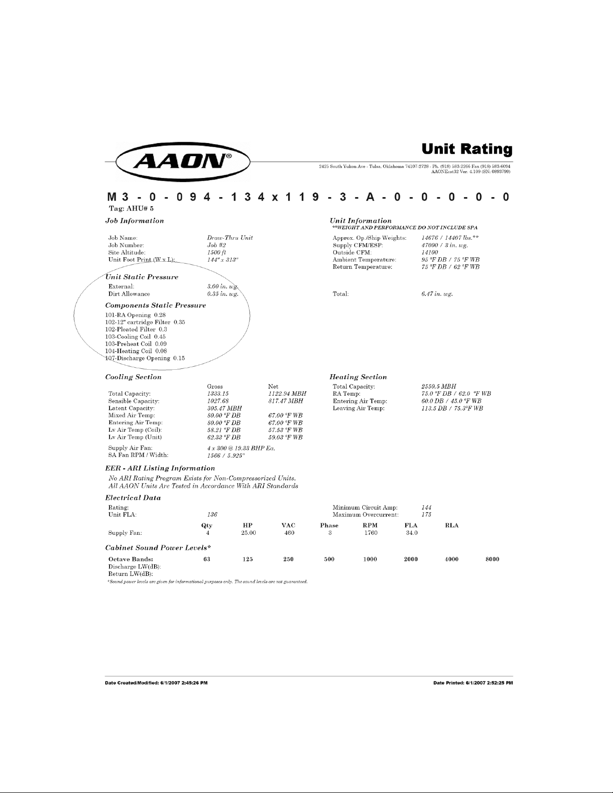
49
static pressure at the return air opening.
These values are listed on the Unit Rating
Sheet which can be obtained from the
AAON sales representative.
Figure 25 - Example Draw-Through AAONEcat32 Rating Sheet
Page 50

The following components should be added:
RA Opening 0.28”
12” Cartridge Filter 0.35”
Pleated Cartridge Filter 0.30”
Cooling Coil 0.45”
Preheat Coil 0.09”
Dirt Allowance 0.35”
These values should be added to the
absolute value of 1.5” to get a total of 3.32”
static pressure. Note that the heating coil
which is downstream of the drain pan and
the discharge opening static pressures are
not used in the calculation.
In this case the ‘X’ dimension of the drawthrough p-trap should be at least 4.32”,
which is the absolute value of the calculated
static pressure in the drain pan plus one
inch. The lower part of the p-trap should be
half that value, or 2.16”.
The total height of the p-trap would be 6.48”
measured from the bottom of the drain pan
connection to the top of the bottom bend, so
one diameter of the pipe needs to be added
to find the required clearance for the drain.
If the outside diameter of the pipe is 1.5” the
total clearance required would be 7.98”. If
the unit has a 6” base rail, accommodations
must be made for an additional 2” of drain
pipe to extend below the base rail.
Blow-Through Coils
Figure 26 - Blow-Through Drain Trap
The Y dimension of blow-through traps
should be at least equal to the value of the
positive pressure in the drain pan plus one
inch. This ensures that there will be enough
water stored in the trap to counter the static
pressure in the drain pan. To find the
pressure subtract any pressure drops
between the drain pan and the supply blower
from the blower discharge pressure. The
worst-case scenario for blow-thru coils is the
minimum pressure drop, so do not include
dirt allowance pressure drops for filters.
The bottom of the leaving pipe should be at
least one half inch lower than the bottom of
the drain pan connection. This ensures
proper drainage when the unit is not
running.
Note: It may be necessary to fill the trap
manually, or the trap can be filled
automatically by operating the unit until
enough condensate collects to fill the trap.
The trap will then be filled when the unit is
turned off.
50
Page 51

51
Blow-Through
Drain Pan Pressure
Trap Dimension
Positive Static
Y
(inches of water)
(inch)
0.5
1.5
1.0
2.0
1.5
2.5
2.0
3.0
2.5
3.5
3.0
4.0
3.5
4.5
4.0
5.0
4.5
5.5
5.0
6.0
Table 2 - Blow-Through Drain Trap
Dimensions
Page 52

Blow-Through P-Trap Example
Figure 27 - Blow-Through Drain Pan Connection Locations
In this case the supply external static
pressure is 3”. The only components
between the drain pan and the supply-air
ductwork are the discharge opening and the
heating coil. To find the static pressure in
the drain pan, subtract .08” and .15” from
52
the 3” supply air external static pressure.
This gives a positive pressure in the drain
pan of 2.77”. These values are listed on the
Unit Rating Sheet which can be obtained
from the AAON sales representative.
Page 53
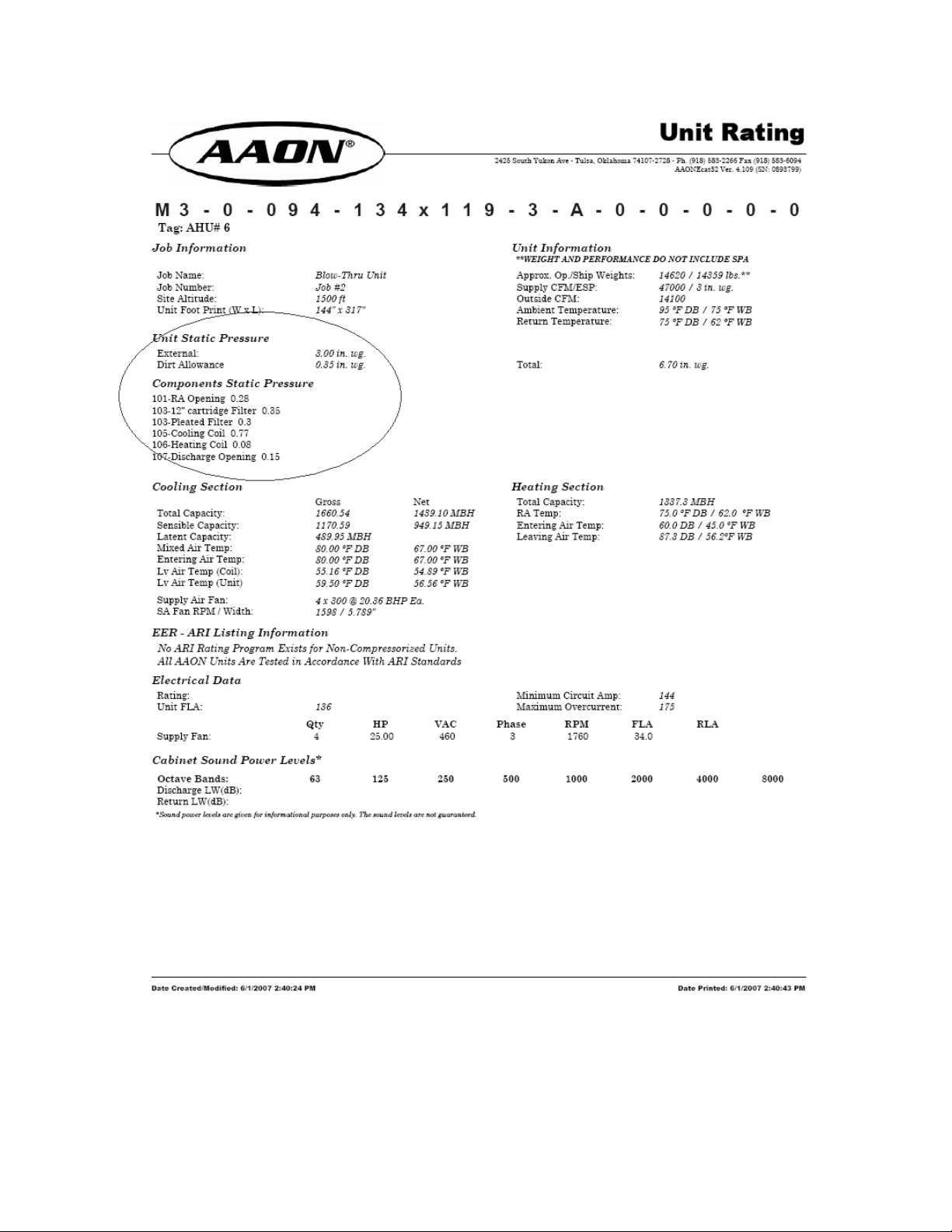
53
Figure 28 - Example Blow-Through AAONEcat32 Rating Sheet
Page 54
All drains must be trapped
individually before they are
connected to a common line.
All condensate drain connections
must be used. Drain pans are sloped
toward connections.
The ‘Y’ dimension on the blow-through ptrap should be at least 3.77”, or one inch
plus the calculated static pressure in the
drain pan. The total p-trap height will need
to be 3.77” plus at least .5” and then one
pipe diameter. If the outside diameter of the
p-trap pipe is 1.5” then the total height of the
trap would be 5.77”. A unit with the 6” base
rail would have sufficient height to properly
trap this example unit without additional
accommodations.
Base Drains
Base drains must be either capped or trapped
using the same methods as condensate
drains. If a base drain is to be trapped and
then piped, the trap must be manually filled
before unit operation and periodically
afterwards as the water evaporates.
External Control Panel
Note: The external control panel is heavy.
Installation is a multi-person job.
The optional external control panel may be
shipped loose from the factory. If it is
shipped loose, it is secured for shipping in
the supply fan module.
To install the external control panel use the
following procedure:
1. Remove the external control panel from
the shipping position in the supply fan
module.
2. Install the external control panel by
placing it on the preinstalled mounting
bracket on the exterior of the supply fan
module.
3. While one or two people hold the external
control panel in place on top of the
mounting bracket, another person should
secure it to the wall of the unit with selftapping #10 screws through the side angles
and top angles.
4. Push conduit and wiring from inside the
blower cabinet into the external control
panel and connect wiring according to the
provided wiring diagram.
5. Seal the hole in the foam wall by caulking
around the entire perimeter of the conduit on
both the inside and the outside of the unit.
Use an industrial grade silicone sealant or a
duct seal compound.
6. For outdoor units, the top and sides of the
external control panel assembly must be
sealed against the side of the unit. Apply
silicone or polyurethane caulking to the
seam along the top and both sides.
54
Page 55

55
Anytime a foam insulated part has a
hole or cutout in it, the exposed foam
must be sealed from the air stream.
All high voltage electrical connections
should be checked for tightness prior
to unit startup. Loose connections
can cause overheating and
component failure.
The foam insulation releases
dangerous fumes when it is burnt. Do
not cut a foam part with a cutting
torch or plasma cutter. Do not weld to
a foam filled part.
Figure 29 - External Control Panel
Electrical
All external wiring must comply with the
National Electric Code (NEC) and any
additional local codes. It is the responsibility
of the installer to conform to all necessary
codes. All internal wiring complies with UL
1995
Note: All voltages should be within 10% of
unit and component nameplate voltages.
Check the unit data plate to make sure it
agrees with the power supply. For units
that contain factory wiring, connect power
supply to the unit according to the provided
wiring diagram.
All wiring should be done in conduit on the
exterior of the unit. Control wiring should
not be run in the same conduit as power
wiring. Protect the branch circuit in
accordance with code requirements.
The unit must be electrically grounded in
accordance with the National Electric Code,
ANSI / NFPA No. 70. In Canada use current
C.S.A. Standard C22.1, Canadian Electric
Code Part 1.
For field wired units, refer to the motor
connection diagram on the inside of the
motor terminal box for wiring instructions.
Check the electrical characteristics of the
motor to make sure they correspond to the
supply voltage and the conductor size used.
Foam Insulated Panel Cutting
Note: The location for field cut electrical
entry is marked on the unit. Field cut
openings must be a minimum of 6 inches
away from all components and wiring to
prevent damage due to drilling or cutting.
To pass wires through the wall or roof of the
unit, a hole should be cut and conduit passed
Page 56

Care should be taken to ensure that
the dampers do not fail to a position
where all are closed while the fan is
still running. This can result in
damage to the unit.
through it. Use the following procedure to
cut a round hole in a foam panel.
1. Locate the placement of the hole. Be sure
that the conduit will not interfere with the
operation of any component or prevent
access of any door or removable panel.
2. Drill a pilot hole all the way through the
foam wall or roof.
3. Using a hole saw cut the hole through the
metal on both sides of the foam part.
4. With a knife cut the foam out of the hole.
5. After the conduit or pipe is installed in the
hole caulk the entire perimeter of the hole on
both sides with an industrial grade silicone
sealant or a duct seal compound.
If a larger cut-out is needed for additional
duct connections not provided by the
factory, or for any other reason, it is very
important that the foam be completely
sealed. Insulation covers should be
fabricated from sheet metal to cover the
foam at the cut. The edges and corners that
are not covered should then be sealed using
silicone caulking or a duct seal compound.
If a reciprocating saw is used to make the
cut-out take care that the metal skins of the
foam part do not separate from the foam,
this would result in reduced structural
integrity of the part.
Dampers and Actuators
56
AAON damper blades are connected with
interlocking gears. A coupling is attached to
one of the gears for connection to the
actuator.
Factory provided actuators have a spring
return. The recommended configuration is
that the return air actuator should return to
an open position and the exhaust and outside
air should return to a closed position.
It is recommended that field provided
actuators also be spring return with the same
configuration listed above.
The factory provided actuators use a 24V
power supply and are either on/off or
modulating using a 2-10 VDC signal.
Figure 30 - Dampers
Page 57
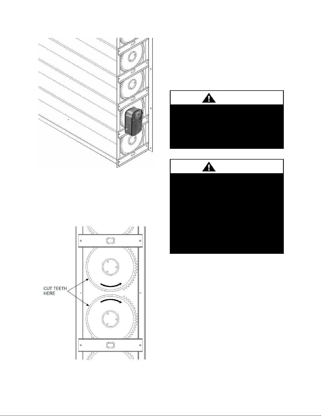
57
PVC (Polyvinyl Chloride) and CPVC
(Chlorinated Polyvinyl Chloride) are
vulnerable to attack by certain
chemicals. Polyolester (POE) oils
used with R-410A and other
refrigerants, even in trace amounts,
in a PVC or CPVC piping system will
result in stress cracking of the piping
and fittings and complete piping
system failure.
All piping design and installation
should be performed by qualified
professionals. All applicable codes
and industry standards should be
adhered to.
Figure 31 - Dampers and Actuator
Note: If one damper bank is to be
independently controlled by two actuators,
the two gears that join the separate portions
will need to be cut so that they do not
engage each other.
Figure 32 - Independently Controlled
Dampers
Duct System
Remove duct shipping covers immediately
prior to duct connection. A 1 inch tall duct
flange is provided around each duct
opening.
Piping
The coil connections are copper MPT. Use
dielectric unions as necessary to prevent
galvanic-corrosion.
Always use a backup pipe wrench to prevent
excess stress and damage to coil
connections. The connecting piping should
never be supported by the coil, it should be
independently supported. Swing joints or
flexible fittings should be used to absorb
expansion and contraction due to
temperature changes.
An access cover is provided for the chilled
water, hot water, and steam coil vent and
Page 58

Improper installation, adjustment,
alteration, service or maintenance
can cause property damage,
personal injury or loss of life. Startup
and service must be done by a
Factory Trained Service Technician.
A copy of this IOM should be kept
with the unit.
Equipment operation during
construction will void all
manufacturer’s warranties.
drains. Remove the two bolts by each coil
connection. When replacing the cover, take
care not to over-tighten the bolts as this
could cause the rivet-nut to come loose.
Vents and drains are sealed with half inch
plugs.
All coils should be piped in a counter-flow
arrangement. The water entering connection
should be on the air leaving side of the coil.
Figure 33 - Hydronic Coil Connections
58
Operation
Before starting up the equipment, building
construction should be complete. Startup
personnel should:
• Have a working knowledge of general
HVAC and mechanical commissioning
procedures and practices.
• Be familiar with unit functions, features,
optional unit accessories, and all control
sequences.
• Have appropriate literature on hand for
consultation.
Startup Checklist
• Check all electrical connections for
tightness.
• Inspect all sections. Remove any shipping
restraints and check for loose debris.
• Check fan set screws for tightness, turn
fan to assure free rotation.
• Ensure electrical supply matches unit
nameplate.
• Ensure condensate lines are connected,
glued, and sloped towards building drain.
• Manually fill any trapped drains.
(Condensate drains will fill automatically)
Page 59

59
Improper startup procedures could
damage unit and possibly void
manufacturer’s warranties.
Startup check list must be completed
before turning unit power on.
• Check for compliance of all codes and
special provisions.
• Attach all access panels, close all doors.
• Ensure that ductwork dampers are open.
Procedures
Install any gauges, voltmeter, and ammeter
before startup. If any excess sound or
vibration occurs during startup, note and
determine the cause, and shut off unit
immediately to correct.
1. Turn the unit power on.
2. One at a time turn on all blowers, check
for correct rotation. Units with factory
wiring have been tested. If motor rotation is
not correct, switch position of two legs of
power at the power entry. Rotation may
need to be corrected for each motor for field
wired units. Plenum fans should rotate
clockwise as viewed from the air leaving
side of the motor.
3. When rotation directions are correct, take
blower amp readings and check to make
sure they are within the safety factor of the
motor.
Figure 34 - Blower Rotation
4. With the blowers off, check the operation
of all dampers. Ensure that the dampers are
operating such that airflow through the unit
will not be shut off while the fan is
operating. This could cause severe damage
to the unit.
5. Check the operation of all water valves.
Simulate calls for cooling and heating,
check for the proper response of the valves.
Check the operation of any other optional
equipment per the manufacturer’s
specifications.
Commissioning
The commissioning of an air conditioning
system is the process of achieving,
verifying, and documenting the performance
of that system to meet the operational needs
of the building. Adjustments made during
the commissioning phase may include air or
water balancing, or configuration of controls
and operational sequences.
Air Balancing
High performance systems commonly have
complex air distribution and fan systems.
Unqualified personnel should not attempt to
adjust fan operation or air circulation, as all
systems have unique operating
characteristics. Professional air balance
Page 60

specialists should be employed to establish
actual operating conditions and to configure
the air delivery system for optimal
performance.
Water Balancing
A hydronic specialist with a complete
working knowledge of water systems,
controls, and operation must be employed to
properly balance the entire system.
Unqualified personnel should not attempt to
manipulate temperatures, pressures, or flow
rates, as all systems have unique operating
characteristics and improper balancing can
result in undesirable noises and operation.
Controls
M3 Series air handlers can be shipped from
the factory with no controls and no wiring,
wired to terminal blocks, or with a factory
installed WattMaster VCM-X controller. If
the unit includes a VCM-X controller, the
technical guide will be included with the
literature package.
Operate unit according to control
manufacturer’s instructions. Contact sales
representative or controls contractor for
information on non-factory controls.
Maintenance
Routine Maintenance
Routine maintenance is required to keep the
unit running efficiently and minimize down
time. The following maintenance schedule
should be used.
One week after start-up:
• Check filters for cleanliness. Replace if
necessary.
• Check cycling of fans and valves. Correct
unusual cycling.
• Check for correct damper operation.
• Check blower set screws. Tighten if
necessary.
Monthly:
• Check filters for cleanliness. Replace if
necessary.
• Check drain pans to ensure proper drainage
and clean as necessary.
• Inspect all coils. Clean if dirty or
obstructed in any way.
Seasonal:
• Check operation of heating and cooling
sequences.
• Check for correct damper operation.
• Check fans for wear. Clean if necessary.
Refer to motor manufacturer IOM for relubrication schedule.
• Winterize coils if necessary.
• Inspect and if necessary clean unit interior.
Yearly:
• Clean coils, drain pan and drain line.
• Check electrical connections for tightness.
• Check piping and valves for correct
operation.
Blower Assembly
The M3 Series air handling unit uses only
direct drive fans. The only bearings that will
need to be lubricated are the ones contained
in the motor. Refer to the motor
manufacturer maintenance manual for the
correct re-lubrication schedule and lubricant
information.
It is important that fans be kept clean to
maintain efficiency and reduce stress on the
unit. To clean the fans first make sure the
power to the unit is turned off. Secure the
fan so it cannot free-wheel. Clean dust and
debris on the fan. Check set screws for
tightness. Rotate the fan by hand and check
for noise and roughness. The fan should
rotate smoothly.
Coils/Drain Pans
Coils must be kept clean to maintain peak
unit efficiency and capacity. Clean filters
60
Page 61

61
When steam cleaning coils, be sure
area on both sides of coil is clear of
excess personnel.
Take care that the coil is not dropped
or knocked over. This could damage
the coil fins, or cause a leak in the
coil.
will help prevent dirty coils; however, coils
should still be cleaned at least annually by
an HVAC professional.
The coils should be cleaned using steam,
low-pressure water, low-pressure air, or a
non-corrosive coil cleaner.
Take care not to damage fins while cleaning.
High pressure water can damage fins.
Condensate drain pans should be inspected
often and cleaned at least annually to
maintain proper drainage and prevent the
spread of disease. Cooling coils are raised
off the drain pan to facilitate cleaning.
The drain and p-traps should also be
checked to prevent clogging. A clogged
drain will result in water backing up in the
drain pan and potentially damaging the unit
and the building.
Winterizing Coils
In some cases it may be necessary to
winterize water coils to prevent them from
freezing.
First completely drain the coils. There is a
drain located below the ‘water in’
connection and a vent connection located
above the ‘water out’ connection. Auxiliary
drain piping can also be added to exterior
water piping if yearly winterizing is
necessary.
After the coil is drained, fill with an
antifreeze solution using a circulating pump.
Then thoroughly drain.
Removing Coils
Coils on the M3 units can be removed from
either side of the unit. The coils are
independently supported so they can be
removed independently from either side of
the unit.
To remove a coil, first disconnect the water
piping from the coil. Remove the coil access
panel on the side from which the coil is to be
removed. Remove the screws connecting
coil end panel to the coil. Slide the coil
straight out onto a support that is at the same
level as the coil.
To replace the coil, the above procedure
should be reversed. The coil should first be
placed on a support that is at the same level
as the coil position in the unit. The coil
should then be slid straight into the unit.
The upper coil location has angles on both
the front and back side of the coil; the lower
coil has an angle on the downstream side of
the coil and guides on the upstream side. Be
sure that the coil is all the way up against the
front (downstream) side of the coil, this
should center the coil in the opening.
Push the coil all the way in so that the
return-bend side of the coil is between 1/8”
and 1/4” from the inside wall of the unit. For
cooling coils, be sure that the vertical
headers are entirely over the drain pan.
Screw the coil end panel to the coil using
self-tapping sheet metal screws.
Page 62

Shut off power to unit and wait for
fans to stop turning before removing
an access panel. To make sure the
unit is not pressurized, open door
opposite the access panel. Serious
injury can result from removing a
panel under positive pressure.
To remove an access panel, remove bolts
from the perimeter. When replacing a panel,
make sure that the neoprene gasket on the
panel is not damaged. Do not over-tighten
the bolts as this could cause the rivet-nuts to
come loose.
Figure 35 - Coil Removal
Doors/Panels
Removable access panels are provided
directly across from most access doors. If
regular access is required from the panel
side of the unit, the doors and panels can be
swapped or additional doors can be ordered
from the factory. Contact sales
representative to order additional parts.
Note: For safety, inside-opening doors are
used in positive pressure sections and
outside-opening doors are used in negative
pressure sections. The opening direction of
doors cannot be changed.
62
Figure 36 - Access Door/Panel Removal
Outside Opening Door and Panel
To switch the door and access panel
locations remove panel and remove door by
removing the screws connecting the hinge to
the unit. For inside opening doors, the gap
covers around the door opening should also
be removed.
Page 63

63
Figure 37 - Access Door
Install the door on the opposite side of the
unit by attaching the hinge to the unit. Be
sure that the door is centered in the opening.
Rubber gasket needs to be applied on the
door jamb of the new door side. The door
latch parts will need to be removed and
replaced on the new door side.
Filters
Pleated filters install from upstream side of
filter rack. Filters are installed in columns.
For each column open snap-fasteners and
remove first filter. Slide the rest of the filters
to the opening and then remove.
Bag and cartridge filters are installed with a
type 8 holding frame. Use the provided clips
to attach new filters. Be sure to remove prefilter clips from cartridge filters before
discarding. Pre-filter clips will need to be
attached to replacement cartridge filters.
Page 64

Unit Size
Filter Size
Qty Wide
Qty High
Total Qty
Face Area
032
20” x 16”
4 4 16
35.56 ft
2
039
20” x 16”
4 5 20
44.44 ft2
045
20” x 16”
4 5 20
44.44 ft2
054
20” x 16”
5 5 25
55.56 ft2
060
20” x 16”
5 6 30
66.67 ft2
067
20” x 16”
6 6 36
80.00 ft2
074
25” x 16”
5 6 30
83.33 ft2
083
25” x 20”
5 5 25
86.81 ft2
094
25” x 16”
5 7 35
97.22 ft2
Unit Size
Filter Size
Qty Wide
Qty High
Total Qty
Face Area
032
20” x 16”
5 4 20
44.44 ft
2
039
20” x 16”
5 5 25
55.56 ft
2
045
24” x 20”
5 4 20
66.67 ft
2
054
20” x 16”
6 5 30
66.67 ft
2
060
20” x 16”
6 6 36
80.00 ft
2
067
20” x 16”
7 6 42
93.33 ft
2
074
25” x 16”
6 6 36
100.00 ft
2
083
25” x 20”
6 5 30
104.17 ft
2
094
25” x 16”
6 7 42
116.67 ft
2
Unit Size
Primary
Filter Size
Quantity
Secondary
Filter Size
Quantity
Face Area
032
20” x 20”
12
12” x 24”
2
37.33 ft2
039
20” x 24”
12
12” x 24”
3
46.00 ft2
045
20” x 20”
16
12” x 24”
3
50.44 ft2
054
20” x 20”
16
20” x 24”
4
57.78 ft2
060
20” x 24”
20
NA
NA
66.67 ft2
067
20” x 24”
20
12” x 24”
5
76.67 ft2
074
20” x 24”
20
12” x 24”
8
82.67 ft2
083
20” x 24”
25
12” x 24”
4
91.33 ft2
094
20” x 24”
25
12” x 24”
9
101.33 ft2
Table 3 - Flat Pleated Filters
Table 4 - Angled Pleated Filters
Table 5 - Cartridge/Bag Filters
64
Page 65
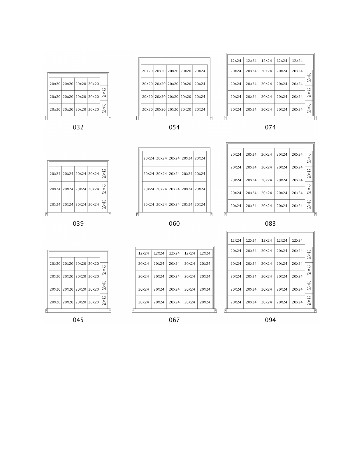
65
Figure 38 - Cartridge/Bag Filter Layout Viewed from Upstream Side.
Filters Face Load Into Type 8 Holding Frame.
Page 66

Job Name:_______________________________________________
Date:______________
Address:______________________________________________________________________
______________________________________________________________________________
Model Number:_________________________________________________________________
Serial Number:_____________________________________________
Tag:_______________
Startup Contractor:______________________________________________________________
Address:______________________________________________________________________
_______________________________________________________
Phone:______________
Installing contractor should verify the following items.
1. Is there any visible shipping damage?
Yes No
2. Is the unit level?
Yes No
3. Are the unit clearances adequate for service and operation?
Yes No
4. Do all access doors open freely and are the handles operational?
Yes No
5. Have all shipping braces been removed?
Yes No
6. Have all electrical connections been tested for tightness?
Yes No
7. Does the electrical service correspond to the unit nameplate?
Yes No
8. On 208/230V units, has transformer tap been checked?
Yes No
9. Has overcurrent protection been installed to match the unit nameplate
requirement?
Yes No
10. Have all set screws on the fans been tightened?
Yes No
11. Do all fans rotate freely?
Yes No
12. Does the field water piping to the unit appear to be correct per design
parameters?
Yes No
13. Is all copper tubing isolated so that it does not rub?
Yes No
14. Have the damper assemblies been inspected?
Yes No
15. Are air filters installed with proper orientation?
Yes No
16. Have condensate drain and p-trap been connected?
Yes No
Ambient Dry Bulb Temperature ________°F
Ambient Wet Bulb Temperature ________°F
Pre Startup Checklist
M3 Series Startup Form
Ambient Temperature
66
Page 67

67
Alignment
Check Rotation
Nameplate Amps________
Number
hp
L1
L2
L3
1
2
3
4
Band Size_____________________
VAV Controls_________________
VFD Frequency________________
Springs Operating Correctly
Wheels Spin Freely
Check Rotation
FLA ________
Number
hp
L1
L2
L3
1
2
Alignment
Check Rotation
Nameplate Amps________
Number
hp
L1
L2
L3
1
2
Band Size_____________________
VFD Frequency________________
Springs Operating Correctly
Alignment
Check Rotation
Nameplate Amps________
Number
hp
L1
L2
L3
1
2
Band Size_____________________
VFD Frequency________________
Springs Operating Correctly
Supply Fan Assembly
Energy Recovery Wheel Assembly
Power Exhaust Fan Assembly
Power Return Fan Assembly
Page 68
OA Operation Check
Damper Wiring Check
Gears Check
RA Operation Check
Damper Wiring Check
Gears Check
EA Operation Check
Damper Wiring Check
Gears Check
Damper Actuator Type:__________________________________________________________
Economizer Changeover Type and Operation:_______________________________________
Stages__________
Limit Lockout
Aux. Limit Lockout
Door Interlock
Stage
Amps
Stage
Amps 1 7 2 8 3 9 4
10 5 11 6 12
Outside Air/Economizer Dampers
Electric Heating
68
Page 69

69
Entry Date
Action Taken
Name/Tel.
Maintenance Log
This log must be kept with the unit. It is the responsibility of the owner and/or
maintenance/service contractor to document any service, repair, or adjustments. AAON Service
and Warranty Departments are available to advise and provide phone help for proper operation
and replacement parts. The responsibility for proper startup, maintenance, and servicing of the
equipment falls to the owner and qualified licensed technician.
Page 70

Literature Change History
June 2010
Update of the IOM adding PVC and CPVC piping Caution and revising the Module Assembly
section.
April 2012
Update of the IOM changing the 2” pleated 30% efficient filter from MERV 7 to MERV 8,
correcting the Unit Lifting Drawing to show a 60 degree minimum strap angle, adding the
electronic startup form, adding the index of tables and figures, and updating the table of contents.
March 2014
Updated factory trained service technician text and feature string nomenclature.
70
Page 71

Page 72
AAON
2425 South Yukon Ave.
Tulsa, OK 74107-2728
Phone: 918-583-2266
Fax: 918-583-6094
www.aaon.com
M3 Series
Installation, Operation &
Maintenance
R57350 · Rev. D · 140307
It is the intent of AAON to provide accurate and current product information. However, in the
interest of product improvement, AAON reserves the right to change pricing, specifications
and/or design of its product without notice, obligation or liability.
Copyright © AAON, all rights reserved throughout the world.
AAON® and AAONAIRE® are registered trademarks of AAON, Inc., Tulsa, OK.
 Loading...