

Page 1
G
M2 Series
Modular Indoor Air Handling Units,
Modular Outdoor Air Handling Units,
Self Contained Units & Packaged Rooftop Units
Installation, Operation
& Maintenance
FIRE OR EXPLOSION HAZARD
Failure to follow safety warnings
exactly could result in serious injury,
death or property damage.
Be sure to read and understand the
installation, operation and service
instructions in this manual.
Improper installation, adjustment,
alteration, service or maintenance
can cause serious injury, death or
property damage.
A copy of this IOM should be kept
with the unit.
Do not store gasoline or other
flammable vapors and liquids in the
vicinity of this or any other appliance.
WHAT TO DO IF YOU SMELL GAS
Do not try to light any appliance.
Do not touch any electrical switch;
Leave the building immediately.
Immediately call you gas supplier
If you cannot reach your gas
Installation and service must be
performed by a qualified installer,
service agency or the gas supplier.
do not use any phone in your
building.
from a phone remote from the
building. Follow the gas supplier’s
instructions.
supplier call the fire department.
WARNIN
Page 2

Page 3

Table of Contents
Safety .............................................................................................................................................. 7
Model Number Nomenclature ...................................................................................................... 13
M2 Base Model Description ......................................................................................................... 14
Fan Module Description ............................................................................................................... 15
Filter Module Description ............................................................................................................. 16
Mixing Box Module Description .................................................................................................. 17
Heat Module Description .............................................................................................................. 18
Blank Module Description ............................................................................................................ 19
Coil Module Description............................................................................................................... 20
Control Panel Module Description ............................................................................................... 21
Energy Recovery Module Description .......................................................................................... 22
Condenser Module Description .................................................................................................... 23
Typical Configurations ................................................................................................................. 24
Unit Orientation ............................................................................................................................ 25
General Information ...................................................................................................................... 26
Codes and Ordinances ............................................................................................................... 27
Receiving Unit ........................................................................................................................... 27
Storage ....................................................................................................................................... 28
Packaged Direct Expansion (DX) Units .................................................................................... 28
Gas or Electric Heating ............................................................................................................. 29
Wiring Diagrams ....................................................................................................................... 29
Condensate Drain Pan ............................................................................................................... 29
Installation..................................................................................................................................... 30
Locating Units ........................................................................................................................... 30
Lifting the Unit .......................................................................................................................... 31
Indoor Floor Mounted Units ..................................................................................................... 34
Indoor Suspended Units ............................................................................................................ 34
Module Assembly ..................................................................................................................... 35
Refrigerant Piping ..................................................................................................................... 39
Determining Refrigerant Line Size ........................................................................................... 40
Water-Cooled Condenser .......................................................................................................... 44
Open Loop Applications ........................................................................................................ 44
Freezing Water in the Heat Exchanger .................................................................................. 45
Water Piping .......................................................................................................................... 46
Water-Cooled Condenser Safeties ......................................................................................... 49
Electrical .................................................................................................................................... 49
Cutting Electrical Openings ................................................................................................... 50
Thermostat Control Wiring .................................................................................................... 51
Condensate Drain Piping ........................................................................................................... 52
Blower Wheels .......................................................................................................................... 53
Air Adjustment ...................................................................................................................... 54
Waterside Economizer .............................................................................................................. 55
Hot Water and Steam Coils ....................................................................................................... 56
Chilled Water Coils ................................................................................................................... 56
Electric Heating ......................................................................................................................... 56
3
Page 4

Gas Fired Duct Furnace ............................................................................................................. 57
Duct Furnace Component Identification ................................................................................... 59
Furnace Maintenance ................................................................................................................ 66
Troubleshooting ........................................................................................................................ 67
Startup ........................................................................................................................................... 68
Filters ......................................................................................................................................... 68
Check Out .................................................................................................................................. 68
Commissioning .......................................................................................................................... 69
Operation ................................................................................................................................... 70
Adjusting Refrigerant Charge ................................................................................................... 70
Maintenance .................................................................................................................................. 74
Fan Assembly ............................................................................................................................ 74
Bearings ..................................................................................................................................... 74
Belts ........................................................................................................................................... 75
Indoor Coils ............................................................................................................................... 76
Refrigeration Cycle ................................................................................................................... 76
E-Coated Coil Cleaning ............................................................................................................ 76
Recommended Coil Cleaner .................................................................................................. 77
Recommended Chloride Remover ......................................................................................... 77
Energy Recovery Wheel ............................................................................................................ 77
Electric Heating ......................................................................................................................... 79
Steam or Hot Water Heating ..................................................................................................... 79
Cleaning .................................................................................................................................... 79
Chilled Water ............................................................................................................................ 79
Lubrication ................................................................................................................................ 79
Replacement Parts ..................................................................................................................... 80
AAON-Longview Customer Service Department .................................................................... 80
Filter Replacement .................................................................................................................... 80
Appendix A - Heat Exchanger Corrosion Resistance ................................................................... 82
Refrigerant Piping Diagrams ........................................................................................................ 84
M2 Series Startup Form ................................................................................................................ 91
Maintenance Log .......................................................................................................................... 97
R40681 · Rev. B · 120509
(ACP 30752)
4
Page 5

Index of Tables and Figures
Tables:
Table 1 - Minimum Clearances ..................................................................................................... 31
Table 2 - Glycol Freezing Points .................................................................................................. 46
Table 3 - Freezing Points .............................................................................................................. 48
Table 4 - Coaxial Heat Exchanger Pressure Drops (WCC- & WHP-) ......................................... 48
Table 5 - Brazed Plate Heat Exchanger Pressure Drops (WCC- & WHP-) ................................. 49
Table 6 - Control Wiring ............................................................................................................... 51
Table 7 - Drain Trap Dimensions ................................................................................................. 52
Table 8 - Blow-Through Drain Trap Dimensions......................................................................... 53
Table 9 - Gas Heater Troubleshooting .......................................................................................... 64
Table 10 - Gas Heater Troubleshooting Continued ...................................................................... 65
Table 11 - Problems, Causes and Solutions .................................................................................. 67
Table 12 - Acceptable Air-Cooled Refrigeration Circuit Values ................................................. 71
Table 13 - Acceptable Water-Cooled Refrigeration Circuit Values ............................................. 71
Table 14 - R-410A Refrigerant Temperature-Pressure Chart ....................................................... 73
Table 15 - Bearing Setscrew Torque Recommendations .............................................................. 75
Table 16 - Fan Bearing Lubrication Schedule .............................................................................. 79
Table 17 - M2-005 and M2-008 Filters ........................................................................................ 80
Table 18 - M2-011 and M2-014 Filters ........................................................................................ 80
Table 19 - M2-018 and M2-022 Filters ........................................................................................ 81
Table 20 - M2-026 Filters ............................................................................................................. 81
Table 21 - M2-032 and M2-036 Filters ........................................................................................ 81
5
Page 6

Figures:
Figure 1 - Typical Configurations ................................................................................................. 24
Figure 2 - Unit Orientation ........................................................................................................... 25
Figure 3 - Lockable Handle .......................................................................................................... 28
Figure 4 - Service Access Clearance ............................................................................................ 31
Figure 5 - M2 Series Unit Four Point Lifting ............................................................................... 32
Figure 6 - M2 Series Unit Eight Point Lifting .............................................................................. 33
Figure 7 - Unit Suspension ........................................................................................................... 34
Figure 8 - Module Assembly Schematic ....................................................................................... 36
Figure 9 - Bulb Gasket .................................................................................................................. 37
Figure 10 - Applying Bulb Gasket ................................................................................................ 37
Figure 11 - Gasket Application ..................................................................................................... 37
Figure 12 - Bolted Base Rail ......................................................................................................... 37
Figure 13 - Bar Clamp .................................................................................................................. 38
Figure 14 - Self-Tapping Screw .................................................................................................... 38
Figure 15 - Strap Types................................................................................................................. 38
Figure 16 - Strap Locations........................................................................................................... 38
Figure 17 - Strap Installation ........................................................................................................ 39
Figure 18 - Draw-Through Drain Trap ......................................................................................... 52
Figure 19 - Blow-Through Drain Trap ......................................................................................... 53
Figure 20 - Supply Fan Banding ................................................................................................... 55
Figure 21 - Sediment Trap ............................................................................................................ 58
Figure 22 - Horizontal Configuration ........................................................................................... 59
Figure 23 - Vertical Configuration ............................................................................................... 59
Figure 24 - Gas Valve ................................................................................................................... 59
Figure 25 - 1.2” w.c. Manifold ..................................................................................................... 61
Figure 26 - 3.5” w.c. Manifold ..................................................................................................... 61
Figure 27 - Flame Sensor Current Check ..................................................................................... 62
Figure 28 - Angular Misalignment ............................................................................................... 75
Figure 29 - Parallel Misalignment ................................................................................................ 75
Figure 30 - Belt Deflection ........................................................................................................... 75
Figure 31 - Energy Recovery Wheel ............................................................................................ 78
Figure 32 - Standard Split System Piping ..................................................................................... 84
Figure 33 - Modulating Hot Gas Reheat with Hot Gas Bypass Split System Piping ................... 85
Figure 34 - Hot Gas Bypass Split System Piping ......................................................................... 86
Figure 35 - Modulating Hot Gas Reheat Split System Piping ...................................................... 87
Figure 36 - Heat Pump Split System Piping ................................................................................. 88
Figure 37 - Heat Pump with Factory Installed Modulating Hot Gas Reheat Split System Piping 89
Figure 38 - Heat Pump with Field Installed Modulating Hot Gas Reheat Split System Piping ... 90
6
Page 7
Safety
NOTE - Notes are intended to clarify the unit installation, operation and maintenance.
CAUTION - Caution statements are given to prevent actions that may result in
equipment damage, property damage, or personal injury.
WARNING - Warning statements are given to prevent actions that could result in
equipment damage, property damage, personal injury or death.
DANGER - Danger statements are given to prevent actions that will result in equipment
damage, property damage, severe personal injury or death.
Attention should be paid to the following statements:
ELECTRIC SHOCK, FIRE OR
EXPLOSION HAZARD
Failure to follow safety warnings
exactly could result in dangerous
operation, serious injury, death or
property damage.
Improper servicing could result in
dangerous operation, serious injury,
death, or property damage.
Before servicing, disconnect all
When servicing controls, label all
Verify proper operation after
electrical power to the furnace.
More than one disconnect may be
provided.
wires prior to disconnecting.
Reconnect wires correctly.
servicing. Secure all doors with
key-lock or nut and bolt.
WARNING
Improper installation, adjustment,
alteration, service or maintenance
can cause property damage,
personal injury or loss of life.
Installation and service must be
performed by a trained, qualified
installer. A copy of this IOM should
be kept with the unit.
WHAT TO DO IF YOU SMELL GAS
Do not try to turn on unit.
Shut off main gas supply.
Do not touch any electric switch.
Do not use any phone in the
Never test for gas leaks with an
Use a gas detection soap solution
QUALIFIED INSTALLER
building.
open flame.
and check all gas connections
and shut off valves.
7
Page 8
G
Electric shock hazard. Before
servicing, shut off all electrical power
to the unit, including remote
disconnects, to avoid shock hazard
or injury from rotating parts. Follow
proper Lockout-Tagout procedures.
FIRE, EXPLOSION OR CARBON
MONOXIDE POISONING HAZARD
Failure to replace proper controls
could result in fire, explosion or
carbon monoxide poisoning. Failure
to follow safety warnings exactly
could result in serious injury, death or
property damage. Do not store or use
gasoline or other flammable vapors
and liquids in the vicinity of this
appliance.
During installation, testing, servicing,
and troubleshooting of the equipment
it may be necessary to work with live
electrical components. Only a
qualified licensed electrician or
individual properly trained in handling
live electrical components shall
perform these tasks.
Standard NFPA-70E, an OSHA
regulation requiring an Arc Flash
Boundary to be field established and
marked for identification of where
appropriate Personal Protective
Equipment (PPE) be worn, should be
followed.
WARNING
ROTATING COMPONENTS
Unit contains fans with moving parts
that can cause serious injury. Do not
open door containing fans until the
power to the unit has been
disconnected and fan wheel has
stopped rotating.
GROUNDING REQUIRED
All field installed wiring must be
completed by qualified personnel.
Field installed wiring must comply
with NEC/CEC, local and state
electrical code requirements. Failure
to follow code requirements could
result in serious injury or death.
Provide proper unit ground in
accordance with these code
requirements.
VARIABLE FREQUENCY DRIVES
Do not leave VFDs unattended in
hand mode or manual bypass.
Damage to personnel or equipment
can occur if left unattended. When in
hand mode or manual bypass mode
VFDs will not respond to controls or
alarms.
WARNIN
8
Page 9
CAUTIO
CAUTIO
Electric motor over-current protection
and overload protection may be a
function of the Variable Frequency
Drive to which the motors are wired.
Never defeat the VFD motor overload
feature. The overload ampere setting
must not exceed 115% of the electric
motors FLA rating as shown on the
motor nameplate.
N
To prevent injury or death lifting
equipment capacity shall exceed unit
weight by an adequate safety factor.
Always test-lift unit not more than 24
inches high to verify proper center of
gravity lift point to avoid unit damage,
injury or death.
WARNING
UNIT HANDLING
Rotation must be checked on all
MOTORS AND COMPRESSORS of
3 phase units at startup by a qualified
service technician. Scroll
compressors are directional and can
be damaged if rotated in the wrong
direction. Compressor rotation must
be checked using suction and
discharge gauges. Fan motor rotation
should be checked for proper
operation. Alterations should only be
made at the unit power connection
Failure to properly drain and vent
coils when not in use during freezing
temperature may result in coil and
equipment damage.
N
Do not use oxygen, acetylene or air
in place of refrigerant and dry
nitrogen for leak testing. A violent
explosion may result causing injury or
death.
Prior to connection of condensing
water supply, verify water pressure is
less than maximum pressure shown
on unit nameplate. To prevent injury
or death due to instantaneous
release of high pressure water, relief
valves should be field supplied on
system water piping.
WATER PRESSURE
Always use a pressure regulator,
valves and gauges to control
incoming pressures when pressure
testing a system. Excessive pressure
may cause line ruptures, equipment
damage or an explosion which may
result in injury or death.
9
Page 10
CAUTIO
CAUTIO
G
To prevent damage to the unit, do not
use acidic chemical coil cleaners. Do
not use alkaline chemical coil
cleaners with a pH value greater than
8.5, after mixing, without first using
an aluminum corrosion inhibitor in the
cleaning solution.
N
Some chemical coil cleaning
compounds are caustic or toxic. Use
these substances only in accordance
with the manufacturer’s usage
instructions. Failure to follow
instructions may result in equipment
damage, injury or death.
WARNING
Door compartments containing
hazardous voltage or rotating parts
are equipped with door latches to
allow locks. Door latch are shipped
with nut and bolts requiring tooled
access. If you do not replace the
shipping hardware with a pad lock
always re-install the nut & bolt after
closing the door.
Do not clean DX refrigerant coils with
hot water or steam. The use of hot
water or steam on refrigerant coils
will cause high pressure inside the
coil tubing and damage to the coil.
Cleaning the cooling tower or the
condenser water loop with harsh
chemicals, such as hydrochloric acid
(muriatic acid) or chlorine, can
damage the water-cooled condenser.
Care should be taken to avoid
allowing chemicals to enter the
water-cooled condenser. See
Appendix A - Heat Exchanger
Corrosion Resistance for more
information.
N
Failure of the condenser as a result
of chemical corrosion is excluded
from coverage under AAON Inc.
warranties and the heat exchanger
manufacturer’s warranties.
WARNIN
OPEN LOOP APPLICATIONS
Failure of the condenser due to
freezing will allow water to enter the
refrigerant circuit and will cause
extensive damage to the refrigerant
circuit components. Any damage to
the equipment as a result of water
freezing in the condenser is excluded
from coverage under AAON
warranties and the heat exchanger
manufacturer warranties.
WATER FREEZING
10
Page 11
Disconnect all power, close all
isolation valves and allow equipment
to cool before servicing equipment to
prevent serious injury. Equipment
may have multiple power supplies.
Electric resistance heating elements
and hot water or steam heating coils
may have automatic starts. Hot water
will circulate even after power is off.
HOT PARTS
PVC (Polyvinyl Chloride) and CPVC
(Chlorinated Polyvinyl Chloride) are
vulnerable to attack by certain
chemicals. Polyolester (POE) oils
used with R-410A and other
refrigerants, even in trace amounts,
in a PVC or CPVC piping system will
result in stress cracking of the piping
and fittings and complete piping
system failure.
Do not weld or cut foam panel with
plasma cutters or a cutting torch –
When burnt the foam produces
dangerous fumes.
WARNING
Do not work in a closed area where
refrigerant or nitrogen gases may be
leaking. A sufficient quantity of
vapors may be present and cause
injury or death.
Never attempt to open an access
door or remove a panel while the unit
is running. Pressure in the unit can
cause excessive force against the
panel.
Ensure that sufficient dampers will be
open to provide air path before fan is
allowed to run.
1. Use only with type of the gas approved
for the furnace. Refer to the furnace
rating plate.
2. Provide adequate combustion ventilation
air to the furnace. If a vent duct
extension is used, a class III approved
vent is required. See the Locating Units
and Gas Heating sections of the
Installation section of the manual.
3. Always install and operate furnace
within the intended temperature rise
range and duct system external static
pressure (ESP) as specified on the unit
nameplate.
4. The supply and return air ducts must be
derived from the same space. It is
recommended ducts be provided with
access panels to allow inspection for
duct tightness. When a down flow duct
is used with electric heat, the exhaust
duct should be an L shaped duct.
5. Clean furnace, duct and components
upon completion of the construction
setup. Verify furnace operating
11
Page 12

conditions including input rate,
temperature rise and ESP.
6. Every unit has a unique equipment
nameplate with electrical, operational,
and unit clearance specifications.
Always refer to the unit nameplate for
specific ratings unique to the model you
have purchased.
7. READ THE ENTIRE INSTALLATION,
OPERATION AND MAINTENANCE
MANUAL. OTHER IMPORTANT
SAFETY PRECAUTIONS ARE
PROVIDED THROUGHOUT THIS
MANUAL.
8. Keep this manual and all literature
safeguarded near or on the unit.
12
Page 13
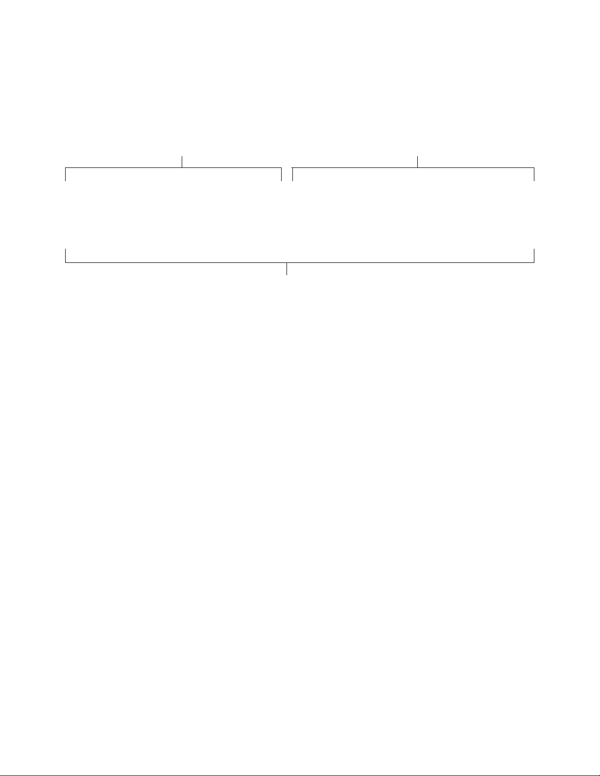
Model Number Nomenclature
Base Model Number Individual Module Model Numbers
Identifies the main unit features and options. Identifies module configurations, features and
options.
M2-H-011-R-2-A-A-0-C-0
Complete Model Number
A complete unit model number consists of a
base model number followed by a series of
individual module numbers. In the
individual module model number, the three
numbers after the three letter Module ID
indicate the position of the module in unit
assembly, increasing in value from the
:
MBH-101-A-00-00000-00000-0-0
FTA-102-P-A0-00000-00000-0-0
SFA-103-F-B0-A000C-00000-0-0
CLF-104-C-00-210F0-410F0-0-0
SFA-105-0-AA-CPTB0-00000-0-0
PEC-201-K-BI-A0000-00000-0-0
FTE-203-P-B0-00000-00000-0-0
return/outside air section to the discharge air
section and from the bottom to the top. In
the above example, the cooling coil module,
CLF-104-C-00-CPTB0-00000-0-0, would
be the fourth module on the bottom row of
the unit.
13
Page 14
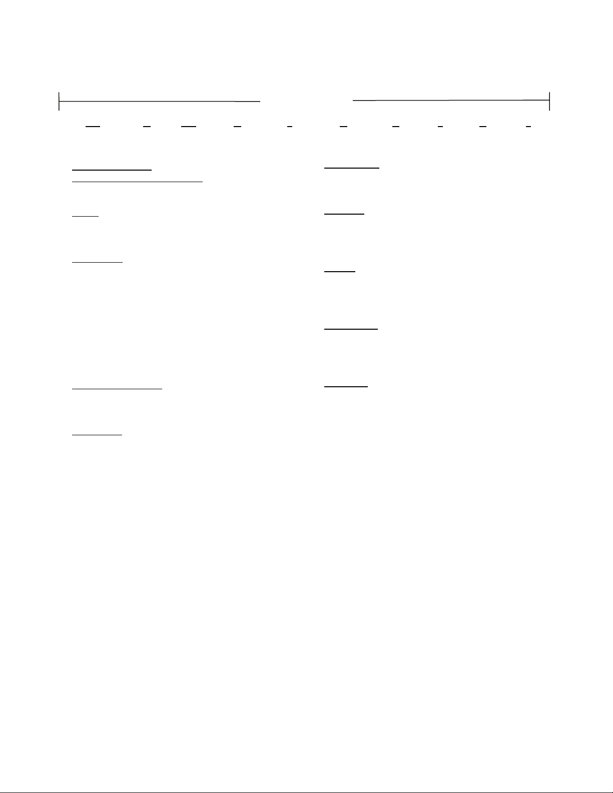
r
M2
Series and
Generation
H
-
Type
011
-
Unit
Size
BASE MODEL
SERIES AND GENERATION
M2 = Modular 2
TYPE
H = Horizontal
V = Vertical
UNIT SIZE
005 = 5 ft
008 = 8 ft
011 = 11 ft2 Coil
014 = 14 ft2 Coil
018 = 18 ft
022 = 22 ft
026 = 26 ft
032 = 32 ft
036 = 36 ft
SUPPLY AIRFLOW
L = Left Hand
R = Right Hand
VOLTAGE
1 = 230V/1Φ/60Hz
2 = 230V/3Φ/60Hz
3 = 460V/3Φ/60Hz
4 = 575V/3Φ/60Hz
6 = 380-415V/3Φ/50Hz
7 = 265V/1Φ/60Hz
8 = 208V/3Φ/60Hz
9 = 208V/1Φ/60Hz
2
Coil
2
Coil
2
Coil
2
Coil
2
Coil
2
Coil
2
Coil
nd
Generation
M2 Base Model Description
Model Numbe
R
-
Supply
Airflow
-
2
Voltage Assembly Wiring Paint
A
-
ASSEMBLY
A = Factory Assembled
B = Loose Boxes
WIRING
0 = None
A = Control Wiring in Fan Box
B = Control Wiring in Control Box
PAINT
0 = None
A = Standard White Exterior
B = Special Color Exterior
BASE RAIL
B = 8” High
C = 6” High
D = 10” High
SPECIAL
0 = None
A = Special Pricing Authorization
A
-
0
-
C
-
Base
Rail
-
0
Special
14
Page 15
Fan Module Description
r
SFA
Module ID Position
MODULE ID
SFA = Belt Driven Supply, Control Panel
SFB = Vertical Belt Driven Supply, Control Panel
SFC = Belt Drive Supply, Top Discharge, Control
Panel
SFD = Belt Driven Supply, No Control Panel
SDB = Direct Drive Supply, Control Panel
SDD = Direct Drive Supply, Top Discharge, Control
Panel
PEA = Belt Driven Power Exhaust
PEC = Belt Driven Power Exhaust, Top Discharge
EDB = Direct Drive Power Exhaust
EDD = Direct Drive Power Exhaust, Top Discharge
RFA = Belt Driven Power Return
RDB = Direct Drive Power Return
POSITION
### = Level and Position of Module in Air Handling
Unit
MOTOR SIZE
E = 1 hp
F = 2 hp
G = 3 hp
H = 5 hp
J = 7.5 hp
K = 10 hp
L = 15 hp
M = 20 hp
N = 25 hp
BLOWER
0 = None
A = 15” Backward Curved Plenum
B = 18” Backward Curved Plenum
C = 22” Backward Curved Plenum
D = 27” Backward Curved Plenum
E = 30” Backward Curved Plenum
F = 33” Backward Curved Plenum
G = 37” Backward Curved Plenum
H = 24” Backward Curved Plenum
J = 15” BC Plenum - 50% Width
K = 18” BC Plenum - 30% Width
L = 2 x 18” Backward Curved Plenum
M = 2 x 22” Backward Curved Plenum
N = 2 x 24” Backward Curved Plenum
P = 2 x 27” Backward Curved Plenum
103
-
F
-
Motor
Size
B 0
-
Blower Isolation
Model Numbe
A 00 0C
-
Motor
Type
ISOLATION
I = Fan Isolation
- Rubber-in-Shear Isolation on 005, 008, 011 & 014
- Spring Isolation on 018, 022, 026, 032 & 036
MOTOR TYPE
A = Standard Efficiency 1760 rpm
B = Premium Efficiency 1760 rpm
C = Premium Eff. 1760 rpm with VFD
D = Premium Eff. 1760 rpm with VFD and Bypass
E = Premium Efficiency 1170 rpm
F = Premium Eff. 1170 rpm with VFD
BLANK
00 = Standard
PULLEYS
## = Pulley Combination
SAFETY CONTROL
0 = None
A = Phase & Brownout Protection
BLANK
0000 = Standard
BLANK
0 = Standard
TYPE
0 = None
X = Special Pricing Authorization
Blank Pulleys
-
Control
0 0000
Safety
0
Blank Blank Type
-
0
-
15
Page 16
Filter Module Description
r
FTA
Module ID Position
MODULE ID
FTA = Small Flat Filter
FTC = Cartridge Filter
FTE = Medium Flat Filter
FTF = Large Flat Filter
FTG = G Flat Filter
FTH = Cartridge Filter with Flat Pre-Filter
FTI = I Flat Filter
FTK = Extra Large Flat Filter
POSITION
### = Level and Position of Module in Air Handling
Unit
FILTER TYPE
P = Pleated
C = Cartridge
FILTERS
A0 = 2” Pleated, 30% Eff.
B0 = 4” Pleated, 30% Eff.
C0 = 4” Pleated, 65% Eff. or 12” Cartridge, 65% Eff.
D0 = 4” Pleated, 85% Eff. or 12” Cartridge, 85% Eff.
E0 = 4” Pleated, 95% Eff. or 12” Cartridge, 95% Eff.
SAFETY CONTROL
0 = None
2 = Firestat
BLANK
0000 = Standard
102
-
P
-
Filter
Type
A0
-
Filters
Model Numbe
-
0 0000
Safety
Control
0 00 00
Blank
-
Filter
Type
Second
Filters
SECOND FILTER TYPE
Blank
-
Options
Second
0 = Type
C = Cartridge
SECOND FILTERS
C0 = 12” Cartridge, 65% Eff.
D0 = 12” Cartridge, 85% Eff.
E0 = 12” Cartridge, 95% Eff.
BLANK
00 = Standard
FILTER OPTIONS
0 = None
A = Magnehelic Gauge
B = Clogged Filter Switch
C = Magnehelic Gauge & Clogged Filter Switch
TYPE
0 = None
X = Special Pricing Authorization
0
Filter
0
-
Type
16
Page 17
Mixing Box Module Description
r
MBH
Module
ID
MODULE ID
MBA = Vertical Damper
MBB = Horizontal Top Damper
MBC = Vertical & Horizontal Top Damper
MBD = Vertical Damper with Filter
MBE = Horizontal Top Damper with Filter
MBF = Horizontal Bottom Damper
MBH = Vertical & Horizontal Bottom Damper
MBI = Horizontal Bottom Damper with Filter
MBJ = Vertical & Horizontal Top Damper with Filter
MBK = Vertical & Horizontal Bottom Damper with
Filter
POSITION
### = Level and Position of Module in Air Handling
Unit
ACTUATOR
0 = None
A = Two Position Actuator
B = DDC Actuator
FILTERS
00 = None
A0 = 2” Pleated, 30% Eff.
B0 = 4” Pleated, 30% Eff.
C0 = 4” Pleated, 65% Eff.
D0 = 4” Pleated, 85% Eff.
E0 = 4” Pleated, 95% Eff.
101
-
Position Position Filters
A
-
-
00
Model Numbe
0 0000
-
Safety
Control
0 0000
-
Blank
Bypass
Open
SAFETY CONTROL
0 = None
2 = Firestat
BLANK
0000 = Standard
BYPASS OPEN
0 = None
A = Top Open
B = Bottom Open
BLANK
0000 = Standard
FILTER OPTIONS
0 = None
A = Magnehelic Gauge
B = Clogged Filter Switch
C = Options A + B
TYPE
0 = None
X = Special Pricing Authorization
Blank
-
0
Filter
Options
0
-
Type
17
Page 18
PHA
r
Module
ID
MODULE ID
PHA = Electric Heat
PHB = Hot Water Coil
PHC = Hot Water Coil with Filter
PHD = Electric Heat with Filter
RHC = Hot Gas Reheat Coil
POSITION
### = Level and Position of Module in Air Handling
Unit
FUNCTION
H = Heating
D = Dehumidification
B = Heating and Dehumidification
FILTERS
00 = None
A0 = 2” Pleated, 30% Eff.
B0 = 4” Pleated, 30% Eff.
C0 = 4” Pleated, 65% Eff.
D0 = 4” Pleated, 85% Eff.
E0 = 4” Pleated, 95% Eff.
101
-
Position Function Filters Rows FPI Circuiting Coating kW Stages Blank
H
-
00
-
HEATING COIL
ROWS
1 = 1 Row
2 = 2 Rows
FPI
08 = 8 Fins Per Inch
10 = 10 Fins Per Inch
12 = 12 Fins Per Inch
CIRCUITING
F = Single Serpentine
H = Half Serpentine
COATING
0 = Standard
P = Polymer E-Coating
S = Stainless Steel Coil Casing
H = Stainless Steel Coil Casing & Copper Fins
Heat Module Description
Model Numbe
0 00 0 0
-
ELECTRIC HEAT
kW
A = 7 kW (5.25 kW)
B = 14 kW (10.5 kW)
C = 21 kW (15.75 kW)
D = 28 kW (21.0 kW)
E = 42 kW (31.5 kW)
F = 56 kW (42.0 kW)
G = 70 kW (52.5 kW)
H = 35 kW (26.25 kW)
J = 84 kW (63 kW)
K = 112 kW (84.0 kW)
L = 126 kW (94.5 kW)
M = 168 kW (126 kW)
N = 10 kW (7.5kW)
P = 20 kW (15 kW)
Q = 30 kW (22.5 kW)
R = 40 kW (30 kW)
S = 50 kW (37.5 kW)
T = 80 kW (60 kW)
U = 100 kW (75 kW)
V = 120 kW (90 kW)
W = 160 kW (120 kW)
STAGES
01 = 1 Stage
02 = 2 Stage
03 = 3 Stage
04 = 4 Stage
BLANK
00 = Standard
FILTER OPTIONS
0 = Standard
A = Magnehelic Gauge
B = Clogged Filter Switch
C = Options A + B
TYPE
0 = None
X = Special Pricing Authorization
E 02 00
-
-
0
Filter
Options
0
-
Type
18
Page 19
Blank Module Description
r
BBA
Module
ID
MODULE ID
BBA = Small
BBB = Medium
BBC = Large
BBD = XL
BBE = XXL
BBF = XXXL
CBA = Small with Drain Pan
CBB = Medium with Drain Pan
CBC = Large with Drain Pan
CBD = XL with Drain Pan
CBE = XXL with Drain Pan
CBF = XXXL with Drain Pan
POSITION
### = Level and Position of Module in Air Handling
Unit
DRAIN PAN TYPE
0 = None
A = Auxiliary
AIRWAY TYPE
AR = Top Open, Right Hand End Panel
AL = Top Open, Left Hand End Panel
-
101
Position
0
Drain
-
Pan
Type
-
AR
Airway
Type
Model Numbe
0 0000
-
Safety
Control
0 0000
-
Blank
SAFETY CONTROL
0 = None
2 = Firestat
BLANK
0000 = Standard
BYPASS OPENING
0 = None
A = Top Opening
B = Bottom Opening
BLANK
0000 = Standard
BLANK
0 = Standard
TYPE
0 = None
X = Special Pricing Authorization
Bypass
Opening
0
-
Blank Blank Type
0
-
19
Page 20
CBL
r
Module
ID
Coil Module Description
101
-
Position
MODULE ID
CBL = Chilled Water or DX
CLC = DX + Hot Gas Reheat
CLF = Hot Water + Chilled Water or DX
CLG = Electric Heat + Chilled Water or DX
CLI = Hot Water or Chilled Water Face Bypass
CLM = Chilled Water or DX, Optional Size
POSITION
### = Level and Position of Module in Air Handling
Unit
COOLING TYPE
0 = None
C = Chilled Water
D = DX
E = DX or Hot Gas Bypass
ELECTRIC HEAT
kW
A = 7 kW (5.3 kW)
B = 14 kW (10.5 kW)
C = 21 kW (15.8 kW)
D = 28 kW (21.0 kW)
H = 35 kW (26.3 kW)
E = 42 kW (35.0 kW)
F = 56 kW (42.0 kW)
G = 70 kW (52.5 kW)
J = 84 kW (47.7 kW)
K = 112 kW (53.0 kW)
L = 126 kW (58.3 kW)
M = 168 kW (63.6 kW)
STAGES
1 = 1 Stage
2 = 2 Stage
3 = 3 Stage
4 = 4 Stage
HEATING COIL
ROWS
1 = 1 Row
2 = 2 Rows
FPI
08 = 8 Fins Per Inch
10 = 10 Fins Per Inch
12 = 12 Fins Per Inch
-
C
Cooling
Type
0 0
-
kW Stages Rows FPI Circuiting Coating Rows FPI Circuiting Coating
-
Model Numbe
0 00 0 0
CIRCUITING
F = Single Serpentine
H = Half Serpentine
COATING
0 = Standard
P = Polymer E-Coating
S = Stainless Steel Coil Casing
H = Stainless Steel Coil Casing & Copper Fins
COOLING COIL
ROWS
4 = 4 Rows
6 = 6 Rows
8 = 8 Rows
FPI
08 = 8 Fins Per Inch
10 = 10 Fins Per Inch
12 = 12 Fins Per Inch
CIRCUITING
F = Single Serpentine
H = Half Serpentine
S = DX Single Circuit
I = DX Dual Circuit, Interlaced
COATING
0 = Standard
P = Polymer E-Coating
S = Stainless Steel Coil Casing
H = Stainless Steel Coil Casing & Copper Fins
DRAIN PAN
S = Stainless Steel
TYPE
0 = None
X = Special Pricing Authorization
4 10 F 0
-
S
-
Drain
Pan
0
-
Type
20
Page 21
Control Panel Module Description
r
Model Numbe
TRA
Module
ID
MODULE ID
TRA = Small
TRB = Medium
TRC = Large
TRD = XL
TRE = XXL
TRF = XXXL
POSITION
### = Level and Position of Module in Air Handling
Unit
BLANK
0 = Standard
BLANK
00 = Standard
101
-
Position Blank Blank
0
-
00
-
0 0000
-
Safety
Options
Blank Blank Blank Type
SAFETY OPTIONS
0 = None
2 = Firestat
BLANK
0000 = Standard
BLANK
00000 = Standard
BLANK
0 = Standard
TYPE
0 = None
X = Special Pricing Authorization
-
00000
0
-
0
-
21
Page 22
Energy Recovery Module Description
r
Model Numbe
HRA
Module
ID
MODULE ID
HRA = AAONAIRE Energy Recovery Wheel
POSITION
### = Level and Position of Module in Air Handling
Unit
WHEEL SIZE
A = Standard
BLANK
00 = Standard
101
-
Position
-
A
Wheel
Size
00
-
Blank Blank Blank Blank Type
-
00000
-
BLANK
00000 = Standard
BLANK
00000 = Standard
BLANK
0 = Standard
TYPE
0 = None
X = Special Pricing Authorization
00000
0
-
0
-
22
Page 23
Condenser Module Description
r
WCC
Module
ID
MODULE ID
WCC = Water-Cooled Condenser
WHP = Water-Source Heat Pump
POSITION
### = Level and Position of Module in Air Handling
Unit
COMPRESSOR TYPE
A = Scroll
B = Two Step
D = Variable Capacity Compressor
T = Tandem Compressors
TONNAGE
06 = 6 Ton Capacity
08 = 8 Ton Capacity
10 = 10 Ton Capacity
13 = 13 Ton Capacity
16 = 16 Ton Capacity
20 = 20 Ton Capacity
25 = 25 Ton Capacity
30 = 30 Ton Capacity
35 = 35 Ton Capacity
40 = 40 Ton Capacity
45 = 45 Ton Capacity
50 = 50 Ton Capacity
60 = 60 Ton Capacity
HEAT EXCHANGER TYPE
A = Copper Coaxial Heat Exchanger
B = Cupronickel Coaxial Heat Exchanger
C = Brazed Plate Heat Exchanger
-
101
Position
A
-
Compressor
Type
-
06
Tonnage
Model Numbe
-
Exchanger
A 000 A
Heat
Type
A 0000
-
Blank Glycol
BLANK
000= Standard
GLYCOL
A = 0-10%, Standard Heat Exchanger
B = 20-50%, Oversized Heat Exchanger
SAFETY CONTROL
A = WattMaster WSHP Control
C = Phase & Brown Out Protection
BLANK
0000 = Standard
SOUND BLANKET
0 = None
A = Special Pricing Authorization
TYPE
0 = None
X = Special Pricing Authorization
Safety
Control
Blank
-
0
Sound
Blanket
0
-
Type
23
Page 24
M2 Series
Typical Configurations
M2 Series units have been designed as
practical, high performance alternative to
expensive custom air handling equipment.
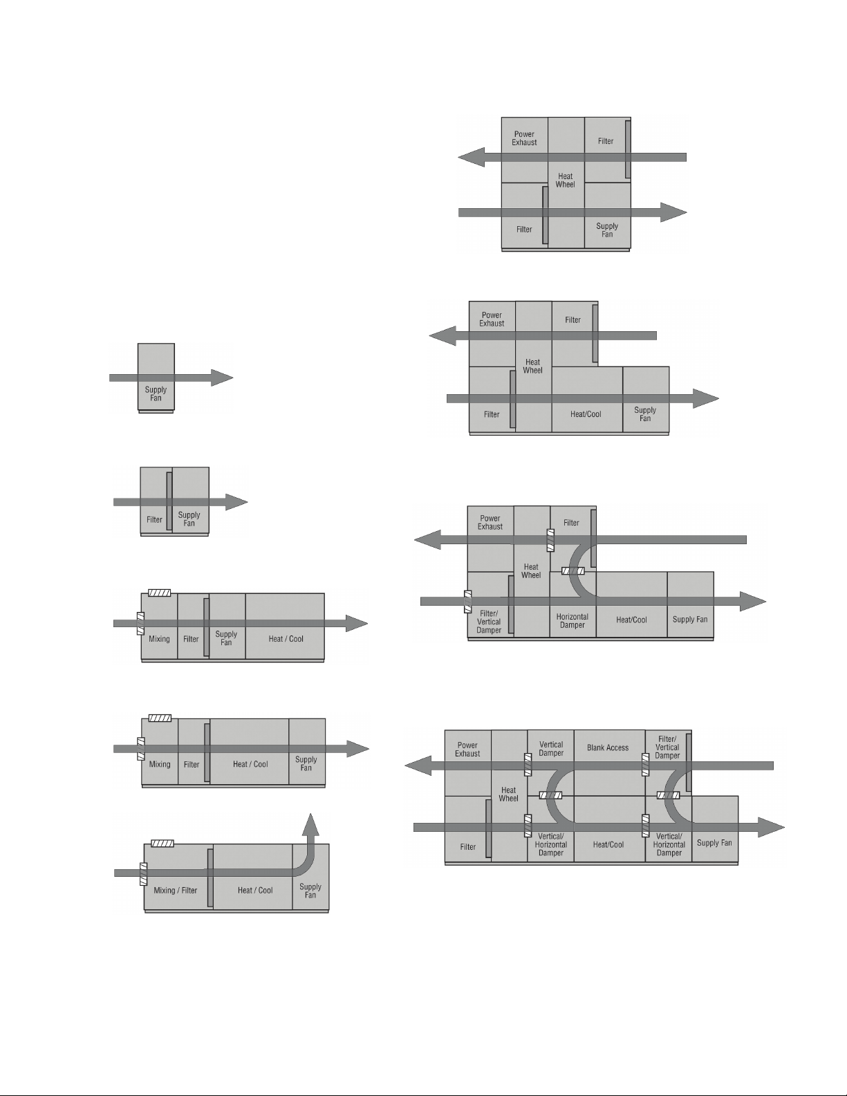
Figure 1 - Typical Configurations
Fan Only
AAONAIRE® (HRU)
Energy Recovery Unit
AAONAIRE®(HRU) with:
- DX or Chilled Water Cooling
- Hot Water, Steam or Electric Heat
Filter and Fan
Blow-Through
Draw-Through
Top Discharge
AAONAIRE®(HRU) with:
- DX or Chilled Water Cooling
- Hot Water, Steam or Electric Heat
- Outside Air and Return Air Mixing
AAONAIRE®(HRU) with:
- DX or Chilled Water Cooling
- Hot Water, Steam or Electric Heat
- Outside Air and Return Air Mixing
- Return Air Bypass
24
Page 25
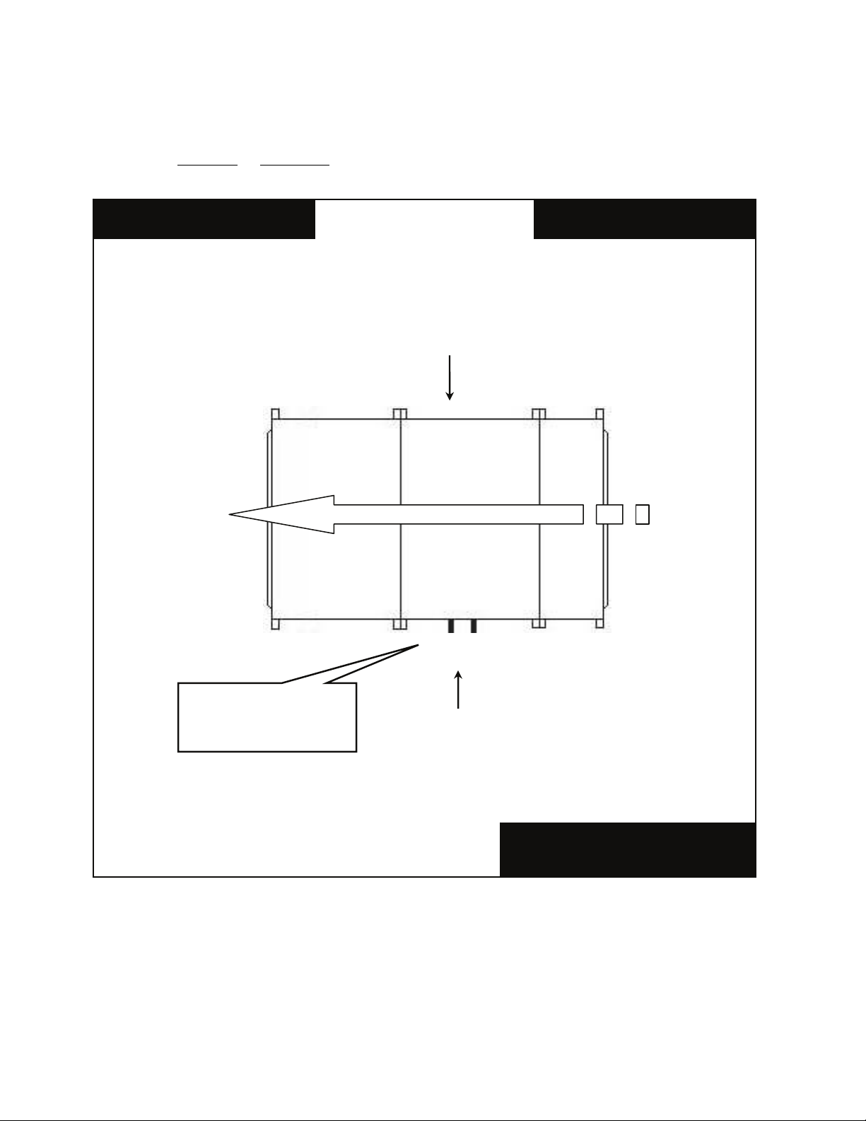
Unit Orientation
Determine left hand or right hand orientation/connections:
M2 Series Top View
Right Hand Side
Return Air Supply Air
Connections & service
access on left side for
left hand orientation
AIRFLOW
Filter Coil Supply Fan
Left Hand Side
Consider the airflow to be
hitting the back of your head.
Figure 2 - Unit Orientation
25
Page 26
General Information
M2 Series modular indoor air handling
units, modular outdoor air handling units,
self contained units and packaged rooftop
units have been designed for either indoor or
outdoor installation. Flexible connectors are
required on all duct connections to minimize
air leaks.
M2 Series units are designed for safe
operation when installed, operated and
maintained within design specifications and
the instructions in this manual. It is
necessary to follow these instructions to
avoid personal injury or damage to
equipment or property during equipment
installation, startup, operation and
maintenance.
Improper installation, adjustment,
alteration, service, or maintenance
can cause property damage,
personal injury or loss of life.
Installation and service must be
performed by a trained, qualified
installer or service agency. A copy of
this IOM should be kept with the unit.
These units must not be used as a
“construction heater” at anytime
during any phase of construction.
Very low return air temperatures,
harmful vapors, and misplacement of
the filters will damage the unit and its
efficiency.
This equipment is protected by a
standard limited warranty under the
condition that initial installation,
service, startup and maintenance is
performed according to the
instructions set forth in this manual.
This manual should be read in its
entirety prior to installation and
before performing any service or
maintenance work.
Equipment described in this manual
is available with many optional
accessories. If you have questions
after reading this manual in its
entirety, consult other factory
documentation or contact your AAON
Sales Representative to obtain
further information before
manipulating this equipment or its
optional accessories
Certification of Gas Heat Models
a. Certified as a Category III forced air
furnace with or without cooling.
b. Certified for indoor and outdoor
installation.
c. Certified for installation on a
combustible roof with a minimum of 12”
high curb.
Certification of Steam or Hot Water Heat
Models
a. Certified as a forced air heating system
with or without cooling.
b. Certified for indoor and outdoor
installation.
Certification of Electric Heat Models
a. Certified as an electric warm air furnace
with or without cooling.
b. Certified for indoor and outdoor
installation only.
26
Page 27
c. Certified for installation on a
combustible roof with a minimum of 12”
high curb.
Certification of Cooling Models
a. Certified as a commercial central air
conditioner with or without electrically
operated compressors.
b. Certified for indoor and outdoor
installation only.
c. Certified for installation on a
combustible roof with a minimum of 12”
high curb.
d. Certified with refrigerant R-410A coils
or with chilled water cooling coils.
Codes and Ordinances
System should be sized in accordance with
the American Society of Heating,
Refrigeration and Air Conditioning
Engineers Handbook.
Installation of M2 Series units must conform
to the ICC standards of the International
Mechanical Code, the International Building
Code, and local building, plumbing and
waste water codes. In the absence of local
codes installation must conform to the
current (United States) National Fuel Gas
Code ANSI-Z223.1/NFPA 54 or the current
(Canada) National Fuel & Propane
Installation Code CSA B149.1 or B149.2,
and Mechanical Refrigeration Code CSA
B52. All appliances must be electrically
grounded in accordance with local codes, or
in the absence of local codes, the current
National Electric Code, ANSI/NFPA 70 or
the current Canadian Electrical Code CSA
C22.1.
The Clean Air Act of 1990 bans the
intentional venting of refrigerant as of
July 1, 1992. Approved methods of
recovery, recycling, or reclaiming
must be followed.
Coils and sheet metal surfaces
present sharp edges and care must
be taken when working with
equipment.
Failure to observe the following
instructions will result in premature
failure of your system and possible
voiding of the warranty.
Receiving Unit
When received, the unit should be checked
for damage that might have occurred in
transit. If damage is found it should be noted
on the carrier’s freight bill. A request for
inspection by carrier’s agent should be made
in writing at once. Nameplate should be
checked to ensure the correct model sizes
and voltages have been received to match
the job requirements.
If repairs must be made to damaged goods,
then the factory should be notified before
any repair action is taken in order to protect
the warranty. Certain equipment alteration,
repair, and manipulation of equipment
without the manufacturer’s consent may
void the product warranty. Contact the
AAON-Longview Warranty Department for
assistance with handling damaged goods,
repairs, and freight claims: (903) 236-4403.
Note: Upon receipt check shipment for
items that ship loose such as filters and
remote sensors. Consult order and shipment
documentation to identify potential looseshipped items. Loose-shipped items may
have been placed inside unit cabinet for
security. Installers and owners should secure
27
Page 28
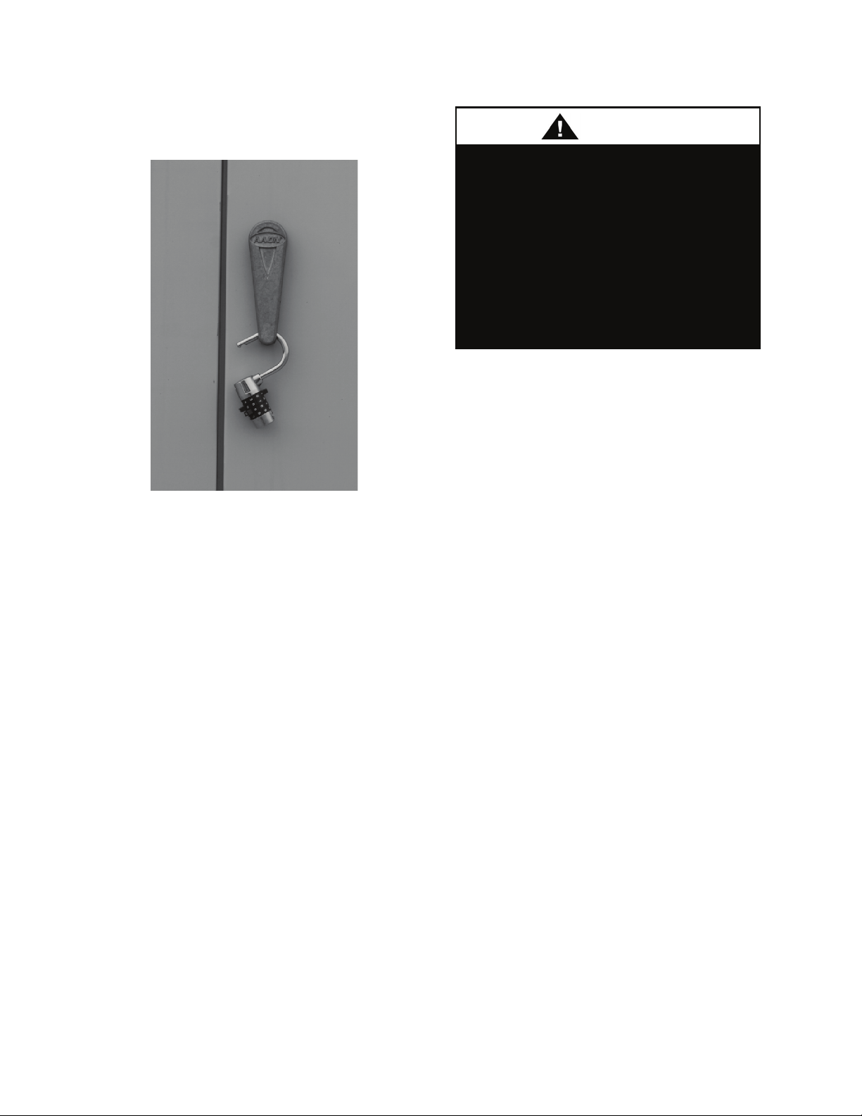
all doors with locks or nuts and bolts to
prevent unauthorized access.
Figure 3 - Lockable Handle
The warranty card must be completed in full
and returned to AAON not more that 3
months after unit is delivered.
Storage
If installation will not occur immediately
following delivery, store equipment in a dry
protected area away from construction
traffic and in the proper orientation as
marked on the packaging with all internal
packaging in place. Secure all loose-shipped
items.
Packaged Direct Expansion (DX) Units
All DX refrigeration systems are factory
assembled, leak tested, charged with
refrigerant, and run tested.
All DX refrigerant systems include an
evaporator, condenser, liquid line filter
driers, thermal expansion valves (TXV) and
scroll compressors. Compressors are
equipped with a positive pressure forced
lubrication system.
Some units are equipped with
compressor crankcase heaters,
which should be energized at least
24 hours prior to cooling operation, to
clear any liquid refrigerant from the
compressors.
CRANKCASE HEATER
OPERATION
Never cut off the main power supply to the
unit, except for servicing, emergency, or
complete shutdown of the unit. When power
is cut off from the unit crankcase heaters
cannot prevent refrigerant migration into the
compressors. This means the compressor
will cool down and liquid refrigerant may
accumulate in the compressor. The
compressor is designed to pump refrigerant
gas and damage may occur when power is
restored.
If power to the unit must be off for more
than an hour, turn the thermostat system
switch to "OFF", or turn the unit off at the
control panel, and leave the unit off until the
main power switch has been turned on again
for at least 24 hours for units with
compressor crankcase heaters. This will give
the crankcase heater time to clear any liquid
accumulation out of the compressor before it
is started.
Always control the unit from the thermostat,
or control panel, never at the main power
supply, except for servicing, emergency or
complete shutdown of the unit.
During the cooling season, if the air flow is
reduced due to dirty air filters or any other
reason, the cooling coils can get too cold
which will cause excessive liquid to return
28
Page 29
to the compressor. As the liquid
concentration builds up, oil is washed out of
the compressor, leaving it starved for
lubrication.
The compressor life will be seriously
shorted by reduced lubrication and the
pumping of excessive amounts of liquid oil
and refrigerant.
Note: Low Ambient Operation
Air-cooled DX units without a low ambient
option, such as condenser fan cycling, ECM
driven condenser fans or the 0°F low
ambient option, will not operate in the
cooling mode of operation properly when
the outdoor temperature is below 55°F. Low
ambient and/or economizer options are
recommended if cooling operation below
55°F is expected.
Gas or Electric Heating
The unit is designed to heat a given amount
of air while operating. If this amount of air
is greatly reduced, approximately 1/3 during
the heating season, the gas heat exchanger or
electric heating coil may overheat, and may
cut the burner or heater off entirely by action
of the safety high temperature limit devices
which are factory mounted at the heat
exchanger and supply fan areas.
Airflow should be adjusted after installation
to obtain an air temperature rise within the
range specified on the unit rating plate at the
required external static pressure.
Should overheating occur with a gas heat
exchanger, or the gas supply fail to shut off,
shut off the manual gas valve to the furnace
before shutting off the electrical supply.
Prolonged overheating of the heat exchanger
will shorten its life.
If unit has not been selected as a 100%
outside air unit (make up air unit) the return
air duct must be sealed to the unit and the
return air temperature must be maintained
between 55°F and 80°F.
Wiring Diagrams
Unit specific wiring diagrams are laminated
and affixed inside the controls compartment
door.
Condensate Drain Pan
Unit requires drain traps to be connected to
the condensate drain pan of the unit.
For condensate drain lines, the line should
be the same pipe size or larger than the drain
connection, include a p-trap, and pitch
downward toward drain. An air break should
be used with long runs of condensate lines.
Unit should not be operated without a
p-trap. Failure to install a p-trap may
result in overflow of condensate
water.
An auxiliary / emergency drain pan is
recommended for all indoor
applications where there is a risk of
water damage to surrounding
structure or furnishings. Refer to local
codes.
29
Page 30
Installation
AAON equipment has been designed for
quick and easy installation.
Improper installation, adjustment,
alteration, service, or maintenance
can cause property damage,
personal injury or loss of life.
Installation and service must be
performed by a trained, qualified
installer or service agency. A copy of
this IOM should be kept with the unit.
Locating Units
Verify rooftop, foundation or mounting
frame can support the total unit weight,
including accessory weights.
Before setting the unit into place, caution
must be taken to provide clearance for unit
doors that must be accessible for periodic
service. These areas contain the controls,
safety devices, refrigerant or water piping,
shut-off valves and filters.
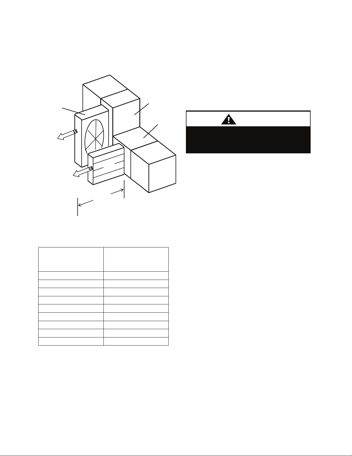
A minimum clearance equal to the width of
the unit is required on the access panel side
of the unit to ensure there is enough room to
slide out coils and energy recovery wheels,
and to access filters, fans and other internal
components.
Depending on natural gas and propane
heating module orientations, the combustion
air inlets or vent (flue) gas discharges may
be located in the unit roof or sides. There
must be 6 feet of clearance between these
roofs/sides and building walls, parapets,
adjacent buildings, or equipment. If
equipment is for replacement and required
clearances are not available, contact AAON
for recommendations.
When locating gas fired units, it is
recommended the unit be installed so
that the flue discharge vents are
located at least 120 inches away
from any opening through which
combustion products could enter the
building.
Distances from adjacent public
walkways, adjacent buildings,
operable windows and building
openings, shall conform to local
codes and/or the National Fuel Gas
Code, ANSI Z223.1/NFPA 54, or the
National Gas & Propane Code, CSA
B149.1
For gas fired unit, do not position flue
opening to discharge into a fresh air intake
of any other piece of equipment. Unit should
also be installed so that the flow of
combustion intake air is not obstructed from
reaching the furnace.
Outdoor vent opening must not be blocked
by snow. A minimum 12” curb must be used
or the vent outlet shall be greater than 12”
off the ground/roof.
Flue gas is dangerously hot and contains
containments. The user is responsible for
determining if vent gases may degrade
building materials.
The National Gas and Propane Installation
Code, B149.1 specifies a 6 ft. horizontal
vent terminal clearance to gas and electric
meters and relief devices.
30
Page 31
Local codes may supersede or further place
CAUTIO
restrictions on vent termination locations.
Energy
Recovery
Wheel
Coil
X
Energy
Recovery
Wheel
Module
Coil Module
Fan
Figure 4 - Service Access Clearance
Table 1 - Minimum Clearances
Minimum Required
Unit Size
Service Clearance
X =
M2-005 50”
M2-008 50”
M2-011 62”
M2-014 62”
M2-018 84”
M2-022 84”
M2-026 84”
M2-032 96”
M2-036 96”
Lifting the Unit
Units may be delivered in separate module
components or completely factory
assembled with all modules connected. In
the latter case, if the unit was received fully
assembled on a skid, then the equipment
should be lifted into place using the shipping
skid to prevent damage to the modules.
Incorrect lifting can cause damage to
the unit.
N
If cables or chains are used to hoist the unit
they must be the same length. Care should
be taken to prevent damage to the cabinet,
coils and condenser fans.
Before lifting unit, be sure that all shipping
material has been removed from unit. Secure
hooks and cables at all lifting points / lugs
provided on the unit.
Hoist unit to a point directly above the duct
openings.
Carefully lower and align the unit with
utility and duct openings. Make sure the unit
is properly seated and level.
Refer to the following unit lifting figures.
31
Page 32
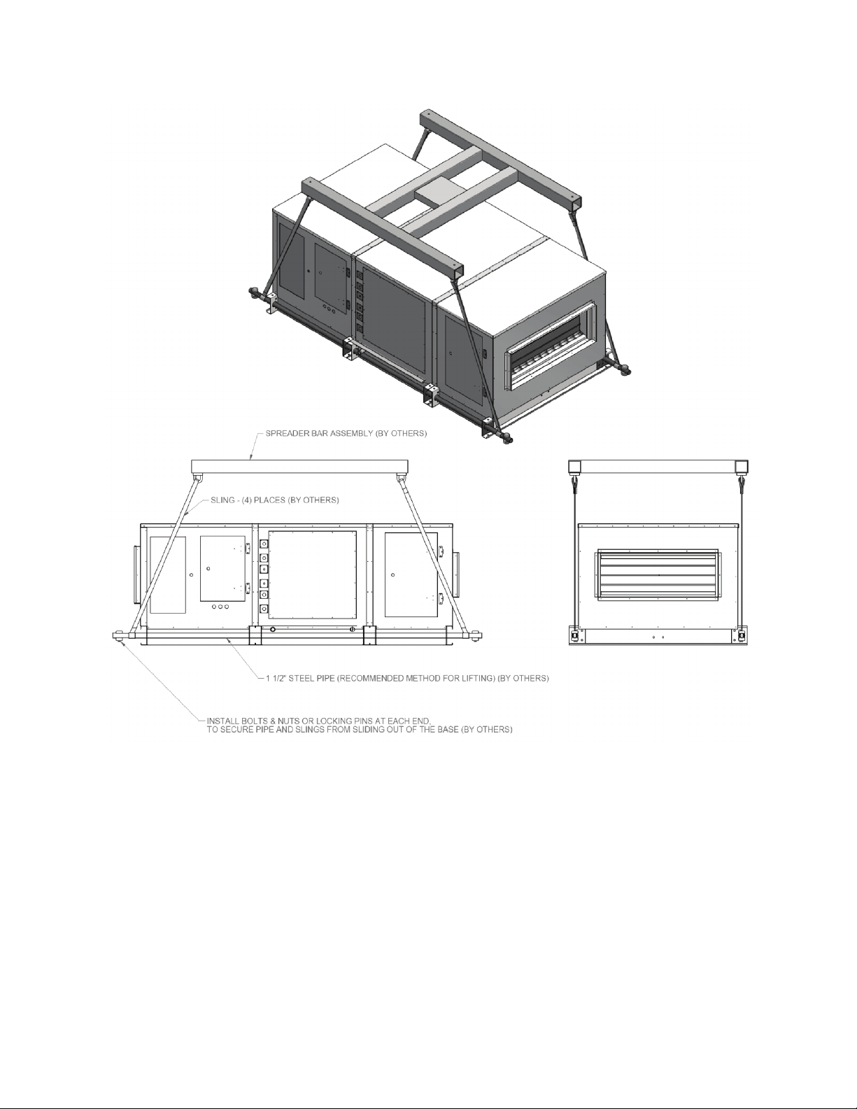
32
Figure 5 - M2 Series Unit Four Point Lifting
Page 33

Figure 6 - M2 Series Unit Eight Point Lifting
33
Page 34

Indoor Floor Mounted Units
Indoor M2 Series units can be floor
mounted.
Dual path units, self contained units and
units over size M2-014 must be floor
mounted. Make sure the unit is level, and
installed with a minimum height of 6” to
allow for proper drainage of the condensate
line. Other installation provisions may be
necessary according to job specifications.
Indoor Suspended Units
Indoor M2 Series units can be can be
suspended. Only single path units of size
M2-005 to M2-014 should be suspended.
Suspension of dual path units, self contained
units or units over size M2-014 is not
recommended.
A ceiling suspended mounting frame must
be provided for unit suspension. It is the
responsibility of the engineer or installing
contractor to design and build a suitable
structure based on the load distribution of
individual modules. C-channels, or similar
structural members, are suggested to be
placed parallel to airflow under each base
rail of the unit, with appropriate structural
cross members as required by weight and
design. A 4” minimum c-channel size is
recommended. The unit is not designed to be
suspended directly from the base rails. An
appropriate structural support is required for
suspension.
The air handling unit must be installed level
as the internal drain pan is manufactured
with a slope toward the drain. Other
installation provisions may be necessary
according to job specifications and
requirements.
Cross members
perpendicular to airflow
Figure 7 - Unit Suspension
Supports positioned
under base rails
parallel to airflow
Ceiling/roof
structure
Suspension
lines or rods
Base rail
Field supplied
support structure
Suspension lines or rods
tied to support structure
(not to the unit base rail)
34
Page 35

Module Assembly
Although M2 Series modular units are
shipped factory assembled as standard, they
may be ordered unassembled for certain
applications such as for assembly in existing
structures where modules must be
manipulated separately. If the unit was
ordered unassembled, then you will need to
connect the modules in the field.
Locate the configuration schematic in the
equipment’s literature packet. The schematic
will have CONFIGURATION written in the
top left hand corner followed by the unit
model number and then the module
configuration numbers listed in order.
1. Identify and Situate Modules
Use the Model Number descriptions at the
beginning of this manual for assistance
identifying module types by their three-letter
codes.
It is advisable to situate all required modules
in the installation location as near as
possible to the order in which they will be
connected. Be sure to leave enough space to
work between modules before connection.
Bulb gasket will be applied in the next step.
Identify each module by the configuration
number on its label. For example, if a
module has a configuration number of FTF101-P-A0-00000-00000-0-0, then it is a
large flat filter module “FTF”, and should be
placed in the first position “101” of the
lower tier - the bottom left as you face the
access side of a right hand unit, or the
bottom right as you face the access side of a
left hand unit.
Although you should have a schematic
available, the configuration numbers have
been created so that correct assembly order
can be determined without the need for a
schematic.
Modules are arranged in order with 100
series modules on the first tier and 200
series modules on the second tier. Module
101 will always be located on the end of the
bottom tier - the bottom left as you face the
access side of a right hand unit, or the
bottom right as you face the access side of a
left hand unit. Module 201 will always be
located on the end of the top tier - the top
left as you face the access side of a right
hand unit, or the top right as you face the
access side of a left hand unit. Therefore, it
is possible to identify the exact module
arrangement even without knowing the
module type, and without a configuration
schematic.
If, for any reason, you are unable to identify
a module or its position in the final
assembly, then consult the project engineer
or AAON sales representative.
After identifying modules and determining
module arrangement you can prepare the
modules for assembly.
35
Page 36

CONFIGURATION:
M2-H-011-R-2-A-A-0-C-0
FTF-101-P-A0-00000-00000-0-0
HRA-102-A-00-00000-00000-0-0
CLF-103-C-00-210F0-610F0-S-0
SFA-104-K-C0-A0000-00000-0-0
PEC-201-K-BI-A0000-00000-0-0
FTE-203-P-B0-00000-00000-0-0
Module
configuration
numbers
Table provides required
service access clearances
for applicable modules
201
Note: Energy recovery wheel
module will have a 100 series
number, but will span both tiers,
also utilizing a 200 series space.
101
Figure 8 - Module Assembly Schematic
Base model
number
PEC FTE
Configuration Schematic can
be found in unit literature packet
Arrows
indicate
airflow
203
HRA
CLF FTF SFA
104
102
103
36
Page 37

2. Apply Bulb Gasket
The bulb gasket material creates an airtight
seal between adjacent modules after
connection. The adhesive backing is initially
low tack so the gasket can be easily
repositioned during installation. The
adhesive backing will cure to full bond
strength after 72 hours and will then no
longer be easily removable.
Figure 9 - Bulb Gasket
Apply bulb gasketing
around entire perimeter
of airway opening
Figure 10 - Applying Bulb Gasket
Each joint in the unit body should have
gasket applied to one side
of the opening
separation. That is, only one airway opening
of two adjacent modules should have a
gasket applied.
Apply bulb gasket to one side of the
opening between adjacent modules
Figure 11 - Gasket Application
3. Connect Modules
Modules are to be connected with nuts and
bolts through the base rail and with metal
strapping over module joints. Metal straps
have adhesive backs and are to be
additionally fastened to the unit case with
sheet metal screws. All connection hardware
is shipped with the unit.
Align modules, and insert bolts through the
bolt holes in the base rails of two adjacent
modules. Secure with nuts to pull the bases
of the two modules together tightly.
Figure 12 - Bolted Base Rail
Use bar clamps or other non-destructive
winching device to pull the tops of the
modules together tightly.
You should now have a fully gasketed,
airtight joint that needs to be permanently
secured into position.
37
Page 38

A
A
Figure 13 - Bar Clamp
You should now have a fully gasketed,
airtight joint that needs to be permanently
secured into position.
4. Secure Module Joints
The metal straps are to be used to secure
module joints in order to maintain the
airtight seal. Straps are provided with predrilled holes and adhesive backing already
affixed. Self-tapping sheet metal screws are
provided to attach the straps to the unit
cabinet.
Leave bar clamps in place until strap is
secure.
Peel away backing from adhesive side of a
strap.
Place the strap over a module joint with the
adhesive side of the strap against the unit
case.
Ensure that strap completely covers the joint
and that it is square with the unit casing.
Apply pressure to the strap to affix the
adhesive and to hold strap in place.
Insert self-tapping screws through predrilled holes in strap and secure screws into
unit casing using a power drill. For best
results, use the lowest effective power drill
torque setting. Be careful not to over tighten
the screws.
Remove bar clamps and repeat for all
remaining module joints.
5/16” Hex Head
Self-Tapping Screws
Provided with Unit
1”
Figure 14 - Self-Tapping Screw
Top
Strap
Side
Strap
Angle
Strap
Figure 15 - Strap Types
Top
Strap
Side
Strap
ngle
Strap
Figure 16 - Strap Locations
ngle
Strap
38
Page 39

Put straps in position,
hold in place and attach
with self-tapping sheet
metal screws.
Figure 17 - Strap Installation
5. Run Power and Control Wiring
M2 Series units are equipped with an
internal wiring chase, located along the
inside top of each module. Wire is provided
for power and control wiring inside the unit.
Wire from the unit to external controls and
power sources must be provided in the field.
A color-coded wiring diagram is laminated
and affixed to the inside of the control
compartment access door. M2 Series units
are equipped with a single point power
connection.
6. Final Sealing
It is very important to keep air from
infiltrating the unit cabinet. Seal all piping
penetrations with Armaflex, Permagum or
other suitable sealant. Also seal around drain
connections, electrical connections and all
other inlets where air may enter the cabinet.
This is especially important when the unit is
installed in an unconditioned area.
Refrigerant Piping
(See back of the manual for refrigerant
piping diagrams and connection sizes.)
Piping from the condensing unit to the air
handling unit is the responsibility of the
installing contractor.
The Split System Configurator
or
Refrigerant Piping Calculator in
AAONEcat32 should be used to determine
acceptable refrigerant line sizes.
The pipe sizes must be selected to meet the
actual installation conditions and not simply
based on the connection sizes at the
evaporator or condensing unit.
Improper installation, adjustment,
alteration, service or maintenance
can cause property damage,
personal injury or loss of life.
Installation and service must be
performed by a trained, qualified
installer. A copy of this IOM should
be kept with the unit.
39
Page 40

CAUTIO
This section is for information only
and is not intended to provide all
details required by the designer or
installer of the refrigerant piping
between the condenser or
condensing unit and the air handling
unit. AAON is not responsible for
interconnecting refrigerant piping.
Consult ASHRAE Handbook –
Refrigeration and ASME Standards.
N
Only clean ACR tubing should be used.
Piping should conform to generally accepted
practices and codes.
The air handling unit coils are pressurized.
The copper caps must be punctured to
permit a gradual escape of the pressure prior
to un-sweating those caps. Immediately
couple the tubing to the indoor unit to avoid
exposing the coils to moisture. A properly
sized filter drier is furnished in the
condenser. When making solder
connections, make sure dry nitrogen flows
through the lines, when heating the copper,
to prevent oxidization inside of the copper.
When piping is completed
interconnecting piping and air handling
unit must be evacuated to 500 microns or
less and leak checked. Condenser shutoff
valves can then be opened to allow
refrigerant to flow to the air handling unit.
Thermal expansion valve bulbs should be
mounted with good thermal contact on a
horizontal section of the suction line close to
the evaporator, but outside the cabinet, and
well insulated.
Refrigerant lines should be fastened and
supported according to local codes.
Unit should be charged based on
determination of sub-cooling and superheat.
See Adjusting Refrigerant Charge section
for more information.
Refrigerant reheat coil for the modulating
hot gas reheat option is factory installed.
Liquid line receiver should be installed at
the condensing unit. Care must be taken not
to cross circuits in reheat systems.
Modulating Hot Gas Reheat Piping:
1. Run a hot gas reheat line from the
condensing unit and connect it to the inlet of
the stub-out on the reheat coil. The inlet
connection is the top (or highest) stub-out of
the reheat coil. Connect the hot gas line
from the outdoor unit to the upper stub-out
connection of the reheat coil.
2. Run a liquid line from the discharge of the
reheat coil through a tee connection. Run a
liquid line from the condenser, through a
check valve to the other side of the tee. Run
a liquid line from the tee to the liquid line
stub-out of the evaporator coil.
3. Run a suction line from the evaporator
coil outlet stub-out to the condensing unit.
Determining Refrigerant Line Size
Line sizes must be selected to meet
actual installation conditions, not
simply based on the connection sizes
at the condensing unit or air handling
unit.
The piping between the condenser and low
side must ensure:
1. Minimum pressure drop, and
2. Continuous oil return, and
3. Prevention of liquid refrigerant slugging,
or carryover
40
Page 41

Minimizing the refrigerant line size is
favorable from an economic perspective,
reducing installation costs, and reducing the
potential for leakage. However, as pipe
diameters narrow, pressure-reducing
frictional forces increase.
Excessive suction line pressure drop causes
loss of compressor capacity and increased
power usage resulting in reduced system
efficiency. Excessive pressure drops in the
liquid line can cause the liquid refrigerant to
flash, resulting in faulty TXV operation and
improper system performance. In order to
operate efficiently and cost effectively,
while avoiding malfunction, refrigeration
systems must be designed to minimize both
cost and pressure loss.
Equivalent Line Length
All line lengths discussed in this manual,
unless specifically stated otherwise, are
Equivalent Line Lengths. The frictional
pressure drop through valves, fittings, and
accessories is determined by establishing the
equivalent length of straight pipe of the
same diameter. Always use equivalent line
lengths when calculating pressure drop.
Special piping provisions must be taken
when lines are run underground, up vertical
risers, or in excessively long line runs.
Liquid Line Sizing
When sizing the liquid line, it is important to
minimize the refrigerant charge to reduce
installation costs and improve system
reliability. This can be achieved by
minimizing the liquid line diameter.
However, reducing the pipe diameter will
increase the velocity of the liquid refrigerant
which increases the frictional pressure drop
in the liquid line, and causes other
undesirable effects such as noise.
Maintaining the pressure in the liquid line is
critical to ensuring sufficient saturation
temperature, avoiding flashing upstream of
the TXV, and maintaining system
efficiency. Pressure losses through the
liquid line due to frictional contact, installed
accessories, and vertical risers are
inevitable. Maintaining adequate subcooling at the condenser to overcome these
losses is the only method to ensure that
liquid refrigerant reaches the TXV.
Liquid refrigerant traveling upwards in a
riser loses head pressure. If the evaporator is
below the condenser, and the liquid line
does not include risers, the gravitational
force will increase the pressure of the liquid
refrigerant. This will allow the refrigerant to
withstand greater frictional losses without
the occurrence of flashing prior to the TXV.
A moisture-indicating sight glass may be
field installed in the liquid line to indicate
the occurrence of premature flashing or
moisture in the line. The sight glass should
not be used to determine if the system is
properly charged. Use temperature and
pressure measurements to determine
liquid sub-cooling, not the sight glass.
Liquid Line Routing
Care should be taken with vertical risers.
When the system is shut down, gravity will
pull liquid down the vertical column, and
back to the condenser when it is below the
evaporator. This could potentially result in
compressor flooding. A check valve can be
installed in the liquid line where the liquid
column rises above the condenser to prevent
this. The liquid line is typically pitched
along with the suction line, or hot gas line,
to minimize the complexity of the
configuration.
Liquid Line Insulation
When the liquid line is routed through
regions where temperature losses are
expected, no insulation is required, as this
41
Page 42

may provide additional sub-cooling to the
refrigerant. When routing the liquid line
through high temperature areas, insulation of
the line is appropriate to avoid loss of subcooling through heat gain.
Liquid Line Guidelines
In order to ensure liquid at the TXV,
frictional losses must not exceed available
sub-cooling. A commonly used guideline to
consider is a system design with pressure
losses due to friction through the line not to
exceed a corresponding 1-2°F change in
saturation temperature.
If the velocity of refrigerant in the liquid line
is too great, it could cause excessive noise or
piping erosion. The recommended
maximum velocities for liquid lines are 100
fpm from the condenser to a receiver tank to
discourage fluid backup, and 300 fpm from
receiver tank to the evaporator to minimize
valve induced liquid hammer.
Liquid Line Accessories
Liquid line shut off valves and filter driers
are factory provided. Filter driers must be
field installed on 2-6 ton units. The total
length equivalent of pressure losses through
valves, elbows and fittings must be
considered when adding additional
components in the field. It is a good practice
to utilize the fewest elbows that will allow
the mating units to be successfully joined.
Suction Line Sizing
The suction line is more critical than the
liquid line from a design and construction
standpoint. More care must be taken to
ensure that adequate velocity is achieved to
return oil to the compressor at minimum
loading conditions. However, reducing the
piping diameter to increase the velocity at
minimal load can result in excessive
pressure losses, capacity reduction, and
noise at full load.
Suction Line Routing
Pitch the suction line in the direction of flow
(about 1 foot per 100 feet of length) to
maintain oil flow towards the compressor,
and keep it from flooding back into the
evaporator. Crankcase heaters are provided
to keep any condensed refrigerant that
collects in the compressor from causing
damage or wear. Make sure to provide
support to maintain suction line positioning,
and insulate completely between the
evaporator and condensing unit.
It is important to consider part load
operation when sizing suction lines. At
minimum capacity, refrigerant velocity may
not be adequate to return oil up the vertical
riser. Decreasing the diameter of the vertical
riser will increase the velocity, but also the
frictional loss.
Circuits with variable capacity scroll
compressors require suction riser
traps every 10 feet.
A double suction riser can be applied to the
situation of part load operation with a
suction riser. A double suction riser is
designed to return oil at minimum load
while not incurring excessive frictional
losses at full load. A double suction riser
consists of a small diameter riser in parallel
with a larger diameter riser, and a trap at the
base of the large riser. At minimum
capacity, refrigerant velocity is not sufficient
to carry oil up both risers, and it collects in
the trap, effectively closing off the larger
diameter riser, and diverting refrigerant up
the small riser where velocity of the
refrigerant is sufficient to maintain oil flow.
At full load, the mass flow clears the trap of
oil, and refrigerant is carried through both
42
Page 43

risers. The smaller diameter pipe should be
sized to return oil at minimum load, while
the larger diameter pipe should be sized so
that flow through both pipes provides
acceptable pressure drop at full load.
Suction Line Insulation
The entire suction line should be insulated.
This prevents condensation from forming on
the line, and reduces any potential loss in
capacity associated with heat gain.
Suction Line Guidelines
For proper performance, suction line
velocities less than a 4,000 fpm maximum
are recommended. The minimum velocity
required to return oil is dependent on the
pipe diameter, however, a general guideline
of 1,000 fpm minimum may be applied.
In a fashion similar to the liquid line, a
common guideline to consider is a system
design with pressure losses due to friction
through the line not to exceed a
corresponding 1-2°F change in saturation
temperature.
At points where small pipe size can be used
to provide sufficient velocity to return oil in
vertical risers at part loads, greater pressure
losses are incurred at full loads. This can be
compensated for by over sizing the
horizontal runs and vertical drop sections.
This will however require additional
refrigerant charge.
Circuits with variable capacity scroll
compressors require suction riser traps every
15 feet.
Suction Line Accessories
If the job requirements specify suction
accumulators, they must be separately
purchased and field installed.
Hot Gas Bypass Line
Hot Gas Bypass is available for use with DX
systems that may experience low suction
pressure during the operating cycle. This
may be due to varying load conditions
associated with VAV applications or units
supplying a large percentage of outside air.
The system is designed to divert refrigerant
from the compressor discharge to the low
pressure side of the system in order to keep
the evaporator from freezing and to maintain
adequate refrigerant velocity for oil return at
minimum load.
Hot discharge gas is redirected to the
evaporator inlet via an auxiliary side
connector (ASC) to false load the evaporator
when reduced suction pressure is sensed.
Field piping between the condensing unit
and the evaporator is required.
Hot Gas Bypass Piping Considerations for
Evaporator above Condensing Unit
Pitch the hot gas bypass (HGB) line
downward in the direction of refrigerant
flow, toward the evaporator.
When installing hot gas bypass risers, a
drain leg must be provided at the lowest
point in the system. The drain leg must be
vertical, its diameter should be the same as
the diameter of the riser, and it should be 1
foot long. Install a sight glass in the drain
leg for observation. Run an oil return line,
using 1/8 inch capillary tube, 10 feet in
length, from the drain leg to the suction line.
Connect the oil return line below the sight
glass and 1 inch above the bottom of the
drain leg.
HGB valves are adjustable. Factory HGB
valve settings will be sufficient for most
applications, but may require slight
adjustments for some applications, including
some make up air applications.
43
Page 44

Insulate the entire length of the HGB line
with a minimum 1 inch thick Armaflex
insulation.
Hot Gas Bypass Piping Considerations for
Evaporator below Condensing Unit
The line must slope downward from the
HGB valve toward the evaporator.
Hot Gas Bypass Line Guidelines
Choose a small size line to ensure oil return,
and minimize refrigerant charge.
Maintain velocities below a maximum of
4,000 fpm. A general minimum velocity
guideline to use is approximately 1,000 fpm.
Hot Gas Reheat
The AAON modulating hot gas reheat
system diverts hot discharge gas from the
condenser to the air handling unit through
the hot gas line. Field piping between the
condensing unit and the air handler is
required.
The line delivers the hot discharge gas to the
reheat coil and/or the hot gas bypass valve,
so it is sized as a discharge line.
Discharge lines should be sized to ensure
adequate velocity of refrigerant to ensure oil
return, avoid excessive noise associated with
velocities that are too high, and to minimize
efficiency losses associated with friction.
Pitch the hot gas line in the direction of flow
for oil return.
When installing hot gas reheat risers, a drip
leg must be provided at the lowest point in
the system. The drip leg must be vertical, its
diameter should be the same as the diameter
of the riser, and it should be 1 foot long. Run
a drip line, using 1/8 inch capillary tube, 10
feet in length, from the drip leg to the
suction line. Connect the drip line a
minimum of 1-inch above the bottom of the
drain leg.
Insulate the entire length of the hot gas line
with a minimum 1 inch thick Armaflex
insulation.
Hot Gas Reheat Guidelines
Maintain velocities below a maximum of
3,500 fpm. A general minimum velocity
guideline is 2,000 fpm.
Water-Cooled Condenser
Condenser water pump, condenser water
piping, cooling tower, pressure gauges,
strainers and all components of the
waterside piping must be field installed.
Open Loop Applications
This product contains one or more
refrigerant-to-water heat exchangers made
of 316 Stainless Steel. 316 Stainless Steel is
subject to severe corrosion and failure when
exposed to chlorides.
OPEN LOOP APPLICATIONS
Failure of the condenser as a result
of chemical corrosion is excluded
from coverage under AAON Inc.
warranties and the heat exchanger
manufacturer’s warranties.
Do not allow water containing any form of
chlorides to enter this heat exchanger.
Common forms of chlorides include:
1. Sea water mist entering an open cooling
tower system.
2. Contaminated make-up water containing
salt water.
44
Page 45

3. Disinfection the water loop with solutions
containing sodium hypochlorite.
Chlorides will result in a premature failure
of the condenser.
Failure of the condenser as a result of
chemical corrosion is excluded from
coverage under AAON warranties and the
heat exchanger manufacturer warranties.
Failure of the condenser will allow water to
enter the refrigerant circuit and will cause
extensive damage to the refrigerant circuit
components. Any damage to the equipment
as a result of condenser failure from
chemical corrosion due the fluid in the
condenser is excluded from coverage under
AAON warranties and the heat exchanger
manufacturer warranties.
OPEN LOOP APPLICATIONS
SMO 254 brazed plated refrigerantto-water heat exchangers are
recommended with all open loop
applications. Failure to use a SMO
254 heat exchanger may result in
premature failure of your system and
possible voiding of the warranty.
Cleaning the cooling tower or
condenser water loop with harsh
chemicals such as hydrochloric acid
(muriatic acid), chlorine or other
chlorides, can damage the
refrigerant-to-water heat exchanger.
Care should be taken to avoid
allowing chemicals to enter the
refrigerant-to-water heat exchanger.
See Appendix A - Heat Exchanger
Corrosion Resistance for more
information.
Freezing Water in the Heat Exchanger
This product contains one or more
refrigerant-to-water heat exchangers. A
refrigerant-to-water heat exchanger contains
refrigerant in one passage and water in
another passage. Water is subject to freezing
at 32°F. When water freezes in a heat
exchanger significant forces are exerted on
the components of the heat exchanger where
the water is confined.
Failure of the condenser due to
freezing will allow water to enter the
refrigerant circuit and will cause
extensive damage to the refrigerant
circuit components. Any damage to
the equipment as a result of water
freezing in the condenser is excluded
from coverage under AAON
warranties and the heat exchanger
manufacturer warranties.
WATER FREEZING
Unit is capable of operating with Entering
Water Temperatures (EWT) as low as 50°F
during heat pump heating mode without the
45
Page 46

need for head pressure control. If the EWT
is expected to be lower than 50°F or more
stable operation is desired, a field provided
water regulating valve may be used.
Glycol solution should be used if ambient
temperatures are expected to fall below
freezing or if the loop water temperature is
below 50°F while operating in the heating
mode (heat pump units only). Adding glycol
to condenser water causes an increase in
pressure drop resulting in a decrease in unit
performance. A minimum concentration of
20% glycol solution is recommended.
Table 2 - Glycol Freezing Points
% Glycol Ethylene
Glycol
Propylene
Glycol
20 18°F 19°F
30 7°F 9°F
40 -7°F -6°F
50 -28°F -27°F
Water loop piping runs through unheated
areas or outside the building should be
insulated.
Water Piping
Installing contractor must ensure a
differential pressure switch is installed
between the condenser water supply and
return connections. This sensor provides a
signal to the unit controller that water flow
is present in the heat exchanger and the unit
can operate without damaging unit
components.
Prior to connection of condensing
water supply, verify water pressure is
less than maximum pressure shown
on unit nameplate. To prevent injury
or death due to instantaneous
release of high pressure water, relief
valves should be field supplied on
water piping. Supply water
connection may require a backflow
preventer to prevent supply makeup
water from backing up into the public
water system.
WATER PRESSURE
Condenser water connections range in size
from 1-18”-4” OD copper or black pipe.
Only use approved water pipe material.
Avoid using galvanized material for water
lines/fittings as the material is corrosive and
may cause fouling of the water system.
Condenser water pump must be field sized
and installed between the cooling tower and
self contained unit. System should be sized
in accordance with the ASHRAE Handbook.
Use engineering guidelines to maintain
equal distances for supply and return piping
and limit bend radiuses to maintain balance
in the system. Balancing valves, permanent
thermometers and gauges may be required.
46
Page 47

CAUTIO
CAUTIO
Follow national and local codes when
installing water piping. Connections
to the unit should incorporate
vibration eliminators to reduce noise
and vibration and shutoff valves to
facilitate servicing. Supply and return
water piping must be at least as large
as the unit connections and larger
depending on length of runs, rise and
bends.
WATER PIPING
N
PVC (Polyvinyl Chloride) and CPVC
(Chlorinated Polyvinyl Chloride) are
vulnerable to attack by certain
chemicals. Polyolester (POE) oils
used with R-410A and other
refrigerants, even in trace amounts,
in a PVC or CPVC piping system will
result in stress cracking of the piping
and fittings and complete piping
system failure.
N
Before connection to the unit the condenser
water system should be flushed to remove
foreign material that could cause condenser
fouling. Install a screen strainer with a
minimum of 20 Mesh ahead of the
condenser inlet to prevent condenser fouling
and internal tube damage.
Mineral content of the condenser water must
be controlled. All make-up water has
minerals in it and as the water is evaporated
in the cooling tower, these minerals remain.
As the mineral content of the water
increases, the conductivity of the water
increases.
Field provided and installed water treatment
program must be compatible with stainless
steel, copper, aluminum, ABS plastic, and
PVC. Batch feed processes should never be
used as concentrated chemicals can cause
corrosion. Never use hydrochloric acid
(muriatic acid) or chlorine as it will corrode
stainless steel.
Each heat exchanger is equipped
with a refrigerant pressure relief
device to relieve pressure should
excessive condensing pressures
(>675 psig) occur. Codes may
require installing contractor to
connect and route relief piping
outdoors. The relief valve has a 5/8”
male flare outlet connection.
Unit is capable of operating with Entering
Water Temperatures (EWT) as low as 50°F
without the need for head pressure control.
If the EWT is expected to be lower than
50°F or more stable operation is desired, a
field provided water regulating valve may be
used.
Glycol solution should be used if ambient
temperatures are expected to fall below
freezing or if the loop water temperature is
below 50°F while operating in the heating
mode (heat pump units only). Adding glycol
to condenser water causes an increase in
pressure drop resulting in a decrease in unit
performance. A minimum concentration of
20% glycol solution is recommended.
47
Page 48
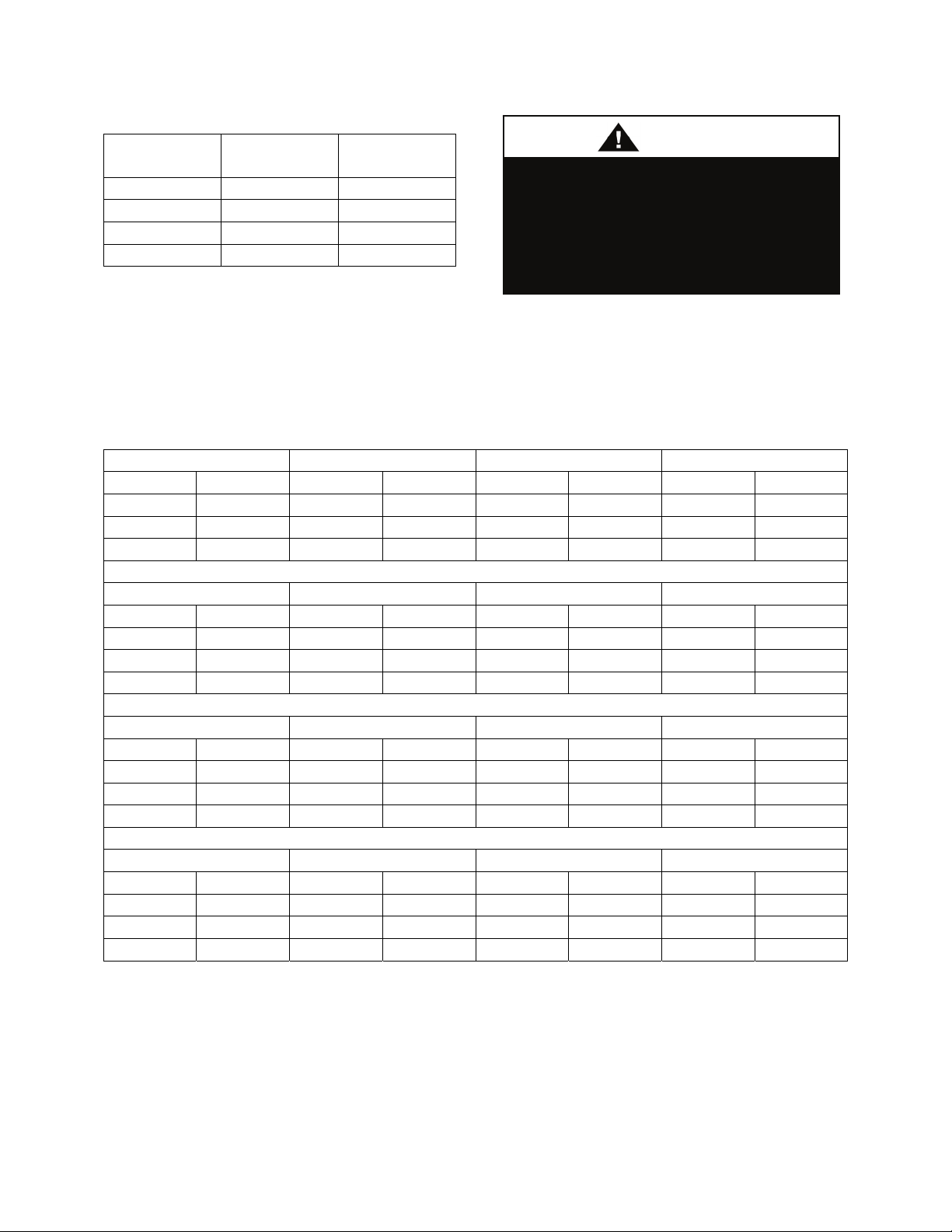
Table 3 - Freezing Points
CAUTIO
% Glycol Ethylene
Glycol
Propylene
Glycol
20 18°F 19°F
30 7°F 9°F
40 -7°F -6°F
50 -28°F -27°F
Do not exceed recommended
condenser fluid flow rates shown in
above table. Serious damage to or
erosion of the heat exchanger tubes
could occur.
N
Piping systems should not exceed 10 ft/sec
velocity to ensure tube wall integrity and
reduce noise.
Table 4 - Coaxial Heat Exchanger Pressure Drops (WCC- & WHP-)
-002 -003 -004 -005
gpm psi gpm psi gpm psi gpm psi
3 1.9 6 2.3 8 3.3 7 1.6
5 4.3 8 3.7 10 4.8 11 2.8
7 7.4 10 5.3 12 6.7 15 4.6
-006 -008 -010 -013
gpm psi gpm psi gpm psi gpm psi
11 2.6 16 3.8 14 2 20 3.4
16 4.2 20 5.5 22 3.5 28 5.8
20 6.0 24 7.6 30 5.6 36 8.8
-016 -020 -025 -030
gpm psi gpm psi gpm psi gpm psi
28 3.6 28 2.3 40 3.9 56 4.1
36 5.3 44 3.9 56 6.6 72 6
44 7.8 60 6.1 72 10 88 8.9
-040 -050 -060
gpm psi gpm psi gpm psi
56 2.6 80 4.2 112 4.33
88 4.4 112 7.1 144 6.5
120 6.9 144 10.4 176 9.6
48
Page 49

Table 5 - Brazed Plate Heat Exchanger Pressure Drops (WCC- & WHP-)
-003 -004 -005 -006
gpm psi gpm psi gpm psi gpm psi
7.9 2.89 10.0 4.41 12.5 5.46 15 2.37
9.5 4.03 12.1 6.21 15.1 7.69 18.1 3.39
-006 -008 -010 -013
gpm psi gpm psi gpm psi gpm psi
17.5 3.17 20.0 2.91 25.0 3.34 32.5 4.3
21.1 4.55 24.1 4.71 30.2 4.79 39.2 6.17
-016 -020 -025 -030
gpm psi gpm psi gpm psi gpm psi
40.0 4.26 50.0 4.72 62.5 4.92 75.0 4.75
48.3 6.11 60.4 6.77 75.4 7.06 90.5 6.82
-040 -050 -060
gpm psi gpm psi gpm psi
100.0 6.6 125.0 10.1 150.0 9.46
120.7 9.5 150.9 14.4 181.0 13.6
Water-Cooled Condenser Safeties
Electronic freeze protection and water flow
safeties should be field installed or factory
provided. If the leaving water temperature
drops below 38°F or water flow has ceased
the 24VAC control circuit will be broken to
disable the cooling system.
Electrical
Verify the unit name plate agrees with
power supply. M2 Series units are provided
with single point power wiring connections.
Connection terminations are made to the
main terminal block. A complete set of unit
specific wiring diagrams, showing factory
and field wiring are laminated in plastic and
located inside the controls compartment
door.
Disconnect all electrical power
sources before servicing the unit.
More than one power source may be
All units require a field supplied electrical
provided. Failure to do so may result
overcurrent and short circuit protection.
in injury or death from electrical
Device must not be sized larger than the
shock or entanglement in moving
Maximum Overcurrent Protection (MOP)
parts.
shown on the unit nameplate.
Codes may require a disconnect switch be
within sight of the unit.
Note: Do not install the required field
installed overcurrent protection or
disconnect switch on the unit!
Electrical supply can enter through the
bottom or side of the controls compartment.
Entry must be field cut into panels of the
unit.
49
Page 50

A single point connection to a terminal
block is provided. Split units may require
connection between the units. High voltage
conductors should enter the control panel in
a separate opening and separate conduit than
24V low voltage conductors.
The foam insulation releases
dangerous fumes when it is burnt. Do
not cut a foam part with a cutting
torch or plasma cutter. Do not weld to
a foam filled part.
WARNING
Note: Locations for field cut electrical
entries are marked on the unit. Field cut
openings must be a minimum of 6 inches
away from all components and wiring to
prevent damage due to drilling or cutting.
To pass wires through the wall or roof of the
unit, a hole should be cut and conduit passed
through it. Use the following procedure to
cut a round hole in a foam panel.
Cutting Electrical Openings
1. Locate the placement of the hole. Be sure
that the conduit will not interfere with the
operation of any component or prevent
access of any door or removable panel.
2. Drill a pilot hole all the way through the
foam panel.
3. Using a hole saw cut the hole through the
metal on both sides of the foam part.
4. With a knife cut the foam out of the hole.
5. After the conduit is installed in the hole
caulk the entire perimeter of the hole on
both sides with an industrial grade silicone
sealant or a duct seal compound.
If a larger cut-out is needed for additional
duct connections not provided by the
factory, or for any other reason, it is very
important that the foam be completely
sealed. Insulation covers should be
fabricated from sheet metal to cover the
foam at the cut. The edges and corners that
are not covered should be sealed using
silicone caulking. If a reciprocating saw is
used to make the cut out, take care that the
metal skins of the foamed part do not
separate from the foam, this would result in
reduced structural integrity of the part.
Size supply conductors based on the unit
Minimum Current Ampacity (MCA) rating.
Supply conductors must be rated a minimum
of 75°C.
Protect the branch circuit in accordance with
code requirements. The unit must be
electrically grounded in accordance with
local codes, or in the absence of local codes,
the current National Electric Code,
ANSI/NFPA 70 or the current Canadian
Electrical Code CSA C22.1.
Wire power leads to the unit’s terminal
block or main disconnect. All wiring beyond
this point has completed at the factory.
Three phase voltage imbalance will
cause motor overheating and
premature failure.
Supply voltage must be within the min/max
range shown on the unit nameplate.
Available short circuit current should not
exceed the SCCR rating shown on the unit
nameplate.
Three phase voltage imbalance will cause
motor overheating and premature failure.
The maximum allowable imbalance is 2.0%.
Voltage imbalance is defined as 100 times
the sum of the deviation of the three
50
Page 51

voltages from the average divided by the
CAUTIO
average voltage.
Example:
(221V+230V+227V)/3 = 226V, then
100*(226V-221V)/226V = 2.2%, which
exceeds the allowable imbalance.
Check voltage imbalance at the unit
disconnect switch and at the compressor
terminal. Contact your local power company
for line voltage corrections.
Installing contractor must check for proper
motor rotation and check blower motor
amperage listed on the motor nameplate is
not exceeded. Motor overload protection
may be a function of the variable frequency
drive (VFD) and must not be bypassed.
Note: All units are factory wired for
208/230V, 460V, or 575V. If unit is to be
connected to a 208V supply, the transformer
must be rewired to 208V service. For 208V
service interchange the yellow and red
conductor on the low voltage control
transformer.
Red-Black for 208V
Yellow-Black for 230V
Rotation must be checked on all
MOTORS AND COMPRESSORS at
startup by a qualified service
technician. Scroll compressors are
directional and can be damaged if
rotated in the wrong direction.
Compressor rotation must be
checked using suction and discharge
gauges. Fan motor rotation should be
checked for proper operation.
Alterations should only be made at
the unit power connection
N
Wire control signals to the unit’s low
voltage terminal block located in the
controls compartment.
If any factory installed wiring must be
replaced, use a minimum 105°C type AWM
insulated conductors.
Thermostat Control Wiring
If a thermostat is used for unit control,
thermostat should be located on an inside
wall 4-5 feet above the floor where it will
not be subjected to drafts, sun exposure, or
heat from electrical fixtures of appliances.
Control wiring must deliver adequate
voltage to components to assure proper
operation. Control voltage returning from
controller circuit must be a minimum of 21
VAC. To assure proper wiring use the
following chart to determine the allowable
wiring distances.
Table 6 - Control Wiring
Wire Size (Stranded)
- Copper Conductors
Only
20 AWG 200 ft
18 AWG 350 ft
16 AWG 500 ft
14 AWG 750 ft
12 AWG 1250 ft
Total Wire Distance Allowable =
(Quantity of Control Wires) x
(Control Wire Distance)
Take the total wire distance allowable and
divide by the number of wires to be
connected. This indicates the distance
allowable for that size wire. The wiring to
the unit must not exceed the total wire
distance allowable. If the voltage at the
connectors is less than 21 VAC, isolation
relays must be installed. If under external
control 21 VAC must be field verified.
Total Wire Distance
Allowable
51
Page 52

All external devices must be powered via a
separate external power supply.
Example:
A total of 8 wires must be pulled 75ft to a
control the unit. What size wire should be
used?
According to the Table 2, 16 AWG allows
for 63ft (500 ft/8 wires) and 14 AWG allows
for 94ft (750 ft/8 wires). Thus, 14 AWG
should be used.
Condensate Drain Piping
Unit may be equipped with more than one
condensate drain pan connection. A p-trap
and drain line must be installed on every
drain connection, with the p-trap not to
exceed 6” from the drain connection. The
lines should be the same pipe size or larger
than the drain connection, include a p-trap,
and pitch downward toward drain. An air
break should be used with long runs of
condensate lines.
Unit should not be operated without
p-traps. Failure to install a p-traps
may result in overflow of condensate
water.
Draw-through cooling coils will have a
negative static pressure in the drain pan area.
This will cause an un-trapped drain to back
up due to air being pulled up through the
condensate drain piping. Blow-through coils
will have a positive static pressure in the
drain pan. The condensate piping on these
drain pans must be trapped to prevent
pressure loss through the drain.
Condensate drain trapping and piping should
conform to all applicable governing codes.
Note: The drain pan connection is a 1” MPT
fitting.
Figure 18 - Draw-Through Drain Trap
The X dimension on the draw-through trap
should be at least equal to the absolute value
of the negative static pressure in the drain
pan plus one inch. To calculate the static
pressure at the drain pan add the pressure
drops of all components upstream of the
drain pan, including the cooling coil, and
add the return duct static pressure. Include
the dirt allowance pressure drop for the
filters to account for the worst-case scenario.
The height from top of the bottom bend of
the trap to the bottom of the leaving pipe
must be at least equal to one half of the X
dimension. This ensures that enough water
is stored in the trap to prevent losing the
drain seal during unit startup
Note: The absolute value of the fan inlet
pressure will always be greater than or equal
to the absolute value of the static pressure in
the drain pan on draw-through units, so the
fan inlet pressure is a safe value to use for
the drain pan static pressure.
Table 7 - Drain Trap Dimensions
52
Page 53

Draw-Through
Drain Pan Pressure Trap Dimensions
Negative Static X X/2
(inches of water) (inch) (inch)
-0.50 1.50 0.75
-1.00 2.00 1.00
-1.50 2.50 1.25
-2.00 3.00 1.50
-2.50 3.50 1.75
-3.00 4.00 2.00
-3.50 4.50 2.25
-4.00 5.00 2.50
-4.50 5.50 2.75
-5.00 6.00 3.00
-5.50 6.50 3.25
-6.00 7.00 3.50
-6.50 7.50 3.75
-7.00 8.00 4.00
-7.50 8.50 4.25
-8.00 9.00 4.50
Figure 19 - Blow-Through Drain Trap
The Y dimension of blow-through traps
should be at least equal to the value of the
positive pressure in the drain pan plus one
inch. This ensures that there will be enough
water stored in the trap to counter the static
pressure in the drain pan. To find the
pressure subtract any pressure drops
between the drain pan and the supply blower
from the blower discharge pressure. The
worst-case scenario for blow-through coils
is the minimum pressure drop, so do not
include dirt allowance pressure drops for
filters.
The bottom of the leaving pipe should be at
least one half inch lower than the bottom of
the drain pan connection. This ensures
proper drainage when the unit is not
running.
Note: It may be necessary to fill the trap
manually, or the trap can be filled
automatically by operating the unit until
enough condensate collects to fill the trap.
The trap will then be filled when the unit is
turned off.
Table 8 - Blow-Through Drain Trap
Dimensions
Blow-Through
Drain Pan Pressure Trap Dimension
Positive Static Y
(inches of water) (inch)
0.5 1.5
1.0 2.0
1.5 2.5
2.0 3.0
2.5 3.5
3.0 4.0
3.5 4.5
4.0 5.0
4.5 5.5
5.0 6.0
5.5 6.5
6.0 7.0
6.5 7.5
7.0 8.0
7.5 8.5
8.0 9.0
Blower Wheels
AAON units are equipped with a backward
curved blower wheels that is set to deliver
the air volume specified according to unit
size and/or job requirements.
53
Page 54

Air Adjustment
In the event that reduced air volume is
required, an air volume band can be installed
within the blower wheel to reduce the
amount of air delivery. If the unit is factory
equipped with the air band but additional air
delivery is needed, the band can be removed
from the wheel.
The air band is sized according to the air
delivery specifications and can be ordered
from the factory for field installation.
The related photos of the wheel are provided
for practical guidelines only in order to
identify the air band location in the wheel.
Actual field installation of the air band into
the wheel will require access into and
through the blower wheel venturi.
The band is made of aluminum, sized and
equipped with easy bend tabs that are to be
inserted into pre-punched slots provided on
the wheel. Once the band has been inserted
into the slots, it MUST BE secured by
bending the tabs over from the back side of
the wheel and also MUST BE secured from
the inside by connecting the ends together
with a pop-rivet in the holes provided on the
ends of the band. If the band is to be field
installed, a hand held pop-rivet tool is
recommended for connecting the band ends
together. Caution must be taken to assure
that the band is tightly installed and no
damage, denting, or alteration to the wheel
or blades occurs during the installation.
54
Page 55

Figure 20 - Supply Fan Banding
Waterside Economizer
Pre-cooling waterside economizer coil is
supplied without water piping. A kit to pipe
the coil in series with the condenser water
circuit along with a valve which diverts
condenser water to the coil or around the
coil is optional.
During economizer mode cool water passes
through the economizer and condenser in
series. During standard cooling mode water
bypasses the economizer coil and passes
through the condenser.
A p-trap must be installed on the coil drain
outlet, not to exceed 6” from the drain
connection. See the previous section on
condensate drain piping for additional p-trap
and drain information.
DRAIN PAN CONNECTION
With a waterside economizer coil a
separate drain connection is
included. Failure to use this separate
drain connection may result in water
backup and overflow of drain pan.
55
Page 56

An aquastat is included with the field
installed water piping kit and is used to
modulate water flow through the
economizer coil. The controller is mounted
in the controls compartment. Electrical
connections must be field wired. The
temperature bulb requires field mounting.
Care should be taken to firmly mount the
bulb on the supply water piping, but not to
dent the bulb when installing. The aquastat
has a temperature calibration range
adjustment of -10°F to 100°F and must be
field set.
Mineral content of the condenser water must
be controlled. All make-up water has
minerals in it and as the water is evaporated
in the cooling tower, these minerals remain.
As the mineral content of the water
increases, the conductivity of the water
increases.
Field provided and installed water treatment
program must be compatible with stainless
steel, copper, aluminum, ABS plastic, and
PVC. Batch feed processes should never be
used as concentrated chemicals can cause
corrosion. Never use hydrochloric acid
(muriatic acid) or chlorine as it will corrode
stainless steel.
Hot Water and Steam Coils
Factory installed one or two row hot water
heating coils can be factory mounted. These
coils are supplied from a hot water source
through separate piping from the condenser
water source. All controls for heating
operation are field supplied and field
installed.
Always connect the supply to the top of the
coil and the return to the bottom. Water coils
should not be subjected to entering air
temperatures below 38°F to prevent coil
freeze-up. If air temperature across the coil
is going to be below this value, use a glycol
solution to match the coldest air expected.
Water supply lines must be insulated,
properly fastened, drained, and supported
according to local code requirements.
Air handling units with steam heating coils
MUST BE installed high enough to allow
for a minimum of 1 foot condensate drop leg
off of the steam coil, or as recommended by
the steam trap manufacturer. Lines should
be insulated with approved insulation and be
properly fastened, sloped, and supported
according to local code requirements.
Chilled Water Coils
Factory installed four or six row chilled
water cooling coils can be factory mounted.
These coils are supplied from a chilled water
source through separate piping from the
condenser water source. All controls for the
cooling coil are field supplied and field
installed.
Water supply lines must be insulated with
closed cell type pipe insulation or insulation
that includes a vapor barrier. Lines should
be properly fastened, drained and supported
according to local code requirements, and
job specifications.
Piping shall be in accordance with
national and local codes. Pressure
limiting devices, backflow preventers
and all other safety requirements are
the sole responsibility of the installing
contractor.
Electric Heating
Heating is accomplished by passing
electrical current through a specified amount
of resistance heaters which will produce the
56
Page 57

required heat. The indoor fan motor will
energize at the same time as the heaters.
Wiring to the air handling unit must be done
in accordance with local electrical codes and
standards. Check specified electrical rating
and install with proper wire size.
Gas Fired Duct Furnace
Improper installation, adjustment,
alteration, service, or maintenance
can cause property damage,
personal injury or loss of life.
Installation and service must be
performed by a trained, qualified
installer or service agency. A copy of
this IOM should be kept with the unit.
WARNING
Inspection on Arrival
1. Inspect unit upon arrival for any damage
that may have occurred during shipping.
2. Prior to installation locate rating plate and
verify that furnace is equipped for the
available fuel supply and power supply at
point of installation.
Unit Location and Clearances
1. Be sure unit is located with respect to
building construction and other equipment
to provide ready access and clearance to
access panels or doors that must be opened
to permit adjustment and servicing of the
heating module.
2. The heating unit provided is listed for
installation on the positive side of the
circulating air blower only.
3. Do not install unit where it may exposed
to potentially explosive or flammable
vapors.
4. Do not locate unit in areas where
corrosive vapors (such as chlorinated,
halogenated, or acidic) are present in the
atmosphere or can be mixed with
combustion air entering heater.
Outdoor Units
1. Provide at least 6 feet clearance to
roof/side of the unit, where the combustion
air inlet or vent (flue) gas discharge is
located, from walls, parapets or adjacent
buildings or equipment. If equipment is for
replacement and required clearances are not
available, contact unit manufacturer for
recommendations.
2. Unit must be installed with combustion
air openings located at least one (1) foot
above the average snow depth for the
location.
3. Do not locate unit near building
ventilators or exhausts, or areas where
corrosive chemical vapors can be drawn into
combustion air supply.
4. Do not install units in locations where
flue products can be drawn in the adjacent
building openings such as windows, fresh
air intakes, etc.
5. Be sure that vent discharge for flue gases
is directed away from combustion air inlet
and located to prevent flue products from
being drawn into combustion air supply.
Burner performance can be adversely
affected by recirculation of flue products.
Indoor Units
1. Locate unit to insure an adequate supply
of fresh air to replace air used in the
combustion and ventilation process.
2. When locating units, it is important to
consider the exhaust vent piping connected
to the outside atmosphere. Location should
57
Page 58
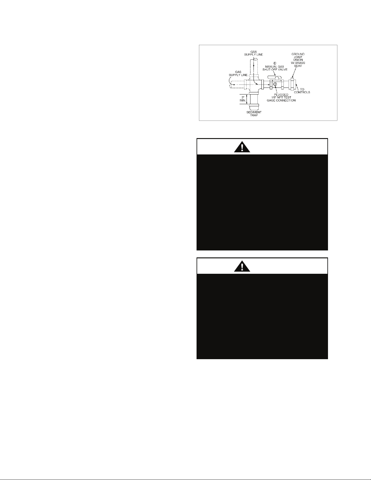
minimize the number of elbows or turns in
G
vent pipe.
Gas Supply, Piping and Connections
Gas piping must be installed in accordance
with local codes, or in the absence of local
code, installation must conform to the
current (United States) National Fuel Gas
Code ANSI-Z223.1/NFPA 54 or the current
(Canada) National Fuel & Propane
Installation Code CSA B149.1 or B149.2.
1. Gas piping must be sized for the total Btu
input of all units (heaters) serviced by a
single supply.
2. Be sure that gas regulators servicing more
than one heater have the proper pipe and
internal orifice size for the total input of all
heaters serviced by the regulator.
3. Duct furnaces require a minimum inlet
gas pressure of 5.0 “w.c and limited to a
maximum inlet gas pressure of 13.5” w.c.,
with the furnace operating.
4. A 1/8” NPT tap is provided on the inlet
side of the gas valve to the heater. A fitting
suitable for connection to a pressure gauge
capable of measuring gas pressure should be
connected to each heater serviced by a
single regulator so that gas pressure at each
heater can be measured with all heaters in
operation.
5. A drip leg (sediment trap) and a manual
shut off valve must be provided immediately
upstream of the gas control on the heating
unit. To facilitate servicing of unit,
installation of a union is recommended.
Figure 21 - Sediment Trap
1. All field gas piping must be
pressure / leak tested prior to
operation. NEVER use an open flame
to check for leaks. Use a soap
solution or other leak detecting
solution for testing.
2. Gas pressure to appliance controls
must never exceed 13.5” w.c. (1/2
psi)
WARNIN
1. When pressure testing at 1/2 psi or
less, close the manual shutoff valve
on the appliance before testing.
2. When pressure testing gas supply
line at 1/2 psi or higher, close manual
gas valve and disconnect heater from
supply line to be tested. Cap or plug
the supply line.
58
Page 59
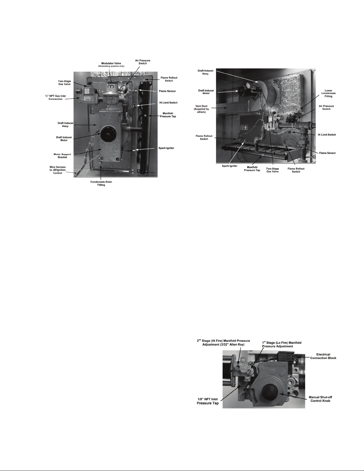
Duct Furnace Component Identification
Figure 22 - Horizontal Configuration
Horizontal Airflow Configuration
1. Airflow may be from either right or left
for heater as shown, without any difference
in system performance.
2. Typically no condensate drain attachment
is necessary in “Heat” only applications.
Condensation should not occur during
heating cycle. However, in applications
operating at low temperature rise or with
50% or more outside air, condensation may
occur early in the heating cycle. In these
applications connection of a condensate
drain line is recommended, to avoid
condensate buildup and possible heat
exchanger damage.
3. If heating section is located downstream
of a refrigeration system or cooling coil,
condensation can occur during operation of
the air conditioning, resulting in
condensation from warm, moist air in the
heat exchanger tubes and flue collector. This
condensate is not harmful to the heat
exchanger provided it is drained
continuously. For these applications a 1/4
inch NPT connection is provided for
attachment of condensate drain line to
remove condensate from heat exchanger.
Figure 23 - Vertical Configuration
Vertical Airflow Configuration
1. Airflow may be either upflow or
downflow for heater as shown, without any
difference in system performance.
2. In this configuration, condensate due to
operation of air conditioning system would
drain through the open heat exchanger tubes
near base of heater. An optional condensate
drain pan is available for these applications,
if none is incorporated integral to the unit.
3. Some condensation may occur in the flue
collector box, and it is recommended that a
drain tube be connected to the lower
condensate drain fitting as well.
Gas Valve
Figure 24 - Gas Valve
59
Page 60

Input
The correct heat capacity of the furnace is
controlled by the burner orifices and the gas
manifold pressure. The manifold pressure is
factory set, but should be checked at the
time of start-up.
Operating and Safety Instructions
1. This duct furnace does not have a pilot. It
is equipped with a direct spark ignition
device that automatically lights the gas
burner. DO NOT try to light burners by
hand.
2. BEFORE OPERATING, leak test all gas
piping up to heater gas valve. Smell around
the unit area for gas. DO NOT attempt to
place heater in operation until source of gas
leak is identified and corrected.
3. Use only hand force to push and turn the
gas control knob to the “ON” position.
NEVER use tools. If knob does not operate
by hand, replace gas valve prior to staring
the unit. Forcing or attempting to repair the
gas valve may result in fire or explosion.
4. Do not attempt to operate unit, if there is
indication that any part or control has been
under water. Any control or component that
has been under water must be replaced prior
to trying to start the unit.
Do not store or use gasoline or other
flammable vapors and liquids in the
vicinity of this or any other appliance.
Startup
1. Turn thermostat or temperature controller
to its lowest setting.
2. Turn off gas supply at the manual shut-off
valve (supplied by others).
3. Turn off power to the unit at the
disconnect switch.
4. Open door to unit module housing the gas
heater.
5. Move gas control knob to “Off” position.
6. Install a tapped fitting for attachment to a
manometer, or other gauge suitable for 14.0”
w.c., in the inlet pressure tap, and for 10.0”
w.c., in the manifold pressure tap.
7. Wait 5 minutes for any gas to clear out. If
you smell gas, turn off gas supply at the
manual shut-off valve (field installed). If
you don’t smell gas or have corrected any
leaks, go to the next step.
8. Turn gas control knob to “On” position.
9. Open all manual gas valves (supplied by
others).
10. Turn power on at disconnect switch.
11. Set thermostat or controller to its highest
position to initiate call for heat and maintain
operation of unit.
12. Draft inducer will run for a 15 to 30
second pre-purge period.
13. At the end of the pre-purge the direct
spark will be energized and gas valve will
open.
Check and Adjust Manifold Pressure
For 2 stage (TS) and modulating control
(MD) systems manifold pressure should be
1.2” w.c. Adjust Lo Regulator on 2 stage gas
valve, if necessary. The controls are design
to hold operation at this pressure for 2
minutes. After that time manifold pressure
should increase to 3.5” w.c. within 30 to 45
seconds.
60
Page 61

For On-Off units the manifold pressure
should be 3.5” w.c.
Failure to Ignite
1. For the initial start-up, or after unit has
been off long periods of time, the first
ignition trial may be unsuccessful due to
need to purge air from manifold at start-up.
2. If ignition does not occur on the first trial,
the gas and spark are shut-off by the ignition
control and the control enters an inter-purge
period of 15 to 90 seconds, during which the
draft inducer continues to run.
3. At the end of the inter-purge period,
another trial for ignition will be initiated.
4. Control will initiate up to three ignition
trials on a call for heat before lockout of
control occurs.
5. Control can be brought out of lockout by
turning thermostat or controller to its lowest
position and waiting 5 seconds and then
turning back up to call for heat. Some
controls provided will automatically reset
after one hour and initiate a call for heat.
Burner Flames
Prior to completing the start-up, check the
appearance of the main burner flame. See
Figure 34a and Figure 34b for flame
characteristics of properly adjusted natural
gas systems.
Figure 25 - 1.2” w.c. Manifold
Figure 26 - 3.5” w.c. Manifold
1. The burner flame should be
predominately blue in color and well defined
and centered at the tube entry as shown in
Figure 34a and Figure 34b. Distorted flame
or yellow tipping of natural gas flame, or a
long yellow flame on propane, may be
caused by lint and dirt accumulation inside
burner or at burner ports, at air inlet between
61
Page 62
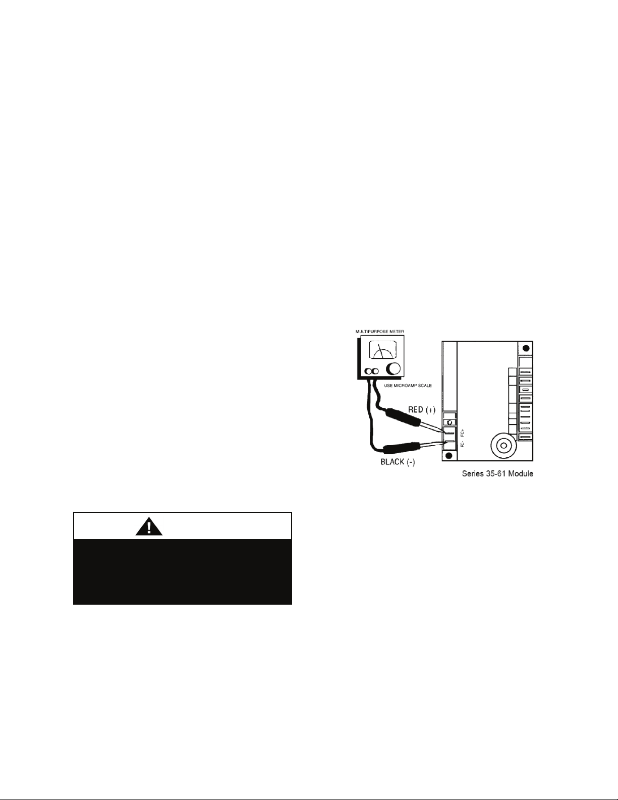
burner and manifold pipe, or debris in the
main burner orifice. Soft brush or vacuum
clean affected areas after performing
Shutdown procedure.
2. Poorly defined, substantially yellow
flames, or flames that appear lazy, indicate
poor air supply to burners or excessive
burner input. Verify gas supply type and
manifold pressure with rating plate.
3. Poor air supply can be caused by
obstructions or blockage in heat exchanger
tubes or vent discharge pipe. Inspect and
clean as necessary by to eliminate blockage.
Vacuum any dirt or loose debris found in the
tubes or vents. Clean heat exchanger tubes
with stiff brush after performing Shutdown
procedure. Poor flame characteristics can
also be caused by undersized combustion air
openings or flue gas recirculation into
combustion air supply. Increase air opening
size or re-direct flue products to prevent recirculation.
4. Reduced air delivery can also be the result
of fan blade slippage, dirt accumulation the
fan blade or low voltage to draft inducer
motor. Inspect draft fan assembly and be
sure fan blade is secure to motor shaft.
Check line voltage to heater.
Do not store or use gasoline or other
flammable vapors and liquids in the
vicinity of this or any other appliance.
Shutdown
1. Set thermostat or controller to lowest
setting.
2. Turn off electrical supply to unit at
disconnect switch.
3. Turn off manual gas supply (supplied by
others).
4. Disconnect manifold and inlet pressure
taps and re-install pipe plugs.
5. Close module door.
Normal Operation
1. Turn on electrical supply to unit at
disconnect switch.
2. Turn on manual gas supply (supplied by
others).
3. Set Thermostat or Temperature controller
to desired temperature.
Figure 27 - Flame Sensor Current Check
Service Checks
Flame current is the current which passes
through the flame from the sensor to ground.
The minimum flame current necessary to
keep the system from lockout is 0.7
microamps. To measure flame current,
connect an analog DC microammeter to the
FC- and FC+ terminals per figure. Meter
should read 0.7 uA or higher. If the meter
reads below “0” on scale, meter leads are
reversed. Disconnect power and reconnect
meter leads for proper polarity.
62
Page 63

Air Pressure Switch
An air pressure switch is provided as part of
the control system to verify airflow through
draft inducer by monitoring the difference in
pressure between the draft inducer and the
atmosphere. If sufficient negative pressure is
not present, indicating lack of proper air
movement through heat exchanger, the
switch opens shutting off gas supply though
the ignition control module. On units with
two speed draft inducer operation, a dual air
pressure switch is used, monitoring high and
low speed pressures. The air pressure
switches have fixed settings and are not
adjustable.
Rollout Switch (Manual Reset)
The duct furnace is equipped with manual
reset rollout switches in the event of burner
flame rollout. The switch will open on
temperature rise and shut-off gas supply
through the ignition control module. Flame
rollout can be caused by insufficient airflow
for the burner firing rate (high gas pressure),
blockage of the vent system or in the heat
exchanger. The duct furnace should not be
placed back in operation until the cause of
rollout condition is identified. The rollout
switch can be reset by pressing the button on
the top of the switch.
High Limit Switch
The duct furnace is equipped with a fixed
temperature high limit switch mounted on
the vestibule panel that shuts off gas to the
heater through the ignition control module in
the event of reduced circulating airflow over
the heat exchanger. Reduced airflow can be
caused by motor failure of the circulating air
blower, dirty or blocked filters or restriction
of the air inlet or outlet to the unit. The high
limit switch will automatically reset when
the temperature drops to 15ºF below the set
point. Determine the cause of the reduced air
flow and correct.
Ignition Control Diagnostics and Service
Guide (Fenwal 35-61 Series). LED flashes
on for ¼ second, and off for ¼ second
during fault condition. Pause between fault
codes is 3 seconds.
63
Page 64

Table 9 - Gas Heater Troubleshooting
LED
System Description Actions
Code
None No Power to
T1
Open Limit
Switch
Steady
On
1
Flash
Internal
Control Fault
(No Operation)
Combustion
Air Flow Fault
On call for heat nothing happens 1. Check for open fuse or circuit breaker.
Thermostat call for heat. No power
across terminals V1 / V2 control.
24VAC across Terminal 24VAC /
V2-Gnd when Thermostat calling for
heat
Pressure switch contacts in closed
position for 30 seconds with no
output to Combustion blower.
Remains in this mode with
combustion blower off.
Open pressure switch or flame
rollout switch when inducer (IND
terminal) is energized. If switch
remains open for more than 30
seconds after combustion blower is
energized, control will remain in this
mode with IND terminal (blower)
energized.
2. Check for poor wiring connection.
3. Check for failed 24V transformer.
1. Check for proper operation of circulating air
supply system and for air filter blockage.
2. Check manifold pressure when limit cools and
closes. Natural gas 3.5” w.c / LP gas 10.0” w.c.
3. Low combustion blower air output. Flue gas
temp exceeds 550ºF. Inspect for debris
accumulation, proper wheel attachment, and
proper voltage to blower.
Control fault – Replace ignition control.
1. Check for short in wiring to pressure switch.
2. Check pressure switch for closed contacts (with
leads disconnected).
3. Replace pressure switch
1. Failed Combustion blower.
2. Check connections and air tube from draft
inducer to air switch for leaks.
3. Check rollout switch manual reset - depress
reset.
4. Check supply tube from draft inducer housing
to pressure switches for condensate - drain line
and re-connect.
5. Check pressure switch for condensate
accumulation
6. Replace pressure switch
64
Page 65

Table 10 - Gas Heater Troubleshooting Continued
LED
Code
2
Flash
3
Flash
System Description Actions
Flame Fault
(No Call for
Heat)
Ignition
Lockout
Flame sense failure / flame present
with no call for heat.
Failure to light and or carryover.
Loss of flame or flame signal during
ignition or operation cycle.
Control will initiate up to 3 ignition
re-trials before lockout.
1. Check for voltage to gas valve with thermostat
in off position. Valve should not be powered.
2. If valve is not energized, check for gas flow
(manifold pressure reading greater than 0). If gas
flow, turn off main shut-off valve and replace gas
valve.
1. Verify gas supply available and operation of
gas valve - manifold pressure at start of ignition
cycle. Check for power to valve terminals LO &
COM while spark is energized.
2. Is spark present? - If not check igniter for debris
between electrodes, cracked ceramic and check
ignition wire for short to ground.
3. Check flame sensor wiring connections to
electrode and control and for any abrasions.
4. Check for cracked ceramic on flame sensor or
grounded sensor rod.
5. Verify that ample air supply and proper venting
of flue gases occurs during operating cycle.
6. Check for circulating air leaks into burner
compartment during operation.
7. Check for re-circulation of flue gases into
combustion air supply.
8. If all conditions satisfactory – replace ignition
control.
65
Page 66

Operating Control Systems
Two Stage (TN) - Low / High Fire / High
Speed Inducer Only
Modulating (MD) - Modulating (25 to
100%) / 2 Speed Draft Inducer - Mid-Fire
Start (55%)
Modulating (MH) - Modulating (25 to
100%) / 2 Speed Draft Inducer - High Fire
Start (100%)
Refer to unit wiring diagrams located in unit
door.
Furnace Maintenance
Improper installation, adjustment,
alteration, service or maintenance
can cause property damage,
personal injury or loss of life.
Installation and service must be
performed by a trained, qualified
installer. A copy of this IOM should
be kept with the unit.
Disconnect all electrical power
sources before servicing the unit.
More than one power source may be
provided. Failure to do so may result
in injury or death from electrical
shock or entanglement in moving
parts.
If any original wiring needs to be
replaced it must be replaced with
wiring materials suitable for 105ºC.
Label all wires prior to disconnection
when servicing unit. Wiring errors can
cause improper or dangerous
operation. Verify proper operation
after servicing.
Duct Furnace Inspection
1. The duct furnace should be inspected
annually by a qualified service agency. The
condition of the burners, heat exchanger,
draft inducer, vent system, operating
controls and wiring should be determined.
Check for obvious signs of deterioration,
accumulation of dirt and debris and any heat
or water related damage. Any damaged or
deteriorated parts should be replaced before
the unit is put back into service.
2. Clean burners, heat exchanger, draft
inducer and vent ducts with a soft brush or
vacuum.
3. Check Heat Exchanger for cracks. If any
are present, replace heat exchanger before
putting unit back into service.
4. Check the attachment point of the duct
furnace to the cabinet or ducts to verify that
they are air tight.
5. Check the automatic gas valve to insure
that the gas valve seat is not leaking.
Duct Furnace Operation Check
1. Turn on power to the unit and set
thermostat or heat controller to call for heat,
allowing duct furnace to operate.
66
Page 67

2. Check for proper start-up and ignition as
outlined in Start-Up section.
3. Check the appearance of the burner flame.
4. Check that the circulating air fan is
operating and verify the proper airflow
through duct furnace.
5. Return thermostat or heat controller to
normal setting.
Troubleshooting
Table 11 - Problems, Causes and Solutions
Problem Possible Cause Solutions
Frosted evaporator coil, low
suction pressure
Unit runs, but supplies warm air Loss of refrigerant
Compressor starts, but opens
high pressure control
High suction pressure, but low
superheat
Unit operates continuously Low refrigerant charge
Restricted air flow
Low fan speed
Reversed blower rotation
Low refrigerant charge
Faulty expansion valve element
Plugged filter-drier
Refrigerant over-charged
Air in condenser coil
Condenser fan faulty
Condenser coil dirty
Oversized expansion valve
Poor sensing bulb location
Low superheat adjustment
Unit undersized
Clean, or replace filters
Check fan drives
Correct wiring
Add refrigerant
Check leaks, add refrigerant
Replace valve element
Replace filter-drier
Remove some refrigerant
Evacuate and recharge refrigerant
Replace fan motor
Clean condenser coil
Replace with correct expansion valve
Relocate sensing bulb, secure to suction line
Adjust expansion valve
Check and recharge to nameplate
Decrease load or resize unit
Thermostat set too low, increase temperature setting
67
Page 68

Startup
(See back of the manual for startup form)
Improper installation, adjustment,
alteration, service or maintenance
can cause property damage,
personal injury or loss of life.
Installation and service must be
performed by a trained, qualified
installer. A copy of this IOM should
be kept with the unit.
During startup, it is necessary to perform
routine checks on the performance of the
unit. This includes checking of the air flow,
the air filters, condenser water flow and
refrigerant charge.
Filters
Units are shipped with the selected filters
installed. If filters have been removed
during installation, open the filter access
door and re-install the correct filters with the
airflow indicator arrows pointing in the
direction of airflow.
Filters should be checked after a few days of
operation after the unit has been started up
as dust and debris from construction may
cause premature filter loading. Replace the
filters if necessary.
Check Out
Equipment should be thoroughly checked
for loose wiring, a free spinning blower
wheel, and well fitting access panels. Air
handlers should not be operated without
proper ductwork and access panels installed,
except as required during start-up and air
balancing.
1. Check all electrical connections to be
sure they are tight.
2. Open all access panels, and remove
all shipping screws, or restraints.
3. Clean out any debris that may have
been left.
4. Check belt alignment and tightness
of fan drives.
5. Check bearing locking collars and
fan wheel set screws for tightness.
6. Turn fan wheels to assure free
rotation.
7. Ensure electrical supply matches the
unit nameplate.
8. Ensure condensate lines are
connected, glued, and sloped toward
building drain.
9. Check local codes for any special
provisions.
10. Attach or close all access doors and
panels.
11. Ensure that all ductwork dampers are
open.
12. Check electrical phasing to ensure
that fan rotate in the proper direction.
Electric Heating Section Procedures
1. Perform final visual inspection.
Check all equipment, ductwork, and
piping to verify that all work is
complete and equipment is properly
installed and mounted. Improperly
installed equipment or ductwork can
affect readings.
2. Ensure there is no construction
debris in the unit.
3. Check the unit for external damage.
4. Note all accessories installed.
5. Install new filters of the proper size
and type.
6. Check all terminal blocks, fuses, fuse
blocks, and contactors for
correctness.
68
Page 69

7. Check all high and low voltage
wiring connections for correctness
and tightness.
8. Check unit for correct incoming
voltage per the data plate.
9. Check the security of the locking
system on all blower bearings
10. Turn the unit power on.
11. Turn the unit blower on and check
for correct rotation.
12. If correct, take blower amp readings
and compare to see if the amp draw
is within the safety factor area of the
motor. Once correct, turn blower
off.
13. Turn on the first stage of heating
− Check amp draw of each
element of each stage
− Ensure blower started w/
electric heat
− Check for temperature rise
across heating section while
all stages are on
− If temperature rise is within
range, turn all heating calls
off
− Check to see that blower
stops
Refrigerant (DX) Cooling Section
Procedures:
1. Perform final visual inspection.
Check all equipment, ductwork, and
piping to verify that all work is
complete, and equipment is properly
installed and mounted. Improperly
installed equipment, or ductwork can
affect readings.
2. Perform condenser start-up checks in
addition to these air handler checks
according to the condenser
manufacturer’s instructions.
3. Ensure there is no construction
debris in the unit.
4. Check the unit for external damage.
5. Note all accessories installed.
6. Ensure that drain P-trap is properly
installed.
7. Check all terminal blocks, fuses, fuse
blocks, and contactors for
correctness.
8. Check all high and low voltage
wiring connections for tightness.
Check unit for correct incoming
voltage per the data plate.
9. Check the security of the locking
system on all blower bearings
10. Turn the unit power on.
11. Turn the unit blower on and check
for correct rotation.
12. If correct, take blower amp readings
and compare to see if the amp draw
is within the safety factor area of the
motor.
13.
Check and record ambient
temperature.
14. Check for Guaranteed Off Timers
(GOT) and Time Delay Relays
(TDR).
15. Start the first stage cooling circuit
and blower circuit.
16. After all stages of cooling have been
on for at least five minutes, record
the return air temperature and supply
air temperature.
17. Check the temperature difference
across the evaporator coil.
Commissioning
The commissioning of an air conditioning
system is the process of achieving,
verifying, and documenting the performance
of that system to meet the operational needs
of the building. This may not be a formal
process in smaller structures, but some form
of owner acceptance will occur.
Adjustments made during the
commissioning phase may include air or
water balancing, or configuration of controls
and operational sequences.
69
Page 70

Air Balancing
CAUTIO
High performance systems commonly have
complex air distribution and fan systems.
Unqualified personnel should not attempt to
adjust fan operation or air circulation, as all
systems have unique operating
characteristics. Professional air balance
specialists should be employed to establish
actual operating conditions and to configure
the air delivery system for optimal
performance.
Water Balancing
A hydronic specialist with a complete
working knowledge of water systems,
controls, and operation must be employed to
properly balance the entire system.
Unqualified personnel should not attempt to
manipulate temperatures, pressures, or flow
rates, as all systems have unique operating
characteristics and improper balancing can
result in undesirable noises and operation.
Controls
A variety of controls and electrical
accessories may be provided with the
equipment.
Identify the controls on each unit by
consulting appropriate submittal and order
documents, and operate according to the
control manufacturer’s instructions. If you
cannot locate installation, operation, or
maintenance information for the specific
controls, then contact your sales
representative, or the control manufacturer,
for assistance.
Operation
Immediately following building occupancy,
the air conditioning system requires a
maintenance schedule to assure continued
successful operation. A maintenance
program similar to the example given below
should be scheduled for routine maintenance
of this equipment in order to provide
continued efficient and reliable operation for
the owner.
Adjusting Refrigerant Charge
Adjusting the charge of a system in the field
must be based on determination of liquid
sub-cooling and evaporator superheat. On a
system with a TXV liquid sub-cooling is
more representative of the charge than
evaporator superheat but both measurements
must be taken.
Before Charging
Unit being charged must be at or near full
load conditions before adjusting the charge.
The Clean Air Act of 1990 bans the
intentional venting of refrigerant
(CFC’s and HCFC’s) as of July 1,
1992. Approved methods of recovery,
recycling or reclaiming must be
followed. Fines and/or incarceration
may be levied for non-compliance.
Units equipped with hot gas reheat must be
charged with the hot gas reheat valves
closed while the unit is in cooling mode to
get the proper charge. After charging, unit
should be operated in reheat
(dehumidification) mode to check for
correct operation.
After adding or removing charge the system
must be allowed to stabilize, typically 10-15
minutes, before making any other
adjustments.
The type of unit and options determine the
ranges for liquid sub-cooling and evaporator
superheat. Refer to the tables below when
determining the proper sub-cooling.
N
70
Page 71

Checking Liquid Sub-Cooling
Measure the temperature of the liquid line as
it leaves the condenser.
Read the gauge pressure at the liquid line
close to the point where the temperature was
taken. Use liquid line pressure as it will vary
from discharge pressure due to condenser
pressure drop.
Convert the pressure obtained to a saturated
temperature using the appropriate refrigerant
temperature-pressure chart.
Subtract the measured liquid line
temperature from the saturated temperature
to determine the liquid sub-cooling.
Compare calculated sub-cooling to the table
below for the appropriate unit type and
options.
Checking Evaporator Superheat
Measure the temperature of the suction line
close to the compressor.
Read gauge pressure at the suction line close
to the compressor.
Convert the pressure obtained to a saturated
temperature using the appropriate refrigerant
temperature-pressure chart.
Subtract the saturated temperature from the
measured suction line temperature to
determine the evaporator superheat.
Compare calculated superheat to the table
below for the appropriate unit type and
options.
DO NOT OVERCHARGE!
Refrigerant overcharging leads to
excess refrigerant in the condenser
coils resulting in elevated compressor
discharge pressure.
Table 12 - Acceptable Air-Cooled
Refrigeration Circuit Values
Air-Cooled
Condenser
Sub-Cooling 12-18°F
Sub-Cooling with
Hot Gas Reheat
15-22°F
Superheat 8-15°F
Table 13 - Acceptable Water-Cooled
Refrigeration Circuit Values
Water-Cooled
Condenser
Sub-Cooling 6-10°F
Sub-Cooling with
Hot Gas Reheat
8-12°F
Superheat 8-15°F
Thermal expansion valve must be
adjust to approximately 8-15°F of
suction superheat. Failure to have
sufficient superheat will damage the
compressor and void the warranty.
Adjusting Sub-Cooling and Superheat
Temperatures
The system is overcharged if the sub-cooling
temperature is too high and the evaporator is
fully loaded (low loads on the evaporator
result in increased sub-cooling) and the
evaporator superheat is within the
71
Page 72

temperature range as shown in the table
above (high superheat results in increased
sub-cooling).
Correct an overcharged system by reducing
the amount of refrigerant in the system to
lower the sub-cooling.
Refrigerant overcharging leads to
The system is undercharged if the superheat
excess refrigerant in the condenser
is too high and the sub-cooling is too low
coils resulting in elevated compressor
discharge pressure.
DO NOT OVERCHARGE!
Correct an undercharged system by adding
refrigerant to the system to reduce superheat
and raise sub-cooling.
If the sub-cooling is correct and the
superheat is too high, the TXV may need
adjustment to correct the superheat.
72
Page 73

°F
20
21
22
23
24
25
26
27
28
29
30
31
32
33
34
35
36
37
38
39
40
41
42
43
44
45
46
PSIG
78.3
80.0
81.8
83.6
85.4
87.2
89.1
91.0
92.9
94.9
96.8
98.8
100.9
102.9
105.0
107.1
109.2
111.4
113.6
115.8
118.1
120.3
122.7
125.0
127.4
129.8
132.2
Table 14 - R-410A Refrigerant Temperature-Pressure Chart
°F
47
48
49
50
51
52
53
54
55
56
57
58
59
60
61
62
63
64
65
66
67
68
69
70
71
72
73
PSIG
134.7
137.2
139.7
142.2
144.8
147.4
150.1
152.8
155.5
158.2
161.0
163.8
166.7
169.6
172.5
175.4
178.4
181.5
184.5
187.6
190.7
193.9
197.1
200.4
203.6
207.0
210.3
°F
74
75
76
77
78
79
80
81
82
83
84
85
86
87
88
89
90
91
92
93
94
95
96
97
98
99
100
PSIG
213.7
217.1
220.6
224.1
227.7
231.3
234.9
238.6
242.3
246.0
249.8
253.7
257.5
261.4
265.4
269.4
273.5
277.6
281.7
285.9
290.1
294.4
298.7
303.0
307.5
311.9
316.4
°F
101
102
103
104
105
106
107
108
109
110
111
112
113
114
115
116
117
118
119
120
121
122
123
124
125
126
127
PSIG
321.0
325.6
330.2
334.9
339.6
344.4
349.3
354.2
359.1
364.1
369.1
374.2
379.4
384.6
389.9
395.2
400.5
405.9
411.4
416.9
422.5
428.2
433.9
439.6
445.4
451.3
457.3
°F
128
129
130
131
132
133
134
135
136
137
138
139
140
141
142
143
144
145
146
147
148
149
150
PSIG
463.2
469.3
475.4
481.6
487.8
494.1
500.5
506.9
513.4
520.0
526.6
533.3
540.1
547.0
553.9
560.9
567.9
575.1
582.3
589.6
596.9
604.4
611.9
73
Page 74

Maintenance
(See back of the manual for maintenance
log.)
One week after start-up:
− Check operating pressures.
− Adjust belt tension on all fan drives.
− Check filters for cleanliness. Measure
pressure loss if applicable. Replace if
necessary.
− Check cycling of compressors, fans, and
valves. Correct unusual cycling.
Monthly:
− Lubricate bearings if operating
continuously at 1500 rpm, or higher, or
in other extreme conditions.
− Check cleanliness of filters and replace
if necessary.
− Check cooling coil drain pan to assure
proper drainage.
− Inspect all coils. Clean if dirty or
obstructed in any way.
Quarterly:
− Lubricate bearings if operating at 1000
rpm, or less, and in temperatures less
than 150°F, or other extreme conditions.
− Check damper operation for freedom of
movement. Correct any binding that
may occur.
− Check belts and pulleys on fan drives for
tension and unusual wear.
− Check operation of heating and cooling
sections.
− Check inlet and outlet air temperatures.
Annually:
− Clean the coils with steam or non-
corrosive coil cleaner.
− Clean the drain line, “P” trap, and
condensate pan.
− Check refrigerant pressures and
temperatures every Spring.
− Check heating section every Fall. Check
all electrical connections for tightness
and check heater elements for
indications of overheating.
Fan Assembly
M2 Series units use backward curved fan
wheels which are non-overloading, energy
efficient and easy to clean. Cleaning the
wheels is necessary to reduce electrical use,
maintain capacity, and reduce stress on the
unit. The wheel and fan section need to be
inspected periodically and cleaned of dust or
debris.
To inspect and clean the blower, set
thermostat to the “OFF” position. Turn the
electrical power to the unit to the “OFF”
position at the disconnect switch. Clean the
assembly. Check the bearings. Inspect the
belt condition and tightness. Check screws
for tightness. Rotate blower wheels while
listening closely to each bearing to check for
noise or roughness in the bearing, which can
indicate a failing bearing.
Bearings
AAON uses pre-lubricated bearings, and
bearings that have been sized for an average
failure rate of 50% after 200,000 hours, or
22.8 years, of operation (see heading
“Lubrication” in this section for more
information). The bearing sizing tables
below are based on rotational speeds and
radial loading. However, the alignment of
the bearing to the shaft and the security of
the bearing inner race to the shaft will
greatly affect bearing life. Even though the
manufacturer is responsible for bearing
tolerances and mounting design, the
servicer is advised to regularly check the
security of the bearing locking system.
74
Page 75
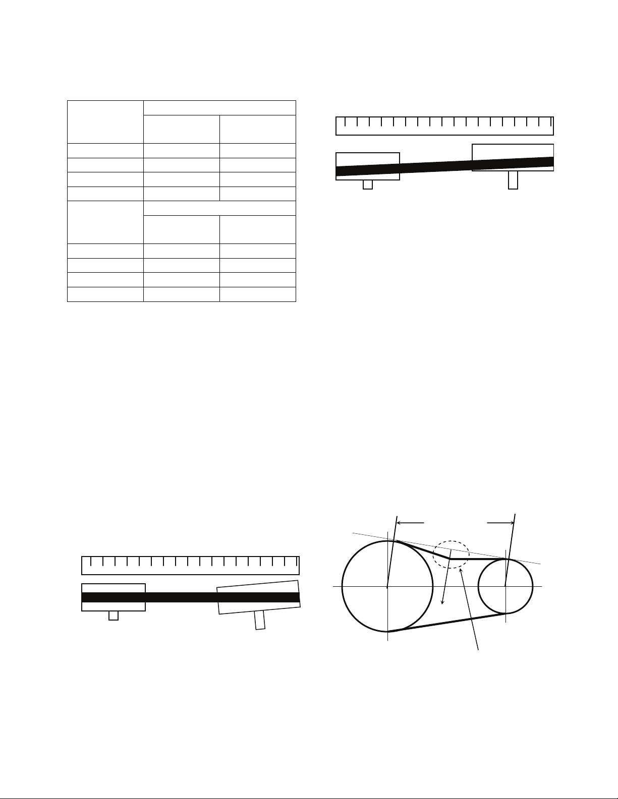
Table 15 - Bearing Setscrew Torque
Recommendations
Shaft Size
(inches)
Setscrew Locking
Thread
Torque
(in-lbs.)
1 1/4 - 28 66 - 85
1 3/16 1/4 - 28 66 - 85
1 7/16 5/16 - 24 126 - 164
1 7/8 3/8 - 24 228 - 296
Shaft Size
(inch)
Skewzloc Locking
Thread
Torque
(in-lbs.)
1 8 - 32 63 - 70
1 3/16 8 - 32 63 - 70
1 7/16 10 - 24 81 - 90
1 7/8 1/4 - 20 162 - 180
Belts
Belt drive misalignment is one of the most
common causes of premature belt failure. A
belt can be destroyed in a matter of days if
the drives have been aligned incorrectly.
The most common tool for measuring
misalignment is a straightedge. Hold the
straightedge flush across one pulley to gauge
the degree of misalignment of the two
sheaves. The maximum allowed
misalignment is one half degree of angular
misalignment, and 1/10th of an inch per foot
between sheave centers for parallel
misalignment.
Pulley Pulley
Straightedge
Belt
Figure 28 - Angular Misalignment
Correct by moving the position of the motor.
Pulley
Straightedge
Pulley
Belt
Figure 29 - Parallel Misalignment
Correct by adjusting sheaves on one, or both
shafts.
Frequent belt tensioning is highly
recommended. Most belt manufacturers
would suggest a re-tensioning after as little
as 8 hours of operation. A simplified
method of adjusting tension is to gauge the
amount of force required to deflect the belt
by 1/64th of an inch per inch of distance
between sheave centers. For example, if the
sheaves are 20 inches apart, then the amount
of deflection with the forces listed below is
20/64th (5/16th) of an inch.
Deflection required for
“A” belts: 4-6 lbs.
“B” belts: 6-10 lbs.
“C” belts: 10-18 lbs.
Sheave Centers
Force
Deflection = 1/64th in.
per inch of length
Figure 30 - Belt Deflection
75
Page 76

Indoor Coils
CAUTIO
Indoor cooling/evaporator coils must be
cleaned regularly to maintain unit efficiency
and operation. Dirty evaporator coils will
eventually freeze up and often result in a
time consuming and expensive service call.
Clean filters will help to prevent dirt from
accumulating on cooling coils, however
cooling coils should be cleaned at least
annually by an HVAC professional.
Refrigeration Cycle
Satisfactory performance of the refrigeration
cycle can be determined by measuring
suction line superheat. In order to determine
if refrigerant flowing from the evaporator is
dry, ensure that the system has enough
refrigerant to produce liquid line subcooling,
but not so much to cause abnormally high
condensing temperatures (and pressures).
Refrigerant cycle analysis is best performed
in conditions that approach the conditions
where the air conditioner will be expected to
operate.
E-Coated Coil Cleaning
Documented routine cleaning of e-coated
coils is required to maintain coating
warranty coverage.
Electric shock hazard. Shut off all
electrical power to the unit to avoid
shock hazard or injury from rotating
parts.
Surface loaded fibers or dirt should be
removed prior to water rinse to prevent
restriction of airflow. If unable to back wash
the side of the coil opposite of the coils
entering air side, then surface loaded fibers
or dirt should be removed with a vacuum
cleaner. If a vacuum cleaner is not available,
a soft non-metallic bristle brush may be
used. In either case, the tool should be
applied in the direction of the fins. Coil
surfaces can be easily damaged (fin edges
bent over) if the tool is applied across the
fins.
Use of a water stream, such as a garden
hose, against a surface loaded coil will drive
the fibers and dirt into the coil. This will
make cleaning efforts more difficult. Surface
loaded fibers must be completely removed
prior to using low velocity clean water rinse.
A monthly clean water rinse is
recommended for coils that are applied in
coastal or industrial environments to help to
remove chlorides, dirt, and debris. It is very
important when rinsing, that water
temperature is less than 130°F and pressure
is than 900 psig to avoid damaging the fin
edges. An elevated water temperature (not to
exceed 130°F) will reduce surface tension,
increasing the ability to remove chlorides
and dirt.
High velocity water from a pressure
washer or compressed air should
only be used at a very low pressure
to prevent fin and/or coil damages.
The force of the water or air jet may
bend the fin edges and increase
airside pressure drop. Reduced unit
performance or nuisance unit
shutdowns may occur.
Quarterly cleaning is essential to extend
the life of an e-coated coil and is required
to maintain coating warranty coverage.
Coil cleaning shall be part of the unit’s
regularly scheduled maintenance
procedures. Failure to clean an e-coated coil
will void the warranty and may result in
reduced efficiency and durability.
N
76
Page 77
CAUTIO
Harsh chemicals, household bleach,
or acid cleaners should not be used
to clean outdoor or indoor e-coated
coils. These cleaners can be very
difficult to rinse out of the coil and
can accelerate corrosion and attack
the e-coating. If there is dirt below the
surface of the coil, use the
recommended coil cleaners.
For routine quarterly cleaning, first clean the
coil with the below approved coil
cleaner. After cleaning the coils with the
approved cleaning agent, use the approved
chloride remover to remove soluble salts and
revitalize the unit.
Recommended Coil Cleaner
The following cleaning agent, assuming it is
used in accordance with the manufacturer’s
directions on the container for proper mixing
and cleaning, has been approved for use on
e-coated coils to remove mold, mildew,
dust, soot, greasy residue, lint and other
particulate:
Enviro-Coil Concentrate, Part Number HEC01.
Recommended Chloride Remover
CHLOR*RID DTS™ should be used to
remove soluble salts from the e-coated coil,
but the directions must be followed closely.
This product is not intended for use as a
degreaser. Any grease or oil film should first
be removed with the approved cleaning
agent.
Remove Barrier - Soluble salts adhere
themselves to the substrate. For the effective
use of this product, the product must be able
to come in contact with the salts. These salts
may be beneath any soils, grease or dirt;
N
therefore, these barriers must be removed
prior to application of this product. As in all
surface preparation, the best work yields the
best results.
Apply CHLOR*RID DTS - Apply directly
onto the substrate. Sufficient product must
be applied uniformly across the substrate to
thoroughly wet out surface, with no areas
missed. This may be accomplished by use of
a pump-up sprayer or conventional spray
gun. The method does not matter, as long as
the entire area to be cleaned is wetted. After
the substrate has been thoroughly wetted,
the salts will be soluble and is now only
necessary to rinse them off.
Rinse - It is highly recommended that a hose
be used, as a pressure washer will damage
the fins. The water to be used for the rinse is
recommended to be of potable quality,
though a lesser quality of water may be used
if a small amount of CHLOR*RID DTS is
added. Check with CHLOR*RID
International, Inc. for recommendations on
lesser quality rinse water.
Energy Recovery Wheel
The AAONAIRE® Energy Recovery Wheel
is a total energy recovery wheel and is a disc
composed of spirally wound desiccant
matrix material. The wheel is divided across
the center when installed, and rotated by an
electric motor at up to 60 rpm so that one
half of the matrix material is exposed at one
moment to the exhaust air stream, and at the
next moment to the ventilation supply air
stream. With a heat wheel, efficiencies of
70 to 85% are achievable for both sensible
and latent energy transfer.
The figure below shows the basics of an
energy recovery wheel.
77
Page 78
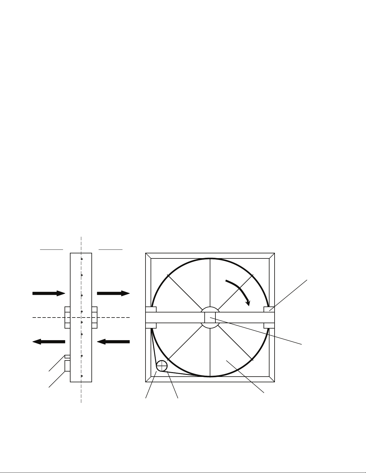
Cleaning
The need for cleaning of the wheel will be
determined by the operating schedule,
climate and regular contaminants of the
conditioned space. The AAONAIRE
Wheel is “self-cleaning” in that the smallest
particles will pass through and larger
particles will land on the wheel surface and
will then be blown clear as the wheel rotates
into the opposite direction of laminar flow.
The primary cleaning need will be to
remove oil based aerosols that have
condensed on energy transfer surfaces.
These oily films can clog micron sized pores
in the desiccant material reducing the
wheel’s efficiency. It can take several years
in a reasonably clean environment such as a
school or an office building, for measurable
efficiency loss to occur. Dirtier air, such as
that from a kitchen, industrial or machine
shop or a smoke filled room, will reduce
efficiency in a much shorter period of time.
Motor Side Pulley Side
Outdoor Air Fresh Air Supply
Indoor Air Exhaust Air
Capacitor
P.C.S. Motor
Pulley Drive Belts
Figure 31 - Energy Recovery Wheel
®
Heat
To clean the wheel, remove the segments
from the wheel frame, and brush foreign
material from the face. Soak the segments in
a non-acid based coil cleaner, or another
alkaline detergent, and warm water.
Massaging the matrix with your hands will
increase the cleaning action. Rinse well, and
shake excess water away before reinstalling.
For applications where frequent cleaning is
required, it is advisable to keep a second set
of wheel segments on hand. While a set is
soaking, or being cleaned, the spare set can
be replaced in the wheel.
“Pulley Side” View
Rim Diameter Seal
Rotation
Bearing Access Cover
Energy Recovery
Wheel with 8
Removable Segments
78
Page 79
Electric Heating
Set thermostat in the heat mode; call for heat
to engage all electric heat strips. Check
blower for proper rotation and voltage.
Measure the amperage and voltage.
Compare them to the nameplate data.
If applicable, check remote heat pump
condenser as per the manufacturer’s
recommendations.
Steam or Hot Water Heating
Set thermostat in the heat mode. Observe
supply blower for proper rotation and
voltage. Check boiler or hot water operation
according to the manufacturer’s instructions.
Check control flow valves for correct
operation and settings per the
manufacturer’s instructions.
Cleaning
Inspect and clean unit interior at the
beginning of each heating and cooling
season and as operating conditions require.
Chilled Water
Check remote chiller operations as per the
manufacturer’s instructions. Check coolant
flow valves for correct operation and
settings.
Lubrication
Most motors and bearings are permanently
lubricated. Some applications may require
that bearings be re-lubricated periodically.
The schedule will depend on the operating
duty, temperature variations, and other
atmospheric conditions.
For bearings equipped with lubrication
fittings, the lubrication schedule is
dependent on operating temperatures and
rotational speeds as shown in the table
below. Lithium based grease conforming to
an NLGI grade No. 2 consistency is
recommended. This medium viscosity, low
torque grease is rust inhibiting and waterresistant. It is satisfactory for operating
temperatures in the range of –10°F to 250°F.
Bearings should only be re-lubricated when
at normal operating temperatures and not
running. Rotate the fan shaft by hand,
adding only enough grease to purge the
seals. A one-inch bearing has a total grease
capacity of only .25 ounces. Added grease
should be limited to .09 ounces.
Do Not Over Lubricate!
Recommended greases are:
SHELL OIL - DOLIUM R
CHEVRON OIL - SRI No. 2
TEXACO INC. - PREMIUM RB
Table 16 - Fan Bearing Lubrication
Schedule
Fan
Speed
500
rpm
1000
rpm
1500
rpm
Any
Speed
Any
Speed
In the event the unit is not functioning
correctly and a service company is required,
only a company with service technicians
qualified and experienced in both
commercial heating and air conditioning
should be permitted to service the systems in
order to keep warranties in effect. The
service tech may call the factory if
assistance is required.
Temp. Environ.
Up to
150 °F
Up to
210 °F
Up to
210 °F
Up to
150 °F
210 -
250 °F
Clean
Clean
Clean Monthly
Dirty
Dirty Weekly
Greasing
Interval
2 to 6
months
2 weeks to
2 months
1 week to
1 month
79
Page 80

Replacement Parts
Parts for AAON equipment may be obtained
from AAON at www.aaonparts.com. When
ordering parts, reference the unit serial
number and part number.
AAON-Longview Customer Service
Department
203 Gum Springs Road
Longview, TX 75602
Ph: 903-236-4403
Fax: 903-236-4463
www.aaon.com
Note: Before calling, technician should have
model and serial number of the unit
available for the service department to help
answer questions regarding the unit.
Filter Replacement
Monthly air filter inspection is required to
maintain optimum unit efficiency. It is
Table 17 - M2-005 and M2-008 Filters
Filter Type
2” Pleated - 30% Eff, MERV 8
4” Pleated - 30% Eff (MERV 8), 65% Eff
(MERV 11), 85% Eff (MERV 13),
or 95% Eff (MERV 14)
12” Cartridge - 65% Eff (MERV 11),
85% Eff (MERV 13),
or 95% Eff (MERV 14)
Table 18 - M2-011 and M2-014 Filters
Filter Type
2” Pleated - 30% Eff, MERV 8
4” Pleated - 30% Eff (MERV 8), 65% Eff
(MERV 11), 85% Eff (MERV 13),
or 95% Eff (MERV 14)
12” Cartridge - 65% Eff (MERV 11),
85% Eff (MERV 13),
or 95% Eff (MERV 14)
strongly recommended that filter media be
replaced monthly. Open access panel and
pull filters straight out to inspect all of the
filters. Replace filters with the size indicated
on each filter. Arrow on the replacement
filters must point towards the blower.
Electric shock hazard. Shut off all
electrical power to the unit to avoid
shock hazard or injury from rotating
parts.
(Quantity) Size
M2-005 M2-008
(2) 20” x 20” (4) 16” x 20”
(Quantity) Size
M2-011 M2-014
(2) 16” x 20” and
(4) 20” x 20”
80
Page 81
Table 19 - M2-018 and M2-022 Filters
Filter Type
2” Pleated - 30% Eff, MERV 8
4” Pleated - 30% Eff (MERV 8), 65% Eff
(MERV 11), 85% Eff (MERV 13),
or 95% Eff (MERV 14)
12” Cartridge - 65% Eff (MERV 11),
85% Eff (MERV 13),
or 95% Eff (MERV 14)
Table 20 - M2-026 Filters
Filter Type
2” Pleated - 30% Eff, MERV 8
4” Pleated - 30% Eff (MERV 8), 65% Eff
(MERV 11), 85% Eff (MERV 13),
or 95% Eff (MERV 14)
12” Cartridge - 65% Eff (MERV 11),
85% Eff (MERV 13),
or 95% Eff (MERV 14)
Table 21 - M2-032 and M2-036 Filters
Filter Type
2” Pleated - 30% Eff, MERV 8
4” Pleated - 30% Eff (MERV 8), 65% Eff
(MERV 11), 85% Eff (MERV 13),
or 95% Eff (MERV 14)
12” Cartridge - 65% Eff (MERV 11),
85% Eff (MERV 13),
or 95% Eff (MERV 14)
(Quantity) Size
M2-018 M2-022
(8) 20” x 20”
(Quantity) Size
M2-026
(4) 16” x 20”
(8) 20” x 20”
(Quantity) Size
M2-032 M2-036
(6) 16” x 20” and
(9) 20” x 20”
(8) 16” x 20” and
(12) 20” x 20”
81
Page 82

Appendix A - Heat Exchanger Corrosion Resistance
Corrosion Resistance of Copper and Stainless Steel in Brazed Plate Heat Exchangers
- Points to Measure and Check in a Water Analysis
The resistance guide provides the corrosion resistance of stainless steel type AISI 316 and pure
Copper (99.9%) in water, to a number of important chemical factors. The actual corrosion is a
very complex process influenced by many different factors in combination.
Explanations: + Good resistance under normal conditions
0 Corrosion problems may occur especially when more factors are valued 0
- Use is not recommended
Water
Containing
Alkalinity
-
/ SO
3
-
)
3
2-
)
4
2-
4
(HCO
Sulfate (SO
HCO
Electrical
Conductivity
pH
Ammonium
+
(NH
)
4
Chlorides (Cl-)*
Free Chlorine
(Cl2)
Hydrogen
Sulfide (H2S)
Free (aggressive)
Carbon Dioxide
(CO
2)
*See Chloride Content Table
Concentration
(mg/l or ppm)
< 70
70-300 + + + +
Time Limits -
Analyze Before
Within 24 Hours
AISI
316
SMO
254
Copper
Alloy
Nickel
Alloy
+ + 0 +
> 300 + + 0/+ +
< 70
70-300 + + 0/- +
No Limit
+ + + +
> 300 0 0 - +
> 1.0
< 1.0 + + 0/- +
No Limit
< 10µS/cm
10-500 µS/cm + + + +
No Limit
+ + + +
+ + 0 +
> 500 µS/cm + + 0 +
< 6.0
6.0-7.5 0/+ + 0 +
7.5-9.0 + + + +
Within 24 Hours
0 0 0 +
> 9.0 + + 0 +
< 2
2-20 + + 0 +
Within 24 Hours
+ + + +
> 20 + + - +
< 300
> 300 0 + 0/+ +
No Limit
< 1
1-5 + + 0 +
Within 5 Hours
+ + + +
+ + + +
> 5 0/+ + 0/- +
< 0.05
> 0.05 + + 0/- +
No Limit
< 5
5-20 + + 0 +
No Limit
+ + + +
+ + + +
> 20 + + - +
82
Page 83

Water
Containing
Total Hardness
(°dH)
Nitrate (NO3)
Iron (Fe)
Aluminum (Al)
Manganese (Mn)
Chloride Content
= 10 ppm SS 304 SS 304 SS 304 SS 316
= 25 ppm SS 304 SS 304 SS 316 SS 316
= 50 ppm SS 304 SS 316 SS 316 Ti / SMO 254
= 80 ppm SS 316 SS 316 SS 316 Ti / SMO 254
= 150 ppm SS 316 SS 316 Ti / SMO 254 Ti / SMO 254
= 300 ppm SS 316 Ti / SMO 254 Ti / SMO 254 Ti / SMO 254
> 300 ppm Ti / SMO 254 Ti / SMO 254 Ti / SMO 254 Ti / SMO 254
Concentration
(mg/l or ppm)
4.0-8.5 No Limit + + + +
< 100
> 100 + + 0 +
< 0.2
> 0.2 + + 0 +
< 0.2
> 0.2 + + 0 +
< 0.1
> 0.1 + + 0 +
60°C (140°F) 80°C (176°F) 120°C (248°F) 130°C (266°F)
Time Limits -
Analyze Before
No Limit
No Limit
No Limit
No Limit
Chloride Content
Maximum Temperature
AISI
316
+ + + +
+ + + +
+ + + +
+ + + +
SMO
254
Copper
Alloy
Nickel
Alloy
83
Page 84

Refrigerant Piping Diagrams
Figure 32 - Standard Split System Piping
84
Page 85

Figure 33 - Modulating Hot Gas Reheat with Hot Gas Bypass Split System Piping
Note: When installing hog gas bypass risers, an oil drip line must be provided at the lowest point
in the system (See Detail A).
85
Page 86

Figure 34 - Hot Gas Bypass Split System Piping
Note: When installing hog gas bypass risers, an oil drip line must be provided at the lowest point
in the system (See Detail A).
86
Page 87

Figure 35 - Modulating Hot Gas Reheat Split System Piping
87
Page 88

88
Figure 36 - Heat Pump Split System Piping
Page 89

Figure 37 - Heat Pump with Factory Installed Modulating Hot Gas Reheat Split System Piping
Note: When installing hog gas bypass risers, an oil drip line must be provided at the lowest point
in the system (See Detail A).
89
Page 90
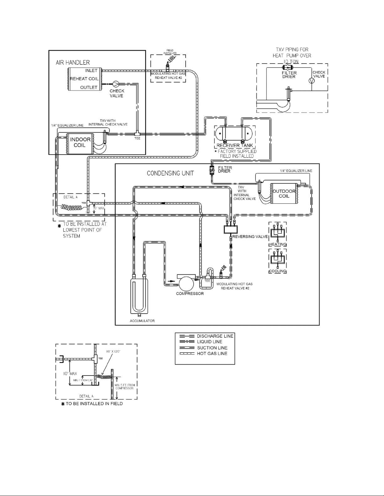
Figure 38 - Heat Pump with Field Installed Modulating Hot Gas Reheat Split System Piping
Note: When installing hog gas bypass risers, an oil drip line must be provided at the lowest point
in the system (See Detail A).
90
Page 91

M2 Series Startup Form
Job Name:_______________________________________________
Date:______________
Address:______________________________________________________________________
______________________________________________________________________________
Model Number:_________________________________________________________________
Serial Number:_____________________________________________ Tag:_______________
Startup Contractor:______________________________________________________________
Address:______________________________________________________________________
_______________________________________________________ Phone:______________
Pre Startup Checklist
Installing contractor should verify the following items.
1. Is there any visible shipping damage? Yes No
2. Is the unit level? Yes No
3. Are the unit clearances adequate for service and operation? Yes No
4. Do all access doors open freely and are the handles operational? Yes No
5. Have all shipping braces been removed? Yes No
6. Have all electrical connections been tested for tightness? Yes No
7. Does the electrical service correspond to the unit nameplate? Yes No
8. On 208/230V units, has transformer tap been checked? Yes No
9. Has overcurrent protection been installed to match the unit nameplate
requirement? Yes No
10. Have all set screws on the fans been tightened? Yes No
11. Do all fans rotate freely? Yes No
12. Does the field water piping to the unit appear to be correct per design
parameters? Yes No
13. Is all copper tubing isolated so that it does not rub? Yes No
14. Have the damper assemblies been inspected? Yes No
15. Are air filters installed with proper orientation? Yes No
16. Have condensate drain and p-trap been connected? Yes No
Ambient Temperature
Ambient Dry Bulb Temperature ________°F
Ambient Wet Bulb Temperature ________°F
91
Page 92

Supply Fan Assembly
Alignment
Check Rotation
Nameplate Amps________
Number hp L1 L2 L3
1
2
Band Size_____________________
VAV Controls_________________
VFD Frequency________________ Springs Operating Correctly
Energy Recovery Wheel Assembly
Wheels Spin Freely
Check Rotation
FLA ________
Number hp L1 L2 L3
1
2
Power Exhaust Fan Assembly
Alignment
Check Rotation
Nameplate Amps________
Number hp L1 L2 L3
1
2
Band Size_____________________
VFD Frequency________________ Springs Operating Correctly
Power Return Fan Assembly
Alignment
Check Rotation
Nameplate Amps________
Number hp L1 L2 L3
1
2
Band Size_____________________
VFD Frequency________________ Springs Operating Correctly
92
Page 93
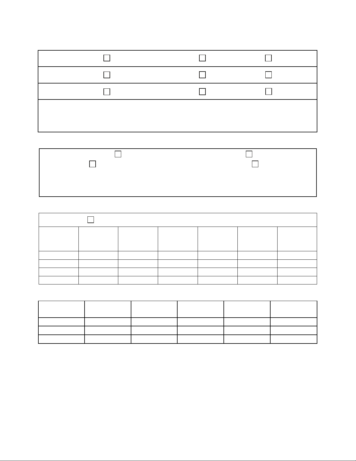
Outside Air/Economizer Dampers
OA Operation Check
RA Operation Check
EA Operation Check
Damper Actuator Type:__________________________________________________________
Economizer Changeover Type and Operation:_______________________________________
Damper Wiring Check
Damper Wiring Check
Damper Wiring Check
Gears Check
Gears Check
Gears Check
Unit Configuration
Water-Cooled Condenser Air-Cooled Condenser
No Water Leaks Condenser Safety Check
Water Flow ________ gpm
Water Inlet Temperature ________°F
Water Outlet Temperature ________°F
Compressors/DX Cooling
Check Rotation
Number L1 L2 L3
Pressure
Head
PSIG
Suction
Pressure
PSIG
Crankcase
Heater
Amps
1
2
3
4
Refrigeration System 1 - Cooling Mode
Pressure
Saturated
Temperature
Line
Temperature
Sub-cooling Superheat
Discharge N/A N/A
Suction N/A
Liquid N/A
93
Page 94
Refrigeration System 2 - Cooling Mode
Discharge N/A N/A
Suction N/A
Liquid N/A
Refrigeration System 3 - Cooling Mode
Discharge N/A N/A
Suction N/A
Liquid N/A
Refrigeration System 4 - Cooling Mode
Discharge N/A N/A
Suction N/A
Liquid N/A
Refrigeration System 1 - Heating Mode (Heat Pump Only)
Discharge N/A N/A
Suction N/A
Liquid N/A
Refrigeration System 2 - Heating Mode (Heat Pump Only)
Discharge N/A N/A
Suction N/A
Liquid N/A
Refrigeration System 3 - Heating Mode (Heat Pump Only)
Discharge N/A N/A
Suction N/A
Liquid N/A
Pressure
Pressure
Pressure
Pressure
Pressure
Pressure
Saturated
Temperature
Saturated
Temperature
Saturated
Temperature
Saturated
Temperature
Saturated
Temperature
Saturated
Temperature
Line
Temperature
Line
Temperature
Line
Temperature
Line
Temperature
Line
Temperature
Line
Temperature
Sub-cooling Superheat
Sub-cooling Superheat
Sub-cooling Superheat
Sub-cooling Superheat
Sub-cooling Superheat
Sub-cooling Superheat
94
Page 95

Refrigeration System 4 - Heating Mode (Heat Pump Only)
Pressure
Saturated
Temperature
Line
Temperature
Sub-cooling Superheat
Discharge N/A N/A
Suction N/A
Liquid N/A
Air-Cooled Condenser
Alignment
Check Rotation
Nameplate Amps________
Number hp L1 L2 L3
1
2
3
4
5
6
Water/Glycol System
1. Has the entire system been flushed and pressure checked? Yes No
2. Has the entire system been filled with fluid? Yes No
3. Has air been bled from the heat exchangers and piping? Yes No
4. Is the glycol the proper type and concentration (N/A if water)? Yes No
5. Is there a minimum load of 50% of the design load? Yes No
6. Has the water piping been insulated? Yes No
7. What is the freeze point of the glycol (N/A if water)? ______________________________
Gas Heating
Natural Gas Propane Purge Air from Lines Verify Pilot Spark
Stage Manifold Pressure (w.c.) Stage Manifold Pressure (w.c.)
1 3
2 4
95
Page 96

Electric Heating
Stages__________ Limit Lockout Aux. Limit Lockout
Stage Amps Stage Amps
1 5
2 6
3 7
4 8
96
Page 97

Maintenance Log
This log must be kept with the unit. It is the responsibility of the owner and/or
maintenance/service contractor to document any service, repair or adjustments. AAON Service
and Warranty Departments are available to advise and provide phone help for proper operation
and replacement parts. The responsibility for proper startup, maintenance and servicing of the
equipment falls to the owner and qualified licensed technician.
Entry Date Action Taken Name/Tel.
97
Page 98

Literature Change History
March 2010
Update of IOM adding gas heater, self contained unit and packaged rooftop unit information.
July 2010
Update of IOM adding PVC and CPVC piping Caution and split system piping information.
November 2010
Update of IOM adding control wiring information, correcting M2-022 and M2-026 filter sizes
and adding modulating hot gas reheat only piping diagram.
June 2011
Update of the IOM adding additional electric heat capacity options to the heat module, correcting
the condensate drain connection to 1” MPT, and adding the electronic startup form.
April 2012
Update of the IOM, changing the suction trap requirement for variable capacity scroll
compressor circuits to every 10 feet, correcting the Modulating Hot Gas Reheat and Modulating
Hot Gas Reheat with Hot Gas Bypass piping diagrams to show the liquid line tee connection factory
installed, adding the Heat Pump with Field Installed Modulating Hot Gas Reheat Split System Piping
Diagram,
and updating the table of contents.
98
Page 99

Page 100

AAON
2425 South Yukon Ave.
Tulsa, OK 74107-2728
Phone: 918-583-2266
Fax: 918-583-6094
www.aaon.com
M2 Series
Installation, Operation &
Maintenance
R40681 · Rev. B · 120509
(ACP 30752)
It is the intent of AAON to provide accurate and current product information. However, in the
interest of product improvement, AAON reserves the right to change pricing, specifications,
and/or design of its product without notice, obligation, or liability.
Copyright © AAON, all rights reserved throughout the world.
AAON® and AAONAIRE® are registered trademarks of AAON, Inc., Tulsa, OK.
 Loading...