

Page 1

A
Modular Air Handlers
Celebrity1
TM
Installation and
Operation Manual
October 2004
AON
®
Think Ahead.
Page 2

Since the inception of AAON® in 1988, we have maintained our commitment to design, develop,
manufacture, and deliver heating and cooling products to perform beyond all expectations and to
demonstrate their daily value to our customers.
AAON utilizes extensive product knowledge and state of the art manufacturing to continuously
provide practical HVAC products to the dynamic marketplace.
Our objective remains the same:
Meet the customer specific requirement
at a reasonable first cost.
AAON’s Celebrity1TM Modular Air Handler gives you near limitless capability for conquering
complex projects. Its superior modular design can be as flexible as your application is
demanding. Units can be ordered completely factory wired and assembled, ready for placement
and start-up, or as separate modules, to be manipulated and connected on site. With multiple
factory-installed conservation, air, and control options to choose from, AAON’s modular systems
fit jobs that would normally require a custom system design with intensive post-installation work.
That makes the Celebrity1TM very cost-effective, while creating happier customers for you.
Construction Process Based Design
− Double Wall Insulated Module
− G90 Galvanized Steel
− Maximum Access Doors/Panels
− Stainless Steel Hinges
− Cast Door Handles
− Double Sloped Drain Pan
− Field Ready Duct Flanges
Standard Features
− Multiple Coil Configurations
− External Coil Connection Stubs
− Lift-off Hinged Doors
− Factory Installed TXV on All DX Coils
Other Factory Installed Options
− Hot Gas Reheat
− Hot Gas Bypass
− Face and Bypass Applications
− AAONAIRE
− Left or Right Hand Connections
− Numerous Humidity Control Solutions
− Stainless Steel Drain Pan
®
Heat Wheel
− Horizontal – Vertical Applications
− Panels/Doors Interchangeable
− All Sections Full Perimeter Gasket Sealed
− Multiple Wiring Combinations
− Single or Dual Path Configurable
− Multiple Energy Recovery
Arrangements
− Control Circuit Transformer
− Fan Contactors
− Left or Right Side Access
− Adjustable Belt Drive and Motor Mount
− Oversized and High Efficiency Motors
− Custom Coil Designs
− Factory or Customer Supplied Controls
− Customizable “Blank” Modules
− Power Exhaust Selections
− Multiple Filtration Choices
− Various Safety Devices
2
Page 3

Owner should pay particular attention to the
p
words: NOTE, CAUTION, and WARNING.
Celebrity1 Modular Air Handler
Installation and Operation Manual
October 2004
NOTES are intended to clarify or make the
installation easier. CAUTIONS are given to
prevent equipment damage. WARNINGS are
given to alert owner that personal injury and/or
equipment damage may result if installation
rocedure is not handled properly.
1. Description ……………………….. 4
Important Safety Information
Unit Data
Unit Orientation
2. Model Number Nomenclature .… 6
Number Structure
Base Model Number
Individual Module Numbers
3. Delivery ……………………………. 13
Receipt & Inspection
Storage
4. Installation ………………………… 14
General
Certification
Codes & Ordinances
Handling
Service & Installation Clearance
Mounting & Suspension
Field Assembly
Sealing
Cooling Equipment
Heating Equipment
Condensate Piping
Electrical
Thermostat
Filters
5. Refrigerant Piping &
Line Sizing Information ….……... 20
General
Liquid Line Piping
Suction Line Piping
Other Piping
6. Start-Up ……………………… 24
General
Procedures
Air Balancing
Water Balancing
Controls
7. Operation & Maintenance … 26
General
Maintenance Schedule
Blower Assembly
Coils
Refrigeration Cycle
Charging
Heating
Cleaning
Chilled Water
Lubrication
Service
Filters
8. Hot Gas Bypass (HGBP) ….. 31
9. Hot Gas Reheat (HGRH) ….. 32
10. HGBP & HGRH Together 33
11.
AAONAIRE® Heat Wheel …..
Cleaning
12. Troubleshooting …………… 36
Common Problems
Compressor Check-Out
13. Factory Start-Up Form ……. 39
WARNING WARNING
The information in this manual should be followed
exactly to prevent property damage or personal
injury.
Installation and service must be performed by a
qualified installer or service agency.
34
3
Page 4

r
–
y
f
r
f
r
t
–
r
t
r
r
1. Description
Important Safety Information
ONLY QUALIFIED PERSONNEL SHOULD
PERFORM INSTALLATION, OPERATION, AND
MAINTENANCE OF EQUIPMENT DESCRIBED IN
THIS MANUAL.
Celebrity1
operation when installed, operated, and maintained
within design specifications, and the instructions
set forth in this manual. It is necessary to follow
these instructions to avoid personal injury o
damage to equipment or property during equipmen
installation, operation, and maintenance.
This equipment is protected by a standard limited
warranty under the condition that initial installation,
service, and maintenance is performed according
to the instructions set forth in this manual. This
manual should be read in its entirety prior to
installation, and before performing any service o
maintenance work.
Equipment described in this manual is available
with many optional accessories. If you have
questions after reading this manual in its entirety,
consult other factory documentation, or contac
your Sales Representative to obtain furthe
information before manipulating this equipment, o
its optional accessories.
RISK OF DAMAGE, INJURY, AND LOSS OF
LIFE - Improper installation, adjustment,
alteration, service or maintenance can cause
property damage, personal injury, or loss o
life. A qualified installer or service agency
must perform installation and service.
TM
air handlers are designed for safe
NOTE
IMPORTANT!
WARNING
WARNING
RISK OF ELECTRICAL SHOCK -
Before attempting to perform any service o
maintenance, turn the electrical power to the
unit OFF at disconnect switch(es). Unit may
have multiple power supplies.
WARNING
RISK OF INJURY FROM HOT PARTS
Disconnect all power before servicing electric
resistance heating elements to prevent serious
injury resulting from automatic starts. Unit ma
have multiple power supplies.
WARNING
RISK OF INJURY FROM HOT PARTS
Disconnect all power, close all isolation valves,
and allow equipment to cool before servicing
equipment with hot water and steam heating coils.
Hot water will circulate even after power is off.
Equipment may have multiple power supplies.
WARNING
RISK OF INJURY FROM MOVING PARTS Disconnect all power before servicing motor o
blower to prevent serious injury resulting from
automatic starts. Motor and blower may have
multiple power supplies.
WARNING
NOTE
These units must not be used as a “construction
heater” at any time during any phase o
construction. Very low return air temperatures,
harmful vapors, and misplacement of the filters will
damage the unit and its efficiency.
4
Page 5
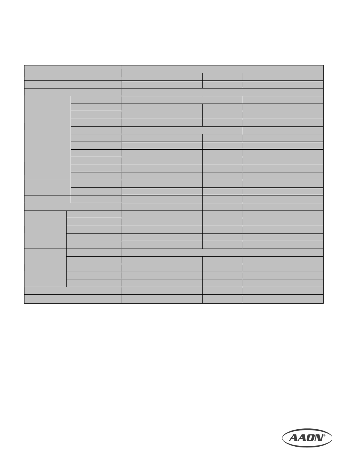
Unit Data
Table 1.1, Unit Data
Features
CFM RANGE
05 08 11 14 18
1,000 to 2,700 2,000 to 4,400 3,100 to 6,000 5,000 to 7,700 6,000 to 10,300
Model Cabinet Size
COOLING COIL SELECTION Face Area Sq. Ft.
DX Single Circuit
4 Row
6 Row
DX Cooling
Chilled Water
Cooling
*Hot Water
Heating
Hot Gas Reheat
8 Row
DX Double Circuit
4 Row
6 Row
8 Row
4 Row
6 Row
8 Row
1 Row
2 Row
2 Row
Min. / Max. Electric Heating kW
Quantity
Type
Fan
Filters
Wheel O.D. (In.)
Max. RPM
Motor HP
Type
Pleated 2" Flat
Pleated 4" Flat
12" Cartridge
12" Bag
Max. Total Static Pressure (In. w.g.)
AAONAIRE Heat Wheel O.D.
4.7 7.7 10.5 13.5 18.0
4.7 7.7 10.5 13.5 18.0
4.7 7.7 10.5 13.5 18.0
4.7 7.7 10.5 13.5 18.0
4.7 7.7 10.5 13.5 18.0
4.7 7.7 10.5 13.5 18.0
4.7 8.0 10.2 13.6 18.1
4.7 8.0 10.2 13.6 18.1
4.7 8.0 10.2 13.6 18.1
4.7 8.0 10.2 13.6 18.1
4.7 8.0 10.2 13.6 18.1
4.7 7.7 10.5 13.5 18.0
5.3 / 21.0 10.5 / 42.0 10.5 / 42.0 10.5 / 42.0 10.5 / 70.0
1 1 1 1 1
Back Incline Back Incline Back Incline Back Incline Back Incline
15 15 / 18.5 18.5 / 22.5 18.5 / 22.5 22.5 / 27
2200 2200 / 2200 2200 / 2200 2200 / 2200 2200 / 1800
1, 2, 3 1, 2, 3, 5, 7.5 3, 5, 7.5, 10 3, 5, 7.5, 10 3, 5, 7.5, 10
Size In. (Qty.)
16 x 20 (2) 16 x 20 (4) 16 x 20 (6) 20 x 20 (6) 25 x 20 (6)
16 x 20 (2) 16 x 20 (4) 16 x 20 (6) 20 x 20 (6) 25 x 20 (6)
16 x 20 (2) 16 x 20 (4) 16 x 20 (6) 20 x 20 (6) 18 x 24 (6)
16 x 20 (2) 16 x 20 (4) 16 x 20 (6) 20 x 20 (6) 20 x 24 (6)
3.2 4.5 4.5 4.0 3.5
29" 44" 56" 56" 68"
*Includes Hot Water Preheat & Reheat
5
Page 6
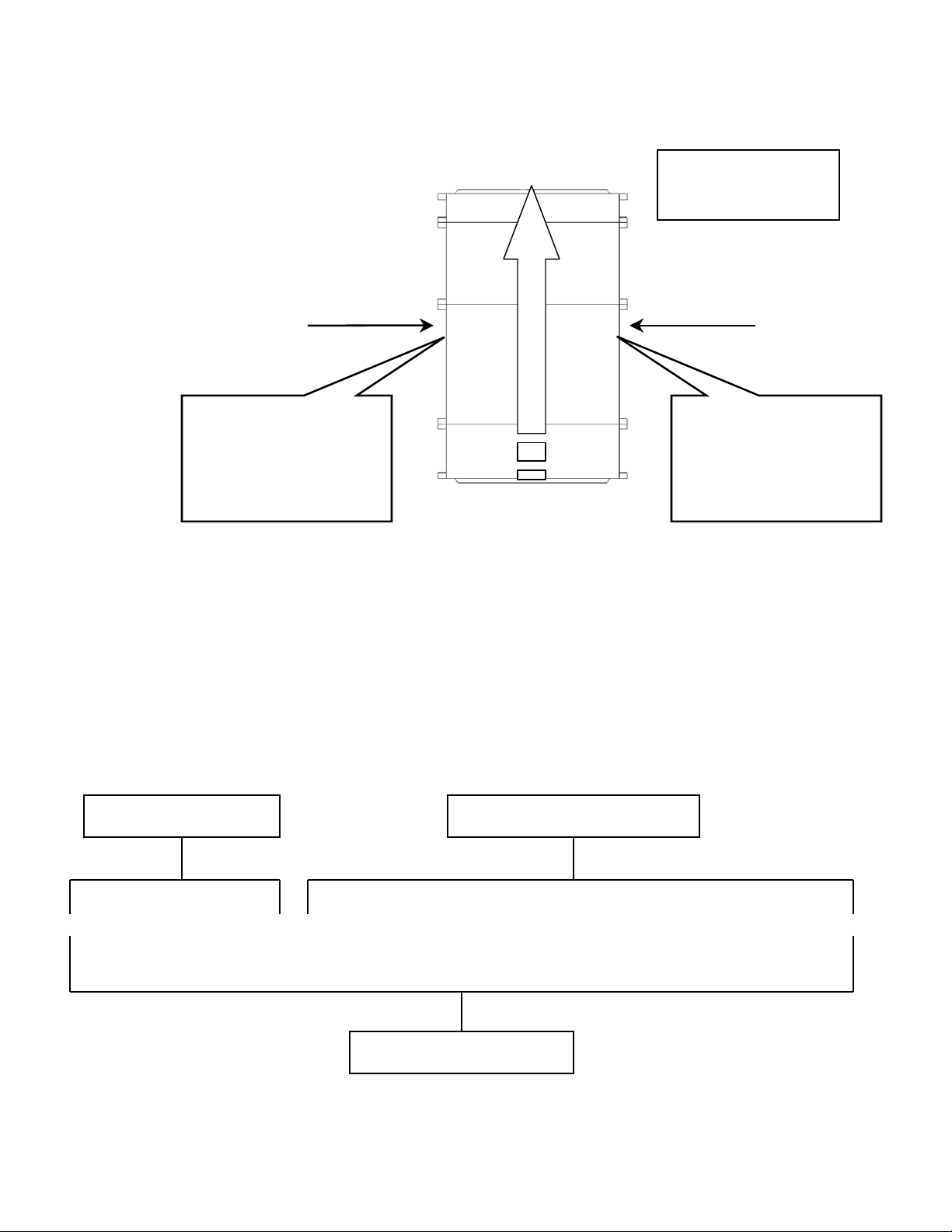
Unit Orientation
A
When determining unit orientation
(or Supply Air Flow as it is
identified in the base model
number below), consider the air to
be “hitting you in the back of the
head” when you are facing the
return air end of the unit.
Figure 1.1, Unit Orientation
Left Hand Side
Supply Air
Top View
Assembled Modular
Air Handler
Right Hand Side
If you have a “Left Hand”
unit, then all connections
will be on the left hand
side of the unit. Air will
flow from right to left as
you look at the left side.
Return Air
If you have a “Right Hand”
unit, then all connections
will be on the right hand
side of the unit. Air will
flow from left to right as
you look at the right side.
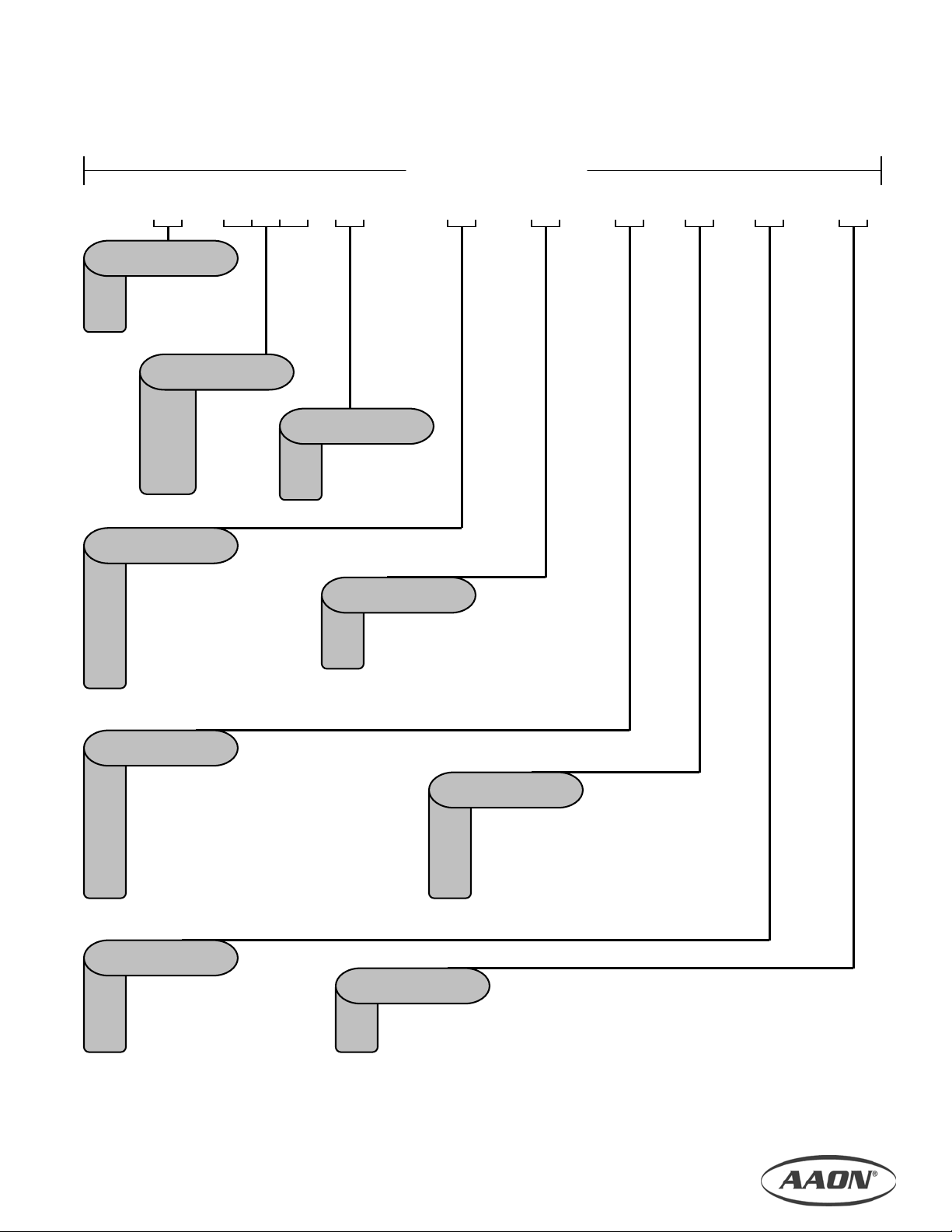
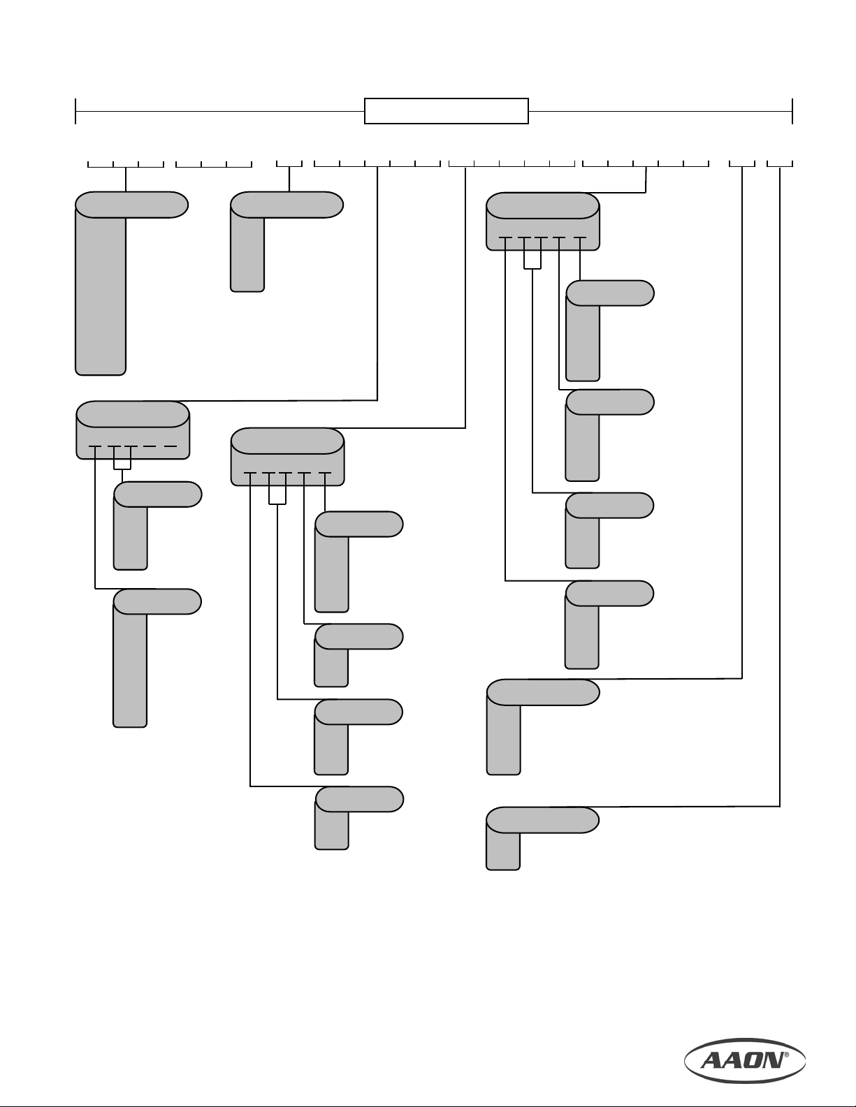
2. Model Number Nomenclature
Number Structure
The total unit model number consists of a base model number followed by individual model numbers. The base
model number identifies main unit features. Individual module numbers identify module configurations and optional
features.
Figure 2.1, Model Number Structure
Base Model Number
Individual Module Numbers
M1-H-018-R-2-B-A-0-A-0
:
MBH-101-A-00-00000-00000-0-0 ~ FTB-102-P-A0-00000-00000-0-0 ~
CLC-103-E-00-00000-610I0-S-X ~ CLA-104-0-00-110H0-00000-0-0 ~
SFC-105-K-D0-
008D-00000-0-X
Total Unit Model Number
6
Page 7
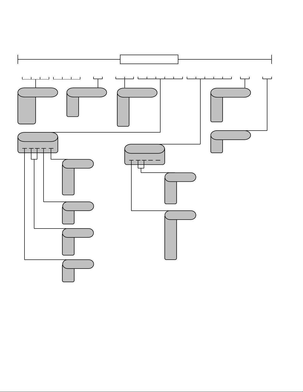
Base Model Number
M1
TYPE
- - - - - - - -
H =
V =
Horizontal
Vertical
SIZE
005 =
008 =
011 =
014 =
018 =
5
8
11
14
18
VOLTAGE
1 =
230V/1Ø/60HZ
2 =
230V/3Ø/60HZ
3 =
460V/3Ø/60HZ
4 =
575V/3Ø/60HZ
8 =
208V/3Ø/60HZ
9 =
208V/1Ø/60HZ
WIRING
No Factory Wiring
0 =
Control Panel in Fan Box
A =
Control Panel in Control Box
B =
Loose Control Panel
C =
Control Panel in Standard NEMA Box
D =
Control Panel in Large NEMA Box
E =
BASE RAIL
4” High
A =
8” High
B =
6” High
C =
MAIN FEATURES
SUPPLY AIR FLOW ASSEMBLY WIRING PAINT BASE RAIL SPECIAL
SUPPLY AIR FLOW
L =
Left Hand
R =
Right Hand
ASSEMBLY
Factory Assembled
A =
Loose Boxes
B =
SPECIAL
None
0 =
=
SPA Req’d.
VOLTAGESIZE TYPE
0 =
A =
B =
C =
PAINT
No Paint
Standard White Exterior
Special Color Exterior
Anti-Corrosion Paint
7
Page 8
Individual Module Numbers
-
-
MODULE ID
PHA =
PHB =
RHC =
PHC =
PHD =
E-Heat
Heat
HGRH
Heat / Filter
E-Heat / Filter
FUNCTION
H =
Heating
D =
Dehumidification
B =
Heating & Dehum.
HEATING COIL
COATING
0 =
Standard
P =
Phenolic Coating
S =
Stainless Steel Casing
H =
Stainless Steel Casing
& Copper Fin
CIRCUITING
Single Serpentine
F =
Half Serpentine
H =
FPI
08 =
10 =
12 =
ROWS
1 =
2 =
8 Fins Per Inch
10 Fins Per Inch
12 Fins Per Inch
1 Row
2 Rows
HEAT MODULE
FUNCTION HEATING COIL TYPE
FILTERSPOSITION MODULE ID ELECTRIC HEAT
-
C0 =
D0 =
E0 =
-
FILTERS
00 =
None
A0 =
2” 30% Std.
B0 =
4” 30% Std.
4” 65% Std.
4” 85% Std.
4” 95% Std.
ELECTRIC HEAT
- -
FILTER OPTIONS
0 =
A =
B =
C =
0 =
X =
FILTER
OPTIONS
0 0
None
Magnehelic Gauge
Clogged Filter Switch
Magnehelic Gauge &
Clogged Filter Switch
TYPE
None
Special (SPA Req’d.)
-
00
STAGES
01 =
1 Stage
02 =
03 =
04 =
A =
B =
C =
D =
H =
E =
F =
G =
2 Stage
3 Stage
4 Stage
KW
7 (5.3)
14 (10.5)
21 (15.8)
28 (21.0)
35 (26.3)
42 (35.0)
56 (42.0)
70 (52.5)
8
Page 9
yp
MODULE ID
CLB =
CLC =
CLD =
CLE =
CLF =
CLG =
CLH =
CLI =
CLJ =
CLK =
CLL =
CW / DX
Cool / HGRH
E-Heat / Heat
E-Heat
Heat & Cool
E-Heat / Cool
E-Heat / Cool / HGRH
Cool or Heat w/Face Bypass
HW / DX / HGRH
Vertical CW or DX
Cool and Heat w/ Face Bypass
ELECTRIC HEAT
STAGES
01 =
02 =
03 =
04 =
A =
B =
C =
D =
H =
E =
F =
G =
POSITION MODULE ID ELECTRIC HEAT
COOLING
-
COOLING TYPE
0 =
No Cooling
C =
CW
D =
DX
E =
DX & Hot Gas
ass
B
0 0
1 Stage
2 Stage
3 Stage
4 Stage
KW
7 (5.3)
14 (10.5)
21 (15.8)
28 (21.0)
35 (26.3)
42 (35.0)
56 (42.0)
70 (52.5)
HEATING COIL
COATING
0 =
P =
S =
H =
CIRCUITING
F =
H =
08 =
10 =
12 =
1 =
2 =
COIL MODULE
Standard
Phenolic Coating
Stainless Steel Casing
Stainless Steel Casing
& Copper Fin
Single Serpentine
Half Serpentine
FPI
8 Fins Per Inch
10 Fins Per Inch
12 Fins Per Inch
ROWS
1 Row
2 Rows
HEATING COIL
- - - -
COOLING COIL
DRAIN PAN
0 =
None
S =
Stainless Steel Pan
G =
Galvanized Pan
U =
Stainless Steel Pan
& UV Light
TYPE
0 =
None
Special (SPA Req’d.)
X =
00
COATING
0 =
P =
S =
H =
CIRCUITING
F =
H =
S =
I =
08 =
10 =
12 =
ROWS
4 =
6 =
8 =
COOLING COIL
Standard
Phenolic Coating
Stainless Steel Casing
Stainless Steel Casing
& Copper Fin
Single Serpentine
Half Serpentine
DX Single Circuit
DX Interlaced (Dual)
FPI
8 Fins Per Inch
10 Fins Per Inch
12 Fins Per Inch
4 Row
6 Row
8 Row
DRAIN
TYPE
PAN
--
9
Page 10

r
r
r
r
- -
FILTER TYPE SAFETY CONTROL TYPE
FILTERSPOSITION MODULE ID
-
MODULE ID
FTA =
FTF =
FTC =
FTD =
Flat Filter, Small
Flat Filter, Large
Cartridge Filter
Bag Filte
FILTER TYPE
P =
C =
B =
Pleated
Cartridge
Bag
PLEATED
A0 =
B0 =
C0 =
D0 =
E0 =
2” 30% Eff. Std.
4” 30% Eff. Std.
4” 65% Eff. Std.
4” 85% Eff. Std.
4” 95% Eff. Std.
CARTRIDGE
C0 =
D0 =
E0 =
- -
ACTUATOR SAFETY CONTROL TYPE
FILTERSPOSITION MODULE ID
-
MODULE ID
MBA =
MBB =
MBC =
MBF =
MBH =
MBD =
MBE =
MBI =
MBJ =
Vertical Damper
Horizontal (Top) Damper
Vertical / Horizontal (Bottom) Damper
Horizontal (Bottom) Damper
Vertical / Horizontal (Top) Dampe
Vertical Damper / Filte
Horizontal (Top) Damper / Filter
Horizontal (Bottom) Damper / Filter
Vertical / Horizontal (Top) Damper / Filte
ACTUATOR
0 =
None
A =
Two Position
=
DDC
*Filters compatible with modules MBD, MBE, MBI, & MBJ only.
FILTER MODULE
- - - -
FILTERS
65% Eff.
85% Eff.
95% Eff.
MIXING MODULE
-
FILTERS*
00 =
None
A0 =
2” 30% Std.
B0 =
4” 30% Std.
C0 =
4” 65% Std.
D0 =
4” 85% Std.
E0 =
4” 95% Std.
SAFETY CONTROL
None
0 =
Smoke Detector
1 =
Firestat
2 =
Smoke Detector
3 =
& Firestat
0000 0 0 0 00
SAFETY CONTROL
None
0 =
Smoke Detector
1 =
Firestat
2 =
Smoke Detector
3 =
& Firestat
BAG
B0 =
45% Eff.
C0 =
65% Eff.
D0 =
85% Eff.
E0 =
95% Eff.
0000 0 0 0 0
BYPASS OPEN
0 =
None
A =
Top Open
B =
Bottom Open
BYPASS OPEN
-
BLANK
FILTER OPTIONS
0 =
A =
B =
C =
0 =
X =
FILTER OPTIONS
0 =
A =
B =
C =
0 =
X =
FILTER
OPTIONS
None
Magnehelic Gauge
Clogged Filter Switch
Magnehelic Gauge &
Clogged Filter Switch
TYPE
None
Special (SPA Req’d.)
FILTER
OPTIONS
- -
None
Magnehelic Gauge
Clogged Filter Switch
Magnehelic Gauge &
Clogged Filter Switch
TYPE
None
Special (SPA Req’d.)
10
Page 11
X
X
X
X
MODULE ID
PEA =
RFA =
SFA =
SFB =
SFC =
PEC =
MOTOR SIZE
0 =
E =
F =
G =
H =
J =
K =
MODULE ID
BBA =
BBB =
BBC =
BBD =
POSITION MODULE ID
Power Exhaust
Return Fan
Supply Fan
Supply Fan, Vertical
Supply Fan, Top Discharge
Exhaust Fan, Top Discharge
None
1 HP
2 HP
3 HP
5 HP
7.5 HP
10 HP
-
Small Blank
Large Blank
Small Blank, Top Discharge
Large Blank, Top Discharge
FAN MODULE
MOTOR
SIZE
BLOWER
-
BLOWER
0 =
None
A =
15”
B =
18.5”
C =
22.5”
D =
27”
MOTOR TYPE
0
- - -
MOTOR TYPE
00
-
SAFETY CONTROL
0 =
A =
SPECIAL CONTROL
0 =
A =
B =
00
TYPE
A =
B =
C =
D =
Standard
Premium
Premium w/ VFD
Premium w/ VFD
& Bypass
PULLEYS
Pulley
Combinations
Assigned At
Factory Acc.
To Order
Requirements
0 =
X =
BLANK MODULE
BLANK SAFETY CONTROL
- -
0
BLANK POSITION MODULE ID BYPASS OPEN
0
SAFETY CONTROL
0 =
1 =
2 =
3 =
- -
0
None
Smoke Detector
Firestat
Smoke Detector
& Firestat
0000 0 0 0 0
BYPASS OPEN
0 =
None
A =
Top Open
B =
Bottom Open
SAFETY
CONTROL
0 0 0 0
None
Phase & Brownout
Protection
None
DDC Control & Terminal
DDC Control
TYPE
None
Special (SPA Req’d.)
DRAIN PAN
0 =
S =
G =
U =
0 =
X =
SPECIAL
CONTROL
--
-
None
Stainless Steel Pan
Galvanized Pan
Stainless Steel Pan
& UV Light
TYPE
None
Special (SPA Req’d.)
DRAIN
PAN
TYPE
TYPE
-
11
Page 12

A
-
AAONAIRE HEAT RECOVERY WHEEL MODULE
WHEEL SIZE BLANK
- -
BLANK POSITION MODULE ID BLANK
- - - -
0
0
MODULE ID
HRA =
AONAIRE Heat Wheel
WHEEL SIZE*
Standard
A =
Optional
B =
*Optional wheel size (selection ‘B’) available only in size 5, 8, and 11 units.
-
BLANK SAFETY OPTIONS
- - - - - -
CONTROL PANEL MODULE
BLANK POSITION MODULE ID BLANK
0
MODULE ID
TRA =
Control Panel
SAFETY CONTROL
0 =
1 =
2 =
3 =
None
Smoke Detector
Firestat
Smoke Detector
& Firestat
BLANK
0000 0 0 0 00
0000 0 0 0 00
00
TYPE
0 =
None
Special (SPA Req’d.)
X =
BLANK
000
TYPE
0 =
None
Special (SPA Req’d.)
X =
TYPE
TYPE
12
Page 13

3. Delivery
t
r
ALL SHIPMENTS ARE F.O.B. THE FACTORY. IT IS
THE RESPONSIBILITY OF THE RECEIVING PARTY
TO INSPECT THE EQUIPMENT UPON ARRIVAL.
Receipt & Inspection
The air handler should be inspected for damage that
may have occurred in transit. Do the following upon
receipt:
1. Inspect all items for internal, external, and
concealed damage before accepting
2. Assure carrier is in compliance with Bill of
If damage is found:
If repairs must be made to damaged goods, the factory
must be notified before any repair action is taken.
Equipment alteration, repair, or unauthorized
manipulation of damaged equipment without the
manufacturer’s consent will void all product warranties.
Contact the ACP Warranty Department for assistance
with handling damaged goods, repairs, and freight
claims.
Verify the equipment against the order documents
upon delivery. If what you received does not match
your order exactly, then your sales representative
must be notified at once.
Lading instructions
1. Note all damage on Bill of Lading immediately
− Photograph damage if possible
− Do not move or discard damaged
packaging materials
2. Call carrier immediately to file a freight claim,
and to schedule a freight inspection
3. When damage is repairable, call ACP’s
Customer Care Hotline for parts: 1-903-2479242
4. With permission of carrier, make the repairs
5. Stay in contact with carrier to ensure payment
of your claim
NOTE
LOOSE SHIPMENT ITEMS – Upon receipt, check
shipment for items that ship loose such as
thermostats, and other controls. Consult order and
shipment documentation to identify potential looseshipped items.
NOTICE OF PILFERING – Check packing lis
against delivered goods. Ensure that equipment,
and loose-shipped items have not been stolen, o
misplaced during staging or transit. The factory is
not responsible for missing items after
NOTE
shipment.
Storage
This equipment is not suitable for outdoor use, or
storage. Never place this equipment where it may be
subjected to outdoor conditions such as rain, snow,
humidity, extreme temperatures, or corrosive
chemicals.
If installation will not occur immediately following
delivery, then store equipment in a dry, protected area,
and in the proper orientation as marked on the
packaging with all internal packaging in place. Secure
all loose-shipped items.
Page 14
4. Installation
t
t
A
General
Celebrity1TM modular air handling units are designed
as heating, cooling, or combination units for indoor
installation only. The use of refrigerant, chilled water,
electric resistance, steam, or hot water as operating
mediums will be dictated by design of the heating and
cooling coils installed in the unit. Flexible connectors
are required on all duct connections and installed to
minimize air leaks.
Certification
Cooling Models
a) Certified for use with a commercial
condensing or chilled water remote unit (with
or without compressor(s))
b) Certified for indoor installation only.
Steam or Hot Water Heat Models
a) Certified for indoor installation only.
Electric Heat Models
a) Certified as an electric warm air furnace with
or without cooling coil.
b) Certified for indoor installation only.
Codes & Ordinances
System should be sized in accordance with National
Warm Air Heating and Air Conditioning Association
Literature, or the Guide of American Society of
Heating, Refrigeration and Air Conditioning Engineers.
The installation must conform with local building
codes, or in the absence of local codes, with (United
States) “ANSI / UL 1995”, (Canada) current, C.S.A.
Standard C22.2, No. 236, Canadian Electrical Code
Part 1, and C.S.A. Standard B52 Mechanical
Refrigeration Code, and Local Plumbing or Waste
Water Codes.
It is the responsibility of the installing contractor to
comply with codes, ordinances, local and
municipal building laws, and manufacturer’s
instructions. Personal injury and/or equipmen
damage may result if proper procedures are no
followed.
WARNING
Handling
Be aware of what is contained in the equipment!
Dependent upon the optional accessories that were
ordered, this equipment may contain fragile
components and delicate electronics. Although the
unit is constructed of sturdy materials, avoid impacts
and handling methods that may damage internal
apparatus and structure, or the exterior surfaces of the
unit. Take care not to apply destructive force to coils,
coil and drain stub-outs, or other parts protruding
beyond the extents of the unit casing. Always handle
the unit by its exterior casing, and never by any of the
protruding parts.
Keep equipment free from debris and construction
waste during installation. Foreign materials may
adversely affect unit operation resulting in premature
failures that will not be covered by the manufacturer’s
warranty. Attach all service panels, and cover all
exposed equipment when work is not being performed.
Leave unit protected from other construction activity
until start-up is to occur.
WARNING
lways wear hand and eye protection when
handling, installing, servicing, or maintaining
equipment. Sharp or pointed edges, moving parts,
and flying debris may cause personal injury.
Service & Installation Clearance
Before setting the air handler into place, caution must
be taken to provide clearance for unit panels/doors
that must be accessible for periodic service. These
areas contain the controls, safety devices, refrigerant
or water piping, shut-off valves and filter access.
Celebrity1
from both sides of the unit. Service clearance equal to
the width of the unit is recommended. That is, if the
unit is 4 feet wide, then 4 feet of clearance is
suggested on both sides.
TM
air handler modules may be accessible
Blower Module
The blower module needs to be accessible with
enough clearance to remove the motor or the plenum
fan.
14
Page 15

Coil & AAONAIRE Heat Wheel Modules
r
l
Coils and heat wheels slide out for easier servicing.
There should be enough clearance left on one side of
the unit (usually the piping connection side) to
completely remove the coils and heat wheel for
maintenance or replacement.
Figure 4.1, Service Clearance for Heat Wheel and Coils
AAONAIRE
Heat Wheel
Module
Coil Module
Coil
X
‘X’ is the minimum
required service
clearance for heat whee
and coil modules
Module
Size
5 48 inches
8 64 inches
11 68 inches
14 68 inches
18 89 inches
X =
Mounting & Suspension
CelebrityTM air handlers can be designed for horizontal
or vertical airflow applications, and can be floor
mounted or suspended. Units may be delivered in
separate module components, or completely factory
assembled with all modules connected. In the latter
case, if the unit was received fully assembled on a
skid, then the equipment should be lifted into place
using the shipping skid to prevent damage to the
modules.
An auxiliary (emergency) drain pan is
recommended for all applications where there is a
risk of water damage to surrounding structure o
furnishings. Refer to local codes.
Floor Mounted
NOTE
Make sure the unit is level, and installed with a
minimum height of 6” to allow for proper drainage of
the condensate line. Other installation provisions may
be necessary according to job specifications.
Suspended
Modular air handlers are equipped for suspended
installations. All modules must be connected and the
unit must be completely assembled before the unit is
lifted into position. The base of the unit must be
supported before hoisting. Do not lift the unit by any
part other than the unit base.
Unit base rails are manufactured with suspension rod
holes. To suspend an assembled unit, insert support
rods through the aligned base rail holes on both sides
of the unit. Secure suspension lines to the rods and to
an overhead support structure. The air handler must
be installed level as the internal drain pan is
manufactured with a slope toward the drain. Be sure
not to obstruct service access doors with the
positioning of the suspension lines. Other installation
provisions may be necessary according to job
specifications and requirements.
15
Page 16

Figure 4.2, Suspended Modular Air Handler
Suspension
lines
Overhead
Support
Base rail
Secure
suspension lines
Insert rods
through aligned
Field Assembly
Although Celebrity1TM air handlers are shipped factory
assembled as a standard, they may be ordered
unassembled for certain applications such as for
assembly in existing structures where modules must
be manipulated separately. If the unit was ordered
unassembled, then you will need to connect the
modules in the field.
Modules present may include any or all of the following
depending on the equipment ordered and the
application:
− Fan Module
– includes the plenum fan and blower
motor
− Coil Module
and/or re-heat coils. May contain electric heat.
− AAONAIRE
– contains heating and/or cooling
Heat Wheel Module – module has
heat wheel installed.
− Air Mixing Module
– module where outside air
combines with return air.
− Filter Module
– contains slide out filter racks and
filters. May also contain special bag, or cartridge
filters.
− Damper Module
– contains motor actuated
horizontal and/or vertical air dampers.
− Power Exhaust Module
– includes power exhaust
fan and motor.
− Blank Module
– an empty module to be used for
additional controls, parts, or can be used as a
plenum.
− Control Panel Module
– an additional module that
contains a control panel when the panel is not
ordered loose, or as part of the fan module.
Locate the configuration schematic in the equipment’s
literature packet. The schematic will have
‘CONFIGURATION’ written in the top left hand corner
followed by the unit model number, and then each
module’s configuration number listed in order.
It is advisable to situate all required modules in the
installation location, and preferably as near as possible
to the order in which they will be connected. Identify
each module by the configuration number on its label.
For example, if a module has a configuration number
of FTF-101-P-A0-00000-00000-0-0, then it is a large
flat filter module (FTF), and should be placed in the
first position (101) of the lower tier i.e. the bottom left.
Although you should have a schematic available, the
configuration numbers have been devised to inform
you of the module assembly without the need for a
schematic. Modules are arranged in order, left to right
with 100 series modules on the first tier, and 200
series modules on the second tier. Module 101 will
always be located on the left end of the bottom tier, or
the bottom left of a right hand assembly, and module
201 will always be located on the left end of the top
tier, or the top left of a right hand assembly. So, it is
possible to identify the exact module arrangement
even without knowing the module type, or having a
configuration schematic.
16
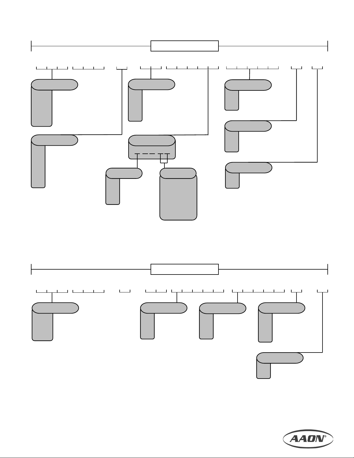
Page 17

p
3
4
2103
Figure 4.3, Module Configuration Schematic
CONFIGURATION:
M1-H-011-R-2-A-A-0-A-0
FTF-101-P-A0-00000-00000-0-0
HRA-102-A-00-00000-00000-0-0
CLF-103-C-00-210F0-610F0-S-0
SFA-104-K-C0-A0000-00000-0-0
PEC-201-K-B0-A0000-00000-0-0
FTD-203-B-B0-00000-00000-0-0
Module
configuration
numbers.
access clearances for
Table provides
required service
applicable modules.
101
201
Base model
number.
PEC FTD
10
Configuration Schematic
can be found in unit
literature
acket.
Arrows indicate
airflow.
HRA
20
CLF FTF SFA
10
17
Page 18

Note that a heat wheel module will have a 100 series
y
t
number identifying it, but will span both tiers also
utilizing a 200 series space, and effectively “skipping”
one of the top-tiered numbers.
If, for any reason, you are unable to identify any
module, or its position in the final assembly, then
consult the salesperson or project engineer.
Table 4.1, Module Code Chart
Code Description
BBA Small Blank Box
BBB Large Blank Box
CLB Cooling Coil
CLC Cooling Coil/Hot Gas Reheat Coil
CLD Electric Heat/Hot Water Coil
CLE Electric Heat
CLF Hot Water/Cooling Coil
CLG Electric Heat/Cooling Coil
CLH Electric Heat/Cooling Coil/Hot Gas Reheat Coil
CLI Cooling or Heating w/ Face Bypass
CLJ Hot Water/Cooling Coil/Hot Gas Reheat Coil
CLK Vertical Cooling Coil
CLL Cooling and Heating w/ Face Bypass
FTA Small Flat Filter
FTB Angled Filter
FTC Cartridge Filter
FTD Bag Filter
FTF Large Flat Filter
HRA Energy Recovery Wheel
MBA Vertical Damper Mixing Box
MBB Horizontal Damper (top) Mixing Box
MBC Horizontal (bottom)/Vertical Damper Mixing Box
MBD Vertical Damper/Filter Mixing Box
MBE Horizontal Damper (top)/Filter Mixing Box
MBF Horizontal Damper (bottom) Mixing Box
MBG Filter Mixing Box (no damper)
MBH Vertical/Horizontal (top) Damper Mixing Box
MBI Filter/Horizontal (bottom) Damper Mixing Box
MBJ Vertical/Horizontal (top) Damper/Filter Mixing Box
MBK Vertical/Horizontal (bottom) Damper/Filter Mixing Box
PEA Power Exhaust
PHA Electric Heat
PHB Hot Water Coil
PHC Filter/Hot Water Coil
PHD Filter/Electric Heat
RFA Return Fan
RHC Hot Gas Reheat Coil
SFA Supply Fan
SFB Vertical Supply Fan
SFC Supply Fan with Top Discharge
TRA Control Box
After identifying modules and determining module
arrangement, you can begin connecting the modules.
Modules are to be connected with nuts and bolts that
are shipped with the unit. Bolt holes are located inside
the module frames near the corners, and in the base
rail below the outside bottom corners of the module
(due to various design criteria, some modules may
have additional bolt holes along the inside of the
module top, and should be used if present). Align
modules, and insert bolts through the bolt holes of two
adjacent modules, and secure with nuts to pull the two
modules together tightly. Every bolt hole must be
used to ensure a tight seal between modules, and a
structurally stable assembly.
NOTE
All nuts, bolts, and gasketing required for assembl
are packaged and shipped with unassembled uni
orders.
Figure 4.4, Bolted Base Rail
Sealing
It is very important to keep outside air from infiltrating
the unit cabinet. Seal all piping penetrations with
Armaflex, Permagum, or other suitable sealant. Also
seal around drain connections, electrical connections,
and all other inlets where air may enter the cabinet.
This is especially important when the unit is installed in
an unconditioned area.
Cooling Equipment
Air Handler Equipped with Refrigerant Coil (DX)
This section is not intended to provide all the
information required by the designer or installer of the
refrigerant piping between the condensing units and
the air handler. The appropriate sections of the
ASHRAE Guide and the ASME standards should be
used for final information. Acceptable system design
and installation will include consideration as follows:
18
Page 19

− Piping from the condensing unit to the indoor air
handler is the responsibility of the installing
contractor.
− Only clean “ACR” tubing should be used.
− Piping should conform to generally accepted
practices and codes.
− Care must be taken not to cross the circuits on
multiple circuit systems.
− Once piped, the interconnecting piping and air
handler MUST BE evacuated to 50 microns or
less; leak checked and charged with refrigerant.
− Make sure air handler thermal expansion valve
bulb is mounted with good thermal contact on the
correct suction line on a horizontal section, close
to the evaporator in the 4 or 8 o’clock position and
well insulated. Care must be taken to ensure the
bulb is mounted on the correct suction line on
multiple circuit systems.
− The suction line (and hot gas bypass line if
present) should be insulated for its entire length
Lines should be fastened and supported according to
local codes.
Air Handler Equipped with Chilled Water Coil
Water supply lines must be insulated with closed cell
type pipe insulation or insulation that includes a vapor
barrier. Lines should be properly fastened, drained
and supported according to local code requirements.
Heating Equipment
When heat is called for, the cooling section is
inoperable except for the indoor blower motor. Actual
heating is accomplished by the air handling unit with
hot water, steam or electric heating capabilities.
Air Handler Equipped with Hot Water Coil
Water supply lines must be insulated, properly
fastened, drained and supported according to local
code requirements.
Air Handler Equipped with Steam Coils
The air handling unit MUST BE installed high enough
to allow for a minimum of one foot (1’) condensate
drop leg off of the steam coil (or as recommended by
the steam trap manufacturer). Lines should be
insulated with approved insulation and be properly
fastened, sloped and supported according to local
code requirements.
Air Handler Equipped with Electric Heating
INSTALLATION IS TO BE ADJUSTED TO OBTAIN
AN AIR TEMPERATURE RISE WITHIN THE RANGE
SPECIFIED ON THE RATING PLATE.
Heating is accomplished by passing electrical current
through a specified amount of resistance heaters
which will produce the required heat. The indoor
blower motor will energize at the same time as the
heaters. Wiring to the air handler must be done in
accordance with local electrical codes and/or
standards. Check specified electrical rating and install
with proper wire size.
Condensate Piping
If the air handler is equipped with cooling, a drain trap
must be connected to the drain pan at the unit. A
condensate connection is provided on each side of the
unit. Condensate piping should be installed according
to local codes. The line should be the same pipe size
as the drain nipple and should pitch downward toward
the building drain.
All cooling coils must have drain pans equipped with
“P” traps to avoid pulling air from outside the unit back
through the drain line. The “P” trap is factory supplied,
and is shipped loose in the control access
compartment for field installation. A plug is provided
for the unused condensate connection. The trap
should be located in warm ambient spaces. An
additional drain pan may be installed under the air
handler, and should include a separate drain line for
overflow from the primary drain. An air break should
be used with long runs of condensate lines.
Drain pans in any air conditioning equipment, even
when they have a built-in slope to the drain, will have
moisture present and will require periodic cleaning to
prevent any build-up of algae or bacteria. Cleaning of
the drain pans will also prevent any possible plugging
of the drain lines, and overflow of the pan itself. Some
means to clean out the “P” trap should be provided.
Only qualified personnel should clean drain pans,
drain lines, or the insides of equipment.
Electrical
Check the unit data plate to make sure it agrees with
the power supply. Connect power to the unit
according to the wiring diagram provided with the unit.
The power and control wiring may be brought in
through the holes provided on the unit. Protect the
branch circuit in accordance with code requirements.
19
Page 20

If the control wires are to run inside the same conduit,
use 600-volt wire or as required by applicable codes.
The units must be electrically grounded in accordance
with the National Electric Code, ANSI / UL 1995 when
installed if an external source is utilized; in Canada
use current C.S.A. Standard C22.2, No. 236,
Canadian Electric Code Part 1.
Power wiring is to the unit terminal block. The
manufacturer has done all wiring beyond this point.
Power can be applied to the unit after the control
wiring is connected, and start up checks are complete.
Thermostat
The low voltage room thermostat should be located on
an inside wall 4 to 5 feet a above the floor where it will
not be subjected to drafts, sun exposure or heat from
electrical fixtures or appliances. Control wire size
must be large enough to prevent excess voltage drop
that may cause improper operation of the equipment.
Follow manufacturer’s instructions enclosed with
thermostat for general installation procedure.
Filters
Open filter access door and slide correct filter in with
arrow pointing towards the blower in the direction of
airflow.
5. Refrigerant Piping &
Line Sizing Information
THIS SECTION IS FOR INFORMATION ONLY, AND
IS NOT INTENDED TO PROVIDE ALL THE
INFORMATION REQUIRED BY THE DESIGNER OR
INSTALLER OF THE REFRIGERANT PIPING
BETWEEN THE CONDENSING UNITS AND THE
LOW SIDE COMPONENTS. AAON, INC. IS NOT
RESPONSIBLE FOR INTERCONNECTING
REFRIGERANT PIPING. THE APPROPRIATE
SECTIONS OF THE ASHRAE GUIDE AND THE
ASME STANDARDS SHOULD BE USED FOR FINAL
INFORMATION.
The piping between the condenser and low side must
assure:
1. Minimum pressure drop, and
2. Continuous oil return, and
3. Prevention of liquid refrigerant slugging,
or carryover
Acceptable system design and installation will include
consideration as follows.
General
Use only clean type L copper tubing (type K for
underground) that has been joined with high
temperature brazing alloy.
The pipe sizes must be selected to meet the actual
installation conditions, and not simply based on
the connection sizes at the evaporator and/or
condensing unit.
When sizing refrigerant lines, cost considerations favor
keeping line sizes as small as possible. However,
excessive suction or discharge line pressure drops
cause loss of compressor capacity and increased
power usage, resulting in reduced system efficiency.
Furthermore, excessive liquid line pressure drops can
cause the liquid refrigerant to flash resulting in faulty
expansion valve operation.
Correct sizing must be based on minimizing cost and
maximizing efficiency. Pressure drop calculations are
referenced as normal pressure loss associated with a
change in saturation temperature of the refrigerant.
Typically, the refrigeration system will be sized for
pressure losses of 2°F or less for each segment of the
discharge, suction, and liquid lines.
Liquid Line Piping
Systems are normally designed so that the pressure
drop in the liquid line (due to friction) is not greater
than that corresponding to an approximate 1 to 2°F
change in saturation temperature. Liquid sub cooling
is the only method of overcoming the liquid line
pressure loss to guarantee presence of liquid at the
expansion device in the evaporator.
If the sub cooling is insufficient, flashing will occur
within the liquid line and the system efficiency will
suffer. Accessories such as solenoid valves, filter
driers, and hand valves, as well as the actual pipe,
fittings between the receiver, or condenser outlet, and
the metering device cause friction pressure drops in
the liquid line. Liquid line risers are also a source of
pressure loss, and add to the total loss of the liquid
line. The loss due to risers is approximately 0.5 PSI
per foot of liquid lift. The total loss is the sum of all
friction losses plus the pressure loss from liquid risers.
If the refrigeration system has no liquid risers, and the
evaporator is below the condenser/receiver, then it
benefits from a gain in pressure due to liquid weight,
and can tolerate larger friction losses without flashing.
When flashing takes place, regardless of the routing of
20
Page 21

the liquid lines, the overall efficiency is reduced, and
the system may malfunction.
A pressure loss of 3 psi in the liquid line results in a
1°F loss of sub-cooling temperature with R-22.
Table 5.1, R-22 Liquid Line Capacity w/ 3 PSI (1°F)
°
Pressure Loss per 100 Feet at 100
Line Size (In.) Max. Tons
1/2 4.0
5/8 7.6
7/8 19.1
F Liquid
Note: The equivalent feet for a piping system must include the
equivalent length of straight tubing for all the fittings, and any valves
that are added to the system.
Suction Line Piping
Suction lines are more critical than liquid lines and
discharge lines from a design and construction
standpoint. The proper return of oil to the
compressor(s) is critical, and depends on maintaining
sufficient velocity in the suction lines to carry the oil
along with the refrigerant gas. Simultaneously, high
refrigerant velocities in the suction line bring highpressure losses that reduce capacity.
Suction lines should be sized to:
1. Provide minimum pressure drop at full load,
and
2. return oil from the evaporator to the
compressor under minimum load conditions,
and
3. prevent oil from draining from an active
evaporator into an idle one.
Over sizing of suction lines results in poor oil return to
the compressor. Therefore, minimum suction gas
velocity of 750 fpm in horizontal runs, and 1500 fpm in
vertical runs is necessary.
A pressure drop in the suction line reduces a system’s
capacity because it forces the compressor to operate
at a lower suction pressure to maintain a desired
evaporating temperature in the coil. The suction line is
normally sized to have a pressure drop from friction no
greater than the equivalent of an approximate 2°F
change in saturation temperature.
If oil is entrained up vertical risers at partial loads, and
pipe size must be reduced to provide sufficient gas
velocity, then greater pressure drops are imposed at
full load. These pressure drops can usually be
compensated for by over sizing the horizontal and
down-run lines, and components. As shown in Figure
5.1, a double suction riser may be required in order to
return oil at partial load.
Figure 5.1, Double Suction Riser Example
Evaporator
Suction Line to
Compressor
All vertical suction risers should be checked to confirm
that oil will be returned to the compressor. Use the
tables in this section for pipe sizing information.
Table 5.2, Minimum Tons of Capacity to Carry Oil Up a
°
Suction Riser at 40
Line Size (In.) Min. Tons
All suction lines must be pitched in the direction of flow
and supported to maintain their position. Full
insulation must be used between the evaporator and
condensing unit.
Suction accumulators are not included with AAON
equipment (except with air source heat pumps), and
must be field furnished and installed if required by job
conditions.
Table 5.3, R-22 Suction Line Capacity w/ 3 PSI (2°F)
Pressure Loss per 100 Feet at 40
Line Size (In.) Max. Tons
Discharge Lines
Discharge (hot-gas) lines should be designed to:
F Saturated Suction
5/8 .3
7/8 .8
1 1/8 1.6
1 3/8 2.8
1 5/8 4.4
°
F Saturated Suction
5/8 1.1
7/8 2.7
1 1/8 5.5
1 3/8 9.3
1 5/8 14.9
21
Page 22

1. Avoid trapping oil at part-load operation,
and
2. prevent condensed refrigerant and oil in
the line from draining back to the head of
the compressor, and
3. avoid developing excessive noise from
either hot-gas pulsations, compressor
vibrations, or both.
Pressure loss in hot-gas lines increases the required
compressor power per unit of refrigeration, and
decreases the compressor capacity. Pressure drop is
minimized by over sizing the lines for low friction
losses while maintaining refrigerant line velocities to
entrain and carry oil at all loading conditions. Normally,
pressure drop is designed not to exceed the equivalent
of a 2°F change in saturation temperature, while
recommended sizing is based on a 1°F change in
saturation temperature.
Other Piping
Hot Gas Bypass Lines (Optional)
The hot gas bypass option is a system that maintains
evaporator pressure at or above a minimum value in
order to prevent the coil from freezing, and to keep
refrigerant velocity high enough for proper oil return
when operating at a light load.
Pressure drop in the hot gas line is normally designed
not to exceed the equivalent of a 2°F change in
saturation temperature with R-22. See Table 5.4
below that is based on a 1°F change in saturation
temperature.
Hot gas bypass lines must be insulated to minimize
heat loss and condensation of gas inside the piping
and to prevent injury from high temperature surfaces.
See Section 8 of this manual for more information
about hot gas bypass.
Table 5.4, R-22 Hot Gas Bypass Line Capacity w/ 3 PSI
(1°F) Pressure Loss per 100 Feet at 40°F Saturated
Suction
Line Size (In.) Tons
1/2 .9
5/8 1.6
7/8 4.1
1 1/8 8.4
1 3/8 14.2
Minimum Gas Velocities for
Oil Transport in Risers
On multiple compressor installations, the lowest
possible system loading should be calculated with a
riser size selected to give at least the minimum
capacity for successful oil transport. Some
installations will have excessive pressure drop at
maximum load when multiple compressors exist with
capacity control, a vertical hot-gas line, and that are
sized to transport oil at minimum load. A double riser,
or a single riser with an oil separator can be used to
correct this problem.
Double Hot-Gas Risers
A double hot-gas riser can be used the same way it is
used in a suction line. Figure 5.1 shows the double
riser principle.
Single Riser and Oil Separator
Alternatively, an oil separator located in the discharge
line, just before the riser, permits sizing the riser for a
low-pressure drop. Any oil draining back down the
riser accumulates in the oil separator. With large
multiple compressors, the capacity of the separator
may dictate the use of individual units for each
compressor located between the discharge line, and
the main discharge header. Horizontal lines should be
level, or pitched downward in the direction of gas flow
in order to facilitate travel of oil through the system,
and back to the compressor.
Piping to Prevent Liquid and Oil from Draining to
Compressor Head
Whenever the condenser is located above the
compressor, the hot-gas line should be trapped near
the compressor before rising to the condenser,
especially if the hot-gas riser is long. This minimizes
the possibility that refrigerant, condensed in the line
during off cycles, will drain back to the head of the
compressor. Also, any oil traveling up the pipe wall
will not drain back to the compressor head.
The loop in the hot-gas line serves as a reservoir and
traps liquid resulting from condensation in the line
during shutdown, thus preventing gravity drainage of
liquid, and oil back to the compressor head. A small
high-pressure float drainer should be installed at the
bottom of the trap to drain significant amounts of
refrigerant condensate to a low side component such
as a suction accumulator, or low-pressure receiver.
22
Page 23

This float prevents excessive liquid buildup in the trap,
and reduces the potential for “liquid hammer” when the
compressor is restarted.
In order to prevent gas from active compressors from
condensing on the heads of idle compressors in
multiple compressor arrangements, each discharge
line should have a check valve. For singlecompressor applications, a tightly closing check valve
should be installed in the hot-gas line of the
compressor whenever the condenser, and the receiver
ambient temperature are higher than that of the
compressor. The check valve prevents refrigerant
from boiling off in the condenser, or receiver, and
condensing on the compressor heads during off
cycles. The check valve should be a piston type that
closes by gravity when the compressor stops running.
ECat32 Refrigerant Piping Calculator
This program contained in the AAON
Engineering Tools section of AAON’s
ECat32 equipment rating and selection
software can be used to size liquid,
discharge, and suction lines.
The program calculates the equivalent
length as the sum of the actual length plus
the number of elbows times the equivalent
length per elbow. Pressure drop of other
components should be incorporated using
the ASHRAE Refrigeration Handbook to
determine fitting, and valve losses in
equivalent lengths of pipe. Additional losses
should be added to the total length before
calculation.
Figure 5.2, AAON Ecat32 Screenshot: Refrigerant Piping Calculator
Table 5.5, Fitting Losses in Equivalent Feet of
Straight Copper Tubing
Tubing
Size
(In.)
1/2 1.4 .9 2.3 .7 1.1 2.3
5/8 1.6 1.0 2.5 .8 1.3 2.5
7/8 2.0 1.4 3.2 .9 1.6 3.2
1 1/8 2.6 1.7 4.1 1.3 2.1 4.1
1 3/8 3.3 2.3 5.6 1.7 3.0 5.6
1 5/8 4.0 2.6 6.3 2.1 3.4 6.3
Note: The equivalent feet for a piping system must include the
equivalent length of straight tubing for all the fittings, and any valves
that are added to the system.
90°
Std.
90°
Long
Rad.
90°
Street
45°
Std.
45°
Street
180°
Std.
23
Page 24

6. Start-Up
t
t
y
r
p
General
Equipment power should be on at least 24 hours
before start-up to allow the crankcase heater to
boil off refrigerant that may have accumulated in
the com
ONLY QUALIFIED, AUTHORIZED PERSONNEL
SHOULD POWER ON, OR START-UP THIS
EQUIPMENT.
The use of common sense, and good practice in the
installation, and start-up of equipment will prevent
many potential problems with the system in the future.
Before starting up the equipment, building construction
should be complete, and start-up personnel should:
− Have a working knowledge of general HVAC
− Be familiar with unit functions, features,
− Have appropriate literature on hand for
Equipment operation during construction is no
recommended. Construction site pollution can
affect unit operation, and seriously degrade
performance. Operation during construction will
void all manufacturer’s warranties.
Before the structure is occupied, the installation,
and/or start-up personnel must take three essential
steps:
1. Check Out
2. Start-Up
3. Commissioning
Check Out
Equipment should be thoroughly checked for loose
wiring, a free spinning blower wheel, and well fitting
ressor oil.
and mechanical commissioning procedures
and practices;
optional unit accessories, and all control
sequences;
consultation.
CAUTION
CAUTION
access panels. Air handlers should not be operated
without proper ductwork and access panels installed,
except as required during start-up and air balancing.
1. Check all electrical connections to be sure
they are tight.
2. Open all access panels, and remove all
shipping screws, or restraints.
3. Clean out any debris that may have been left.
4. Check belt alignment, and tightness of fan
drives.
5. Check bearing locking collars, and fan wheel
set screws for tightness.
6. Turn fan wheels to assure free rotation.
7. Ensure electrical supply matches the unit
nameplate.
8. Ensure condensate lines are connected, and
glued.
9. Check local codes for any special provisions.
10. Replace, and/or close all access panels.
11. Ensure that return, and/or supply dampers in
ductwork are open.
Start-Up
Failure to adhere to the following start-up
procedures will void all manufacturer’s warranties.
Install gauges, voltmeter, and ammeter before startup. Observe refrigerant pressures during initial
operation. Note, and determine the cause of any
excessive sound, or vibration. Follow start-up
procedures outlined below to start each piece of
equipment.
NOTE
Procedures
Completed factory test sheets are in the equipmen
literature packet shipped inside the unit. Factor
run-test readings recorded on the test sheets fo
may be helpful to reference during start-up.
Electric Heating Section:
1. Perform final visual inspection. Check all
equipment, ductwork, and piping to verify that
all work is complete, and equipment is
NOTE
24
Page 25

properly installed and mounted. Improperly
installed equipment, or ductwork can affect
readings.
2. Ensure there is no construction debris in the
unit.
3. Check the unit for external damage.
4. Note all accessories installed.
5. Install a filter of the proper size and type.
6. Check all terminal blocks, fuses, fuse blocks,
and contactors for correctness.
7. Check all high and low voltage wiring
connections for correctness, and tightness.
8. Check unit for correct incoming voltage per the
data plate.
9. Check the security of the locking system on all
blower bearings
10. Turn the unit power on.
11. Turn the unit blower on, and check for correct
rotation.
12. If correct, take blower amp readings, and
compare to see if the amp draw is within the
safety factor area of the motor. Once correct,
turn blower off.
13. Turn on the first stage of heating
− Check amp draw of each element of
each stage
− Ensure blower started w/ electric heat
− Check for temperature rise across
heating section while all stages are on
− If temperature rise is within range, turn
all heating calls off
− Check to see that blower stops
14. If equipped with an economizer, when testing
of cooling circuits is complete, turn cooling
circuits off, and leave blower running.
15. Call for the economizer circuit to operate.
16. Check for economizer blades to open fully with
no binding.
17. If equipped with power exhaust, check that it
will operate with the economizer circuit.
18. Take power exhaust motor amp readings.
Refrigerant (DX) Cooling Section:
1. Perform final visual inspection. Check all
equipment, ductwork, and piping to verify that
all work is complete, and equipment is
properly installed and mounted. Improperly
installed equipment, or ductwork can affect
readings.
2. Perform condenser start-up checks in addition
to these air handler checks according to the
condenser manufacturer’s instructions.
3. Ensure there is no construction debris in the
unit.
4. Check the unit for external damage.
5. Note all accessories installed.
6. Install filter of the proper size and type.
7. Ensure that drain P-trap is installed.
8. Check all terminal blocks, fuses, fuse blocks,
and contactors for correctness.
9. Check all high, and low voltage wiring
connections for tightness. Check unit for
correct incoming voltage per the data plate.
10. Check the security of the locking system on all
blower bearings
11. Turn the unit power on.
12. Turn the unit blower on, and check for correct
rotation.
13. If correct, take blower amp readings, and
compare to see if the amp draw is within the
safety factor area of the motor.
14. Check, and record ambient temperature.
15. Check for Guaranteed Off Timers (GOT),
and/or Time Delay Relays (TDR).
16. Start the first stage cooling circuit, and blower
circuit.
17. After all stages of cooling have been on for at
least five minutes, record the return air
temperature, and supply air temperature.
18. Check the temperature difference across the
evaporator coil.
19. If equipped with an economizer, after testing
of cooling circuits is complete, turn cooling
circuits off, and leave blower running.
20. Call for the economizer circuit to operate.
21. Check for economizer blades to open fully with
no binding.
22. If equipped with power exhaust, check that it
will operate with the economizer circuit.
23. Take power exhaust motor amp readings.
Optional Equipment
Operation of each of the following, if equipped in the
unit, must be checked according to that item’s
manufacturer’s specifications:
− Clogged filter switch
− Magnehelic gauge
− Supply air smoke detector
− Return air smoke detector
− Return air fire stat
− Supply air fire stat
− Phase and brownout monitor
− Ground fault circuit interrupter outlet
− Low limit control
− Duct stats
− Hot gas reheat
− Hot gas bypass
− Compressor lockout/ Low ambient
− Heat wheel drive motor
− Null pressure switch
25
Page 26
Commissioning
The commissioning of an air conditioning system is the
process of achieving, verifying, and documenting the
performance of that system to meet the operational
needs of the building. This may not be a formal
process in smaller structures, such as a normal
residence, but some form of owner acceptance will
occur. Adjustments made during the commissioning
phase may include air, or water balancing, or
configuration of controls, and operational sequences.
Air Balancing
High performance systems commonly have complex
air distribution and fan systems. Unqualified personnel
should not attempt to adjust fan operation, or air
circulation, as all systems have unique operating
characteristics. Professional air balance specialists
should be employed to establish actual operating
conditions, and to configure the air delivery system for
optimal performance.
Water Balancing
A hydronic specialist with a complete working
knowledge of water systems, controls, and operation
must be employed to properly balance the entire
system. Unqualified personnel should not attempt to
manipulate temperatures, pressures, or flow rates, as
all systems have unique operating characteristics, and
improper balancing can result in undesirable noises
and operation.
Controls
A variety of controls and electrical accessories may be
provided with the equipment.
Identify the controls on each unit by consulting
appropriate submittal, or order documents, and
operate according to the control manufacturer’s
instructions. If you cannot locate installation,
operation, or maintenance information for the specific
controls, then contact your sales
control manufacturer for assistance.
Do not alter factory wiring. Deviation from the
supplied wiring diagram will void all warranties,
and may result in equipment damage or personal
injury. Contact the factory with wiring
discrepancies.
WARNING
representative, or the
7. Operation & Maintenance
General
Immediately following building occupancy, the air
conditioning system requires a maintenance schedule
to assure continued successful operation. A
maintenance program similar to the example given
below should be scheduled for routine maintenance of
this equipment in order to provide continued efficient,
and reliable operation for the owner.
Maintenance Schedule
One week after start-up:
− Check refrigerant charge. Evacuate and repair
coil if leaking.
− Adjust belt tension on all fan drives.
− Check filters for cleanliness. Measure pressure
loss if applicable. Replace if necessary.
− Check cycling of compressors, fans, and valves.
Correct unusual cycling.
Monthly:
− Lubricate bearings if operating continuously at
1500 rpm, or higher, or in other extreme
conditions.
− Check cleanliness of filters, and replace if
necessary.
− Check cooling coil drain pan to assure proper
drainage.
− Inspect evaporator, and condenser coils. Clean if
dirty, or obstructed in any way.
Quarterly:
− Lubricate bearings if operating at 1000 rpm, or
less, and in temperatures less than 150°F, or other
extreme conditions.
− Check damper operation for freedom of
movement. Correct any binding that may occur.
− Check belts, and pulleys on all fan drives for
tension, and unusual wear.
− Check operation of heating, and cooling section if
seasonal.
− Check inlet, and outlet air temperatures.
Determine cause for abnormal changes.
Annually:
− Clean the condenser, and evaporator coils with
steam, or a non-corrosive coil cleaner.
26
Page 27

− Clean the drain line, “P” trap, and condensate pan.
− Check refrigerant pressures, and temperatures
every Spring, and correct unusual operation.
− Check heating section every Fall. Check all
electrical connections for tightness, and check
heater elements for indications of overheating.
Determine cause and replace elements if
necessary.
Blower Assembly
AAON air handlers use backward inclined airfoil
blower wheels that are non-overloading, very efficient,
and very easy to clean. Clean blower wheels are
necessary to reduce electrical use, maintain capacity
and reduce stress on the unit. The blower wheel, and
blower section need to be inspected periodically, and
cleaned of dust, or debris.
To inspect and clean the blower; set thermostat to the
“OFF” position; turn the electrical power to the unit to
the “OFF” position at the disconnect switch. Clean the
assembly, check the bearings for looseness, inspect
the belt condition and tightness, check screws for
tightness, rotate blower wheel while listening close to
each bearing to check for noise or roughness in the
bearing, which indicates a failing bearing.
Bearings
AAON uses pre-lubricated bearings, and bearings that
have been sized for an average failure rate of 50%
after 200,000 hours, or 22.8 years, of operation (see
heading “Lubrication” in this section for more
information). The bearing sizing tables below are
based on rotational speeds, and radial loading.
However, the alignment of the bearing to the shaft,
and the security of the bearing inner race to the shaft
will greatly affect bearing life. Even though the
manufacturer is responsible for bearing tolerances,
and mounting design, the installer is advised to
check the security of the bearing locking system
before start-up
.
Table 7.1, Bearing Setscrew Torque Recommendations
Size
(In.)
1 1/4 - 28 66 - 85 8 - 32 63 - 70
1 3/16 1/4 - 28 66 - 85 8 - 32 63 - 70
1 7/16 5/16 - 24 126 - 164 10 - 24 81 - 90
1 7/8 3/8 - 24 228 - 296 1/4 - 20 162 - 180
Setscrew Locking Skewzloc Locking Shaft
Thread Torque (In-Lbs) Thread Torque (In-Lbs)
Belts
Belt drive misalignment is one of the most common
causes of premature belt failure. A belt can be
destroyed in a matter of days if the drives have been
aligned incorrectly.
The most common tool for measuring misalignment is
a straightedge. Hold the straightedge flush across one
pulley to gauge the degree of misalignment of the two
sheaves. The maximum allowed misalignment is one
half degree of angular misalignment, and 1/10
inch per foot between sheave centers for parallel
misalignment.
Figure 7.1, Angular Misalignment
Pulley Pulley
Straightedge
Belt
Corrected by moving the position of the motor.
Figure 7.2, Parallel Misalignment
Pulley
Straightedge
Pulley
Belt
Corrected by adjusting sheaves on one, or both shafts.
Frequent belt tensioning is highly recommended. Most
belt manufacturers would suggest a retensioning after
as little as 8 hours of operation. A simplified method of
adjusting tension is to gauge the amount of force
required to deflect the belt by 1/64
th
of an inch per inch
of distance between sheave centers. For example, if
the sheaves are 20 inches apart, then the amount of
deflection with the forces listed below is 20/64
of an inch.
Deflections required for:
“A” belts: 4 to 6 lbs.
“B” belts: 6 to 10 lbs.
“C” belts: 10 to 18 lbs.
th
of an
th
(5/16th)
27
Page 28

Figure 7.3, Belt Deflection
Sheave Centers
Force
Deflection = 1/64th in.
per inch of length
Coils
Coils should be inspected and cleaned annually to
ensure there is no obstruction to airflow.
Evaporator (Indoor/Cooling Coil)
Dirty evaporator coils will eventually freeze up, and
often result in a time consuming, and expensive
service call. Clean filters will help to prevent dirt from
accumulating on the evaporator, however the
evaporator should be cleaned annually with a soft
bristled brush, and/or a non-corrosive coil cleaning
solution.
Condenser (Outdoor Coil)
One of the most overlooked maintenance
requirements is the need to keep air moving freely
across air-cooled condensing coils. Dirty condensers,
like evaporators, can significantly increase cooling
costs during the year. As a minimum, clean the
condenser coil at the beginning of each cooling
season. It is preferable to use a medium pressure
water spray from the inside of the condenser cabinet
with a non-corrosive coil cleaning solution. TURN
OFF all power to the unit before cleaning.
Comb out any visible exterior fin damage to help
maintain unit efficiency. Clean the fan blades if they
are dirty. Always check condenser fan blades to
ensure unobstructed, free rotation after manipulating
the unit cabinet in any way, and before turning power
back on to the condenser.
Refrigeration Cycle
Satisfactory performance of the refrigeration cycle can
be determined by measuring suction line superheat.
In order to determine if refrigerant flowing from the
evaporator is dry, ensure that the system has enough
refrigerant to produce liquid line subcooling, but not so
much to cause abnormally high condensing
temperatures (and pressures). Refrigerant cycle
analysis is best performed in conditions that approach
the conditions where the air conditioner will be
expected to operate.
Superheat
Superheat is the extra heat in vapor when at a
temperature higher than the saturation temperature
corresponding to its pressure. To determine the
superheat, measure the temperature of the suction line
(insulate the temperature probe from surrounding air),
and read the suction line pressure. The difference
between the suction line temperature, and the
temperature indicated on a refrigerant pressuretemperature chart (see inside back cover) at the
suction line pressure is the degree of superheat.
Subcooling
Subcooling enhances unit capacity, and assures that
only liquid appears at the threshold of the expansion
valve, also prolonging expansion valve life, and
providing better expansion valve control. Subcooling
is determined by measuring the difference between
the temperature of liquid refrigerant as it leaves the
condenser coil, and the temperature indicated on a
pressure-temperature chart at the pressure measured
in the liquid line.
Determining Charge
Table 7.2 shows expected discharge superheat levels
in R-22 systems when properly charged. To
determine proper charge using this table, do the
following:
1. Connect manifold gauges to the unit, and allow the
unit to operate for at least 5 minutes in order to
allow system pressures to stabilize.
2. Attach thermocouples to discharge line, and take
temperature measurement.
3. Measure suction, and discharge pressures, and
convert to saturated temperatures using the
temperature-pressure chart.
4. Subtract saturated condensing temperature from
measured discharge line temperature to get
discharge line superheat.
28
Page 29

5. If the discharge superheat measured does not
agree with the values in Table 7.2, then adjust the
charge (see heading “Charging” in this section).
If the superheat is 5°F higher than shown, then the
system is undercharged.
If the superheat is 5°F lower than shown, then the
system is overcharged.
Table 7.2, R-22 Discharge Superheat Temperatures, °F
Saturated
Suction
Temp.
34 64.2 67.6 70.9 74.0 77.0 79.7 82.1
36 62.4 65.7 68.9 72.0 75.0 77.7 80.1
38 60.7 63.8 67.0 70.1 73.0 75.7 78.2
40 59.0 62.0 65.1 68.1 71.0 73.8 76.3
42 57.3 60.3 63.3 66.3 69.1 71.9 74.4
44 55.7 58.6 61.5 64.4 67.3 70.0 72.6
46 54.0 56.8 59.7 62.6 65.5 68.2 70.8
48 52.4 55.2 58.0 60.8 63.7 66.4 69.1
50 50.9 53.5 56.3 59.1 61.9 64.7 67.3
52 49.3 51.8 54.5 57.3 60.1 62.9 65.6
54 47.7 50.2 52.8 55.6 58.4 61.2 63.9
Saturated Condensing Temperature
100 105 110 115 120 125 130
Charging
The following charging methods apply to TXV systems
only as manufactured and sold by AAON.
The system should be charged during warm weather,
however there are times when systems must be
charged during colder weather. Charging in cold
weather, while not as simple as it would otherwise be,
is possible to accomplish contrary to popular belief.
Warm Weather Charging
If you are charging in warm, or hot weather, above
outdoor ambient temperatures of 65°F, then use the
standard superheat charging method by first
determining the superheat as described in the
previous section, “Refrigerant Cycle”. If the system is
undercharged, add refrigerant according to Table 7.2.
If the system is overcharged, then recover refrigerant
according to Table 7.2.
Cold Weather Charging
If you are charging in cool, or cold weather, below
outdoor ambient temperatures of 65°F, then you
should “weigh in” the refrigerant charge. Therefore,
you must have a refrigerant scale in order to charge
during cold weather, and if you are complying with all
of the U.S. Environmental Protection Agency’s laws
governing the use of refrigerants, then you will have a
refrigerant scale available to use.
First, recover all refrigerant from the system, and
evacuate to .05 microns. Next, create a false load on
the system by running the
building heat long enough
to hold an indoor temperature between 70°F and 80°F
for the charging period. Using a scale, weigh in the
refrigerant nameplate charge. In AAON condensing
units, the nameplate charge is enough refrigerant for
the condenser, and 15 feet of line set. If you are not
using an AAON condensing unit, then you must check
that manufacturer’s literature for refrigerant charge
specifications.
Additional line length, beyond 15 feet with AAON
condensers, will require more refrigerant. Use Table
7.3 to determine how much refrigerant should be
weighed into the system based on line set diameters,
and lengths.
In extremely cold outdoor temperatures, it is helpful to
warm up the refrigerant drum. Electric heating pads,
an electric blanket, or simply a bucket of hot water can
be used.
Table 7.3, Weight of R-22 in Type L Copper Tubing
(Pounds per 100 Feet)
Line Size (In.)
3/8 3.8 .08
1/2 7.4 .16
5/8 11.9 .26
7/8 23.9 .51
1 1/8 40.7 .87
1 3/8 60.1 1.29
1 5/8 - 1.82
Remember that as you add, or take away refrigerant,
system pressures must stabilize to obtain accurate
readings. The time required for proper stabilization
increases with the length, and overall size of the line
set, and can vary by the amount of refrigerant in the
system. Patience is required to properly charge any
system.
If you are charging the system for the first time after
installation, and start-up, then you are advised to
return after a full week of cooling operation, as outlined
in “Maintenance Schedule” of this section, in order to
check that refrigerant is cycling properly throughout
the system.
Liquid at 100°F Suction at 40°F
29
Page 30

Heating
Electric
Set thermostat in the heat mode; call for heat to
engage all electric heat strips. Check blower for
proper rotation and voltage. Measure the amperage
and voltage. Compare them to the nameplate data.
If applicable, check remote heat pump condenser as
per the manufacturer’s recommendations.
Steam or Hot Water
Set thermostat in the heat mode. Observe supply
blower for proper rotation and voltage. Check boiler or
hot water operation according to the manufacturer’s
instructions. Check control flow valves for correct
operation and settings per the manufacturer’s
instructions.
Cleaning
Inspect and clean unit interior at the beginning of each
heating and cooling season and as operating
conditions require
.
Chilled Water
Check remote chiller operations as per the
manufacturer’s instructions. Check coolant flow valves
for correct operation and settings.
Lubrication
Most motors and bearings are permanently lubricated.
Some applications, however, will require that bearings
be re-lubricated periodically. The schedule will
depend on the operating duty, temperature variations
or other atmospheric conditions.
For bearings equipped with lubrication fittings the
lubrication schedule is dependent on operating
temperatures, and rotational speeds as shown in table
5 below. Lithium based grease conforming to an NLGI
grade No. 2 consistency is recommended. This
medium viscosity, low torque grease is rust inhibiting,
and water-resistant. It is satisfactory for operating
temperatures in the range of –10°F to 250°F.
Bearings should only be re-lubricated when at normal
operating temperatures, and not running. Rotate the
fan shaft by hand, adding only enough grease to purge
the seals. A one-inch bearing has a total grease
capacity of only .25 ounces. Added grease should be
limited to .09 ounces.
Recommended greases are:
− SHELL OIL – DOLIUM R
− CHEVRON OIL – SRI No. 2
− TEXACO INC. – PREMIUM RB
Table 7.4, Fan Bearing Lubrication Schedule
Fan Speed Temperature Environment Greasing Interval
500 rpm
1000 rpm
1500 rpm
Any Speed
Any Speed
Service
DO NOT OVER
LUBRICATE!
Up to 150 °F
Up to 210 °F
Up to 210 °F
Up to 150 °F
210 - 250 °F
Clean 2 to 6 months
Clean 2 weeks to 2 months
Clean Monthly
Dirty 1 week to 1 month
Dirty Weekly
In the event the unit is not functioning correctly and a
service company is required, only a company with
service technicians qualified and experienced in both
heating and air conditioning should be permitted to
service the systems in order to keep warranties in
effect. The service tech may call the factory if
assistance is required.
BEFORE CALLING, THE MODEL AND SERIAL
NUMBER OF THE UNIT WILL BE NEEDED FOR THE
WARRANTY SERVICE DEPARTMENT TO HELP
ANSWER QUESTIONS REGARDING THE UNIT.
AAON Coil Products
Phone: 1-903-247-9242
Fax: 903-236-4463
Warranty Department
Filters
Open filter access door. Slide filters towards you and
inspect. Replace old filters with the size indicated on
each filter or as shown in Table 1.1. Be sure arrow
points toward the blower. Filters should be checked
every 30 days and replaced or cleaned as necessary.
IT IS IMPORTANT TO KEEP COILS, BLOWERS,
AND FILTERS CLEAN!
30
Page 31

8. Hot Gas Bypass
The purpose of (external) hot gas bypass
(HGBP) is to prevent coil freeze-up and
compressor damage from liquid slugging
during periods of low airflow operation, or with
low entering air temperatures.
HGBP is useful when the air conditioning
system is subject to variations in load caused
by varying air volume or large proportions of
outside air. The HGBP valve meters discharge
refrigerant gas to the distributor downstream of
the expansion valve, and at the entrance to the
evaporator distributor tubes. The quantity of
gas varies to control a constant suction
pressure, allowing more gas to flow as suction
pressure decreases.
HGBP is available, factory installed, on AAON
condensing units, and for use with modular air
handlers, and all AAON split systems, in order
to meet various design conditions. A modular
air handler selected with DX cooling can be
connected to a condensing unit that has also
been prepared for HGBP to the evaporator
coil. The option requires a third piping
connection from the matching condensing unit.
This connection must observe the same length
and height restrictions as used for the liquid
and suction piping. It is advisable to insulate
the hot gas line, especially on long piping runs.
Figure 8.2, External HGBP Piping
Compressor
Suction Line
HGBP Line
HGBP
Valve
Condenser Coil
Figure 8.1, Components of Hot Gas Bypass
Liquid Line
TXV
Isolation
Valves
Factory Piping
Field Piping
HGBP line connects to
ASC fitting between
TXV and distributor
Evaporator
Coil
31
Page 32

(
Figure 8.3, HGBP Connection to Evaporator & ASC Fitting
Air Handling Unit
Suction
Evaporator
Coil
ASC
TXV
Hot Gas
Liquid
Refrigerant Line
Connections
Figure 8.4, ASC Fitting at
Distributor, Exploded View
Refrigerant Flow (Liquid)
Expansion Valve Outlet
Distributor Ring
Distributor Nozzle
Auxiliary Side
Connector (“ASC”)
Hot Gas Bypass Line
From Condenser)
Refrigerant Flow
(Bypass Gas)
Distributor
The ASC fitting will come installed by the factory.
Should you need to re-install the ASC fitting in the
field, then do so according to the following procedure:
1. Install nozzle and ring in ASC (orientation as shown)
– remove from distributor if necessary.
2. Install ASC on distributor inlet.
3. Install expansion valve on ASC inlet.
4. Install liquid line.
5. Install hot gas bypass line.
9. Hot Gas Reheat
Although the evaporator reduces moisture content
from warm, moist air being conditioned, the space
thermostat is a dry bulb device and will not call for
refrigeration if outdoor and space temperatures are
mild but very humid and the space temperature is
satisfied. However, the humidity level may cause the
space to be uncomfortable. A reheat system is used
to correct this condition. To prompt operation of the air
conditioning system, a humidistat is required and to
avoid cooling the space excessively while removing
moisture, a coil which accepts discharge gas from the
compressor is located downstream of the evaporator.
The function of this coil is to heat the air that has been
cooled by the evaporator to approximate room
temperature. A reheat valve is installed in the
compressor discharge line to divert discharge gas to
the reheat coil when the humidistat calls for
dehumidification but returns all discharge gas to the
condenser when cooling is required.
Note: No additional piping is required for
modulating hot gas reheat!
Figure 9.1, AAON’s Modulating Reheat System
Air Handling Unit
Evaporator
Coil
Liquid Line
Field Piping
Suction Line
Reheat
Compressor
Condensing Unit
Control
Valve
Supply Air
Sensor
Reheat Coil
Control
Board
Wiring to
Reheat Control
Valve
Condenser
Coil
32
Page 33

After the room temperature thermostat is satisfied and
y
r
p
the humidistat continues to call for moisture removal,
the modulating valve will allow a controlled amount of
hot gas to enter the reheat coil. A discharge air
temperature sensor mounted within the air handling
unit provides input to an electronic control board. The
valve position is controlled to provide a specific supply
air temperature set point that is set on the control
board, or sent to the control board by a remote 0 to 10
VDC signal.
Since the controlled amount of hot gas is inserted into
the liquid line at the condensing unit, no additional
piping is necessary from the condensing unit. Only the
normal liquid and suction piping is required. The
modulating hot gas valve is factory mounted and
wired. The control board is shipped with a default
setting for a neutral discharge air temperature of 75°F.
10. HGBP & HGRH Together
See appendices A and B for individual
information about HGBP and HGRH.
If you still have questions about the
installation or operation of either HGBP o
HGRH after reading these sections, then
please contact your AAON Sales
Re
resentative.
NOTE
HGRH will always be on the 1
circuit only, and never on the second
stage circuit, when ordered on an
AAON condensing unit.
HGBP will always be on both 1
nd
stage circuits, and never only on
2
one circuit, when ordered on an AAON
condensing unit.
These rules apply even when HGRH
and HGBP exist together on the same
s
stem.
IMPORTANT!
st
stage
st
and
The only additional work required is to run the valve
control wires to the outdoor unit. The factory setting
can be overridden by connection to a 0 to 10 VDC
signal from another control system.
Unlike some other manufacturers’ cycling “on-off”
reheat control solenoid valve that are poorly regulated,
and produce unacceptable supply temperatures,
AAON’s modulating hot gas reheat system provides a
controlled supply air temperature, and will meet most
outside air requirements for handling enhanced latent
capacity. The system can be designed with the
outdoor air quantity to meet the design occupancy.
When used in a make-up air application, even up to
100%, the unit controller can maintain the neutral
supply air temperature under most conditions.
Figure 10.1, Components of Hot Gas Bypass & Hot Gas Reheat
33
Page 34

d
Figure 10.2, HGRH with External HGBP Piping
t
d
t
t
d
n
2
Stage
Condenser Coil
1
Condenser Coil
s
Stage
n
2
Stage
Comp.
1
Comp.
HGRH
Valve
HGBP
Valves
Isolation
Valves
Filter
Drier
HGBP Lines
11. AAONAIRE
The AAONAIRE
recovery wheel, which means that it can transfer both
sensible and latent energy, that is, heat and moisture,
from one air stream to another. The heat wheel is a
disc composed of spirally wound desiccant matrix
material. The wheel is divided across the center when
installed, and rotated by an electric motor at up to 60
RPM so that one half of the matrix material is exposed
at one moment to the exhaust air stream, and at the
next moment to the ventilation supply air stream. With
a heat wheel, efficiencies of 70 to 85% are achievable
for both sensible and latent energy transfer.
Figure 11 below shows the basics of a heat wheel.
For installation, maintenance, performance, or other
information, consult the AAONAIRE
Information booklet that came with your AAONAIRE
heat wheel.
Cleaning
The need for cleaning of the heat wheel will be
determined by the operating schedule, climate, and
regular contaminants of the conditioned space. The
AAONAIRE
®
Heat Wheel is “self-cleaning” in that the
®
Heat Wheel
®
Heat Wheel is a “total energy”
®
Setup
®
s
Stage
Reheat Coil
s
1
Stage
Evaporator Coil
TXV TXV
HGBP line connects to
ASC fitting between
TXV and distributor
Check Valve
Filter Drier
n
2
Factory Piping
Field Piping
Stage
Evaporator Coil
smallest particles will pass through, and larger
particles will land on the wheel surface, and will then
be blown clear as the wheel rotates into the opposite
direction of laminar flow. The primary cleaning need
will be to remove oil based aerosols that have
condensed on energy transfer surfaces. These oily
films can clog micron sized pores in the desiccant
material reducing the wheel’s efficiency. It can take
several years in a reasonably clean environment such
as a school, or an office building, for measurable
efficiency loss to occur. Dirtier air, such as that from a
kitchen, industrial or machine shop, or a smoke filled
room in a bar, will reduce efficiency in a much shorter
period of time.
To clean the wheel, remove the segments from the
wheel frame, and brush foreign material from the face.
Soak the segments in a non-acid based coil cleaner,
or another alkaline detergent, and warm water.
Massaging the matrix with your hands will increase the
cleaning action. Rinse well, and shake excess water
away before reinstalling. For applications where
frequent cleaning is required, it is advisable to keep a
second set of wheel segments on hand. While a set is
soaking, or being cleaned, the spare set can be
replaced in the wheel.
34
Page 35

Figure 11.1, AAONAIRE® “Total Energy” Heat Wheel
Motor Side Pulley Side
Outdoor Air Fresh Air Supply
Indoor Air Exhaust Air
Capacitor
P.C.S. Motor
“Pulley Side” View
Pulley Drive Belts
Rim Diameter Seal
Rotation
Bearing Access Cover
Dessicant Energy
Recovery Wheel with 8
Removable Segments
35
Page 36

12. Troubleshooting
Common Problems
Table 12.1, Problems, Causes, & Solutions
Problem Possible Cause Solutions
Frosted evaporator coil, low
suction pressure
Unit runs, but supplies warm air Loss of refrigerant
Compressor starts, but opens
high pressure control
High suction pressure, but low
superheat
Unit operates continuously Low refrigerant charge
Restricted air flow
Low fan speed
Reversed blower rotation
Low refrigerant charge
Dead expansion valve element
Plugged filter-drier
Refrigerant over-charged
Air in condenser coil
Condenser fan dead
Condenser coil dirty
Oversized expansion valve
Poor sensing bulb location
Low superheat adjustment
Unit undersized
Clean, or replace filters
Check fan drives
Correct wiring
Add refrigerant
Check leaks, add refrigerant
Replace valve element
Replace filter-drier
Remove some refrigerant
Evacuate and recharge refrigerant
Replace fan motor
Clean condenser coil
Replace with correct expansion valve
Relocate sensing bulb, secure to suction line
Adjust expansion valve
Check and recharge to nameplate
Decrease load or resize unit
Thermostat set too low, increase temperature setting
Compressor Checkout
Poor Cooling - Compressor Runs or Cycles
Poor Airflow at Condenser
High Head
Pressure
Refrigerant Overcharge
Diagnose &
Repair
Air in Refrigerant Circuit
Dirty Condenser Coil (Low Airflow)
Low Head,
High Suction
Pressure
Defective Compressor Valves
Replace
Compressor
Poor Airflow at Evaporator
Low Suction
Pressure
Low Refrigerant Charge
Diagnose &
Repair
Restriction in Feeder Tube
Bad Expansion Valve Power Element
Page 37

No Cooling – Compressor Will Not Run
g
No Power to
Contactor
Power to
Unit
No Power
Unit
Check Unit Fuses
Breaker at Power
Distribution Panel
No 24 Volt Power to
Contactor
Open
Power to
Contactor,
All 3 Legs
Compressor
Hums
Contactor
Closed
Compressor Does
Not Hum
and Windings
Check Circuit
Holding Coil
24 Volt Power to
Holding Coil
Stuck Compressor
Grounded Winding
Motor Winding Open
Power to
Compressor,
All 3 Legs
No Power to
Compressor
Control Panel Not Set for Cooling
Thermostat Not Calling for Cooling
Low Pressure Switch Open
High Pressure Switch Open
Compressor Low Ambient Lockout Open
(Temperature Outside Below 55°F)
Transformer Open
Broken or Loose Control
Holding Coil
Burned Out
Reverse Leads
Motor Winding Open
Internal Overload Open
Broken Leads Replace Leads
Replace
Contactor
Replace
Compressor
Compressor Runs
Compressor Does
Not Run
If Compressor Dome Is
Hot, Then It May Be
Locked Out on Internal
Overload. Wait for
Reset. It Could Take
As 2 Hours.
As Lon
37
Page 38

38
Page 39

13. Factory Start-Up Form
The factory start-up form is provided for the convenience of the installing contractor, and is not required for return to
the factory for any reason. However, it is advisable to complete a start-up form to file with the unit records. The form
on the back of this page may be completed and sent to the factory for archiving. It may be used by the factory to
assist with solutions to potential future malfunctions and solutions, or for the evaluation and/or verification of warranty
claims.
We appreciate your completing and returning it to:
AAON Coil Products, Inc.
Warranty Department
203 Gum Springs Road
Longview, Texas 75602
Additional Start-Up Notes:
39
Page 40

14. Pressure – Temperature Chart, R-22 & R-410A
40
Page 41

41
Page 42

Table Index: Figure Index:
1.1
4.1
5.1
5.2
5.3
5.4
5.5
7.1
7.2
7.3
7.4
12.1
Unit Data
Module Code Chart
R-22 Liquid Line Capacity
Min. Capacity to Carry Oil Up Suc. Riser
R-22 Suction Line Capacity
R-22 Hot Gas Bypass Line Capacity
Fitting Losses
Bearing Setscrew Torque
Discharge Superheat Temp
Weight of R-22
Bearing Lubrication Schedule
Troubleshooting
Pressure – Temperature Chart
(Inside Back Cover)
1.1
1.2
4.1
4.2
4.3
4.4
5.1
5.2
7.1
7.2
7.3
8.1
8.2
8.3
8.4
9.1
10.1
10.2
11.1
Unit Orientation
Model Number Structure
Service Clearance
Suspended Air Handler
Module Configuration Schematic
Bolted Base Rail
Double Suction Riser
Ecat32 Piping Calculator Screenshot
Angular (Belt Drive) Misalignment
Parallel (Belt Drive) Misalignment
Belt Deflection
Hot Gas Bypass Components
Hot Gas Bypass Piping
Hot Gas Bypass Connections
Hot Gas Bypass ASC Distributor Fitting
Modulating Reheat System
Hot Gas Bypass & Hot Gas Reheat Components
Hot Gas Bypass w/ Hot Gas Reheat Piping
AAONAIRE
®
Heat Wheel
42
Page 43

Pressure – Temperature Chart, R-410A & R-22
PSIG PSIG PSIG PSIG PSIG PSIG PSIG
R-410A R-22
(°F)
-40 10.8 0.6 -10 36.4 16.5 20 78.3 43.1 50 142.2 84.1 80 234.9 143.6 110 364.1 226.4 140 540.1 337.4
-39 11.5 1.0 -9 37.5 17.2 21 80.0 44.2 51 144.8 85.7 81 238.6 146.0 111 369.1 229.6 141 547.0 341.6
-38 12.1 1.4 -8 38.6 17.9 22 81.8 45.3 52 147.4 87.4 82 242.3 148.4 112 374.2 232.8 142 553.9 345.9
-37 12.8 1.8 -7 39.8 18.7 23 83.6 46.5 53 150.1 89.1 83 246.0 150.8 113 379.4 236.1 143 560.9 350.3
-36 13.5 2.2 -6 40.9 19.4 24 85.4 47.6 54 152.8 90.8 84 249.8 153.2 114 384.6 239.4 144 567.9 354.6
-35 14.2 2.6 -5 42.1 20.1 25 87.2 48.8 55 155.5 92.6 85 253.7 155.7 115 389.9 242.8 145 575.1 359.0
-34 14.9 3.1 -4 43.3 20.9 26 89.1 50.0 56 158.2 94.4 86 257.5 158.2 116 395.2 246.1 146 582.3 363.5
-33 15.6 3.5 -3 44.5 21.7 27 91.0 51.2 57 161.0 96.1 87 261.4 160.7 117 400.5 249.5 147 589.6 368.0
-32 16.3 4.0 -2 45.7 22.4 28 92.9 52.4 58 163.8 98.0 88 265.4 163.2 118 405.9 253.0 148 596.9 372.5
-31 17.1 4.5 -1 47.0 23.2 29 94.9 53.7 59 166.7 99.8 89 269.4 165.8 119 411.4 256.5 149 604.4 377.1
-30 17.8 4.9 0 48.3 24.0 30 96.8 55.0 60 169.6 101.6 90 273.5 168.4 120 416.9 260.0 150 611.9 381.7
-29 18.6 5.4 1 49.6 24.9 31 98.8 56.2 61 172.5 103.5 91 277.6 171.0 121 422.5 263.5
-28 19.4 5.9 2 50.9 25.7 32 100.9 57.5 62 175.4 105.4 92 281.7 173.7 122 428.2 267.1
-27 20.2 6.4 3 52.2 26.5 33 102.9 58.8 63 178.4 107.3 93 285.9 176.4 123 433.9 270.7
-26 21.1 6.9 4 53.6 27.4 34 105.0 60.2 64 181.5 109.3 94 290.1 179.1 124 439.6 274.3
-25 21.9 7.4 5 55.0 28.3 35 107.1 61.5 65 184.5 111.2 95 294.4 181.8 125 445.4 278.0
R-410A R-22
(°F)
R-410A R-22
(°F)
R-410A R-22
(°F)
R-410A R-22
(°F)
R-410A R-22
(°F)
R-410A R-22
(°F)
-24 22.7 8.0 6 56.3 29.2 36 109.2 62.9 66 187.6 113.2 96 298.7 184.6 126 451.3 281.7
-23 23.6 8.5 7 57.8 30.1 37 111.4 64.3 67 190.7 115.3 97 303.0 187.4 127 457.3 285.4
-22 24.5 9.1 8 59.2 31.0 38 113.6 65.7 68 193.9 117.3 98 307.5 190.2 128 463.2 289.2
-21 25.4 9.6 9 60.7 31.9 39 115.8 67.1 69 197.1 119.4 99 311.9 193.0 129 469.3 293.0
-20 26.3 10.2 10 62.2 32.8 40 118.1 68.6 70 200.4 121.4 100 316.4 195.9 130 475.4 296.9
-19 27.2 10.8 11 63.7 33.8 41 120.3 70.0 71 203.6 123.5 101 321.0 198.8 131 481.6 300.8
-18 28.2 11.4 12 65.2 34.8 42 122.7 71.5 72 207.0 125.7 102 325.6 201.8 132 487.8 304.7
-17 29.2 12.0 13 66.8 35.8 43 125.0 73.0 73 210.3 127.8 103 330.2 204.7 133 494.1 308.7
-16 30.1 12.6 14 68.3 36.8 44 127.4 74.5 74 213.7 130.0 104 334.9 207.7 134 500.5 312.6
-15 31.1 13.2 15 69.9 37.8 45 129.8 76.1 75 217.1 132.2 105 339.6 210.8 135 506.9 316.7
-14 32.2 13.9 16 71.5 38.8 46 132.2 77.6 76 220.6 134.5 106 344.4 213.8 136 513.4 320.7
-13 33.2 14.5 17 73.2 39.9 47 134.7 79.2 77 224.1 136.7 107 349.3 216.9 137 520.0 324.8
-12 34.2 15.2 18 74.9 40.9 48 137.2 80.8 78 227.7 139.0 108 354.2 220.0 138 526.6 329.0
-11 35.3 15.9 19 76.6 42.0 49 139.7 82.4 79 231.3 141.3 109 359.1 223.2 139 533.3 333.2
43
Page 44
A
accommodate new and remodeled applications. Whether the
ventilation, the Celebrity 1
AAON offers the Celebrity 1 modular air handler to
need be heating, cooling, dehumidification, filtering, or
product line assures the flexibility
to meet your customer’s requirements.
AAON Coil Products, Inc.
203 Gum Springs Road
Longview, Texas 75602
Tel 903-236-4403
Fax 903-236-4463
www.aaon.com
It is the intent of AAON to provide accurate and current specification information. However,
in the interest of product improvement, AAON, Inc. reserves the right to change pricing,
specifications, and/or design of its products without notice, obligation, or liability.
AON and AAONAIRE are registered trademarks of AAON, Inc.
Effective October 2004
RXXXXX (Rev. 10-04) -AH
44
 Loading...