

Page 1
LZ Series
Chillers and Outdoor Mechanical Rooms
FIRE OR EXPLOSION HAZARD
Failure to follow safety warnings
exactly could result in serious injury,
death or property damage.
Be sure to read and understand the
installation, operation and service
instructions in this manual.
Improper installation, adjustment,
alteration, service or maintenance
can cause serious injury, death or
property damage.
A copy of this IOM should be kept
with the unit.
Do not store gasoline or other
flammable vapors and liquids in the
vicinity of this or any other appliance.
WHAT TO DO IF YOU SMELL GAS
Do not try to light any appliance.
Do not touch any electrical switch.
Do not use any phone in your
building.
Leave the building immediately.
Immediately call you gas supplier
from a phone remote from the
building. Follow the gas supplier’s
instructions.
If you cannot reach your gas
supplier call the fire department.
Startup and service must be
performed by a Factory Trained
Service Technician.
Installation, Operation,
& Maintenance
Page 2

Page 3

3
Table of Contents
Safety .............................................................................................................................................. 8
LZ Series Feature String Nomenclature ....................................................................................... 12
General Information ...................................................................................................................... 19
Codes and Ordinances ............................................................................................................... 19
Receiving Unit ........................................................................................................................... 19
Storage ....................................................................................................................................... 20
Outdoor Mechanical Room ....................................................................................................... 20
Wiring Diagrams ....................................................................................................................... 21
General Maintenance ................................................................................................................. 21
Chiller Primary Pumping .......................................................................................................... 21
Chiller Primary/Secondary Pumping ........................................................................................ 21
Condensing Boilers ................................................................................................................... 22
Makeup Water ........................................................................................................................... 22
Compression Tank ..................................................................................................................... 23
Pressure Relief Valve ................................................................................................................ 23
Automatic Air Vent ................................................................................................................... 24
Dual Pumps ............................................................................................................................... 24
Pressure Gauges and Thermometers ......................................................................................... 24
Pipe Insulation ........................................................................................................................... 24
Installation..................................................................................................................................... 25
Outdoor Mechanical Room Placement ..................................................................................... 25
Curb and Steel Mount Installation ............................................................................................ 25
Lifting and Handling ................................................................................................................. 27
Water Connection ...................................................................................................................... 29
Boiler Gas Connection .............................................................................................................. 30
Boiler Air Intake / Vent Piping ................................................................................................. 30
Sidewall Direct Boiler Venting ................................................................................................. 32
Vertical Direct Boiler Venting .................................................................................................. 34
Boiler Condensate Drain ........................................................................................................... 38
Split Unit Assembly .................................................................................................................. 38
Unit Mounting Isolation ............................................................................................................ 38
Access Doors ............................................................................................................................. 38
Low Ambient Operation ............................................................................................................ 38
Electrical .................................................................................................................................... 39
Startup ........................................................................................................................................... 43
Condenser Fan Pitch Adjustment .............................................................................................. 44
Boiler System Startup ................................................................................................................ 47
Boiler Sequence of Operations .................................................................................................. 48
Maintenance .................................................................................................................................. 48
General ...................................................................................................................................... 48
Refrigerant Filter Driers ............................................................................................................ 48
Evaporator/Heat Exchangers ..................................................................................................... 49
Adjusting Refrigerant Charge ................................................................................................... 49
Lubrication ................................................................................................................................ 53
Air-Cooled Condenser ............................................................................................................... 53
Page 4

E-Coated Coil Cleaning ............................................................................................................ 53
Recommended Coil Cleaner .................................................................................................. 54
Recommended Chloride Remover ......................................................................................... 54
Microchannel Coil Cleaning ..................................................................................................... 54
Evaporative-Cooled Condenser ................................................................................................. 56
Severe Operating Conditions Service .................................................................................... 57
Safety ..................................................................................................................................... 57
Performance ........................................................................................................................... 57
Warranties .............................................................................................................................. 58
Condenser Tube Inspection ................................................................................................... 58
Freeze Protection ................................................................................................................... 58
Recirculating Water System .................................................................................................. 58
Startup .................................................................................................................................... 58
Cleanliness ............................................................................................................................. 58
Storage ................................................................................................................................... 58
Pump Operation ..................................................................................................................... 59
Running .................................................................................................................................. 59
Condenser Fan Motors ........................................................................................................... 59
Water Make Up Valve ........................................................................................................... 59
Water Treatment System ....................................................................................................... 60
Sequence of Operation for LZ Series units without Diagnostics .......................................... 60
Sequence of Operation for LZ Series units with Diagnostics ................................................ 61
Pump Maintenance ................................................................................................................ 62
Fan Motor Maintenance ......................................................................................................... 62
Access Doors ......................................................................................................................... 62
Bearings - Lubrication ........................................................................................................... 62
Recommended Monthly Inspection ....................................................................................... 62
Mist Eliminators .................................................................................................................... 62
Air Inlet .................................................................................................................................. 62
Stainless Steel Base Pan ........................................................................................................ 62
Propeller Fans and Motors ..................................................................................................... 63
Recommended Annual Inspection ......................................................................................... 63
Cleaning ................................................................................................................................. 63
Water Quality ......................................................................................................................... 63
Mechanical Cleaning ............................................................................................................. 64
Service ....................................................................................................................................... 64
Replacement Parts ..................................................................................................................... 64
Appendix - Water Piping Component Information ...................................................................... 65
Water Pressure Reducing Valve ................................................................................................ 65
Water Pressure Relief Valve ..................................................................................................... 67
Automatic Air Vent Valves ....................................................................................................... 67
Pumps - Installation and Operating Instructions ....................................................................... 69
Pump Piping - General .............................................................................................................. 71
Pump Operation ......................................................................................................................... 71
General Care .............................................................................................................................. 72
Dual Pump Specific Information ............................................................................................... 74
4
Page 5

5
Horizontal and Vertical Expansion Tanks ................................................................................ 79
Suction Guides .......................................................................................................................... 80
Glycol Auto Fill Unit ................................................................................................................ 81
Flo-Trex Combination Valve .................................................................................................... 83
LZ Series Startup Form ................................................................................................................. 88
Index of Tables and Figures
Tables:
Table 1 - Service Clearances ......................................................................................................... 25
Table 2 - Unit Gas Pipe Information, Feature B4 = A-J ............................................................... 31
Table 3 - Unit Gas Pipe Information, Feature B4 = K-N.............................................................. 32
Table 4 - Air-Cooled Condenser Fan Pitch ................................................................................... 44
Table 5 - Evaporative-Cooled Condenser Fan Pitch ..................................................................... 44
Table 6 - Condenser Fan Pin Location (Bushing Mount) ............................................................. 46
Table 7 - Condenser Fan Pin Location (Rotation Direction) ........................................................ 46
Table 8 - Fan Assembly Bushing Torque Specifications.............................................................. 47
Table 9 - Filter Drier Maximum Pressure Drop ............................................................................ 49
Table 10 - Acceptable Refrigeration Circuit Values ..................................................................... 50
Table 11 - R-134a Refrigerant Temperature-Pressure Chart ........................................................ 51
Table 12 - R-410A Refrigerant Temperature-Pressure Chart ....................................................... 52
Table 13 - Recirculating Water Quality Guidelines ..................................................................... 63
Figures:
Figure 1 - Backflow Preventer ...................................................................................................... 23
Figure 2 - Pressure Relief Valve ................................................................................................... 24
Figure 3 - Curb Mounting with Dimensions ................................................................................. 26
Figure 4 - Curb End Detail............................................................................................................ 26
Figure 5 - Steel Mounting Rail with Dimensions ......................................................................... 26
Figure 6 - Concrete Pad Mounting with Dimensions ................................................................... 27
Figure 7 - Lifting Points ................................................................................................................ 27
Figure 8 - LZ Series Example Lifting Detail ................................................................................ 28
Figure 9 - Water Pipe Flashing Installation .................................................................................. 29
Figure 10 - Sidewall Vent Shipping Cover Removal ................................................................... 32
Figure 11 - Sidewall Vent Plate Installation ................................................................................. 32
Figure 12 - Typical Air Intake Piping ........................................................................................... 33
Figure 13 - Typical Flue Vent Piping ........................................................................................... 33
Figure 14 - Sidewall Vent Base .................................................................................................... 34
Figure 15 - Sidewall Vent Cap...................................................................................................... 34
Figure 16 - Roof Air Intake and Vent Piping Shipping Covers .................................................... 34
Figure 17 - Typical Vertical Air Intake Piping ............................................................................. 35
Figure 18 - Correct Joint Connection............................................................................................ 36
Figure 19 - Incorrect Joint Connection ......................................................................................... 36
Figure 20 - Typical Vertical Vent Piping ..................................................................................... 37
Page 6

Figure 21 - Vertical Termination of Air Intake and Vent Piping ................................................. 37
Figure 22 - Evaporative-Cooled Condenser Section Layout ........................................................ 42
Figure 23 - Fan with the HUB on the top and RET on the bottom. .............................................. 45
Figure 24 - Bushing Mount Location............................................................................................ 45
Figure 25 - RET with Pin in Groove 4 .......................................................................................... 45
Figure 26 - Fan HUB and RET Castings ...................................................................................... 45
Figure 27 - Pitch Insert ................................................................................................................. 46
Figure 28 - Replaceable Core Filter Driers ................................................................................... 48
Figure 29 - Proper Unit Location .................................................................................................. 57
Figure 30 - Improper Unit Locations ............................................................................................ 57
Figure 31 - Water Makeup Valve ................................................................................................. 60
V45100 · Rev. A · 150715
6
Page 7

7
AAON LZ Series Features and Options Introduction
Energy Efficiency
• Staged or Variable Speed R-410A Scroll
Compressors
• Oil-Free Magnetic Bearing R-134a
Turbocor Centrifugal Compressors
• High Efficiency Air-Cooled
Microchannel Condenser Coils
• AAON Evaporative-Cooled Condenser
• VFD Controlled Pumping Packages
• VFD Controlled Condenser Fans
• 98% Thermal Efficiency Boilers
• Waterside Economizers
• Factory Installed EXVs
Outdoor Mechanical Room
• Chilled Water Applications up to 540
tons
• Hot Water Applications up to 6,000
MBH
• Lighted Walk-In Service Vestibule
• Factory Engineered Primary or
Primary/Secondary Pumping Packages
• Factory Installed Three Chemical Water
Treatment
• Factory Installed Compression Tank
• Brazed Plate or Shell and Tube
Evaporators
• Factory Installed Option Boxes for Field
Installed Accessories
Safety
• Phase and Brownout Protection
• Single Point Non-Fused Disconnect
Power Switch
• Factory Installed Refrigerant Leak
Detector
• Water Piping Air Separator
• Waterside Thermometer and Pressure
Gauge
Installation and Maintenance
• Double Wall Rigid Polyurethane Foam
Injected Panel Construction
• Lighted Walk-In Service Vestibule
• Access Doors with Full Length Stainless
Steel Piano Hinges
• Zinc Cast Lockable Handles
• Factory Installed Convenience Outlet
• Service Vestibule Heating and Cooling
• Motorized Service Vestibule Fresh Air
• Controls Diagnostics
• Touchscreen Computer Controls
Interface
• Evaporative-Cooled Condenser De-
Superheater
• Evaporative-Cooled Condenser Sump
Heaters
• Liquid Line Sight Glass
• Compressor Isolation Valves
• Auto Glycol Feeder
• Color-Coded Wiring Diagrams
System Integration
• Complete System with AAON Chilled
Water Air Handling Units
• BMS Connectivity
• Grooved End Water Piping Connections
• Custom Color Paint Options
Environmentally Friendly
• R-410A or R-134a Refrigerant
Extended Life
• Optional 5 Year Compressor Warranty
• Condenser Coil Guards
• 2,500 Hour Salt Spray Tested Exterior
Corrosion Protection
• 6,000 Hour Salt Spray Tested Polymer
E-Coated Condenser Coils
Page 8
8
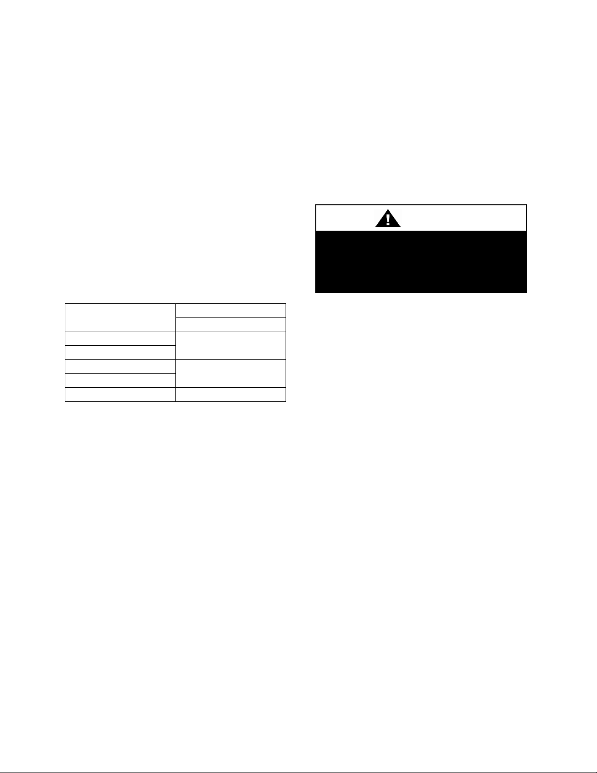
Attention should be paid to the following statements:
NOTE - Notes are intended to clarify the unit installation, operation and maintenance.
CAUTION - Caution statements are given to prevent actions that may result in
equipment damage, property damage, or personal injury.
WARNING - Warning statements are given to prevent actions that could result in
equipment damage, property damage, personal injury or death.
DANGER - Danger statements are given to prevent actions that will result in equipment
damage, property damage, severe personal injury or death.
ELECTRIC SHOCK, FIRE OR
Failure to follow safety warnings
exactly could result in dangerous
operation, serious injury, death or
Improper servicing could result in
dangerous operation, serious injury,
Before servicing, disconnect all
electrical power to the unit. More
than one disconnect may be
When servicing controls, label all
wires prior to disconnecting.
Verify proper operation after
servicing. Secure all doors with
key-lock or nut and bolt.
Improper installation, adjustment,
alteration, service or maintenance
can cause property damage,
personal injury or loss of life. Startup
and service must be performed by a
A copy of this IOM should be kept
with the unit.
Do not use any phone in the
Never test for gas leaks with an
Use a gas detection soap solution
and check all gas connections
and shut off valves.
Safety
QUALIFIED INSTALLER
EXPLOSION HAZARD
property damage.
death, or property damage.
provided.
Factory Trained Service Technician.
WHAT TO DO IF YOU SMELL GAS
Do not try to turn on unit.
Shut off main gas supply.
Reconnect wires correctly.
Do not touch any electric switch.
building.
open flame.
Page 9

9
FIRE, EXPLOSION OR CARBON
Failure to replace proper controls
could result in fire, explosion or
carbon monoxide poisoning. Failure
to follow safety warnings exactly
could result in serious injury, death or
property damage. Do not store or use
gasoline or other flammable vapors
and liquids in the vicinity of this
appliance.
Electric shock hazard. Before
servicing, shut off all electrical power
to the unit, including remote
disconnects, to avoid shock hazard
or injury from rotating parts. Follow
proper Lockout-Tagout procedures.
During installation, testing, servicing,
and troubleshooting of the equipment
it may be necessary to work with live
electrical components. Only a
qualified licensed electrician or
individual properly trained in handling
live electrical components shall
Standard NFPA-70E, an OSHA
regulation requiring an Arc Flash
Boundary to be field established and
marked for identification of where
appropriate Personal Protective
Equipment (PPE) be worn, should be
followed.
All field installed wiring must be
completed by qualified personnel.
Field installed wiring must comply
with NEC/CEC, local and state
electrical code requirements. Failure
to follow code requirements could
result in serious injury or death.
Provide proper unit ground in
accordance with these code
requirements.
Do not leave VFDs unattended in
hand mode or manual bypass.
Damage to personnel or equipment
can occur if left unattended. When in
hand mode or manual bypass mode
VFDs will not respond to controls or
alarms.
Electric motor over-current protection
and overload protection may be a
function of the Variable Frequency
Drive to which the motors are wired.
Never defeat the VFD motor overload
feature. The overload ampere setting
must not exceed 115% of the electric
motors FLA rating as shown on the
motor nameplate.
MONOXIDE POISONING HAZARD
GROUNDING REQUIRED
VARIABLE FREQUENCY DRIVES
perform these tasks.
Page 10
10
To prevent injury or death lifting
equipment capacity shall exceed unit
weight by an adequate safety factor.
Always test-lift unit not more than 24
inches high to verify proper center of
gravity lift point to avoid unit damage,
injury or death.
Always use a pressure regulator,
valves and gauges to control
incoming pressures when pressure
testing a system. Excessive pressure
may cause line ruptures, equipment
damage or an explosion which may
result in injury or death.
Door compartments containing
hazardous voltage or rotating parts
are equipped with door latches to
allow locks. Door latches are shipped
with nut and bolts requiring tooled
access. If you do not replace the
shipping hardware with a pad lock
always re-install the nut & bolt after
closing the door.
Do not use oxygen, acetylene or air
in place of refrigerant and dry
nitrogen for leak testing. A violent
explosion may result causing injury or
death.
PVC (Polyvinyl Chloride) and CPVC
(Chlorinated Polyvinyl Chloride) are
vulnerable to attack by certain
chemicals. Polyolester (POE) oils
that are used in R-410A and other
refrigerant systems will cause stress
cracking of PVC or CPVC piping,
even if only present in trace amounts.
This will result in complete piping
system failure.
CAUTION
To prevent motor overheating
compressors must cycle off for a
To maintain the proper oil level
compressors must cycle on for a
The cycle rate must not exceed 6
starts per hour.
To prevent damage to the unit, do not
use acidic chemical coil cleaners. Do
not use alkaline chemical coil
cleaners with a pH value greater than
8.5, after mixing, without first using
an aluminum corrosion inhibitor in the
cleaning solution.
UNIT HANDLING
COMPRESSOR CYCLING
3 MINUTE MINIMUM OFF TIME
minimum of 3 minutes.
3 MINUTE MINIMUM ON TIME
minimum of 3 minutes.
Page 11
11
Polyolester (POE) and Polyvinylether
(PVE) oils are two types of lubricants
used with R-410A and R134a
refrigeration systems. Refer to the
compressor label for the proper
compressor lubricant type.
CAUTION
Do not clean DX refrigerant coils with
hot water or steam. The use of hot
water or steam on refrigerant coils
will cause high pressure inside the
coil tubing and damage to the coil.
Rotation must be checked on ALL
MOTORS AND COMPRESSORS of
3 phase units at startup by a qualified
service technician. Scroll
compressors are directional and can
be damaged if rotated in the wrong
direction. Compressor rotation must
be checked using suction and
discharge gauges. Fan motor rotation
should be checked for proper
operation. Alterations should only be
made at the unit power connection.
Some chemical coil cleaning
Use
these substances only in accordance
with the manufacturer’s usage
instructions. Failure to follow
instructions may result in equipment
damage, injury or death.
WARNING
compounds are caustic or toxic.
1. Startup and service must be performed
by a Factory Trained Service
Technician.
2. The unit is for outdoor use only. See
General Information section for more
information.
3. Use only with type of the gas approved
for the boiler. Refer to the boiler rating
plate.
4. Provide adequate combustion ventilation
air to the boiler.
5. Every unit has a unique equipment
nameplate with electrical, operational,
and unit clearance specifications.
Always refer to the unit nameplate for
ratings unique to the model you have
purchased.
6. READ THE ENTIRE INSTALLATION,
OPERATION AND MAINTENANCE
MANUAL. OTHER IMPORTANT
SAFETY PRECAUTIONS ARE
PROVIDED THROUGHOUT THIS
MANUAL.
7. Keep this manual and all literature
safeguarded near or on the unit.
Page 12

Model Options
:
Unit Feature Options
GEN
MJREV SIZE SERIES MNREV VLT A1
A2
A3
A4
A5 B1
B2
B3
B4 1 2
3A
3B
3C
3D 4A
4B
4C
4D 5A
5B
5C
5D 6 7
8A
8B
8C
LZ A -
140
- C - 0 - 3 - F A C 0
E
-
0 0 0 0 : E 0 - 0 0 0 0 - 0 0 0 0 - 0 0 0 0 - 0 0 - 0 0 0
0 - 0 E 0 0 - 0 0 C 0 0 - 0 J 0 0 0 - 0 0 0 0 0 - 0 0 0 0 0 0 - 0 0 0 0 0 - 0 0 D
B
9
10A
10B
10C
10D
11
12
13
14
15 16
17
18
19
20 21
22
23
24
25
26A
26B
26C
26D
26E
26F
27
28
29
30
31 32
33
34
35
12
Air-Cooled
Evaporative-Cooled
045 = 45 ton Capacity
053 = 53 ton Capacity
055 = 55 ton Capacity
061 = 61 ton Capacity
060 = 60 ton Capacity
069 = 69 ton Capacity
075 = 75 ton Capacity
078 = 78 ton Capacity
090 = 90 ton Capacity
090 = 90 ton Capacity
095 = 95 ton Capacity
106 = 106 ton Capacity
105 = 105 ton Capacity
120 = 120 ton Capacity
120 = 120 ton Capacity
121 = 121 ton Capacity
140 = 140 ton Capacity
134 = 134 ton Capacity
170 = 170 ton Capacity
150 = 150 ton Capacity
181 = 181 ton Capacity
161 = 161 ton Capacity
200 = 200 ton Capacity
180 = 180 ton Capacity
181 = 181 ton Capacity
193 = 193 ton Capacity
239 = 239 ton Capacity
240 = 240 ton Capacity
274 = 274 ton Capacity
300 = 300 ton Capacity
356 = 356 ton Capacity
360 = 360 ton Capacity
401 = 401 ton Capacity
441 = 441 ton Capacity
450 = 450 ton Capacity
478 = 478 ton Capacity
540 = 540 ton Capacity
Air-Cooled
A = 45-60 ton units
B = 75 ton unit
C = 95-140 ton units
D = 175-200 ton units
Evaporative-Cooled
A = 53-69 ton units
B = 78 ton unit
C = 106-161 ton units
D = 193-239 ton units
E = 274-319 ton units
F = 356-401 ton units
G = 441-478 ton units
Air-Cooled
H = 90-120 ton units
K = 181 ton unit
Evaporative-Cooled
H = 90-120 ton units
J = 150-180 ton units
K = 181 ton unit
L = 240 ton unit
M = 300-360 ton units
N = 450-540 ton units
LZ Series Feature String Nomenclature
MODEL OPTIONS
Series and Generation
LZ
Major Revision
A
Unit Size
Series - Scroll Compressor
LZ Series Feature String Nomenclature
Series - Turbocor Compressor
Minor Revision
0
Voltage
2 = 230V/3Φ/60Hz
3 = 460V/3Φ/60Hz
4 = 575V/3Φ/60Hz
8 = 208V/3Φ/60Hz
A1: Compressor Style
F = R-410A Tandem VFD Compatible Scroll
Compressor
H = R-134a Turbocor Centrifugal Compressor
J = R-134a Turbocor Centrifugal Compressor with
Economizer
A2: Condenser Style
A = Air-Cooled Microchannel Condenser
H = Evaporative-Cooled Condenser
A3: Evaporator Configuration
A = Brazed Plate
B = Oversized Brazed Plate
C = Shell & Tube
D = Oversized Shell & Tube
A4: Coating
0 = Standard
E = Polymer E-Coated Condenser Coil
A5: Staging
0 = Staged On/Off Compressors
E = All Circuits Variable Capacity Compressors
G = Half Circuits Variable Capacity Compressors
Page 13

LZ Series Feature String Nomenclature
Model Options
:
Unit Feature Options
GEN
MJREV SIZE SERIES MNREV VLT A1
A2
A3
A4
A5 B1
B2
B3
B4 1 2
3A
3B
3C
3D 4A
4B
4C
4D 5A
5B
5C
5D 6 7
8A
8B
8C
LZ A -
140
- C - 0 - 3 - F A C 0
E
-
0 0 0 0 : E 0 - 0
0
0 0 - 0 0 0 0 - 0 0 0 0 - 0 0 - 0 0 0
0 - 0 E 0 0 - 0 0 C 0 0 - 0 J 0 0 0 - 0 0 0 0 0 - 0 0 0 0 0 0 - 0 0 0 0 0 - 0 0 D
B
9
10A
10B
10C
10D
11
12
13
14
15 16
17
18
19
20 21
22
23
24
25
26A
26B
26C
26D
26E
26F
27
28
29
30
31 32
33
34
35
13
B1: Type
0 = No Boilers
B2: Boiler Quantity
0 = No Boilers
B3: Type and Pipe Size
0 = No Boilers
B4: Boiler Capacity
0 = No Boilers
UNIT FEATURE OPTIONS
1: Unit Orientation
E = Walk-in Vestibule Left Access Left Water
Connections
F = Walk-in Vestibule Left Access Right Water
Connections
G = Walk-in Vestibule Left Access Bottom Water
Connections
J = Walk-in Vestibule Right Access Left Water
Connections
K = Walk-in Vestibule Right Access Right Water
Connections
L = Walk-in Vestibule Right Access Bottom Water
Connections
2: Pumping Style
0 = No Pumps
A = Const. Primary Pumping System Small Pipe Size
B = Const. Primary Pumping System Large Pipe Size
C = Var. Primary Pumping System Small Pipe Size
D = Var. Primary Pumping System Large Pipe Size
E = Primary/Secondary Pumping System Small Pipe
Size
F = Primary/Secondary Pumping System Large Pipe
Size
3A: Building Pump Configuration
0 = No Building Pumps
A = 1 Pump + High Eff Motor
B = 1 Dual Pump + High Eff Motors
C = 2 Single Pumps + High Eff Motors
D = 1 Pump + VFD + High Eff Motor
E = 1 Dual Pump + 2 VFD's + High Eff Motors
F = 2 Single Pumps + 2 VFD’s + High Eff Motors
K = 1 Pump + Field Installed VFD + High Eff Motor
L = 1 Dual Pump + 2 Field Installed VFD's + High
Eff Motors
M = 2 Single Pumps + 2 Field Installed VFD’s +
High Eff Motors
3B: Building Pump Series and RPM
0 = No Building Pumps
A = 4360 (1,200 nominal rpm)
B = 4360 (1,800 nominal rpm)
C = 4360 (3,600 nominal rpm)
D = 4380 (1,200 nominal rpm)
E = 4380 (1,800 nominal rpm)
F = 4380 (3,600 nominal rpm)
G = 4300 (1,200 nominal rpm)
H = 4300 (1,800 nominal rpm)
J = 4300 (3,600 nominal rpm)
K = 4382 (1,200 nominal rpm)
L = 4382 (1,800 nominal rpm)
M = 4382 (3,600 nominal rpm)
N = 4302 (1,200 nominal rpm)
P = 4302 (1,800 nominal rpm)
Q = 4302 (3,600 nominal rpm)
Page 14

LZ Series Feature String Nomenclature
Model Options
:
Unit Feature Options
GEN
MJREV SIZE SERIES MNREV VLT A1
A2
A3
A4
A5 B1
B2
B3
B4 1 2
3A
3B
3C
3D 4A
4B
4C
4D 5A
5B
5C
5D 6 7
8A
8B
8C
LZ A -
140
- C - 0 - 3 - F A C 0
E - 0 0 0 0 : E 0 - 0
0
0 0 - 0 0
0 0 - 0 0 0 0 - 0 0 - 0 0
0
0 - 0 E 0 0 - 0 0 C 0 0 - 0 J 0 0 0 - 0 0 0 0 0 - 0 0 0 0 0 0 - 0 0 0 0 0 - 0 0 D
B
9
10A
10B
10C
10D
11
12
13
14
15 16
17
18
19
20 21
22
23
24
25
26A
26B
26C
26D
26E
26F
27
28
29
30
31 32
33
34
35
14
3C: Pump Size
0 = No Building Pumps
A = 1.5B
B = 2B
C = 2D
D = 3D
E = 1.5x1.5x6
F = 2x2x6
G = 3x3x6
H = 4x4x6
J = 6x6x6
K = 1.5x1.5x8
L = 2x2x8
M = 3x3x8
N = 4x4x8
P = 5x5x8
Q = 6x6x8
R = 8x8x8
S = 2x2x10
T = 3x3x10
U = 4x4x10
V = 6x6x10
W = 8x8x10
Y = 4x4x11.5
Z = 5x5x11.5
1 = 6x6x11.5
2 = 8x8x11.5
3 = 4x4x13
4 = 6x6x13
5 = 8x8x13
3D: Building Pump Motor Size
0 = No Building Pumps
A = 0.5 hp
B = 0.75 hp
C = 1 hp
D = 1.5 hp
E = 2 hp
F = 3 hp
G = 5 hp
H = 7.5 hp
J = 10 hp
K = 15 hp
L = 20 hp
M = 25 hp
N = 30 hp
P = 40 hp
Q = 50 hp
R = 60 hp
S = 75 hp
4A: Recirculating Pump Configuration
0 = No Recirculating Pumps
A = 1 Pump + High Eff Motor
B = 1 Dual Pump + High Eff Motors
C = 2 Single Pumps + High Eff Motors
4B: Recirculation Pump Series & RPM
0 = No Recirculating Pumps
A = 4360 (1,200 nominal rpm)
B = 4360 (1,800 nominal rpm)
C = 4360 (3,600 nominal rpm)
D = 4380 (1,200 nominal rpm)
E = 4380 (1,800 nominal rpm)
F = 4380 (3,600 nominal rpm)
G = 4300 (1,200 nominal rpm)
H = 4300 (1,800 nominal rpm)
J = 4300 (3,600 nominal rpm)
K = 4382 (1,200 nominal rpm)
L = 4382 (1,800 nominal rpm)
M = 4382 (3,600 nominal rpm)
N = 4302 (1,200 nominal rpm)
P = 4302 (1,800 nominal rpm)
Q = 4302 (3,600 nominal rpm)
Page 15

LZ Series Feature String Nomenclature
Model Options
:
Unit Feature Options
GEN
MJREV SIZE SERIES MNREV VLT A1
A2
A3
A4
A5 B1
B2
B3
B4 1 2
3A
3B
3C
3D 4A
4B
4C
4D 5A
5B
5C
5D 6 7
8A
8B
8C
LZ A -
140
- C - 0 - 3 - F A C 0
E - 0 0 0 0 : E 0 - 0 0 0 0 - 0 0
0 0 - 0 0 0 0 - 0 0 - 0 0
0
0 - 0 E 0 0 - 0 0 C 0 0 - 0 J 0 0 0 - 0 0 0 0 0 - 0 0 0 0 0 0 - 0 0 0 0 0 - 0 0 D
B
9
10A
10B
10C
10D
11
12
13
14
15 16
17
18
19
20 21
22
23
24
25
26A
26B
26C
26D
26E
26F
27
28
29
30
31 32
33
34
35
15
4C: Recirculating Pump Size
0 = No Recirculating Pumps
A = 1.5B
B = 2B
C = 2D
D = 3D
E = 1.5x1.5x6
F = 2x2x6
G = 3x3x6
H = 4x4x6
J = 6x6x6
K = 1.5x1.5x8
L = 2x2x8
M = 3x3x8
N = 4x4x8
P = 5x5x8
Q = 6x6x8
R = 8x8x8
S = 2x2x10
T = 3x3x10
U = 4x4x10
V = 6x6x10
W = 8x8x10
Y = 4x4x11.5
Z = 5x5x11.5
1 = 6x6x11.5
2 = 8x8x11.5
3 = 4x4x13
4 = 6x6x13
5 = 8x8x13
4D: Recirculating Pump Motor Size
0 = No Recirculating Pumps
A = 0.5 hp
B = 0.75 hp
C = 1 hp
D = 1.5 hp
E = 2 hp
F = 3 hp
G = 5 hp
H = 7.5 hp
J = 10 hp
K = 15 hp
L = 20 hp
M = 25 hp
N = 30 hp
P = 40 hp
Q = 50 hp
R = 60 hp
S = 75 hp
5A: Boiler Building Pump Configuration
0 = No Boiler Pumps
5B: Boiler Building Pump Series & RPM
0 = No Boiler Pumps
5C: Boiler Building Pump Size
0 = No Boiler Pumps
5D: Boiler Building Pump Motor Size
0 = No Boiler Pumps
6: Refrigeration Options
0 = None
A = Hot gas bypass on non-variable capacity
compressor circuits
B = Hot gas bypass on all circuits
7: Refrigeration Accessories
0 = Standard
A = Sight Glass
B = Compressor Isolation Valves
C = Option A + B
8A: Unit Disconnect Type
0 = Standard Single Point Power Block
A = Single Point Power Non-fused Disconnect
8B: Disconnect 1 Size
0 = Power Block
N = 100 amps
R = 150 amps
U = 225 amps
Z = 400 amps
3 = 600 amps
5 = 800 amps
7 = 1200 amps
Page 16

LZ Series Feature String Nomenclature
Model Options
:
Unit Feature Options
GEN
MJREV SIZE SERIES MNREV VLT A1
A2
A3
A4
A5 B1
B2
B3
B4 1 2
3A
3B
3C
3D 4A
4B
4C
4D 5A
5B
5C
5D 6 7
8A
8B
8C
LZ A -
140
- C - 0 - 3 - F A C 0
E - 0 0 0 0 : E 0 - 0 0 0 0 - 0 0 0 0 - 0 0 0 0 - 0 0 - 0
0
0
0 - 0 E 0 0 - 0 0 C 0 0 - 0 J
0 0 0 - 0 0 0 0 0 - 0 0 0 0 0 0 - 0 0 0 0 0 - 0 0 D B
9
10A
10B
10C
10D
11
12
13
14
15 16
17
18
19
20 21
22
23
24
25
26A
26B
26C
26D
26E
26F
27
28
29
30
31 32
33
34
35
16
8C: Blank
0 = Standard
9: Accessories
0 = None
B = Phase & Brown Out Protection
10A: Unit Control Sequence
0 = Standard AAON Controls
10B: Unit Control Supplier
E = MCS Controls
10C: Control Supplier Options
0 = None
A = Touchscreen Computer Interface
C = Modem
G = Option A + C
10D: BMS Connection & Diagnostics
0 = None
A = BACnet IP
B = BACnet MSTP
C = Modbus IP
D = Modbus RTU
E = LonTalk
H = No BMS Connection with Diagnostics
J = BACnet IP with Diagnostics
K = BACnet MSTP with Diagnostics
L = Modbus IP with Diagnostics
M = Modbus RTU with Diagnostics
N = LonTalk with Diagnostics
11: Cabinet Options
0 = None
B = Access Door Windows
12: Vestibule Accessories
0 = None
A = Refrigerant Leak Detector
B = Motorized Service Vestibule Fresh Air
C = Vestibule Heating (Electric)
D = Vestibule Cooling (Fan/Coil)
F = Option A + B
G = Option A + C
H = Option A + D
K = Option B + C
L = Option B + D
N = Option C + D
R = Option A + B + C
S = Option A + B + D
U = Option A + C + D
Y = Option B + C + D
3 = Option A + B + C + D
13: Maintenance Accessories
0 = None
A = 115VAC Convenience Outlet Factory Wired
B = 115VAC Convenience Outlet Field Wired
C = Service Lights
F = Option A + C
J = Option B + C
14: Option Boxes
0 = None
A = 2 ft Option Box
B = 4 ft Option Box
C = 6 ft Option Box
D = 8 ft Option Box
F = 10 ft Option Box
G = 12 ft Option Box
15: Code Options
0 = Standard ETL U.S.A. Listing
A = Chicago Code
B = ETL U.S.A. + Canada Listing
16: Shipping Splits
0 = One Piece Unit
A = Two Piece Unit
17: Air-Cooled Condenser Accessories
0 = None (No Air-Cooled Condenser)
H = Cond Coil Guards + 3Φ Condenser Fan Motor +
Fan Cycling (25°F)
J = Cond Coil Guards + 3Φ Condenser Fan Motor +
VFD Condenser Fan Head Pressure Control (0°F)
Page 17

LZ Series Feature String Nomenclature
Model Options
:
Unit Feature Options
GEN
MJREV SIZE SERIES MNREV VLT A1
A2
A3
A4
A5 B1
B2
B3
B4 1 2
3A
3B
3C
3D 4A
4B
4C
4D 5A
5B
5C
5D 6 7
8A
8B
8C
LZ A -
140
- C - 0 - 3 - F A C 0
E - 0 0 0 0 : E 0 - 0 0 0 0 - 0 0
0 0 - 0 0 0 0 - 0 0 - 0 0
0
0 - 0 E 0 0 - 0 0 C 0 0 - 0 J 0 0 0 - 0 0 0 0 0 - 0 0 0 0 0 0 - 0 0 0 0 0 - 0 0 D
B
9
10A
10B
10C
10D
11
12
13
14
15 16
17
18
19
20 21
22
23
24
25
26A
26B
26C
26D
26E
26F
27
28
29
30
31 32
33
34
35
17
18: Evaporative-Cooled Condenser Accessories
0 = None (No Evaporative-Condenser)
A = No Sump Heat
B = Sump Heaters
19: Blank
0 = None
20: Blank
0 = None
21: Chiller Compression Tank
0 = None
A = AX-15V
B = AX-20V
C = AX-40V
D = AX-60V
E = AX-80V
F = AX-100V
G = AX-120V
H = AX-180V
J = AX-200V
K = AX-240V
L = AX-260V
M = AX-280V
22: Boiler Compression Tank
0 = None
23: Blank
0 = Standard
24: Chiller Accessories 1
0 = None
A = Glycol chiller
B = Air Separator
C = Thermometers & Pressure Gauges
D = Chemical Pot Feeder
E = Auto Glycol Feeder
F = Option A + B
G = Option A + C
H = Option A + D
J = Option A + E
K = Option B + C
L = Option B + D
M = Option B + E
N = Option C + D
P = Option C + E
Q = Option D + E
R = Option A + B + C
S = Option A + B + D
T = Option A + B + E
U = Option A + C + D
V = Option A + C + E
W = Option A + D + E
Y = Option B + C + D
Z = Option B + C + E
1 = Option B + D + E
2 = Option C + D + E
3 = Option A + B + C + D
4 = Option A + B + C + E
5 = Option A + B + D + E
6 = Option A + C + D + E
7 = Option B + C + D + E
8 = Option A + B + C + D + E
25: Blank
0 = Standard
26A: Blank
0 = Standard
26B: Blank
0 = Standard
26C: Blank
0 = Standard
26D: Blank
0 = Standard
26E: Blank
0 = Standard
26F: Blank
0 = Standard
27: Blank
0 = Standard
Page 18

LZ Series Feature String Nomenclature
Model Options
:
Unit Feature Options
GEN
MJREV SIZE SERIES MNREV VLT A1
A2
A3
A4
A5 B1
B2
B3
B4 1 2
3A
3B
3C
3D 4A
4B
4C
4D 5A
5B
5C
5D 6 7
8A
8B
8C
LZ A -
140
- C - 0 - 3 - F A C 0
E - 0 0 0 0 : E 0 - 0 0 0 0 - 0 0 0 0 - 0 0 0 0 - 0 0 - 0 0 0
0 - 0 E 0 0 - 0 0 C 0 0 - 0 J 0 0 0 - 0 0 0 0 0 - 0 0 0 0 0 0 - 0
0 0 0 0 - 0 0 D B
9
10A
10B
10C
10D
11
12
13
14
15 16
17
18
19
20 21
22
23
24
25
26A
26B
26C
26D
26E
26F
27
28
29
30
31 32
33
34
35
18
28: Blank
0 = Standard
29: Blank
0 = Standard
30: Blank
0 = Standard
31: Blank
0 = Standard
32: Blank
0 = Standard
33: Warranty
0 = Standard Warranty
D = Compressor Warranty Years 2-5
34: Cabinet Material
D = Galvanized Cabinet 6” Base Rail + Double Slope
Roof
H = Galvanized Cabinet 8” Base Rail + Double Slope
Roof
35: Paint & Special Pricing Authorizations
B = Premium AAON Gray Paint Exterior
E = Premium AAON Gray Paint Exterior + Shrink
Wrap
X = Special Pricing Authorization + Premium AAON
Gray Paint Exterior
1 = Option X + Shrink Wrap
4 = Special Pricing Authorization + Special Exterior
Paint Color
7 = Option 4 + Shrink Wrap
Page 19
19
Improper installation, adjustment,
alteration, service or maintenance
can cause property damage,
personal injury or loss of life. Startup
and service must be performed by a
Electrical raceways are located in the
upper wall sections of the unit. DO
NOT CUT OR DRILL into the wall
sections of the unit that are within 12
inches of the roofline.
The Clean Air Act of 1990 bans the
intentional venting of refrigerant as of
July 1, 1992. Approved methods of
recovery, recycling, or reclaiming
Coils and sheet metal surfaces
present sharp edges and care must
be taken when working with
equipment.
Failure to observe the following
instructions will result in premature
failure of your system and possible
voiding of the warranty.
General Information
AAON LZ Series chiller outdoor
mechanical rooms are complete selfcontained liquid chilling units. They are
assembled, wired, charged, and run-tested.
Models are available for air-cooled and
evaporative-cooled applications. Chiller
primary pumping packages,
primary/secondary pumping packages, and
boilers with pumping package are available
as optional features.
Factory Trained Service Technician.
Installation of LZ Series units must conform
to the ICC standards of the International
Mechanical Code, the International Building
Code, and local building, plumbing and
waste water codes. All appliances must be
electrically grounded in accordance with
local codes, or in the absence of local codes,
the current National Electric Code,
ANSI/NFPA 70 or the current Canadian
Electrical Code CSA C22.1.
must be followed.
RISK OF ELECTRICAL SHOCK
Codes and Ordinances
LZ Series units have been tested and
certified, by TL, in accordance with UL
Safety Standard 1995/CSA C22.2 No. 236.
System should be sized in accordance with
the American Society of Heating,
Refrigeration and Air Conditioning
Engineers Handbook.
Receiving Unit
When received, the unit should be checked
for damage that might have occurred in
transit. If damage is found it should be noted
on the carrier’s Freight Bill. A request for
inspection by carrier’s agent should be made
in writing at once. Nameplate should be
checked to ensure the correct model sizes
Page 20
20
To prevent motor overheating
compressors must cycle off for a
To maintain the proper oil level
compressors must cycle on for a
The cycle rate must not exceed 6
starts per hour.
Before unit operation, the main power
switch must be turned on for at least
24 hours for units equipped with
crankcase heaters.
Rotation must be checked on all
MOTORS AND COMPRESSORS of
three phase units. All motors, to
include and not be limited to pump
motors and condenser fan motors,
should all be checked by a qualified
service technician at startup and any
wiring alteration should only be made
at the unit power connection.
Scroll compressors are directional
and will be damaged by operation in
the wrong direction. High pressure
switches on compressors have been
disconnected after factory testing.
Rotation should be checked by a
qualified service technician at startup
using suction and discharge pressure
gauges and any wiring alteration
should be made at the unit power
connection.
and voltages have been received to match
the job requirements.
Storage
If installation will not occur immediately
following delivery, store equipment in a dry
protected area away from construction
traffic and in the proper orientation as
marked on the packaging with all internal
packaging in place. Leave all internal
packaging in place and secure all looseshipped items.
Outdoor Mechanical Room
COMPRESSOR CYCLING
3 MINUTE MINIMUM OFF TIME
Never turn off the main power supply to the
unit, except for complete shutdown. When
power is cut off from the unit, any
compressors equipped with crankcase
heaters cannot prevent refrigerant migration.
This means the compressor will cool down,
and liquid refrigerant may accumulate in the
compressor. The compressor is designed to
pump refrigerant gas and damage may occur
when power is restored if liquid enters the
compressor.
minimum of 3 minutes.
3 MINUTE MINIMUM ON TIME
minimum of 3 minutes.
Failure to observe the following instructions
will result in premature failure of your
system, and possible voiding of the
warranty.
Always control the system from the building
management system, or control panel, never
at the main power supply (except for
emergency or for complete shutdown of the
system).
Page 21
21
Some units may require field wired
connections. Refer to the wiring
diagrams contained within the unit to
identify any components or controls
requiring additional wiring in the field
before placing the unit into service.
All additional field wiring should be
performed by a Factory Trained
Service Technician.
CAUTION
Scroll compressors must be on a minimum
of 3 minutes and off for a minimum of 3
minutes. The cycle rate must be no more
than 6 starts per hour.
The chiller is furnished with a flow switch
installed on the outlet of each heat
exchanger. This sensor must not be
bypassed since it provides a signal to the
unit controller that water flow is present in
the heat exchanger and the unit can operate
without the danger of freezing the liquid.
Compressor life will be seriously shortened
by reduced lubrication, and the pumping of
excessive amounts of liquid oil and
refrigerant.
Wiring Diagrams
A complete set of unit specific wiring
diagrams in both ladder and point-to-point
form are laminated in plastic and located
inside the control vestibule.
FIELD WIRED CONNECTIONS
General Maintenance
When the initial startup is made and on a
periodic schedule during operation, it is
necessary to perform routine service checks
on the performance of the chiller and boiler.
This includes reading and recording suction
pressures and checking for normal subcooling and superheat. See the evaporative-
cooled condenser and air-cooled condenser
sections in this manual for specific details.
Chiller Primary Pumping
Primary pumping uses a single pump to
move water (or glycol) through the chiller
evaporator and back to the building. This
pumping package provides a constant or
variable flow of water to the building. The
pump is activated whenever the chiller is
given a run signal.
Water enters the unit through the return
water piping, and then travels through an air
separator to remove any air that is entrapped
in the water. Following this, the water flows
through a suction guide with an integral
strainer. The end of the suction guide is
removable for strainer access. The strainer
assembly is composed of two parts, the
operational strainer and the startup strainer,
(located inside the operational strainer)
which is to be removed 24 hours after
startup.
The pump is installed after the suction
guide, and before a combination valve (FloTrex). This combination valve acts as an
isolation valve, check valve, and flow
balancing valve. The evaporator is placed
after the combination valve in the water
circuit, with a flow switch installed at its
inlet and outlet. This pressure switch closes
when the velocity is above .7 feet per
second. The closing flow switch signals the
control system to indicate flow through the
heat exchanger and allow cooling to activate
as required to maintain the setpoint. The
water exiting the chiller evaporator leaves
the unit through the water out connection.
Chiller Primary/Secondary Pumping
Primary/secondary pumping option provides
variable flow to the system. It consists of a
constant flow pump for the chiller heat
exchanger and a variable flow pump for the
Page 22

22
building. The controls package senses
differential pressure across the pump with
pressure transducers installed at the suction
and discharge, and varies the speed of the
pump using a VFD in order to maintain a
given differential pressure across the pump.
The primary/secondary pumping package is
essentially composed of two piping loops
coupled together. The primary loop has a
constant flow rate in order to keep the chiller
heat exchanger from freezing, and the
secondary, variable flow loop, provides
water to the building. The two loops are
coupled via a water line that compensates
for excess flow in either loop. As the flow in
the secondary loop decreases below the flow
in the primary loop, excess flow bypasses
the building loop and circulates through the
bypass water line. On the other hand, as the
flow in the secondary loop increases above
the flow in the primary loop, excess flow
bypasses the chiller and circulates through
the bypass water line.
The secondary pump has its own suction
guide, combination valve, and isolation
valve, similar to the primary pump, with the
addition of an air separator to remove any
air that is entrapped in the water.
Condensing Boilers
AAON LZ chillers are available with factory
installed condensing boilers. All boiler
systems will include either fixed or variable
speed building pumps. All boiler building
pumps will be supplied with a suction guide
with a strainer and triple duty valve. The
suction guide contains both an operational
strainer and a startup strainer. The startup
strainer should be removed 24 hours after
startup. The triple duty valve functions as
an isolation valve, check valve, and flow
balancing valve.
The condensing boilers will be a water tube
design or a fire tube design. In a water-tube
boiler, the water flows through tubes with
the combustion products heating from the
outside. These boilers require a constant
water flow and will be provided with a
primary pump for each heat exchanger.
Some boilers have two heat exchangers and
will have two primary pumps. The primary
pump is controlled by the boiler and will
only come on when it has a call for heat.
Water-tube boilers are provided with flow
switches, which must make before the boiler
can operate.
In fire-tube boilers water flows through a
tank, with the combustion products inside
tubes. These boilers are capable of
significant water flow turn-down and do not
require individual primary pumps. A
control valve, operate by the boiler controls,
is provided with each boiler. A water flow
switch is not required with fire-tube boilers.
A low-level cutoff switch is used which will
prevent the boiler from operating when there
is not a sufficient water level present. Upon
initial startup, the boiler may have to be
cycled several times to generate an adequate
water level.
Makeup Water
A city make up water connection is provided
to replace water that is lost from the system.
Glycol units require a glycol feeder
(optional factory installed or field installed)
to replace fluid that is lost in the system.
Water should not be directly added to glycol
applications as this would dilute the glycol
concentration and thereby increase the
freezing temperature of the fluid.
The makeup water connection is provided
with a backflow preventer that has isolation
valves on the inlet and outlet for service.
Page 23
23
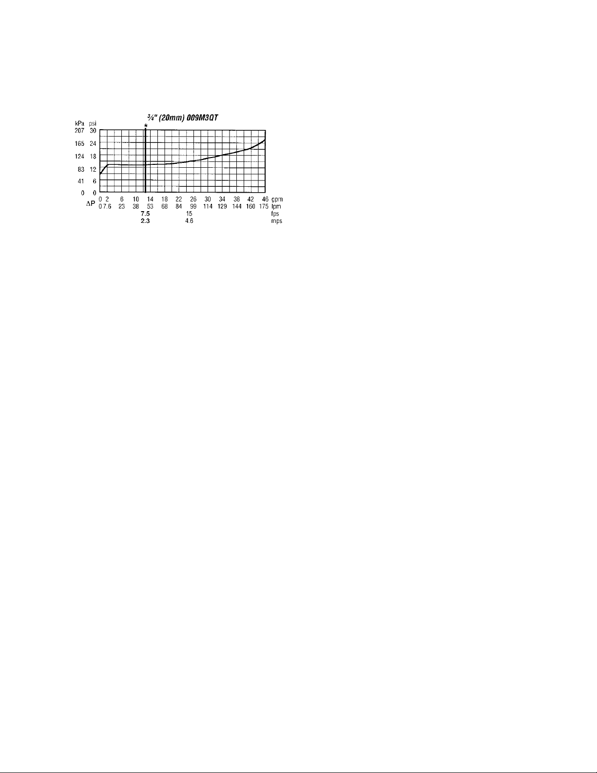
Figure 1 shows the pressure drop versus
flow rate for the backflow preventer.
Figure 1 - Backflow Preventer
There is a pressure-reducing valve after the
backflow preventer. This valve reduces the
city water pressure to maintain the operating
pressure of the system. This valve is
adjustable from 10-35 psig with a factory
setting of 30 psig. The system pressure
varies with the height of the system. The
pressure-reducing valve setting should be set
so that the pressure at the high point in the
system is high enough to vent air from the
system (usually 4 psig). There should be air
vents at all parts in the system where air
could be trapped. If the pressure is not high
enough throughout the system, flashing
could occur in the piping or the pump could
cavitate. There is an isolation valve on the
inlet and outlet of the pressure-reducing
valve for service.
The pressure reducing valve fills the system
at a reduced rate. There is a bypass around
the pressure reducing valve for the initial fill
of the system to increase the initial fill
speed. After the initial system fill, this valve
should be closed.
Compression Tank
As the water temperature in the system
increases, the volume that water displaces
increases. In order to compensate for these
expansion forces, a compression or
expansion tank must be used. The factory
installed tank option includes a pre-
pressurized diaphragm compression tank
that is preset for 12 psig.
The factory pre-charge pressure may need to
be field adjusted. The tank must be precharged to system design fill pressure before
placing into operation. Remove the pipe
plug covering the valve enclosure. Check
and adjust the charge pressure by adding or
releasing air.
If the system has been filled, the tank must
be isolated from the system and the tank
emptied before charging. This ensures that
all fluid has exited the diaphragm area and
proper charging will occur.
If the pre-charge adjustment is necessary, oil
and water free compressed air or nitrogen
gas may be used. Check the pre-charge
using an accurate pressure gauge at the
charging valve and adjust as required. Check
air valve for leakage. If evident, replace the
Schrader valve core. Do not depend on the
valve cap to seal the leak. After making sure
the air charge is correct, replace the pipe
plug over the charging valve for protection.
Purge air from system before placing tank
into operation. All models have system
water contained behind the diaphragm.
It is recommended that the pre-charge be
checked annually to ensure proper system
protection and long life for the vessel.
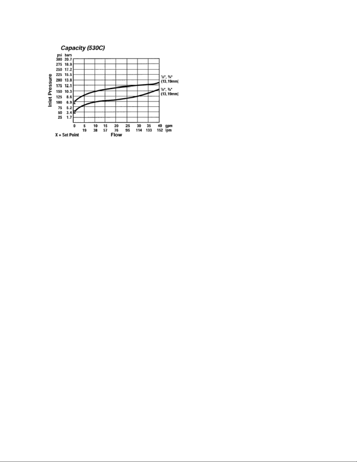
Pressure Relief Valve
Required pressure relief valve is installed in
the unit. This valve is set at 125 psig. Figure
2 shows inlet pressure versus capacity for
this pressure relief valve. See appendix for
additional information.
Page 24
24
Figure 2 - Pressure Relief Valve
Automatic Air Vent
There is an automatic air vent installed at the
high point of the system inside the pumping
package compartment. The air vent valve
must be in the proper position for operation.
Ensure that the small vent cap is loosened
two turns from the closed position, allowing
air to be vented from the system. It is
advisable to leave the cap on to prevent
impurities from entering the valve. See
appendix for additional information.
Dual Pumps
When redundant pumping is required,
factory installed dual pumps or two single
pumps can be ordered. A dual pump is a
pump with two independent motors and
impellors in a single casing. This dual pump
has a swing split-flapper valve in the
discharge port to prevent liquid recirculation
when only one pump is operating. Isolation
valves in the casing allow one pump to be
isolated and removed for service while the
other pump is still operating.
When redundant pumping is required with
high flow rates, two independent pumps
may be installed in parallel. Each pump will
have its own suction guide/strainer,
combination valve, and isolation valves.
The controls package will activate the pump
when the unit is given a run command. If the
controls do not recognize flow in 60 seconds
(factory default), the second pump will be
activated and an alarm signal will be
generated. If the second pump does not
activate, the cooling will be locked out. See
Appendix - Water Piping Component
Information for additional information.
Pressure Gauges and Thermometers
Pressure gauges and thermometers are
available as a factory installed option.
Thermometers are installed on the inlet and
outlet of the unit. One pressure gauge is
installed at each pump. This pressure gauge
is connected in three places to the water
piping before the suction guide/strainer,
after the suction guide and before the pump,
and after the pump. There is also a valve at
each of these points to isolate the pressure.
To measure the pressure at any given point,
open the valve at that point and close the
other two valves. One gauge is used so that
the calibration of the pressure gauge is
irrelevant in the calculation of the
differential pressure.
Pipe Insulation
The water piping and components on units
with pumping packages are not insulated at
the factory. Insulation should be installed on
the water piping after the system has been
checked for leaks.
Page 25
25
Location
Unit Size
45-540 tons
Left
96”
Right
Compressor End
72”
Chiller HXC End
Top
Unobstructed
All roofing work should be performed
by competent roofing contractors to
Installation
Outdoor Mechanical Room Placement
The AAON LZ Series is designed for
outdoor applications and can be mounted at
ground level or on a rooftop. It must be
placed on a level and solid foundation that
has been prepared to support its weight.
The placement relative to the building air
intakes and other structures must be
carefully selected. Be sure to observe the
dimensions that are on the rating plate of the
chiller for operational and service
clearances.
Table 1 - Service Clearances
Condenser coils and fans must be free of any
obstructions in order to start and operate
properly with a correct amount of airflow.
For proper unit operation, the immediate
area around condenser(s) must remain free
of debris that may be drawn in and obstruct
airflow in the condensing section.
Consideration must be given to obstruction
caused by snow accumulation when placing
the unit.
Curb and Steel Mount Installation
Make openings in the roof decking large
enough to allow for water piping, electrical,
and gas penetrations and workspace only.
Do not make openings larger than necessary.
Set the curb to coincide with the openings.
Make sure curb is level.
Unit specific curb drawing is included with
job submittal. See SMACNA Architectural
Sheet Metal Manual for curb installation
details.
avoid any possible leakage.
When installed at ground level, a one-piece
concrete slab should be used with footings
that extend below the frost line. Care must
also be taken to protect the coil and fins
from damage due to vandalism or other
causes.
If unit is elevated a field supplied catwalk is
recommended to allow access to unit service
doors.
This unit ships with a curb gasket that is
1¼” wide and 1½” tall. It is recommended
that this or another similar gasket be used
between the curb and the unit to reduce
vibration transmission from the unit to the
building.
Page 26
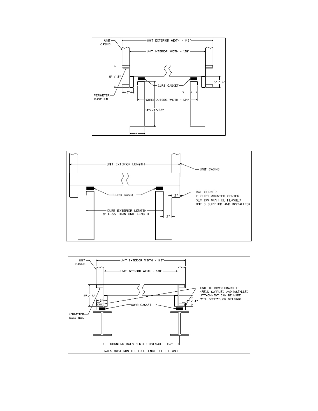
26
Figure 3 - Curb Mounting with Dimensions
Figure 4 - Curb End Detail
Figure 5 - Steel Mounting Rail with Dimensions
Page 27
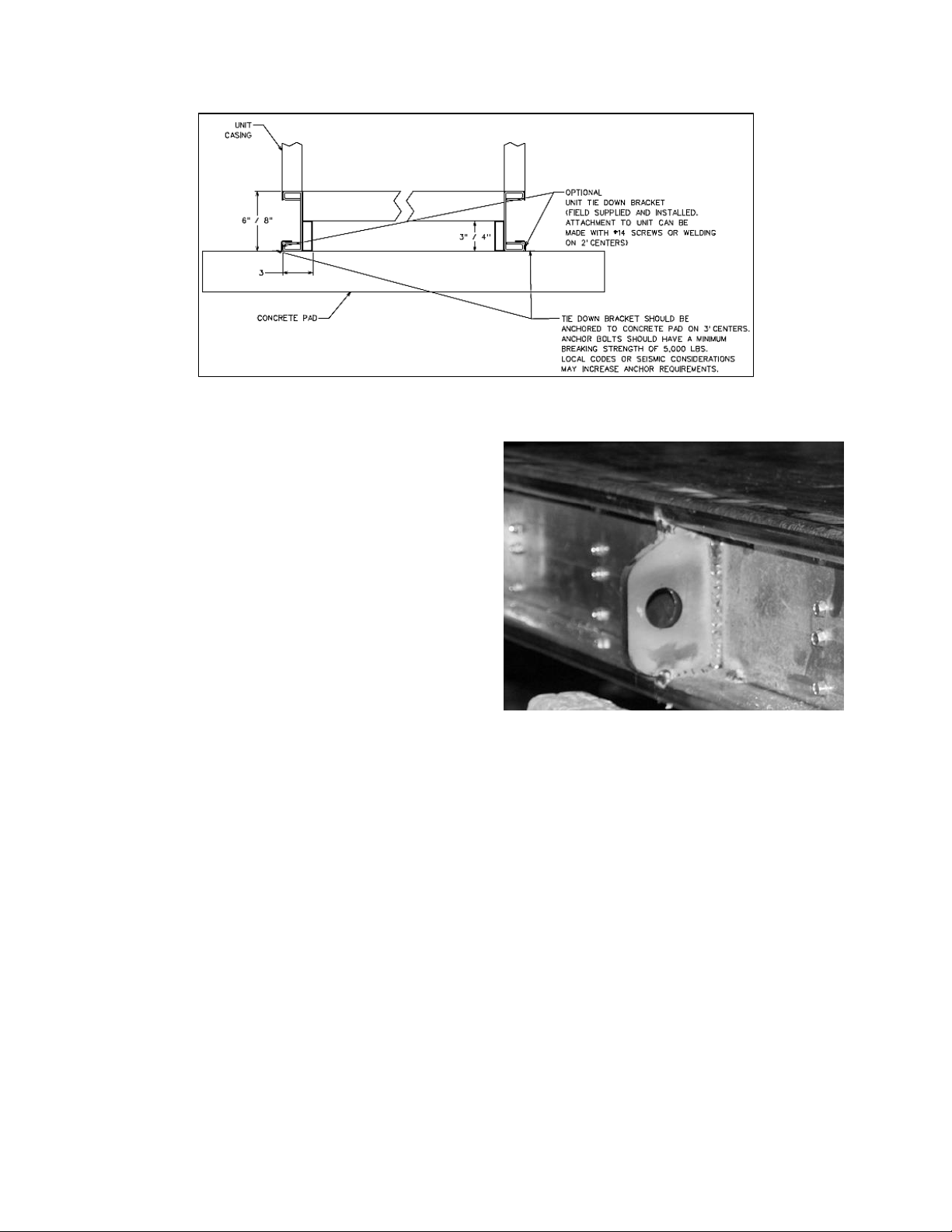
27
Figure 6 - Concrete Pad Mounting with Dimensions
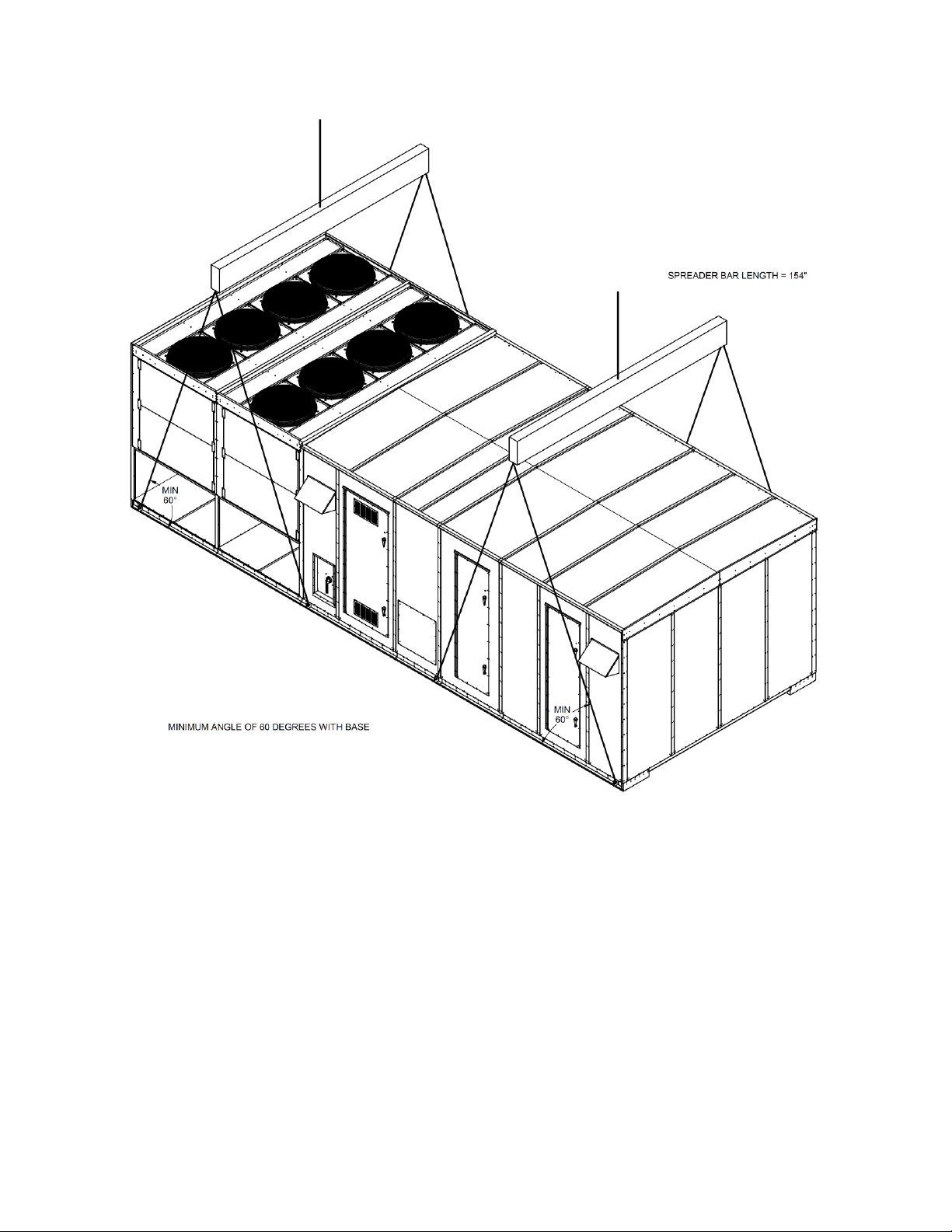
Lifting and Handling
If cables or chains are used to hoist the unit
they must be the same length and care
should be taken to prevent damage to the
cabinet. See Figure 8 for additional
information.
Before lifting unit, be sure that all shipping
material has been removed from unit. Secure
hooks and cables at all lifting points/ lugs
provided on the unit.
Hoist unit to a point directly above the curb
or mounting rail. Be sure that the gasket
material has been applied to the curb or
mounting rail.
Carefully lower and align unit with utility
openings. Lower the unit until the unit skirt
fits around the curb. Make sure the unit is
properly seated on the curb and is level.
Do not push, pull or lift the unit from
anything other than its base.
Figure 7 - Lifting Points
Page 28
28
Figure 8 - LZ Series Example Lifting Detail
Lifting slot locations are unit specific.
Unit must be rigged at all marked lifting points.
Page 29
29
The chiller must be operated only
with liquid flowing through the
evaporators.
Boilers must be operated only with
liquid flowing through the boiler.
PVC (Polyvinyl Chloride) and CPVC
(Chlorinated Polyvinyl Chloride) are
vulnerable to attack by certain
chemicals. Polyolester (POE) oils
used with R-410A and other
refrigerants, even in trace amounts,
in a PVC or CPVC piping system will
result in stress cracking of the piping
and fittings. This will result in
complete piping system failure.
Installing Contractor is responsible
for proper sealing of the water piping
and electrical entries into the unit
Failure to seal the entries may result
in damage to the unit and property.
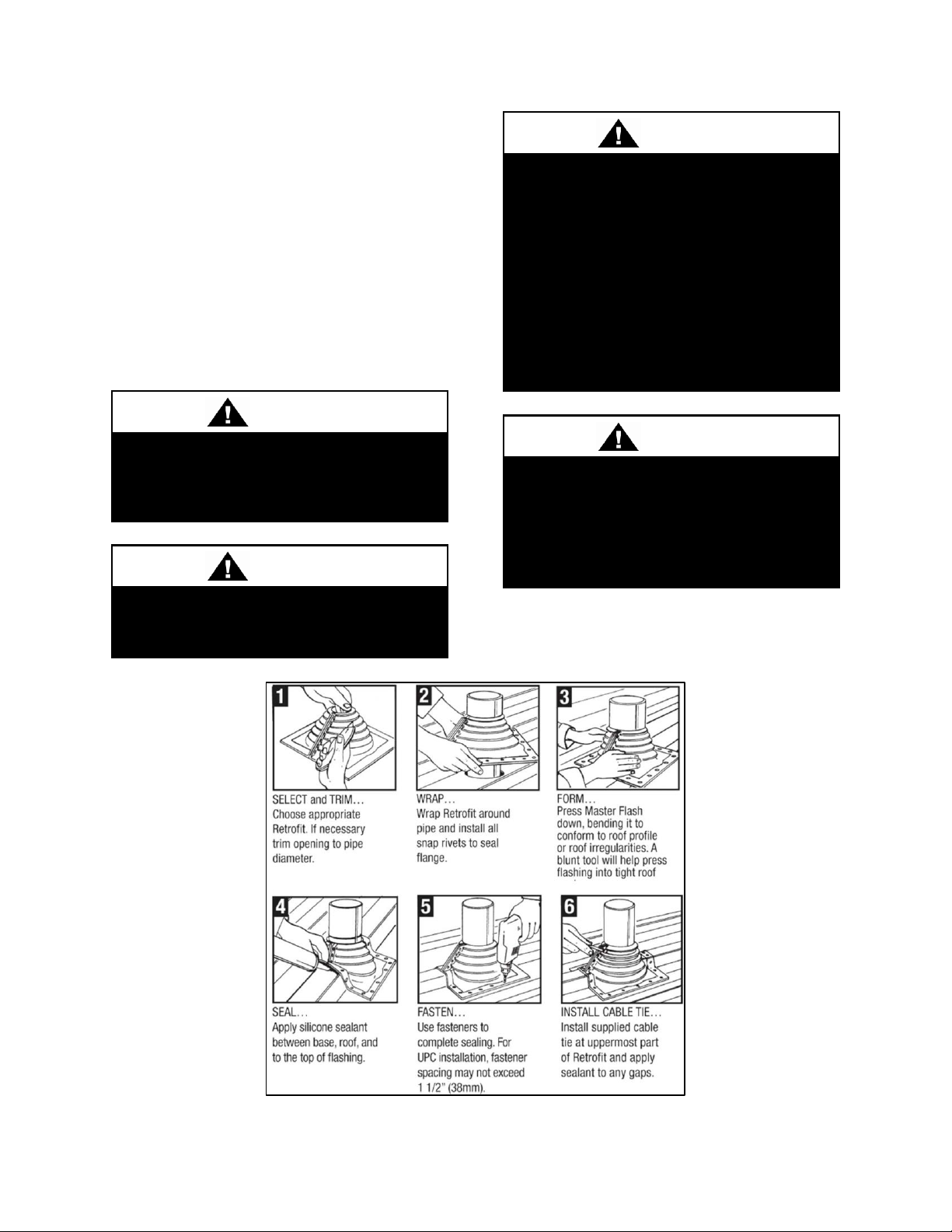
Water Connection
Remove the shipping cover from the water
connection cutout in the post. Connect the
supply and return water lines. The standard
water connection is grooved end pipe. The
connection size is listed on the unit rating
sheet along with the designed volumetric
flow rate. The maximum operating pressure
for AAON LZ Series unit is 125 psi. Install
the flashing provided by AAON according
to the steps in Figure 9. Finished water
connection will be water tight.
Figure 9 - Water Pipe Flashing Installation
Page 30
30
Failure to apply sealing compound as
detailed can result in property
damage, personal injury, or death.
DO NOT use matches, candles, open
flames, or other ignition sources to
check for gas leaks. Use only
approved leak detection methods.
Failure to comply with this warning
can result in property damage,
personal injury, or death.
Failure to provide a properly installed
vent and air system can result in
property damage, personal injury, or
death.
Boiler Gas Connection Before making gas connection, make sure the boiler is being supplied with the type of fuel shown on the boiler nameplate.
Table 2 and Table 3 show the gas
connection size and type (NPT or flanged)
provided along with the required inlet gas
pressure for the unit. Refer to feature B on
the LZ Series unit feature string to
determine which line of the table to use. For
example, a unit with feature B = A3CC will
have a 2” NPT gas connection and require
an inlet gas pressure in the range of 6-14”
W.C.
Use only pipe sealing compound that is
compatible with propane gases on all
threaded connections. Apply sparingly only
to the male threads of the pipe joints so that
the pipe sealing compound does not block
any gas flow.
Before being placed in operation, the boiler
and all gas piping connections must be
checked for leaks. The boiler must be
disconnected from the gas supply piping
system during any pressure testing of the
system at pressures in excess of .5 psig (14”
W.C.). The boiler must be isolated from the
gas supply piping system by closing the
manual shutoff valve during any pressure
testing of the system at pressures equal to or
less than .5 psig (14” W.C.).
Some leak test solutions, including soap and
water, may cause corrosion. These solutions
should be rinsed off with water after testing.
Boiler Air Intake / Vent Piping Each boiler requires the installation of air intake and vent piping. This piping has been removed for shipping purposes. All piping must be reinstalled according to the instructions provided in this section prior to boiler operation.
All boilers must be vented and supplied with
combustion and ventilation air as described
in this section and in the Lochinvar
Installation & Operation Manual included
with the boiler. Ensure the vent and air
piping and combustion air supply comply
with instructions regarding vent system, air
system, and combustion air quality.
Inspect finished vent and air intake piping
thoroughly to ensure all are airtight and
comply with the instructions provided and
with all requirements of applicable codes.
Page 31

31
Heating Feature
Boiler
Inlet Gas
Pressure
Gas Header
B1
B2
B3
B4
Size
Qty
Input
Capacity
(CFH)
Pipe
Size
Conn.
Type
A
1
C or D
A
KBN400
1
400
6-14” W.C.
1
NPT A 2
C or D
A 2 800
6-14” W.C.
1 1/2
NPT A 3
C or D
A 3 1,200
6-14” W.C.
2
NPT
A
4
C or D
A 4 1,600
6-14” W.C.
2
NPT
A
1
C or D
B
KBN501
1
500
6-14” W.C.
1 1/2
NPT A 2
C or D
B 2 1,000
6-14” W.C.
1 1/2
NPT A 3
C or D
B 3 1,500
6-14” W.C.
2
NPT A 4
C or D
B 4 2,000
6-14” W.C.
2
NPT A 1
C or D
C
KBN601
1
600
6-14” W.C.
1 1/2
NPT A 2
C or D
C 2 1,200
6-14” W.C.
2
NPT A 3
C or D
C 3 1,800
6-14” W.C.
2
NPT A 4
C or D
C 4 2,400
2-5 psi
2
NPT A 1
C or D
D
KBN701
1
700
6-14” W.C.
1 1/2
NPT A 2
C or D
D 2 1,400
6-14” W.C.
2
NPT A 3
C or D
D 3 2,100
2-5 psi
2
NPT A 4
C or D
D 4 2,800
2-5 psi
2
NPT A 1
C or D
F
KBN801
1
800
6-14” W.C.
1 1/2
NPT A 2
C or D
F 2 1,600
6-14” W.C.
2
NPT
A
3
C or D
F 3 2,400
2-5 psi
2
NPT
A
4
C or D
F 4 3,200
2-5 psi
2
NPT A 1
C or D
G
SBN1000
1
1,000
6-14” W.C.
1 1/2
NPT A 2
C or D
G 2 2,000
2-5 psi
2
NPT A 3
C or D
G 3 3,000
2-5 psi
2
NPT A 4
C or D
G 4 4,000
2-5 psi
2
NPT A 1
C or D
H
SBN1300
1
1,300
6-14” W.C.
2
NPT A 2
C or D
H 2 2,600
2-5 psi
2
NPT A 3
C or D
H 3 3,900
2-5 psi
2
NPT A 4
C or D
H 4 5,400
2-5 psi
2
NPT A 1
C or D
J
SBN1500
1
1,500
6-14” W.C.
2
NPT A 2
C or D
J 2 3,000
2-5 psi
2
NPT A 3
C or D
J 3 4,500
2-5 psi
2
NPT A 4
C or D
J 4 6,000
2-5 psi
2
NPT
Table 2 - Unit Gas Pipe Information, Feature B4 = A-J
Page 32

32
Heating Feature
Boiler
Inlet Gas
Pressure
Gas Header
B1
B2
B3
B4
Size
Qty
Input
Capacity
(CFH)
Pipe
Size
Conn.
Type
A
1
C or D
K
FBN2000
1
2,000
2-5 psi
1 1/2
NPT A 2
C or D
K 2 4,000
2-5 psi
2
NPT A 3
C or D
K 3 6,000
2-5 psi
2
NPT
A
4
C or D
K 4 8,000
2-5 psi
3
Flange
A
1
C or D
L
FBN2500
1
2,500
2-5 psi
1 1/2
NPT A 2
C or D
L 2 5,000
2-5 psi
2
NPT A 3
C or D
L 3 7,500
2-5 psi
3
Flange
A
4
C or D
L 4 10,000
2-5 psi
3
Flange
A
1
C or D
M
FBN3000
1
3,000
2-5 psi
1 1/2
NPT A 2
C or D
M 2 6,000
2-5 psi
2
NPT A 3
C or D
M 3 9,000
2-5 psi
3
Flange
A
4
C or D
M 4 12,000
2-5 psi
3
Flange
A
1
C or D
N
FBN3500
1
3,500
2-5 psi
2
NPT A 2
C or D
N 2 7,000
2-5 psi
3
Flange
A
3
C or D
N 3 10,500
2-5 psi
3
Flange
A
4
C or D
N 4 14,000
2-5 psi
3
Flange
Use only primer and cement
approved for use with PVC
(ANSI/ASTM D2564).
Table 3 - Unit Gas Pipe Information, Feature B4 = K-N
Sidewall Direct Boiler Venting
For units with Lochinvar Knight XL and
SYNC boilers (feature B4 = A, B, C, D, E,
F, G, H, or K), the air intake and vent piping
runs from each boiler through the sidewall
of the unit into the supplied sidewall vent
termination.
1. On the sidewall above the boiler access
door, remove the shipping cover and attach
the sidewall vent plate shipped with the unit.
Figure 11 - Sidewall Vent Plate Installation
2. Attach air intake piping to the air inlet
connector on the boiler at one end and run
through the sidewall of the unit at the other
end. All air intake pipes and fittings are
PVC.
Figure 10 - Sidewall Vent Shipping Cover
Removal
Page 33

33
Figure 12 - Typical Air Intake Piping
Figure 13 - Typical Flue Vent Piping
Page 34

34
Use only primer and cement
approved for use with CPVC
(ANSI/ASTM F493).
3. Attach vent piping to the flue pipe adapter
on the boiler at one end and run through the
sidewall of the unit at the other end. All
Vent pipes and fittings are CPVC. Vent
piping must be pitched at a minimum of 1/4
inch per foot back to the boiler.
4. Install the vent and air intake piping
through the wall into the sidewall vent base.
Use RTV silicone sealant to seal the air
intake pipe. Mount and secure the sidewall
vent base using stainless steel screws. Seal
all gaps between the pipes and the sidewall.
Seal around the sidewall vent base to the
wall ensuring no air gaps.
5. Assemble vent cap to vent base and
securely attach using stainless steel screws.
Figure 15 - Sidewall Vent Cap
Vertical Direct Boiler Venting
For units with Lochinvar Crest boilers
(feature B4 = K, L, M, or N), the air intake
and vent piping is installed to run vertically
through the roof of the unit.
1. Remove shipping covers from openings in
the roof.
Figure 14 - Sidewall Vent Base
Figure 16 - Roof Air Intake and Vent Piping
Shipping Covers
Page 35

35
For units with PVC piping, use only
primer and cement approved for use
with PVC (ANSI/ASTM D2564).
The female end of each component
incorporates a sealing gasket and a
mechanical locking bond. Examine
all components prior to installation.
Gaskets must be in proper position to
prevent leakage.
For units with stainless steel piping,
all components must be installed in
accordance with the manufacturer’s
instructions to ensure all joints are
secure and sealed correctly.
2. Attach air intake piping to the air inlet
connector on the boiler and run vertically
through the roof of the unit. The air intake
pipes and fittings will either be all PVC or
all stainless steel components.
JOINT CONNECTIONS
Figure 17 - Typical Vertical Air Intake Piping
Page 36

36
For units with stainless steel piping,
all components must be installed in
accordance with the manufacturer’s
instructions to ensure all joints are
secure and sealed correctly.
For units with multiple boilers,
terminate all vent pipes at the same
height and all air intake pipes at the
same height to avoid recirculation of
flue products. Failure to do so may
result in property damage, personal
injury, or death.
3. Insert the male end into the female
section. Push the units together and turn
them until half of the bead on the male end
is covered by the flared edge of the female
end. This creates the needed airtight seal
for Category II, III, or IV appliances. Align
the seams on the vent lengths and orient
them upward on all horizontal applications.
4. Tighten the locking band with a nut driver
until snug, plus a quarter turn. Before
proceeding, recheck all joints end ensure
that all male sections extend to the top of the
flared female end and all clamps are
tightened.
5. Attach vent piping to the vent connector
on the boiler and run vertically through the
roof of the unit. All vent pipes and fittings
will be stainless steel components.
6. The air intake piping must terminate in a
down turned 180° return pipe no further
than 2 feet horizontally from the center of
the vent pipe. The placement avoids
recirculation of flue products into the
combustion air stream.
7. The vent piping must terminate in an up
turned coupling with the top of the coupling
or rain cap at least 36 inches above the air
intake.
Figure 18 - Correct Joint Connection
Figure 19 - Incorrect Joint Connection
Page 37

37
Figure 20 - Typical Vertical Vent Piping
Figure 21 - Vertical Termination of Air Intake and Vent Piping
Page 38

38
Boiler Condensate Drain
Each boiler is provided with a neutralizer kit
for neutralizing the condensate from the
boiler. The condensate leaving the boiler is
slightly acidic, typically with a pH of 3 to 5,
and has the potential to harm the
environment and the sewer system. The
neutralizer kit raises the pH to a more
neutral level before it is discharged to a
common condensate drain line. The
common condensate drain line has a
threaded pipe connection where it passes
through the sidewall of the unit. Connect
the drain line to an appropriate waste line
following applicable codes.
Split Unit Assembly
The larger LZ chillers may be shipped in
two pieces which will need to be lifted into
place separately then assembled into the
completed unit. The following procedure
should be used to complete the assembly.
1. The shipping covers over the open
sections of the unit should be removed
just before installation.
2. The larger section should be lifted first
and set exactly in the desired location.
3. Once this section is in place, the
provided neoprene gasket should be
placed on the entire face of the open
connection.
4. The smaller section should then be
placed as close as possible to the first
section.
5. After the crane rigging is removed,
come-alongs should be attached to the
nearest lifting lugs of both sections on
each side base rail. The two sections
should then be pulled together until the
bases are flush. If necessary the internal
braces at the connection location can be
used to align the top of the two sections.
6. When the two sections are properly
aligned, the provided splice parts should
be installed. There is one internal splice
on the base seam and external splices for
the roof and both side panels. Before
installing the side panel splices,
polyurethane caulking should be applied
to the top 6” of the panel joint starting at
the bottom of the roof lip.
7. The water pipes should then be
connected across the unit joint using the
provided pipe sections and grooved
couplings.
8. All electrical connections between the
two sections are made using NEMA
boxes inside the cabinet. These
connections must be made per the unit
wiring diagram and checked for ground
faults before power is connected to the
unit. Failure to do this could result live
power being applied to loose wires.
Unit Mounting Isolation
For roof mounted applications or anytime
vibration transmission is a factor, vibration
isolators may be used.
Access Doors
Lockable access doors are provided to the
compressor and control compartment. A
separate access door is also provided to the
evaporator and pumping package
compartment.
A light switch is provided on the wall of the
compressor and control compartment.
Low Ambient Operation
If the chiller is ordered with the low ambient
head pressure control, the liquid system
must use a glycol solution and the piping
Page 39

39
Electric shock hazard. Before
attempting to perform any installation,
service, or maintenance, shut off all
electrical power to the unit at the
disconnect switches. Unit may have
multiple power supplies. Failure to
disconnect power could result in
dangerous operation, serious injury,
must be insulated to be prepared for freezing
conditions. Care must be taken in
connecting electrical power to the heating
tape and thermostat.
The AAON low ambient head pressure
control is used to operate a refrigerant
system down to 0°F outside air temperature.
As the ambient temperature drops, the
condenser becomes more effective and
decreases the head pressure. When the head
pressure gets too low, there will be
insufficient pressure to operate the
expansion valve properly. During low
ambient temperatures, it is difficult to start a
system because the refrigerant will migrate
to the cold part of the system (condenser)
and make it difficult for refrigerant to flow.
The low ambient system maintains normal
head pressure during periods of low ambient
temperatures by controlling condenser air
flow by modulating fan speed. By reducing
condenser air flow, the condenser heat
rejection capacity is reduced. This allows
unit operation down to 0°F.
During higher ambient temperatures, the
entire condenser is required to condense
refrigerant. During these higher ambient
temperatures, full condenser air flow is
required to maintain system capacity. The
VFD controlled condenser fan low ambient
head pressure control will modulate the
condenser air flow to maintain proper head
pressure. Along with electronic expansion
valves, VFD controlled condenser fans
optimize system performance.
Electrical
The electrical power connections are made
in the electrical control compartment.
The microprocessor control furnished with
the unit is supplied with its own power
supply factory wired to the main power of
the outdoor mechanical room.
Verify the unit nameplate voltage agrees
with the power supply. Connect power and
control field wiring as shown on the unit
specific wiring diagram provided with the
unit.
Size supply conductors based on the unit
MCA rating. Supply conductors must be
rated a minimum of 167°F (75°C).
Route power and control wiring, separately,
through the utility entry. Do not run power
and signal wires in the same conduit. Power
and signal wires in the same conduit can
cause electrical interference.
Protect the branch circuit in accordance with
code requirements. The unit must be
electrically grounded in accordance with
local codes, or in the absence of local codes,
the current National Electric Code,
ANSI/NFPA 70 or the current Canadian
Electrical Code CSA C22.1.
Power wiring is to the unit terminal block or
main disconnect. All wiring beyond this
point has been done by the manufacturer and
cannot be modified without affecting the
unit's agency/safety certification.
death or property damage.
Page 40

40
Convenience outlet and service light
circuits are wired to the incoming
power side of the disconnect. These
circuits will remain powered even
when unit disconnect is off.
Installing Contractor is responsible
for proper sealing of the electrical
and gas entries into the unit. Failure
to seal the entries may result in
damage to the unit and property.
Scroll compressors are directional
and will be damaged by operation in
the wrong direction. High pressure
switches on compressors have been
disconnected after factory testing.
Rotation should be checked by a
qualified service technician at startup
using suction and discharge pressure
gauges and any wiring alteration
should only be made at the unit
power connection.
CAUTION
BURNING FOAM INSULATION IS
TOXIC! Do not cut holes into any
foam insulated panels with any flame
producing cutter such as a plasma
CONVENIENCE OUTLETS AND
SERVICE LIGHTS
Wire control signals to the unit’s low
voltage terminal block located in the
controls compartment.
Startup technician must check for proper
motor rotation for compressors, condenser
If any factory installed wiring must be
replaced, use a minimum 221°F (105°C)
type AWM insulated conductors.
fan motors, and pumps and check fan motor
amperage listed on the motor nameplate is
not exceeded. Motor overload protection
may be a function of the variable frequency
drive and must not be bypassed. Variable
frequency drives are programmed to
automatically rotate the fan in the correct
rotation. Do not rely on fan with variable
frequency drives for compressor rotation.
cutter or cutting torch.
Note: All units are factory wired for
208/230V, 460V, or 575V. If unit is to be
connected to a 208V supply, the transformer
must be rewired to 208V service.
Page 41

41
Rotation must be checked on all
MOTORS AND COMPRESSORS of
three phase units. Condenser fan
motors should all be checked by a
qualified service technician at startup
and any wiring alteration should only
be made at the unit power
connection. Variable frequency drives
are programmed to automatically
rotate the fan in the correct rotation.
Do not rely on fans with variable
frequency drives for compressor
rotation.
CAUTION
Evaporative-Cooled Condenser Field Piping
Connections
There are at least two field water
connections that must be made for the
evaporative-cooled condenser. There is a
3/4” MPTF copper fitting city make up
water connection and a 2” PVC socket drain
connection, as shown in
Figure 22. This drain should connect to a
sanitary sewer or other code permitted drain.
These connections can go through the base
or the wall of the unit.
There is a cutout in the base with a cap that
is 1” tall and the cap is sealed to the unit
base to prevent any leaks in the unit from
penetrating into the building. Any piping
through the base should go through a field
cutout in this cap. The pipes must be sealed
to the cap once the piping is complete to
prevent any leaks in the unit from
penetrating into the building.
A field cutout must be made in the wall if
the evaporative-cooled condenser piping is
to go through the unit wall. This cutout must
be sealed once the piping is installed to
prevent water from leaking into the unit.
Page 42

42
Figure 22 - Evaporative-Cooled Condenser Section Layout
Including Field Water Connections and Base Cutout
Page 43

43
Electric shock hazard. Shut off all
electrical power to the unit to avoid
shock hazard or injury from rotating
parts.
Improper installation, adjustment,
alteration, service or maintenance
can cause property damage,
personal injury or loss of life. Startup
and service must be performed by a
Startup
(See back of the manual for startup form)
Factory Trained Service Technician.
Before starting the chiller for the first time,
verify the following items have been
checked:
1. Verify that electrical power is available
and that the voltage is correct and the
capacity is equal to or greater than the
unit’s MOP listed on the nameplate. If
the chiller has an evaporative cooled
condenser, verify that the make-up water
supply is available and properly
connected.
2. Chillers selected to use standard water
are provided with a connection for city
make-up water, verify that this is
available and properly connected.
Glycol chillers may be selected with an
auto-glycol feeder. If present verify that
this has been set up correctly and filled
with the proper water-glycol mixture
(see Appendix XX). Open automatic air
vents as shown in Appendix XX.
3. Before applying power, review the MCS
Controller manual provided with the
chiller. Understand the operation of the
controller display panel as well as the
MCS Connect PC program.
4. Verify that all crankcase heaters are
operating correctly. The crankcase
heaters must be energized for at least 24
hours before starting the compressors to
clear any liquid refrigerant from the
compressors.
5. Verify that the rotation of all pumps,
motors, and compressors are correct.
The rotations have been checked at the
factory, so if any motors that are not
powered by a Variable Frequency Drive
are operating backwards two phases
should be switch at the unit power
connection.
6. Verify that any remote stop/start device
or BMS signal is connected to the chiller
controller and requesting the chiller to
start.
7. With the proper pumps running, verify
that there is liquid flow through the
chiller. This can be checked by
monitoring the status of the chiller’s
flow switch or verifying a pressure drop
using the provided pressure gauges.
8. A building load of at least 25% of the
chiller capacity should be present in
order to properly check operation.
9. Complete the general check list at the
top of the startup form to make a last
check that the chiller is ready to operate.
Use the general check list at the top of the
LZ Series Startup Form to make a last check
that all the components are in place, water
flow is present, and the power supply is
energized.
Page 44

44
Altitude
Pitch
0-2,000’ (Factory Default)
35°
2,000’-4,000’
37.5°
Over 4,000’
40°
Altitude
Pitch
0-6,000’ (Factory Default)
30°
Over 6,000’
35°
Rotation must be checked on all
MOTORS AND COMPRESSORS of
three phase units. All motors, to
include and not be limited to pump
motors and condenser fan motors,
should all be checked by a qualified
service technician at startup and any
wiring alteration should only be made
at the unit power connection.
Before completing installation, a
complete operating cycle should be
observed to verify that all
components are functioning properly.
Test the chiller operation by changing the
Run/Stop switch to “Run”, and enabling one
system at a time. The compressors should
not be placed in “Manual On” for any period
longer that what is required to check for
proper rotation. The Electronic Expansion
Valves will not function when the
compressor is operated in this mode.
Using the circuit disable switches, cycle
through all compressors to ensure they are
operating within tolerance. While
performing checks, use the startup form to
record observations of compressor amps,
refrigerant pressures and temperatures.
Pressure readings should be independently
verified using a set of calibrated gauges. If
necessary apply offsets to the unit
controller’s readings through the MCS
Controls display or through the MCS
Connect PC program.
When all compressors have been observed
to function correctly, enable all circuits and
observe the chiller until it reaches a steady
state of operation. If necessary, adjust
leaving water setpoint to match desired
target. For units with BMS communication,
verify that the BMS system can access and
modify all necessary points.
Chillers that are provided with single point
piping connections for two evaporator
barrels are equipped with balancing valves
on each heat exchanger. Flow should be
balanced between the two evaporators by a
hydronic systems balancing professional.
Note: For more information on
programming the controller refer to the
MCS Controller manual provided with the
chiller.
Condenser Fan Pitch Adjustment
Units installed at elevations above 2,000 feet
may require adjustment of the condenser fan
pitch to achieve optimal performance. See
Table 4 or Table 5 for the correct pitch
values.
Table 4 - Air-Cooled Condenser Fan Pitch
Table 5 - Evaporative-Cooled Condenser
Fan Pitch
Multi-Wing Z Series Aluminum Fan Blade
Pitch Angle Setting Instructions
1. Maintain the balance of fan
Mark the hub castings across a joint, so the
fan hub can be reassembled in the same
orientation.
Page 45

45
Bushing
Mount
A
B
Bushing
Mount
Bushing
Bushing
1
2
3
4
Mark the location of any balancing weight.
Balancing weight will be on the outer bolt
circle, in the form of washers, and/or longer
bolts, or an additional balancing nut.
Number the blades and blade sockets, so that
they are replaced into their original position.
Figure 23 - Fan with the HUB on the top and
RET on the bottom.
2. Determine the direction of rotation
Right, R, is clockwise when facing the
discharge side of the fan and Left, L, is
counterclockwise when facing the discharge
side of the fan.
3. Determine the bushing mount location
The bushing mount is the center section of
the hub through which the fan is mounted to
the shaft, and typically contains either
setscrews or a center-tapered hole where the
bushing inserts.
Location A is with the bushing mount on air
inlet side of the fan.
Location B is with the bushing mount on air
discharge side of the fan.
Figure 24 - Bushing Mount Location
4. Determine the pin location groove
Disassemble fan on a flat surface and note in
which groove the pin is located.
Figure 25 - RET with Pin in Groove 4
5. Determine whether the pin is in the HUB
or RET
Figure 26 - Fan HUB and RET Castings
Page 46

46
Type
Bushing
Mount
Blade Pitch Angle
20°
25°
28°
30°
33°
35°
38°
40°
45°
50°
5Z
A
-
RET
-
RET
RET
RET
HUB
HUB
HUB
HUB B -
HUB
-
HUB
HUB
HUB
RET
RET
RET
RET
Type
Rot.
Blade Pitch Angle
20°
25°
28°
30°
33°
35°
38°
40°
45°
50°
5Z
R - 4 - 3 2 1 4 3 2 1 L - 1 - 2 3 4 1 2 3
4
6. Determine the current blade pitch and the pin location for the new blades
Table 6 - Condenser Fan Pin Location (Bushing Mount)
Table 7 - Condenser Fan Pin Location (Rotation Direction)
7. Replace fan blades in the new pin
location and reassemble the fan
Replace the blades with the pin in the 1, 2,
3, or 4 groove position of either the HUB or
RET. Assemble the fan making sure to place
the blades in their previous blade sockets, to
match up the previous orientation of HUB
and RET and to replace any balancing
weights in their previous locations. Tighten
bolts in a cross pattern to 5-6 ft-lbs. of
torque.
Multi-Wing W Series Black Glass
Reinforced Polypropylene Fan Blade Pitch
Angle Setting Instructions
Contact your local AAON representative to
acquire the new pitch pins for the fan blades.
Note original position of retaining plates,
center boss and all hardware including
additional hardware used for balancing.
1. Remove all the bolts and nuts.
2. Determine blade rotation – on the
concave side of the blade is a blade
marking showing 6WR, 6WL, 7WL,
7WR, or 9WR. The “L” and “R” denote
the rotation of the blade.
3. Replace the pitch insert in the blade root
with an insert of the desired pitch.
Figure 27 - Pitch Insert
4. Replace blades to their original location.
5. Replace all nuts, bolts, and washers on
the fan hub.
Page 47

47
Bushing
Tightening Torque
(in-lbs.)
H X 1.125"
95
H X 1.375"
95
SH X 1.125"
108
SH X 1.375"
108
SD X 1.125"
108
SD X 1.375"
108
SD X 1.625"
108
SD X 1.875"
108
SK X 2.125"
180
6. Replace retaining plates and center boss
to original location.
7. Tighten nuts and bolts to 14 ft-lbs of
torque.
Fan Assembly Bushings
The fan assembly bushings should be
tightened to the specifications listed in the
following table.
Table 8 - Fan Assembly Bushing Torque
Specifications
Boiler System Startup
Before starting the boiler system for the first
time, verify the following items have been
checked:
1. Verify that electrical power is available
and that the voltage is correct and the
capacity is equal to or greater than the
unit’s MOP listed on the nameplate.
Verify that the gas supply is connected,
has been properly sized, and has been
purged of air.
2. Immediately after turning on the gas
supply, check piping for any leaks.
3. Verify that the city make-up water supply
is available and properly connected.
Open automatic air vents as shown in
Appendix XX.
4. Before applying power, review the MCS
Controller manual provided with the
chiller. Understand the operation of the
controller display panel as well as the
MCS Connect PC program. Review
manuals provided with each boiler for
proper operation of boiler controls.
5. Verify that the rotation of all pumps is
correct. The rotations have been
checked at the factory, so if any motors
that are not powered by a Variable
Frequency Drive are operating
backwards two phases should be switch
at the unit power connection.
6. Verify that any remote stop/start device
or BMS signal is connected to the chiller
controller and requesting the boiler
system to start.
7. A building load of at least 25% of the
boiler capacity should be present in
order to properly check operation.
8. Complete the general check list at the
top of the startup form to make a last
check that the boiler system is ready to
operate.
Test the boiler system operation by changing
the Boiler Run/Stop switch to “Run”. The
boiler building pump should then start and
the boilers should stage on and modulate to
maintain the leaving water target
temperature. If not enough load is present to
stage on each boiler, disable individual units
through the boiler controls.
Use the startup form to record the full load
boiler water in temperature and water out
temperature as well as the amps for each
individual boiler.
When all boilers have been observed to
function correctly, enable all boilers through
Page 48

48
boiler controls. Observe the system until it
reaches a steady state of operation. If
necessary adjust the boiler leaving water
setpoint to match desired target. For units
with BMS communication, verify that the
BMS system can access and modify all
necessary points.
Each individual boiler is provided with flow
balancing valves. Flow should be balanced
between the two evaporators by a hydronic
systems balancing professional.
Boiler Sequence of Operations
1. When both the boiler run/stop switch
and the boiler BMS run/stop input (if
BMS communications are selected) are
switched on, the unit controls will turn
on the boiler building pump and enable
the lead boiler.
2. If variable speed boiler building pump is
selected, the controls will modulate the
boiler to maintain the target difference
between the pumps suction and
discharge pressures. If the minimum
(default 5 psi) differential is not
achieved within 60 seconds then the
pump will be locked off and the next
pump will start if available.
3. When the lead boiler is enabled it will
modulate itself as well as stage and
modulate any additional boilers to
maintain the desired hot water
temperature leaving the unit. This
temperature is controlled through the
chiller unit controller and can be reset
through the BMS communications (if
selected). If BMS communications are
not selected, the target temperature can
be reset based on the ambient air
temperature. The default temperature
target is 135° F with a minimum of 90°
F and a maximum of 180° F.
4. Each boiler will control its own
individual pumps or valves as necessary
as they are staged on and off.
Maintenance
General
Qualified technicians must perform routine
service checks and maintenance. This
includes reading and recording the
condensing and suction pressures and
checking for normal sub-cooling and
superheat.
Air-cooled and evaporative-cooled
condenser units require different
maintenance schedules/procedures. Unit
specific instructions for both types are
included in this manual.
Refrigerant Filter Driers
Each refrigerant circuit contains a
replaceable core filter drier. Replacement is
recommended when there is excessive
pressure drop across the assembly or
moisture is indicated in a liquid line sight
glass.
Figure 28 - Replaceable Core Filter Driers
Page 49

49
Circuit Loading
Max. Pressure Drop
100%
10 psig
50%
5 psig
Service gauges MUST BE connected
before operating the isolation valves
Prior to filter core service, a service
manifold MUST BE attached to in
and out pressure connections to
assure no pressure exist during filter
maintenance. Non-compliance could
result in injury or violation of EPA
regulations.
Polyolester (POE) and Polyvinylether
(PVE) oils are two types of lubricants
used in hydrofluorocarbon (HFC)
refrigeration systems. Refer to the
compressor label for the proper
compressor lubricant type.
The Clean Air Act of 1990 bans the
intentional venting of refrigerant
(CFC’s and HCFC’s) as of July 1,
1992. Approved methods of recovery,
recycling or reclaiming must be
followed. Fines and/or incarceration
may be levied for non-compliance.
Table 9 - Filter Drier Maximum Pressure
Drop
The filter driers are provided with pressure
taps and shutoff valves for isolation when
changing the core. For safety purposes a
service manifold must be attached prior to
filter maintenance.
for the liquid line filter drier.
cooling is more representative of the charge
than evaporator superheat but both
measurements must be taken.
Evaporator/Heat Exchangers
Evaporators are direct expansion type with
an electronic expansion valve to regulate
refrigerant. Normally no maintenance or
service work will be required.
Adjusting Refrigerant Charge
All AAON chillers are shipped with a full
factory charge. Periodically adjusting the
charge of a system may be required.
Adjusting the charge of a system in the field
must be based on determination of liquid
sub-cooling and evaporator superheat. On a
system with an expansion valve liquid sub-
Before Charging
Refer to the unit nameplate as a reference
when determining the proper refrigerant
charge.
Unit being charged must be at or near full
load conditions before adjusting the charge.
Units equipped with hot gas bypass must
have the hot gas bypass valve closed to get
the proper charge.
After adding or removing charge the system
must be allowed to stabilize, typically 10-15
minutes, before making any other
adjustments.
The type of unit and options determine the
ranges for liquid sub-cooling and evaporator
superheat. Refer to Table 10 when
determining the proper sub-cooling.
Page 50

50
Air-Cooled Condenser with Scroll
Compressors
Sub-Cooling
7-12°F
Superheat
10-15°F
Evaporative-Cooled Condenser with
Scroll Compressors
Sub-Cooling
6-10°F
Superheat
10-15°F
Refrigerant overcharging leads to
excess refrigerant in the condenser
coils resulting in elevated compressor
discharge pressure.
Checking Liquid Sub-cooling
Measure the temperature of the liquid line as
it leaves the condenser coil.
Read the gauge pressure at the liquid line
close to the point where the temperature was
taken. You must use liquid line pressure as it
will vary from discharge pressure due to
condenser coil pressure drop.
destroy a compressor. Liquid sub-cooling
should be measured with both compressors
in a refrigeration system running.
Compare calculated superheat to Table 10
for the appropriate unit type and options.
Table 10 - Acceptable Refrigeration Circuit
Values
Convert the pressure obtained to a saturated
temperature using the appropriate refrigerant
temperature-pressure chart.
Subtract the measured liquid line
temperature from the saturated temperature
to determine the liquid sub-cooling.
Compare calculated sub-cooling to the table
below for the appropriate unit type and
options.
Verify the liquid pressure and temperature
readouts before considering the sub-cooling
reading valid.
Checking Evaporator Superheat
Measure the temperature of the suction line
close to the compressor.
Read gauge pressure at the suction line close
to the compressor.
Adjusting Sub-cooling Temperatures
The system is overcharged if the sub-cooling
temperature is too high and the evaporator is
fully loaded (low loads on the evaporator
result in increased sub-cooling) and the
evaporator superheat is within the
temperature range as shown in Table 10
(high superheat results in increased subcooling)
Correct an overcharged system by reducing
the amount of refrigerant in the system to
lower the sub-cooling.
Convert the pressure obtained to a saturated
temperature using the appropriate refrigerant
temperature-pressure chart.
Subtract the saturated temperature from the
DO NOT OVERCHARGE!
measured suction line temperature to
determine the evaporator superheat.
The suction superheat should be 10-15°F
with one compressor running. Inadequate
suction superheat can allow liquid
refrigerant to return to the compressors
which will wash the oil out of the
compressor. Lack of oil lubrication will
The system is undercharged if the superheat
is too high and the sub-cooling is too low.
Page 51

51
°F
PSIG
°F
PSIG
°F
PSIG
14
15
63
61
111
149
16
16
64
63
113
154
18
17
66
66
115
158
19
18
68
68
117
163
21
19
70
71
118
167
23
21
72
74
120
172
25
22
73
76
122
177
27
24
75
79
124
181
28
25
77
82
126
186
30
26
79
85
127
191
32
28
81
88
129
197
34
30
82
91
131
202
36
31
84
94
133
207
37
33
86
97
135
213
39
34
88
100
136
218
41
36
90
104
138
224
43
38
91
107
140
229
45
40
93
111
142
235
46
42
95
114
144
241
48
44
97
118
145
247
50
46
99
121
147
253
52
48
100
125
149
260
54
50
102
129
151
266
55
52
104
133
153
272
57
54
106
137
154
279
59
56
108
141
156
286
61
59
109
145
158
293
Refrigerant overcharging leads to
excess refrigerant in the condenser
coils resulting in elevated compressor
discharge pressure.
CAUTION
Correct an undercharged system by adding
refrigerant to the system to reduce superheat
and raise sub-cooling.
Table 11 - R-134a Refrigerant Temperature-Pressure Chart
DO NOT OVERCHARGE!
Page 52

52
F
PSIG
F
PSIG
F
PSIG
F
PSIG
F
PSIG
20
78.3
50
142.2
80
234.9
110
364.1
140
540.1
21
80.0
51
144.8
81
238.6
111
369.1
141
547.0
22
81.8
52
147.4
82
242.3
112
374.2
142
553.9
23
83.6
53
150.1
83
246.0
113
379.4
143
560.9
24
85.4
54
152.8
84
249.8
114
384.6
144
567.9
25
87.2
55
155.5
85
253.7
115
389.9
145
575.1
26
89.1
56
158.2
86
257.5
116
395.2
146
582.3
27
91.0
57
161.0
87
261.4
117
400.5
147
589.6
28
92.9
58
163.8
88
265.4
118
405.9
148
596.9
29
94.9
59
166.7
89
269.4
119
411.4
149
604.4
30
96.8
60
169.6
90
273.5
120
416.9
150
611.9
31
98.8
61
172.5
91
277.6
121
422.5
32
100.9
62
175.4
92
281.7
122
428.2
33
102.9
63
178.4
93
285.9
123
433.9
34
105.0
64
181.5
94
290.1
124
439.6
35
107.1
65
184.5
95
294.4
125
445.4
36
109.2
66
187.6
96
298.7
126
451.3
37
111.4
67
190.7
97
303.0
127
457.3
38
113.6
68
193.9
98
307.5
128
463.2
39
115.8
69
197.1
99
311.9
129
469.3
40
118.1
70
200.4
100
316.4
130
475.4
41
120.3
71
203.6
101
321.0
131
481.6
42
122.7
72
207.0
102
325.6
132
487.8
43
125.0
73
210.3
103
330.2
133
494.1
44
127.4
74
213.7
104
334.9
134
500.5
45
129.8
75
217.1
105
339.6
135
506.9
46
132.2
76
220.6
106
344.4
136
513.4
47
134.7
77
224.1
107
349.3
137
520.0
48
137.2
78
227.7
108
354.2
138
526.6
49
139.7
79
231.3
109
359.1
139
533.3
Table 12 - R-410A Refrigerant Temperature-Pressure Chart
Page 53

53
Electric shock hazard. Shut off all
electrical power to the unit to avoid
shock hazard or injury from rotating
parts.
High velocity water from a pressure
washer or compressed air should
only be used at a very low pressure
to prevent fin and/or coil damages.
The force of the water or air jet may
bend the fin edges and increase
airside pressure drop. Reduced unit
performance or nuisance unit
shutdowns may occur.
Lubrication
All original motors and bearings are
furnished with an original factory charge of
lubrication. Certain applications require
bearings be re-lubricated periodically. The
schedule will vary depending on operating
duty, temperature variations, or severe
atmospheric conditions.
Bearings should be re-lubricated at normal
operating temperatures, but not when
running.
Rotate the fan shaft by hand and add only
enough grease to purge the seals. DO NOT
OVERLUBRICATE.
Air-Cooled Condenser
The air-cooled condenser section rejects
heat by passing outdoor air over the
condenser coils for cooling of the hot
refrigerant gas from the compressors. The
heated air will discharge from the top of the
section through the axial flow fans.
The condenser coils should be inspected
yearly to ensure unrestricted airflow. If the
installation has a large amount of airborne
dust or other material, the condenser coils
should be cleaned with a water spray in a
direction opposite to airflow. Care must be
taken to prevent damage to the coils.
E-Coated Coil Cleaning
Documented routine cleaning of e-coated
coils is required to maintain coating
warranty coverage.
Surface loaded fibers or dirt should be
removed prior to water rinse to prevent
restriction of airflow. If unable to back wash
the side of the coil opposite of the coils
entering air side, then surface loaded fibers
or dirt should be removed with a vacuum
cleaner. If a vacuum cleaner is not available,
a soft non-metallic bristle brush may be
used. In either case, the tool should be
applied in the direction of the fins. Coil
surfaces can be easily damaged (fin edges
bent over) if the tool is applied across the
fins.
Use of a water stream, such as a garden
hose, against a surface loaded coil will drive
the fibers and dirt into the coil. This will
make cleaning efforts more difficult. Surface
loaded fibers must be completely removed
prior to using low velocity clean water rinse.
A monthly clean water rinse is
recommended for coils that are applied in
coastal or industrial environments to help to
remove chlorides, dirt, and debris. It is very
important when rinsing, that water
temperature is less than 130°F and pressure
is than 900 psig to avoid damaging the fin
edges. An elevated water temperature (not to
exceed 130°F) will reduce surface tension,
increasing the ability to remove chlorides
and dirt.
Page 54

54
Harsh chemicals, household bleach,
or acid cleaners should not be used
to clean outdoor or indoor e-coated
coils. These cleaners can be very
difficult to rinse out of the coil and
can accelerate corrosion and attack
the e-coating. If there is dirt below the
surface of the coil, use the
Quarterly cleaning is essential to extend
the life of an e-coated coil and is required
to maintain coating warranty coverage.
Coil cleaning shall be part of the unit’s
regularly scheduled maintenance
procedures. Failure to clean an e-coated coil
will void the warranty and may result in
reduced efficiency and durability.
recommended coil cleaners.
For routine quarterly cleaning, first clean the
coil with the below approved coil
cleaner. After cleaning the coils with the
approved cleaning agent, use the approved
chloride remover to remove soluble salts and
revitalize the unit.
Recommended Coil Cleaner
The following cleaning agent, assuming it is
used in accordance with the manufacturer’s
directions on the container for proper mixing
and cleaning, has been approved for use on
e-coated coils to remove mold, mildew,
dust, soot, greasy residue, lint, and other
particulate:
Enviro-Coil Concentrate, Part Number HEC01.
Recommended Chloride Remover
CHLOR*RID DTS™ should be used to
remove soluble salts from the e-coated coil,
but the directions must be followed closely.
This product is not intended for use as a
degreaser. Any grease or oil film should first
be removed with the approved cleaning
agent.
Remove Barrier - Soluble salts adhere
themselves to the substrate. For the effective
use of this product, the product must be able
to come in contact with the salts. These salts
may be beneath any soils, grease or dirt;
therefore, these barriers must be removed
prior to application of this product. As in all
surface preparation, the best work yields the
best results.
Apply CHLOR*RID DTS - Apply directly
onto the substrate. Sufficient product must
be applied uniformly across the substrate to
thoroughly wet out surface, with no areas
missed. This may be accomplished by use of
a pump-up sprayer or conventional spray
gun. The method does not matter, as long as
the entire area to be cleaned is wetted. After
the substrate has been thoroughly wetted,
the salts will be soluble and is now only
necessary to rinse them off.
Rinse - It is highly recommended that a hose
be used, as a pressure washer will damage
the fins. The water to be used for the rinse is
recommended to be of potable quality,
though a lesser quality of water may be used
if a small amount of CHLOR*RID DTS is
added. Check with CHLOR*RID
International, Inc. for recommendations on
lesser quality rinse water.
Microchannel Coil Cleaning Cleaning microchannel coils is necessary in all locations. In some locations it may be necessary to clean the coils more or less often than recommended. In general, a condenser coil should be cleaned at a minimum of once a year. In locations where there is commonly debris or a condition that causes dirt/grease build up it may be necessary to clean the coils more often.
Page 55

55
Electric shock hazard. Shut off all
electrical power to the unit to avoid
shock hazard or injury from rotating
parts.
WARNING
Proper procedure should be followed at
every cleaning interval. Using improper
cleaning technique or incorrect chemicals
will result in coil damage, system
performance fall off, and potentially leaks
requiring coil replacement.
Documented routine cleaning of
microchannel coils with factory provided ecoating is required to maintain coating
warranty coverage. Use the E-Coated Coil
Cleaning section for details on cleaning ecoated coils.
Field applied coil coatings are not
recommended with microchannel coils.
Allowed Chemical Cleaners and
Procedures
AAON recommends certain chemicals that
can be used to remove buildup of grime and
debris on the surface of microchannel coils.
These chemicals have been tested for
performance and safety and are the only
chemicals that AAON will warrant as
correct for cleaning microchannel coils.
There are three procedures that are outlined
below that will clean the coils effectively
without damage to the coils. Use of any
other procedure or chemical may void the
warranty to the unit where the coil is
installed. With all procedures make sure
the unit is off before starting.
#1 Simple Green
Simple Green is available from AAON Parts
and Supply (Part# T10701) and is
biodegradable with a neutral 6.5 pH.
Recommendation is to use it at a 4 to 1 mix.
Use the following procedure.
1. Rinse the coil completely with water.
Use a hard spray but be careful not to
bend or damage the fins. A spray that is
too hard will bend the fins. Spray from
the fan side of the coil.
2. With a pump sprayer filled with a mix of
4 parts water to one part Simple Green
spray the air inlet face of the coil. Be
sure to cover all areas of the face of the
coil.
3. Allow the coil to soak for 10-15 minutes.
4. Rinse the coil with water as in step one.
5. Repeat as necessary.
#2 Vinegar
This is standard white vinegar available in
gallons from most grocery stores. It has a
pH of 2-3, so it is slightly acidic. Use the
following procedure.
1. Rinse the coil completely with water.
Use a hard spray but be careful not to
bend or damage the fins. A spray that is
too hard will bend the fins. Spray from
the fan side of the coil.
2. Use a pump sprayer filled with vinegar
(100%). Spray from the face of the coil
in the same direction as the airflow. Be
sure to cover all areas of the face of the
The water pressure used to clean should not
exceed 140 psi, from no closer than 3 inches
from the coils, and with the water aimed
perpendicular to the coils.
coil.
3. Allow the coil to soak for 10-15 minutes.
4. Rinse the coil with water as in step one.
5. Repeat as necessary.
Page 56

56
Use pressurized clean water, with
pressure not to exceed 140 psi.
Nozzle should be 6” and 80° to 90°
from coil face. Failure to do so could
result in coil damage.
CAUTION
#3 Water Flush
This procedure can be used when the only
material to cause the coil to need cleaning is
debris from plant material that has impinged
the coil face.
1. Rinse the coil completely with water.
Use a hard spray but be careful not to
bend or damage the fins. A spray that is
too hard will bend the fins. Spray from
the fan side of the coil.
2. Spray and rinse the coil from the face.
Other Coil Cleaners
There are many cleaners on the market for
condenser coils. Before using any cleaner
that is not covered in this section you must
get written approval from the AAON
warranty and service department. Use of
unapproved chemicals will void the
warranty.
AAON testing has determined that unless a
chemical has a neutral pH (6-8) it should not
be used.
Beware of any product that claims to be a
foaming cleaner. The foam that is generated
is caused by a chemical reaction to the
aluminum fin material on tube and fin coils
and with the fin, tube, and coating material
on microchannel coils.
Microchannel coils are robust in many ways,
Application Examples
The three procedures can be used to clean
microchannel coils. They will fit with the
application depending on the area. In some
areas where the spring/summer has a large
cottonwood bloom #3 might work fine if the
unit is installed on an office building and no
other environmental factors apply.
When a unit is installed where the sprinkler
system has water being sprayed onto the
condenser coil you might have better results
using #2. Vinegar is slightly acidic and may
help with the calcium build up from drying
water. This also works well when grease is
part of the inlet air to a condenser coil.
Generally the best and broadest based
procedure is #1. The grease cutting effect of
the Simple Green is good for restaurant
applications.
but like any component they must be treated
correctly. This includes cleaning the coils
correctly to give optimal performance over
many years.
Evaporative-Cooled Condenser
Evaporative cooling equipment rejects heat
by evaporating a portion of the recirculated
water spray and discharging it from the unit
with the hot, saturated air. As the spray
water evaporates, it leaves behind the
mineral content and impurities of the supply
water. If these residuals are not purged from
the water distribution system, they will
become concentrated and lead to scaling,
corrosion, sludge build-up and biological
fouling.
A water treatment monitoring and control
system has been furnished with this unit. Be
sure to read the complete manual that has
been furnished. All water treatment is a
combination of bleed water and chemical
treatment for proper control of the residuals
and to prevent any biological contamination.
Page 57

57
Batch-loading chemicals into the unit
is NOT PERMITTED. The control
system must regulate the chemical
feed.
WARNING
The evaporative-cooled condenser
must be thoroughly cleaned on a
regular basis to minimize the growth
of bacteria, including Legionella
Pneumophila, to avoid the risk of
sickness or death. Service personnel
must wear proper personal protective
equipment. Do not attempt any
service unless the fan motor is locked
out.
Severe Operating Conditions Service
The following recommended maintenance
procedures are basic requirements for
normal operating environments. For severe
operating conditions, the frequency of
inspection and service should be increased.
Air containing industrial and chemical
fumes, salt, dust, or other airborne
contaminates and particulates will be
absorbed by the recirculating water system
and may form solutions and deposits
harmful to the products and personnel.
Safety
The recirculating water system contains
chemical additives for water quality control
and biological contaminants removed from
the air by the washing action of the water.
Personnel exposed to the saturated effluent,
drift, or direct contact should use proper
precaution. Proper location of the
evaporative-cooled condenser requires good
judgment to prevent the air discharge from
entering fresh air intakes or to avoid
allowing contaminated building exhaust
from entering the condenser.
Follow local and national codes in locating
the evaporative-cooled condenser but as
minimum the evaporative-cooled condenser
sump must be 15 feet from the nearest
intake.
Figure 29 - Proper Unit Location
Figure 30 - Improper Unit Locations
Performance
Improper location of the evaporative-cooled
condenser may seriously degrade the
capacity of the equipment. Make sure the
equipment is located such that discharge air
Page 58

58
from the condenser does not enter the
condenser air inlet.
Warranties
Please refer to the limitation of warranties in
effect at the time of purchase.
Condenser Tube Inspection
The coil is leak tested before shipment.
AAON will not be responsible for loss of
refrigerant. It is the responsibility of the
installer to verify that the system is sealed
before charging with refrigerant. If the unit
is operated during low ambient temperature
conditions, freeze protection for the
recirculating water system must be provided.
Freeze Protection
In order to prevent water temperatures from
dropping below 50°F, this unit is equipped
with a VFD on the fan motors when the
refrigeration system is operating.
Recirculating Water System
Electric sump heaters are available to keep
the sump water from freezing when the
refrigeration system is not operating. An
electric resistance heater is supplied in the
vestibule when sump heaters are selected.
Note: The condenser should not be operated
with the fan on and the pump cycled on and
off to maintain head pressure control under
any conditions. The unit is equipped with a
water temperature controller which varies
fan speed to maintain sump water
temperature. This unit is not equipped with a
compressor discharge pressure controller for
fan speed modulation and therefore cannot
be operated without water flow.
Startup
Do not start the evaporative-cooled
condenser or compressors without
installation of proper water treatment
chemicals. Contact your local water
treatment expert for correct selection of
water treatment chemical, adjustment of
chemical feed and bleed rates.
Cleanliness
Dirt and debris may accumulate in the sump
during shipping and storage. The sump
should be cleaned prior to startup to prevent
clogging the water distribution system. Any
surfaces that show contamination should be
cleaned ONLY with a commercial stainless
steel cleaner to restore the initial
appearance. The inlet screens should be
inspected for foreign material.
Storage
Pumps removed from service and stored,
must be properly prepared to prevent
excessive rusting. Pump port protection
plates must not be removed until the pump is
ready to connect to the piping. Rotate the
shaft periodically (At least monthly) to keep
rotating element free and bearings fully
functional.
For long term storage, the pump must be
placed in a vertical position in a dry
environment. Internal rusting can be
prevented by removing the plugs at the top
and bottom of the casing and drain or air
blow out all water to prevent rust buildup or
the possibility of freezing. Be sure to
reinstall the plugs when the unit is made
operational. Rust-proofing or packing the
casing with moisture absorbing material and
covering the flanges is acceptable. When
returning to service be sure to remove the
drying agent from the pump.
Page 59

59
Pump Operation
Before initial start of the pump, check as
follows:
1. Be sure that pump operates in the
direction indicated by the arrow on the
pump casing. Check rotation each time
motor leads have been disconnected.
2. Check all connections of motor and
starting device with wiring diagram.
Check voltage, phase and frequency of
line circuit with motor name plate.
3. Check suction and discharge piping and
pressure gauges for proper operation.
4. Turn rotating element by hand to assure
that it rotates freely.
Running
Periodically inspect pump while running,
but especially after initial start-up and after
repairs.
1. Check pump and piping for leaks. Repair
immediately.
2. Record pressure gauge readings for
future reference.
3. Record voltage, amperage per phase, and
kW.
Condenser Fan Motors
The direct drive condenser motors on
AAON evaporative-cooled condensers are
1200 rpm premium efficiency motors
controlled by a VFD. These motors are
totally enclosed air over motors with weep
holes in the bottom end bell so that any
condensation can drain out of the motor.
The motors have a small electric resistance
heater installed inside the casing to keep the
motors warm when they are deactivated.
The heaters are designed to keep the interior
of the motor 10°F warmer than the
surrounding ambient temperature. This
prevents condensation from forming inside
the motor.
Ensure that fan is tightly mounted to the
motor shaft and the motor mounting bolts
are aligned and secure.
Water Make Up Valve
The sump water level is controlled by a set
of conductivity probes at different levels in
the sump. This water level controller is
located in the vestibule behind the condenser
pump. There are four conductivity probes in
this controller. There is a reference probe
(shown as “ref” on the wiring diagram). This
probe is one of the two longest probes. The
other long probe is the low water level probe
(shown as “lo” on the wiring diagram). The
medium length probe is for the medium
water level (shown as “med” on the wiring
diagram). The short probe is for the high
water level (shown as “hi” on the wiring
diagram). There is a solenoid valve in the
makeup water line that is activated by the
water level controller. The water level
controller determines the level of water in
the sump based on conductivity between two
probes. If the controller sees conductivity
between two probes, it knows that water is
at least at the level of that probe.
If the water in the sump is below the low
probe, it will not allow the condenser pump
or the sump heater to operate. It will activate
the makeup water solenoid to try to fill the
sump assuming water is flowing to the unit.
Once water is above the low probe, it will
allow the condenser pump and sump heater
(if ordered and the ambient temperature is
below 40°F) to operate. The makeup water
solenoid will remain activated until water
gets to the high water level. The makeup
water solenoid will deactivate until water
Page 60

60
gets to the medium water level. In normal
operation, the water level should swing
between the medium and high water levels.
The maximum high water level should be 1”
below the overflow drain which occurs after
the makeup water valve shuts off when the
water level reaches the high level probe.
Figure 31 - Water Makeup Valve
Make up water supply pressure should be
maintained between 15 and 60 psig for
proper operation of the valve. The makeup
water valve assembly should be inspected
monthly and adjusted as required. Replace
the valve seat if leakage occurs when the
valve is in the closed position.
Water Treatment System
All AAON evaporative-cooled condensers
come equipped with a water treatment
system that should be maintained by a local
water treatment professional trained in the
water treatment of evaporative-cooled
condensers. This system consists of a
controller, three chemical pumps and storage
tanks, a conductivity sensor, a motorized
ball valve for water bleed and a water meter.
One chemical pump and tank is typically
used for a de-scaling chemical to prevent
scale from forming in the condenser. The
other two pumps and tanks are typically
used for two different biocides (to kill any
microorganisms that could grow in the
condenser). Two biocides are used to
prevent organisms from becoming resistant
to one chemical.
The mineral content of the water must be
controlled. All make up water has minerals
in it. As water is evaporated from the
condenser, these minerals remain. As the
mineral content of the water increases, the
conductivity of the water increases. The
water treatment controller monitors this
conductivity. As the water conductivity rises
above set point, the controller will open a
motorized ball valve on the discharge side of
the condenser pump and dumps water into
the condenser drain until conductivity is
lowered. While the motorized ball valve is
opened, the controller will not disperse
chemicals.
The chemicals are dispersed by the water
treatment controller based on the scheduled
input by the water treatment professional.
The water meter measures the quantity of
makeup water used by the condenser.
Any water treatment program must be
compatible with stainless steel, copper,
aluminum, ABS plastic and PVC. Batch
feed processes should never be used as
concentrated chemicals can cause corrosion.
Never use hydrochloric acid (muriatic acid)
as it will corrode stainless steel.
Sequence of Operation for LZ Series units without Diagnostics
On a call for cooling, the condenser pump is
activated. A pressure switch in the pump
discharge is bypassed for six seconds by a
time delay relay in order for the pump to
establish recirculating water flow. If flow is
not proven within the six seconds, the
Page 61

61
pressure switch opens, breaking the safety
circuit, thereby shutting down the entire
system. This pressure switch is set to close
at 3 psi and open at 1 psi.
A Johnson Controls S350C measures the
water temperature in the pump discharge
line. If the sump water temperature exceeds
105°F, the cooling system will be shut down
thereby preventing damage to the
evaporative-cooled condenser.
If a fault occurs in the evaporative-cooled
condenser fan motor VFD, normally closed
fault terminals on the VFD will interrupt the
safety circuit, thereby shutting down the
system.
If the VFD does fault and cannot be reset,
there is a VFD bypass switch mounted near
the VFD. This switch has four positions—
line, off, drive, and test. The “line” position
will bypass the VFD, sending power to the
motor. In this position, the condenser fans
will run at full speed. The “off” position will
not allow power to pass through the switch.
This functions as a disconnect switch. The
“drive” position runs power through the
VFD. This is the normal operation for the
switch. The “test” position routes power to
the VFD but not to the motor. This is useful
for running tests on the VFD without
sending power to the motor.
A Johnson Controls A350P controls the
VFD speed. This device sends a 0-10 VDC
signal to the VFD. This controller is set to
maintain a sump temperature of 70°F. On a
rise in sump temperature, the controller
increases the voltage to the VFD, increasing
the speed of the condenser fans. Conversely,
on a drop in sump temperature, the
controller will decrease the voltage to the
VFD, decreasing the speed of the condenser
fans.
An outside air thermostat does not allow the
condenser to operate when the ambient
temperature is below 35°F.
Sequence of Operation for LZ Series units with Diagnostics
These units operate the same way as
described in the previous section, except the
unit controller operates the evaporativecooled condenser. These units can also
operate down to 0°F when equipped with the
low ambient head pressure control.
On units with diagnostics, each refrigerant
system has suction and discharge pressure
transducers and suction and discharge
temperature sensors. Each compressor has a
current transformer. The condenser pump is
the first stage of condenser control and the
condenser fans are the second stage of
condenser control. The unit controller brings
on the condenser stages based on the
discharge pressures of each system. The
system with the highest pressure will control
the condenser staging.
The unit controller will monitor the sump
temperature and if it exceeds 105°F, it will
reduce the number of compressors that are
running. The unit controller monitors the
condenser pump pressure switch. If this
switch opens, it will not allow the
compressors to operate. The unit controller
also monitors the VFD fault status. If it
receives a VFD fault, it will activate the
alarm contacts on the unit controller. The
VFD will no longer run, but the compressors
will run until the pressures or temperatures
get too high. The controller will reduce the
number of compressors to try to keep as
much of the unit running as possible. The
VFD bypass switch can be set to “line” to
operate the condenser fans at full speed.
Units with diagnostics can operate below
35°F down to 0°F. This is possible because
of the finned de-superheat coil. When the
Page 62

62
ambient temperature is below 32°F, the
condenser pump will not operate. As the
ambient temperature increases, the
condenser pump will activate at 35°F. As
the ambient temperature decreases, the
condenser pump will deactivate at 32°F.
This dead band prevents the condenser
pump from cycling too much. Below 32°F,
the unit operates as an air-cooled condenser.
An optional sump heater operates when the
ambient temperature is below 40°F to
prevent the sump from freezing and offers
freeze protection to 0°F.
Pump Maintenance
Cleaning - Remove oil, dust, water, and
chemicals from exterior of motor and pump.
Keep motor air inlet and outlet open. Blow
out interior of open motors with clean
compressed air at low pressure.
Labeled Motors - It is imperative for repair
of a motor with Underwriters’ Laboratories
label that original clearances be held; that all
plugs, screws, other hardware be fastened
securely, and that parts replacements be
exact duplicates or approved equals.
Violation of any of the above invalidates
Underwriters’ Label.
Fan Motor Maintenance
Same as pump maintenance.
Access Doors
If scale deposits or water is found around the
access doors, adjust door for tightness.
Adjust as necessary until leaking stops when
door is closed.
Bearings - Lubrication
Every 6 months or after a prolonged shut
down. Use waterproof, lithium based grease.
Below 32°F - Esso Exxon or Beacon 325.
Above 32°F - Mobil Mobilox EP2, Shell
Alvania EP2, or Texaco RB2.
Recommended Monthly Inspection
1. Clean sump section interior. Dirt and
other impurities which have accumulated
in the sump should be removed from the
sump area. Shut off makeup water ball
valve and open the drain connection for
flushing of the sump.
2. Clean dirt out of sump using a water
hose (not a pressure washer).
3. Clean sump suction strainer.
4. Check water operating level. Adjust float
as required.
5. Inspect fan motor(s) and water
circulation pump(s) and lubricate per the
lubrication nameplate or manufacture’s
recommendations.
6. Inspect axial fans and eliminators
removing any debris which may have
accumulated during operation.
7. Inspect the water distribution system to
insure that nozzles and spray orifices are
functioning correctly. The inspection
should be made with the circulation
pump on and fans off.
Mist Eliminators
The mist eliminators must be correctly
positioned when they are replaced during
cleaning or service.
Air Inlet
Inspect the air inlet louvers and mist
eliminators into the condenser section on a
monthly basis to remove any paper, leaves
or other debris that may block the airflow.
Stainless Steel Base Pan
The base pan under the tube bundles is
stainless steel and may sometimes become
tarnished due to contamination. These
Page 63

63
PH
6.5 to 9.0
Hardness as CaCO
3
500 PPM Max
Alkalinity as CaCO3
500 PPM Max
Total Dissolved
Solids
2000 PPM Max
Chlorides as NaCl
1500 PPM Max
Sulfates
750 PPM Max
surfaces should be inspected yearly to
ensure they remain clean of any
contamination that may result in damage.
Any surfaces that show contamination
should be cleaned ONLY with a commercial
stainless steel cleaner to restore the initial
appearance.
Propeller Fans and Motors
The fans are directly mounted on the motor
shafts and the assemblies require minimal
maintenance except to assurance they are
clear of dirt or debris that would impede the
airflow.
Recommended Annual Inspection
In addition to the above maintenance
activities, a general inspection of the unit
surface should be completed at least once a
year. Remove spray header and flush out.
Cleaning
Mechanical cleaning, including pressure
washing, should never be performed as
surfaces and seals could be damaged.
Chemical cleaning that is safe for stainless
steel, copper, aluminum, ABS plastic and
PVC is the only acceptable means of
cleaning the evaporative condenser. A
proper water treatment program should
reduce cleaning needs.
Water Quality
Table 13 - Recirculating Water Quality
Guidelines
Cycles of concentration (the ratio of
dissolved solids in recirculated water to
dissolved solids in makeup water), should be
determined and monitored frequently by a
competent water treatment expert.
To limit cycles of concentration to maintain
the above guideline, it is necessary to
“bleed” a certain portion of the recirculated
water. This is achieved automatically with a
solenoid valve actuated by a conductivity
meter set at the desired conductivity
corresponding to the desired cycles of
concentration. It should be noted that these
are guidelines and even though these
individual values are met, under certain
conditions the water quality can be
aggressive. For example, water with very
low alkalinity and levels of chlorides and
sulfates approaching maximum
recommended levels can be corrosive.
All AAON evaporative-cooled condensers
are furnished with a bleed system fitting and
valve to continuously remove a small
portion of the recirculated water to keep the
water quality within the above listed
parameters. This device is located on the
discharge side of the pump. It is important to
note that since “bleed” rate is a function of
evaporation rate (i.e., amount of heat
rejected), if the bleed setting is manual
based on design heat load, too much water
will be removed when the heat load is less
that design.
The AAON evaporative-cooled condenser is
equipped with a de-superheater. The desuperheater coil is located above the mist
eliminators. Approximately 22% of the total
heat of rejection is accomplished with the
de-superheater. Water usage of the AAON
evaporative-cooled condenser is
approximately 22% less than evaporativecooled condensers not equipped with a desuperheater.
Page 64

64
One method of calculating evaporation and
bleed in gallons per minute (gpm) is shown
as follows:
Evaporation Rate
=
=
Bleed Rate
=
Example:
A unit has 120 ton cooling capacity with a
compressor EER = 15
Total Heat of Rejection
= Unit Capacity in Tons × 12000 ×
= 120 × 12000 ×
= 1,767,648 Btu/hr
Total Full Load Heat of Rejection via
Evaporation
= Total Heat of Rejection ×
(1 – fraction of heat rejected by
desuperheater)
= 1,767,648 Btu/hr × (1 – 0.22)
= 1,378,765 Btu/hr
Note that approximately 22% of the total
heat of rejection is accomplished with the
desuperheater at full load. So, the fraction of
heat rejected by the desuperheater (in the
equation above) is approximately 0.22 at full
load and increases as the ambient dry bulb
decreases.
Evaporation Rate
=
= 2.63 gpm
Assuming 4 cycles of concentration:
Bleed Rate
=
= 0.87 gpm
Mechanical Cleaning
Do not attempt to mechanically clean the
copper tubing in the evaporative-cooled
condenser. Do not use wire brushes or any
other mechanical device on the copper
tubing. Severe damage may result. Contact
your water treatment expert for
recommendations on chemical cleaning
procedures.
Service
If the unit will not operate correctly and a
service company is required, only a
company with service technicians qualified
and experienced in both refrigerant chillers
and air conditioning are permitted to service
the systems to keep warranties in effect. If
assistance is required, the service technician
must contact AAON.
Replacement Parts
Parts for AAON equipment may be obtained
from your local AAON representative.
When ordering parts reference the unit serial
number and part number.
AAON Warranty, Service and Parts
Department
2424 S. Yukon Ave.
Tulsa, OK 74107
Ph: 918-583-2266
Fax: 918-382-6364
www.aaon.com
Note: Before calling, technician should have
model and serial number of the unit
available for the service department to help
answer questions regarding the unit
Page 65

65
Appendix - Water Piping Component Information
Water Pressure Reducing Valve
Water Pressure Reducing Valves are
designed to reduce incoming water pressure
to protect plumbing system components and
reduce water consumption.
Overview
Standard construction includes Z3 sealed
spring cage and corrosion resistant adjusting
cage screws for outdoor/waterworks pit
installations
Integral stainless steel strainer
Replaceable seat module
Bronze body construction
Serviceable in line
High temperature resistant reinforced
diaphragm for hot water
Low pressure range 10 – 35psi (69 – 241
kPa)
Materials
Body: Bronze
Seat: Replaceable stainless steel
Integral Strainer: Stainless steel
Diaphragm: Reinforced EPDM
Valve Disc: EPDM
Standards
Meets requirements of ASSE Standard
1003; (ANSI A112.26.2); CSA Standard
B356; Southern Standard Plumbing Code
and listed by IAPMO.
Teflon® is a registered trademark of E.I.
DuPont de Nemours & Company.
Page 66

66
Capacity
Maintenance Instructions
To clean strainer remove the bottom plug
and pull out strainer.
Adjustment
To adjust pressure setting, loosen the lock
nut and turn the adjusting bolt clockwise to
increase pressure, counter clockwise to
decrease pressure.
Dimensions-Weights:
Note: Use a pressure gauge downstream to
adjust and verify the pressure setting.
Troubleshooting
High System Pressure
If the downstream system pressure is higher
than the set pressure under no flow
conditions, the cause could be thermal
expansion, pressure creep or dirt/debris on
the seat. Thermal expansion occurs
whenever water is heated in a closed system.
The system is closed when supply pressure
exceeds 150 psi, or a check valve or
backflow preventer is installed in the supply
piping. To determine if this is the result of
thermal expansion, try briefly opening the
cold water tap. If the increased pressure is
caused by thermal expansion, the pressure
will immediately be relieved and the system
will return to the set pressure.
Page 67

67
Water Pressure Relief Valve
Overview
ASME Rated, Design Certified and Listed
by C.S.A.
Used for protection against excessive
pressure on domestic storage tanks or
tankless water heaters, the pressure relief
valve has no temperature relieving element.
Standard setting, 125 psi Size 3⁄4" x 3⁄4"
(20mm x 20mm).
ASME construction and is tested, listed and
certified by the National Board of Boiler and
Pressure Vessel Inspectors.
seals and prevents any water from escaping
from the system.
The float vent can also operate as an antivacuum device since it will permit air to
enter the system when it must be drained. It
can also be installed to permit the separation
and dispersal of air while fluid is actually
circulating in the system.
Overview
Body and cover are brass construction.
Air vent with silicone rubber seal.
Impurities do not usually affect function
as maximum float line of water is always
lower than the valve seal.
Float is high temperature resistant
polyethylene.
Suitable for use with glycol systems.
Can be disassembled for inspection and
cleaning.
ANSI Z21.22 “Relief Valves for Hot Water
Supply Systems.”
DESIGN CERTIFIED and listed by C.S.A.
Automatic Air Vent Valves
Automatic Air Vent Valves provide
automatic air venting for hot or cold water
distribution systems. These vents purge air
that may be in the water system.
The vent valve utilizes a float to actuate the
valve plug which is located at the top of the
valve. Once the air is displaced and the
system pressure is sustained, the valve plug
Page 68

68
Operating Range:
Minimum working pressure: 1.45psi (10
kPa)
Maximum working pressure: 150psi (10
bars)
Temperature Range: 33°F – 240°F (5°C –
116°C)
Performance
The figure below shows the installation of
the vent valve for the venting of air while
the fluid is circulating in the system and the
required increase in pipe size in order to
obtain proper separation of air from water.
Performance curve details the quantity of air
vented by the “Float Vent” according to the
pressure in the system.
Note: In order to get the best results in
venting air from risers, use connecting pipes
of at least 1⁄2" diameter between the “Float
Vent” valves and installation.
Installation
When the air vent valve is installed as
shown, the air will not be vented while the
fluid is circulating in the system, but it can
vent when the system is shut off.
The valve should be mounted only in a
vertical position as its operation is based on
the vertical movement of the float.
While the air vent valve is in operation, back
off the small vent cap two turns. This is the
proper operating setting which will allow air
to be vented from the system. It is advisable
to leave the cap on to prevent impurities
from entering the valve.
Page 69

69
No Installation of this equipment
should take place unless this
document has been read and
understood.
CAUTION
Dimensions – Weights:
Maintenance
No maintenance is normally necessary.
However, if the FV-4M1 is disassembled for
inspection or cleaning it is important that
when re-assembling to ensure that the spring
loaded lever properly engages under the
float collar
Pumps - Installation and Operating Instructions
Introduction
This document contains specific information
regarding the safe installation, operating and
maintenance of Vertical In-Line pumps and
should be read and understood by installing,
operating and maintenance personnel. The
equipment supplied has been designed and
constructed to be safe and without risk to
health and safety when properly installed,
operated and maintained. The instructions
following must be strictly adhered to. If
clarification is needed on any point please
contact Armstrong quoting the equipment
serial number.
Where under normal operating conditions
the limit of 68°C/155°F (Restricted Zone)
Page 70

70
for normal touch, or 80°C/176°F
(Unrestricted Zone) for unintentional touch,
may be experienced, steps should be taken
to minimize contact or warn operators/users
that normal operating conditions will be
exceeded. In certain cases where the
temperature of the pumped liquid exceeds
the above stated temperature levels, pump
casing temperatures may exceed
100°C/212°F and not withstanding pump
insulation techniques appropriate measures
must be taken to minimize risk for operating
personnel.
Storage
Pumps removed from service and stored,
must be properly prepared to prevent
excessive rusting. Pump port protection
plates must not be removed until the pump is
ready to connect to the piping. Rotate the
shaft periodically (At least monthly) to keep
rotating element free and bearings fully
functional.
For long term storage, the pump must be
placed in a vertical position in a dry
environment. Internal rusting can be
prevented by removing the plugs at the top
and bottom of the casing and drain or air
blow out all water to prevent rust buildup or
the possibility of freezing. Be sure to
reinstall the plugs when the unit is made
operational. Rust-proofing or packing the
casing with moisture absorbing material and
covering the flanges is acceptable. When
returning to service be sure to remove the
drying agent from the pump.
Handling Large VIL Units
One effective way of lifting a large pumping
unit is to place lifting hooks through the
motor lifting rings or straps around the
upper part of the motor. The pump and
motor unit will free-stand on the casing ribs.
Remove the coupling guard and place (2)
lifting straps through the pump/motor
pedestal, one on each side of the motor shaft
and secure to the lifting device.
With the straps in place, using a spacer bar if
necessary to protect the motor fan cover, the
whole assembly can now be lifted securely.
Note: Handling, transportation and
installation of this equipment should only be
undertaken by trained personnel with proper
use of lifting equipment.
Remove coupling guard and place lifting
straps on each side of coupling, use spacer
bar if necessary to protect motor fan cover.
Vertical Inline Pump Lifting Strap
Positioning:
Note: All split-coupled pumps contain a
tapped hole in the motor bracket above the
discharge flange for draining the well. Pipe
this drain hole to a floor drain to avoid
overflow of the cavity caused by collecting
chilled water condensate or from seal
failure.
Page 71

71
Use Caution. Piping may carry high
temperature fluid.
CAUTION
Discharge valve only is to be used to
throttle pump flow.
Do not run pumps with discharge
valve closed or under very low flow
conditions.
Pump Piping - General
The discharge valve only is to be used to
throttle pump flow, not the suction valve.
Care must be taken in the suction line layout
and installation, as it is usually the major
source of concern in centrifugal pump
applications
Alignment
Alignment is unnecessary on close-coupled
pumps as there is no shaft coupling.
Split-coupled units are accurately aligned at
the factory prior to being shipped and do not
need re-aligning when installed.
Pump Operation
Starting Pump
Ensure that the pump turns freely by hand,
or with some mechanical help such as a
strap and lever on larger pumps. Ensure that
all protective guarding is securely fixed in
position.
The pump must be fully primed on start up.
Fill the pump casing with liquid and rotate
the shaft by hand to remove any air trapped
in the impeller. On split coupled units, any
air trapped in the casing as the system is
filled must be removed by the manual air
vent in the seal flush line. Close-coupled
units are fitted with seal flush/vent lines
piped to the pump suction area. When these
units operate residual air is drawn out of the
pump towards the suction piping.
“Bump” or energize the motor momentarily
and check that the rotation corresponds with
the directional arrow on the pump casing. To
reverse rotation of a three phase motor,
interchange any two power leads.
Start the pump with the discharge valve
closed and the suction valve open, and then
gradually open the discharge valve when the
motor is at operating speed. The discharge
valve may be cracked” or open slightly at
start up to help eliminate trapped air.
When stopping the pump: Close the
discharge valve and de-energize the motor.
DO NOT run the pump against a closed
discharge valve for an extended period of
time. (A few minutes maximum)
Star-Delta motor starters should be fitted
with electronic/mechanical interlocks that
have a timed period of no more than 40
milliseconds before switching from star
(Starting) to delta (Run) connection yet
allow the motor to reach full star (Starting)
speed before switching to delta (Run).
Should the pump be noisy or vibrate on
start-up a common reason is overstated
system head. Check this by calculating the
pump operating head by deducting the
suction pressure gauge value from the
discharge gauge reading. Convert the result
into the units of the pump head as stated on
the pump nameplate and compare the
values. Should the actual pump operating
Page 72

72
Check rotation arrow prior to
operating the unit.
Electric shock hazard. Before
attempting to perform any service or
maintenance on pumping unit,
disconnect power source to the
driver, LOCK IT OFF and tag with the
reason.
head be significantly less than the nameplate
head value it is typically permissible to
throttle the discharge isolation valve until
the actual operating head is equal to the
nameplate value.
Any noise or vibration usually disappears.
The system designer or operator should be
made aware of this soon as some adjustment
may be required to the pump impeller
diameter or drive settings, if applicable, to
make the pump suitable for the system as
installed.
Any possibility of the unit starting while
being serviced must be eliminated.
If mechanical seal environmental
accessories are installed, ensure water is
flowing through the sight flow indicator and
that filter cartridges are replaced as
recommended.
Check rotation arrow prior to operating the
unit. The rotation of all Vertical In-Line
units is “clockwise” when viewed from the
drive end. (Looking from on top of / behind
the motor)
General Care
Vertical In-Line pumps are built to operate
without periodic maintenance, other than
motor lubrication on larger units. A
systematic inspection made at regular
intervals, will ensure years of trouble-free
operation, giving special attention to the
following:
Keep unit clean
Keep moisture, refuse, dust or other
loose particles away from the pump and
ventilating openings of the motor.
Avoid operating the unit in overheated
surroundings (Above 100ºF/40ºC).
Lubrication
Pump
Lubrication is not required. There are no
bearings in the pump that need external
lubrication service.
Large Series split-coupled units are installed
with a shaft bushing located beneath the
impeller that is lubricated from the pump
discharge. This bearing is field removable
for service on the 20x20x19 size without
disturbing the motor or other major pump
components.
Motor
Follow the lubrication procedures
recommended by the motor manufacturer.
Many small and medium sized motors are
permanently lubricated and need no added
lubrication. Generally if there are grease
fittings evident the motor needs periodic
lubrication, and if there are no grease fittings
evident, no periodic lubrication is required.
Page 73

73
Double Check Prior to Startup
Check the lubrication instructions supplied
with the motor for the particular frame size
indicated on the motor nameplate.
Mechanical Seal
Mechanical seals require no special
attention. The mechanical seal is fitted with
a flush line. The seal is flushed from
discharge of the pump casing on splitcoupled pumps and is flushed/vented to the
suction on close coupled pumps.
The split-coupled pump is flushed from the
pump discharge because the mechanical seal
chamber is isolated from the liquid in the
pump by a throttle bushing. Because the seal
chamber is isolated, seal environmental
controls such as filters and separators, when
installed in the split-coupled flush line are
very effective, as only the seal chamber
needs cleansing, and will prolong seal life in
HVAC systems.
Do not run the pump unless properly filled
with water as the mechanical seals need a
film of liquid between the faces for proper
operation.
Mechanical seals may ‘weep’ slightly at
start-up. Allow the pump to continue
operating for several hours and the
mechanical seal to ‘seat’ properly prior to
calling for service personnel.
System Cleanliness
Before starting the pump the system must be
thoroughly cleaned, flushed and drained and
replenished with clean liquid.
Welding slag and other foreign materials,
“Stop Leak” and cleaning compounds and
improper or excessive water treatment are
all detrimental to the pump internals and
sealing arrangement.
Proper operation cannot be guaranteed if the
above conditions are not adhered to.
Note
Particular care must be taken to check the
following before the pump is put into
operation:
1. Pump primed?
2. Rotation OK?
3. Lubrication OK?
4. Pipe work properly supported?
5. Voltage supply OK?
6. Overload protection OK?
7. Is the system clean?
8. Is the area around the pump clean?
Warranty
Does not cover any damages to the
equipment resulting from failure to observe
the above precautions.
Page 74

74
Noise Levels
Estimated Pumping Unit Sound Power Level, Decibels, A-Weighted, at 1 m (3 ft.) from unit.
Vibration Levels
Vertical In-Line pumps are designed to meet vibration levels set by Hydraulic Institute Standard
HI Pump Vibration 9.6.4. Standard levels are as detailed below:
Dual Pump Specific Information
Dual Pump Flapper Valve Operating
Instructions
This unit is fitted with internal valves to
allow isolation of one pump for service and
to automatically prevent recirculation of the
flow when only one pump is running.
Procedure for Parallel or Stand-By
Pumping
Discharge and suction valve stems should be
locked in the center position. This is
indicated by both locking handles in the
vertical position and the center pin of the
locking arms (4) locked by the handles. This
procedure allows the discharge flapper
valves to pivot freely and locks the suction
valve firmly in the center position.
Procedure for Isolation of One Side
1. Stop the pump to be serviced.
2. Close and lock the suction and discharge
valves: as per instructions below.
3. Ensure seal flush line interconnection
valve is closed and drain the isolated
casing.
4. Service isolated pump as required.
Procedure for Starting the Pump after
Servicing
1. Ensure serviced pump is fully re-
assembled including all seal flush lines
and drain plugs.
2. Fill the dry casing with system fluid by
opening the seal flush line
interconnecting valve and the air vent
fitting.
Page 75

75
3. Allow the pressure to equalize in the two
casings, if necessary, by opening seal
flush line interconnected valve.
4. Unlock the discharge valve as per
instructions below.
5. Unlock the suction valve as per
instructions below.
NOTE: Keep hands and tools away from
locked suction valve arm, as the differential
pressure may cause the arm to rotate quickly
with force when unlocked.
6. Close the seal flush line interconnect
valve and restart pump.
Valve Operation - Refer to following 3”, 4”
& 6” valve illustration and the 8” valve
illustration.
Discharge Valve
This valve performs the dual function of
automatically sealing the discharge of the
inactive pump when one pump is running
and can manually be closed and locked to
isolate one pump for service.
Automatic Flapper Operation
In the flapper mode the two halves of the
discharge valve are free to pivot
independently under normal operating
conditions. The locking handle (3) should be
secured with the set screw (11) in the
vertical position with the center pin of the
locking arm (4) trapped by the locking
handle (3).
Manual Valve Locking
The locking feature of this valve is to ensure
a positive seal (leak proof) of the discharge
port on the pump to be serviced.
Note: Ensure the pump to be isolated is not
operating before attempting to release the
locking mechanism. Failure to do so may
result in injury to the operator and/or
damage to the pump.
Locking
1. Loosen discharge side set screw (11) to
release the locking handle (3).
2. Rotate the discharge side locking handle
(3) so that the handle points toward the
pump to be serviced and secure in the
horizontal position, using set screw (11).
This releases the discharge locking arm
(4).
3. Rotate discharge valve shaft (16)
towards the pump to be isolated. The
orientation of the shaft is indicated by
the center pin on the locking arm (4).
4. Raise the locking handle (3) so that the
cam on the base of the handle forces the
pin of the locking arm (4) towards the
pump to be isolated. The locking handle
(3) should be raised to between 45
degrees and the vertical position.
5. Tighten set screw (11) to lock the
locking handle (3) in position.
This handle should not be rotated past the
vertical position.
Note: Ensure the isolated pump is not
operating before attempting to release the
locking mechanism. Failure to do so may
result in injury to the operator and/or
damage the pump.
Unlocking
1. Open the interconnecting valve on the
seal flush line to pressurize the serviced
pump and vent air through bleeder valve
on series 4302
2. Close these valves once the pressure is
equalized and air removed.
3. Loosen set screw (11) and lower locking
handle (3) to the horizontal position,
secure with set screw (11).
4. Rotate valve to center position so that
the center pin of the locking arm (4)
Page 76

76
Care should be taken when
performing procedures 3 and 4. Read
instructions carefully.
Care should be taken when
performing procedures 3 and 4. Read
instructions carefully.
locates in the recess on the locking
handle (3).
5. Loosen set screw (11) and raise locking
arm (3) to the vertical position, locking
the center pin in the locking arm recess,
secure with set screw (11).
Suction Valve
Manual Operation
The suction side valve is designed for use as
a manually operated isolation valve. This
valve is not designed to automatically pivot
as the discharge flappers do.
Locking
1. Loosen suction side set screw (11) to
release the locking handle (3).
2. Rotate the suction side locking handle
(3) so that the handle points towards the
pump to be serviced and secure in the
horizontal position, using set screw (11).
This releases the suction locking arm
(4).
Note: The locking handle (3) should only be
rotated towards the pump stopped for
service. The suction valve is designed to
prevent the locking handle (1) from rotating
towards the running pump, as the suction of
the running pump could cause the valve to
slam shut with sufficient force to injure the
operator and/or cause damage to the pump.
Do not attempt to circumvent this safety
feature.
3. Rotate the suction valve towards the
pump to be isolated. The orientation of
the shaft is indicated by the center pin on
the locking arm (4).
4. Loosen set screw (11) and raise the
locking handle (3) so that the cam on the
base on the handle forces the pin of the
locking arm (4) towards the pump to be
isolated. The locking handle (3) should
be raised to between 45 degrees and the
vertical position.
This handle should not be rotated past the
vertical position.
5. Tighten set screw (11) to secure the
locking handle (3) in position.
Unlocking
1. Open the interconnecting valve on the
seal flush line to pressurize the serviced
pump and vent air through bleeder valve
on series 4302. Close these valves once
the pressure is equalized and air
removed.
2. Loosen set screw (11) and lower locking
handle (3) to the horizontal position,
secure with set screw (11).
NOTE: Keep hands and tools away from
suction valve locking arm when freed by
locking handle as differential pressure may
cause arm to rotate quickly with force when
unlocked.
3. Rotate valve to center position so that
the center pin of the locking arm (4) is
located in the recess on the locking
handle (3).
4. Loosen set screw (11) and raise locking
arm (3) to the vertical position, locking
the center pin in the locking arm recess,
secure with set screw.
Page 77

77
Page 78

78
Page 79

79
Horizontal and Vertical Expansion Tanks
ASME PRE-PRESSURIZED
DIAPHRAGM EXPANSION TANKS
FOR HEATING & COOLING SYSTEMS
Vessel Description
Tanks are ASME constructed and precharged. They are designed to absorb the
expansion forces and control the pressure in
heating/cooling systems.
The system’s expanded water is contained
behind a heavy-duty diaphragm fully
compatible with water/glycol mixtures
preventing tank corrosion and water logging
problems.
The factory set pre-charge for these tanks is
12 psig (83 kPa).
Materials
Shell – Carbon Steel
Diaphragm – Heavy Duty Butyl
Operating Conditions
Maximum Working Temperature - 240°F
(115°C)
Maximum Working Pressure – 125 psi (862
kPa)
Maintenance Steps & Procedure
Visually inspect tank for damage, which
may occur during transit.
Factory pre-charge pressure may not be
correct for the installation. Tank MUST be
pre-charged to system design fill pressure
BEFORE placing into operation. Remove
pipe plug covering the valve enclosure.
Check and adjust the charge pressure by
adding or releasing air for each application.
Note: If the system has been filled, the tank
must be isolated from the system and the
tank emptied before charging. This ensures
all fluid has exited the diaphragm area and
proper charging will occur.
If the pre-charge adjustment is necessary, oil
and water free compressed air or nitrogen
gas may be used. Check the pre-charge
using an accurate pressure gauge at the
charging valve and adjust as required. Check
air valve for leakage. If evident, replace the
Schrader-type tire valve core.
Do not depend on the valve cap to seal the
leak.
After making sure air charge is correct,
replace pipe plug over the charging valve for
protection.
Set tank in place and pipe system connection
to system. Be sure to include isolation
valve(s) and drain.
Purge air from system BEFORE placing
tank into operation. All models have system
water contained behind diaphragm.
When filling the system with water, open
valves to tank to ensure that any residual air
in the tank is displaced by water.
It is recommended that the pre-charge be
checked annually to ensure proper system
protection and long life for the vessel.
Page 80

80
Installation
The Suction Guides may be installed in any
arrangement feasible the arrangement of the
pump flange bolt-holes.
Suction Guides
Introduction
Suction Guides are designed for bolting
directly onto the suction flange of horizontal
or vertical shaft centrifugal pumps.
Operating Limits
The suction guide is designed to be a fourfunction fitting. Each Suction Guide is a 90º
elbow, a Pipe Strainer and a Flow Stabilizer.
It may also be used as a Reducing Elbow,
should the suction piping be larger than the
pump inlet.
Inspection
Suction Guides are thoroughly tested and
inspected before shipment to assure they
meet with your order requirements. All units
must be carefully examined upon arrival for
possible damage during transit. Any
evidence of mishandling should be reported
immediately to the carrier and noted on the
freight bill.
Operation
No special attention need be paid to the
Suction Guide at start-up. The fitting is
stationary and will strain the pumped fluid
and stabilize the flow into the pump
automatically.
Page 81

81
Temporary strainer must be removed
following system clean up.
After all debris has been removed from the
system, or a maximum of 24 running hours,
stop the pump and close the pump isolation
valves. Drain the Suction Guide by
removing the drain plug or opening the
blowdown valve, if installed
Remove the Suction Guide cover and
remove the strainer assembly from the valve
body.
A temporary fine-mesh start-up strainer is
tack-welded to the permanent stainless steel
strainer. This temporary strainer should now
be removed from the permanent strainer.
The fine-mesh strainer is designed to
remove small particulate from new piping
systems and could easily clog with debris if
left in place. This will be detrimental to the
operation of the pump.
Inspect the cover O-ring and replace if
necessary.
Replace the permanent strainer into the
fitting body, once the temporary strainer is
removed.
Replace the cover into the body. Ensuring
that the strainer is properly seated, tighten
the cover bolts diagonally, evenly and
firmly.
Glycol Auto Fill Unit
The glycol auto fill unit (GLA) is designed
to maintain the HVAC system pressure by
adding the appropriate mix of glycol and
water to the system. During the normal
operation of the HVAC system, fluid is lost
causing a drop in the system pressure.
Standard Unit
When the system pressure drops below the
set point on the pressure switch, the GLA
pump is started adding fluid from the GLA
tank into the HVAC system. When the
system pressure returns to normal operating
conditions, the pump stops. As the tank
empties, a level switch is actuated
preventing the pump from running dry.
Ultra Unit
When the system pressure drops below the
set point on the pressure switch, the GLA
pump is started adding fluid from the GLA
tank into the HVAC system. When the
system pressure returns to normal operating
conditions, the pump stops. As the tank
empties, a level switch is actuated lighting
the low level pilot light. If the system is not
filled, a second level switch stops the
pump(s) preventing the pump(s) from
running dry. Should the system be
overfilled, a high level alarm is actuated by
level switch. Dry contacts can be provided
for remote indication of the above
conditions.
A manual “push to mix” switch is provided
for agitation of the contents of the GLA unit.
The switch starts the pump and opens the
return line solenoid valve circulating the
fluid.
Duplex units are equipped with a manual
alternator to equalize wear on the pumps.
Essential Safety Requirements
Glycol is toxic and the glycol supplier’s
safety instructions must be adhered to. In
critical areas a retaining wall should be used
to contain any spillage or leakage.
Overflows should be arranged not to
contaminate drainage systems.
It is recommended that initial
commissioning be carried out with water.
Page 82

82
The flow rates from the unit are designed for
makeup rates. It is therefore suggested that
the system is back-filled with due
precautions taken to avoid contamination.
Glycol is sometimes subject to bacterial
attack and can become slimy as a result.
AAON recommend the addition of a suitable
biocide. The dosage should be calculated on
the amount of water glycol mixture added
and not the total tank contents. If bacterial
attack occurs on untreated mixtures the unit
should be drained, flushed and refilled with
fresh mixture and dosed with biocide.
Check that the supply voltage and overload
protection is correct.
Guards and covers must not be removed
during operation.
The pipework from the system to the
expansion vessels should not be insulated.
For systems operating above 200°F (93°C),
an anti-gravity loop with a minimum height
of 6 feet, (or an intermediate vessel) should
be installed to provide thermal protection to
the expansion tanks.
The ball float valve is fitted with a lowpressure seat; a high-pressure seat is
attached to the float valve and should be
fitted if required.
Pressure Switch Adjustment
Low system pressure – PS1
High system pressure – PS2
Duty pump control switch – PS3
Standby pump control switch (where fitted)
– PS4
For each switch, set the delivery to the
required pressure. Then very slowly turn the
adjusting screw on the switch until the
contacts change.
The high system pressure switch should first
be set higher than the required pressure by
turning the screw clockwise and the setting
then made by turning the screw counterclockwise until the switch contacts
changeover.
The other switches should first be set lower
than the required pressure by turning the
screw counter-clockwise and the setting then
made by turning the screw clockwise until
the switch contacts changeover.
A pipe plug is provided on the outlet to
allow connection of a test pump to simulate
differing system pressures to check switch
settings.
The Ultra versions of the GLA have the
capability of controlling duty and standby
pumps from a single pressure switch.
GLA Ultra Settings
The extra functionality of Ultra units is
integral. The only selectable option is
Manual or Automatic reset of alarm
conditions. DIP switch 1, on the display
board should be set to OFF for auto reset
(Factory setting), and ON for manual reset.
On alarm conditions, the MUTE switch will
mute the buzzer. In manual reset mode this
MUTE switch will reset the alarms after the
fault condition has been cleared. Other
switches change the mode of the printed
circuit board for use with other products. For
GLA application, all switches except 1 and 7
must be set to OFF.
Priming the makeup pumps:
1. Close suction isolating valve.
2. Fill the glycol-mixing tank.
3. Remove the upper vent plug from the
makeup pump.
4. Open suction isolation valve until water
flows out of this tapping.
5. Close valve and replace plug.
Page 83

83
Table A1. Armgrip Flange Adapter Details
Valve Size
125 psi/150 psi
250 psi/300 psi
Ductile Iron Bolt
Ductile Iron Bolt
No.
Size
No.
Size
2-1/2
4
5/8 8 3/4 3 4
5/8 8 3/4
4
8
5/8 8 3/4
5
8
3/4 8 3/4 6 8
3/4
12
3/4 8 8
3/4
12
7/8
10
12
7/8
16 1 12
12
7/8
16
1-1/8
6. Repeat for standby pump (where fitted).
7. Close the system-isolating valve.
8. Open suction isolating valve.
9. Switch on unit, initially both pumps will
run. As the pressure reaches the pump
control switch threshold, the pumps will
switch off.
10. Check all piping for leaks following
shipping.
11. Crack open system valve. The pressure
will fall and the pump will start and
maintain pressure.
Powered agitation (Ultra model only):
A solenoid valve is fitted to provide
powered agitation of the mixture.
Automatically this valve is periodically
opened and the duty pump starts creating
circulation through the pump and mixing
tank. Automatic mixing is inhibited when
there is a system demand for makeup.
A switch is provided for manual agitation
when adding glycol to the mixing tank.
Topping up with glycol:
The mixing tank is calibrated in liters and
US gallons. The normal top up level is 53
US gallons (200 liters).
1. Calculate the amount of water needed
and add or drain to the correct level.
2. Add the required amount of glycol.
3. Operate the manual-agitating switch.
4. Check the mixture percentage.
The unit is now ready for service.
Flo-Trex Combination Valve
Introduction
The Flo-Trex combination valves are
designed for installation on the discharge
side of centrifugal pumps, and incorporate
three functions in one valve:
1. Drip-tight shut-off valve
2. Spring closure design, Non-slam check
valve
3. Flow throttling valve
Armgrip Flange Adapter Installation
1. Position the two halves of the Armgrip
flange adapter on the valve body
ensuring that the lugs on each half of the
flange adapters are located between the
anti-rotation lugs on the valve body (as
shown).
Insert two bolts of specified size (Table A1)
to secure the halves of the flange adapter to
the valve body (as shown).
Page 84

84
Safety glasses should be worn.
Probes should not be left inserted
into fittings for long periods of time as
leakage may result.
The gasket cavity should face out to the
adjoining flange.
2. Lubricate the inner and outer diameter of
the gasket with the lubricant provided or
a similar non-petroleum based water
soluble grease.
3. Press the gasket firmly into the flange
cavity ensuring that the sealing lip is
pointed outward. When in place, the
gasket should not extend beyond the end
of the pipe (as shown).
Recommended Bolt Tightening Procedure
Field Conversion (Straight to Angle
Pattern Valve:
1. Open valve at least one complete turn.
4. Position the adjoining flange or the pipe
to the Armgrip flange adapter and install
the remaining bolts. The two locking
bolts should be tightened first in order to
position the flange correctly.
Note: Care should be taken to ensure that
the gasket is not pinched or bent between
flanges.
5. Tighten remaining nuts evenly by
following bolting instructions, so that the
flange faces remain parallel (as shown in
the figure labeled Recommended Bolt
Tightening Procedure). Flange bolts
2. Remove the body bolts from valve body
using Allen Key
3. Rotate one half of the valve body 180°
making sure the lower valve seat and O
ring stay in position. Inspect the O ring
for any cuts or nicks and replace if
necessary.
4. Replace body bolts and torque evenly to
70 ft-lbs.
Flow Measurement with the valve in the
Wide Open position
Where approximate indication of flow is
acceptable the Flo-Trex valve can be used.
Step 1. Measure and record the differential
pressure across the valve.
should be tightened to 70 ft-lbs torque
minimum to assure firm metal to metal
contact. When raised face flanges are
sued, there will be a gap between the
faces of the outer diameter.
6. Flange gaskets are not interchangeable
with other mechanical pipe couplings or
flange gaskets.
Page 85

85
Valve Size
2-1/2
3 4 5 6 8
10
12
Number of
Rings
5 5 6 9 10
12
18
28
(valve fully
open)
100
34) x (400
100
34) x (25.2
Step 2. With valve in fully open position,
locate the differential pressure on the
Performance curve, and for the given valve
size in use, read the corresponding flow rate.
Flow Measurement with the valve in the
throttled position
Step 1. The valve stem with its grooved
rings and positioning sleeve is the flow
indicator scale for the throttled position of
the valve.
The quarter turn graduations on the sleeve,
with the scribed line on the stem provide an
approximate flow measurement.
Note: The valve is shipped in closed
position. The indicator on the plastic
sleeve is aligned with the vertical scribed
line on the stem.
Step 2. Record the size of the valve and
stem position using the flow indicator scale.
Calculate the percentage of valve opening
based on the number of rings at the fully
open position.
Step 3. Measure and record the differential
pressure across the valve in the throttled
position.
Step 4. Locate percentage of valve opening
on the flow characteristic curve. For the
given valve, record the percentage of
maximum flow rate.
Step 5. Locate the differential pressure
determined for the valve in the throttled
position on the Flo-Trex Performance
Curve. Determine the flow rate for the given
valve size at this differential pressure.
Step 6. Calculate the flow rate of the valve
in the throttled position by multiplying the
flow rate (Step 5) by the percentage of
maximum flow rate (Step 4).
Example:
Valve size: 4 in.
Differential pressure is 5.4 ft
Number of open rings is 3.
From the table, the number of rings for the 4
in valve fully open is 6.
Divide open rings by total, 3/6 = 50%
throttled.
From the Flo-Trex performance curve, a 4
in. valve with 5.4 ft of pressure drop
represents a flow of 400 USgpm
From the flow characteristic curve, a 4 inch
valve at 50% open represents 34% of
maximum flow.
The approximate flow of a 4 inch valve with
a 5.4 ft pressure drop when 50% throttled is:
=136 USgpm
=8.57 L/s
Page 86

86
Safety glasses should be worn.
Note: To prevent premature valve failure
it is not recommended that the valve
operate in the throttled position with
more than 25 ft pressure differential.
Instead the pump impeller should be
trimmed or valves located elsewhere in
the system to partially throttle the flow.
Operation
To assure tight shut-off, the valve must be
closed using a wrench with 25 to 30 ft-lbs of
torque.
To assure trouble free check valve operation
and shut-off operation, the valve should be
periodically opened and closed to keep valve
seat and valve disc guide stem free of
buildup of system contaminants.
Repacking of Flo-Trex valve under full
system pressure
If it is necessary, the stem O ring can be
changed under full system pressure.
Step 1. Record the valve setting.
Step 2. Turn the valve stem
counterclockwise until the valve is fully
open and will not turn any further. Torque to
a maximum of 45 ft-lbs. This will ensure
good metal to metal contact and minimal
leakage.
Step 3. The valve bonnet may now be
removed. There may be a slight leakage, as
the metal to metal backseating does not
provide a drip-tight seal.
Step 4. Clean exposed portion of valve stem
being careful not to leave scratches.
Step 5. Remove and replace the O ring
gasket.
Step 6. Install the valve bonnet.
Step 7. Tightening the valve bonnet is
necessary to stop any leaks.
Step 8. Open valve to balance set point as
recorded in Step 1.
Note: On valve sizes of 2-1/2 inch and 3
inch, the full open position is 5 turns,
though the valve will open to 5-1/2 turns
which is just back of seating of valve.
Seat Replacement
Step 1. Drain the system and remove valve
from piping.
Step 2. Remove the body bolts from the
body using an Allen Key.
Step 3. Remove seat and O Ring. O rings
are not used on valves of 8 inches or larger.
Step 4. Inspect and clean O ring cavity and
install new O ring and seat. Valve disc stem
should be inspected and replaced if worn.
Valve stem O ring should be replaced at this
time as discussed under Repacking of FloTrex section.
Page 87

87
Pressure-Temperature Limits
Flo-Trex Cross Section
Page 88

88
Job Name:_______________________________________________
Date:______________
Address:______________________________________________________________________
______________________________________________________________________________
Model Number:_________________________________________________________________
Serial Number:_____________________________________________
Tag:_______________
Startup Contractor:______________________________________________________________
Address:______________________________________________________________________
_______________________________________________________
Phone:______________
Installing contractor should verify the following items.
1. Is there any visible shipping damage?
Yes No
2. Is the unit level?
Yes No
3. Are the unit clearances adequate for service and operation?
Yes No
4. Do all access doors open freely and are the handles operational?
Yes No
5. Have all shipping braces been removed?
Yes No
6. Have all electrical connections been tested for tightness?
Yes No
7. Does the electrical service correspond to the unit nameplate?
Yes No
8. On 208/230V units, has transformer tap been checked?
Yes No
9. Has overcurrent protection been installed to match the unit nameplate
requirement?
Yes No
10. Have all set screws on the fans been tightened?
Yes No
11. Do all fans rotate freely?
Yes No
12. Does the field water piping to the unit appear to be correct per design
parameters?
Yes No
Ambient Dry Bulb Temperature ________°F
Ambient Wet Bulb Temperature ________°F
Pre Startup Checklist
LZ Series Startup Form
Ambient Temperature
Page 89

89
1. Has the entire system been flushed and pressure checked?
Yes No
2. Have isolation valves to the chiller been installed?
Yes No
3. Have isolation valves to the boiler been installed?
Yes No
4. Has the entire system been filled with fluid?
Yes No
5. Has air been bled from the heat exchangers and piping?
Yes No
6. Is there a minimum load of 50% of the design load?
Yes No
7. Has the water piping been insulated?
Yes No
8. Is the glycol the proper type and concentration (N/A if water)?
Yes No
9. What is the freeze point of the glycol (N/A if water)? ______________________________
Air-Cooled Condenser
Evaporative-Cooled Condenser
Low Ambient Control
Condenser Safety Check
No Water Leaks
Water Flow ________ gpm
Chilled Water In Temperature ________°F
Chilled Water Out Temperature ________°F
No Water Leaks
Boiler Water Flow ________ gpm
Boiler Safety Check
Boiler Building Water Flow ________ gpm
Water/Glycol System
Chiller Configuration
Boiler Configuration
Page 90

90
Check Rotation
Number
Model #
L1
L2
L3
Head
Pressure
PSIG
Suction
Pressure
PSIG
Crankcase
Heater
Amps
1 2 3 4 5 6 7 8 9 10 11 12
Pressure
Saturated
Temperature
Line
Temperature
Sub-cooling
Superheat
Discharge
N/A
N/A
Suction
N/A
Liquid
N/A
Pressure
Saturated
Temperature
Line
Temperature
Sub-cooling
Superheat
Discharge
N/A
N/A
Suction
N/A
Liquid
N/A
Pressure
Saturated
Temperature
Line
Temperature
Sub-cooling
Superheat
Discharge
N/A
N/A
Suction
N/A
Liquid
N/A
Compressors/DX Cooling
Refrigeration System 1 - Cooling Mode
Refrigeration System 2 - Cooling Mode
Refrigeration System 3 - Cooling Mode
Page 91

91
Pressure
Saturated
Temperature
Line
Temperature
Sub-cooling
Superheat
Discharge
N/A
N/A
Suction
N/A
Liquid
N/A
Pressure
Saturated
Temperature
Line
Temperature
Sub-cooling
Superheat
Discharge
N/A
N/A
Suction
N/A
Liquid
N/A
Pressure
Saturated
Temperature
Line
Temperature
Sub-cooling
Superheat
Discharge
N/A
N/A
Suction
N/A
Liquid
N/A
Pressure
Saturated
Temperature
Line
Temperature
Sub-cooling
Superheat
Discharge
N/A
N/A
Suction
N/A
Liquid
N/A
Pressure
Saturated
Temperature
Line
Temperature
Sub-cooling
Superheat
Discharge
N/A
N/A
Suction
N/A
Liquid
N/A
Refrigeration System 4 - Cooling Mode
Refrigeration System 5 - Cooling Mode
Refrigeration System 6 - Cooling Mode
Refrigeration System 7 - Cooling Mode
Refrigeration System 8 - Cooling Mode
Page 92

92
Alignment
Check Rotation
Nameplate Amps________
Number
hp
L1
L2
L3
1
2
3
4
5
6
7
8
9
10
11
12
13
14
15
16
17
18
19
20
21
22
23
24
Check Rotation
Number
hp
L1
L2
L3
1
2
Condenser Fans
Condenser Pumps
Page 93

93
hp
L1
L2
L3
Flow (gpm)
Chiller Pump #1
Chiller Pump #2
Chiller Pump #3
Chiller Pump #4
Chiller Building Pump #1
Chiller Building Pump #2
Boiler Building Pump #1
Boiler Building Pump #2
Boiler Water In Temperature ________°F
Boiler Water Out Temperature ________°F
Boiler
Amps
Boiler
Amps 1 2 3 4 5 6 7 8
Pumping Package
Boilers
Page 94

94
Entry Date
Action Taken
Name/Tel.
Maintenance Log
This log must be kept with the unit. It is the responsibility of the owner and/or
maintenance/service contractor to document any service, repair or adjustments. AAON Service
and Warranty Departments are available to advise and provide phone help for proper operation
and replacement parts. The responsibility for proper start-up, maintenance and servicing of the
equipment falls to the owner and qualified licensed technician.
Page 95

95
Literature Change History
July 2015
Initial version.
Page 96

Page 97

Page 98

Page 99

Page 100

AAON
2425 South Yukon Ave.
Tulsa, OK 74107-2728
Phone: 918-583-2266
Fax: 918-583-6094
www.aaon.com
LZ Series
Installation, Operation, &
Maintenance
V45100 · Rev. A · 150715
It is the intent of AAON to provide accurate and current product information. However, in the
interest of product improvement, AAON reserves the right to change pricing, specifications,
and/or design of its product without notice, obligation, or liability.
Copyright © AAON, all rights reserved throughout the world.
AAON® and AAONAIRE
®
are registered trademarks of AAON, Inc., Tulsa, OK.
 Loading...