

Page 1

LC Series
Improper installation, adjustment,
alteration, service or maintenance
can cause property damage,
personal injury or loss of life.
Installation and service must be
Air-Cooled Condenser Chillers
Installation, Operation
& Maintenance
If the information in this manual is not
followed exactly, a fire or explosion
may result causing property damage,
personal injury or loss of life.
FOR YOUR SAFETY
Do not store or use gasoline or other
flammable vapors and liquids in the
vicinity of this or any other appliance.
performed by a trained, qualified
installer. A copy of this IOM should
be kept with the unit.
QUALIFIED INSTALLER
Page 2

Page 3

Table of Contents
Safety .............................................................................................................................................. 6
LC Base Model Description............................................................................................................ 8
General Description ...................................................................................................................... 12
Receiving Unit ........................................................................................................................... 12
Chiller ........................................................................................................................................ 12
Wiring Diagrams ....................................................................................................................... 13
General Maintenance ................................................................................................................. 13
Primary Pumping Package ........................................................................................................ 14
Glycol ........................................................................................................................................ 14
Compression/Expansion Tank ................................................................................................... 14
Pressure Relief Valve ................................................................................................................ 14
Manual and Automatic Air Vent ............................................................................................... 14
Dual Pumps ............................................................................................................................... 15
Differential Pressure Gauge and Thermometers ....................................................................... 15
Pipe Insulation ........................................................................................................................... 15
Installation..................................................................................................................................... 15
Lifting the Unit .......................................................................................................................... 15
Locating the Unit ....................................................................................................................... 15
Water Connection ...................................................................................................................... 16
Mounting Isolation .................................................................................................................... 16
Access Doors ............................................................................................................................. 16
Low Ambient Operation ............................................................................................................ 16
LAC Valve ............................................................................................................................. 17
Condenser Flooding ............................................................................................................... 18
Electrical .................................................................................................................................... 18
Startup ........................................................................................................................................... 19
Maintenance .................................................................................................................................. 20
General ...................................................................................................................................... 20
Compressors .............................................................................................................................. 20
Refrigerant Filter Driers ............................................................................................................ 20
Adjusting Refrigerant Charge ................................................................................................... 20
Lubrication ................................................................................................................................ 23
Service ....................................................................................................................................... 23
Replacement Parts ..................................................................................................................... 23
AAON - Longview Warranty, Service and Parts Department .................................................. 23
Warranties ................................................................................................................................. 23
Condenser Tube Inspection ....................................................................................................... 23
Pump Operation ......................................................................................................................... 23
Maintenance Recommendations ............................................................................................... 24
Access Doors ............................................................................................................................. 24
Pump Bearings - Lubrication .................................................................................................... 24
Air Inlet ..................................................................................................................................... 24
Propeller Fans and Motors ........................................................................................................ 24
Recommended Annual Inspection ............................................................................................ 24
Mechanical Cleaning ................................................................................................................. 24
3
Page 4

Air-Cooled Condenser ............................................................................................................... 24
E-Coated Coil Cleaning ............................................................................................................ 24
Recommended Coil Cleaner .................................................................................................. 25
Recommended Chloride Remover ......................................................................................... 25
Appendix - Water Piping Component Information ...................................................................... 27
Water Pressure Relief Valve ..................................................................................................... 27
Automatic Air Vent Valves ....................................................................................................... 27
Pumps: Installation and Operating Instructions ........................................................................ 28
Dual Pump Specific Information ............................................................................................... 33
Valve Operation ........................................................................................................................ 34
Refer to the valve illustrations on the following pages. ............................................................ 34
Suction Guides .......................................................................................................................... 39
Flo-Trex Combination Valve .................................................................................................... 40
LC Series Startup Form ................................................................................................................ 45
Maintenance Log .......................................................................................................................... 48
Literature Change History............................................................................................................. 49
R75390 · Rev. B · 120509
(ACP 30091)
4
Page 5

Index of Tables and Figures
Tables:
Table 1 - Condenser Flooding ....................................................................................................... 18
Table 2 - Acceptable Refrigeration Circuit Values ....................................................................... 21
Table 3 - R-410A Refrigerant Temperature-Pressure Chart ......................................................... 22
Figures:
Figure 1 - Pressure Relief Valve ................................................................................................... 14
Figure 2 - Piping Schematic of Example System using the LAC Valve ...................................... 17
5
Page 6

6
ELECTRIC SHOCK, FIRE OR
Failure to follow safety warnings
exactly could result in dangerous
operation, serious injury, death or
Improper servicing could result in
wires prior to disconnecting.
Verify proper operation after
FIRE, EXPLOSION OR CARBON
to replace proper controls
could result in fire, explosion or
to follow safety warnings exactly
in the vicinity of this
Attention should be paid to the following statements:
Safety
NOTE - Notes are intended to clarify the unit installation, operation and maintenance.
CAUTION - Caution statements are given to prevent actions that may result in
equipment damage, property damage, or personal injury.
WARNING - Warning statements are given to prevent actions that could result in
equipment damage, property damage, personal injury or death.
DANGER - Danger statements are given to prevent actions that will result in equipment
damage, property damage, severe personal injury or death.
EXPLOSION HAZARD
property damage.
dangerous operation, serious injury,
death, or property damage.
When servicing controls, label all
Reconnect wires correctly.
servicing. Secure all doors with
key-lock or nut and bolt.
MONOXIDE POISONING HAZARD
Failure
carbon monoxide poisoning. Failure
could result in serious injury, death or
property damage. Do not store or use
gasoline or other flammable vapors
and liquids
appliance.
Electric shock hazard. Shut off all
electrical power to the unit to avoid
shock hazard or injury from rotating
parts.
Page 7
unattended in
hand mode or manual bypass.
vulnerable to attack by certain
chemicals. Polyolester (POE) oils
410A and other
and complete piping
system failure.
CAUTION
VARIABLE FREQUENCY DRIVES
Do not leave VFDs
Damage to personnel or equipment
can occur if left unattended. When in
hand mode or manual bypass mode
VFDs will not respond to controls or
alarms.
PVC (Polyvinyl Chloride) and CPVC
(Chlorinated Polyvinyl Chloride) are
used with Rrefrigerants, even in trace amounts,
in a PVC or CPVC piping system will
result in stress cracking of the piping
and fittings
1. The unit is for outdoor use only. See
General Information section for more
information.
2. READ THE ENTIRE INSTALLATION,
OPERATION AND MAINTENANCE
MANUAL. OTHER IMPORTANT
SAFETY PRECAUTIONS ARE
PROVIDED THROUGHOUT THIS
MANUAL.
3. Keep this manual and all literature
safeguarded near or on the unit.
7
Page 8
8
LC - 038
3 - 0 - A A 0
A - 0 0 0
Series and
Generation
Model Number
-
Unit Size Voltage Blank A1 A2 A3 A4 B1 B2 B3
BASE MODEL
SERIES AND GENERATION
LC
UNIT SIZE
005 = 5 Nominal Tons
006 = 6 Nominal Tons
007 = 7 Nominal Tons
008 = 8 Nominal Tons
012 = 12 Nominal Tons
015 = 15 Nominal Tons
019 = 19 Nominal Tons
021 = 21 Nominal Tons
026 = 26 Nominal Tons
027 = 27 Nominal Tons
029 = 29 Nominal Tons
038 = 38 Nominal Tons
047 = 47 Nominal Tons
054 = 54 Nominal Tons
VOLTAGE
1 = 230V/1Φ/60Hz
2 = 230V/3Φ/60Hz
3 = 460V/3Φ/60Hz
4 = 575V/3Φ/60Hz
8 = 208V/3Φ/60Hz
9 = 208V/1Φ/60Hz
BLANK
0 = Standard
LC Base Model Description
FEATURE A: COOLING
A1: COOLING STYLE
A = R-410A Variable Capacity Scroll Compressors
A2: COOLING CONFIGURATION
0 = Air-Cooled Condenser, Low Water Flow
A = Air-Cooled Condenser, High Water Flow
A3: COOLING COATING
0 = Standard
1 = Polymer E-Coated Condenser Coil
A4: COOLING STAGING
A = Shell and Tube Heat Exchanger
B = Brazed Plate Heat Exchanger
C = Oversized Shell and Tube Heat Exchanger
D = Oversized Brazed Plate Heat Exchanger
FEATURE B: BLANK
B1: BLANK
0 = Standard
B2: BLANK
0 = Standard
B3: BLANK
0 = Standard
Page 9
B G J
G - 0
Feature Number
LC Features Description
:
1A 1B 1C 1D 2
FEATURE 1: BUILDING PUMPING
1A: PUMP OPTIONS
0 = Standard, No Building Pump
B = Primary Pumping System
1B: PUMP CONFIGURATION
0 = Standard, No Building Pump
A = 1 Pump - Std Eff, 1170 RPM
C = dualArm Pump - Std Eff, 1170 RPM
D = 1 Pump - Prem Eff, 1170 RPM
F = dualArm Pump - Prem Eff, 1170 RPM
G = 1 Pump w/ VFD - 1170 RPM
J = dualArm Pump w/ 2 VFDs - 1170 RPM
K = 1 Pump - Std Eff, 1760 RPM
M = dualArm Pump - Std Eff, 1760 RPM
N = 1 Pump - Prem Eff, 1760 RPM
Q = dualArm Pump - Prem Eff, 1760 RPM
R = 1 Pump w/ VFD - 1760 RPM
T = dualArm Pump w/ 2 VFDs - 1760 RPM
U = 1 Pump - Std Eff, 3520 RPM
W = dualArm Pump - Std Eff, 3520 RPM
Y = 1 Pump - Prem Eff, 3520 RPM
1 = dualArm Pump - Prem Eff, 3520 RPM
2 = 1 Pump w/ VFD - 3520 RPM
4 = dualArm Pump w/ 2 VFDs - 3520 RPM
1C: PUMP SIZE
0 = Standard, No Building Pump
A = Pump 4360 1.5B
B = Pump 4360 2B
C = Pump 4360 2D
D = Pump 4380 1.5x1.5x6
E = Pump 4380 2x2x6
F = Pump 4380/4382 3x3x6
G = Pump 4380/4382 4x4x6
H = Pump 4380 1.5x1.5x8
J = Pump 4380 2x2x8
K = Pump 4380/4382 3x3x8
L = Pump 4380/4382 4x4x8
M = Pump 4380 5x5x8
N = Pump 4380/4382 6x6x8
P = Pump 4380 2x2x10
Q = Pump 4380/4382 3x3x10
R = Pump 4380/4382 4x4x10
S = Pump 4380/4382 6x6x10
T = Pump 4380/4382 8x8x10
U = Pump 4380 4x4x11.5
V = Pump 4380 5x5x11.5
W = Pump 4380 6x6x11.5
Y = Pump 4380 8x8x11.5
Z = Pump 4380 4x4x13
1 = Pump 4380 6x6x13
2 = Pump 4380 8x8x13
3 = Pump 4382 6x6x6
4 = Pump 4382 8x8x8
5 = Pump 4360 3D
1D: PUMP MOTOR
0=Standard, No Building Pump
A = 0.5 hp
B = 0.75 hp
C = 1 hp
D = 1.5 hp
E = 2 hp
F = 3 hp
G = 5 hp
H = 7.5 hp
J = 10 hp
FEATURE 2: WATER CONNECTION
LOCATIONS
0 = Standard, Back Water Connections
B = Back Water Connection + Factory Installed Pipe
Trace Heating Cable
9
Page 10
10
F
B - 0 0 0 - 0 0 0 - A 0 0 B 0
Feature Number
LC Features Description
3 4 5A 5B 5C 6A 6B 6C 7 8 9 10 11
FEATURE 3: CHILLER
ACCESSORIES
0 = Heat Trace and Insulation on Water Evaporator
A = Heat Trace and Insulation on Glycol Evaporator
D = Heat Trace and Insulation on Water Evaporator
with Air Scoop
E = Heat Trace and Insulation on Glycol Evaporator
with Air Scoop
F = Heat Trace and Insulation on Water Evaporator
with Air Scoop, Thermometers, and Differential
Pressure Gauge
H = Heat Trace and Insulation on Glycol Evaporator
with Air Scoop, Thermometers, and Differential
Pressure Gauge
FEATURE 4: LOW AMBIENT
0 = Standard, Variable Speed Condenser Fans
A = Variable Speed Condenser Fans with Low
Ambient on One Refrigerant Circuit
B = Variable Speed Condenser Fans with Low
Ambient on Two Refrigerant Circuits
FEATURE 5: BLANK
5A: BLANK
0 = Standard
5B: BLANK
0 = Standard
5C: BLANK
0=Standard
FEATURE 6: BLANK
6A: BLANK
0=Standard
6B: BLANK
0 = Standard
6C: BLANK
0 = Standard
FEATURE 7: SERVICE OPTIONS
0 = Standard
A = Factory Wired 115V Outlet
B = Field Wired 115V Outlet
FEATURE 8: BLANK
0 = Standard
FEATURE 9: REFRIGERATION
ACCESSORIES
0 = Standard
A = Sight Glass
B = Compressor Isolation Valves
C = Sight Glass and Compressor Isolation Valves
FEATURE 10: POWER OPTIONS
0 = Standard, Power Block
A = Power Switch (60 amps)
B = Power Switch (100 amps)
C = Power Switch (150 amps)
D = Power Switch (225 amps)
E = Power Switch (400 amps)
FEATURE 11: SAFETY OPTIONS
0 = Standard
Page 11
B
0 - 0
0 - 0 0 0 A 0 0 0 0 B
Feature Number
LC Features Description
12 13 14A 14B 15 16 17 18 19 20 21 22 23
FEATURE 12: CONTROLS
0 = Standard
B = Phase and Brown Out Protection
FEATURE 13: SPECIAL CONTROLS
0 = Standard MCS Magnum Controller
A = Standard MCS Magnum with Modem
B = Standard MCS Magnum with LonTalk
Connection
C = Standard MCS Magnum with Diagnostics
D = Standard MCS Magnum with LonTalk
Connection and Diagnostics
E = Standard MCS Magnum with LonTalk
Connection and Modem
F = Standard MCS Magnum with Diagnostics and
Modem
G = Standard MCS Magnum with Lontalk
Connection, Diagnostics, and Modem
FEATURE 14: BLANK
14A: BLANK
0 = Standard
14B : BLANK
0 = Standard
FEATURE 15: BLANK
0 = Standard
FEATURE 16: BLANK
0 = Standard
FEATURE 17: BLANK
0 = Standard
FEATURE 18: WARRANTY
0 = Standard
A = Second to Fifth Year Extended Compressor
Warranty
FEATURE 19: CODE OPTIONS
0 = Standard ETL USA Listing
FEATURE 20: BLANK
0 = Standard
FEATURE 21: BLANK
0 = Standard
FEATURE 22: BLANK
0 = Standard
FEATURE 23: TYPE
B = Standard Paint
U = Special Price Authorization and Special Paint
X = Special Price Authorization w/ Standard Paint
11
Page 12
12
Improper installation, adjustment,
alteration, service or maintenance
can cause property damage,
personal injury or loss of life.
Installation and service must be
recovery, recycling, or reclaiming
Coils and sheet metal surfaces
be taken when working with
General Description
LC Series air-cooled condenser chillers are
complete self-contained liquid chilling units.
They are factory assembled, wired, charged
and run-tested. Primary pumping package is
available as an optional feature.
present sharp edges and care must
equipment.
Failure to observe the following
instructions will result in premature
failure of your system and possible
voiding of the warranty.
performed by a trained, qualified
installer.
Receiving Unit
When received, the unit should be checked
System should be sized in accordance with
the American Society of Heating,
Refrigeration and Air Conditioning
Engineers Handbook.
Installation of LC Series units must conform
to the ICC standards of the International
Mechanical Code, the International Building
Code, and local building, plumbing and
waste water codes. All appliances must be
electrically grounded in accordance with
local codes, or in the absence of local codes,
the current National Electric Code,
ANSI/NFPA 70 or the current Canadian
for damage that might have occurred in
transit. If damage is found it should be noted
on the carrier’s Freight Bill. A request for
inspection by carrier’s agent should be made
in writing at once. Nameplate should be
checked to ensure the correct model sizes
and voltages have been received to match
the job requirements.
Chiller
Failure to observe the following instructions
will result in premature failure of your
system, and possible voiding of the
warranty.
Electrical Code CSA C22.1.
The Clean Air Act of 1990 bans the
intentional venting of refrigerant as of
July 1, 1992. Approved methods of
CRANKCASE HEATER
OPERATION
Units are equipped with compressor
crankcase heaters, which should be
energized at least 24 hours prior to
cooling operation, to clear any liquid
must be followed.
refrigerant from the compressors.
Page 13
Scroll compressors are directional
the wrong direction. Low pressure
disconnected after factory testing.
Rotation should be checked by a
gauges and any wiring alteration
should only be made at the unit
Rotation must be checked on all
three phase units. All motors, to
an motors,
Never cut off the main power supply to the
unit, except for complete shutdown. When
power is cut off from the unit, any
compressors using crankcase heaters cannot
prevent refrigerant migration. This means
the compressor will cool down, and liquid
refrigerant may accumulate in the
compressor. Since the compressor is
designed to pump refrigerant gas, damage
may occur when power is restored.
MOTORS AND COMPRESSORS of
include and not be limited to pump
motors and condenser f
should all be checked by a qualified
service technician at startup and any
wiring alteration should only be made
at the unit power connection.
Before unit operation, the main power
switch must be turned on for at least twenty
four hours for units with compressor
crankcase heaters. This will give the
crankcase heater time to clear any liquid
accumulation out of the compressor before it
is required to run.
and will be damaged by operation in
switches on compressors have been
qualified service technician at startup
using suction and discharge pressure
power connection.
Always control the system from the control
panel, never at the main power supply
(except for emergency or for complete
shutdown of the system).
The standard compressors must be on a
minimum of 4 minutes and off for a
minimum of 5 minutes. The cycle rate must
be no more than 6 starts per hour.
The variable capacity compressors must be
on a minimum of 3 minutes and off for a
minimum of 3 minutes. The cycle rate must
be no more than 10 starts per hour.
The chiller is furnished with a pressure
differential switch that is factory installed
between the chilled water supply and return
connections. This sensor must not be
bypassed since it provides a signal to the
unit controller that water flow is present in
the heat exchanger and the unit can operate
without the danger of freezing the liquid.
The compressor life will be seriously
shortened by reduced lubrication, and the
pumping of excessive amounts of liquid oil
and refrigerant.
Wiring Diagrams
A complete set of unit specific wiring
diagram in point-to-point form is laminated
in plastic and located inside the control
compartment door.
General Maintenance
When the initial startup is made and on a
periodic schedule during operation, it is
necessary to perform routine service checks
on the performance of the chiller. This
includes reading and recording suction
pressures and checking for normal subcooling and superheat.
13
Page 14
14
Primary Pumping Package
Primary pumping uses a single pump to
move water (or glycol) through the
evaporator and back to the building. This
pumping package provides the necessary
flow of water to the system. The pump is
activated whenever the chiller is given a run
signal.
Water enters the unit through the return
water piping, and then travels through an air
scoop to remove any air that is entrapped in
the water. Following this, the water flows
through a suction guide with strainer. The
end of the suction guide is removable for
strainer access. The strainer assembly is
composed of two parts, the operational
strainer, and the startup strainer, (located
inside the operational strainer) which is to
be removed 24 hours after startup.
The pump is installed after the suction
guide, and before a combination valve (FloTrex). This combination valve acts as
isolation valve, check valve, and flow
balancing valve. The shell and tube or
brazed plate evaporator, is placed after the
combination valve in the water circuit, with
a differential pressure switch installed across
its inlet and outlet. This pressure switch
closes when the differential pressure
increases above the set-point, which should
be set 1-2 psig below the pressure drop
across the heat exchanger at design flow
rate. The closing differential pressure switch
signals the control system to indicate flow
through the heat exchanger and allow
cooling to activate as required to maintain
the setpoint. The water exiting the shell and
tube or brazed plate evaporator, leaves the
unit through the water out connection.
Glycol
Glycol units require a glycol feeder field
installed to replace fluid that is lost in the
system. Water should not be directly added
to glycol applications as this would dilute
the glycol concentration and thereby
increase the freezing temperature of the
fluid.
Compression/Expansion Tank
As the water temperature in the system
increases, the volume that water displaces
increases. In order to compensate for these
forces, AAON recommends a prepressurized diaphragm compression tank
that is preset for 12 psig.
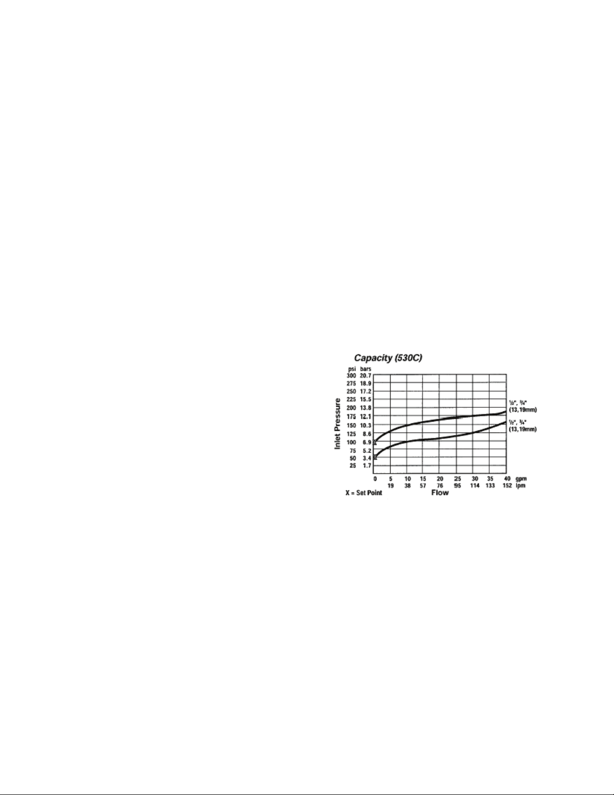
Pressure Relief Valve
Required pressure relief valve is installed in
the unit. This valve is set at 125 psig. Figure
1 shows inlet pressure versus capacity for
this pressure relief valve. See appendix for
additional information.
Figure 1 - Pressure Relief Valve
Manual and Automatic Air Vent
A manual air vent is supplied in chillers
without pumping packages. With a pumping
package option, there is an air scoop
installed at the high point of the system.
The air vent valve must be in the proper
position for operation. Ensure that the small
vent cap on the automatic air vent is
loosened one to two turns from the closed
position, allowing air to be vented from the
system. It is advisable to leave the cap on to
prevent impurities from entering the valve.
See appendix for additional information.
Page 15

Dual Pumps
When redundant pumping is required, a
factory installed dualArm pump can be
ordered on units 15 tons and larger. A
dualArm pump is a pump with two
independent motors and pumps in a single
casing. This pump has a swing split-flapper
valve in the discharge port to prevent liquid
recirculation when only one pump is
operating. Isolation valves in the casing
allow one pump to be isolated and removed
for service while the other pump is still
operating.
The controls package will activate the pump
when the unit is given a run command. If the
controls do not recognize flow in 60
seconds, the second pump will be activated
and an alarm signal will be generated. If the
second pump does not activate, the cooling
will be locked out.
Differential Pressure Gauge and Thermometers
A differential pressure gauge and
thermometers are available as a factory
installed option when using a factory
installed pumping package. Thermometers
are installed around the evaporator of the
unit. A differential pressure gauge is
installed at each pump. This pressure gauge
is connected in three places to the water
piping: before the suction guide/strainer,
after the suction guide and before the pump,
and after the pump. There is also a needle
valve at each of these points to isolate the
pressure. To measure the pressure at any
given point, open the needle valve at that
point and close the other two needle valves.
Instead of two pressure gauges, one pressure
gauge is used to minimize calibration and
gauge errors.
Pipe Insulation
All evaporators in the LC Series chiller are
heat traced and insulated. The water piping
and components on standard LC are not heat
traced or insulated at the factory. The
factory can install heat trace as an optional
feature. All water piping shall be leak tested
in the field prior to startup, as shipping
vibrations may have loosened connections.
Installation
Lifting the Unit
If cables or chains are used to hoist the unit
they must be the same length and care
should be taken to prevent damage to the
cabinet or injury to the installer.
Arrange spreader bars, blocking, or other
lifting devices to prevent any damage to the
coils or the cabinet of the condensing unit.
Before lifting unit, be sure that all shipping
material has been removed from the unit.
All LC Series chillers have lifting channels
in the base of the equipment to allow
moving and placement without physical
damage.
Unit may be positioned with a forklift.
Remove the harness used in hoisting. Make
sure the unit is properly seated and level.
Locating the Unit
The LC Series chiller is designed for
outdoor applications and mounting at
ground level or on a rooftop. It must be
placed on a level and solid foundation that
has been prepared to support its weight.
When installed at ground level, a one-piece
concrete slab should be used with footings
that extend below the frost line. Also with
ground level installation, care must be taken
to protect the coil fins from damage due to
vandalism or other causes. As a standard, all
15
Page 16
16
The chiller must be operated with
liquid flowing through the
attack by certain
chemicals. Polyolester (POE) oils
410A and other
and fittings and complete piping
system failure.
LC Series chillers have factory installed
louvered sheet metal condenser coil guards.
The placement relative to the building air
intakes and other structures must be
carefully selected. Airflow to and from the
chiller must not be restricted to prevent a
decrease in performance and efficiency.
The installation position must provide at
least 3 feet of side clearance for proper
airflow to the condenser coils. When units
are mounted adjacent to each other, the
minimum clearance required between the
units is 6 feet
Units should not be installed in an enclosure
or pit that is deeper than the height of the
unit. When recessed installation is
necessary, the clearance to maintain proper
airflow is at least 6 feet.
LC Series chillers have a vertical air
discharge. There must be no obstruction
above the equipment. Do not place the unit
under an overhang.
For proper unit operation, the immediate
area around condenser must remain free of
debris that may be drawn in and obstruct
airflow in the condensing section.
Consideration must be given to obstruction
caused by snow accumulation when placing
the unit.
Water Connection
Connect the chiller supply and return water
lines. The connection size is listed on the
unit rating sheet, along with the designed
volumetric flow rate. The maximum
operating pressure for the AAON LC Series
chiller is 125 psi.
evaporators.
PVC (Polyvinyl Chloride) and CPVC
(Chlorinated Polyvinyl Chloride) are
vulnerable to
used with Rrefrigerants, even in trace amounts,
in a PVC or CPVC piping system will
result in stress cracking of the piping
Mounting Isolation
For roof mounted applications or anytime
vibration transmission is a factor, vibration
isolators may be used.
Access Doors
Access doors are provided to the compressor
and electrical compartment. A separate
access door is also provided to the
evaporator/heat exchanger compartment.
Low Ambient Operation
During low ambient temperatures, it is
difficult to start a system because the
refrigerant will migrate to the cold part of
the system (condenser) and make it difficult
for refrigerant to flow. All chiller
compressors are provided with factory
installed crankcase heaters. The LC Series
chiller must have continuous power 24 hours
prior to startup. This ensures the compressor
will receive sufficient refrigerant vapor at
startup.
Page 17
The AAON low ambient (condenser floodback) system is used to operate a refrigerant
system below 25°F outside air temperature.
As the ambient temperature drops, the
condenser becomes more effective therefore
lowering the head pressure.
The low ambient system maintains normal
head pressure during periods of low ambient
by restricting liquid flow from the condenser
to the receiver, and at the same time
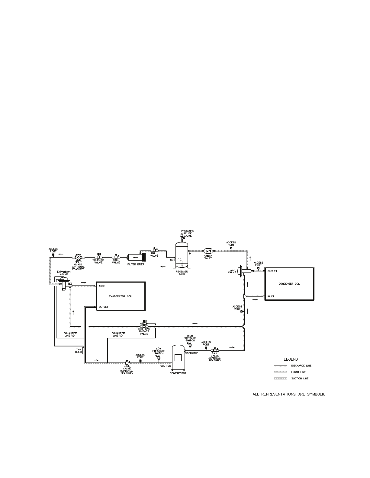
LAC Valve
The LAC valve is a non-adjustable three way valve that modulates to maintain receiver pressure.
As the receiver pressure drops below the valve setting (295 psig for R-410A), the valve
modulates to bypass discharge gas around the condenser. The discharge gas warms the liquid in
the receiver and raises the pressure to the valve setting. The following schematic shows an
example system using the LAC valve.
bypassing hot gas around the condenser to
the inlet of the receiver. This reduces liquid
refrigerant flow from the condenser,
reducing its effective surface area, which in
turn increases the condensing pressure. At
the same time the bypassed hot gas raises
liquid pressure in the receiver, allowing the
system to operate properly. LC Series
chillers use an LAC valve for low ambient
operation.
Figure 2 - Piping Schematic of Example System using the LAC Valve
17
Page 18

18
PERCENTAGE OF CONDENSER TO BE
FLOODED
70°
40°
Electric shock hazard. Before
ld result in
Condenser Flooding
In order to maintain head pressure in the
refrigeration system, liquid refrigerant is
kept in the condenser to reduce condenser
surface. The following chart shows the
percentage that a condenser must be flooded
in order to function properly at the given
ambient temperature.
Table 1 - Condenser Flooding
Ambient
Temperature
(
°F)
60°
50°
30°
20°
0°
Evaporating Temperature (
0° 10° 20° 30° 35° 40° 45° 50°
40 24 0 0 0 0 0 0
60 47 33 17 26 20 10 4
70 60 50 38 45 40 33 28
76 68 60 50 56 52 46 42
80 73 66 59 64 60 55 51
86 77 72 65 69 66 62 59
87 83 78 73 76 73 70 68
During higher ambient temperatures the
entire condenser is required to condense
refrigerant. During these higher ambient
temperatures, a receiver tank is used to
contain the refrigerant that was required to
flood the condenser during low ambient
operation. The receiver must be sized to
contain all of the flooded volume otherwise
there will be high head pressures during
higher ambient conditions.
Electrical
The single point electrical power
connections are made in the electrical
control compartment. The microprocessor
control furnished with the unit is supplied
with its own power supply factory wired to
the main power of the chiller.
Check the unit nameplate voltage to make
sure it agrees with the power supply.
°F)
Connect power to the unit according to the
wiring diagram provided with the unit.
Note: Units are factory wired for 208V,
230V, 460V, or 575V. In some units, the
208V and 230V options may also be
provided in single or three phase
configurations. The transformer
configuration must be checked by a
qualified technician prior to startup.
The power and control wiring may be
brought up through the utility entry. Protect
the branch circuit in accordance with code
requirements. Control wires and power
should not be run inside the same conduit.
The unit must be electrically grounded in
accordance with the current National
Electric Code.
Power wiring is to the unit terminal block or
main disconnect. All wiring beyond this
point has been done by the manufacturer and
cannot be modified without effecting the
unit’s agency/safety certification.
attempting to perform any installation,
service, or maintenance, shut off all
electrical power to the unit at the
disconnect switches. Unit may have
multiple power supplies. Failure to
disconnect power cou
dangerous operation, serious injury,
death or property damage.
Note: Startup technician must check motor
amperage to ensure that the amperage listed
on the motor nameplate is not exceeded.
Page 19

Rotation must be checked on all
units. All motors, to
observed to verify that all
Improper installation, adjustment,
alteration, service or maintenance
can cause property damage,
personal injury or loss of life.
Installation and service must be
Startup
(See back of the manual for startup form.)
Electric shock hazard. Shut off all
electrical power to the unit to avoid
shock hazard or injury from rotating
parts.
performed by a trained, qualified
installer.
Before startup of the chiller make sure that
the following items have been checked.
1. Verify that electrical power is available
to the unit.
2. Verify that any remote stop/start device
connected to the chiller controller is
requesting the chiller to start.
3. Verify that liquid flow is present through
the chiller from the building.
4. There should be a building load of at
least 25% of the chiller capacity in order
to properly check operation.
5. With the main power switch off, review
the Controller Manual provided with the
chiller. Understand the keypad functions,
how to set the leaving water temperature
setpoint and how to initiate the Run
State.
Use the general check list at the top of the
startup form to make a last check that all the
components are in place, water flow is
present, and the power supply is energized.
Using the controller keypad, individually set
the outputs in “Manual On” to confirm relay
closure and compressor operation.
MOTORS AND COMPRESSORS of
three phase
include and not be limited to pump
motors and condenser fan motors,
should all be checked by a qualified
service technician at startup and any
wiring alteration should only be made
at the unit power connection.
Cycle through all the compressors to
confirm that all are operating within
tolerance.
While performing the check, use the startup
form to record observations of amps and
refrigerant pressures.
When all is running properly, place the
controller in the Run mode and observe the
system until it reaches a steady state of
operation.
Note: For more information on
programming the controller refer to the
MCS Controller manual provided with the
unit.
Before completing installation, a
complete operating cycle should be
components are functioning properly.
19
Page 20

20
Circuit Loading
Max. Pressure Drop
100%
10 psig
50%
5 psig
intentional venting of refrigerant
recycling or reclaiming must be
Maintenance
General
Qualified technicians must perform routine
service checks and maintenance. This
includes reading and recording the
condensing and suction pressures and
checking for normal sub-cooling and
superheat.
Compressors
The scroll compressors are fully hermetic
and require no maintenance except keeping
the shell clean.
Refrigerant Filter Driers
Each refrigerant circuit contains a filter
drier. Replacement is recommended when
there is excessive pressure drop across the
assembly or moisture is indicated in a liquid
line sight glass.
Evaporator
The evaporators are direct expansion type
with a thermal expansion valve to regulate
refrigerant. Normally no maintenance or
service work will be required.
Adjusting Refrigerant Charge
All AAON chillers are shipped with a full
factory charge. Periodically additional
charge may be required.
Charging a system in the field must be based
on determination of liquid sub-cooling and
evaporator superheat. On a system with a
thermostatic expansion valve liquid subcooling is more representative of the charge
than evaporator superheat but both
measurements must be taken.
The Clean Air Act of 1990 bans the
(CFC’s and HCFC’s) as of July 1,
1992. Approved methods of recovery,
followed. Fines and/or incarceration
may be levied for non-compliance.
Before Charging
Refer to the Unit Nameplate as a reference
when determining the proper refrigerant
charge.
Unit being charged must be at or near full
load conditions before adjusting the charge.
After adding or removing charge the system
must be allowed to stabilize, typically 10-15
minutes, before making any other
adjustments.
The type of unit and options determine the
ranges for liquid sub-cooling and evaporator
superheat. Refer to Table 2 when
determining the proper sub-cooling.
Checking Liquid Sub-cooling
Measure the temperature of the liquid line as
it leaves the condenser coil.
Read the gauge pressure at the liquid line
close to the point where the temperature was
taken. You must use liquid line pressure as it
will vary from discharge pressure due to
condenser coil pressure drop.
Convert the pressure obtained to a saturated
temperature using the appropriate refrigerant
temperature-pressure chart.
Subtract the measured liquid line
temperature from the saturated temperature
to determine the liquid sub-cooling.
Page 21

Air-Cooled Condenser
Sub-Cooling
2
12-18°F
Superheat
1
10-15°F
suction superheat. Failure to have
Refrigerant overcharging leads to
CAUTION
Compare calculated sub-cooling to the table
Table 2 - Acceptable Refrigeration Circuit
Values
below for the appropriate unit type and
options.
Checking Evaporator Superheat
Measure the temperature of the suction line
close to the compressor.
Read gauge pressure at the suction line close
to the compressor.
Convert the pressure obtained to a saturated
temperature using the appropriate refrigerant
temperature-pressure chart.
Subtract the saturated temperature from the
measured suction line temperature to
determine the evaporator superheat.
For refrigeration systems with tandem
compressors, it is critical that the suction
superheat setpoint on the TXV is set with
one compressor running. The suction
superheat should be 10-13°F with one
compressor running. The suction superheat
will increase with both compressors in a
tandem running. Inadequate suction
superheat can allow liquid refrigerant to
return to the compressors which will wash
the oil out of the compressor. Lack of oil
lubrication will destroy a compressor.
Liquid sub-cooling should be measured with
both compressors in a refrigeration system
running.
Compare calculated superheat to Table 2 for
the appropriate unit type and options.
1
One compressor running in tandem
2
Two compressors running in tandem
Thermal expansion valves must be
adjusted to approximately 10-15°F of
sufficient superheat will damage the
compressor and void the warranty.
Adjusting Sub-cooling and Superheat
Temperatures
The system is overcharged if the sub-cooling
temperature is too high and the evaporator is
fully loaded (low loads on the evaporator
result in increased sub-cooling) and the
evaporator superheat is within the
temperature range as shown in
Table 2 (high
superheat results in increased sub-cooling)
Correct an overcharged system by reducing
the amount of refrigerant in the system to
lower the sub-cooling.
DO NOT OVERCHARGE!
excess refrigerant in the condenser
coils resulting in elevated compressor
discharge pressure.
21
Page 22

22
°F
PSIG
°F
PSIG
°F
PSIG
°F
PSIG
°F
PSIG
20
78.3
47
134.7
74
213.7
101
321.0
128
463.2
21
80.0
48
137.2
75
217.1
102
325.6
129
469.3
22
81.8
49
139.7
76
220.6
103
330.2
130
475.4
23
83.6
50
142.2
77
224.1
104
334.9
131
481.6
24
85.4
51
144.8
78
227.7
105
339.6
132
487.8
25
87.2
52
147.4
79
231.3
106
344.4
133
494.1
26
89.1
53
150.1
80
234.9
107
349.3
134
500.5
27
91.0
54
152.8
81
238.6
108
354.2
135
506.9
28
92.9
55
155.5
82
242.3
109
359.1
136
513.4
29
94.9
56
158.2
83
246.0
110
364.1
137
520.0
30
96.8
57
161.0
84
249.8
111
369.1
138
526.6
31
98.8
58
163.8
85
253.7
112
374.2
139
533.3
32
100.9
59
166.7
86
257.5
113
379.4
140
540.1
33
102.9
60
169.6
87
261.4
114
384.6
141
547.0
34
105.0
61
172.5
88
265.4
115
389.9
142
553.9
35
107.1
62
175.4
89
269.4
116
395.2
143
560.9
36
109.2
63
178.4
90
273.5
117
400.5
144
567.9
37
111.4
64
181.5
91
277.6
118
405.9
145
575.1
38
113.6
65
184.5
92
281.7
119
411.4
146
582.3
39
115.8
66
187.6
93
285.9
120
416.9
147
589.6
40
118.1
67
190.7
94
290.1
121
422.5
148
596.9
41
120.3
68
193.9
95
294.4
122
428.2
149
604.4
42
122.7
69
197.1
96
298.7
123
433.9
150
611.9
43
125.0
70
200.4
97
303.0
124
439.6
44
127.4
71
203.6
98
307.5
125
445.4
45
129.8
72
207.0
99
311.9
126
451.3
46
132.2
73
210.3
100
316.4
127
457.3
The system is undercharged if the superheat
is too high and the sub-cooling is too low.
Correct an undercharged system by adding
refrigerant to the system to reduce superheat
and raise sub-cooling.
Table 3 - R-410A Refrigerant Temperature-Pressure Chart
If the sub-cooling is correct and the
superheat is too high, the TXV may need
adjustment to correct the superheat.
Page 23

Lubrication
All original motors and bearings are
furnished with an original factory charge of
lubrication. Certain applications require
bearings be re-lubricated periodically. The
schedule will vary depending on operating
duty, temperature variations, or severe
atmospheric conditions.
Bearings should be re-lubricated at normal
operating temperatures, but not when
running.
Rotate the fan shaft by hand and add only
enough grease to purge the seals. DO NOT
OVERLUBRICATE.
Service
If the unit will not operate correctly and a
service company is required, only a
company with service technicians qualified
and experienced in both refrigerant chillers
and air conditioning are permitted to service
the systems to keep warranties in effect. If
assistance is required, the service technician
must contact AAON.
Note: Service technician must provide the
model and serial number of the unit in all
correspondence with AAON.
Replacement Parts
Parts for AAON equipment may be obtained
from AAON through customer service.
When ordering parts, reference serial
number and part number located on the
external or internal nameplate of the unit.
AAON - Longview Warranty, Service and Parts Department
203 Gum Springs Rd.
Longview, TX 75602
Ph: 903-236-4403
Fax: 903-236-4463
www.aaon.com
Note: Before calling, technician should have
model and serial number of the unit
available for the customer service
department to help answer questions
regarding the unit.
Warranties
Please refer to the limitation of warranties in
effect at the time of purchase.
Condenser Tube Inspection
The coils are leak tested at 650 psig, before
shipment. AAON will not be responsible for
loss of refrigerant. It is the responsibility of
the installer to verify that the system is
sealed before charging with refrigerant.
Pump Operation
Before initial start of the pump, check as
follows:
1. Be sure that pump operates in the
direction indicated by the arrow on the
pump casing. Check rotation each time
motor leads have been disconnected.
2. Check all connections of motor and
starting device with wiring diagram. Check
voltage, phase and frequency of line circuit
with motor name plate.
3. Check suction and discharge piping and
pressure gauges for proper operation.
4. Turn rotating element by hand to assure
that it rotates freely.
Running:
Periodically inspect pump while running,
but especially after initial start-up and after
repairs.
1. Check pump and piping for leaks. Repair
immediately.
2. Record pressure gauge readings for future
reference.
3. Record voltage, amperage per phase, and
kW.
23
Page 24

24
Maintenance Recommendations
Pump/Fan Motor Maintenance
Cleaning - Remove oil, dust, water, and
chemicals from exterior of motor and pump.
Keep motor air inlet and outlet open. Blow
out interior of open motors with clean
compressed air at low pressure.
Labeled Motors - It is imperative for repair
of a motor with Underwriters’ Laboratories
label that original clearances be held; that all
plugs, screws, other hardware be fastened
securely, and that parts replacements be
exact duplicates or approved equals.
Violation of any of the above invalidates
Underwriters’ Label.
Access Doors
If scale deposits or water is found around the
access doors, adjust door for tightness.
Adjust as necessary until leaking stops when
door is closed.
Pump Bearings - Lubrication
Every 6 months or after a prolonged shut
down, use waterproof, lithium based grease.
Below 32°F, use Esso Exxon or Beacon 325.
Above 32°F, use Mobil Mobilox EP2, Shell
Alvania EP2 or Texaco RB2.
Air Inlet
Inspect the air inlet louvers into the
condenser section on a monthly basis to
remove any paper, leaves or other debris that
may block the airflow.
Recommended Annual Inspection
In addition to the above maintenance
activities, a general inspection of the unit
surface should be completed at least once a
year.
Mechanical Cleaning
Do not attempt to mechanically clean the
copper tubing in the condenser. Do not use
wire brushes or any other mechanical device
on the copper tubing. Severe damage may
result. Contact your water treatment expert
for recommendations on chemical cleaning
procedures.
Air-Cooled Condenser
The air-cooled condenser section rejects
heat by passing outdoor air over the fin tube
coils for cooling of the hot refrigerant gas
from the compressors. The heated air will
discharge from the top of the section
through the axial flow fans.
The condenser coils should be inspected
yearly to ensure unrestricted airflow. If the
installation has a large amount of airborne
dust or other material, the condenser coils
should be cleaned with a water spray in a
direction opposite to airflow. Care must be
taken to prevent bending of the aluminum
fins on the copper tubes.
E-Coated Coil Cleaning
Documented routine cleaning of e-coated
coils is required to maintain coating
warranty coverage.
Propeller Fans and Motors
The fans are directly mounted on the motor
shafts and the assemblies require minimal
maintenance except to assure they are clear
of dirt or debris that would impede the
airflow.
Electric shock hazard. Shut off all
electrical power to the unit to avoid
shock hazard or injury from rotating
parts.
Page 25

surface of the coil, use the
washer or compressed air should
bend the fin edges and increase
performance or nuisance unit
CAUTION
Surface loaded fibers or dirt should be
removed prior to water rinse to prevent
restriction of airflow. If unable to back wash
the side of the coil opposite of the coils
entering air side, then surface loaded fibers
or dirt should be removed with a vacuum
cleaner. If a vacuum cleaner is not available,
a soft non-metallic bristle brush may be
used. In either case, the tool should be
applied in the direction of the fins. Coil
surfaces can be easily damaged (fin edges
bent over) if the tool is applied across the
fins. Use of a water stream, such as a garden
hose, against a surface loaded coil will drive
the fibers and dirt into the coil. This will
make cleaning efforts more difficult. Surface
loaded fibers must be completely removed
prior to using low velocity clean water rinse.
A monthly clean water rinse is
recommended for coils that are applied in
coastal or industrial environments to help to
remove chlorides, dirt, and debris. It is very
important when rinsing, that water
temperature is less than 130° F and pressure
is less than 900 psig to avoid damaging the
fin edges. An elevated water temperature
(not to exceed 130° F) will reduce surface
tension, increasing the ability to remove
chlorides and dirt.
High velocity water from a pressure
only be used at a very low pressure
to prevent fin and/or coil damages.
The force of the water or air jet may
airside pressure drop. Reduced unit
shutdowns may occur.
Quarterly cleaning is essential to extend
the life of an e-coated coil and is required
to maintain coating warranty coverage.
Coil cleaning shall be part of the unit’s
regularly scheduled maintenance
procedures. Failure to clean an e-coated coil
will void the warranty and may result in
reduced efficiency and durability.
Harsh chemicals, household bleach,
or acid cleaners should not be used
to clean outdoor or indoor e-coated
coils. These cleaners can be very
difficult to rinse out of the coil and
can accelerate corrosion and attack
the e-coating. If there is dirt below the
recommended coil cleaners.
For routine quarterly cleaning, first clean the
coil with the following approved coil
cleaner. After cleaning the coils with the
approved cleaning agent, use the approved
chloride remover to remove soluble salts and
revitalize the unit.
Recommended Coil Cleaner
The following cleaning agent, assuming it is
used in accordance with the manufacturer’s
directions on the container for proper mixing
and cleaning, has been approved for use on
e-coated coils to remove mold, mildew,
dust, soot, greasy residue, lint, and other
particulate:
Enviro-Coil Concentrate, Part Number HEC01.
Recommended Chloride Remover
CHLOR*RID DTS™ should be used to
remove soluble salts from the e-coated coil,
but the directions must be followed closely.
This product is not intended for use as a
degreaser. Any grease or oil film should first
25
Page 26

26
be removed with the approved cleaning
agent.
Remove Barrier - Soluble salts adhere to the
substrate. For the effective use of this
product, the product must be in contact with
the salts. These salts may be beneath any
soils, grease or dirt; therefore, these barriers
must be removed prior to application of this
product.
Apply CHLOR*RID DTS - Apply directly
onto the substrate. Sufficient product must
be applied uniformly across the substrate to
thoroughly wet out surface, with no areas
missed. This may be accomplished by use of
a pump-up sprayer or conventional spray
gun. The method does not matter, as long as
the entire area to be cleaned is wetted. After
the substrate has been thoroughly wetted,
the salts will be soluble and is now only
necessary to rinse the salts off.
Rinse - It is highly recommended that a hose
be used. A pressure washer on a high
pressure setting will damage the fins. The
water to be used for the rinse is
recommended to be of potable quality,
though a lesser quality of water may be used
if a small amount of CHLOR*RID DTS is
added. Check with CHLOR*RID
International, Inc. for recommendations on
lesser quality rinse water.
Page 27

Appendix - Water Piping Component Information
Water Pressure Relief Valve
Overview
ASME Rated, Design Certified and Listed
by C.S.A.
Used for protection against excessive
pressure on domestic storage tanks or tankless water heaters, the pressure relief valve
has no temperature relieving element.
Standard setting is 125 psi Size 3⁄4 ” x 3⁄4 ”
(20mm x 20mm). ASME construction and is
tested, listed and certified by the National
Board of Boiler and Pressure Vessel
Inspectors.
ANSI Z21.22 “Relief Valves for Hot Water
Supply Systems.”
DESIGN CERTIFIED and listed by C.S.A.
Automatic Air Vent Valves
Automatic Air Vent Valves provide air
venting for hot or cold water distribution
systems. These vents purge air that may be
in the water system.
The vent valve utilizes an internal baffle
system. The baffles slow water so that
entrapped air can separate. Once the air is
separated, the air migrates to the top of the
scoop chamber. The air is vented through
the factory installed vent.
Overview
Air scoops are constructed of one piece cast
iron. Baffles are engineered to separate air
from water. All air scoops come with 1/8”
vent connection. An additional stainless
steel expansion tank connection is available
on the 1-1/2” to 4” air scoops. Air scoops
never require servicing. The high point vent
should be turned clockwise one to two
rotations to allow proper air venting. It is
not recommended to remove the cap as dirt
and debris may enter the water system.
Air scoops are suitable for use with water or
water/glycol systems.
Operating Range
Maximum operating pressure:
125 psi (862 kPa)
Maximum operating temperature:
Recommended Flow Rate:
Maximum Flow Rate:
300ºF (135ºC)
4 ft. / sec.
8 ft. / sec.
27
Page 28
28
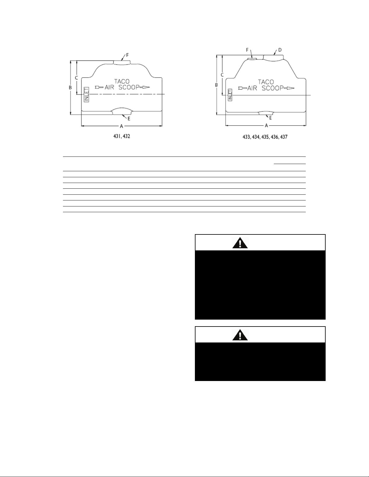
Dimensions & Weights
Weight
Lbs
Kg.
431
1”
6”
4”
2-1/2”
**
1/2” NPT
1/8” NPT
31.4 4 1.8
432
1-1/4”
6”
4”
2-1/2”
**
1/2” NPT
1/8” NPT
53.5 4 1.8
433
1-1/2”
8”
6”
4”
3/4” NPT
1/2” NPT
1/8” NPT
61 7 3.2
434
2”
8”
6”
4”
3/4” NPT
1/2” NPT
1/8” NPT
106.6 7 3.2
435
2-1/2”
10”
8”
5-1/2”
1” NPT
1/2” NPT
1/8” NPT
140
15
6.8
436
3”
10”
8”
5-1/2”
1-1/4” NPT
1/2” NPT
1/8” NPT
276
14
6.4
*This size has 125 lb. flanged ends.
**No conventional plain steel expansion tank tapping.
Improper installation, adjustment,
alteration, service or maintenance
can cause property damage,
personal injury or loss of life.
Installation and service must be
Product
Number Size A B C D E F Cv
437* 4” 16-5/16” 11-5/8” 7-1/8” 1-1/2” NPT 1/2” NPT 1/8” NPT 600 52 23.6
Pumps: Installation and Operating Instructions
Introduction
This document contains specific information
regarding the safe installation, operating and
maintenance of Vertical In-Line pumps and
should be read and understood by installing,
operating and maintenance personnel. The
equipment supplied has been designed and
constructed to be safe and without risk to
health and safety when properly installed,
operated and maintained. The instructions
following must be strictly adhered to. If
clarification is needed on any point please
contact Armstrong quoting the equipment
serial number.
performed by a trained, qualified
installer.
Installation of this equipment should
not take place unless this document
has been read and understood.
Where under normal operating conditions
the limit of 68°C/155°F (Restricted Zone)
for normal touch, or 80°C/176°F
(Unrestricted Zone) for unintentional touch,
Page 29

may be experienced, steps should be taken
to minimize contact or warn operators/users
that normal operating conditions will be
exceeded. In certain cases where the
temperature of the pumped liquid exceeds
the above stated temperature levels, pump
casing temperatures may exceed
100°C/212°F and not withstanding pump
insulation techniques appropriate measures
must be taken to minimize risk for operating
personnel.
Storage
Pumps removed from service and stored,
must be properly prepared to prevent
excessive rusting. Pump port protection
plates must not be removed until the pump is
ready to connect to the piping. Rotate the
shaft periodically (At least monthly) to keep
rotating element free and bearings fully
functional.
For long term storage, the pump must be
placed in a vertical position in a dry
environment. Internal rusting can be
prevented by removing the plugs at the top
and bottom of the casing and drain or air
blow out all water to prevent rust buildup or
the possibility of freezing. Be sure to
reinstall the plugs when the unit is made
operational. Rust proofing or packing the
casing with moisture absorbing material and
covering the flanges is acceptable. When
returning to service, be sure to remove the
drying agent from the pump.
Handling Large VIL Units
One effective way of lifting a large pumping
unit is to place lifting hooks through the
motor lifting rings or straps around the
upper part of the motor. The pump and
motor unit will free-stand on the casing ribs.
Remove the coupling guard and place (2)
lifting straps through the pump/motor
pedestal, one on each side of the motor shaft
and secure to the lifting device.
With the straps in place, using a spacer bar if
necessary to protect the motor fan cover, the
whole assembly can now be lifted securely.
Note: Handling, transportation and
installation of this equipment should only
undertaken by trained personnel with proper
use of lifting equipment.
Remove coupling guard and place lifting
straps on each side of coupling, use spacer
bar if necessary to protect motor fan cover.
Vertical Inline Pump Lifting Strap
Positioning:
Note:
All split-coupled pumps contain a tapped
hole in the motor bracket above the
discharge flange for draining the well. Pipe
this drain hole to a floor drain to avoid
overflow of the cavity caused by collecting
chilled water condensate or from seal
failure.
29
Page 30

30
Do not run pumps with discharge
Pump Piping - General
Piping may carry high temperature
fluid.
Discharge valve only is to be used to
throttle pump flow.
Caution
The discharge valve only is to be used to
throttle pump flow, not the suction valve.
Care must be taken in the suction line layout
and installation, as it is usually the major
source of concern in centrifugal pump
applications
Alignment
Alignment is unnecessary on close-coupled
pumps as there is no shaft coupling.
Split-coupled units are accurately aligned at
the factory prior to being shipped and do not
need re-aligning when installed.
Operation
valve closed or under very low flow
conditions.
Starting Pump
Ensure that the pump turns freely by hand,
or with some mechanical help such as a
strap and lever on larger pumps. Ensure that
all protective guarding is securely fixed in
The pump must be fully primed on start up.
Fill the pump casing with liquid and rotate
the shaft by hand to remove any air trapped
in the impeller. On split coupled units, any
air trapped in the casing as the system is
filled must be removed by the manual air
vent in the seal flush line. Close-coupled
units are fitted with seal flush/vent lines
piped to the pump suction area. When these
units operate residual air is drawn out of the
pump towards the suction piping.
Energize the motor momentarily and check
that the rotation corresponds with the
directional arrow on the pump casing.
To reverse rotation of a three phase motor,
interchange any two power leads.
Start the pump with the discharge valve
closed and the suction valve open, and then
gradually open the discharge valve when the
motor is at operating speed. The discharge
valve may be opened slightly at start up to
help eliminate trapped air.
When stopping the pump: Close the
discharge valve and de-energize the motor.
DO NOT run the pump against a closed
discharge valve for an extended period of
time (A few minutes maximum).
Star-Delta motor starters should be fitted
with electronic/mechanical interlocks that
have a timed period of no more than 40
milliseconds before switching from star
(Starting) to delta (Run) connection yet
allow the motor to reach full star (Starting)
speed before switching to delta (Run).
Should the pump be noisy or vibrate on
start-up a common reason is overstated
system head. Check this by calculating the
pump operating head by deducting the
suction pressure gauge value from the
position.
Page 31

Check rotation arrow prior to
Electric shock hazard. Before
maintenance on pumping unit,
disconnect power source to drive,
LOCK IT OFF and tag with the
discharge gauge reading. Convert the result
into the units of the pump head as stated on
the pump nameplate and compare the
values. Should the actual pump operating
head be significantly less than the nameplate
head value it is typically permissible to
throttle the discharge isolation valve until
the actual operating head is equal to the
nameplate value.
Any noise or vibration usually disappears.
The system designer or operator should be
made aware of this soon as some adjustment
may be required to the pump impeller
diameter or drive settings, if applicable, to
make the pump suitable for the system as
installed.
operating the unit.
Check rotation arrow prior to operating the
unit. The rotation of all Vertical In-Line
units is “clockwise” when viewed from the
drive end. (Looking from on top of / behind
the motor)
General Care
Vertical In-Line pumps are built to operate
without periodic maintenance, other than
motor lubrication on larger units. A
systematic inspection made at regular
intervals, will ensure years of trouble-free
operation, giving special attention to the
following:
Keep unit clean. Keep moisture, refuse, dust
or other loose particles away from the pump
and ventilating openings of the motor
Avoid operating the unit in overheated
surroundings (Above 100ºF/40ºC).
attempting to perform any service or
reason.
Any possibility of the unit starting while
being serviced must be eliminated.
If mechanical seal environmental
accessories are installed, ensure water is
flowing through the sight flow indicator and
that filter cartridges are replaced as
recommended.
Lubrication
Pump
Lubrication is not required. There are no
bearings in the pump that need external
lubrication service.
Motor
Follow the lubrication procedures
recommended by the motor manufacturer.
Many small and medium sized motors are
permanently lubricated and need no added
lubrication. Generally if there are grease
fittings evident the motor needs periodic
lubrication, and if there are no grease fittings
evident, no periodic lubrication is required.
Check the lubrication instructions supplied
with the motor for the particular frame size
indicated on the motor nameplate.
Mechanical Seal
Mechanical seals require no special
attention. The mechanical seal is fitted with
a flush line. The seal is flushed from
discharge of the pump casing on split-
31
Page 32
32
coupled pumps and is flushed and vented to
the suction on close coupled pumps.
The split-coupled pump is flushed from the
pump discharge because the mechanical seal
chamber is isolated from the liquid in the
pump by a throttle bushing. Because the seal
chamber is isolated, seal environmental
controls such as filters and separators, when
installed in the split-coupled flush line are
very effective, as only the seal chamber
needs cleansing, and will prolong seal life in
HVAC systems.
Do not run the pump unless properly filled
with water as the mechanical seals need a
film of liquid between the faces for proper
operation.
Mechanical seals may ‘weep’ slightly at
start-up. Allow the pump to continue
operating for several hours and the
mechanical seal to ‘seat’ properly prior to
calling for service personnel.
System Cleanliness
Before starting the pump the system must be
thoroughly cleaned, flushed and drained and
replenished with clean liquid.
Welding slag and other foreign materials,
“Stop Leak” and cleaning compounds and
improper or excessive water treatment are
all detrimental to the pump internals and
sealing arrangement.
Proper operation cannot be guaranteed if the
above conditions are not adhered to.
Double Check Prior to Startup.
Note:
Particular care must be taken to check the
following before the pump is put into
operation:
1. Pump primed?
2. Rotation OK?
3. Lubrication OK?
4. Pipe work properly supported?
5. Voltage supply OK?
6. Overload protection OK?
7. Is the system clean?
8. Is the area around the pump clean?
Warranty
Does not cover any damages to the
equipment resulting from failure to observe
the above precautions.
Page 33

Noise Levels
Estimated Pumping Unit Sound Power Level, (Decibels), A-Weighted, at 1 m (3 ft.) from unit.
Vibration Levels
Vertical In-Line pumps are designed to meet vibration levels set by Hydraulic Institute Standard
HI Pump Vibration 9.6.4. Standard levels are as detailed below:
Dual Pump Specific Information
Dual Pump Flapper Valve Operating
Instructions
This unit is fitted with internal valves to
allow isolation of one pump for service and
to automatically prevent recirculation of the
flow when only one pump is running.
Procedure for Parallel or Stand-By
Pumping:
Discharge and suction valve stems should be
locked in the center position. This is
indicated by both locking handles in the
vertical position and the center pin of the
procedure allows the discharge flapper
valves to pivot freely and locks the suction
valve firmly in the center position.
Procedure for Isolation of One Side:
1. Stop the pump to be serviced.
2. Close and lock the suction and discharge
valves: as per instructions below.
3. Ensure seal flush line interconnection
valve is closed and drain the isolated casing.
4. Service isolated pump as required.
locking arms (4) locked by the handles. This
33
Page 34

34
Procedure for Starting the Pump after
Servicing:
1. Ensure serviced pump is fully re-
assembled including all seal flush lines and
drain plugs.
2. Fill the dry casing with system fluid by
opening the seal flush line interconnecting
valve and the air vent fitting.
3. Allow the pressure to equalize in the two
casings, if necessary, by opening seal flush
line interconnected valve.
4. Unlock the discharge valve as per
instructions below.
5. Unlock the suction valve as per
instructions below.
NOTE: Keep hands and tools away from
locked suction valve arm, as the differential
pressure may cause the arm to rotate quickly
with force when unlocked.
6. Close the seal flush line interconnect
valve and restart pump.
Valve Operation
Refer to the valve illustrations on the following pages.
Discharge Valve
This valve performs the dual function of
automatically sealing the discharge of the
inactive pump when one pump is running
and can manually be closed and locked to
isolate one pump for service.
Automatic Flapper Operation
In the flapper mode the two halves of the
discharge valve are free to pivot
independently under normal operating
conditions. The locking handle (3) should be
secured with the set screw (11) in the
vertical position with the center pin of the
locking arm (4) trapped by the locking
handle (3).
Manual Valve Locking:
The locking feature of this valve is to ensure
a positive seal (leak proof) of the discharge
port on the pump to be serviced.
Note: Ensure the pump to be isolated is not
operating before attempting to release the
locking mechanism. Failure to do so may
result in injury to the operator and/or
damage to the pump.
Locking
1. Loosen discharge side set screw (11) to
release the locking handle (3).
2. Rotate the discharge side locking handle
(3) so that the handle points toward the
pump to be serviced and secure in the
horizontal position, using set screw (11).
This releases the discharge locking arm (4).
3. Rotate discharge valve shaft (16) towards
the pump to be isolated. The orientation of
the shaft is indicated by the center pin on the
locking arm. (4).
4. Raise the locking handle (3) so that the
cam on the base of the handle forces the pin
of the locking arm (4) towards the pump to
be isolated. The locking handle (3) should
be raised to between 45 degrees and the
vertical position.
5. Tighten set screw (11) to lock the locking
handle (3) in position
THIS HANDLE SHOULD NOT BE
ROTATED PAST THE VERTICAL
POSITION.
Note: Ensure the isolated pump is not
operating before attempting to release the
locking mechanism. Failure to do so may
result in injury to the operator and/or
damage the pump.
Page 35
Care should be taken when
Care should be taken when
Unlocking:
1. Open the interconnecting valve on the
seal flush line to pressurize the serviced
pump and vent air through bleeder valve on
series 4302.
Close these valves once the pressure is
equalized and air removed.
2. Loosen set screw (11) and lower locking
handle (3) to the horizontal position, secure
with set screw (11).
3. Rotate valve to center position so that the
center pin of the locking arm (4) locates in
the recess on the locking handle (3).
4. Loosen set screw (11) and raise locking
arm (3) to the vertical position, locking the
center pin in the locking arm recess, secure
with set screw (11).
Suction Valve
Manual Operation:
The suction side valve is designed for use as
a manually operated isolation valve. This
valve is not designed to automatically pivot
as the discharge flappers do.
performing procedures 3 and 4. Read
instructions carefully.
Locking:
1. Loosen suction side set screw (11) to
release the locking handle (3).
2. Rotate the suction side locking handle (3)
so that the handle points towards the pump
to be serviced and secure in the horizontal
position, using set screw (11). This releases
the suction locking arm (4).
Note: The locking handle (3) should only be
rotated towards the pump stopped for
service. The suction valve is designed to
prevent the locking handle (1) from rotating
towards the running pump, as the suction of
the running pump could cause the valve to
slam shut with sufficient force to injure the
operator and/or cause damage to the pump.
Do not attempt to circumvent this safety
feature.
3. Rotate the suction valve towards the
pump to be isolated. The orientation of the
shaft is indicated by the center pin on the
locking arm (4).
4. Loosen set screw (11) and raise the
locking handle (3) so that the cam on the
base on the handle forces the pin of the
locking arm (4) towards the pump to be
isolated. The locking handle (3) should be
raised to between 45 degrees and the vertical
position.
THIS HANDLE SHOULD NOT BE
ROTATED PAST THE VERTICAL
POSITION.
5. Tighten set screw (11) to secure the
locking handle (3) in position.
performing procedures 3 and 4. Read
instructions carefully.
Unlocking:
1. Open the interconnecting valve on the
seal flush line to pressurize the serviced
pump and vent air through bleeder valve on
series 4302. Close these valves once the
pressure is equalized and air removed.
2. Loosen set screw (11) and lower locking
handle (3) to the horizontal position, secure
with set screw (11).
NOTE: Keep hands and tools away from
suction valve locking arm when freed by
locking handle as differential pressure may
35
Page 36

36
cause arm to rotate quickly with force when
unlocked.
3. Rotate valve to center position so that the
center pin of the locking arm (4) is located
in the recess on the locking handle (3).
4. Loosen set screw (11) and raise locking
arm (3) to the vertical position, locking the
center pin in the locking arm recess, secure
with set screw.
Page 37

37
Page 38

38
Page 39
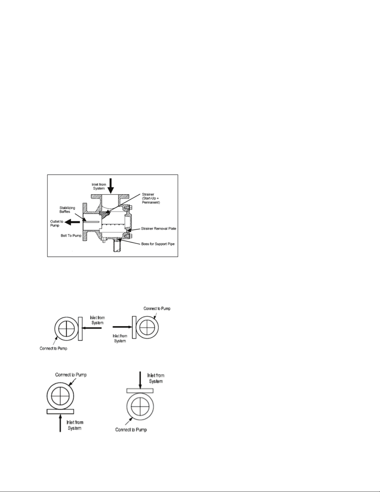
39
Suction Guides
Introduction
Suction guides are designed for bolting
directly onto the suction flange of horizontal
or vertical shaft centrifugal pumps.
Operating Limits
The suction guide is designed to be a fourfunction fitting. Each Suction Guide is a 90º
elbow, a Pipe Strainer and a Flow Stabilizer.
It may also be used as a Reducing Elbow,
should the suction piping be larger than the
pump inlet.
Installation
The suction guides may be installed in any
arrangement feasible the arrangement of the
pump flange bolt-holes.
Inspection
Suction guides are thoroughly tested and
inspected before shipment to assure they
meet with your order requirements. All units
must be carefully examined upon arrival for
possible damage during transit. Any
evidence of mishandling should be reported
immediately to the carrier and noted on the
freight bill.
Operation
No special attention need be paid to the
Suction Guide at start-up. The fitting is
stationary and will strain the pumped fluid
and stabilize the flow into the pump
automatically.
Temporary strainer must be removed
following system clean up.
After all debris has been removed from the
system, or a maximum of 24 running hours,
stop the pump and close the pump isolation
valves. Drain the Suction Guide by
removing the drain plug or opening the
blowdown valve, if installed.
Remove the Suction Guide cover and
remove the strainer assembly from the valve
body.
A temporary fine-mesh start-up strainer is
tack-welded to the permanent stainless steel
strainer. This temporary strainer should now
be removed from the permanent strainer.
The fine-mesh strainer is designed to
remove small particulate from new piping
systems and could easily clog with debris if
left in place. This will be detrimental to the
operation of the pump.
Inspect the cover O-ring and replace if
necessary.
Page 40
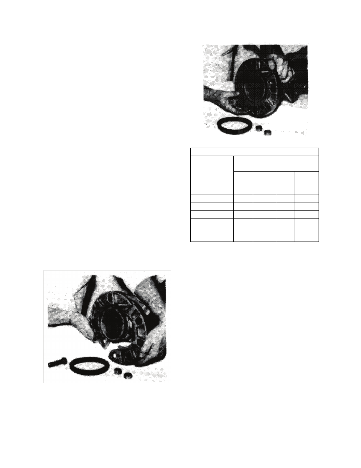
40
Armgrip Flange Adapter Details
Ductile Iron Bolt
Ductile Iron Bolt
4
8
5/8 8 3/4
10
12
7/8
16 1 12
12
7/8
16
1-1/8
Replace the permanent strainer into the
fitting body, once the temporary strainer is
removed.
Replace the cover into the body. Ensuring
that the strainer is properly seated, tighten
the cover bolts diagonally, evenly and
firmly.
Flo-Trex Combination Valve
Introduction
The Flo-Trex combination valves are
designed for installation on the discharge
side of centrifugal pumps, and incorporate
three functions in one valve:
1. Drip-tight shut-off valve
2. Spring closure design, Non-slam check
valve
3. Flow throttling valve
Armgrip Flange Adapter installation
1. Position the two halves of the Armgrip
flange adapter on the valve body ensuring
that the lugs on each half of the flange
adapters are located between the antirotation lugs on the valve body (as shown).
Insert two bolts of specified size (Table A1)
to secure the halves of the flange adapter to
the valve body (as shown).
125 psi/150 psi 250 psi/300 psi
Valve Size
No. Size No. Size
2-1/2 4 5/8 8 3/4
3 4 5/8 8 3/4
5 8 3/4 8 3/4
6 8 3/4 12 3/4
8 8 3/4 12 7/8
The gasket cavity should face out to the
adjoining flange.
2. Lubricate the inner and outer diameter of
the gasket with the lubricant provided or a
similar non-petroleum based water soluble
grease.
3. Press the gasket firmly into the flange
cavity ensuring that the sealing lip is pointed
outward. When in place, the gasket should
not extend beyond the end of the pipe (as
shown).
Page 41
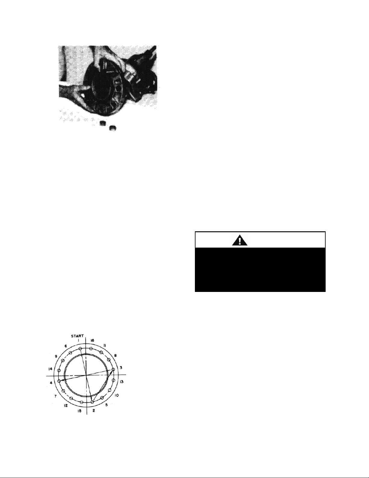
41
Safety glasses should be worn.
Field Conversion (Straight to Angle
Pattern Valve)
1. Open valve at least one complete turn.
2. Remove the body bolts from valve body
using Allen Key
3. Rotate one half of the valve body 180°
making sure the lower valve seat and O ring
stay in position. Inspect the O ring for any
4. Position the adjoining flange or the pipe
to the Armgrip flange adapter and install the
remaining bolts. The two locking bolts
should be tightened first in order to position
the flange correctly.
Note: Care should be taken to ensure that
the gasket is not pinched or bent between
flanges.
5. Tighten remaining nuts evenly by
following bolting instructions, so that the
flange faces remain parallel (as shown in the
figure labeled Recommended Bolt
Tightening Procedure).
Flange bolts should be tightened to 70 ft-lbs
torque minimum to assure firm metal to
metal contact. When raised face flanges are
sued, there will be a gap between the faces
of the outer diameter.
6. Flange gaskets are not interchangeable
with other mechanical pipe couplings or
flange gaskets.
cuts or nicks and replace if necessary
4. Replace body bolts and torque evenly to
70 ft-lbs.
Flow Measurement with the valve in the
Wide Open position:
Where approximate indication of flow is
acceptable the Flo-Trex valve can be used.
Step 1. Measure and record the differential
pressure across the valve.
Probes should not be left inserted
into fittings for long periods of time as
leakage may result.
Step 2. With valve in fully open position,
locate the differential pressure on the
Performance curve, and for the given valve
size in use, read the corresponding flow rate.
Flow Measurement with the valve in the
throttled position:
Step 1. The valve stem with its grooved
rings and positioning sleeve is the flow
indicator scale for the throttled position of
the valve.
Recommended Bolt Tightening Procedure
Page 42

42
Valve Size
2-1/2
3 4 5 6 8
10
12
Number
open)
The quarter turn graduations on the sleeve,
with the scribed line on the stem provide an
approximate flow measurement.
Note: The valve is shipped in closed
position. The indicator on the plastic
sleeve is aligned with the vertical scribed
line on the stem.
Step 2. Record the size of the valve and
stem position using the flow indicator scale.
Calculate the percentage of valve opening
based on the number of rings at the fully
open position.
Step 5. Locate the differential pressure
determined for the valve in the throttled
position on the Flo-Trex Performance
Curve. Determine the flow rate for the
given valve size at this differential pressure.
of Rings
(valve fully
5 5 6 9 10 12 18 28
Step 3. Measure and record the differential
pressure across the valve in the throttled
position.
Step 4. Locate percentage of valve opening
on the flow characteristic curve. For the
given valve, record the percentage of
maximum flow rate.
Step 6. Calculate the flow rate of the valve
in the throttled position by multiplying the
flow rate (Step 5) by the percentage of
maximum flow rate (Step 4).
Example:
Valve size: 4 in.
Differential pressure is 5.4 ft
Number of open rings is 3.
From the table, the number of rings for the 4
in valve fully open is 6. Divide open rings
by total, 3/6 = 50% throttled
From the Flo-Trex performance curve, a 4
in. valve with 5.4 ft of pressure drop
represents a flow of 400 Usgpm
Page 43

43
100
34) x (400
100
34) x (25.2
From the flow characteristic curve, a 4 inch
valve at 50% open represents 34% of
maximum flow.
The approximate flow of a 4 inch valve with
a 5.4 ft pressure drop when 50% throttled is:
=136 US gpm;
=8.57 L/s
Note: To prevent premature valve failure it
is not recommended that the valve operate in
the throttled position with more than 25 ft
pressure differential. Instead the pump
impeller should be trimmed or valves
located elsewhere in the system to partially
throttle the flow.
Operation
To assure tight shut-off, the valve must be
closed using a wrench with 25 to 30 ft-lbs of
torque.
To assure trouble free check valve operation
and shut-off operation, the valve should be
periodically opened and closed to keep valve
seat and valve disc guide stem from
accumulating system contaminants.
Repacking of Flo-Trex valve under full
system pressure
If it is necessary, the stem O ring can be
changed under full system pressure.
Safety glasses should be worn.
Step 1. Record the valve setting.
Step 2. Turn the valve stem
counterclockwise until the valve is fully
open and will not turn any further. Torque
to a maximum of 45 ft-lbs. This will ensure
good metal to metal contact and minimal
leakage.
Step 3. The valve bonnet may now be
removed. There may be a slight leakage, as
the metal to metal backseating does not
provide a drip-tight seal.
Step 4. Clean exposed portion of valve stem
being careful not to leave scratches.
Step 5. Remove and replace the O ring
gasket.
Step 6. Install the valve bonnet.
Step 7. Tightening the valve bonnet is
necessary to stop any leaks.
Step 8. Open valve to balance set point as
recorded in Step 1.
Note: On valve sizes of 2-1/2 inch and 3
inch, the full open position is 5 turns, though
the valve will open to 5-1/2 turns which is
just back of seating of valve.
Seat Replacement:
Step 1. Drain the system and remove valve
from piping.
Step 2. Remove the body bolts from the
body using an Allen Key.
Step 3. Remove seat and O Ring. O rings
are not used on valves of 8 inches or larger.
Step 4. Inspect and clean O ring cavity and
install new O ring and seat. Valve disc stem
should be inspected and replaced if worn.
Valve stem O ring should be replaced at this
time as discussed under Repacking of FloTrex section.
Page 44
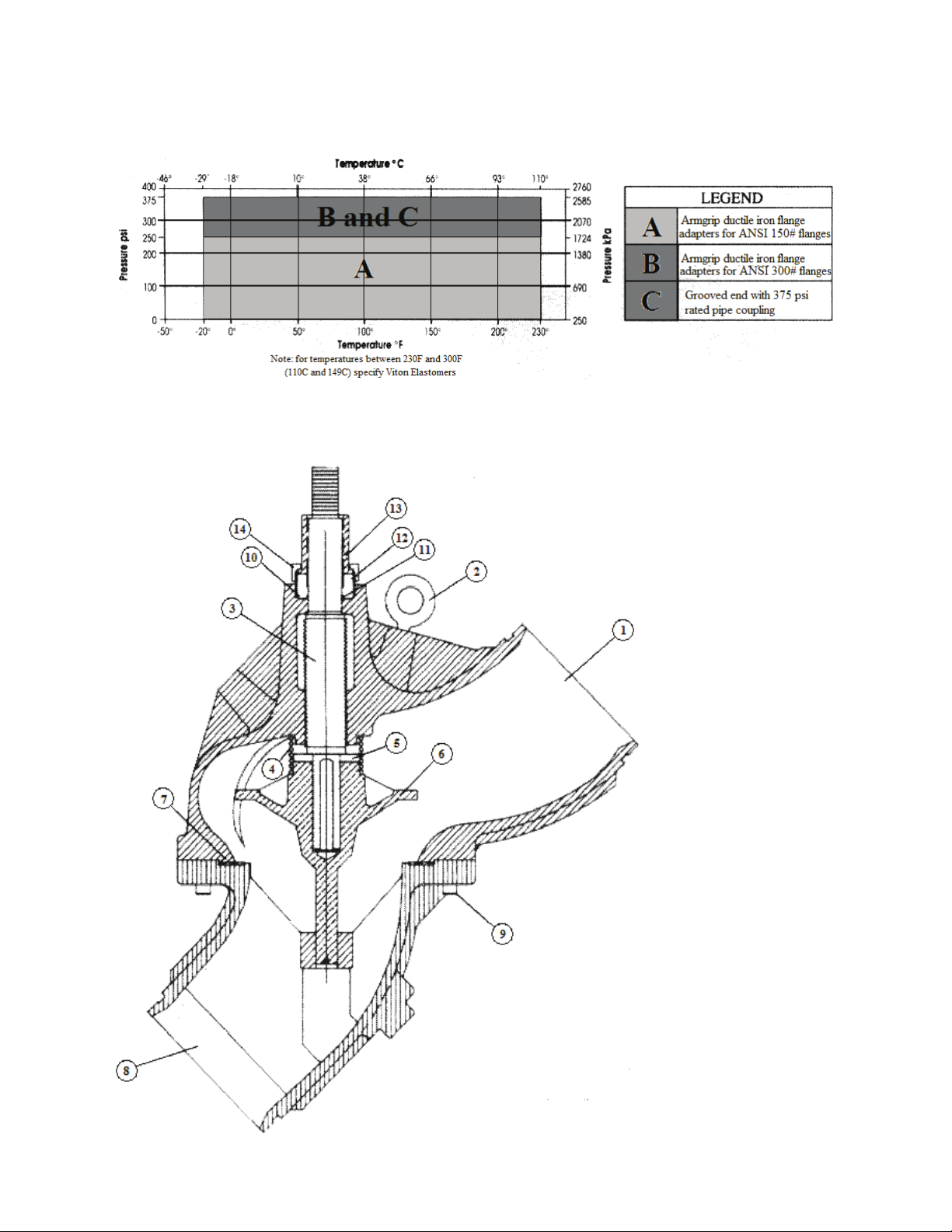
44
Pressure-Temperature Limits:
Flo-Trex Cross Section
1. Body Main
2. Eye Bolt
3. Shaft
4. Spring
5. Spacer
6. Disc
7. Seat
8. O ring body
9. Body Suction
10. Capscrew
12. O ring
13 Bonnet
14 Sleeve
Page 45
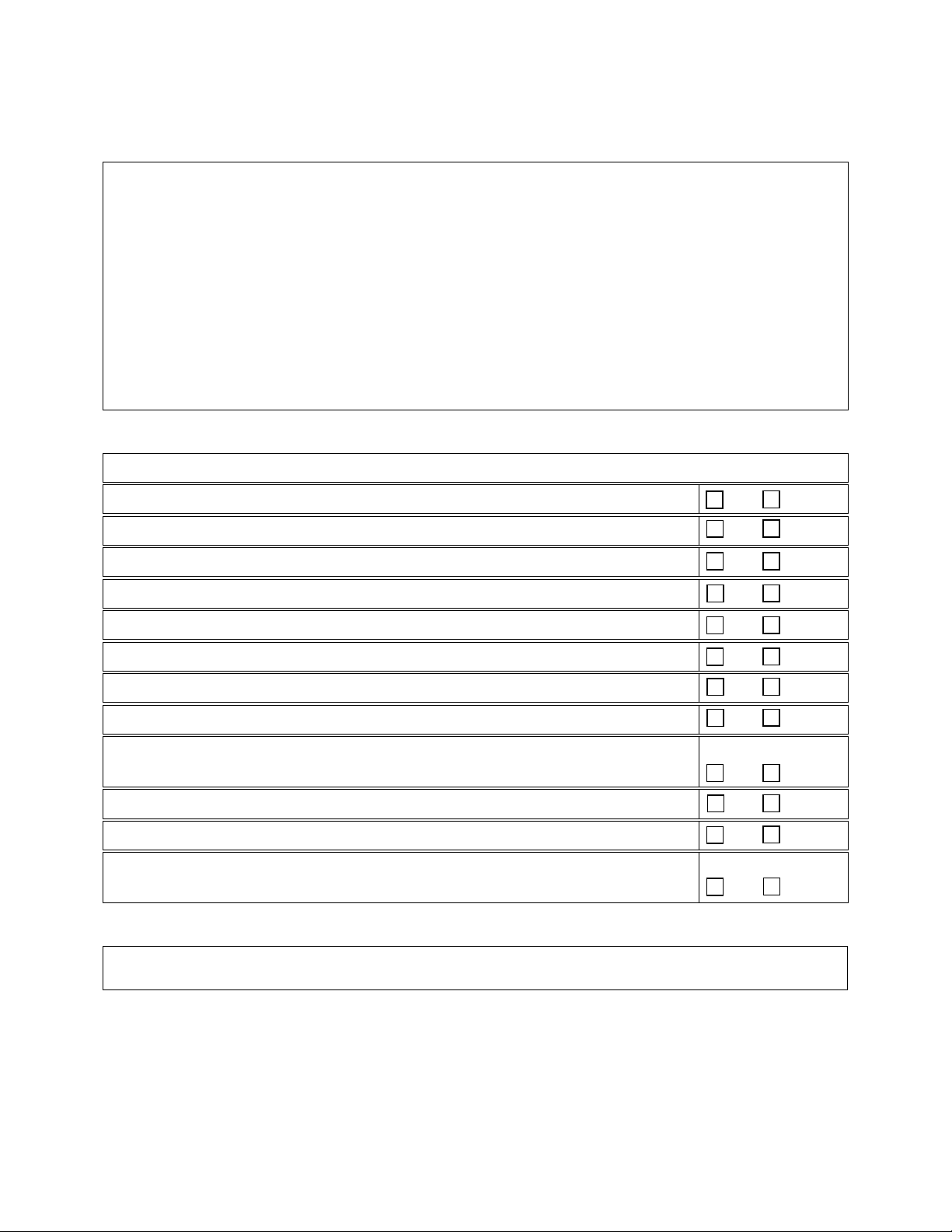
45
LC Series Startup Form
Address:______________________________________________________________________
______________________________________________________________________________
Model Number:_________________________________________________________________
Serial Number:_____________________________________________
Tag:_______________
Startup Contractor:______________________________________________________________
Address:______________________________________________________________________
_______________________________________________________
Phone:______________
Installing contractor should verify the following items.
1. Is there any visible shipping damage?
Yes No
2. Is the unit level?
Yes No
3. Are the unit clearances adequate for service and operation?
Yes No
4. Do all access doors open freely and are the handles operational?
Yes No
5. Have all shipping braces been removed?
Yes No
6. Have all electrical connections been tested for tightness?
Yes No
7. Does the electrical service correspond to the unit nameplate?
Yes No
8. On 208/230V units, has transformer tap been checked?
Yes No
9. Has overcurrent protection been installed to match the unit nameplate
requirement?
Yes No
10. Have all set screws on the fans been tightened?
Yes No
11. Do all fans rotate freely?
Yes No
12. Does the field water piping to the unit appear to be correct per design
parameters?
Yes No
Job Name:_______________________________________________
Date:______________
Pre Startup Checklist
Ambient Temperature
Ambient Dry Bulb Temperature ________°F
Ambient Wet Bulb Temperature ________°F
Page 46

46
1. Has the entire system been flushed and pressure checked?
Yes No
2. Have isolation valves to the chiller been installed?
Yes No
3. Has the entire system been filled with fluid?
Yes No
4. Has air been bled from the heat exchangers and piping?
Yes No
5. Is there a minimum load of 25% of the design load?
Yes No
6. Has the water piping been insulated?
Yes No
7. Is the glycol the proper type and concentration (N/A if water)?
Yes No
Air-Cooled Condenser
Evaporative-Cooled Condenser
Low Ambient Control
Condenser Safety Check
No Water Leaks
Water Flow ________ gpm
Chilled Water In Temperature ________°F
Chilled Water Out Temperature ________°F
Check Rotation
Head
Suction
Crankcase
1 2 3 4
Water/Glycol System
8. What is the freeze point of the glycol (N/A if water)? ______________________________
Chiller Configuration
Compressors/DX Cooling
Number Model # L1 L2 L3
Pressure
PSIG
Pressure
PSIG
Heater
Amps
Page 47
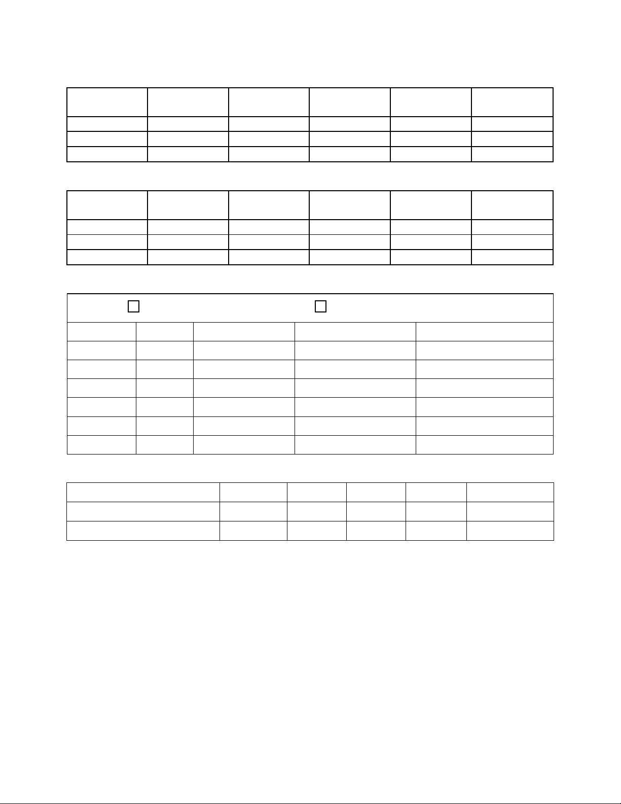
47
Refrigeration System 1 - Cooling Mode
Saturated
Temperature
Line
Temperature
Discharge
N/A
N/A
Suction
N/A
Liquid
N/A
Saturated
Temperature
Line
Temperature
Discharge
N/A
N/A
Suction
N/A
Liquid
N/A
Number
hp
L1
L2
L3
1
2
3
4
5
6
hp
L1
L2
L3
Flow (gpm)
Chiller Pump #1
Chiller Pump #2
Pressure
Refrigeration System 2 - Cooling Mode
Pressure
Condenser Fans
Alignment
Check Rotation
Sub-cooling Superheat
Sub-cooling Superheat
Nameplate Amps________
Pumping Package
Page 48

48
Entry Date
Action Taken
Name/Tel.
Maintenance Log
This log must be kept with the unit. It is the responsibility of the owner and/or
maintenance/service contractor to document any service, repair or adjustments. AAON Service
and Warranty Departments are available to advise and provide phone help for proper operation
and replacement parts. The responsibility for proper start-up, maintenance and servicing of the
equipment falls to the owner and qualified licensed technician.
Page 49

49
Literature Change History
June 2010
Revision of the IOM adding PVC and CPVC piping Caution.
April 2011
Revision of the IOM correcting the networking capabilities of the MCS Controller in Feature 13.
April 2012
Revision of the IOM adding the refrigerant charging instructions, the electronic startup form, the
index of tables and figures, and updating the table of contents.
Page 50

Page 51

Page 52

AAON
2425 South Yukon Ave.
Tulsa, OK 74107-2728
Phone: 918-583-2266
Fax: 918-583-6094
www.aaon.com
LC Series
Installation, Operation &
Maintenance
R75390 · Rev. B · 120509
(ACP 30091)
It is the intent of AAON to provide accurate and current product information. However, in the
interest of product improvement, AAON reserves the right to change pricing, specifications,
and/or design of its product without notice, obligation, or liability.
Copyright © AAON, all rights reserved throughout the world.
AAON® and AAONAIRE® are registered trademarks of AAON, Inc., Tulsa, OK.
 Loading...