

Page 1
F1 Series
Indoor Air Handing Units
Installation, Operation
& Maintenance
QUALIFIED INSTALLER
Improper installation, adjustment,
alteration, service or maintenance
can cause property damage,
personal injury or loss of life.
Installation and service must be
performed by a trained, qualified
installer. A copy of this IOM should
be kept with the unit.
These instructions are addressed
primarily to the installer; however,
useful maintenance information is
included. This manual should be kept
with the unit for future reference.
NOTICE
FOR YOUR SAFETY
Do not store or use gasoline or other
flammable vapors and liquids in the
vicinity of this or any other appliance.
If the information in this manual is not
followed exactly, a fire or explosion
may result causing property damage,
personal injury or loss of life.
Page 2

Page 3

Table of Contents
Safety .............................................................................................................................................. 6
F1 Base Model and Features Description ..................................................................................... 10
General Description ...................................................................................................................... 11
Codes and Ordinances ............................................................................................................... 11
Receiving Units ......................................................................................................................... 12
Before Beginning Installation ................................................................................................... 13
Storage ....................................................................................................................................... 13
Installation..................................................................................................................................... 14
General ...................................................................................................................................... 14
Service and Installation Clearance ............................................................................................ 14
Floor Mounted Units ................................................................................................................. 14
Suspended .................................................................................................................................. 14
Sealing ....................................................................................................................................... 15
Cooling Equipment ................................................................................................................... 15
Heating Equipment .................................................................................................................... 16
Field Wiring - MCA and MOP ................................................................................................. 16
Heat Pump ................................................................................................................................. 17
ECM Driven Fan ....................................................................................................................... 17
Reheat Coil Refrigerant Piping ................................................................................................. 18
Condensate Piping ..................................................................................................................... 20
Electrical .................................................................................................................................... 20
Thermostat ................................................................................................................................. 20
Filters ......................................................................................................................................... 20
Charging Refrigerant ................................................................................................................. 20
Evaporator Coil ......................................................................................................................... 22
Startup ........................................................................................................................................... 24
General ...................................................................................................................................... 24
Check-Out ................................................................................................................................. 24
Procedures ................................................................................................................................. 24
Electric Heat Section Procedures .............................................................................................. 25
Refrigerant Cooling Section Procedures ................................................................................... 25
Optional Equipment Procedures ................................................................................................ 25
Commissioning .......................................................................................................................... 26
Air Balancing ............................................................................................................................ 26
Water Balancing ........................................................................................................................ 26
Controls ..................................................................................................................................... 26
Operation and Maintenance .......................................................................................................... 26
General ...................................................................................................................................... 26
Maintenance Schedule ............................................................................................................... 26
Lubrication ................................................................................................................................ 27
Blower Assembly ...................................................................................................................... 27
Coils .......................................................................................................................................... 27
Heating ...................................................................................................................................... 27
Filters ......................................................................................................................................... 27
3
Page 4

Refrigerant Piping ..................................................................................................................... 28
Determining Refrigerant Line Size ........................................................................................... 29
Equivalent Line Length ............................................................................................................. 29
Predetermined Line Sizes .......................................................................................................... 32
Refrigerant Piping Diagrams ........................................................................................................ 35
Thermostat Installation and Wiring .............................................................................................. 43
F1 Series Startup Form ................................................................................................................. 53
Maintenance Log .......................................................................................................................... 56
Literature Change History............................................................................................................. 57
R58420 · Rev. B · 120509
(ACP 29902)
Page 5

Index of Table and Figures
Tables:
Table 1 - Electric Heat Minimum Circuit Ampacity .................................................................... 16
Table 2 - Electric Heat Maximum Overcurrent Protection ........................................................... 17
Table 3 - Factory Preset Air Flow................................................................................................. 17
Table 4 - Cooling Fan Speed Tap Settings ................................................................................... 17
Table 5 - Climate Settings ............................................................................................................. 18
Table 6 - Heating Fan Speed Tap Settings .................................................................................... 18
Table 7 - Acceptable Air-Cooled Refrigeration Circuit Values ................................................... 22
Table 8 - Predetermined Line Sizes for F1 and CB Series Matched Systems with Two Step R-
410A Scroll Compressors ............................................................................................................. 33
Figures:
Figure 1 - Typical Vertical and Horizontal Unit Installation Methods ......................................... 15
Figure 2 - Example Configuration of ECM Fan Taps .................................................................. 17
Figure 3 - Riser Height Versus Total Equivalent Line Length for R-410A Split System
Applications with Two Step Scroll Compressor CB-024 through CB-060 units. ........................ 34
Figure 4 - Modulating Hot Gas Reheat Piping Diagram with Air Handling Unit above
Condensing Unit. .......................................................................................................................... 35
Figure 5 - Modulating Hot Gas Reheat Piping Diagram with Air Handling Unit below
Condensing Unit ........................................................................................................................... 36
Figure 6 - Modulating Hot Gas Reheat Piping Diagram with Air Handling Unit above
Condensing Unit with Optional Accumulator .............................................................................. 37
Figure 7 - Modulating Hot Gas Reheat Piping Diagram with Air Handling Unit below
Condensing Unit with Optional Accumulator .............................................................................. 38
Figure 8 - Heat Pump Piping Diagram with Indoor Unit above Outdoor Unit............................. 39
Figure 9 - Heat Pump Piping Diagram with Outdoor Unit above Indoor Unit ............................. 40
Figure 10 - Heat Pump Piping Diagram with Modulating Hot Gas Reheat and Indoor Unit above
Outdoor Unit ................................................................................................................................. 41
Figure 11 - Heat Pump Piping with Modulating Hot Gas Reheat and Outdoor Unit above Indoor
Unit ............................................................................................................................................... 42
Figure 12 - 2 Stage Cooling with Electric Heat ............................................................................ 43
Figure 13 - 2 Stage Cooling with Heat Pump and Electric Heat .................................................. 44
Figure 14 - 2 Stage Cooling and Electric Heat with Hot Gas Reheat and Humidistat ................. 45
Figure 15 - Main Control Board for Units Equipped with Modulating Hot Gas Reheat .............. 46
Figure 16 - Field Wiring Connections for an F1 Series Air Handling Unit. ................................ 47
Figure 17 - 5kW Electric Heat ..................................................................................................... 48
Figure 18 - 10 kW Electric Heat .................................................................................................. 49
Figure 19 - 15 kW Electric Heat .................................................................................................. 50
Figure 20 - 20 kW Electric Heat ................................................................................................. 51
Figure 21 - 25 kW Electric Heat ................................................................................................. 52
5
Page 6
Safety
NOTE - Notes are intended to clarify the unit installation, operation and maintenance.
CAUTION - Caution statements are given to prevent actions that may result in
equipment damage, property damage, or personal injury.
WARNING - Warning statements are given to prevent actions that could result in
equipment damage, property damage, personal injury or death.
DANGER - Danger statements are given to prevent actions that will result in equipment
damage, property damage, severe personal injury or death.
Attention should be paid to the following statements:
ELECTRIC SHOCK, FIRE OR
EXPLOSION HAZARD
Failure to follow safety warnings
exactly could result in dangerous
operation, serious injury, death or
property damage.
Improper servicing could result in
dangerous operation, serious injury,
death or property damage.
Before servicing, disconnect all
electrical power to the unit. More
than one disconnect may be
provided.
When servicing controls, label all
wires prior to disconnecting.
Reconnect wires correctly.
Verify proper operation after
servicing. Secure all doors with
key-lock or nut and bolt.
Electric shock hazard. Before
servicing, disconnect all electrical
power to the unit, including remote
disconnects, to avoid shock hazard
or injury from rotating parts. Follow
proper Lockout-Tagout procedures.
FIRE, EXPLOSION OR CARBON
MONOXIDE POISONING HAZARD
Failure to replace proper controls
could result in fire, explosion or
carbon monoxide poisoning. Failure
to follow safety warnings exactly
could result in serious injury, death or
property damage. Do not store or use
gasoline or other flammable vapors
and liquids in the vicinity of this
appliance.
6
Page 7
During installation, testing, servicing
and troubleshooting of the equipment
it may be necessary to work with live
electrical components. Only a
qualified licensed electrician or
individual properly trained in handling
live electrical components shall
perform these tasks.
Standard NFPA-70E, an OSHA
regulation requiring an Arc Flash
Boundary to be field established and
marked for identification of where
appropriate Personal Protective
Equipment (PPE) be worn, should be
followed.
GROUNDING REQUIRED
All field installed wiring must be
completed by qualified personnel.
Field installed wiring must comply
with NEC/CEC, local and state
electrical code requirements. Failure
to follow code requirements could
result in serious injury or death.
Provide proper unit ground in
accordance with these code
requirements.
To prevent injury or death lifting
equipment capacity shall exceed unit
weight by an adequate safety factor.
Always test-lift unit not more than 24
inches high to verify proper center of
gravity lift point to avoid unit damage,
UNIT HANDLING
injury or death.
ROTATING COMPONENTS
Unit contains fans with moving parts
that can cause serious injury. Do not
open door containing fans until the
power to the unit has been
disconnected and fan wheel has
stopped rotating.
Failure to properly drain and vent
coils when not in use during freezing
temperature may result in coil and
equipment damage.
Rotation must be checked on all
MOTORS AND COMPRESSORS of
3 phase units at startup by a qualified
service technician. Scroll
compressors are directional and can
be damaged if rotated in the wrong
direction. Compressor rotation must
be checked using suction and
discharge gauges. Fan motor rotation
should be checked for proper
operation. Alterations should only be
made at the unit power connection
7
Page 8
CAUTIO
CAUTIO
Do not use oxygen, acetylene or air
in place of refrigerant and dry
nitrogen for leak testing. A violent
explosion may result causing injury or
death.
WARNING
Always use a pressure regulator,
valves and gauges to control
incoming pressures when pressure
testing a system. Excessive pressure
may cause line ruptures, equipment
damage or an explosion which may
result in injury or death.
Do not work in a closed area where
refrigerant or nitrogen gases may be
leaking. A sufficient quantity of
vapors may be present and cause
injury or death.
Do not clean DX refrigerant coils with
hot water or steam. The use of hot
water or steam on refrigerant coils
will cause high pressure inside the
coil tubing and damage to the coil.
N
To prevent damage to the unit, do not
use acidic chemical coil cleaners. Do
not use alkaline chemical coil
cleaners with a pH value greater than
8.5, after mixing, without first using
an aluminum corrosion inhibitor in the
cleaning solution.
N
Some chemical coil cleaning
compounds are caustic or toxic. Use
these substances only in accordance
with the manufacturer’s usage
instructions. Failure to follow
instructions may result in equipment
damage, injury or death.
Risk of injury from hot parts –
Disconnect all power, close all
isolation valves and allow equipment
to cool before servicing equipment
with heating coils. Hot water will
circulated even after the power is off.
8
Page 9
PVC (Polyvinyl Chloride) and CPVC
(Chlorinated Polyvinyl Chloride) are
vulnerable to attack by certain
chemicals. Polyolester (POE) oils
used with R-410A and other
refrigerants, even in trace amounts,
in a PVC or CPVC piping system will
result in stress cracking of the piping
and fittings and complete piping
system failure.
1. The unit is for indoor use only. See
General Information section for more
unit information.
2. Every unit has a unique equipment
nameplate with electrical, operational,
and unit clearance specifications.
Always refer to the unit nameplate for
specific ratings unique to the model you
have purchased.
3. READ THE ENTIRE INSTALLATION,
OPERATION AND MAINTENANCE
MANUAL. OTHER IMPORTANT
SAFETY PRECAUTIONS ARE
PROVIDED THROUGHOUT THIS
MANUAL.
4. Keep this manual and all literature
safeguarded near or on the unit.
9
Page 10
F1
Series and
Generation
F1 Base Model and Features Description
A
-
Rev.
BASE MODEL
SERIES AND GENERATION
F1
REVISION
A = Design Sequence
UNIT SIZE
024 = 24 MBtu/h (2 ton)
036 = 36 MBtu/h (3 ton)
048 = 48 MBtu/h (4 ton)
060 = 60 MBtu/h (5 ton)
VOLTAGE
1 = 208-230V/1Φ/60Hz
C = 115V/1Φ/60Hz
APPLICATION
V = Vertical Position (Up-flow)
M = Multi-Position (Up-flow or Horizontal)
HEATING
0 = No Heat
A = 5 kW
B = 10 kW
C = 15 kW
D = 20 kW
E = 25 kW
G = Hot Water Heating
H = Hot Water Heating - No Cooling
FEATURE 1: MOTORS
A = ECM - 1/2 hp
B = ECM - 3/4 hp
C = ECM - 1.0 hp
FEATURE 2: FILTERS
0 = Standard - 1” Fiberglass
060
-
Unit
Size
1
-
Voltage App. Heat Mtrs Filters Cntls Blank Refri. Blank Cabinet Special
M
-
C
-
C 0 0 0 C 000 0 0
:
FEATURE 3: CONTROLS
0 = Standard - Terminal Block
FEATURE 4: BLANK
0 = Standard
FEATURE 5: REFRIGERATION
0 = Standard - Split System Air Conditioner
C = Split System Heat Pump
D = Split System Air Conditioner + Modulating Hot
Gas Reheat
F = Split System Heat Pump + Modulating Hot Gas
Reheat
FEATURE 6: BLANK
0 = Standard
FEATURE 7: BLANK
0 = Standard
FEATURE 8: BLANK
0 = Standard
FEATURE 9: CABINET
0 = Standard - Embossed Galvanized Steel
A = Painted Cabinet Exterior
FEATURE 10: SPECIAL
0 = Standard
X = Special Price Authorization
10
Page 11
General Description
F1 Series air handling units are designed for
safe operation when installed, operated and
maintained within design specifications and
the instructions set forth in this manual. It is
necessary to follow these instructions to
avoid personal injury or damage to
equipment or property during equipment
installation, operation, start-up and
maintenance.
Improper installation, adjustment,
alteration, service or maintenance
can cause property damage,
personal injury or loss of life.
Installation and service must be
performed by a qualified installer. A
copy of this IOM should be kept with
the unit.
This equipment is protected by a
standard limited warranty under the
condition that initial startup and
maintenance is performed according
to the instructions set forth in this
manual. This manual should be read
in its entirety prior to installation and
before performing any service or
maintenance work.
These units must not be used as a
“construction heater” at anytime
during any phase of construction.
Very low return air temperatures,
harmful vapors, and misplacement of
the filters will damage the unit and its
efficiency.
Certification of Cooling Models
a. Certified for use with a residential
remote R-410A condensing unit with a
two-step compressor.
b. Certified for indoor installation only
Certification of Cooling and Reheat
Models
a. Certified for use with a residential
remote R-410A condensing unit with a
two-step compressor and hot gas
dehumidification capabilities.
b. Certified for indoor installation only
Certification of Electric Heat Models
a. Certified as an electric heating air
handling unit with a cooling coil.
b. Certified for indoor installation only.
Codes and Ordinances
F1 Series units have been tested and
certified, by ETL, in accordance with UL
Safety Standard 1995/CSA C22.2 No. 236.
System should be sized in accordance with
the American Society of Heating,
Refrigeration and Air Conditioning
Engineers Handbook.
Installation of F1 Series units must conform
to the ICC standards of the International
Mechanical Code, the International Building
Code, Installation of Air Conditioning and
Ventilating Systems Standard, NFPA 90A,
and local building, plumbing and waste
water codes. All appliances must be
electrically grounded in accordance with
local codes, or in the absence of local codes,
the current National Electric Code,
ANSI/NFPA 70 or the current Canadian
Electrical Code CSA C22.1.
Important: The United States
Environmental Protection Agency (EPA)
has issued various regulations regarding the
introduction and disposal of refrigerants in
11
Page 12
this unit. Failure to follow these regulations
CAUTIO
quip
may harm the environment and can lead to
the imposition of substantial fines. Because
regulations may vary due to passage of new
laws, AAON suggests a certified technician
perform any work done on this unit. Should
you have any questions please contact the
local office of the EPA.
WARNING
Do not, under any circumstances,
connect ductwork to any other heat
producing device such as fireplace
insert, stove, etc. Unauthorized use
of such devices may result in
property damage, fire, carbon
monoxide poisoning, explosion,
personal injury or death.
It is the responsibility of the installing
contractor to comply with codes,
ordinances, local and municipal
building laws, and manufacturer’s
instruction. Personal injury and/or
equipment damage may result if
proper procedures are not followed.
The Clean Air Act of 1990 bans the
intentional venting of refrigerant as of
July 1, 1992. Approved methods of
recovery, recycling, or reclaiming
must be followed.
N
Always wear hand and eye protection
when handling, installing, servicing,
or maintaining equipment. Sharp
edges, moving parts and fly debris
may cause personal injury and care
must be taken when working with
ment.
e
Any conflicting codes or regulations take
precedence over the information in this
manual. It is important that all installation
and service work be performed by qualified
professionals.
Receiving Units
All shipments are FOB from the factory. It
is the responsibility of the receiving party to
inspect the equipment upon arrival. Units
should be inspected for damage that may
have occurred in transit. Please do not refuse
shipments!
Check the unit model number,
specifications, electrical characteristics and
accessories to determine if they are correct.
In the event an incorrect unit is shipped, it
must be returned to the supplier and must
NOT be installed. The manufacturer
assumes no responsibility for installation of
incorrectly shipped units.
Do the following upon receipt:
1. Assure that freight carrier is in
compliance with Bill of Lading
instructions.
2. Inspect delivery before signing Bill of
Lading.
If damage is found or items are missing:
1. Note on Bill of Lading immediately.
2. Call carrier immediately to file a freight
claim and to schedule an inspection.
3. Photograph damage if possible.
12
Page 13

4. Do not move or discard damaged freight
packaging materials
5. After losses have been acknowledged by
the freight carrier, contact factory for a
repair or replacement part quote.
6. With permission of freight carrier, order
parts and/or make repairs.
7. Stay in contact with freight carrier to
ensure payment of your claim.
Nameplate should be checked to ensure the
correct model sizes and voltages have been
received to match the job requirements.
If repairs must be made to damaged goods,
then the factory should be notified before
any repair action is taken in order to protect
the warranty. Certain equipment alteration,
repair, and manipulation of equipment
without the manufacturer’s consent may
void the product warranty. Contact the
AAON Warranty Department for assistance
with handling damaged goods, repairs, and
freight claims: (903) 236-4403.
Note: Upon receipt check shipment for
items that ship loose such as filters,
thermostats and remote sensors. Consult
order and shipment documentation to
identify potential loose-shipped items.
Loose-shipped items may have been placed
inside unit cabinet for security.
Dependent upon the optional accessories
that were ordered, this equipment may
contain fragile components and delicate
electronics. Although the unit is constructed
of sturdy materials, avoid impacts and
handling methods that may damage internal
apparatus and structure of the unit. Take
care not to apply destructive force to coils,
coil and drain stub-outs, or other parts
protruding beyond the extents of the unit
casing. Always handle the unit by its
exterior casing and never by any of the
protruding parts.
Before Beginning Installation
Carefully read all instructions for the
installation prior to installing unit. Make
sure each step or procedure is understood
and any special considerations are taken into
account before starting installation.
Assemble all tools, hardware and supplies
needed to complete the installation.
Some items may need to be purchased
locally. After deciding where to install unit,
closely look the location over - both the
inside and outside of home. Note any
potential obstacles or problems that might be
encountered as noted in this manual. Choose
a more suitable location if necessary.
Storage
This equipment is not suitable for outdoor
use or storage. Never place this equipment
where it may be subjected to outdoor
conditions such as rain, snow, humidity,
extreme temperatures or corrosive
chemicals.
If installation will not occur immediately
following delivery, store equipment in a dry
protected area away from construction
traffic, and in the proper orientation as
marked on the packaging with all internal
packaging in place. Secure all loose-shipped
items.
Keep equipment free from debris, and
construction waste during installation.
Foreign materials may adversely affect unit
operation resulting in premature failures that
will not be covered by the manufacturer’s
warranty. Attach all service panels, and
cover all exposed equipment when work is
not being performed. Leave unit protected
from other construction until start-up is to
occur.
13
Page 14
CAUTIO
This unit must be stored indoors if
installation is not to occur
immediately following delivery.
Unprotected units could develop
corrosion if left exposed to the
environment. Damage resulting from
improper storage will not be covered
by the limited warranty.
N
Installation
AAON equipment has been designed for
quick and easy installation.
General
F1 Series air handling units are designed as
heating, cooling or combination units for
indoor installation only. They are designed
for R-410A refrigerant only. Flexible
connectors are required on all duct
connections to minimize air leaks.
Service and Installation Clearance
Before setting the air handling unit into
place, caution must be taken to provide
clearance for unit panels that must be
accessible for periodic service. These areas
contain the controls, safety devices,
refrigerant piping, shut-off valves and filter
access.
F1 series air handling units require a
minimum of 36 inches of service clearance
on the access panel side of the unit in order
to ensure room for removal, replacement, or
service of coils and other components if
necessary.
Note: An auxiliary (emergency) drain pan is
recommended for all applications where
there is a risk of water damage to
surrounding structure or furnishings. Refer
to local codes.
Floor Mounted Units
Make sure that the unit is level, and
mounted on a field-supplied platform with a
minimum height of 12” to allow for proper
fall on the condensate line. Other installation
provisions may be necessary according to
job specifications. F1 series air handling
units are designed for up flow and horizontal
applications only.
Suspended
The F1 series multi-position air handling
unit can be easily suspended for suspended
horizontal installations. The air handling
unit should be lifted into position,
supporting the entire unit from the bottom
throughout the lift. Suspend the air handling
unit as shown in the following Figure 1. An
auxiliary drain pan that covers the entire unit
would be required for above ceiling
installations.
The air handling unit must be installed level
and care should be taken to prevent damage
to the cabinet. Other installation provisions
may be necessary according to job
specifications and local code.
14
Page 15
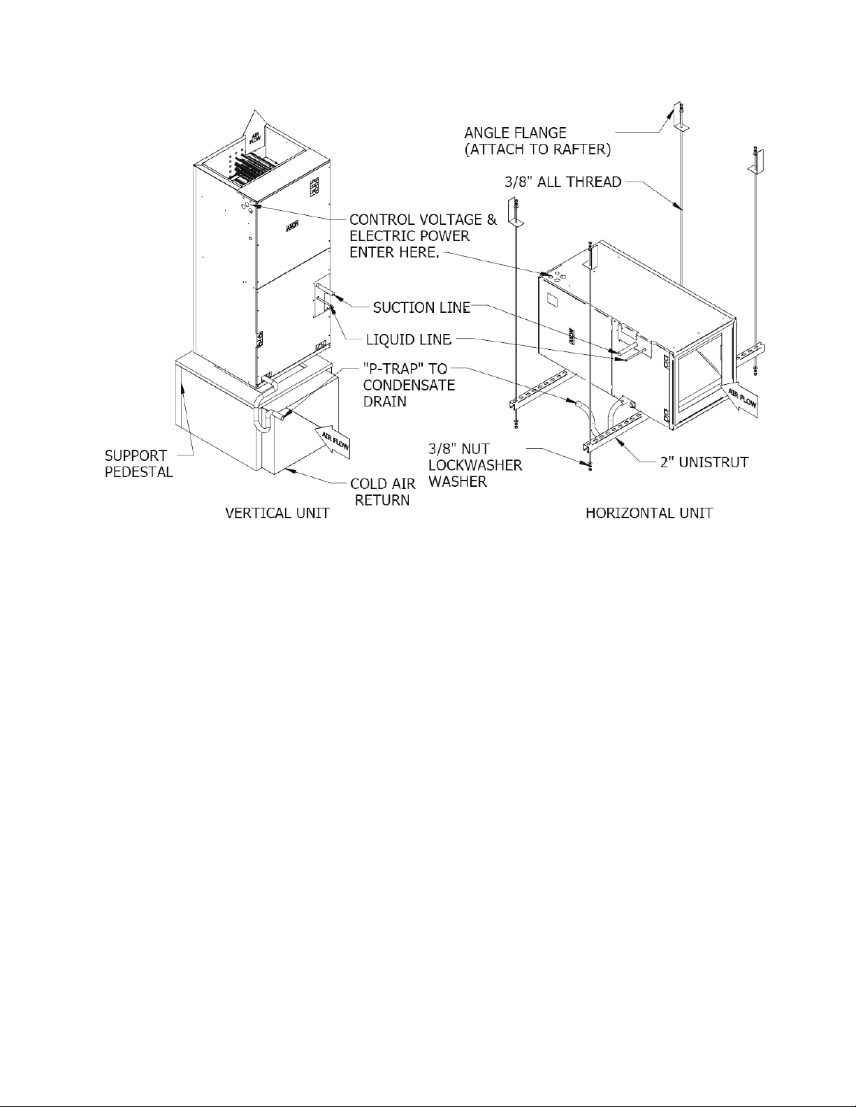
Figure 1 - Typical Vertical and Horizontal Unit Installation Methods
Sealing
It is very important to keep outside air from
infiltrating the unit cabinet. Seal all piping
penetrations with Armaflex, Permagum, or
other suitable sealant. Also seal around drain
connections, electrical connections, and
other inlets where air may enter the cabinet.
This is especially important when the unit is
installed in an unconditioned area.
Cooling Equipment
Acceptable system design and installation
will include consideration as follows:
Piping from the condensing unit to the
indoor air handling unit is the responsibility
of the installing contractor.
Only clean “ACR” tubing should be used.
Piping should conform to generally accepted
practices and codes.
Care must be taken not to cross the circuits
on reheat systems.
Once piped, the interconnecting piping and
air handling unit MUST BE evacuated to
500 microns or less; leak checked and
condenser shutoff valves opened to allow
refrigerant flow to air handling unit. Charge
unit with R-410A refrigerant to the
recommended superheat/sub-cooling in the
Charging Refrigerant section of this manual.
Make sure air handling unit thermal
expansion valve bulb is mounted with
good thermal contact on the suction line
on a horizontal section, close to the
evaporator but outside the cabinet in the
4 or 8 o’clock position and well insulated.
Lines should be fastened and supported
according to local codes.
15
Page 16
Heating Equipment
Hot Water Heating:
Water supply lines must be insulated,
properly fastened, drained and supported
according to local code requirements.
Electric Heating:
Installing Electric Heat Strip into the
Unit:
1. Remove front control panel(s) of the unit
2. Remove screws and panel covering heat
strip compartment
3. Open the heat strip kit and remove
assembly from package
4. Install strip heat into opening and secure
with 4 (four) screws
5. Install breaker assembly on bracket and
secure with breaker with 4 (four) screws
6. Make sure that breaker is in the OFF
position
7. Connect all control wires per wiring
diagram included in the unit
8. Pull and install power wires per wiring
diagram and MCA, MOP information
herein and secure all wires firmly
9. Replace the front control panel(s) of the
unit
FIELD INSTALLED WIRES SHOULD BE
SINGLE STRAND WIRES. USE OF
ROMEX WIRES IS NOT ACCEPTABLE.
Heating is accomplished by passing
electrical current through a specified amount
of resistance heaters, which will produce the
required heat. The indoor blower motor will
energize at the same time as the heaters.
Wiring to the air handling unit must be done
in accordance with local electrical codes
and/or standards. Check specified electrical
rating and install with proper wire sizes.
Also refer to wiring diagrams included with
the unit for wire sizes and circuit breaker
recommendations.
Field Wiring - MCA and MOP
Minimum Circuit Ampacity (MCA) and
Maximum Overcurrent Protection (MOP)
are necessary to correctly connect field
wired equipment.
The calculations for the MCA and MOP are
based on requirements of NFPA 70, the
National Electrical Code (NEC) and CSA
C22.1, the Canadian Electrical Code (CEC).
The MCA is the minimum wire size needed
to prevent the wiring from overheating
during operating conditions for the life of
the product. The MOP is the maximum
allowable circuit breaker size that will
properly disconnect power to the equipment
under anticipated fault conditions.
In the following tables, locate the kW of the
heater to be field installed, and then choose
the corresponding MCA and MOP values to
correctly size the wire gauge(s) and circuit
breaker(s), respectively.
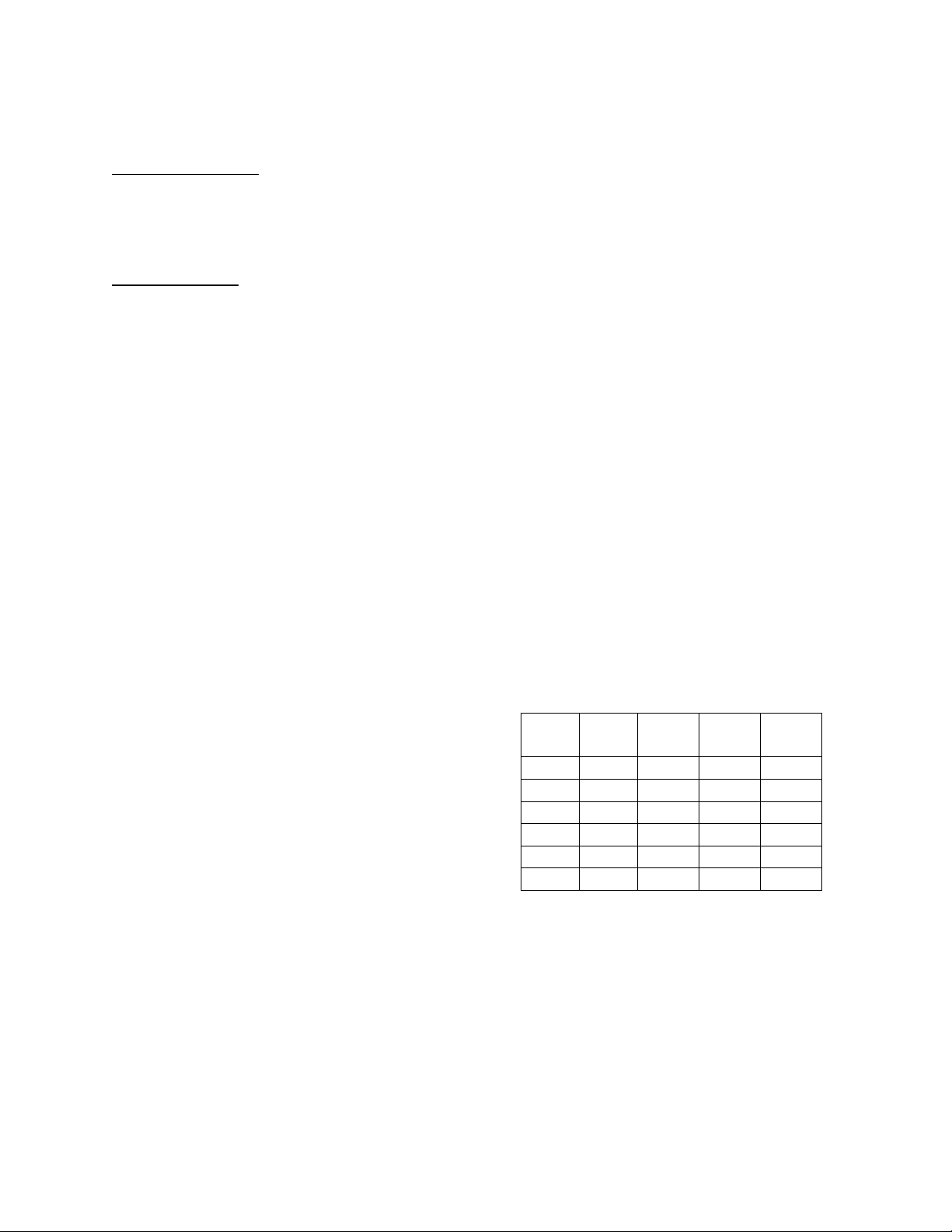
Table 1 - Electric Heat Minimum Circuit
Ampacity
230V 208V
kW kW MCA MCA MCA
5 3.75 26.0
10 7.50 52.1
15 11.25 52.1 26.0
20 15.00 52.1 52.1
25 18.75 52.1 52.1 26.0
Overcurrent protection less than that
recommended on the unit's "Specification
Sheet" could result in unnecessary fuse
failure and service call. The manufacturer
bears no responsibility for damage caused to
the equipment as a result of not using the
recommended size for the protective devices
as listed on the unit's rating plate.
Line 1 Line 2 Line
3
16
Page 17
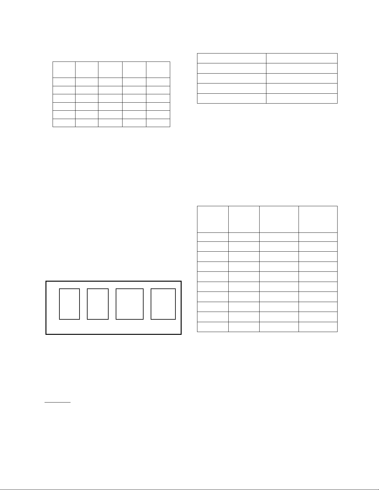
Table 2 - Electric Heat Maximum
A
A
A
Overcurrent Protection
230V 208V Line 1 Line 2 Line
3
kW kW MOP MOP MOP
5 3.75 30
10 7.50 60
15 11.25 60 30
20 15.00 60 60
25 18.75 60 60 30
Heat Pump
For heat pump equipped split system
configurations, the heat pump is the primary
heat source during a call for heat. During
operation at low ambient temperatures
where the heat pump alone cannot satisfy
the space temperature set point, electric
resistance heat elements are activated.
Below about 17°F, only the electric heat is
operable; the heat pump is not active.
ECM Driven Fan
The Electrically Commutated Motor (ECM)
has selectable fan speeds as determined by
the configuration of four pins as shown in
FIGURE 2.
----
B
C
D
HEAT COOL ADJUST DELAY
- -
- -
- -
B
C
D
- -
- -
- -
----
1
- -
+
- -
-
----
1
- -
----
B
- -
C
- -
D
- -
Figure 2 - Example Configuration of ECM
Fan Taps
Adjust the taps as desired for cooling,
dehumidification, and heating according to
the following instructions.
Cooling:
Units are preprogrammed from the factory
for a rated airflow rate of 400 cfm per ton as
shown in Table 3.
Table 3 - Factory Preset Air Flow
Model Preset cfm
F1-060 2000
F1-048 1600
F1-036 1200
F1-024 800
* Maximum total static is 2.25” w.g.
The high speed for cooling may be selected
by setting the COOL and ADJUST fan
speed taps (shown in Figure 2). The setting
combinations are shown in Table 4.
Note: On the ADJUST tap, both of the ‘1’
selections have the same effect on motor
speed.
Table 4 - Cooling Fan Speed Tap Settings
F1-060/ F1-036/
F1-048 F1-024
(cfm) (cfm)
COOL
Tap
ADJUST
Tap
2000 1200 A 1
2000 1200 D 1
1840 1150 B +
1700 1020 A 1700 1020 D 1600 1000 B 1
1380 920 C +
1360 850 B 1200 800 C 1
1020 680 C -
A signal from the thermostat, showing a
need for dehumidification, will cause the
unit to slow the fan speed in order to allow
the air moving across the coil to get colder
thereby better dehumidifying the air. Fist
stage dehumidification has a low fan speed
of 67% of the selected max speed. Second
stage dehumidification has a fan speed of
45% of the selected max speed. NOTE: The
Modulating Hot Gas Reheat option must be
selected to have a second stage of
dehumidification.
17
Page 18
In this comfort cooling application of the
ECM fan motor, heat and cool taps, A & D
have the same effect on motor speed.
Humidity Control:
Adjust the DELAY tap for humidity control
that is suitable for the climate according to
Table 5.
Table 5 - Climate Settings
CLIMATE DELAY Tap
Humid A
Sub-humid/Dry B
Semi-Arid C
Arid/Hyper-Arid D
Heating:
The fan speed for the heating cycle is
selected by adjusting the HEAT tap (see
FIGURE 2) according to TABLE 6.
Table 6 - Heating Fan Speed Tap Settings
F1-060/ F1-036/
HEAT Tap F1-048 F1-024
(cfm) (cfm)
1800 1000 A
1400 800 B
1200 600 C
1800 1000 D
ECM Fan Notes
1. Fan only = 50% of max speed
2. Dehumidifying speeds
i) First stage dehumidification =
67% of max speed
ii) Second stage dehumidification =
45% of max speed
3. Green Light will blink once per every
100 CFM
4. Dehumidification terminal is BK. There
must be a constant voltage to this
terminal, and when the voltage is
dropped then dehumidification mode
will begin.
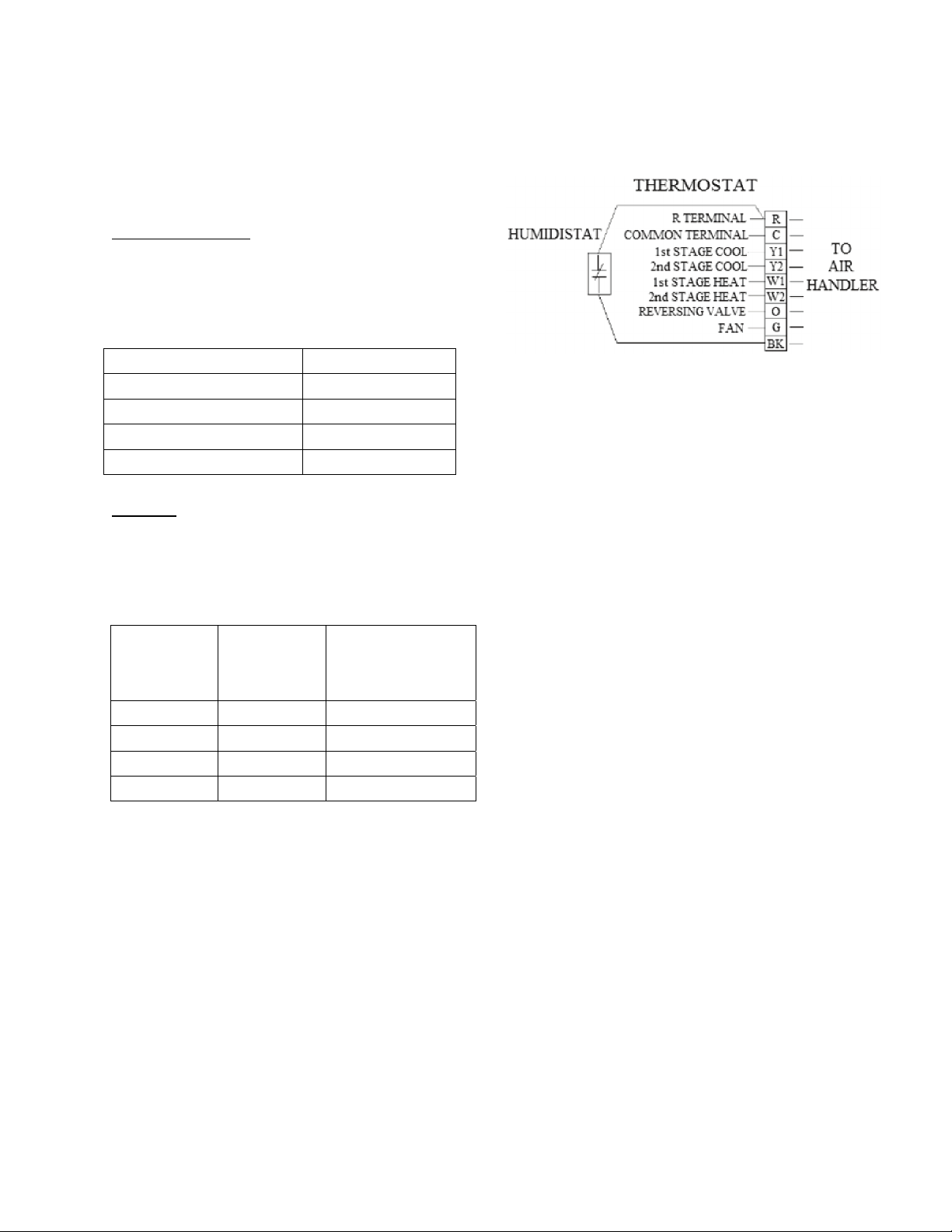
Fan wiring notes:
1. If only one stage of cooling is used then
jumper Y1 and Y2.
2. If unit is not heat pump capable then
jumper O and Y1.
3. If no humidistat is used then jumper BK
and R.
4. When only one stage of heat is used
jumper W1 and W2.
Reheat Coil Refrigerant Piping
The reheat coil is shipped already
installed on the leaving air section of the
air handling unit. A liquid receiver is
shipped loose with the unit for field
installation. (See Refrigerant Piping Section
to determine acceptable refrigerant line
size.)
1. Run a hot gas line from the outdoor unit
and connect it to the inlet of the stub-out
on the reheat coil.
a. For vertical (up-flow) units. The
inlet connection is the left stub-out
when facing the front of the unit.
Connect the hot gas line from the
outdoor unit to the left stub-out.
Connect the check valve (shipped
loose) to the right stub-out in a
direction so that the refrigerant flow
is leaving the right side of the coil.
Be sure to not block access for
18
Page 19

service of the air handling unit with
the placement of the check valve.
b. For horizontal discharge units.
Connect the hot gas line from the
outdoor unit to the upper stub-out
connection of the reheat coil.
Connect the check valve (shipped
loose) to the lower stub-out in a
direction so that the refrigerant is
leaving the bottom side of the reheat
coil. Be sure to not block access for
service of the air handling unit with
the placement of the check valve.
2. After installing the check valve, mount
the receiver (shipped loose). The
receiver tank must be mounted
horizontally for proper operation. The
receiver may be mounted on the air
handling unit or at a convenient location
near the air handling unit. Be sure to not
block access for service of the air
handling unit with the placement of the
receiver.
3. After mounting the receiver, run a liquid
line from the discharge of the check
valve to the receiver tank through a tee
connection. Run a liquid line from the
condenser, through a check valve to the
other side of the tee. Note check valve in
condenser liquid line is not used on heat
pump models. (See Refrigerant Piping
Section to determine acceptable line
size, location of components and to see a
diagram depicting the finished line
piping.)
4. After installing the receiver tank, run a
liquid line from the receiver outlet to the
TXV. (See Refrigerant Piping Section to
determine acceptable line size and to see
a diagram depicting the finished line
piping.)
5. After completing the reheat and liquid
lines, run a Suction line from the
evaporator outlet to the outdoor unit
shutoff valve (See Refrigerant Piping
Section to determine acceptable line
size.)
6. After completing the refrigerant piping
installation, install the supply air
temperature sensor (shipped loose) 18”
from the leaving air outlet from the air
handling unit.
7. After installing the supply air
temperature sensor, check that the reheat
supply air temperature setpoint is
correctly set on the control board. This
temperature should be set to the desired
space temperature when the unit is in
cooling mode. If that temperature is
unknown at the time of installation, set
the setpoint to 72°F.
The reheat system provides for “neutral”
(neither hot nor cold) air to the space so that
the unit can dehumidify the air without over
cooling or over heating the space. The
desired leaving air temperature is set on the
control board in the unit. The factory
suggests a setpoint of 72°F for most
applications; however, the setpoint is
adjustable for more specific applications or
differing comfort levels. The setpoint should
be set for the desired temperature in the
space during cooling mode. During
dehumidification mode the cooling coil
operates and the modulating valve in the
reheat system meters the amount of hot
refrigerant being directed to the reheat coil
so that the cooled and dehumidified air is
reheated, to the setpoint provided on the
control board, to a room neutral temperature.
This temperature setpoint and method of
dehumidification allows for the home to be
dehumidified even when there is not a need
for cooling in the space.
Note: Systems with the modulating hot gas
reheat option will require refrigerant to be
field added because of the additional
refrigerant components and piping
associated with the system.
19
Page 20

Condensate Piping
A drain trap must be connected to the drain
pan at the unit. Condensate connections are
provided on each side of the unit.
Condensate piping should be installed
according to local codes. The line should be
the same pipe size as the drain nipple and
should pitch downward toward the building
drain.
All cooling coils must have drain pans
equipped with “P” traps to avoid pulling air
from outside the unit back through the drain
line. All drain connection ports are sealed.
Knock out only the connection port to be
used. The trap should be located in warm
ambient spaces. An additional drain pan
may be installed under the air handling unit,
and should include a separate drain line for
overflow from the primary drain. An air
break should be used with long runs of
condensate lines.
Drain pans in any air conditioning
equipment, even when they have a built-in
slope to the drain, will have moisture present
and will require periodic cleaning to prevent
any build-up of algae or bacteria. Cleaning
of the drain pans will also prevent any
possible plugging of the drain lines, and
overflow of the pan itself. Some means to
clean out the “P” trap should be provided.
Only qualified personnel should clean drain
pans, drain lines, or the insides of
equipment.
Electrical
Check the unit data plate to make sure it
agrees with the power supply. Connect
power to the unit according to the wiring
diagram provided with the unit.
The power and control wiring may be
brought in through the holes provided on the
unit. Protect the branch circuit in accordance
with code requirements. If the control wires,
are to run inside the same conduit, use 600volt wire or as required by applicable codes.
The units must be electrically grounded in
accordance with the National Electric Code,
ANSI / UL 1995 when installed if an
external source is utilized; in Canada use
current C.S.A. Standard C22.2, No. 236,
Canadian Electric Code Part 1.
Power wiring is to the unit terminal control
board. The manufacturer has done all wiring
beyond this point. Power can be applied to
the unit after the control wiring is connected,
and startup checks are complete.
Thermostat
Units without the neutral air
dehumidification feature will operate with
most common thermostats. Units with the
neutral air dehumidification feature must use
thermostats with a normally closed (NC)
dehumidification option. The following stats
have been approved for usage with the
dehumidification feature.
Robertshaw Honeywell
9825i2
Filters
Open filter access bracket and slide correct
filter in with arrow pointing towards the
blower in the direction of airflow.
Replacement filters are 20” x 20” x 1”.
Charging Refrigerant
The unit comes with full charge based on a
25-foot line set. Charging a system in the
field must be based on determination of
liquid sub-cooling and evaporator superheat.
On a system with a thermostatic expansion
valve, liquid sub-cooling is more
representative of the charge than evaporator
superheat but both measurements must be
taken.
VisionPRO®IAQ
20
Page 21

The Clean Air Act of 1990 bans the
intentional venting of refrigerant as of
July 1, 1992. Approved methods of
recovery, recycling, or reclaiming
must be followed.
Before Charging
The unit being charged must be at or near
full load conditions before adjusting the
charge.
Units equipped with hot gas reheat must
have the hot gas reheat valves closed to get
the proper charge.
Units equipped with hot gas reheat must be
charged with the hot gas valve closed while
the unit is in cooling mode.
After adding or removing charge the system
must be allowed to stabilize, typically 10-15
minutes, before making any other
adjustments.
The type of unit and options determine the
ranges for liquid sub-cooling and evaporator
superheat. Refer to Table 7 when
determining the proper sub-cooling.
The vertical rise of the liquid line must be
known in order to adjust the sub-cooling
range for proper charge.
Checking Liquid Sub-cooling
1. Measure the temperature of the liquid
line as it leaves the condenser coil.
2. Read the gauge pressure reading of the
liquid line close to the point where the
temperature was taken. You must use liquid
line pressure, as it will vary from discharge
pressure due to condenser coil pressure
drop.
3. Convert the pressure obtained in Step 2 to
a saturated temperature using the
appropriate refrigerant temperature-pressure
chart.
4. Subtract the measured liquid line
temperature in Step 1 from the saturated
temperature in Step 3 to determine the liquid
sub-cooling.
5. Compare calculated sub-cooling to
TABLE 7 for the appropriate unit type and
options.
Checking Evaporator Superheat
1. Measure the temperature of the suction
line close to the compressor.
2. Read gauge pressure at the suction line
close to the compressor.
3. Convert the pressure obtained in Step 2 to
a saturated temperature using the
appropriate refrigerant temperature-pressure
chart.
4. Subtract the saturated temperature in Step
3 from the measured suction line
temperature in Step 1 to determine the
evaporator superheat.
5. Compare calculated superheat to TABLE
7 for the appropriate unit type and options.
Adjusting Sub-cooling and Superheat
Temperatures
The system is overcharged if:
1. the sub-cooling temperature is too high
and
2. the evaporator is fully loaded (low loads
on the evaporator result in increased subcooling) and
3. the evaporator superheat is within the
temperature range as shown in TABLE 7
(high superheat results in increased subcooling)
21
Page 22

Table 7 - Acceptable Air-Cooled
Refrigeration Circuit Values
Sub-cooling
with Hot
Gas Reheat
(°F)
Air-
Cooled
Condenser
Sub-
cooling
(°F)
12-18* 8-15** 15-22*
Superheat
(°F)
* Sub-cooling must be increased by 2°F per
20 feet of vertical liquid line rise for R410A
** Superheat will increase with long suction
line runs.
Correct an overcharged system by reducing
the amount of refrigerant in the system to
lower the sub-cooling.
Refrigerant overcharging leads to
excess refrigerant in the condenser
coils resulting in elevated compressor
discharge pressure.
DO NOT OVERCHARGE!
The system is undercharged if:
1. The superheat is too high and
2. The sub-cooling is too low.
Correct an undercharged system by adding
refrigerant to the system to reduce superheat
and raise sub-cooling.
If the sub-cooling is correct and the
superheat is too high, the TXV may need
adjustment to correct the superheat.
Elevation Limitations
See Table 8 for rise and run limitations. All
lengths listed are in equivalent feet. An
equivalent foot of the line includes the
pressure drop of all valves, components,
fittings and other pipes in the sections.
Evaporator Coil
Evaporator coils are shipped under
high pressure. Use extreme care and
follow the installation instructions
provided with the evaporator coil to
avoid personal injury.
The indoor coil is pressurized. The copper
caps must be punctured to permit a gradual
escape of the pressure prior to unsweating
those caps. Immediately couple the tubing to
the indoor unit to avoid exposing the coils to
moisture. A properly sized filter drier is
furnished in the condenser. When making
solder connections, make sure dry nitrogen
flows through the lines, when heating the
copper, to prevent oxidization inside of the
copper.
22
Page 23

°F
20
21
22
23
24
25
26
27
28
29
30
31
32
33
34
35
36
37
38
39
40
41
42
43
44
45
46
PSIG
78.3
80.0
81.8
83.6
85.4
87.2
89.1
91.0
92.9
94.9
96.8
98.8
100.9
102.9
105.0
107.1
109.2
111.4
113.6
115.8
118.1
120.3
122.7
125.0
127.4
129.8
132.2
Table 8 - R-410A Refrigerant Temperature-Pressure Chart
°F
47
48
49
50
51
52
53
54
55
56
57
58
59
60
61
62
63
64
65
66
67
68
69
70
71
72
73
PSIG
134.7
137.2
139.7
142.2
144.8
147.4
150.1
152.8
155.5
158.2
161.0
163.8
166.7
169.6
172.5
175.4
178.4
181.5
184.5
187.6
190.7
193.9
197.1
200.4
203.6
207.0
210.3
°F
74
75
76
77
78
79
80
81
82
83
84
85
86
87
88
89
90
91
92
93
94
95
96
97
98
99
100
PSIG
213.7
217.1
220.6
224.1
227.7
231.3
234.9
238.6
242.3
246.0
249.8
253.7
257.5
261.4
265.4
269.4
273.5
277.6
281.7
285.9
290.1
294.4
298.7
303.0
307.5
311.9
316.4
°F
101
102
103
104
105
106
107
108
109
110
111
112
113
114
115
116
117
118
119
120
121
122
123
124
125
126
127
PSIG
321.0
325.6
330.2
334.9
339.6
344.4
349.3
354.2
359.1
364.1
369.1
374.2
379.4
384.6
389.9
395.2
400.5
405.9
411.4
416.9
422.5
428.2
433.9
439.6
445.4
451.3
457.3
°F
128
129
130
131
132
133
134
135
136
137
138
139
140
141
142
143
144
145
146
147
148
149
150
PSIG
463.2
469.3
475.4
481.6
487.8
494.1
500.5
506.9
513.4
520.0
526.6
533.3
540.1
547.0
553.9
560.9
567.9
575.1
582.3
589.6
596.9
604.4
611.9
23
Page 24

Startup
General
ONLY QUALIFIED, AUTHORIZED
PERSONNEL SHOULD POWER ON, OR
STARTUP THIS EQUIPMENT.
Before starting up the equipment, building
construction should be complete, and startup personnel should:
Have a working knowledge of general
HVAC and mechanical commissioning
procedures and practices.
Be familiar with unit functions, features,
optional unit accessories, and all control
sequences.
Have appropriate literature on hand for
consultation.
Equipment operation during
construction is not recommended.
Construction site pollution can affect
unit operation, and seriously degrade
performance. Operation during
construction will void all
manufacturers’ warranties.
Before the structure is occupied, the
installation, and/or startup personnel must
take three essential steps:
1. Check-Out
2. Start-Up
3. Commissioning
Check-Out
Equipment should be thoroughly checked
for loose wiring, a free spinning blower
wheel and well fitting access panels. Air
handling units should not be operated
without proper ductwork and access panels
installed, except as required during start-up
and air balancing.
1. Check all electrical connections to be
sure they are tight.
2. Open all access panels, and remove all
shipping screws, or restraints.
3. Clean out any debris that may be
present.
4. Check wheel alignment, and tightness of
fan drives.
5. Check bearing locking collars if
provided and fan wheel set screws for
tightness.
6. Turn fan wheels to assure free rotation.
7. Ensure electrical supply matches the unit
nameplate.
8. Ensure condensate lines are correctly
connected.
9. Check local codes for any special
provisions.
10. Replace and/or close all access panels.
Procedures
Note: Failure to adhere to the following
start-up procedures will void all
manufacturer warranties.
Install gauges, voltmeter and ammeter
before start-up. Observe refrigerant
pressures during initial operation. Note, and
determine the cause of any excessive sound
or vibration. Follow start-up procedures
outlined below to start each piece of
equipment.
Note: Completed factory test sheets are in
the equipment literature packet shipped
inside the unit. Factory run-test readings
recorded on the test sheets may be helpful to
reference during start-up.
24
Page 25

Do not alter factory wiring. Deviation
from the supplied wiring diagram will
void all warranties, and may result in
equipment damage or personal
injury. Contact the factory with wiring
discrepancies.
Electric Heat Section Procedures
1. Perform final visual inspection.
Check all equipment ductwork and
piping to verify that all work is
complete. Improperly installed
equipment or ductwork can affect
readings.
2. Ensure that there is no construction
debris in the unit.
3. Check the unit for external damage.
4. Note all accessories installed.
5. Install a filter of the proper size and
type.
6. Check all terminal blocks, fuses, fuse
blocks, and contactors for
correctness.
7. Check all high and low voltage
wiring connections for correctness,
and tightness.
8. Check unit for correct incoming
voltage per the data plate.
9. Turn the power on.
10. Turn on the first stage of heating
Check amp draw of each element of each
stage.
Ensure blower started with electric heat.
Check for temperature rise across heating
section while all stages are on.
If temperature rise is within range, turn all
heating calls off.
Check to see that fan stops.
Refrigerant Cooling Section Procedures
1. Perform final visual inspection. Check
all equipment, ductwork and piping to
verify that all work is complete, and
equipment is properly installed and
mounted. Improperly installed
equipment or ductwork can affect
readings.
2. Perform condensing unit start-up checks
in addition to these air handling unit
checks according to the unit
manufacturer’s instructions.
3. Ensure that there is no construction
debris in the unit.
4. Check the unit for external damage.
5. Install filter of the proper size and type.
6. Ensure that drain P-trap is installed.
7. Check all terminal blocks, fuses, fuse
blocks, disconnect box, and contactors
for correctness.
8. Check all high and low voltage wiring
connections for tightness. Check unit for
correct incoming voltage per the data
plate.
9. Check the security of the locking system
on all blower bearings.
10. Turn the power on.
11. Check and record ambient temperature.
12. Check for guaranteed off timers (GOT),
and/or time delay relays (TDR).
13. Start the first step cooling circuit, and
blower circuit.
Optional Equipment Procedures
If Modulating Hot Gas Reheat is equipped,
additional installation steps are required.
1. Field installed piping is required.
2. The field supplied thermostat and
humidistat must be wired to the reheat
control as shown in the unit wiring diagram.
25
Page 26
3. Verify that the condenser hot gas valve
and reheat hot gas valve are wired as shown
in the wiring diagram.
4. Verify that the Modulating Hot Gas
Reheat system is working properly. Run for
five minutes in the reheat mode and verify
that the temperature of the supply air stream
matches the reheat temperature set point.
Commissioning
Air Balancing
High performance systems commonly have
complex air distribution and fan systems.
Unqualified personnel should not attempt to
adjust fan operation, or air circulation, as all
systems have unique operating
characteristics. Professional air balance
specialists should be employed to establish
actual operating conditions, and to configure
the air delivery system for optimal
performance.
Water Balancing
A hydronic specialist with a complete
working knowledge of water systems,
controls and operation must be employed to
properly balance the entire system.
Unqualified personnel should not attempt to
manipulate temperatures, pressures, or flow
rates, as all systems have unique operating
characteristics, and improper balancing can
result in undesirable noises and operation.
Controls
A variety of controls and electrical
accessories may be provided with the
equipment.
Identify the controls on each unit by
consulting appropriate submittal or order
documents, and operate according to the
control manufacturer’s instructions. If you
cannot locate installation, operation or
maintenance information for the specific
controls, then contact your sales
representative, or the control manufacturer
for assistance.
Operation and Maintenance
General
Immediately following unit startup, the air
conditioning system requires a maintenance
schedule to assure continued successful
operation. A maintenance program similar to
the example given below should be
scheduled for routine maintenance of this
equipment in order to provide efficient and
reliable operation for the owner.
Maintenance Schedule
One week after start-up:
Check refrigerant charge. Evacuate and
repair if leaking.
Check filters for cleanliness. Measure
pressure loss if applicable. Replace if
necessary.
Check cycling of compressors, fans and
valves. Correct unusual cycling.
Monthly:
Check cleanliness of filters, and replace if
necessary.
Check cooling coil drain pan to assure
proper drainage or correct.
Inspect evaporator and condenser coils.
Clean if dirty or obstructed in any way.
Quarterly:
Check operation of heating and cooling
sections.
Check inlet and outlet air temperatures.
Determine cause for abnormal changes.
26
Page 27
Annually:
Clean the condenser and evaporator coils
with steam or a non-corrosive cleaner.
Clean the drain line, “P” trap and condensate
pan.
Check refrigerant pressures and
temperatures every spring and correct
unusual readings.
Check heating section every fall. Check all
electrical connections for tightness and
check heater elements for indications of
overheating. Determine cause and replace
elements if necessary.
Inspect and clean unit interior at the
beginning of each heating and cooling
season and as operating conditions require.
Lubrication
All original motors and bearings are
furnished with factory lubrication. They
require no lubrication.
Blower Assembly
F1 air handling units are equipped with
highly efficient forward curved fans. The
blower wheel should be inspected
periodically and cleaned of dust and debris.
Clean blower wheels reduce electrical use,
maintain capacity and reduce stress on the
unit.
To inspect and clean the blower, set
thermostat to the “OFF” position. Turn the
electrical power to the unit to the “OFF”
position at the disconnect switch. Check set
screw for tightness.
Coils
Coils should be inspected and cleaned
annually to ensure there is no obstruction to
airflow. Dirty evaporator coils will
eventually freeze up, and often result in a
time consuming and expensive service call.
Clean filters will help to prevent dirt from
accumulating on the evaporator. The
evaporator should be cleaned annually with
a non-corrosive coil cleaning solution.
Heating
Electric:
Set thermostat in the heat mode; call for heat
to engage all electric heat strips. Verify that
electric heat operates correctly.
Heat Pump:
Set thermostat in the heat mode; call for heat
to engage the three-way valve and turn the
heat pump mode on. Verify that the heat
pump operates correctly.
Hot Water:
Set thermostat in the heat mode; call for hot
water valve to open. Verify that hot water
valve opens with call for heat.
Filters
Open filter access door. Slide filters away
from unit and inspect. Replace dirty filters
with 20” x 20” x 1” filters.
Ensure that the arrow points toward the
blower in the direction of airflow. Filters
should be checked every 30 days and
replaced or cleaned as necessary.
Equipment should never be operation
without filters.
Permanent type filters may be vacuumed
and/or washed but should not be reinstalled
until thoroughly dry. Most air filters are
marked to indicate the direction of airflow,
and this should be carefully noted when they
are being installed.
27
Page 28

Never flip a dirty filter to allow airflow
in the opposite direction.
The blower and motor bearings are
permanently lubricated and do not require
additional lubrication. It is recommended
that the owner have available at least one set
of replacement fuses of the size supplied
with the original equipment.
Important: Keep coils, fans and filters
clean.
Service
In the event the unit is not functioning
correctly and a service company is required,
only a company with service technicians
qualified and experienced in both heating
and air conditioning should be permitted to
service the systems in order to keep
warranties in effect. The service tech may
call the sales representative if assistance is
required.
Note: Service technician must provide the
model and serial number of the unit in all
correspondence with AAON.
To order parts from the AAON parts
store online go to www.aaonparts.com.
Refrigerant Piping
(See back of the manual for refrigerant
piping diagrams.)
This section is for information only
and is not intended to provide all
details required by the designer or
installer of the refrigerant piping
between the condenser or
condensing unit and the air handling
unit. AAON is not responsible for
interconnecting refrigerant piping.
Consult ASHRAE Handbook –
Refrigeration and ASME Standards.
General
Piping from the condensing unit to the air
handling unit is the responsibility of the
installing contractor.
Use only clean type “ACR” copper tubing
that has been joined with high temperature
brazing alloy.
The pipe sizes must be selected to meet the
actual installation conditions and not simply
based on the connection sizes at the
evaporator and/or condensing unit.
Condensing units are provided with in-line
shutoff valves on both the liquid and suction
lines. These should remain closed until the
system is ready for start-up after piping and
vacuuming.
Piping should conform to generally accepted
practices and codes.
Upon completion of piping connection, the
interconnecting piping and air handling unit
MUST BE evacuated to 500 microns or less;
leak checked and charged with R-410A
refrigerant.
28
Page 29

Determining Refrigerant Line Size
Line sizes must be selected to meet
actual installation conditions, not
simply based on the connection sizes
at the condensing unit or air handling
unit.
The piping between the condenser and low
side must assure:
1. Minimum pressure drop, and
2. Continuous oil return, and
3. Prevention of liquid refrigerant slugging,
or carryover
Minimizing the refrigerant line size is
favorable from an economic perspective,
reducing installation costs, and reducing the
potential for leakage. However, as pipe
diameters narrow, pressure-reducing
frictional forces increase.
Excessive suction line pressure drop causes
loss of compressor capacity and increased
power usage resulting in reduced system
efficiency. Excessive pressure drops in the
liquid line can cause the liquid refrigerant to
flash, resulting in faulty expansion valve
operation and improper system performance.
In order to operate efficiently and cost
effectively, while avoiding malfunction,
refrigeration systems must be designed to
minimize both cost and pressure loss.
The pipe sizes must be selected to meet
the actual installation conditions, and not
simply based on the connection sizes at
the evaporator and/or condensing unit.
Equivalent Line Length
All line lengths discussed in this manual,
unless specifically stated otherwise, are
Equivalent Line Lengths.
The frictional
pressure drop through valves, fittings and
accessories is determined by establishing the
equivalent length of straight pipe of the
same diameter. Always use equivalent line
lengths when calculating pressure drop.
Special piping provisions must be taken
when lines are run underground, up vertical
risers, or in excessively long line runs.
Liquid Line Sizing
When sizing the liquid line, it is important to
minimize the refrigerant charge to reduce
installation costs and improve system
reliability. This can be achieved by
minimizing the liquid line diameter.
However, reducing the pipe diameter will
increase the velocity of the liquid
refrigerant, which increases the frictional
pressure drop in the liquid line, and causes
other undesirable effects such as noise.
Maintaining the pressure in the liquid line is
critical to ensuring sufficient saturation
temperature, avoiding flashing upstream of
the TXV, and maintaining system
efficiency. Pressure losses through the liquid
line due to frictional contact, installed
accessories and vertical risers are inevitable.
Maintaining adequate sub-cooling at the
condenser to overcome these losses is the
only method to ensure that liquid refrigerant
reaches the TXV.
Liquid refrigerant traveling upwards in a
riser will lose head pressure. If the
evaporator section is below the condenser,
and the liquid line does not include risers,
the gravitational force will increase the
pressure of the liquid refrigerant. This will
allow the refrigerant to withstand greater
frictional losses without the occurrence of
flashing prior to the TXV.
A moisture-indicating sight glass may be
installed in the liquid line by special order to
indicate the occurrence of premature
flashing or moisture in the line. The sight
29
Page 30

glass should not be used to determine if the
CAUTIO
system is properly charged. Use
temperature and pressure measurements
to determine liquid sub-cooling, not the
sight glass.
Liquid Line Routing
Care should be taken with vertical risers.
When the system is shut down, gravity will
pull liquid down the vertical column, and
back to the condenser when it is below the
evaporator. This could potentially result in
compressor flooding. A check valve can be
installed in the liquid line where the liquid
column rises above the condenser to prevent
this. The liquid line is typically pitched
along with the suction line, or hot gas line,
in the direction of the compressor to
minimize the complexity of the
configuration.
Liquid Line Insulation
When the liquid line is routed through
regions where temperature losses are
expected, no insulation is required, as this
may provide additional sub-cooling to the
refrigerant. When routing the liquid line
through high temperature areas, insulation of
the line is appropriate to avoid loss of subcooling through heat gain.
Liquid Line Guidelines
In order to ensure liquid at the TXV,
frictional losses must not exceed available
sub-cooling. A commonly used guideline to
consider is a system design with pressure
losses due to friction through the line not to
exceed a corresponding 1-2°F change in
saturation temperature.
If the velocity of refrigerant in the liquid line
is too great, it could cause excessive noise or
piping erosion. The recommended
maximum velocities for liquid lines are 100
fpm from the condenser to a receiver tank
when used, to discourage fluid backup, and
300 fpm from receiver tank to the
evaporator to minimize valve induced liquid
hammer.
Liquid Line Accessories
The total length equivalent of pressure
losses through valves, elbows and fittings
must be considered when adding additional
components in the field. It is a good practice
to utilize the fewest elbows that will allow
the mating units to be successfully joined.
Suction Line Sizing
The suction line is more critical than the
liquid line from a design and construction
standpoint. More care must be taken to
ensure that adequate velocity is achieved to
return oil to the compressor at minimum
loading conditions. However, reducing the
piping diameter to increase the velocity at
minimal load can result in excessive
pressure losses, capacity reduction, and
noise at full load.
Suction Line Routing
Circuits with variable capacity scroll
compressors require suction riser
traps every 10 feet.
Pitch the suction line in the direction of flow
(about 1 ft. per 100 ft of length) to maintain
oil flow towards the compressor, and keep it
from flooding back into the evaporator.
Crankcase heaters are provided to keep any
condensed refrigerant that collects in the
compressor from causing damage or wear.
Make sure to provide support to maintain
suction line positioning, and insulate
completely between the evaporator and
condensing unit.
N
30
Page 31

It is important to consider part load
operation when sizing suction lines. At
minimum capacity, refrigerant velocity may
not be adequate to return oil up the vertical
riser. Decreasing the diameter of the vertical
riser will increase the velocity, but also the
frictional loss.
A double suction riser can be applied in this
situation. The double suction riser is
designed to return oil at minimum load
while not incurring excessive frictional
losses at full load. The double suction riser
consists of a small diameter riser in parallel
with a larger diameter riser, and a trap at the
base of the large riser. At minimum
capacity, refrigerant velocity is not sufficient
to carry oil up both risers, and it collects in
the trap, effectively closing off the larger
diameter riser, and diverting refrigerant up
the small riser where velocity of the
refrigerant is sufficient to maintain oil flow.
At full load, the mass flow clears the trap of
oil, and refrigerant is carried through both
risers. The smaller diameter pipe should be
sized to return oil at minimum load, while
the larger diameter pipe should be sized so
that flow through both pipes provides
acceptable pressure drop at full load.
Suction Line Insulation
The entire suction line should be insulated.
This prevents condensation from forming on
the line, and reduces any potential loss in
capacity associated with heat gain.
Suction Line Guidelines
For proper performance, suction line
velocities less than a 4000 fpm maximum
are recommended. The minimum velocity
required to return oil is dependent on the
pipe diameter; however, a general guideline
of 1000 fpm minimum may be applied.
In a fashion similar to the liquid line, a
common guideline to consider is a system
design with pressure losses due to friction
through the line not to exceed a
corresponding 1-2°F change in saturation
temperature.
At points where small pipe size can be used
to provide sufficient velocity to return oil in
vertical risers at part loads, greater pressure
losses are incurred at full loads. This can be
compensated for by over sizing the
horizontal runs and vertical drop sections.
This will however require additional
refrigerant charge.
If the job requirements specify suction
accumulators, they must be separately
purchased and installed.
Hot Gas Reheat
The AAON modulating hot gas reheat
system diverts hot discharge gas from the
condenser to the air handling unit through
the hot gas line. Field piping between the
condensing unit and the air handling unit
is required.
The line delivers the hot discharge gas to the
reheat coil and/or the hot gas bypass valve,
so it is sized as a discharge line.
Discharge lines should be sized to ensure
adequate velocity of refrigerant to ensure oil
return, avoid excessive noise associated with
velocities that are too high, and to minimize
efficiency losses associated with friction.
Pitch the hot gas line in the direction of flow
for oil return.
When installing hot gas reheat risers, a drip
leg must be provided at the lowest point in
the system. The drip leg must be vertical, its
diameter should be the same as the diameter
of the riser, and it should be 1 foot long. Run
a drip line, using 1/8 inch capillary tube, 10
feet in length, from the drip leg to the
31
Page 32

suction line. Connect the drip line a
minimum of 1-inch above the bottom of the
drain leg.
Insulate the entire length of the hot gas line
with a minimum 1-inch thick Armaflex
insulation.
Hot Gas Reheat Guidelines
Maintain velocities below a maximum of
3500 fpm. A general minimum velocity
guideline is 2000 fpm.
Predetermined Line Sizes
To aid in line sizing and selection, AAON
has predetermined line sizes for the liquid
and suction lines in comfort cooling
applications.
In order to generate this information, the
following cycle assumptions are made:
Saturated suction temperature = 50°F,
Saturated condensing temperature = 125°F,
Sub-cooling = 10°F, Superheat = 15°F.
The liquid lines have been chosen to
maintain velocities between 100 and 350
fpm. The suction line diameters are selected
to limit velocities to a 4000 fpm maximum,
while a minimum velocity restriction is
imposed by the ability to entrain oil up
vertical suction risers (ASHRAE Handbook
- Refrigeration).
Acceptable pressure loss criteria are applied
to each of the lines: The total equivalent
length of the liquid line available is
determined such that 3°F of liquid subcooling remain at the TXV. This includes
the pressure losses in horizontal and vertical
sections, accessories, elbows, etc.
Recall that the available sub-cooling for the
cycle is assumed as 10°F. To maintain at
least 3°F sub-cooling as a factor of safety to
avoid flashing at the TXV, we consider a
maximum pressure loss equivalent to a 7°F
change in saturation temperature. Pressure
losses in the suction line are not to exceed
2°F.
When to use predetermined line sizing
The line sizes presented are not the only
acceptable pipe diameters, they are however
appropriate for general comfort cooling
applications, and satisfy common job
requirements. Examine the conditions,
assumptions, and constraints used in the
generation of the predetermined pipe
diameters to ensure that this method is
applicable to a particular case. Do not
assume that these line sizes are appropriate
for every case. Consult ASHRAE Handbook
– Refrigeration for generally accepted
system practices.
How to use predetermined line sizing
First, read the previous section entitled
(When to use predetermined line sizing) to
decide if this method is applicable.
Next, consult Table 8 for pipe diameters.
Examine Figure 3 to determine the
acceptable line dimensions associated with
the pipe diameters determined in Table 8.
The figure is shown as total available riser
height versus total equivalent line length for
the liquid line. This curve identifies a
region of acceptable piping configuration
when the predetermined line sizes are
selected for any model in the table. A
piping configuration above the curve falls
outside the assumptions used to determine
the line size and will result in a loss of subcooling, and additional pressure losses in the
suction and hot gas bypass lines.
The total equivalent line length definition
includes the height of vertical rise, pressure
drop through elbows and accessories, and
horizontal line length, so elbows,
32
Page 33

accessories and vertical rise must be
considered when determining horizontal
length available from the total equivalent
line length.
Figure 3 is presented in terms of the liquid
line, but it assumes that the line lengths for
the suction and hot gas bypass are similar, as
these lines will commonly be routed
together to minimize the space and cost
required for split system installation.
Before using this table read the
When to Use Predetermined Line
Sizes section. Do not assume that
these line sizes are appropriate for
every case. Consult ASHRAE
Handbook – Refrigeration for
generally accepted system piping
practices. The AAON Refrigerant
Piping Calculator in Ecat32 can be
used for job specific line sizing.
Table 8 - Predetermined Line Sizes for F1 and CB Series Matched Systems with Two Step R-
410A Scroll Compressors
Model
CB-024 3/8 inch 3/4 inch 3/8 inch 3/8 inch 3/4 inch 3/8 inch
CB-036 3/8 inch 3/4 inch 3/8 inch 3/8 inch 3/4 inch 1/2 inch
CB-048 3/8 inch 7/8 inch 1/2 inch 1/2 inch 7/8 inch 1/2 inch
CB-060 3/8 inch 7/8 inch 1/2 inch 1/2 inch 7/8 inch 1/2 inch
Connection Sizes Predetermined Line Size
Liquid Suction Hot Gas Liquid Suction HGRH**
** Hot Gas Reheat line
33
Page 34

Figure 3 - Riser Height Versus Total Equivalent Line Length for R-410A Split System
Applications with Two Step Scroll Compressor CB-024 through CB-060 units.
The region of acceptable riser height is the lighter area. Select the corresponding predetermined
line size from Table 8 above.
Total Equivalent Line Length in this
figure is limited to 160 equivalent
feet.
34
Page 35

Refrigerant Piping Diagrams
Figure 4 - Modulating Hot Gas Reheat Piping Diagram with Air Handling Unit above
Condensing Unit.
35
Page 36

Figure 5 - Modulating Hot Gas Reheat Piping Diagram with Air Handling Unit below
Condensing Unit
36
Page 37

Figure 6 - Modulating Hot Gas Reheat Piping Diagram with Air Handling Unit above
Condensing Unit with Optional Accumulator
37
Page 38

Figure 7 - Modulating Hot Gas Reheat Piping Diagram with Air Handling Unit below
Condensing Unit with Optional Accumulator
38
Page 39

Figure 8 - Heat Pump Piping Diagram with Indoor Unit above Outdoor Unit
39
Page 40

40
Figure 9 - Heat Pump Piping Diagram with Outdoor Unit above Indoor Unit
Page 41

Figure 10 - Heat Pump Piping Diagram with Modulating Hot Gas Reheat and Indoor Unit above
Outdoor Unit
41
Page 42

Figure 11 - Heat Pump Piping with Modulating Hot Gas Reheat and Outdoor Unit above Indoor
Unit
42
Page 43

Thermostat Installation and Wiring
Figure 12 - 2 Stage Cooling with Electric Heat
43
Page 44

Figure 13 - 2 Stage Cooling with Heat Pump and Electric Heat
44
Page 45

Figure 14 - 2 Stage Cooling and Electric Heat with Hot Gas Reheat and Humidistat
45
Page 46
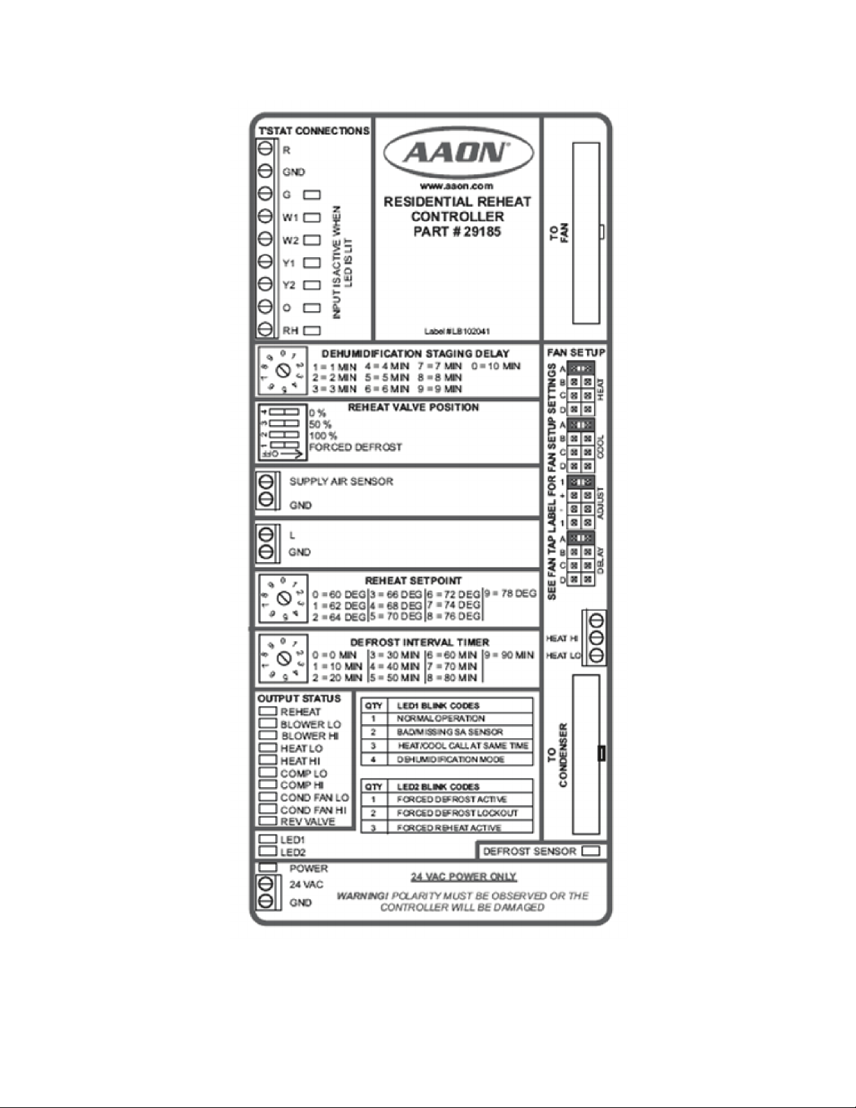
Figure 15 - Main Control Board for Units Equipped with Modulating Hot Gas Reheat
46
Page 47

Figure 16 - Field Wiring Connections for an F1 Series Air Handling Unit.
Electric heating connections are made at LVTB3.
47
Page 48

Figure 17 - 5kW Electric Heat
48
Page 49

Figure 18 - 10 kW Electric Heat
49
Page 50

Figure 19 - 15 kW Electric Heat
50
Page 51

Figure 20 - 20 kW Electric Heat
51
Page 52

Figure 21 - 25 kW Electric Heat
52
Page 53

F1 Series Startup Form
Job Name:_______________________________________________
Date:______________
Address:______________________________________________________________________
______________________________________________________________________________
Model Number:_________________________________________________________________
Serial Number:_____________________________________________ Tag:_______________
Startup Contractor:______________________________________________________________
Address:______________________________________________________________________
_______________________________________________________ Phone:______________
Pre Startup Checklist
Installing contractor should verify the following items.
1. Is there any visible shipping damage? Yes No
2. Is the unit level? Yes No
3. Are the unit clearances adequate for service and operation? Yes No
4. Do all access doors open freely and are the handles operational? Yes No
5. Have all shipping braces been removed? Yes No
6. Have all electrical connections been tested for tightness? Yes No
7. Does the electrical service correspond to the unit nameplate? Yes No
8. On 208/230V units, has transformer tap been checked? Yes No
9. Has overcurrent protection been installed to match the unit nameplate
requirement? Yes No
10. Have all set screws on the fans been tightened? Yes No
11. Do all fans rotate freely? Yes No
12. Does the field water piping to the unit appear to be correct per design
parameters? Yes No
13. Is all copper tubing isolated so that it does not rub? Yes No
14. Are air filters installed with proper orientation? Yes No
15. Have condensate drain and p-trap been connected? Yes No
Ambient Temperature
Ambient Dry Bulb Temperature ________°F
Ambient Wet Bulb Temperature ________°F
53
Page 54

Supply Fan Assembly
Alignment
Check Rotation
Nameplate Amps________
Number hp L1 L2 L3
1
Compressors/DX Cooling
Check Rotation
Number L1 L2 L3
1 - Full
Pressure
Head
PSIG
Suction
Pressure
PSIG
Crankcase
Heater
Amps
Capacity
2 Reduced
Capacity
Refrigeration System 1 Full Capacity - Cooling Mode
Pressure
Saturated
Temperature
Line
Temperature
Sub-cooling Superheat
Discharge N/A N/A
Suction N/A
Liquid N/A
Refrigeration System 1 Reduced Capacity - Cooling Mode
Pressure
Saturated
Temperature
Line
Temperature
Sub-cooling Superheat
Discharge N/A N/A
Suction N/A
Liquid N/A
Refrigeration System 1 Full Capacity - Heating Mode (Heat Pump Only)
Pressure
Saturated
Temperature
Line
Temperature
Sub-cooling Superheat
Discharge N/A N/A
Suction N/A
Liquid N/A
Refrigeration System 1 Reduced Capacity - Heating Mode (Heat Pump Only)
Pressure
Saturated
Temperature
Line
Temperature
Sub-cooling Superheat
Discharge N/A N/A
Suction N/A
Liquid N/A
54
Page 55

Unit Configuration
Water-Cooled Condenser Air-Cooled Condenser
No Water Leaks Condenser Safety Check
Water Flow ________ gpm
Water Inlet Temperature ________°F
Water Outlet Temperature ________°F
Water/Glycol System
1. Has the entire system been flushed and pressure checked? Yes No
2. Has the entire system been filled with fluid? Yes No
3. Has air been bled from the heat exchangers and piping? Yes No
4. Is the glycol the proper type and concentration (N/A if water)? Yes No
5. Is there a minimum load of 50% of the design load? Yes No
6. Has the water piping been insulated? Yes No
7. What is the freeze point of the glycol (N/A if water)? ______________________________
Air-Cooled Condenser
Alignment
Check Rotation
Nameplate Amps________
Number hp L1 L2 L3
1
Electric Heating
Stages__________ Limit Lockout Aux. Limit Lockout
Stage Amps Stage Amps
1 4
2 5
3 6
55
Page 56

Maintenance Log
This log must be kept with the unit. It is the responsibility of the owner and/or
maintenance/service contractor to document any service, repair or adjustments. AAON Service
and Warranty Departments are available to advise and provide phone help for proper operation
and replacement parts. The responsibility for proper startup, maintenance and servicing of the
equipment falls to the owner and qualified licensed technician.
Entry Date Action Taken Name/Tel.
56
Page 57

Literature Change History
November 2009
Update of the IOM formatting to match with other IOMs and adding some variable capacity
scroll compressor information.
April 2009
Update of the IOM adding the F1 Series model number description.
June 2010
Revision of the IOM adding PVC and CPVC piping Caution.
April 2012
Update of the IOM adding the electronic startup form, adding the index of tables and figures, and
updating the table of contents.
57
Page 58

Page 59

Page 60

AAON
2425 South Yukon Ave.
Tulsa, OK 74107-2728
Phone: 918-583-2266
Fax: 918-583-6094
www.aaon.com
F1 Series
Installation, Operation &
Maintenance
R58420 · Rev. B · 120509
(ACP 29902)
It is the intent of AAON to provide accurate and current product information. However, in the
interest of product improvement, AAON reserves the right to change pricing, specifications,
and/or design of its product without notice, obligation, or liability.
Copyright © AAON, all rights reserved throughout the world.
AAON® and AAONAIRE® are registered trademarks of AAON, Inc., Tulsa, OK.
 Loading...