

Page 1
CN Series
Condensing Units
If the information in this manual is not
followed exactly, a fire or explosion
may result causing property damage,
personal injury or loss of life.
WARNING
FOR YOUR SAFETY
Do not store or use gasoline or other
flammable vapors and liquids in the
vicinity of this or any other appliance.
WARNING
QUALIFIED INSTALLER
Improper installation, adjustment,
alteration, service or maintenance
can cause property damage,
personal injury or loss of life. Startup
and service must be performed by a
Factory Trained Service Technician.
A copy of this IOM should be kept
with the unit.
WARNING
Installation, Operation,
& Maintenance
Page 2

Page 3

3
Table of Contents
Safety .............................................................................................................................................. 5
CN Series Feature String Nomenclature ......................................................................................... 9
General Information ...................................................................................................................... 12
Codes and Ordinances ............................................................................................................... 12
Receiving Unit ........................................................................................................................... 12
Storage ....................................................................................................................................... 12
Wiring Diagrams ....................................................................................................................... 14
General Maintenance ................................................................................................................. 14
Installation..................................................................................................................................... 15
Unit Placement .......................................................................................................................... 15
Curb and Steel Mount Installation ............................................................................................ 15
Lifting and Handling ................................................................................................................. 16
End Flashing Installation ........................................................................................................... 16
Mounting Isolation .................................................................................................................... 18
Access Doors ............................................................................................................................. 18
Low Ambient Operation ............................................................................................................ 18
Expansion Valve Operation ...................................................................................................... 18
Determining Refrigerant Line Size ........................................................................................... 18
Liquid Line ............................................................................................................................ 19
Suction Line ........................................................................................................................... 20
Hot Gas Bypass Line ............................................................................................................. 21
Hot Gas Reheat ...................................................................................................................... 22
LAC Valve ................................................................................................................................ 23
Condenser Flooding .................................................................................................................. 24
Electrical .................................................................................................................................... 24
Startup ........................................................................................................................................... 26
Axial Flow Condenser Fans ...................................................................................................... 26
Maintenance .................................................................................................................................. 30
General ...................................................................................................................................... 30
Compressors .............................................................................................................................. 30
Refrigerant Filter Driers ............................................................................................................ 30
Adjusting Refrigerant Charge ................................................................................................... 30
Lubrication ................................................................................................................................ 34
Air-Cooled Condenser ............................................................................................................... 34
E-Coated Coil Cleaning ............................................................................................................ 34
Microchannel Coil Cleaning ..................................................................................................... 35
Service ....................................................................................................................................... 35
Replacement Parts ..................................................................................................................... 35
AAON Warranty, Service and Parts Department ...................................................................... 35
Refrigerant Piping Diagrams ........................................................................................................ 36
CN Series Startup Form ................................................................................................................ 44
Maintenance Log .......................................................................................................................... 47
Literature Change History............................................................................................................. 48
Page 4

4
Index of Tables and Figures
Tables:
Table 1 - Service Clearances......................................................................................................... 15
Table 2 - Condenser Flooding....................................................................................................... 24
Table 3 - Condenser Fan Pin Location ......................................................................................... 28
Table 4 - Condenser Fan Pin Location ......................................................................................... 28
Table 5 - Fan Assembly Bushing Torque Specifications.............................................................. 29
Table 6 - Filter Drier Maximum Pressure Drop............................................................................ 30
Table 7 - Acceptable Refrigeration Circuit Values ....................................................................... 31
Table 8 - R-410A Refrigerant Temperature-Pressure Chart ......................................................... 33
Figures:
Figure 1 - Curb Mounting with Dimensions ................................................................................. 16
Figure 2 - Steel Mounting Rail with Dimensions ......................................................................... 16
Figure 3 - Concrete Pad Mounting with Dimensions ................................................................... 16
Figure 4 - Lifting Points ................................................................................................................ 16
Figure 5 - CN Series A Cabinet Top Lifting Detail ...................................................................... 17
Figure 6 – CN Series B and C Cabinet Bottom Lifting Detial ..................................................... 17
Figure 7 - Piping Schematic of Example System using the LAC Valve. ..................................... 23
Figure 8 - Terminal Block............................................................................................................. 25
Figure 9 - Fan with the HUB on the top and RET on the bottom. ................................................ 26
Figure 10 - Bushing Mount Location............................................................................................ 27
Figure 11 - RET with Pin in Groove 4 .......................................................................................... 27
Figure 12 - Fan HUB and RET Castings ...................................................................................... 27
Figure 13 - Pitch Insert ................................................................................................................. 28
Figure 14 - A/C Only Piping, AHU Above CU ............................................................................ 36
Figure 15 - A/C Only Piping, AHU Below CU ............................................................................ 37
Figure 16 - Modulating Hot Gas Reheat Piping, AHU Above CU .............................................. 38
Figure 17 - Modulating hot gas reheat piping, AHU below CU ................................................... 39
Figure 18 - Hot gas bypass piping, AHU above CU..................................................................... 40
Figure 19 - Hot gas bypass piping, AHU below CU .................................................................... 41
Figure 20 - Modulating hot gas reheat with hot gas bypass piping, AHU above CU .................. 42
Figure 21 - Modulating hot gas reheat with hot gas bypass piping, AHU below CU .................. 43
V28960 · Rev. A · 140331
Page 5
5
Safety
ELECTRIC SHOCK, FIRE OR
EXPLOSION HAZARD
Failure to follow safety warnings
exactly could result in dangerous
operation, serious injury, death or
property damage.
Improper servicing could result in
dangerous operation, serious injury,
death, or property damage.
Before servicing, disconnect all
electrical power to the furnace.
More than one disconnect may be
provided.
When servicing controls, label all
wires prior to disconnecting.
Reconnect wires correctly.
Verify proper operation after
servicing. Secure all doors with
key-lock or nut and bolt.
WARNING
Attention should be paid to the following statements:
NOTE - Notes are intended to clarify the unit installation, operation and maintenance.
CAUTION - Caution statements are given to prevent actions that may result in
equipment damage, property damage, or personal injury.
WARNING - Warning statements are given to prevent actions that could result in
equipment damage, property damage, personal injury or death.
DANGER - Danger statements are given to prevent actions that will result in equipment
damage, property damage, severe personal injury or death.
QUALIFIED INSTALLER
Improper installation, adjustment,
alteration, service or maintenance
can cause property damage,
personal injury or loss of life. Startup
and service must be performed by a
Factory Trained Service Technician.
A copy of this IOM should be kept
with the unit.
WARNING
WHAT TO DO IF YOU SMELL GAS
Do not try to turn on unit.
Shut off main gas supply.
Do not touch any electric switch.
Do not use any phone in the
building.
Never test for gas leaks with an
open flame.
Use a gas detection soap solution
and check all gas connections
and shut off valves.
CAUTION
Page 6
6
FIRE, EXPLOSION OR CARBON
MONOXIDE POISONING HAZARD
Failure to replace proper controls
could result in fire, explosion or
carbon monoxide poisoning. Failure
to follow safety warnings exactly
could result in serious injury, death or
property damage. Do not store or use
gasoline or other flammable vapors
and liquids in the vicinity of this
appliance.
Electric shock hazard. Before
servicing, shut off all electrical power
to the unit, including remote
disconnects, to avoid shock hazard
or injury from rotating parts. Follow
proper Lockout-Tagout procedures.
WARNING
VARIABLE FREQUENCY DRIVES
Do not leave VFDs unattended in
hand mode or manual bypass.
Damage to personnel or equipment
can occur if left unattended. When in
hand mode or manual bypass mode
VFDs will not respond to controls or
alarms.
WARNING
WARNING
During installation, testing, servicing,
and troubleshooting of the equipment
it may be necessary to work with live
electrical components. Only a
qualified licensed electrician or
individual properly trained in handling
live electrical components shall
perform these tasks.
Standard NFPA-70E, an OSHA
regulation requiring an Arc Flash
Boundary to be field established and
marked for identification of where
appropriate Personal Protective
Equipment (PPE) be worn, should be
followed.
WARNING
GROUNDING REQUIRED
All field installed wiring must be
completed by qualified personnel.
Field installed wiring must comply
with NEC/CEC, local and state
electrical code requirements. Failure
to follow code requirements could
result in serious injury or death.
Provide proper unit ground in
accordance with these code
requirements.
WARNING
Electric motor over-current protection
and overload protection may be a
function of the Variable Frequency
Drive to which the motors are wired.
Never defeat the VFD motor overload
feature. The overload ampere setting
must not exceed 115% of the electric
motors FLA rating as shown on the
motor nameplate.
CAUTION
Page 7
7
PVC (Polyvinyl Chloride) and CPVC
(Chlorinated Polyvinyl Chloride) are
vulnerable to attack by certain
chemicals. Polyolester (POE) oils
used with R-410A and other
refrigerants, even in trace amounts,
in a PVC or CPVC piping system will
result in stress cracking of the piping
and fittings and complete piping
system failure.
CAUTION
UNIT HANDLING
To prevent injury or death lifting
equipment capacity shall exceed unit
weight by an adequate safety factor.
Always test-lift unit not more than 24
inches high to verify proper center of
gravity lift point to avoid unit damage,
injury or death.
WARNING
Door compartments containing
hazardous voltage or rotating parts
are equipped with door latches that
allow locks. Door latches are shipped
with a nut and bolt requiring tooled
access. If the shipping hardware is
not replaced with a pad lock, always
re-install the nut and bolt after closing
the door to maintain tooled access.
CAUTION
Rotation must be checked on all
MOTORS AND COMPRESSORS of
3 phase units at startup by a qualified
service technician. Scroll
compressors are directional and can
be damaged if rotated in the wrong
direction. Compressor rotation must
be checked using suction and
discharge gauges. Fan motor rotation
should be checked for proper
operation. Alterations should only be
made at the unit power connection
CAUTION
Do not use oxygen, acetylene or air
in place of refrigerant and dry
nitrogen for leak testing. A violent
explosion may result causing injury or
death.
WARNING
To prevent damage to the unit, do not
use acidic chemical coil cleaners. Do
not use alkaline chemical coil
cleaners with a pH value greater than
8.5, after mixing, without first using
an aluminum corrosion inhibitor in the
cleaning solution.
CAUTION
Page 8
8
Some chemical coil cleaning
compounds are caustic or toxic. Use
these substances only in accordance
with the manufacturer’s usage
instructions. Failure to follow
instructions may result in equipment
damage, injury or death.
WARNING
Do not clean DX refrigerant coils with
hot water or steam. The use of hot
water or steam on refrigerant coils
will cause high pressure inside the
coil tubing and damage to the coil.
CAUTION
Polyolester (POE) and Polyvinylether
(PVE) oils are two types of lubricants
used in hydrofluorocarbon (HFC)
refrigeration systems. Refer to the
compressor label for the proper
compressor lubricant type.
CAUTION
COMPRESSOR CYCLING
5 MINUTE MINIMUM OFF TIME
To prevent motor overheating
compressors must cycle off for a
minimum of 5 minutes.
5 MINUTE MINIMUM ON TIME
To maintain the proper oil level
compressors must cycle on for a
minimum of 5 minutes.
The cycle rate must not exceed 6
starts per hour.
WARNING
1. Startup and service must be performed
by a Factory Trained Service Technician
2. The unit is for outdoor use only. See
General Information section for more
information.
3. Every unit has a unique equipment
nameplate with electrical, operational,
and unit clearance specifications.
Always refer to the unit nameplate for
specific ratings unique to the model you
have purchased.
4. READ THE ENTIRE INSTALLATION,
OPERATION AND MAINTENANCE
MANUAL. OTHER IMPORTANT
SAFETY PRECAUTIONS ARE
PROVIDED THROUGHOUT THIS
MANUAL.
5. Keep this manual and all literature
safeguarded near or on the unit.
Page 9
CN Series Feature String Nomenclature
Model Options
:
Unit Feature Options
GEN
MJREV SIZE SERIES MNREV VLT A1
A2
A3
A4
A5
1 2A
2B 3A
3B 4 5
6A
6B
6C 7 8A
8B
8C
8D 9
10
11
12
13
14
15
CN
A - 055
- A - 0 - 3 - C A 0 0 E : 0 - 0 0 - E
0
- D 0 - 0 0 0 - 0 - D A 0 0 - 0 0 0 0 E 0
0
0 0 0 0 0 0 B
16
17
18
19
20
21
22
9
CN Series Feature String Nomenclature
MODEL OPTIONS
Series and Generation
CN
Major Revision
A
Unit Size
055 = 55 ton Capacity
065 = 65 ton Capacity
075 = 75 ton Capacity
090 = 90 ton Capacity
105 = 105 ton Capacity
120 = 120 ton Capacity
130 = 130 ton Capacity
140 = 140 ton Capacity
Series
A = 55-75 ton units
B = 90-105 ton units
C = 120-140 ton units
Minor Revision
0
Voltage
2 = 230V/3Φ/60Hz
3 = 460V/3Φ/60Hz
4 = 575V/3Φ/60Hz
8 = 208V/3Φ/60Hz
A1: Compressor Style
C = R-410A VFD Compatible Scroll Compressor
A2: Condenser Style
A = Air-Cooled Microchannel Condenser
A3: Configuration
0 = Standard
A4: Coating
0 = Standard
E = Polymer E-coated Condenser Coil
A5: Staging
A = 1 Variable Capacity Comp + 1 On/Off Comp
B = 2 Variable Capacity Comp + 2 On/Off Comp
E = All Variable Capacity Compressors
UNIT FEATURE OPTIONS
1: Unit Orientation
A = Vertical Condenser Discharge with End Control
Panel
2A: Refrigeration Control
0 = Standard
B = Fan Cycling
C = Adjustable Fan Cycling
D = Adjustable Compressor Lockout
K = Options B + D
M = Options C + D
2B: Blank
0 = Standard
3A: Refrigeration Options
0 = None
D = Hot Gas Bypass Non-Variable Compressors
[HGBNV]
E = Modulating Hot Gas Reheat [MHGR]
L = Options D + E
3B: Blank
0 = Standard
Page 10
CN Series Feature String Nomenclature
Model Options
:
Unit Feature Options
GEN
MJREV SIZE SERIES MNREV VLT A1
A2
A3
A4
A5
1 2A
2B 3A
3B 4 5
6A
6B
6C 7 8A
8B
8C
8D 9
10
11
12
13
14
15
CN A -
055
- A - 0 -
3 - C A 0 0 E : 0 - 0 0 - E 0
-
D 0 - 0 0 0 - 0 - D A 0 0 - 0
0
0 0 E 0 0
0 0 0 0 0 0 B
16
17
18
19
20
21
22
10
4: Refrigeration Accessories
0 = None
A = Sight Glass
B = Compressor Isolation Valves
C = Options A + B
D = Flooded Condenser 0°F Low Ambient Controls One Circuit
E = Options A + D
F = Options B + D
G = Options A + B + D
H = Flooded Condenser 0°F Low Ambient Controls Two Circuit
J = Options A + H
K = Options B + H
L = Options A + B + H
M = Flooded Condenser 0°F Low Ambient Controls Three Circuit
N = Options A + M
P = Options B + M
Q = Options A + B + M
R = Flooded Condenser 0°F Low Ambient Controls Four Circuit
S = Options A + R
T = Options B + R
U = Options A + B + R
5: Blank
0 = Standard
6A: Unit Disconnect Type
0 = Standard Single Point Power Block
A = Single Point Power Non-Fused Disconnect
6B: Disconnect Size
J = 60 amps
N = 100 amps
R = 150 amps
U = 225 amps
Z = 400 amps
3 = 600 amps
5 = 800 amps
7 = 1200 amps
6C: Blank
0 = Standard
7: Accessories
0 = None
B = Phase & Brown Out Protection
D = Suction Pressure Transducer All Refrigeration
Circuits
L = Options B + D
8A: Control Sequence
B = VAV Single Zone Unit Controller - VAV Cool +
CAV Heat
C = VAV Single Zone Unit Controller - VAV Cool +
VAV Heat
D = VAV Unit Controller - VAV Cool + VAV Heat
E = CAV Unit Controller - CAV Cool + CAV Heat
F = MUA Unit Controller - CAV Cool + CAV Heat
M = Field Installed DDC Controls by Others
N = Field Installed DDC Controls w/ Isolation Relays
P = Factory Installed DDC Controls Furnished by
Others w/ Isolation Relays (SPA)
8B: Control Supplier
0 = AAON Refrigeration System Supervisory
Controls
A = WattMaster Orion Control System
C = WattMaster Orion Control System (Main
Controller in Air Handler)
8C: Control Supplier Options
0 = Standard
8D: BMS Connection & Diagnostics
0 = Standard
9: Blank
0 = Standard
10: Blank
0 = Standard
Page 11
CN Series Feature String Nomenclature
Model Options
:
Unit Feature Options
GEN
MJREV SIZE SERIES MNREV VLT A1
A2
A3
A4
A5
1 2A
2B 3A
3B 4 5
6A
6B
6C 7 8A
8B
8C
8D 9
10
11
12
13
14
15
CN A -
055
- A - 0 -
3 - C A 0 0 E : 0 - 0 0 - E 0 - D 0 - 0 0 0 - 0 - D A 0 0 - 0
0
0 0 E 0 0
0 0 0 0 0 0 B
16
17
18
19
20
21
22
11
11: Maintenance Accessories
0 = None
A = 115VAC Convenience Outlet - Factory Wired
B = 115VAC Convenience Outlet - Field Wired
C = Service Access Lights
E = Remote Unit Start/Stop Terminals
F = Options A + C
H = Options A + E
J = Options B + C
L = Options B + E
N = Options C + E
R = Options A + C + E
U = Options B + C + E
12: Code Options
0 = Standard ETL US Listing
A = Chicago Code
B = ETL US + Canada Listing
13: Air-Cooled Condenser
H = Condenser Coil Guards + Three Phase
Condenser Fan Motor
J = Condenser Coil Guards + Three Phase Condenser
Fan Motor + VFD Controlled Condenser Fans (35°F
Low Ambient
14: Blank
0 = Standard
15: Blank
0 = Standard
16: Electrical Options
0 = Standard
17: Blank
0 = Standard
18: Blank
0 = Standard
19: Blank
0 = Standard
20: Cabinet Material
0 = Double Wall Galvanized Steel Cabinet + R-13
Foam Insulation
21: Warranty
0 = Standard Warranty
D = Extended Compressor Warranty Years 2-5
22: Paint and Special Pricing Authorization
B = Premium AAON Gray Paint Exterior
E = Premium AAON Gray Paint Exterior + Shrink
Wrap
X = SPA + Option B
1 = SPA + Option E
4 = SPA + Special Exterior Paint Color
7 = SPA + Special Exterior Paint Color + Shrink
Wrap
Page 12
12
Improper installation, adjustment,
alteration, service or maintenance
can cause property damage,
personal injury or loss of life. Startup
and service must be performed by a
Factory Trained Service Technician.
WARNING
The Clean Air Act of 1990 bans the
intentional venting of refrigerant as of
July 1, 1992. Approved methods of
recovery, recycling, or reclaiming
must be followed.
CAUTION
Coils and sheet metal surfaces
present sharp edges and care must
be taken when working with
equipment.
Failure to observe the following
instructions will result in premature
failure of your system and possible
voiding of the warranty.
WARNING
WARNING
General Information
AAON CN Series condensing units are
complete air-cooled condensing units
ranging from 55 to 140 tons of cooling
capacity. They are assembled, wired, and
tested.
Codes and Ordinances
CN Series units have been tested and
certified, by ETL, in accordance with UL
Safety Standard 1995/CSA C22.2 No. 236.
System should be sized in accordance with
the American Society of Heating,
Refrigeration and Air Conditioning
Engineers Handbook.
Installation of CN Series units must conform
to the ICC standards of the International
Mechanical Code, the International Building
Code, and local building, plumbing and
waste water codes. All appliances must be
electrically grounded in accordance with
local codes, or in the absence of local codes,
the current National Electric Code,
ANSI/NFPA 70 or the current Canadian
Electrical Code CSA C22.1.
Receiving Unit
When received, the unit should be checked
for damage that might have occurred in
transit. If damage is found it should be noted
on the carrier’s Freight Bill. A request for
inspection by carrier’s agent should be made
in writing at once. Nameplate should be
checked to ensure the correct model sizes
and voltages have been received to match
the job requirements.
Storage
If installation will not occur immediately
following delivery, store equipment in a dry
protected area away from construction
traffic and in the proper orientation as
marked on the packaging with all internal
packaging in place. Secure all loose-shipped
items.
Page 13
13
Scroll compressors are directional
and will be damaged by operation in
the wrong direction. Low pressure
switches on compressors have been
disconnected after factory testing.
Rotation should be checked by a
qualified service technician at startup
using suction and discharge pressure
gauges and any wiring alteration
should only be made at the unit
power connection.
CRANKCASE HEATER
OPERATION
Units may be equipped with
compressor crankcase heaters,
which should be energized at least
24 hours prior to cooling operation, to
clear any liquid refrigerant from the
compressors.
CAUTION
COMPRESSOR CYCLING
5 MINUTE MINIMUM OFF TIME
To prevent motor overheating
compressors must cycle off for a
minimum of 5 minutes.
5 MINUTE MINIMUM ON TIME
To maintain the proper oil level
compressors must cycle on for a
minimum of 5 minutes.
The cycle rate must not exceed 6
starts per hour.
WARNING
Rotation must be checked on all
MOTORS AND COMPRESSORS of
three phase units. All motors, to
include and not be limited to pump
motors and condenser fan motors,
should all be checked by a qualified
service technician at startup and any
wiring alteration should only be made
at the unit power connection.
Failure to observe the following instructions
will result in premature failure of your
system, and possible voiding of the
warranty.
Never turn off the main power supply to the
unit, except for complete shutdown. When
power is cut off from the unit, any
compressors using crankcase heaters cannot
prevent refrigerant migration. This means
the compressor will cool down, and liquid
refrigerant may accumulate in the
compressor. The compressor is designed to
pump refrigerant gas and damage may occur
when power is restored if liquid enters the
compressor.
Before unit operation, the main power
switch must be turned on for at least 24
hours for units with compressor crankcase
heaters. This will give the crankcase heater
time to clear any liquid accumulation out of
the compressor before it is required to run.
Never cut off the main power supply to the
unit, except for complete shutdown. Always
control the system from the building
management system, or control panel, never
at the main power supply (except for
emergency or for complete shutdown of the
system).
Scroll compressors must be on a minimum
of 5 minutes and off for a minimum of 5
minutes. The cycle rate must be no more
than 6 starts per hour.
Page 14

14
Compressor life will be seriously shortened
by reduced lubrication, and the pumping of
excessive amounts of liquid oil and liquid
refrigerant.
Wiring Diagrams
A complete set of unit specific wiring
diagrams in both ladder and point-to-point
form are laminated in plastic and located
inside the control compartment door.
General Maintenance
When the initial startup is made and on a
periodic schedule during operation, it is
necessary to perform routine service checks
on the performance of the condensing unit.
This includes reading and recording suction
pressures and checking for normal subcooling and superheat. See the air-cooled
condenser sections in this manual for
specific details.
Page 15
15
Location
Unit Size
55-140 tons
Front -
(Controls Side)
72”
Back
48”
Ends
96”
Top
Unobstructed
All roofing work should be performed
by competent roofing contractors to
avoid any possible leakage.
CAUTION
The base beneath the condenser
section is open and must be
considered when mounting on a curb.
CAUTION
Installation
Unit Placement
The AAON CN Series is designed for
outdoor applications and mounting at
ground level or on a rooftop. It must be
placed on a level and solid foundation that
has been prepared to support its weight.
The placement relative to the building air
intakes and other structures must be
carefully selected. Be sure to observe the
dimensions that are on the rating plate of the
condensing unit for operational and service
clearances.
Table 1 - Service Clearances
Condenser coils and fans must be free of any
obstructions in order to start and operate
properly with a correct amount of airflow.
For proper unit operation, the immediate
area around condenser must remain free of
debris that may be drawn in and obstruct
airflow in the condensing section.
Consideration must be given to obstruction
caused by snow accumulation when placing
the unit.
Curb and Steel Mount Installation
Make openings in the roof decking large
enough to allow for water piping, electrical
penetrations, and workspace only. Do not
make openings larger than necessary. Set the
curb to coincide with the openings. Make
sure curb is level.
Unit specific curb drawing is included with
job submittal. See SMACNA Architectural
Sheet Metal Manual for curb installation
details.
Units require rail support along all four sides
of the unit base.
When installed at ground level, a one-piece
concrete slab should be used with footings
that extend below the frost line. Care must
also be taken to protect the coil and fins
from damage due to vandalism or other
causes.
If unit is elevated a field supplied catwalk is
recommended to allow access to unit service
doors.
This unit ships with a curb gasket that is
1¼” wide and 1½” tall. It is recommended
that this or another similar gasket be used
between the curb and the unit to reduce
vibration from the unit to the building.
Page 16
16
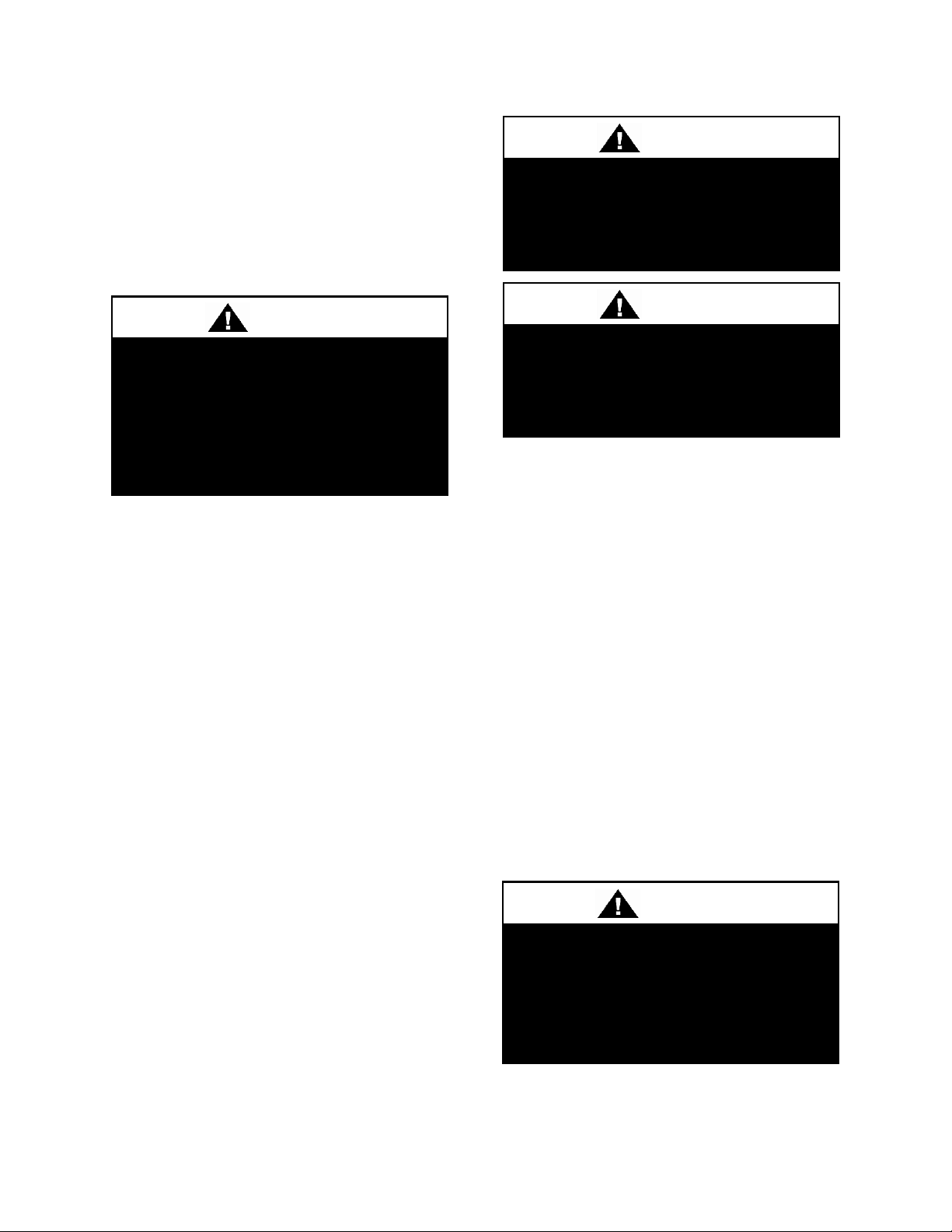
Figure 1 - Curb Mounting with Dimensions
Before lifting unit, be sure that all shipping
material has been removed from unit.
Secure hooks and cables at all lifting points/
lugs provided on the unit.
Hoist unit to a point directly above the curb
or mounting rail. Be sure that the gasket
material has been applied to the curb or
mounting rail.
Carefully lower and align unit with utility
and duct openings. Lower the unit until the
unit skirt fits around the curb. Make sure the
unit is properly seated on the curb and is
level.
Do not push, pull or lift the unit from
anything other than its base.
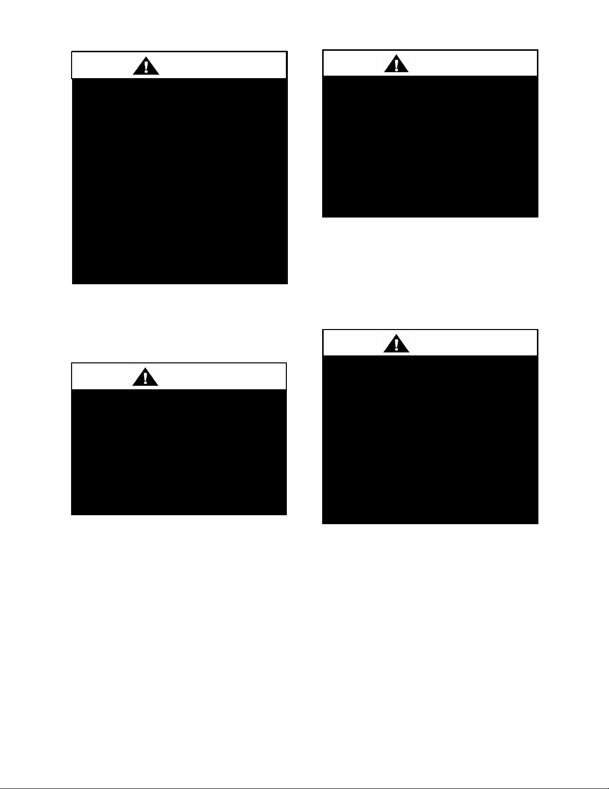
Figure 2 - Steel Mounting Rail with
Dimensions
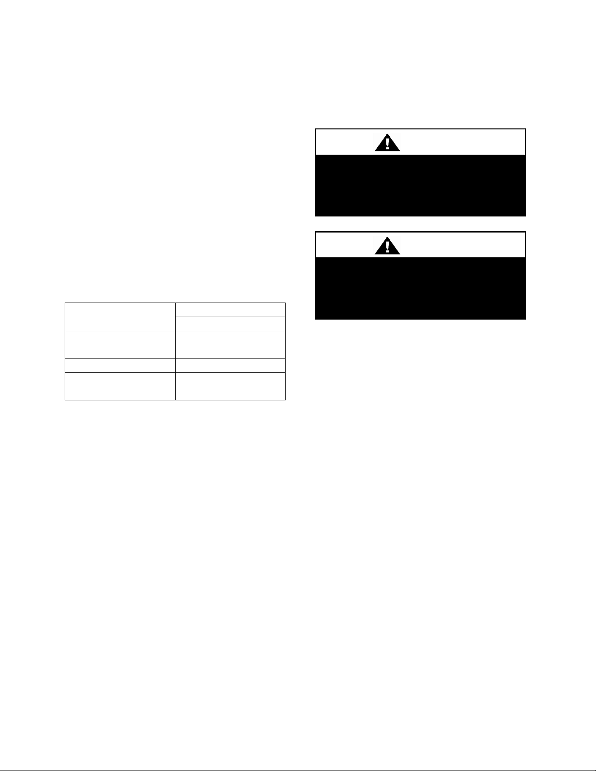
Figure 3 - Concrete Pad Mounting with
Dimensions
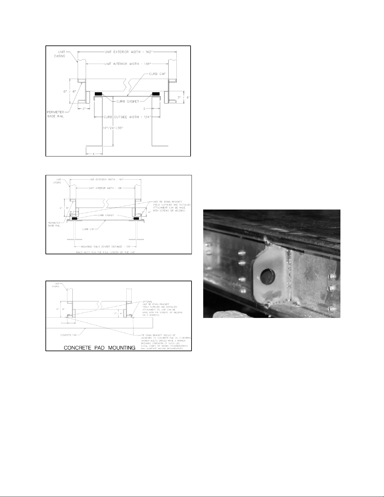
Lifting and Handling
If cables or chains are used to hoist the unit
they must be the same length and care
should be taken to prevent damage to the
cabinet. See Figure 6 for additional
information.
Figure 4 - Lifting Points
End Flashing Installation
AAON CN Series condensing units are 142”
wide, and the cabinet width will overhang
the shipping trailer on each side.
In order to secure and protect the unit during
transit the sheet metal end flashings have
been removed from the unit. The slot created
at the base of each end of the unit allows the
unit to set firmly on the trailer deck.
Sheet metal flashings are shipped loose with
the unit and once the unit is set into place
Page 17

17
the flashings must be installed on each end
of the unit to complete the finished seal at
the base. The flashings are unit specific and
designed to cover the slot at each end of the
unit to prevent water run-off into the curb.
Failure to attach and seal the end of unit
with the flashings may result in water
leakage into the curb.
Figure 5 - CN Series A Cabinet Top Lifting Detail
Figure 6 - CN Series B and C Cabinet Bottom Lifting Detial
Lifting slot locations are unit specific.
Unit must be rigged at all marked lifting points.
Page 18

18
PVC (Polyvinyl Chloride) and CPVC
(Chlorinated Polyvinyl Chloride) are
vulnerable to attack by certain
chemicals. Polyolester (POE) oils
used with R-410A and other
refrigerants, even in trace amounts,
in a PVC or CPVC piping system will
result in stress cracking of the piping
and fittings and complete piping
system failure.
CAUTION
Line sizes must be selected to meet
actual installation conditions, not
simply based on the connection sizes
at the condensing unit or air handling
unit.
CAUTION
Mounting Isolation
For roof mounted applications or anytime
vibration transmission is a factor, full
perimeter vibration isolators may be used.
Access Doors
Lockable access doors are provided to the
compressor and control compartment.
Low Ambient Operation
The AAON low ambient (condenser floodback) system is used to operate a refrigerant
system below 35°F outside air temperature.
As the ambient temperature drops, the
condenser becomes more effective therefore
lowering the head pressure. When the head
pressure gets too low, there will be
insufficient pressure to operate the
expansion valve properly. During low
ambient temperatures, it is difficult to start a
system because the refrigerant will migrate
to the cold part of the system (condenser)
and make it difficult for refrigerant to flow.
The low ambient system maintains normal
head pressure during periods of low ambient
operation by restricting liquid flow from the
condenser to the receiver, and at the same
time bypassing hot gas around the condenser
to the inlet of the receiver. This backs liquid
refrigerant up into the condenser reducing its
capacity that in turn increases the
condensing pressure. At the same time the
bypassed hot gas raises liquid pressure in the
receiver, allowing the system to operate
properly.
There are different types of low ambient
control used. The following figure shows the
type of system available on the CN Series.
Expansion Valve Operation
AAON recommends the use of electronic
expansion valves in matching air handling
units when using variable speed
compressors in CN Series condensing units.
Thermostatic expansion valves do not have
enough turn down capacity and cannot
properly manage suction superheat during
low load conditions. Electronic expansion
valves must be observed during startup
through the entire operating range of the
variable speed compressor to ensure that
suction superheat never falls below 7°F.
Insufficient suction superheat can introduce
liquid refrigerant to the compressor and
significantly reduce compressor life.
Determining Refrigerant Line Size
The piping between the condenser and low
side must ensure:
1. Minimum pressure drop, and
2. Continuous oil return, and
3. Prevention of liquid refrigerant slugging,
or carryover
Minimizing the refrigerant line size is
favorable from an economic perspective,
Page 19

19
reducing installation costs, and reducing the
potential for leakage. However, as pipe
diameters narrow, pressure-reducing
frictional forces increase.
Excessive suction line pressure drop causes
loss of compressor capacity and increased
power usage resulting in reduced system
efficiency. Excessive pressure drops in the
liquid line can cause the liquid refrigerant to
flash, resulting in faulty expansion valve
operation and improper system performance.
In order to operate efficiently and cost
effectively, while avoiding malfunction,
refrigeration systems must be designed to
minimize both cost and pressure loss.
Equivalent Line Length
All line lengths discussed in this manual,
unless specifically stated otherwise, are
Equivalent Line Lengths. The frictional
pressure drop through valves, fittings, and
accessories is determined by establishing the
equivalent length of straight pipe of the
same diameter. Always use equivalent line
lengths when calculating pressure drop.
Special piping provisions must be taken
when lines are run underground, up vertical
risers, or in excessively long line runs.
Liquid Line
When sizing the liquid line, it is important to
minimize the refrigerant charge to reduce
installation costs and improve system
reliability. This can be achieved by
minimizing the liquid line diameter.
However, reducing the pipe diameter will
increase the velocity of the liquid refrigerant
which increases the frictional pressure drop
in the liquid line, and causes other
undesirable effects such as noise.
Maintaining the pressure in the liquid line is
critical to ensuring sufficient saturation
temperature, avoiding flashing upstream of
the expansion valve, and maintaining system
efficiency. Pressure losses through the
liquid line due to frictional contact, installed
accessories, and vertical risers are
inevitable. Maintaining adequate subcooling at the condenser to overcome these
losses is the only method to ensure that
liquid refrigerant reaches the expansion
valve.
Liquid refrigerant traveling upwards in a
riser loses head pressure. If the evaporator is
below the condenser, and the liquid line
does not include risers, the gravitational
force will increase the pressure of the liquid
refrigerant. This will allow the refrigerant to
withstand greater frictional losses without
the occurrence of flashing prior to the
expansion vavle.
A moisture-indicating sight glass may be
field installed in the liquid line to indicate
the occurrence of premature flashing or
moisture in the line. The sight glass should
not be used to determine if the system is
properly charged. Use temperature and
pressure measurements to determine
liquid sub-cooling, not the sight glass.
Liquid Line Routing
Care should be taken with vertical risers.
When the system is shut down, gravity will
pull liquid down the vertical column, and
back to the condenser when it is below the
evaporator. This could potentially result in
compressor flooding. A check valve can be
installed in the liquid line where the liquid
column rises above the condenser to prevent
this. The liquid line is typically pitched
along with the suction line, or hot gas line,
to minimize the complexity of the
configuration.
Liquid Line Insulation
When the liquid line is routed through
regions where temperature losses are
expected, no insulation is required, as this
Page 20

20
Suction line must be sized in
accordance to the minimum capacity
of the variable speed compressor.
CAUTION
may provide additional sub-cooling to the
refrigerant. When routing the liquid line
through high temperature areas, insulation of
the line is appropriate to avoid loss of subcooling through heat gain.
Liquid Line Guidelines
In order to ensure liquid at the expansion
valve, frictional losses must not exceed
available sub-cooling. A commonly used
guideline to consider is a system design with
pressure losses due to friction through the
line not to exceed a corresponding 1-2°F
change in saturation temperature.
If the velocity of refrigerant in the liquid line
is too great, it could cause excessive noise or
piping erosion. The recommended
maximum velocities for liquid lines are 100
fpm from the condenser to a receiver tank to
discourage fluid backup, and 300 fpm from
receiver tank to the evaporator to minimize
valve induced liquid hammer.
Liquid Line Accessories
Liquid line shut off valves and filter driers
are factory provided. The total length
equivalent of pressure losses through valves,
elbows and fittings must be considered when
adding additional components in the field. It
is a good practice to utilize the fewest
elbows that will allow the mating units to be
successfully joined.
Suction Line
The suction line is more critical than the
liquid line from a design and construction
standpoint. More care must be taken to
ensure that adequate velocity is achieved to
return oil to the compressor at minimum
loading conditions. However, reducing the
piping diameter to increase the velocity at
minimal load can result in excessive
pressure losses, capacity reduction, and
noise at full load.
Suction Line Routing
Pitch the suction line in the direction of flow
(about 1 foot per 120 feet of length) to
maintain oil flow towards the compressor,
and keep it from flooding back into the
evaporator. Crankcase heaters may be
provided to keep any condensed refrigerant
that collects in the compressor from causing
damage or wear. Make sure to provide
support to maintain suction line positioning,
and insulate completely between the
evaporator and condensing unit.
It is important to consider part load
operation when sizing suction lines. At
minimum capacity, refrigerant velocity may
not be adequate to return oil up the vertical
riser. Decreasing the diameter of the vertical
riser will increase the velocity, but also the
frictional loss.
A double suction riser can be applied to the
situation of part load operation with a
suction riser. A double suction riser is
designed to return oil at minimum load
while not incurring excessive frictional
losses at full load. A double suction riser
consists of a small diameter riser in parallel
with a larger diameter riser, and a trap at the
base of the large riser. At minimum
capacity, refrigerant velocity is not sufficient
to carry oil up both risers, and it collects in
the trap, effectively closing off the larger
diameter riser, and diverting refrigerant up
the small riser where velocity of the
refrigerant is sufficient to maintain oil flow.
At full load, the mass flow clears the trap of
oil, and refrigerant is carried through both
risers. The smaller diameter pipe should be
Page 21

21
sized to return oil at minimum load, while
the larger diameter pipe should be sized so
that flow through both pipes provides
acceptable pressure drop at full load.
Suction Line Insulation
The entire suction line should be insulated
with a minimum 1 inch thick Armaflex
insulation. This prevents condensation from
forming on the line, and reduces any
potential loss in capacity associated with
heat gain placing additional load on the
system.
Suction Line Guidelines
For proper performance, suction line
velocities less than a 4,000 fpm maximum
are recommended. The minimum velocity
required to return oil is dependent on the
pipe diameter, however, a general guideline
of 1,000 fpm minimum may be applied.
In a fashion similar to the liquid line, a
common guideline to consider is a system
design with pressure losses due to friction
through the line not to exceed a
corresponding 1-2°F change in saturation
temperature.
At points where small pipe size can be used
to provide sufficient velocity to return oil in
vertical risers at part loads, greater pressure
losses are incurred at full loads. This can be
compensated for by over sizing the
horizontal runs and vertical drop sections.
This will however require additional
refrigerant charge.
Suction Line Accessories
If the job requirements specify suction
accumulators, they must be separately
purchased and field installed.
Hot Gas Bypass Line
Hot Gas Bypass is available for use with DX
systems that may experience low suction
pressure during the operating cycle. This
may be due to varying load conditions
associated with VAV applications or units
supplying a large percentage of outside air.
The system is designed to divert refrigerant
from the compressor discharge to the low
pressure side of the system in order to keep
the evaporator from freezing and to maintain
adequate refrigerant velocity for oil return at
minimum load.
Hot discharge gas is redirected to the
evaporator inlet via an auxiliary side
connector (ASC) to false load the evaporator
when reduced suction pressure is sensed.
Field piping between the condensing unit
and the evaporator is required.
Hot Gas Bypass Piping Considerations for
Evaporator above Condensing Unit
Pitch the hot gas bypass (HGB) line
downward in the direction of refrigerant
flow, toward the evaporator.
When installing hot gas bypass risers, an oil
drip line must be provided at the lowest
point in the system. The oil drip line must be
vertical, its diameter should be the same as
the diameter of the riser, and it should be 1
foot long. Install a sight glass in the oil drip
line for observation. Run an oil return line,
using 1/8 inch capillary tube, 10 feet in
length, from the oil drip line to the suction
line. Connect the oil return line below the
sight glass and 1 inch above the bottom of
the oil drip line.
HGB valves are adjustable. Factory HGB
valve settings will be sufficient for most
applications, but may require slight
adjustments for some applications, including
some make up air applications.
Insulate the entire length of the HGB line
with a minimum 1 inch thick Armaflex
insulation.
Page 22

22
Hot Gas Bypass Piping Considerations for
Evaporator Below Condensing Unit
The line must slope downward from the
HGB valve toward the evaporator.
Hot Gas Bypass Line Guidelines
Choose a small size line to ensure oil return,
and minimize refrigerant charge.
Maintain velocities below a maximum of
4,000 fpm. A general minimum velocity
guideline to use is approximately 1,000 fpm.
Hot Gas Reheat
The AAON modulating hot gas reheat
system diverts hot discharge gas from the
condenser to the air handling unit through
the hot gas line. Field piping between the
condensing unit and the air handler is
required.
The line delivers the hot discharge gas to the
reheat coil and/or the hot gas bypass valve,
so it is sized as a discharge line.
Discharge lines should be sized to ensure
adequate velocity of refrigerant to ensure oil
return, avoid excessive noise associated with
velocities that are too high, and to minimize
efficiency losses associated with friction.
Pitch the hot gas line in the direction of flow
for oil return.
When installing hot gas reheat risers, an oil
drip line must be provided at the lowest
point in the system. The oil drip line must be
vertical, its diameter should be the same as
the diameter of the riser, and it should be 1
foot long. Run a drip line, using 1/8 inch
capillary tube, 10 feet in length, from the oil
drip line to the suction line. Connect the oil
return line below the sight glass and 1 inch
above the bottom of the oil drip line.
Insulate the entire length of the hot gas line
with a minimum 1 inch thick Armaflex
insulation.
Hot Gas Reheat Guidelines
Maintain velocities below a maximum of
3,500 fpm. A general minimum velocity
guideline is 2,000 fpm.
Page 23

23
LAC Valve
The LAC valve is a non-adjustable three
way valve that modulates to maintain
receiver pressure. As the receiver pressure
drops below the valve setting (295 psig for
R-410A), the valve modulates to bypass
discharge gas around the condenser. The
discharge gas warms the liquid in the
receiver and raises the pressure to the valve
setting. The following schematic shows an
example system using the LAC valve.
Figure 7 - Piping Schematic of Example System Using the LAC Valve.
Page 24

24
PERCENTAGE OF CONDENSER TO BE
FLOODED
Ambient
Temperature
(°F)
Evaporating Temperature (°F)
0°
10°
20°
30°
35°
40°
45°
50°
70°
40
24 0 0 0 0 0 0
60°
60
47
33
17
26
20
10
4
50°
70
60
50
38
45
40
33
28
40°
76
68
60
50
56
52
46
42
30°
80
73
66
59
64
60
55
51
20°
86
77
72
65
69
66
62
59
0°
87
83
78
73
76
73
70
68
-20°
91
87
82
77
80
79
76
73
Electric shock hazard. Before
attempting to perform any installation,
service, or maintenance, shut off all
electrical power to the unit at the
disconnect switches. Unit may have
multiple power supplies. Failure to
disconnect power could result in
dangerous operation, serious injury,
death, or property damage.
WARNING
Condenser Flooding
In order to maintain head pressure in the
refrigeration system, liquid refrigerant is
backed up in the condenser to reduce
condenser surface. The following chart
shows the percentage that a condenser must
be flooded in order to function properly at
the given ambient temperature.
Table 2 - Condenser Flooding
During higher ambient temperatures the
entire condenser is required to condense
refrigerant. During these higher ambient
temperatures, a receiver tank is used to
contain the refrigerant that was required to
flood the condenser during low ambient
operation. The receiver must be sized to
contain all of the flooded volume otherwise
there will be high head pressures during
higher ambient conditions.
Electrical
The single point electrical power
connections are made in the electrical
control compartment.
The microprocessor control furnished with
the unit is supplied with its own power
supply factory wired to the main power of
the condensing unit.
Verify the unit nameplate voltage agrees
with the power supply. Connect power and
control field wiring as shown on the unit
specific wiring diagram provided with the
unit.
Size supply conductors based on the unit
MCA rating. Supply conductors must be
rated a minimum of 167°F (75°C).
Route power and control wiring, separately,
through the utility entry. Do not run power
and signal wires in the same conduit.
Protect the branch circuit in accordance with
code requirements. The unit must be
electrically grounded in accordance with
local codes, or in the absence of local codes,
the current National Electric Code,
ANSI/NFPA 70 or the current Canadian
Electrical Code CSA C22.1.
Power wiring is to the unit terminal block or
main disconnect. All wiring beyond this
point has been done by the manufacturer and
cannot be modified without effecting the
unit's agency/safety certification.
Page 25

25
Rotation must be checked on all
MOTORS AND COMPRESSORS of
three phase units. Condenser fan
motors should all be checked by a
qualified service technician at startup
and any wiring alteration should only
be made at the unit power
connection. Variable frequency drives
are programmed to automatically
rotate the fan in the correct rotation.
Do not rely on fans with variable
frequency drives for compressor
rotation.
CAUTION
Scroll compressors are directional
and will be damaged by operation in
the wrong direction. Low pressure
switches on compressors have been
disconnected after factory testing.
Rotation should be checked by a
qualified service technician at startup
using suction and discharge pressure
gauges and any wiring alteration
should only be made at the unit
power connection.
CAUTION
Figure 8 - Terminal Block
Startup technician must check for proper
motor rotation and check fan motor
amperage listed on the motor nameplate is
not exceeded. Motor overload protection
may be a function of the variable frequency
drive and must not be bypassed.
Note: All units are factory wired for
208/230V, 460V, or 575V.
Wire control signals to the unit’s low
voltage terminal block located in the
controls compartment.
If any factory installed wiring must be
replaced, use a minimum 221°F (105°C)
type AWM insulated conductors.
Page 26

26
Electric shock hazard. Shut off all
electrical power to the unit to avoid
shock hazard or injury from rotating
parts.
WARNING
Improper installation, adjustment,
alteration, service, or maintenance
can cause property damage,
personal injury, or loss of life. Startup
and service must be performed by a
Factory Trained Service Technician
WARNING
Rotation must be checked on all
MOTORS AND COMPRESSORS of
three phase units. All motors, to
include and not be limited to pump
motors and condenser fan motors,
should all be checked by a qualified
service technician at startup and any
wiring alteration should only be made
at the unit power connection.
CAUTION
Before completing installation, a
complete operating cycle should be
observed to verify that all
components are functioning properly.
CAUTION
Bushing
Mount
Startup
(See back of the manual for startup form)
Before the startup of the condensing unit be
sure that the following items have been
checked.
1. Verify that electrical power is available
to the unit.
2. Verify that any remote stop/start device
is requesting the condensing unit to start.
Cycle through all the compressors to
confirm that all are operating within
tolerance.
While performing the check, use the startup
form to record observations of compressor
amps and refrigerant pressures.
Axial Flow Condenser Fans
Multi-Wing Z Series Aluminum Fan Blade
Pitch Angle Setting Instructions
1. Maintain the balance of fan
Mark the hub castings across a joint, so the
fan hub can be reassembled in the same
orientation.
Mark the location of any balancing weight.
Balancing weight will be on the outer bolt
circle, in the form of washers, and/or longer
bolts, or an additional balancing nut.
Number the blades and blade sockets, so that
they are replaced into their original position.
Figure 9 - Fan with the HUB on the top and
RET on the bottom.
Page 27

27
A
B
Bushing
Mount
Bushing
Bushing
1
2
3
4
2. Determine the direction of rotation
Right, R, is clockwise when facing the
discharge side of the fan and Left, L, is
counterclockwise when facing the discharge
side of the fan.
3. Determine the bushing mount location
The bushing mount is the center section of
the hub through which the fan is mounted to
the shaft, and typically contains either
setscrews or a center-tapered hole where the
bushing inserts.
Location A is with the bushing mount on air
inlet side of the fan.
Location B is with the bushing mount on air
discharge side of the fan.
Figure 11 - RET with Pin in Groove 4
5. Determine whether the pin is in the HUB
or RET
Figure 10 - Bushing Mount Location
4. Determine the pin location groove
Disassemble fan on a flat surface and note in
which groove the pin is located.
Figure 12 - Fan HUB and RET Castings
Page 28

28
Type
Bushing
Mount
Blade Pitch Angle
20°
25°
28°
30°
33°
35°
38°
40°
45°
50°
5Z
A
-
RET
-
RET
RET
RET
HUB
HUB
HUB
HUB B -
HUB
-
HUB
HUB
HUB
RET
RET
RET
RET
Type
Rot.
Blade Pitch Angle
20°
25°
28°
30°
33°
35°
38°
40°
45°
50°
5Z
R - 4 - 3 2 1 4 3 2 1 L - 1 - 2 3 4 1 2 3
4
6. Determine the current blade pitch and the pin location for the new blades
Table 3 - Condenser Fan Pin Location
Table 4 - Condenser Fan Pin Location
7. Replace fan blades in the new pin
location and reassemble the fan
Replace the blades with the pin in the 1, 2,
3, or 4 groove position of either the HUB or
RET. Assemble the fan making sure to place
the blades in their previous blade sockets, to
match up the previous orientation of HUB
and RET and to replace any balancing
weights in their previous locations. Tighten
bolts in a cross pattern to 5-6 ft-lbs. of
torque.
Multi-Wing W Series Black Glass
Reinforced Polypropylene Fan Blade Pitch
Angle Setting Instructions
Contact the AAON parts department to
acquire the new pitch pins for the fan blades.
Note original position of retaining plates,
center boss and all hardware including
additional hardware used for balancing.
1. Remove all the bolts and nuts.
2. Determine blade rotation – on the
concave side of the blade is a blade marking
showing 6WR, 6WL, 7WL, 7WR, or 9WR.
The “L” and “R” denote the rotation of the
blade.
3. Replace the pitch insert in the blade root
with an insert of the desired pitch.
Figure 13 - Pitch Insert
4. Replace blades to their original location.
5. Replace all nuts, bolts, and washers on the
fan hub.
6. Replace retaining plates and center boss
to original location.
7. Tighten nuts and bolts to 14 ft-lbs of
torque.
Page 29

29
Bushing
Tightening Torque
(in-lbs.)
H X 1.125"
95
H X 1.375"
95
SH X 1.125"
108
SH X 1.375"
108
SD X 1.125"
108
SD X 1.375"
108
SD X 1.625"
108
SD X 1.875"
108
SK X 2.125"
180
Fan Assembly Bushings
The fan assembly bushings should be
tightened to the specifications listed in the
following table.
Table 5 - Fan Assembly Bushing Torque
Specifications
Page 30

30
Circuit Loading
Max. Pressure Drop
100%
10 psig
50%
5 psig
The Clean Air Act of 1990 bans the
intentional venting of refrigerant
(CFC’s and HCFC’s) as of July 1,
1992. Approved methods of recovery,
recycling or reclaiming must be
followed. Fines and/or incarceration
may be levied for non-compliance.
CAUTION
Polyolester (POE) and Polyvinylether
(PVE) oils are two types of lubricants
used in hydrofluorocarbon (HFC)
refrigeration systems. Refer to the
compressor label for the proper
compressor lubricant type.
CAUTION
Maintenance
General
Qualified technicians must perform routine
service checks and maintenance. This
includes reading and recording the
condensing and suction pressures and
checking for normal sub-cooling and
superheat.
Air-cooled condenser units require
maintenance schedules/procedures. Unit
specific instructions are included in this
manual.
Compressors
The scroll compressors are fully hermetic
and require no maintenance except keeping
the shell clean.
Refrigerant Filter Driers
Each refrigerant circuit contains a filter
drier. Replacement is recommended when
there is excessive pressure drop across the
assembly or moisture is indicated in a liquid
line sight glass.
Table 6 - Filter Drier Maximum Pressure
Drop
Adjusting Refrigerant Charge
All AAON CN Series condensing units are
shipped with a 15 lb refrigerant charge per
refrigeration system and will not be the full
system charge. Adjusting the charge of a
system will be required.
Adjusting the charge of a system in the field
must be based on determination of liquid
sub-cooling and evaporator superheat. On a
system with an expansion valve liquid subcooling is more representative of the charge
than evaporator superheat but both
measurements must be taken.
Before Charging
Refer to the unit nameplate as a reference
when determining the proper refrigerant
charge.
Unit being charged must be at or near full
load conditions before adjusting the charge.
Units equipped with hot gas bypass must
have the hot gas bypass valve closed to get
the proper charge.
After adding or removing charge the system
must be allowed to stabilize, typically 10-15
minutes, before making any other
adjustments.
The type of unit and options determine the
ranges for liquid sub-cooling and evaporator
superheat. Refer to Table 7 when
determining the proper sub-cooling.
Page 31

31
Air-Cooled Condenser
Sub-Cooling
12-18°F
Sub-Cooling with
Hot Gas Reheat
15-22°F
Superheat
8-15°F
Expansion valves must be adjusted
to approximately 10-15°F of suction
superheat. Failure to have sufficient
superheat will damage the
compressor and void the warranty.
CAUTION
For units equipped with low ambient (0°F)
option see the special charging instructions
at the end of this section.
Checking Liquid Sub-cooling
Measure the temperature of the liquid line as
it leaves the condenser coil.
Read the gauge pressure at the liquid line
close to the point where the temperature was
taken. You must use liquid line pressure as it
will vary from discharge pressure due to
condenser coil pressure drop.
Convert the pressure obtained to a saturated
temperature using the appropriate refrigerant
temperature-pressure chart.
Subtract the measured liquid line
temperature from the saturated temperature
to determine the liquid sub-cooling.
Compare calculated sub-cooling to the table
below for the appropriate unit type and
options.
Checking Evaporator Superheat
Measure the temperature of the suction line
close to the compressor.
Read gauge pressure at the suction line close
to the compressor.
Convert the pressure obtained to a saturated
temperature using the appropriate refrigerant
temperature-pressure chart.
Subtract the saturated temperature from the
measured suction line temperature to
determine the evaporator superheat.
For refrigeration systems with tandem scroll
compressors, it is critical that the suction
superheat setpoint on the expansion valve is
set with one compressor running. The
suction superheat should be 10-13°F with
one compressor running. The suction
superheat will increase with both
compressors in a tandem running.
Inadequate suction superheat can allow
liquid refrigerant to return to the
compressors which will wash the oil out of
the compressor. Lack of oil lubrication will
destroy a compressor. Liquid sub-cooling
should be measured with both compressors
in a refrigeration system running.
Compare calculated superheat to Table 7 for
the appropriate unit type and options.
Table 7 - Acceptable Refrigeration Circuit
Values
Adjusting Sub-cooling and Superheat
Temperatures
The system is overcharged if the sub-cooling
temperature is too high and the evaporator is
fully loaded (low loads on the evaporator
result in increased sub-cooling) and the
evaporator superheat is within the
temperature range as shown in Table 7 (high
superheat results in increased sub-cooling)
Correct an overcharged system by reducing
the amount of refrigerant in the system to
lower the sub-cooling.
Page 32

32
DO NOT OVERCHARGE!
Refrigerant overcharging leads to
excess refrigerant in the condenser
coils resulting in elevated compressor
discharge pressure.
CAUTION
DO NOT OVERCHARGE!
Refrigerant overcharging leads to
excess refrigerant in the condenser
coils resulting in elevated compressor
discharge pressure.
CAUTION
The system is undercharged if the superheat
is too high and the sub-cooling is too low.
Correct an undercharged system by adding
refrigerant to the system to reduce superheat
and raise sub-cooling.
If the sub-cooling is correct and the
superheat is too high, the expansion valve
may need adjustment to correct the
superheat.
Special Low Ambient Option Charging
Instructions
For units equipped with low ambient
refrigerant flood back option being charged
in the summer when the ambient
temperature is warm:
Once enough charge has been added to get
the evaporator superheat and sub-cooling
values to the correct setting more charge
must be added. Add approximately 80% of
the receiver tank volume to the charge to
help fill the receiver tank. The additional
charge is required for the system when
running in cold ambient conditions.
For units equipped with low ambient
refrigerant flood back option being charged
in the summer when the ambient
temperature is cold:
Once enough charge has been added to get
the evaporator superheat and sub-cooling
values to the correct setting more charge
may need to be added. If the ambient
temperature is 0°F no more charge is
required. If the ambient temperature is
around 40°F add approximately 40% of the
receiver tank volume.
The unit will have to be checked for proper
operation once the ambient temperature is
above 80°F.
Page 33

33
°F
PSIG
°F
PSIG
°F
PSIG
°F
PSIG
°F
PSIG
20
78.3
47
134.7
74
213.7
101
321.0
128
463.2
21
80.0
48
137.2
75
217.1
102
325.6
129
469.3
22
81.8
49
139.7
76
220.6
103
330.2
130
475.4
23
83.6
50
142.2
77
224.1
104
334.9
131
481.6
24
85.4
51
144.8
78
227.7
105
339.6
132
487.8
25
87.2
52
147.4
79
231.3
106
344.4
133
494.1
26
89.1
53
150.1
80
234.9
107
349.3
134
500.5
27
91.0
54
152.8
81
238.6
108
354.2
135
506.9
28
92.9
55
155.5
82
242.3
109
359.1
136
513.4
29
94.9
56
158.2
83
246.0
110
364.1
137
520.0
30
96.8
57
161.0
84
249.8
111
369.1
138
526.6
31
98.8
58
163.8
85
253.7
112
374.2
139
533.3
32
100.9
59
166.7
86
257.5
113
379.4
140
540.1
33
102.9
60
169.6
87
261.4
114
384.6
141
547.0
34
105.0
61
172.5
88
265.4
115
389.9
142
553.9
35
107.1
62
175.4
89
269.4
116
395.2
143
560.9
36
109.2
63
178.4
90
273.5
117
400.5
144
567.9
37
111.4
64
181.5
91
277.6
118
405.9
145
575.1
38
113.6
65
184.5
92
281.7
119
411.4
146
582.3
39
115.8
66
187.6
93
285.9
120
416.9
147
589.6
40
118.1
67
190.7
94
290.1
121
422.5
148
596.9
41
120.3
68
193.9
95
294.4
122
428.2
149
604.4
42
122.7
69
197.1
96
298.7
123
433.9
150
611.9
43
125.0
70
200.4
97
303.0
124
439.6
44
127.4
71
203.6
98
307.5
125
445.4
45
129.8
72
207.0
99
311.9
126
451.3
46
132.2
73
210.3
100
316.4
127
457.3
Table 8 - R-410A Refrigerant Temperature-Pressure Chart
Page 34

34
Electric shock hazard. Shut off all
electrical power to the unit to avoid
shock hazard or injury from rotating
parts.
WARNING
High velocity water from a pressure
washer or compressed air should
only be used at a very low pressure
to prevent fin and/or coil damages.
The force of the water or air jet may
bend the fin edges and increase
airside pressure drop. Reduced unit
performance or nuisance unit
shutdowns may occur.
CAUTION
Lubrication
All original motors and bearings are
furnished with an original factory charge of
lubrication.
Air-Cooled Condenser
The air-cooled condenser section rejects
heat by passing outdoor air over the fin tube
coils for cooling of the hot refrigerant gas
from the compressors. The heated air will
discharge from the top of the section
through the axial flow fans.
The condenser coils should be inspected
yearly to ensure unrestricted airflow. If the
installation has a large amount of airborne
dust or other material, the condenser coils
should be cleaned according to the
microchannel coil cleaning section.
E-Coated Coil Cleaning
Documented routine cleaning of e-coated
coils is required to maintain coating
warranty coverage.
Surface loaded fibers or dirt should be
removed prior to water rinse to prevent
restriction of airflow. If unable to back wash
the side of the coil opposite of the coils
entering air side, then surface loaded fibers
or dirt should be removed with a vacuum
cleaner. If a vacuum cleaner is not available,
a soft non-metallic bristle brush may be
used. In either case, the tool should be
applied in the direction of the fins. Coil
surfaces can be easily damaged (fin edges
bent over) if the tool is applied across the
fins.
Use of a water stream, such as a garden
hose, against a surface loaded coil will drive
the fibers and dirt into the coil. This will
make cleaning efforts more difficult. Surface
loaded fibers must be completely removed
prior to using low velocity clean water rinse.
A monthly clean water rinse is
recommended for coils that are applied in
coastal or industrial environments to help to
remove chlorides, dirt, and debris. It is very
important when rinsing, that water
temperature is less than 130°F and pressure
is than 900 psig to avoid damaging the fin
edges. An elevated water temperature (not to
exceed 130°F) will reduce surface tension,
increasing the ability to remove chlorides
and dirt.
Quarterly cleaning is essential to extend
the life of an e-coated coil and is required
to maintain coating warranty coverage.
Coil cleaning shall be part of the unit’s
regularly scheduled maintenance
procedures. Failure to clean an e-coated coil
will void the warranty and may result in
reduced efficiency and durability.
For routine quarterly cleaning, first clean the
coil with the below approved coil
cleaner. After cleaning the coils with the
approved cleaning agent, use the approved
chloride remover to remove soluble salts and
revitalize the unit.
Page 35

35
Harsh chemicals, household bleach,
or acid cleaners should not be used
to clean outdoor or indoor e-coated
coils. These cleaners can be very
difficult to rinse out of the coil and
can accelerate corrosion and attack
the e-coating. If there is dirt below the
surface of the coil, use the
recommended coil cleaners.
CAUTION
Detergents or coil cleaners are not
recommended with microchannel
condenser coils. Use pressureized
clean water, with pressure not to
exceed 140 psi. Nozzle should be 6”
and 80° to 90° coil face. Failure to do
so could result in coil damage.
CAUTION
Microchannel Coil Cleaning Documented routine cleaning of microchannel coils with factory provided ecoating is required to maintain coating warranty coverage. See E-Coated Coil Cleaning section.
Air cooled heat exchangers may include
microchannel coils. Only clean water is
recommended for cleaning microchannel
coils. The water pressure used to clean
should not exceed 140 psi, from no closer
than 3 inches from the coils, and with the
water aimed perpendicular to the coils.
Field installed coil coatings are not
recommended with microchannels.
Only clean water is recommended for
cleaning microchannel coils. However, if
solutions are mandatory to clean the unit, a
cleaning solution with a pH between 5 and 9
that does not contain chlorides, sulfates,
copper, iron, nickel, or titanium is required.
Field installed coil coatings are not
recommended with microchannel coils.
Service
If the unit will not operate correctly and a
service company is required, only a
company with a Factory Trained Service
Technician qualified and experienced in air
conditioning is permitted to service the
systems to keep warranties in effect.
Replacement Parts
Parts for AAON equipment may be obtained
from your local AAON sales representative.
When ordering parts reference the unit serial
number and part number.
AAON Warranty, Service and Parts Department
2424 S. Yukon Ave.
Tulsa, OK 74107
Ph: 918-583-2266
Fax: 918-382-6364
www.aaon.com
Note: Before calling, the Factory Trained
Service Technician should have model and
serial number of the unit available for the
service department to help answer questions
regarding the unit
Page 36

36
Refrigerant Piping Diagrams
Figure 14 - A/C Only Piping, AHU Above CU
Page 37

37
Figure 15 - A/C Only Piping, AHU Below CU
Page 38

38
Figure 16 - Modulating Hot Gas Reheat Piping, AHU Above CU
Page 39

39
Figure 17 - Modulating Hot Gas Reheat Piping, AHU Below CU
Page 40

40
Figure 18 - Hot Gas Bypass Piping, AHU Above CU
Page 41

41
Figure 19 - Hot Gas Bypass Piping, AHU Below CU
Page 42

42
Figure 20 - Modulating Hot Gas Reheat with Hot Gas Bypass Piping, AHU Above CU
Page 43

43
Figure 21 - Modulating Hot Gas Reheat with Hot Gas Bypass Piping, AHU Below CU
Page 44

44
Job Name:_______________________________________________
Date:______________
Address:______________________________________________________________________
______________________________________________________________________________
Model Number:_________________________________________________________________
Serial Number:_____________________________________________
Tag:_______________
Startup Contractor:______________________________________________________________
Address:______________________________________________________________________
_______________________________________________________
Phone:______________
Installing contractor should verify the following items.
1. Is there any visible shipping damage?
Yes No
2. Is the unit level?
Yes No
3. Are the unit clearances adequate for service and operation?
Yes No
4. Do all access doors open freely and are the handles operational?
Yes No
5. Have all shipping braces been removed?
Yes No
6. Have all electrical connections been tested for tightness?
Yes No
7. Does the electrical service correspond to the unit nameplate?
Yes No
8. On 208/230V units, has transformer tap been checked?
Yes No
9. Has overcurrent protection been installed to match the unit nameplate
requirement?
Yes No
10. Have all set screws on the fans been tightened?
Yes No
11. Do all fans rotate freely?
Yes No
Ambient Dry Bulb Temperature ________°F
Ambient Wet Bulb Temperature ________°F
Pre Startup Checklist
CN Series Startup Form
Ambient Temperature
Page 45

45
Check Rotation
Number
Model #
L1
L2
L3
Head
Pressure
PSIG
Suction
Pressure
PSIG
Crankcase
Heater
Amps
1 2 3 4
Pressure
Saturated
Temperature
Line
Temperature
Sub-cooling
Superheat
Discharge
N/A
N/A
Suction
N/A
Liquid
N/A
Pressure
Saturated
Temperature
Line
Temperature
Sub-cooling
Superheat
Discharge
N/A
N/A
Suction
N/A
Liquid
N/A
Pressure
Saturated
Temperature
Line
Temperature
Sub-cooling
Superheat
Discharge
N/A
N/A
Suction
N/A
Liquid
N/A
Pressure
Saturated
Temperature
Line
Temperature
Sub-cooling
Superheat
Discharge
N/A
N/A
Suction
N/A
Liquid
N/A
Compressors/DX Cooling
Refrigeration System 1 - Cooling Mode
Refrigeration System 2 - Cooling Mode
Refrigeration System 3 - Cooling Mode
Refrigeration System 4 - Cooling Mode
Page 46

46
Alignment
Check Rotation
Nameplate Amps________
Number
hp
L1
L2
L3
1
2
3
4
5
6
7
8
Condenser Fans
Page 47

47
Entry Date
Action Taken
Name/Tel.
Maintenance Log
This log must be kept with the unit. It is the responsibility of the owner and/or
maintenance/service contractor to document any service, repair or adjustments. AAON Service
and Warranty Departments are available to advise and provide phone help for proper operation
and replacement parts. The responsibility for proper start-up, maintenance and servicing of the
equipment falls to the owner and qualified licensed technician.
Page 48

48
Literature Change History
March 2014
Initial version.
Page 49

Page 50

Page 51

Page 52

AAON
2425 South Yukon Ave.
Tulsa, OK 74107-2728
Phone: 918-583-2266
Fax: 918-583-6094
www.aaon.com
CN Series
Installation, Operation, &
Maintenance
V28960 · Rev. A · 140331
It is the intent of AAON to provide accurate and current product information. However, in the
interest of product improvement, AAON reserves the right to change pricing, specifications,
and/or design of its product without notice, obligation, or liability.
Copyright © AAON, all rights reserved throughout the world.
AAON® and AAONAIRE
®
are registered trademarks of AAON, Inc., Tulsa, OK.
 Loading...