

Page 1
CL SERIES
ROOFTOP CONDENSING UNITS
INSTALLATION, SERVICE
&
OWNER’S INFORMATION MANUAL
Page 2
TABLE OF CONTENTS
SECTION Page
GENERAL DESCRIPTION…………………………………………………………………………………………………
Unpacking…………………………………………………………………………………………………………..
OWNER’S INFORMATION………………………………………………………………………......................................
Wiring Diagrams……………………………………………………………………................................................
General Maintenance………………………………………………………………………………………………..
INSTALLATION…………………………………………………………………………….……………………………....
Lifting and Handling……………………………………….……………………………………………………….
Condenser Placement……………………………………………………………………………………………….
Compressor Compartment Exhaust Fan…………………………………………………………………………….
Mounting Isolation………………………………………………………………………………………………….
Access Doors……………………………………………………………………………………………………….
Low Ambient Operation…………………………………………………………………………………………….
LAC Valve…………………………………………………………………………………………………………..
OROA Valve………………………………………………………………………………………………………...
ORI/ORD Valves……………………………………………………………………………………………………
Condenser Flooding…………………………………………………………………………………………………
Electrical…………………………………………………………………………………………………………….
Refrigerant Piping Connection………………………………………………………………………………………
Evaporative-Cooled Condenser Field Piping Connections………………………………………………………….
STARTUP……………………………………………………………………………………………………………………
Pre Startup…………………………………………………………………………………………………………..
Startup………………………………………………………………………………………………………………
Axial Flow Fans…………………………………………………………………………………………………….
SERVICING & MAINTENANCE……………………………………………………………………………………….......
General ……………………………………………………………………………………………………………...
Compressors………………………………………………………………………………………………………...
Refrigerant Filter Driers……………………………………………………………………………………………..
Evaporator/Heat Exchanger…………………………………………………………………………….…………...
Charging Refrigerant ………………………………………………………………………………………………..
Checking Liquid Sub-Cooling………………………………………………………………………………………
Checking Evaporator Superheat…………………………………………………………………………………….
Adjusting Sub-cooling and Superheat Temperatures……………………………………………………………….
Special Charging Instructions……………………………………………………………………………………….
Lubrication……………………………………………………………….……………………………………...…..
Service Information…………………………………………………….……………………………………………
EVAPORATIVE-COOLED CONDENSER SECTION……………………………………………………………………...
General Information…………………………………………………………………………………………………
Pre Start-Up…………………………………………………………………………………………………………
Maintenance Recommendations…………………………………………………………………………………….
Water Quality………………………………………………………………………………………………………..
AIR-COOLED CONDENSER SECTION…………………………………………………………………………………...
REFRIGERANT PIPING FOR CL SERIES…………………………..………………………………….………..…….......
Equivalent Line Length…………………………………………………………………………………….……….
Liquid Line Sizing…………………………………………………………………...……………………………...
Suction Line Sizing……………………………………………………………………………………..…………...
Hot Gas Bypass Line Sizing..………………………………………………………………….………….………...
Predetermined Line Sizes…………………………………………………………………………………………...
TABLE RP-1 Predetermined Line sizes for Dual Circuit CL units with R-410A……………………….………….
TABLE RP-2 Predetermined Line sizes for Dual Circuit CL units with R-22………………………….…………..
TABLE RP-3 Predetermined Line sizes for Single Circuit CL units with R-410A
TABLE RP-4 Predetermined Line sizes for Single Circuit CL units with R-22 ……………………….…………..
FIGURE RP-1 Riser height versus total equivalent line length Dual Circuit CL Units with R-410A .….…………
FIGURE RP-2 Riser height versus total equivalent line length Dual Circuit CL Units with R-22….. ….…………
FIGURE RP-3 Riser height versus total equivalent line length Single Circuit CL Units with R-410A ……………
FIGURE RP-4 Riser height versus total equivalent line length Single Circuit CL Units with R-22… ……………
Hot Gas Bypass Line Routing Diagrams……………………………………………………………………………
CL SERIES STARTUP FORM……………………………………………………………………………………………… 41
2
………………….………..
04
04
04
04
05
05
05
05
05
05
05
05
06
07
07
08
09
09
09
11
11
11
11
13
13
13
13
13
14
14
14
15
15
15
15
16
16
17
20
21
21
21
22
22
23
23
24
26
27
28
28
29
29
30
30
31
Page 3
It is the intent of AAON, Inc. to provide accurate and current specification information. However, in the
interest of product improvement, AAON, Inc. reserves the right to change pricing, specifications, and/or
design of its products without notice, obligation or liability
© 2007 AAON, Inc., all rights reserved throughout the world.
AAON & AAONAIRE are registered trademarks of AAON, Inc., Tulsa, OK.
R10110 · Rev. B · 4-07
3
Page 4
GENERAL DESCRIPTION
All AAON 'CL Series' condensers are factory
assembled, wired, and charged with 15 lbs. of
refrigerant per system. Models are available for
air-cooled and evaporative-cooled applications.
Unpacking:
When received, the unit should be checked for
damage that might have occurred in transit. If
damage is found it should be noted on the
carrier’s Freight Bill. A request for inspection by
carrier’s agent should be made in writing at once.
Also, check the unit nameplate to ensure the
correct model size and voltage have been
received to match the job requirements.
to pump refrigerant gas, damage may occur when
power is restored.
• Before unit operation, the main power switch
must be turned on for at least twenty four hours
for units with compressor crankcase heaters. This
will give the crankcase heater time to clear any
liquid accumulation out of the compressor before
it is required to run.
• Always control the system from the thermostat,
or control panel, never at the main power supply
(except for emergency or for complete shutdown
of the system).
• Improper installation, adjustment, alteration,
service, or maintenance can cause property
damage, personal injury or loss of life.
Installation and service must be performed by a
qualified installer, service agency or if gas fired
units, the gas supplier. Refer to installation
instructions provided with the unit and this
manual.
• The compressors must be on a minimum of 4
minutes and off for a minimum of 5 minutes. The
cycle rate must be no more than 8 starts per hour.
OWNER'S INFORMATION
Warning:
• Failure to observe the following instructions
will result in premature failure of your system,
and possible voiding of the warranty.
• Never cut off the main power supply to the unit,
except for complete shutdown. When power is
cut off from the unit, any compressors using
crankcase heaters cannot prevent refrigerant
migration. This means the compressor will cool
down, and liquid refrigerant may accumulate in
the compressor. Since the compressor is designed
The compressor life will be seriously
shortened by reduced lubrication, and the
pumping of excessive amounts of liquid oil
and refrigerant.
Wiring Diagrams:
• A complete set of unit specific wiring diagrams
in both ladder and point-to-point form are
laminated in plastic and located inside the control
compartment door.
4
Page 5
OWNER'S INFORMATION cont.
General Maintenance:
When the initial startup is made and on a
periodic schedule during operation, it is
necessary to perform routine service checks on
the performance of the condenser. This includes
reading and recording suction pressures and
checking for normal sub-cooling and superheat.
See the evaporative-cooled condenser and aircooled condenser sections in this manual for
specific details.
INSTALLATION
Lifting and Handling:
• If cables or chains are used to hoist the unit
they must be the same length and care should be
taken to prevent damage to the cabinet.
• Before lifting unit, be sure that all shipping
material has been removed from unit. Secure
hooks and cables at all lifting points/lugs
provided on the unit.
• Do not push, pull or lift the unit from anything
other than its base.
UNIT MUST BE RIGGED AT ALL
MARKED LIFTING POINTS (Typical)
Condenser Placement:
• The AAON condenser is designed for outdoor
applications and mounting at ground level or on
a rooftop. It must be placed on a level and solid
foundation that has been prepared to support its
weight. When installed at ground level, a onepiece concrete slab should be used with footings
that extend below the frost line.
• With ground level installation, care must be
taken to protect the coil fins from damage due to
vandalism or other causes.
• The placement relative to the building air
intakes and other structures must be carefully
selected. Be sure to observe the dimensions that
are on the rating plate of the condenser for
operational and service clearances, which will
appear as follows:
Service Clearances
Location
Front - Vestibule Door Side 100" 142"
Back - Opposite of Front 100" 142"
Left Side - Condenser End 100" 100"
Right Side - Opposite of Left 100" 100"
Top UNOBSTRUCTED
Unit Size
045-135 134-230
• Condenser coils and fans must be free of any
obstructions in order to start and operate properly
with a correct amount of airflow.
• For proper unit operation, the immediate area
around condenser must remain free of debris that
may be drawn in and obstruct airflow in the
condensing section.
• Consideration must be given to obstruction
caused by snow accumulation when placing the
unit.
Compressor Compartment Exhaust Fan:
Prior to unit operation the compressor
compartment exhaust fan shipping support
MUST BE removed from the exterior of the unit.
The exhaust fan also requires the installation of
the exterior rain hood provided with the unit.
Mounting Isolation:
• For roof mounted applications or anytime
vibration transmission is a factor, vibration
isolators may be used.
Access Doors:
• A lockable access door is provided to the
compressor and electrical compartment.
• A light switch is on the wall of the compressor
control compartment.
Low Ambient Operation:
• The AAON low ambient (condenser floodback) system is used to operate a refrigerant
system below 25°F outside air temperature. As
the ambient temperature drops, the condenser
becomes more effective therefore lowering the
head pressure. When the head pressure gets too
5
Page 6
INSTALLATION cont.
low, there will be insufficient pressure to operate
the expansion valve properly. During low
ambient temperatures, it is difficult to start a
system because the refrigerant will migrate to the
cold part of the system (condenser) and make it
difficult for refrigerant to flow.
• The AAON low ambient system maintains
normal head pressure during periods of low
ambient by restricting liquid flow from the
condenser to the receiver, and at the same time
bypassing hot gas around the condenser to the
inlet of the receiver. This backs liquid
refrigerant up into the condenser reducing its
capacity that in turn increases the condensing
pressure. At the same time the bypassed hot gas
raises liquid pressure in the receiver, allowing
the system to operate properly.
• There are different types of low ambient control
used. The following describe the different
systems. Inspect the unit to determine the system
used.
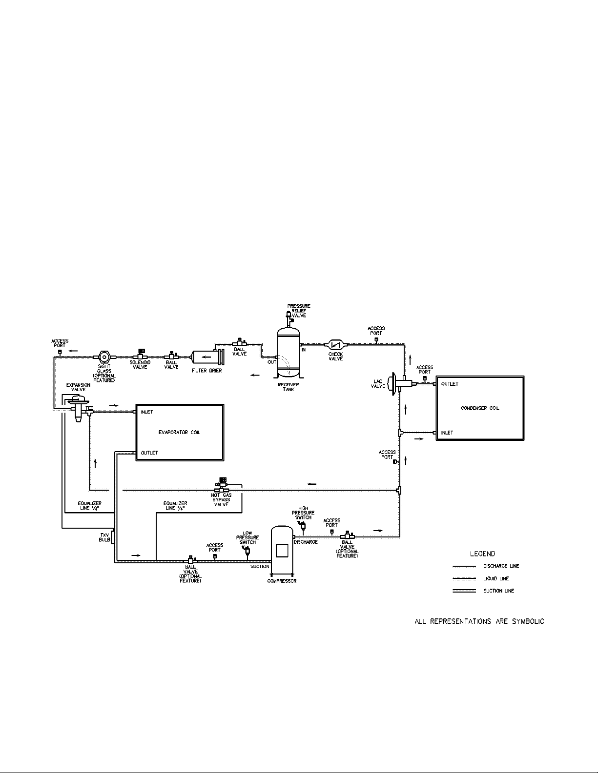
LAC Valve:
The LAC valve is a non-adjustable three way
valve that modulates to maintain receiver
pressure. As the receiver pressure drops below
the valve setting (180 psig for R-22 and 295 psig
for R-410A), the valve modulates to bypass
discharge gas around the condenser. The
discharge gas warms the liquid in the receiver
and raises the pressure to the valve setting. The
following schematic shows an example system
using the LAC valve.
Piping Schematic of Example system using the LAC valve.
6
Page 7
INSTALLATION cont.
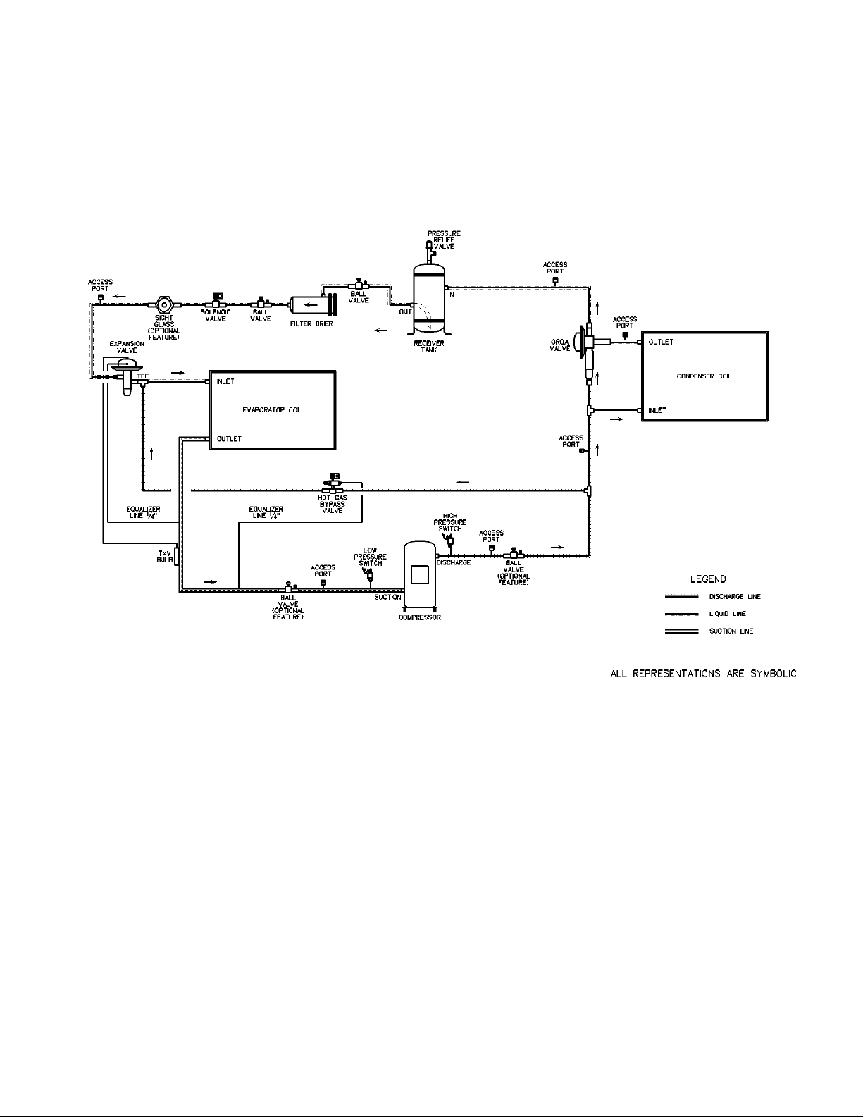
OROA Valve:
This system uses a nonadjustable head pressure
control valve that performs the function of
limiting the flow of liquid refrigerant from the
condenser and at the same time regulates the
flow of the hot gas around the condenser to the
receiver. The valve setpoint is 180 psig. This
valve is called an OROA valve (Open on Rise of
Outlet pressure). The following schematic
shows an example system using the OROA
valve.
Piping Schematic of Example system using the OROA valve.
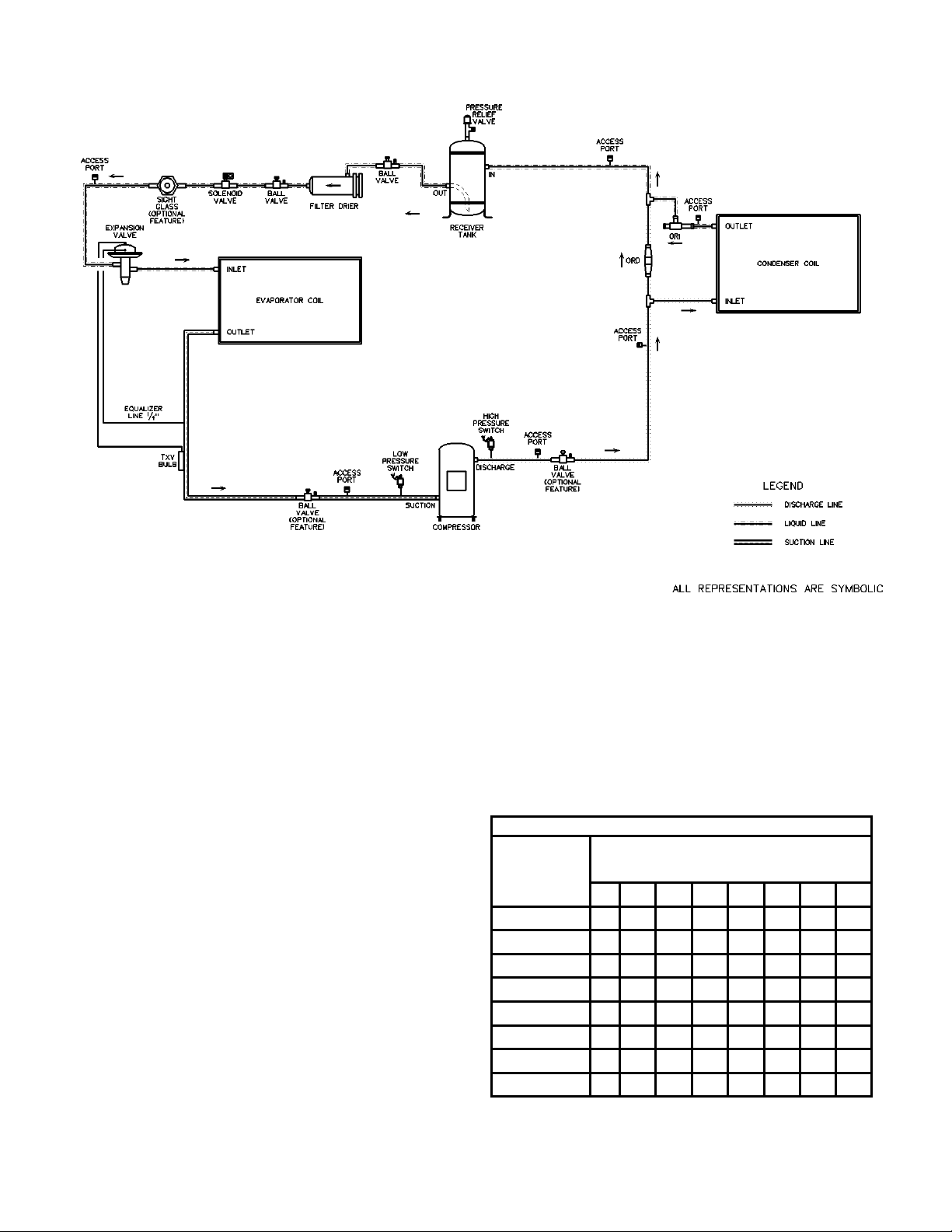
ORI/ORD Valves:
This system uses a two-valve arrangement. The
head pressure control valve is an inlet pressure
regulating valve and responds to changes in
condensing pressure. This valve is located in the
discharge of the condenser and is called an ORI
valve (Open on Rise of Inlet pressure). As the
ambient temperature drops, the condenser
capacity increases and the condensing pressure
falls, causing the ORI to modulate toward the
closed position. The condenser bypass valve is a
pressure differential valve that responds to
changes in the pressure differential across the
valve. This valve is called an ORD valve (Open
on Rise of Differential pressure). As the ORI
starts to restrict liquid flow from the condenser, a
pressure differential is created across the ORD.
When the differential reaches the setpoint, the
ORD starts to open and bypass hot gas to the
liquid line. The ORI valve is adjustable from 65
to 225 psig (factory setting of 180 psig). The
ORD is not adjustable. On refrigeration systems
that are too large for a single ORI and ORD
valve, there will be two ORI and two ORD
valves in parallel. The schematic on the
following page shows an example system using
the ORI/ORD valves.
7
Page 8
INSTALLATION cont.
Piping Schematic of Example system using the ORI/ORD valve.
The pressure setting of the ORI valve determines
how well the system will operate. The proper
setting is a function of the specific system in
which is installed. Generally, the setting should
be equivalent to a condensing temperature of
90°F to 100°F or a receiver pressure equivalent
to a temperature of 80°F to 90°F. This means
that as the ambient temperature falls below 70°F,
the head pressure control valve will begin to
throttle. To adjust the ORI valve, remove the cap
and turn the adjustment screw with the proper
size hex wrench (1/4” for ORI-6 and 5/16” for
ORI-10). A clockwise rotation increases the
valve setting while a counter-clockwise rotation
decreases the setting. To obtain the desired
setting, a pressure gauge should be used at the
compressor discharge service valve so the effects
of any adjustment can be observed. Small
adjustments are recommended in order to allow
the system adequate time to stabilize after each
adjustment.
Condenser Flooding:
In order to maintain head pressure in the
refrigeration system, liquid refrigerant is backed
up in the condenser to reduce condenser surface.
The following chart shows the percentage that a
condenser must be flooded in order to function
properly at the given ambient temperature.
PERCENTAGE OF CONDENSER TO BE FLOODED
Ambient
Temperature
(
°F)
70°
60°
50°
40°
30°
20°
0°
-20°
Evaporating Temperature (
0° 10° 20° 30° 35° 40° 45° 50°
40 24 0 0 0 0 0 0
60 47 33 17 26 20 10 4
70 60 50 38 45 40 33 28
76 68 60 50 56 52 46 42
80 73 66 59 64 60 55 51
86 77 72 65 69 66 62 59
87 83 78 73 76 73 70 68
91 87 82 77 80 79 76 73
°F)
8
Page 9
INSTALLATION cont.
During higher ambient temperatures the entire
condenser is required to condense refrigerant.
During these higher ambient temperatures, a
receiver tank is used to contain the refrigerant
that was required to flood the condenser during
low ambient operation. The receiver must be
sized to contain all of the flooded volume
otherwise there will be high head pressures
during higher ambient conditions.
Electrical:
• The single point electrical power connections
are made in the electrical control compartment.
• Check the unit data plate voltage to make sure
it agrees with the power supply. Connect power
to the unit according to the wiring diagram
provided with the unit.
• The power and control wiring may be brought
up through the utility entry. Protect the branch
circuit in accordance with code requirements.
Control wires and power should not be run inside
the same conduit. The unit must be electrically
grounded in accordance with the current National
Electric Code.
• Power wiring is to the unit terminal block or
main disconnect. All wiring beyond this point
has been done by the manufacturer and cannot be
modified without effecting the unit's
agency/safety certification.
Note: Startup technician must check motor
amperage to ensure that the amperage listed
on the motor nameplate is not exceeded.
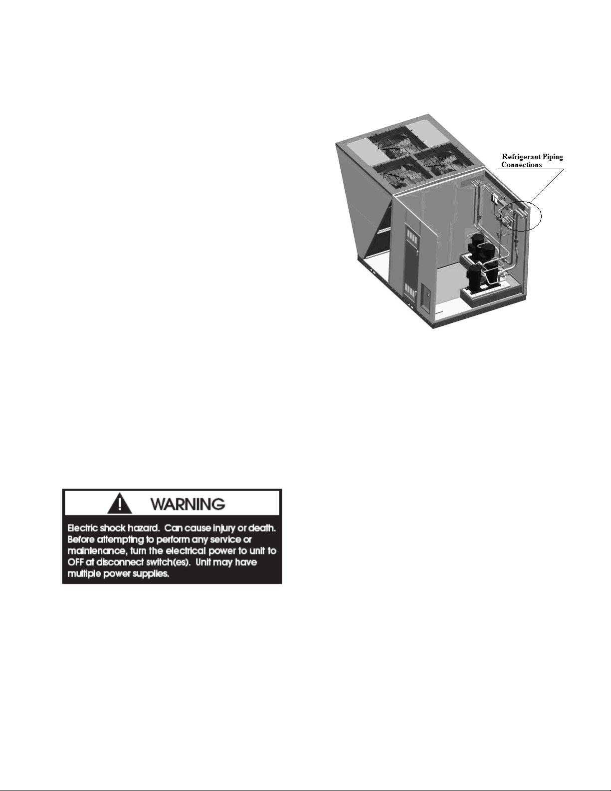
Refrigerant Piping Connections
• CL condensing unit refrigerant piping
connections are located in the upper corner of the
service vestibule side of the unit (opposite the
condenser section) as shown in the figure.
• The piping connections are protected with a
shipping cover that must be removed prior to
copper connection and installation.
Evaporative-cooled Condenser Field Piping
Connections:
• There are two field water connections that must
be made for the evaporative-cooled condenser.
There is a ¾” PVC socket city make-up water
connection and a 2” PVC socket drain
connection (as shown on the next page). This
drain should connect to a sanitary sewer or other
code permitted drain. These connections can go
through the base or the wall of the unit.
• There is a cutout in the base with a cap that is
1” tall and the cap is sealed to the unit base to
prevent any leaks in the unit from penetrating
into the building. Any piping through the base
should go through a field cutout in this cap. The
pipes must be sealed to the cap once the piping is
complete to prevent any leaks in the unit from
penetrating into the building.
• A field cutout must be made in the wall if the
evaporative-cooled condenser piping is to go
through the unit wall. This cutout must be
sealed once the piping is installed to prevent
water from leaking into the unit.
9
Page 10
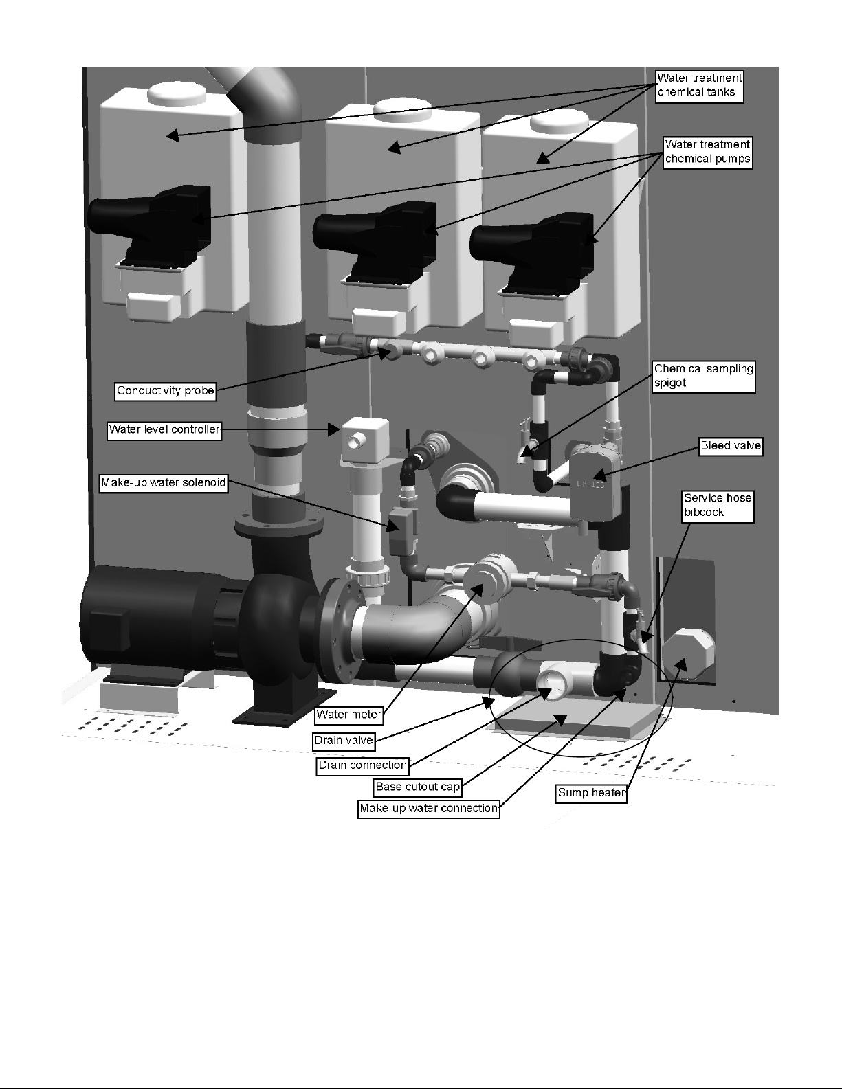
Diagram of Evaporative-cooled condenser Section including field water connections and base cutout
tap
10
Page 11
STARTUP
Pre-Startup:
After the installation and immediately before the
startup of the condenser be sure that these items
have been checked.
1. Verify that electrical power is available to the
unit.
2. Verify that any remote stop/start device is
requesting the condenser to start.
While performing the Startup, use the
Condensing Startup Form at the back of this
booklet to record motor amps and any other
comments.
Startup:
• Use the General Check List at the top of the
Startup Form to make a last check that all the
components are in place and the power supply is
energized.
Note: Condensing fan operation should start
with the first compressor.
• Cycle through all the compressors to confirm
that all are operating within tolerance.
• When unit is running, observe the system for a
complete operation cycle to verify that all
systems are functioning properly.
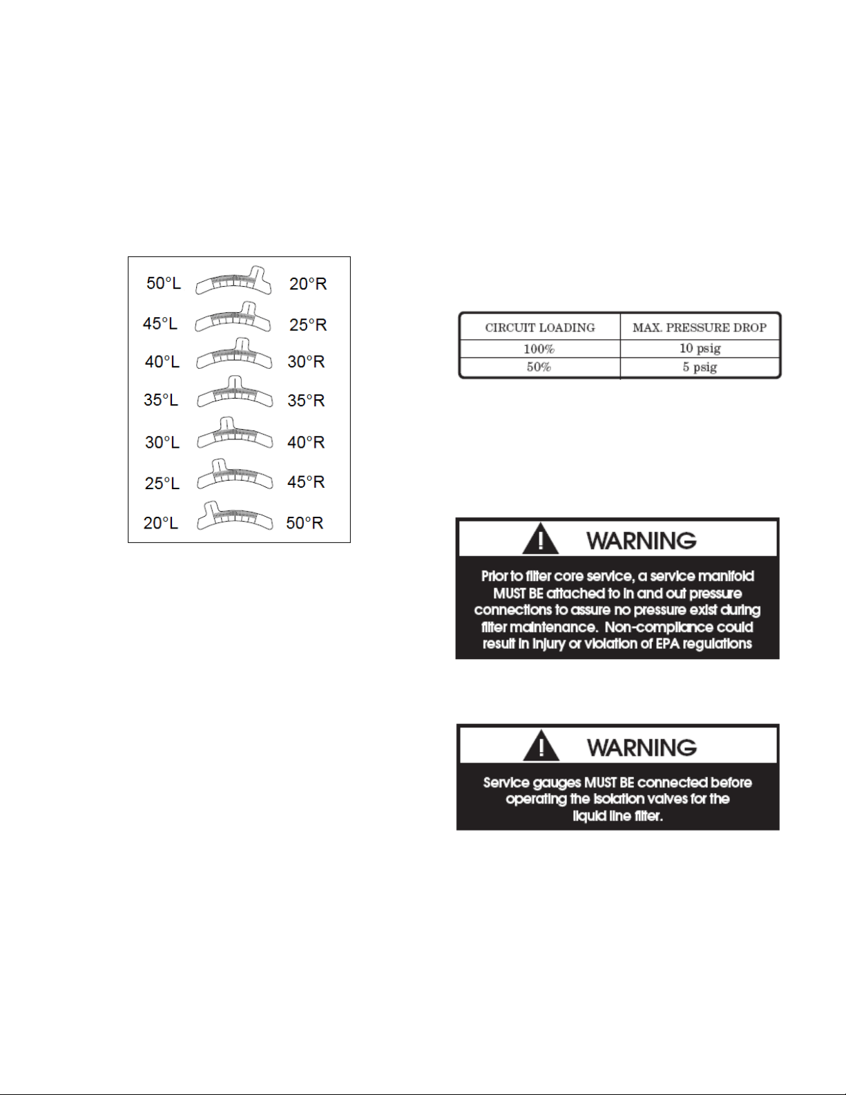
Axial Flow Fans:
Multi-Wing Z Series Aluminum Fan Blade
Pitch Angle Setting Instructions:
Before You Begin, to maintain balance of fan:
• Mark the hub castings across a joint, so the fan
hub can be reassembled in the same orientation.
• Mark the location of any balancing weight.
Balancing weight will be on the outer bolt circle,
in the form of washers, and/or longer bolts, or an
additional balancing nut.
• Number the blades and blade sockets, so that
they are replaced into their original position.
• If possible, note the location of the pitch setting
pin in the blade socket, and whether pin is
located in the Hub or Retainer half of the fan.
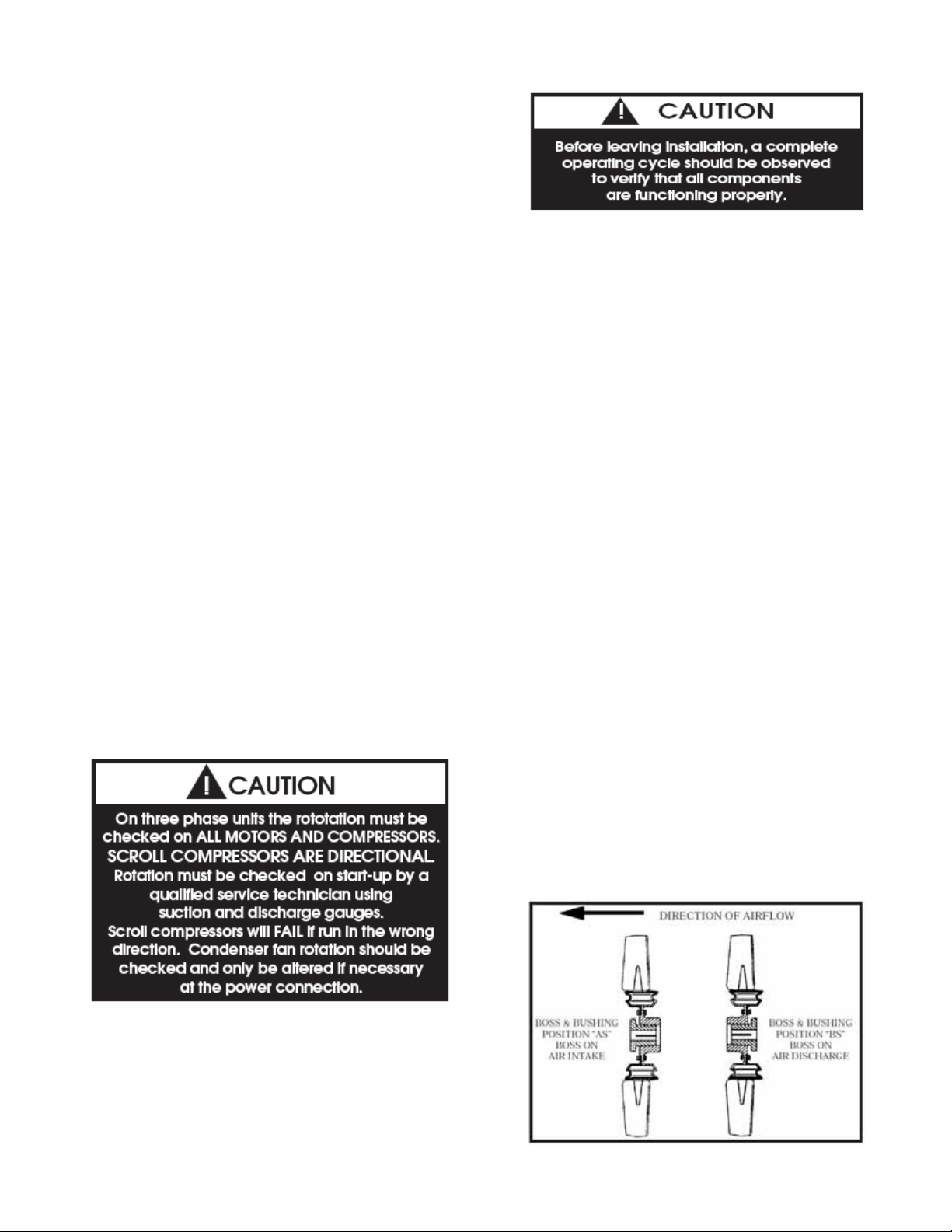
Step 1. Determine Boss Location Code: “A” or
“B” The boss is the center section of the hub
through which the fan is mounted to the shaft,
and typically contains either setscrews or a
center-tapered hole where the bushing inserts.
Select boss location A or B:
A is the boss on air inlet, including AS
configurations.
B is the boss on air discharge, including BS.
For flange mounted fans, use boss location A for
R rotation fans, and boss location B for L
rotation fans.
• While performing the check, use the Condenser
Startup Form to record observations of amps and
refrigerant pressures.
• When all is running properly, place the
controller in the Run mode and observe the
system until it reaches a steady state of operation.
11
Page 12
STARTUP cont.
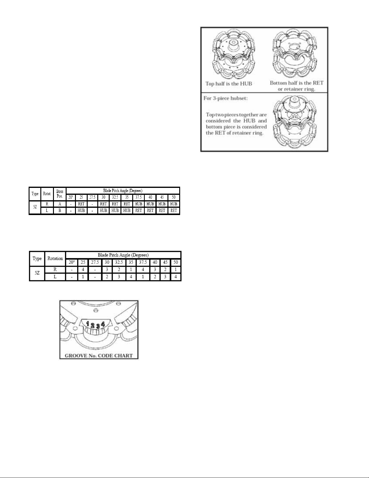
Step 2. Find Blade Pitch Angle:
( 20, 25, 27.5, 30, 32.5, 35, 37.5, 40, 45 or 50 )
• Carefully disassemble fan on flat surface and
note in which groove the pin is located. Refer to
groove number code diagram.
• Using diagrams in step 5, determine if the pin
was in the hub (HUB) or retainer side (RET) of
fan.
• Using table in step 4, find the possible blade
pitch.
• Using table in step 3, select your blade angle
based on whether your pin was in the HUB or
RET.
Step 3. Determine Hub/Retainer Code: “HUB”
or “RET”
Step 4. - Determine Groove Number: 1 or 2 or 3
or 4
Step 5. Final Assembly
Definition of HUB and RET for purposes of
instructions. For 2-piece hubset:
Using the HUB or RET code found in Step 3:
• If code is HUB, place the hub down on work
surface first (one or two pieces, depending on
above).
• If code is RET, place one retainer ring only
down on the work surface first. (A weighted
coffee can could be used to elevate the fan from
the work surface).
• Using the groove number, place the locking pin
in the groove number that was found in Step 4.
Insert Blades:
• Place the blade over the pin in the hub/retainer
blade socket, so that the pin also fits into the
appropriate pitch angle groove in the blade.
• Repeat for all blades.
• Assemble hub set together, aligning the match
marks that were made.
• Replace any balancing weight to its original
position.
• To finish, tighten the bolts in a cross pattern to
5 to 6 ft-lbs of torque.
Multi-Wing W Series Black Glass Reinforced
Polypropylene Fan Blade Pitch Angle Setting
Instructions:
Step 1. Note original position of retaining plates,
center boss and all hardware including additional
hardware used for balancing.
Step 2. Remove all the bolts and nuts.
12
Page 13
STARTUP cont.
Step 3. Determine blade rotation – on the
concave side of the blade is a blade marking
showing 6WR, 6WL, 7WL, 7WR, or 9WR. The
“L” and “R” denote the rotation of the blade.
Step 4. Replace the pitch insert in the blade root
with an insert of the desired pitch.
Compressors:
The scroll compressors are fully hermetic and
require no maintenance except keeping the shell
clean.
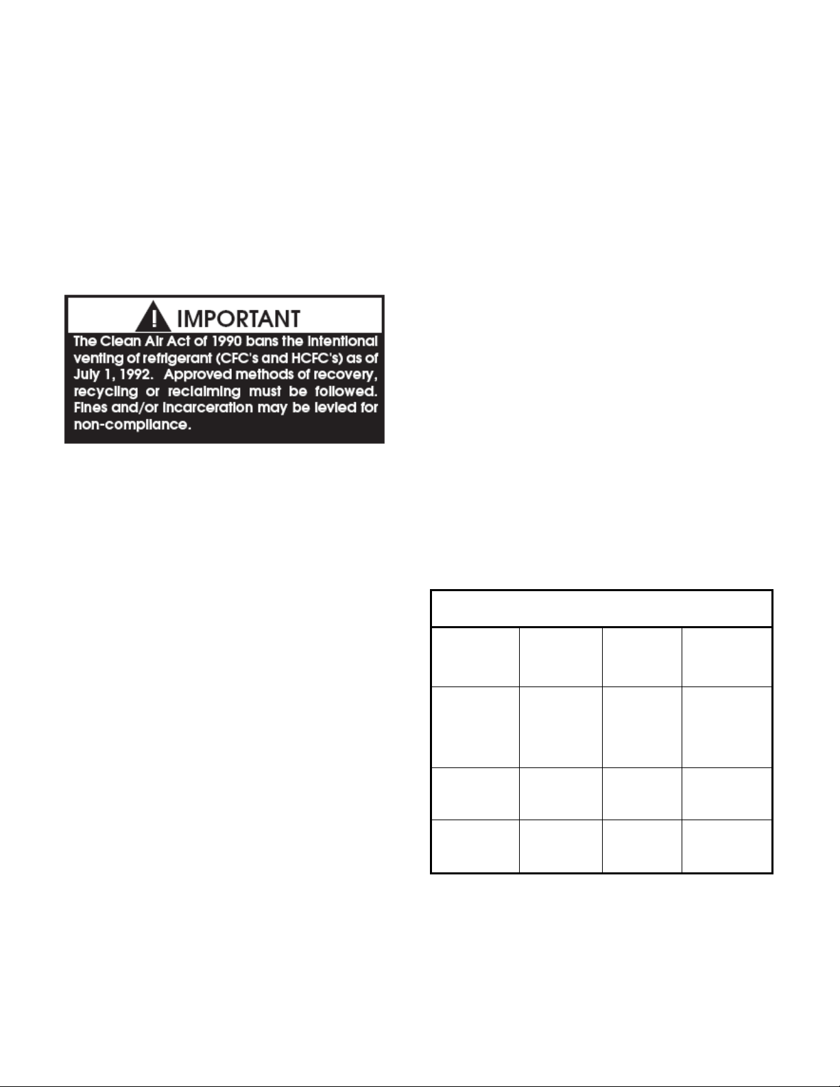
Refrigerant Filter Driers:
Each refrigerant circuit contains a replaceable
core filter drier. Replacement is recommended
when there is excessive pressure drop across the
assembly or moisture is indicated in a liquid line
sight glass.
The filter driers are provided with pressure taps
and shutoff valves for isolation when changing
the core. For safety purposes a service manifold
must be attached prior to filter maintenance.
Step 5. Replace blades to their original location.
Step 6. Replace all nuts, bolts, and washers on
the fan hub.
Step 7. Replace retaining plates and center boss
to original location.
Step 8. Tighten nuts and bolts to 14 ft-lbs of
torque.
SERVICING AND MAINTENANCE
General:
• Qualified technicians must perform routine
service checks and maintenance. This includes
reading and recording the condensing and
suction pressures and checking for normal subcooling and superheat (see charging information
beginning on page 14).
• Air-cooled and evaporative-cooled condenser
units require different maintenance
schedules/procedures. Unit specific instructions
for both types are included in this manual.
Evaporator/Heat Exchangers:
Normally no maintenance or service work will be
required for a matching direct expansion
evaporator with a thermal expansion valve to
regulate refrigerant.
13
Page 14
SERVICING AND MAINTENANCE
cont.
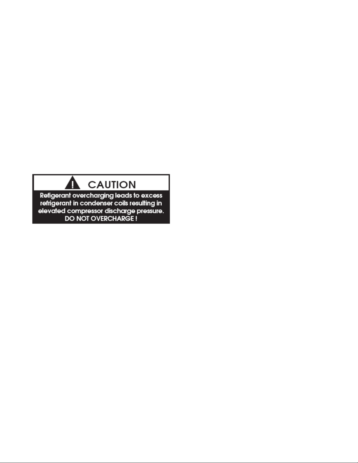
Charging Refrigerant:
• Charging a system in the field must be based on
determination of liquid sub-cooling and
evaporator superheat. On a system with a
thermostatic expansion valve liquid sub-cooling
is more representative of the charge than
evaporator superheat but both measurements
must be taken.
Before Charging:
• Refer to the Unit Nameplate to determine the
proper refrigerant to charge the system with.
• The unit being charged must be at or near full
load conditions before adjusting the charge.
• Units equipped with hot gas bypass must have
the hot gas bypass valve closed to get the proper
charge.
• Units equipped with hot gas reheat must be
charged with the hot gas valve closed while the
unit is in cooling mode.
• After adding or removing charge the system
must be allowed to stabilize, typically 10-15
minutes, before making any other adjustments.
• The type of unit and options determine the
ranges for liquid sub-cooling and evaporator
superheat. Refer to Table 1 when determining
the proper sub-cooling.
• The vertical rise of the liquid line must be
known in order to adjust the sub-cooling range
for proper charge.
• Units equipped with low ambient (0°F) option
see special charging instructions at the end of the
charging instructions.
Checking Liquid Sub-cooling:
1. Measure the temperature of the liquid line as
it leaves the condenser coil.
2. Read the gauge pressure reading of the liquid
line close to the point where the temperature was
taken. You must use liquid line pressure as it
will vary from discharge pressure due to
condenser coil pressure drop.
3. Convert the pressure obtained in Step 2 to a
saturated temperature using the appropriate
refrigerant temperature-pressure chart.
4. Subtract the measured liquid line temperature
in Step 1 from the saturated temperature in Step
3 to determine the liquid sub-cooling.
5. Compare calculated sub-cooling to TABLE 1.
for the appropriate unit type and options.
Checking Evaporator Superheat:
1. Measure the temperature of the suction line
close to the compressor.
2. Read gauge pressure at the suction line close
to the compressor.
3. Convert the pressure obtained in Step 2 to a
saturated temperature using the appropriate
refrigerant temperature-pressure chart.
4. Subtract the saturated temperature in Step 3
from the measured suction line temperature in
Step 1 to determine the evaporator superheat.
5. Compare calculated superheat to TABLE 1 for
the appropriate unit type and options.
TABLE 1
Sub-cooling
W/Hot Gas
Reheat (°F)
Air Cooled
Condenser
Evaporative
Cooled
Condenser
Water
Cooled
Condenser
Sub-
cooling
(°F)
12-18* 8-15** 15-22*
6-10* 8-15** 8-12*
6-10* 8-15** 8-12*
Superheat
(°F)
* Sub-cooling must be increased by 3°F per 20
feet of vertical liquid line rise for R-22 and 2°F
for R-410A
** Superheat will increase with long suction line
runs.
14
Page 15
SERVICING AND MAINTENANCE
cont.
Adjusting Sub-cooling and Superheat
Temperatures:
The system is overcharged if:
1. the sub-cooling temperature is too high and
2. the evaporator is fully loaded (low loads on
the evaporator result in increased sub-cooling)
and
3. the evaporator superheat is within the
temperature range as shown in TABLE 1 (high
superheat results in increased sub-cooling)
Correct an overcharged system by reducing the
amount of refrigerant in the system to lower the
sub-cooling.
The system is undercharged if:
1. the superheat is too high and
2. the sub-cooling is too low
• Correct an undercharged system by adding
refrigerant to the system to reduce superheat and
raise sub-cooling.
• If the sub-cooling is correct and the superheat is
too high, the TXV may need adjustment to
correct the superheat.
Special Charging Instructions:
• For units equipped with low ambient refrigerant
flood back option being charged in the summer
when the ambient temperature is warm:
Once enough charge has been added to get the
evaporator superheat and sub-cooling values to
the correct setting more charge must be added.
Add approximately 80% of the receiver tank
volume to the charge to help fill the receiver
tank. The additional charge is required for the
system when running in cold ambient conditions.
• For units equipped with low ambient refrigerant
flood back option being charged in the winter
when the ambient temperature is cold:
1. Once enough charge has been added to get the
evaporator superheat and sub-cooling values to
the correct setting more charge may need to be
added. If the ambient temperature is 0°F no
more charge is required. If the ambient
temperature is around 40°F add approximately
40% of the receiver tank volume.
2. The unit will have to be checked for proper
operation once the ambient temperature is above
80°F.
Lubrication:
• All original motors and bearings are furnished
with an original factory charge of lubrication.
Certain applications require bearings be relubricated periodically. The schedule will vary
depending on operating duty, temperature
changes, or severe atmospheric conditions.
• Bearings should be re-lubricated at normal
operating temperatures, but not when running.
Rotate the fan shaft by hand and add only enough
grease to purge the seals. DO NOT
OVERLUBRICATE.
Service Information:
If the unit will not operate correctly and a service
company is required, only a company with
service technicians qualified and experienced in
both condensing units and air conditioning are
permitted to service the systems to keep
warranties in effect. If assistance is required, the
service technician must contact AAON.
Note: Service technician must provide the
model and serial number of the unit in all
correspondence with AAON.
Replacement parts for AAON equipment may be
obtained from AAON. When ordering parts,
always reference the unit model number, serial
number and part number.
15
Page 16
AAON, Inc.
www.aaon.com
Customer Service Department
2425 South Yukon Ave • Tulsa, OK 74107
Phone: 918-583-2266 • Fax: 918-382-6364
ALWAYS USE AAON SPECIFIED PARTS
To order parts from the AAON Parts store
online go to www.aaonparts.com.
EVAPORATIVE-COOLED
CONDENSER
• Evaporative cooling equipment rejects heat by
evaporating a portion of the recirculated water
spray and discharging it from the unit with the
hot, saturated air. As the spray water evaporates,
it leaves behind the mineral content and
impurities of the supply water. If these residuals
are not purged from the water distribution
system, they will become concentrated and lead
to scaling, corrosion, sludge build-up and
biological fouling.
• A water treatment monitoring and control
system has been furnished with this unit. Be sure
to read the complete manual that has been
furnished. All water treatment is a combination
of bleed water and chemical treatment for proper
control of the residuals and to prevent any
biological contamination.
may form solutions and deposits harmful to the
products and personnel.
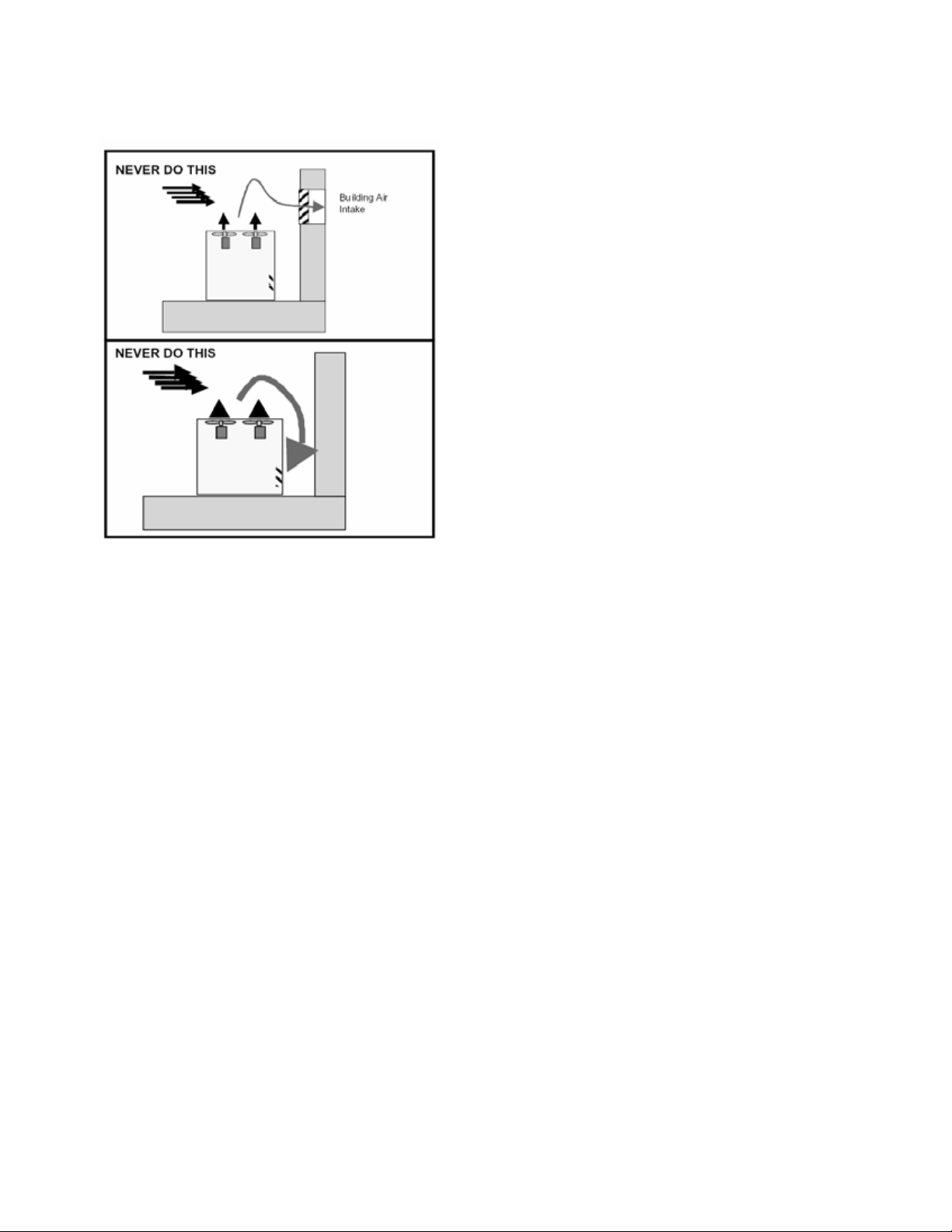
Safety:
The recirculating water system contains chemical
additives for water quality control and biological
contaminants removed from the air by the
washing action of the water. Personnel exposed
to the saturated effluent, drift, or direct contact
should use proper precaution. Proper location of
the evaporative-cooled condenser requires good
judgment to prevent the air discharge from
entering fresh air intakes or to avoid allowing
contaminated building exhaust from entering the
condenser.
Follow local and national codes in locating the
evaporative-cooled condenser but as minimum
the evaporative-cooled condenser sump must be
15 feet from the nearest intake.
GENERAL INFORMATION
Severe Service:
The following recommended maintenance
procedures are basic requirements for normal
operating environments. For severe operating
conditions, the frequency of inspection and
service should be increased. Air containing
industrial and chemical fumes, salt, dust, or other
airborne contaminates and particulates will be
absorbed by the recirculating water system and
16
Page 17
EVAPORATIVE-COOLED
CONDENSER cont.
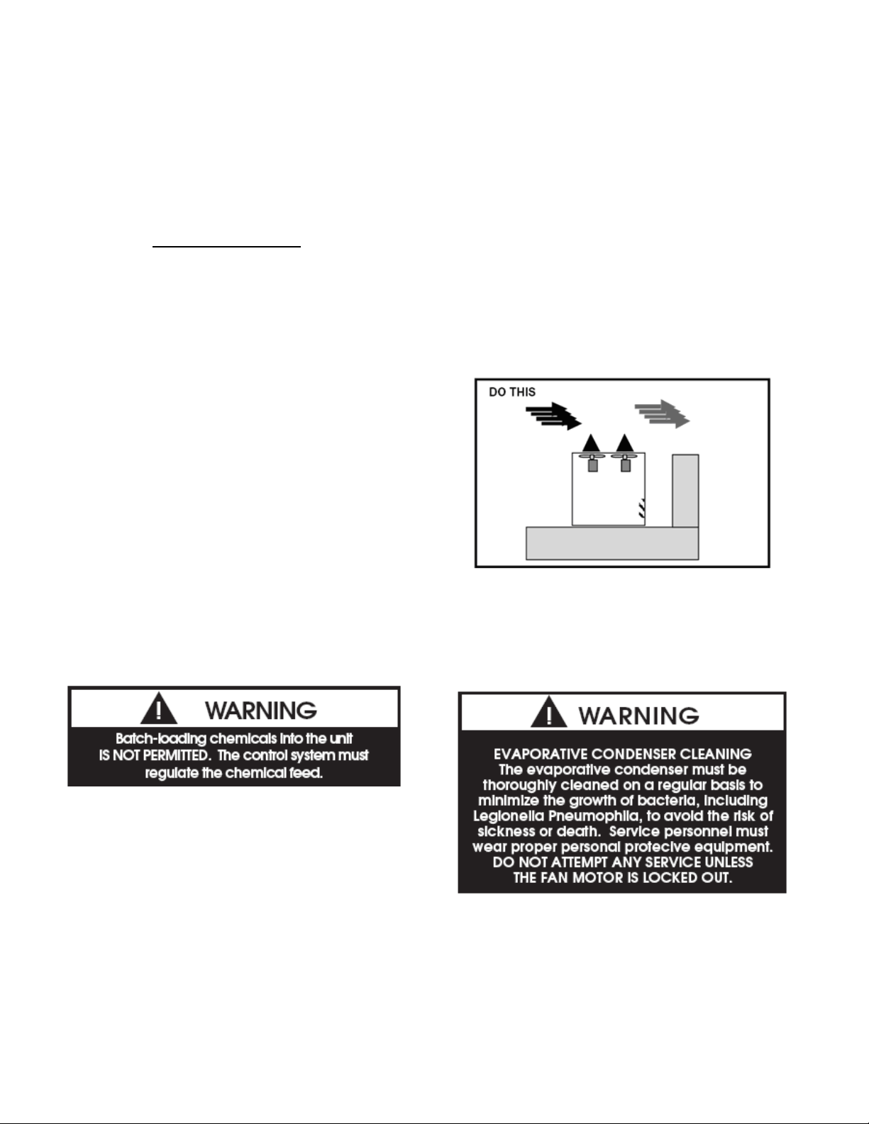
Performance:
Improper location of the evaporative-cooled
condenser may seriously degrade the capacity of
the equipment. Make sure the equipment is
located such that discharge air from the
condenser does not enter the condenser air inlet.
Warranties:
Please refer to the limitation of warranties in
effect at the time of purchase.
Condenser Tube Inspection:
The coil is leak tested at 450 P.S.I.G. before
shipment. AAON will not be responsible for loss
of refrigerant. It is the responsibility of the
installer to verify that the system is sealed before
charging with refrigerant. If the unit is operated
during low ambient temperature conditions,
freeze protection for the recirculating water
system must be provided.
Freeze Protection:
In order to prevent water temperatures from
dropping below 50°F, this unit is equipped with a
variable frequency drive (VFD) on the fan
motors when the refrigeration system is
operating.
Recirculating Water System:
Electric sump heaters are available to keep the
sump water from freezing when the refrigeration
system is not operating. An electric resistance
heater is supplied in the vestibule when sump
heaters are selected.
Note: The condenser should not be operated
with the fan on and the pump cycled on and
off to maintain head pressure control under
any conditions. The unit is equipped with a
water temperature controller which varies fan
speed to maintain sump water temperature.
This unit is not equipped with a compressor
discharge pressure controller for fan speed
modulation and therefore can not be operated
without water flow.
PRE START-UP
Do not start the evaporative-cooled condenser or
compressors without installation of proper water
treatment chemicals. Contact your local water
treatment expert for correct selection of water
treatment chemical, adjustment of chemical feed
and bleed rates.
Cleanliness:
Dirt and debris may accumulate in the sump
during shipping and storage. The sump should be
cleaned prior to start-up to prevent clogging the
water distribution system. Any surfaces that
show contamination should be cleaned ONLY
with a commercial stainless steel cleaner to
restore the initial appearance. The inlet screens
should be inspected for foreign material.
Pump Operation:
Before initial start of the pump, check as follows:
1. Be sure that pump operates in the direction
indicated by the arrow on the pump casing.
Check rotation each time motor leads have been
disconnected.
2. Check all connections of motor and starting
device with wiring diagram. Check voltage,
phase and frequency of line circuit with motor
name plate.
3. Check suction and discharge piping and
pressure gauges for proper operation.
17
Page 18

EVAPORATIVE-COOLED
CONDENSER cont.
4. Turn rotating element by hand to assure that it
rotates freely.
Running:
Periodically inspect pump while running, but
especially after initial start-up and after repairs.
1. Check pump and piping for leaks. Repair
immediately.
2. Record pressure gauge readings for future
reference.
3. Record voltage, amperage per phase, and kW.
Condenser Fan Motors:
• The direct-drive condenser motors on AAON
evaporative-cooled condensers are 1200-rpm
premium efficiency motors controlled by a VFD.
These motors are totally enclosed air over motors
with weep holes in the bottom end bell so that
any condensation can drain out of the motor.
• The motors have a small electric resistance
heater installed inside the casing to keep the
motors warm when they are deactivated. The
heaters are designed to keep the interior of the
motor 10°F warmer than the surrounding
ambient temperature. This prevents condensation
from forming inside the motor.
• Ensure that fan is tightly mounted to the motor
shaft and the motor mounting bolts are aligned
and secure.
Water Make-up Valve:
• The sump water level is controlled by a set of
conductivity probes at different levels in the
sump. This water level controller is located in
the vestibule behind the condenser pump. There
are four conductivity probes in this controller.
There is a reference probe (shown as “ref” on the
wiring diagram). This probe is one of the two
longest probes. The other long probe is the low
water level probe (shown as “lo” on the wiring
diagram). The medium length probe is for the
medium water level (shown as “med” on the
wiring diagram). The short probe is for the high
water level (shown as “hi” on the wiring
diagram). There is a solenoid valve in the makeup water line that is activated by the water level
controller. The water level controller determines
the level of water in the sump based on
conductivity between two probes. If the
controller sees conductivity between two probes,
it knows that water is at least at the level of that
probe.
• If the water in the sump is below the low probe,
it will not allow the condenser pump or the sump
heater to operate. It will activate the make-up
water solenoid to try to fill the sump assuming
water is flowing to the unit. Once water is above
the low probe, it will allow the condenser pump
and sump heater (if ordered and the ambient
temperature is below 40°F) to operate. The
make-up water solenoid will remain activated
until water gets to the high water level. The
make-up water solenoid will deactivate until
water gets to the medium water level. In normal
operation, the water level should swing between
the medium and high water levels. The
maximum high water level should be 1” below
the overflow drain which occurs after the makeup water valve shuts off when the water level
reaches the high level probe.
• Make-up water supply pressure should be
maintained between 15 and 60 psig for proper
operation of the valve. The make-up water valve
assembly should be inspected monthly and
adjusted as required. Replace the valve seat if
leakage occurs when the valve is in the closed
position.
18
Page 19

EVAPORATIVE-COOLED
CONDENSER cont.
Water Treatment System:
• All AAON evaporative-cooled condensers
come equipped with a water treatment system
that should be maintained by a local water
treatment professional trained in the water
treatment of evaporative condensers. This
system consists of a controller, three chemical
pumps and storage tanks, a conductivity sensor, a
motorized ball valve for water bleed, and a water
meter.
• One chemical pump and tank is typically used
for a descaling chemical to prevent scale from
forming in the condenser. The other two pumps
and tanks are typically used for two different
biocides (to kill any microorganisms that could
grow in the condenser). Two biocides are used
to prevent organisms from becoming resistant to
one chemical.
• The mineral content of the water must be
controlled. All make-up water has minerals in it.
As water is evaporated from the condenser, these
minerals remain. As the mineral content of the
water increases, the conductivity of the water
increases. The water treatment controller
monitors this conductivity. As the water
conductivity rises above set point, the controller
will open a motorized ball valve on the discharge
side of the condenser pump and dumps water
into the condenser drain until conductivity is
lowered. While the motorized ball valve is
opened, the controller will not disperse
chemicals.
• The chemicals are dispersed by the water
treatment controller based on the scheduled input
by the water treatment professional. (See the
separate manual for the water treatment controls
for specific programming information.)
• The water meter measures the quantity of
make-up water used by the condenser.
• Any water treatment program must be
compatible with stainless steel, copper,
aluminum, ABS plastic and PVC. Batch feed
processes should never be used as concentrated
chemicals can cause corrosion. Never use
hydrochloric acid (muratic acid) as it will
corrode stainless steel.
Sequence of Operation:
• On a call for cooling, the condenser pump is
activated. A pressure switch in the pump
discharge is bypassed for six seconds by a time
delay relay in order for the pump to establish
recirculating water flow. If flow is not proven
within the six seconds, the pressure switch opens,
breaking the safety circuit, thereby shutting down
the entire system. This pressure switch is set to
close at 3 psi and open at 1 psi.
• A Johnson Controls S350C measures the water
temperature in the pump discharge line. If the
sump water temperature exceeds 105°F, the
cooling system will be shut down thereby
preventing damage to the evaporative condenser.
• If a fault occurs in the evaporative condenser
fan motor VFD, normally closed fault terminals
on the VFD will interrupt the safety circuit,
thereby shutting down the system.
• If the VFD does fault and cannot be reset, there
is a VFD bypass switch mounted near the VFD.
This switch has four positions—line, off, drive,
and test. The “line” position will bypass the
VFD, sending power to the motor. In this
position, the condenser fans will run at full
speed. The “off” position will not allow power
to pass through the switch. This functions as a
disconnect switch. The “drive” position runs
power through the VFD. This is the normal
operation for the switch. The “test” position
routes power to the VFD but not to the motor.
This is useful for running tests on the VFD
without sending power to the motor.
• A Johnson Controls A350P controls the VFD
speed. This device sends a 0-10 VDC signal to
the VFD. This controller is set to maintain a
sump temperature of 70°F. On a rise in sump
temperature, the controller increases the voltage
to the VFD, increasing the speed of the
condenser fans. Conversely, on a drop in sump
temperature, the controller will decrease the
voltage to the VFD, decreasing the speed of the
condenser fans.
• An outside air thermostat does not allow the
condenser to operate when the ambient
temperature is below 35°F.
19
Page 20

EVAPORATIVE-COOLED
CONDENSER cont.
MAINTENANCE RECOMMENDATIONS
Pump Maintenance:
• Cleaning - Remove oil, dust, water, and
chemicals from exterior of motor and pump.
Keep motor air inlet and outlet open. Blow out
interior of open motors with clean compressed
air at low pressure.
• Labeled Motors - It is imperative for repair of a
motor with Underwriters’ Laboratories label that
original clearances be held; that all plugs, screws,
other hardware be fastened securely, and that
parts replacements be exact duplicates or
approved equals. Violation of any of the above
invalidates Underwriters’ Label.
Fan Motor Maintenance:
Same as pump maintenance
Access Doors:
If scale deposits or water is found around the
access doors, adjust door for tightness. Adjust as
necessary until leaking stops when door is
closed.
Bearings - Lubrication:
Every 6 months or after a prolonged shut down.
Use waterproof, lithium based grease. Below
32°F - Esso Exxon or Beacon 325. Above 32°F –
Mobil Mobilox EP2, Shell Alvania EP2 or
Texaco RB2.
Recommended Monthly Inspection:
1. Clean sump section interior. Dirt and other
impurities which have accumulated in the sump
should be removed from the sump area. Shut off
make-up water ball valve and open the drain
connection for flushing of the sump.
2. Clean dirt out of sump using a water hose (not
a pressure washer).
3. Clean sump suction strainer.
4. Check water operating level. Adjust float as
required.
5. Inspect fan motor(s) and water circulation
pump(s) and lubricate per the lubrication
nameplate or manufacture’s recommendations.
6. Inspect axial fans and eliminators removing
any debris which may have accumulated during
operation.
7. Inspect the water distribution system to insure
that nozzles and spray orifices are functioning
correctly. The inspection should be made with
the circulation pump on and fans off.
Mist Eliminators:
The mist eliminators must be correctly
positioned when they are replaced during
cleaning or service.
Air Inlet:
Inspect the air inlet louvers and mist eliminators
into the condenser section on a monthly basis to
remove any paper, leaves or other debris that
may block the airflow.
Stainless Steel Base Pan:
The base pan under the tube bundles is stainless
steel and may sometimes become tarnished due
to contamination. These surfaces should be
inspected yearly to ensure they remain clean of
any contamination that may result in damage.
Any surfaces that show contamination should be
cleaned ONLY with a commercial stainless steel
cleaner to restore the initial appearance.
Propeller Fans and Motors:
The fans are directly mounted on the motor
shafts and the assemblies require minimal
maintenance except to assurance they are clear of
dirt or debris that would impede the airflow.
Recommended Annual Inspection:
In addition to the above maintenance activities, a
general inspection of the unit surface should be
completed at least once a year. Remove spray
header and flush out.
Cleaning:
Mechanical cleaning, including pressure
washing, should never be performed as surfaces
and seals could be damaged. Chemical cleaning
that is safe for stainless steel, copper, aluminum,
ABS plastic and PVC is the only acceptable
means of cleaning the evaporative condenser. A
proper water treatment program should reduce
cleaning needs.
20
Page 21

EVAPORATIVE-COOLED
CONDENSER cont.
WATER QUALITY
Recirculating Water Quality Guidelines:
• Cycles of concentration (the ratio of dissolved
solids in recirculated water to dissolved solids in
make-up), should be determined and monitored
frequently by a competent water treatment
expert.
• To limit cycles of concentration to maintain the
above guideline, it is necessary to “bleed” a
certain portion of the recirculated water. This is
achieved automatically with a solenoid valve
actuated by a conductivity meter set at the
desired conductivity corresponding to the desired
cycles of concentration. It should be noted that
these are guidelines and even though these
individual values are met, under certain
conditions the water quality can be aggressive.
For example, water with very low alkalinity and
levels of chlorides and sulfates approaching
maximum recommended levels can be corrosive.
Mechanical Cleaning:
Do not attempt to mechanically clean the copper
tubing in the evaporative-cooled condenser. Do
not use wire brushes or any other mechanical
device on the copper tubing. Severe damage may
result. Contact your water treatment expert for
recommendations on chemical cleaning
procedures.
Parts:
Contact your local AAON Representative for
factory authorized parts. Orders must include the
Serial Number from the product nameplate OR
visit www.aaonparts.com for more information.
AIR-COOLED CONDENSER
• The air-cooled condenser section rejects heat by
passing outdoor air over the fin tube coils for
cooling of the hot refrigerant gas from the
compressors. The heated air will discharge from
the top of the section through the axial flow fans.
• The condenser coils should be inspected yearly
to ensure unrestricted airflow. If the installation
has a large amount of airborne dust or other
material, the condenser coils should be cleaned
with a water spray in a direction opposite to
airflow. Care must be taken to prevent bending
of the aluminum fins on the copper tube.
REFRIGERANT PIPING FOR THE
CL SERIES
Note: This section is for information only and
is not intended to provide all details required
by the designer or installer of the refrigerant
piping between the condensing unit and air
handling equipment. AAON Inc. is not
responsible for interconnecting refrigerant
piping. Consult ASHRAE Handbook 2006 –
Refrigeration and ASME Standards.
General:
• Use only clean type L copper tubing (type K for
underground) that has been joined with high
temperature brazing alloy.
• All AAON CL condensing units have factory
furnished liquid and suction line shutoff valves.
Determining Refrigerant Line size:
The piping between the condenser and low side
must assure:
1. Minimum pressure drop, and
2. Continuous oil return, and
3. Prevention of liquid refrigerant slugging, or
carryover
• Minimizing the refrigerant line size is favorable
from an economic perspective, reducing
installation costs, and reducing the potential for
leakage. However, as pipe diameters narrow,
pressure-reducing frictional forces increase.
21
Page 22

REFRIGERANT PIPING cont.
• Excessive suction line pressure drop causes loss
of compressor capacity and increased power
usage resulting in reduced system efficiency.
Excessive pressure drops in the liquid line can
cause the liquid refrigerant to flash, resulting in
faulty expansion valve operation and improper
system performance. In order to operate
efficiently and cost effectively, while avoiding
malfunction, refrigeration systems must be
designed to minimize both cost and pressure loss.
The pipe sizes must be selected to meet the
actual installation conditions, and not simply
based on the connection sizes at the
evaporator and/or condensing unit. Refer to
TABLES RP-1 through RP-4 for connection
size information.
Equivalent Line Length:
All line lengths discussed in this manual, unless
specifically stated otherwise, are Equivalent Line
Lengths. The frictional pressure drop through
valves, fittings, and accessories is determined by
establishing the equivalent length of straight pipe
of the same diameter. Always use equivalent
line lengths when calculating pressure drop.
Special piping provisions must be taken when
lines are run underground, up vertical risers, or in
excessively long line runs.
Liquid line sizing:
• When sizing the liquid line, it is important to
minimize the refrigerant charge to reduce
installation costs and improve system reliability.
This can be achieved by minimizing the liquid
line diameter. However, reducing the pipe
diameter will increase the velocity of the liquid
refrigerant which increases the frictional pressure
drop in the liquid line, and causes other
undesirable effects such as noise. Maintaining
the pressure in the liquid line is critical to
ensuring sufficient saturation temperature,
avoiding flashing upstream of the TXV, and
maintaining system efficiency. Pressure losses
through the liquid line due to frictional contact,
installed accessories, and vertical risers are
inevitable. Maintaining adequate sub-cooling at
the condenser to overcome these losses is the
only method to ensure that liquid refrigerant
reaches the TXV.
• Liquid risers decrease head pressure. If the
evaporator section is below the condenser, and
the liquid line does not include risers, the
gravitational force will increase the pressure of
the liquid refrigerant. This will allow the
refrigerant to withstand greater frictional losses
without the occurrence of flashing prior to the
TXV.
• A moisture indicating sight glass may be
factory installed in the liquid line to indicate the
occurrence of premature flashing or moisture in
the line. The sight glass should not be used to
determine if the system is properly charged. Use
temperature and pressure measurements to
determine liquid sub-cooling, not the sight
glass.
Liquid Line Routing:
Care should be taken with vertical risers. When
the system is shut down, gravity will pull liquid
down the vertical column, and back to the
condenser when it is below the evaporator. This
could potentially result in compressor flooding.
A check valve can be installed in the liquid line
where the liquid column rises above the
condenser to prevent this. The liquid line is
typically pitched along with the
suction line, or hot gas line, to minimize the
complexity of the configuration.
Liquid Line Insulation:
When the liquid line is routed through regions
where temperature losses are expected, no
insulation is required, as this may provide
additional sub-cooling to the refrigerant. When
routing the liquid line through high temperature
areas, insulation of the line is appropriate to
avoid loss of sub-cooling.
Liquid Line Guidelines:
• In order to ensure liquid at the TXV, frictional
losses must not exceed available sub-cooling. A
commonly used guideline to consider is a system
design with pressure losses due to friction
through the line not to exceed a corresponding 12°F change in saturation temperature.
22
Page 23

REFRIGERANT PIPING cont.
• If the velocity of refrigerant in the liquid line is
too great, it could cause excessive noise or piping
erosion. The recommended maximum velocities
for liquid lines are 100 fpm from the condenser
to a receiver tank to discourage fluid backup, and
300 fpm from receiver tank to the evaporator to
minimize valve induced liquid hammer.
Liquid Line Accessories:
Liquid line accessories including sight glasses
and filter driers are available and factory
installed. The total length equivalent of pressure
losses through valves, elbows and fittings must
be considered when adding additional
components in the field. It is a good practice to
utilize the fewest elbows that will allow the
mating units to be successfully joined.
Suction Line Sizing:
The suction line is more critical than the liquid
line from a design and construction standpoint.
More care must be taken to ensure that adequate
velocity is achieved to return oil to the
compressor at minimum loading conditions.
However, reducing the piping diameter to
increase the velocity at minimal load can result
in excessive pressure losses, capacity reduction,
and noise at full load.
Suction Line Routing:
• Pitch the suction line in the direction of flow
(about 1 ft. per 100 ft of length) to maintain oil
flow towards the compressor, and keep it from
flooding back into the evaporator. Crankcase
heaters are provided to keep any condensed
refrigerant that collects in the compressor from
causing damage or wear. Make sure to provide
support to maintain suction line positioning, and
insulate completely between the evaporator and
condensing unit.
• It is important to consider part load operation
when sizing suction lines. At minimum capacity,
refrigerant velocity may not be adequate to return
oil up the vertical riser. Decreasing the diameter
of the vertical riser will increase the velocity, but
also the frictional loss. A double suction riser
can be applied in this situation. The double
suction riser is designed to return oil at minimum
load while not incurring excessive frictional
losses at full load. The double suction riser
consists of a small diameter riser in parallel with
a larger diameter riser, and a trap at the base of
the large riser. At minimum capacity, refrigerant
velocity is not sufficient to carry oil up both
risers, and it collects in the trap, effectively
closing off the larger diameter riser, and
diverting refrigerant up the small riser where
velocity of the refrigerant is sufficient to
maintain oil flow. At full load, the mass flow
clears the trap of oil, and refrigerant is carried
through both risers. The smaller diameter pipe
should be sized to return oil at minimum load,
while the larger diameter pipe should be sized for
acceptable pressure drop at full load.
Suction Line Insulation:
The entire suction line should be insulated. This
prevents condensation from forming on the line,
and reduces any potential loss in capacity
associated with heat gain placing additional load
on the system.
Suction Line Guidelines:
• For proper performance, suction line velocities
less than a 4000 fpm maximum are
recommended. The minimum velocity required
to return oil is dependent on the pipe diameter,
however a general guideline of 1000 fpm
minimum may be applied.
• In a fashion similar to the liquid line, a common
guideline to consider is a system design with
pressure losses due to friction through the line
not to exceed a corresponding 1-2°F change in
saturation temperature.
• At points where small pipe size can be used to
provide sufficient velocity to return oil in vertical
risers at part loads, greater pressure losses are
incurred at full loads. This can be compensated
for by over sizing the horizontal and vertical
drop sections. This will however require
additional refrigerant charge.
Suction Line Accessories:
If the job requirements specify suction
accumulators, they must be separately purchased
and installed.
23
Page 24

REFRIGERANT PIPING cont.
Hot Gas Bypass Line:
• Hot Gas Bypass is available for use with DX
systems that may experience low suction
pressure during the operating cycle. This may be
due to varying load conditions associated with
VAV applications or units supplying a large
percentage of outside air. The system is
designed to divert refrigerant from the
compressor discharge to the low pressure side of
the system in order to keep the evaporator from
freezing and to maintain adequate refrigerant
velocity for oil return at minimum load.
• Hot discharge gas is redirected to the
evaporator inlet via an auxiliary side connector
(ASC) to false load the evaporator when reduced
suction pressure is sensed. Field piping between
the condensing unit and the evaporator is
required.
See figures RP-5 through RP-10 for hot gas
bypass piping configurations.
Hot Gas Bypass Piping Considerations for
Evaporator Above Condensing Unit:
• Pitch the hot gas bypass line downward in the
direction of refrigerant flow, toward the
evaporator.
• When installing hot gas bypass risers, a drain
leg must be provided at the lowest point in the
system. The drain leg must be vertical, its
diameter should be the same as the diameter of
the riser, and it should be 1 foot long. Install a
sight glass in the drain leg for observation. Run
an oil return line, using 1/8 inch capillary tube, 5
feet in length, from the drain leg to the suction
line. Connect the oil return line below the sight
glass, 1 inch
• HGBP valves are adjustable. Factory HGBP
valve settings will be sufficient for most
applications, but may require slight adjustments
for some make up air or other process cooling
applications.
• Insulate the entire length of the HGBP line with
a minimum 1 inch thick Armaflex insulation.
• Refer to figure RP-5 for piping diagram
Hot Gas Bypass Piping Considerations for
Evaporator Below Condensing Unit:
above the bottom of the drain leg.
• The line must slope downward from the hot gas
bypass valve toward the evaporator.
• Refer to figure RP-6 for piping diagram
Hot Gas Bypass Line Guidelines:
• Choose a small size line to ensure oil return,
and minimize refrigerant charge.
• Maintain velocities below a maximum of 4000
fpm. A general minimum velocity guideline to
use is approximately 1000 fpm.
Hot Gas Reheat:
• The AAON modulating hot gas reheat system
diverts hot discharge gas from the condenser to
the air handling unit to supply the reheat coil
and/or the hot gas bypass valve. Size this line as
a discharge line.
• Discharge lines should be sized to ensure
adequate velocity of refrigerant to ensure oil
return, avoid excessive noise associated with
velocities that are too high, and to minimize
efficiency losses associated with friction.
• Pitch the hot gas line in the direction of flow for
oil return.
• Insulate the entire length of the hot gas line
with a minimum 1 inch thick Armaflex
insulation.
• Refer to figures RP-7 through RP-10 for piping
diagrams.
Hot Gas Reheat Guidelines:
• Maintain velocities below a maximum of 3500
fpm. A general minimum velocity guideline is
2000 fpm.
Predetermined Line Sizes:
• To aid in line sizing and selection, AAON has
predetermined line sizes for comfort cooling
applications.
• In order to generate this information, the
following cycle assumptions are made:
Saturated suction temperature = 50°F, Saturated
condensing temperature = 125°F, Sub-cooling =
10°F, Superheat = 15°F.
• The liquid lines have been chosen to maintain
velocities between 100 and 350 fpm. The
suction line diameters are selected to limit
velocities to a 4000 fpm maximum, while a
minimum velocity restriction is imposed by the
ability to entrain oil up vertical suction risers
24
Page 25

REFRIGERANT PIPING cont.
(ASHRAE Handbook 2006 - Refrigeration p.
2.19). Hot gas bypass pipe diameters are
selected to maintain velocity below a maximum
4000 fpm, while a minimum criteria guarantees
oil return up vertical rise sections, as with the
suction line (ASHRAE Handbook 2006 –
Refrigeration p. 2.20).
• Acceptable pressure loss criteria are applied to
each of the lines: The total equivalent length of
the liquid line available is determined such that
3°F of liquid sub-cooling remain at the TXV.
This includes the pressure losses in horizontal
and vertical sections, accessories, elbows, etc.
Recall that the available sub-cooling for the cycle
is assumed as 10°F. To maintain at least 3°F subcooling as a factor of safety to avoid flashing at
the TXV, we consider a maximum pressure loss
equivalent to a 7°F change in saturation
temperature. Pressure losses in the suction line
are not to exceed 2°F. When sizing the hot gas
bypass line we consider a maximum acceptable
pressure loss in the hot gas bypass line with R-22
to be 20 psi, 30 psi with R-410A refrigerant.
When to use predetermined line sizing:
The line sizes presented are not the only
acceptable pipe diameters, they are however
appropriate for general comfort cooling
applications, and satisfy common job
requirements. Examine the conditions,
assumptions, and constraints used in the
generation of the predetermined pipe diameters
to ensure that this method is applicable to a
particular case. Do not assume that these line
sizes are appropriate for every case. Consult
ASHRAE Handbook – Refrigeration 2006 for
generally accepted system practices.
How to use predetermined line sizing:
First, read the previous section entitled (When to
use predetermined line sizing) to decide if this
method is applicable.
Second, determine the refrigerant being used,
AAON offers CL products with R-410A and R-
22 refrigerants, and the line sizes are not
identical for both.
Next, determine whether the product is operating
with single, or dual circuited compressors.
Locate the appropriate table of line sizes:
TABLE RP-1: Dual Circuited R-410A
condensers
TABLE RP-2: Dual Circuited R-22 condensers
TABLE RP-3: Single Circuited R-410A
condensers
TABLE RP-4: Single Circuited R-22 condensers
Locate the Model number in the table. For each
model, the circuits are listed, along with the pipe
diameters of the connection sizes, and the
diameters of the predetermined line size.
A figure accompanies each table.
FIGURE RP-1: Dual circuited R-410A
condensers
FIGURE RP-2: Dual circuited R-22 condensers
FIGURE RP-3: Single circuited R-410A
condensers
FIGURE RP-4 Single circuited R-22 condensers
Examine the appropriate figure to determine the
acceptable line dimensions. The figure is shown
as total available riser height versus total
equivalent line length for the liquid line. This
curve identifies a region of acceptable piping
configuration when the predetermined line sizes
are selected for any model in the table. A piping
configuration above the curve falls outside the
assumptions used to determine the line size and
will result in a loss of sub-cooling, and additional
pressure losses in the suction and hot gas bypass
lines. The total equivalent line length definition
includes the height of vertical rise, pressure drop
through elbows and accessories, and horizontal
line length, so elbows, accessories and vertical
rise must be considered when determining
horizontal length available from the total
equivalent line length.
This figure is presented in terms of the liquid
line, but it assumes that the line lengths for the
suction and hot gas bypass are similar, as these
lines will commonly be routed together to
minimize the space and cost required for split
system installation.
25
Page 26
REFRIGERANT PIPING cont.
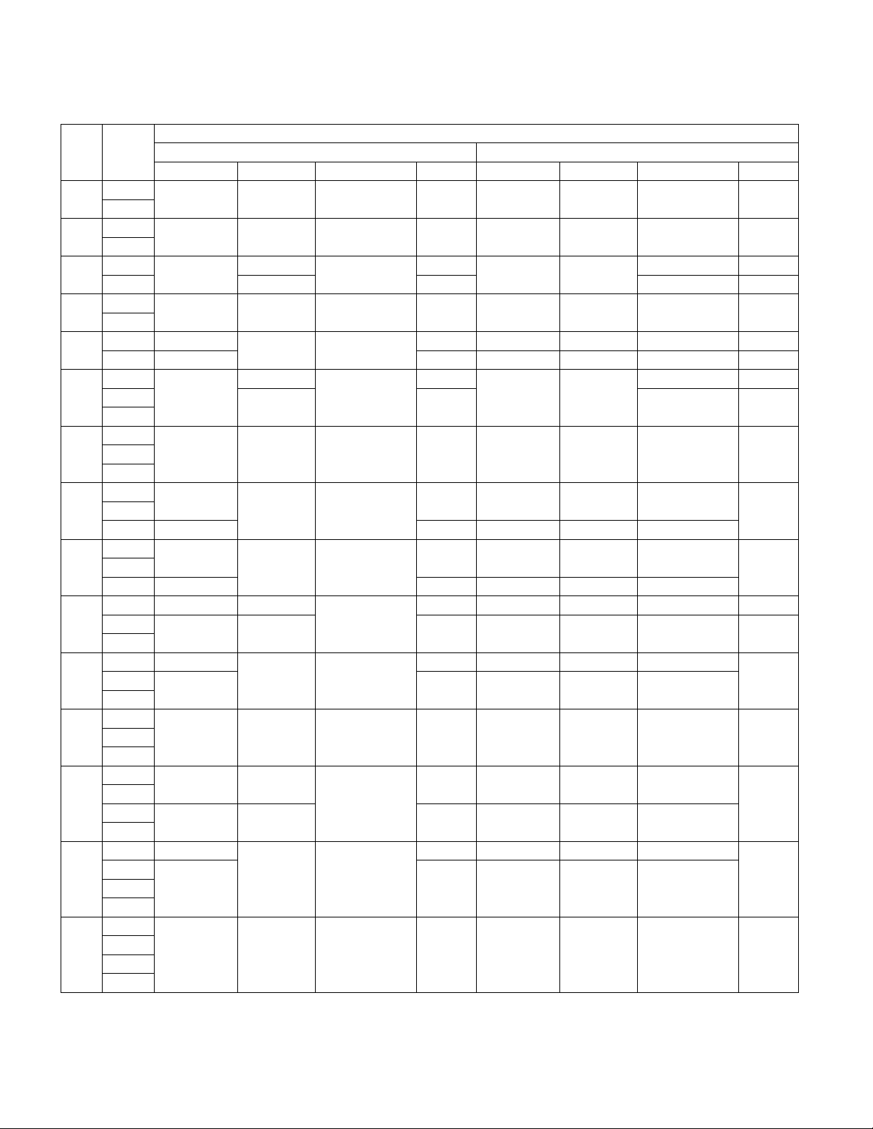
TABLE RP-1 Predetermined Line sizes for Dual Circuit CL units with R-410A
Tons System
45
60
70
75
95
100
110
125
134
135
155
170
190
210
230
1
2
1
2
1
2 1-1/8 in. 1-3/8 in. 7/8 in. 1-3/8 in.
1
2
1 1-5/8 in.
2 2-1/8 in. 1-5/8 in. 2-5/8 in. 1-3/8 in. 1-1/8 in. 1-3/8 in.
1
2
3
1
3
1
3 2-1/8 in. 1-5/8 in. 2-5/8 in. 1-3/8 in. 1-1/8 in.
1
3 2-1/8 in. 1-5/8 in. 2-5/8 in. 1-3/8 in. 1-1/8 in.
1 1-5/8 in. 7/8 in.
2
3
1 1-5/8 in.
3
1
3
1
2
3
4
1 1-5/8 in.
2
3
4
1
2
3
4
Suction Line Liquid Line Hot Gas Bypass Reheat Suction Line Liquid Line Hot Gas Bypass Reheat
1-3/8 in. 7/8 in. 7/8 in. 7/8 in. 1-5/8 in. 7/8 in. 3/4 in. 1-1/8 in.
1-5/8 in. 7/8 in. 7/8 in. 1-1/8 in. 2-1/8 in. 1-1/8 in. 3/4 in. 1-1/8 in.
1-5/8 in.
1-5/8 in. 1-1/8 in. 7/8 in. 1-3/8 in. 2-1/8 in. 1-1/8 in. 7/8 in. 1-3/8 in.
1-5/8 in.
1-5/8 in. 1-1/8 in. 7/8 in. 1-3/8 in. 2-1/8 in. 1-1/8 in. 7/8 in. 1-3/8 in. 2
1-5/8 in.
1-5/8 in.
2-1/8 in. 1-1/8 in. 1-5/8 in. 2-5/8 in. 1-3/8 in. 1-1/8 in. 1-3/8 in.
2-1/8 in. 1-5/8 in. 2-5/8 in. 1-3/8 in. 1-1/8 in.
2-1/8 in. 1-1/8 in. 7/8 in. 1-5/8 in. 2-5/8 in. 1-3/8 in. 1-1/8 in. 1-3/8 in. 2
1-5/8 in. 1-1/8 in.
2-1/8 in. 1-1/8 in. 1-5/8 in. 2-5/8 in. 1-3/8 in. 1-1/8 in.
2-1/8 in. 1-5/8 in. 2-5/8 in. 1-3/8 in. 1-1/8 in.
2-1/8 in. 1-1/8 in. 7/8 in. 1-5/8 in. 2-5/8 in. 1-3/8 in. 1-1/8 in. 1-3/8 in.
Connection Size Predetermined Line Size
7/8 in.
1-1/8 in. 7/8 in.
7/8 in.
1-1/8 in. 1-3/8 in. 7/8 in. 1-3/8 in.
1-1/8 in. 7/8 in.
1-1/8 in. 7/8 in.
1-1/8 in. 7/8 in.
1-1/8 in. 7/8 in.
7/8 in.
7/8 in.
7/8 in.
7/8 in.
R-410A
1-1/8 in.
1-3/8 in. 2-1/8 in. 1-1/8 in. 7/8 in. 1-3/8 in.
1-1/8 in.
1-3/8 in. 2-1/8 in. 1-1/8 in. 7/8 in.
1-3/8 in. 2-1/8 in. 1-1/8 in. 7/8 in.
1-1/8 in. 2-1/8 in. 1-1/8 in. 3/4 in. 1-1/8 in.
1-3/8 in. 2-1/8 in. 1-1/8 in. 7/8 in.
1-3/8 in. 2-1/8 in. 1-1/8 in. 7/8 in.
1-3/8 in. 2-1/8 in. 1-1/8 in. 7/8 in.
2-1/8 in. 1-1/8 in.
2-1/8 in. 1-1/8 in.
3/4 in. 1-1/8 in.
3/4 in. 1-1/8 in.
1-3/8 in. 2
1-3/8 in. 2
1-3/8 in. 2
1-3/8 in.
1-3/8 in.
26
Page 27
REFRIGERANT PIPING cont.
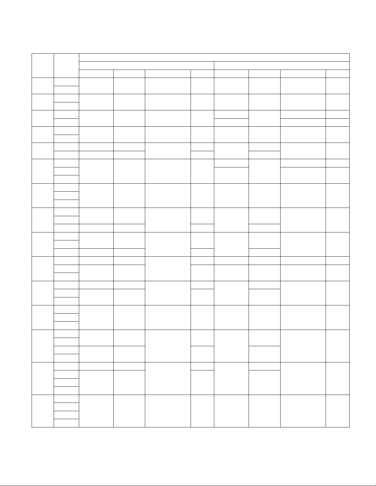
TABLE RP-2 Predetermined Line sizes for Dual Circuit CL units with R-22
Tons System
45
60
70
75
95
100
110
125
134
135
155
170
190
210
230
1
2
1
2
1
2 2-5/8 in. 1-1/8 in. 1-5/8 in.
1
2
1 2-1/8 in. 7/8 in.
2 2-5/8 in. 1-3/8 in. 1-5/8 in. 1-3/8 in.
1
2
3
1
3
1
3 2-5/8 in. 1-3/8 in. 1-5/8 in. 1-3/8 in.
1
3 2-5/8 in. 1-3/8 in. 1-5/8 in. 1-3/8 in.
1 2-1/8 in. 7/8 in.
2
3
1 2-1/8 in. 7/8 in.
3
1
3
1
2
3
4
1 2-1/8 in. 7/8 in.
2
3
4
1
2
3
4
Suction Line Liquid Line Hot Gas Bypass Reheat Suction Line Liquid Line Hot Gas Bypass Reheat
1-3/8 in. 5/8 in. 7/8 in. 7/8 in. 2-1/8 in. 7/8 in. 7/8 in. 1-1/8 in.
2-1/8 in. 7/8 in. 7/8 in. 1-3/8 in. 2-1/8 in. 1-1/8 in. 7/8 in. 1-3/8 in.
2-1/8 in. 7/8 in. 7/8 in. 1-3/8 in.
2-1/8 in. 7/8 in. 7/8 in. 1-3/8 in. 2-5/8 in. 1-1/8 in. 1-1/8 in. 1-5/8 in.
2-1/8 in. 7/8 in. 7/8 in. 1-3/8 in.
2-1/8 in. 7/8 in. 7/8 in. 1-3/8 in. 2-5/8 in. 1-1/8 in. 1-1/8 in. 1-5/8 in. 2
2-1/8 in. 7/8 in.
2-1/8 in. 7/8 in.
2-5/8 in. 1-3/8 in. 1-5/8 in. 2-5/8 in. 1-3/8 in. 1-1/8 in. 1-5/8 in.
2-5/8 in. 1-3/8 in. 1-5/8 in. 1-3/8 in.
2-5/8 in. 1-3/8 in. 7/8 in. 1-5/8 in. 2-5/8 in. 1-3/8 in. 1-1/8 in. 1-5/8 in. 2
2-1/8 in. 7/8 in.
2-5/8 in. 1-3/8 in. 1-5/8 in. 1-3/8 in.
2-5/8 in. 1-3/8 in. 1-5/8 in. 1-3/8 in.
2-5/8 in. 1-3/8 in. 7/8 in. 1-5/8 in. 2-5/8 in. 1-3/8 in. 1-1/8 in. 1-5/8 in.
Connection Size Predetermined Line Size
7/8 in.
7/8 in.
7/8 in.
7/8 in.
7/8 in.
7/8 in.
7/8 in.
R-22
2-1/8 in.
1-3/8 in.
1-3/8 in.
1-3/8 in.
1-3/8 in. 2-1/8 in. 1-1/8 in. 7/8 in. 1-3/8 in.
1-3/8 in.
1-3/8 in.
1-3/8 in.
2-5/8 in.
2-1/8 in.
2-5/8 in. 1-1/8 in. 1-5/8 in.
2-5/8 in.
2-5/8 in.
2-5/8 in.
2-5/8 in.
2-5/8 in.
1-1/8 in.
1-1/8 in.
1-1/8 in.
1-1/8 in.
1-1/8 in.
1-1/8 in.
1-1/8 in.
1-1/8 in.
7/8 in. 1-3/8 in.
1-1/8 in. 1-5/8 in.
7/8 in. 1-3/8 in.
1-1/8 in. 1-5/8 in. 2
1-1/8 in. 1-5/8 in. 2
1-1/8 in. 1-5/8 in. 2
1-1/8 in. 1-5/8 in.
1-1/8 in. 1-5/8 in.
27
Page 28

REFRIGERANT PIPING cont.
TABLE RP-3 Predetermined Line sizes for Single Circuit CL units with R-410A
Tons System
Suction Line Liquid Line Hot Gas Bypass Reheat Suction Line Liquid Line Hot Gas Bypass Reheat
1
45
60
70
75
95
2
3
4
1
2
3
4
1 1-3/8 in.
2 1-5/8 in. 1-5/8 in. 7/8 in. 1-1/8 in.
3 1-3/8 in. 1-3/8 in. 3/4 in. 7/8 in.
4 1-5/8 in. 1-5/8 in. 7/8 in. 1-1/8 in.
1
2
3
4
1
2 7/8 in. 1-1/8 in. 2-1/8 in. 1-1/8 in. 7/8 in.
3 5/8 in. 7/8 in. 1-5/8 in. 7/8 in. 3/4 in.
4 7/8 in. 1-1/8 in. 2-1/8 in. 1-1/8 in. 7/8 in.
TABLE RP-4 Predetermined Line sizes for Single Circuit CL units with R-22
Tons System
Suction Line Liquid Line Hot Gas Bypass Reheat Suction Line Liquid Line Hot Gas Bypass Reheat
1
45
60
70
75
95
2
3
4
1
2
3
4
1
2 2-1/8 in.
3 1-5/8 in.
4 2-1/8 in.
1
2
3
4
1 1-3/8 in. 5/8 in.
2 2-1/8 in. 7/8 in. 1-3/8 in. 1-1/8 in. 1-1/8 in. 1-3/8 in.
3 1-3/8 in. 5/8 in. 7/8 in. 3/4 in. 7/8 in. 1-1/8 in.
4 2-1/8 in. 7/8 in. 1-3/8 in. 1-1/8 in. 1-1/8 in. 1-3/8 in.
1-1/8 in. 5/8 in. 7/8 in. 7/8 in. 1-3/8 in. 5/8 in. 5/8 in. 3/4 in.
1-3/8 in. 5/8 in. 7/8 in. 7/8 in. 1-3/8 in. 3/4 in. 3/4 in. 7/8 in.
1-5/8 in. 5/8 in. 7/8 in. 7/8 in. 1-5/8 in. 7/8 in. 3/4 in. 1-1/8 in.
1-5/8 in.
1-3/8 in. 5/8 in. 7/8 in. 7/8 in. 1-5/8 in. 5/8 in. 3/4 in. 7/8 in.
1-3/8 in. 5/8 in. 7/8 in. 7/8 in. 1-5/8 in. 3/4 in. 7/8 in. 1-1/8 in.
1-3/8 in. 5/8 in. 7/8 in. 7/8 in.
1-3/8 in. 5/8 in. 7/8 in. 7/8 in. 2-1/8 in. 3/4 in. 7/8 in. 1-1/8 in.
Connection Size Predetermined Line Size
5/8 in. 7/8 in. 7/8 in.
5/8 in.
Connection Size Predetermined Line Size
7/8 in.
7/8 in.
R-410A
1-3/8 in. 3/4 in.
7/8 in. 1-5/8 in. 7/8 in. 3/4 in.
R-22
1-5/8 in.
3/4 in. 7/8 in. 1-1/8 in.
7/8 in.
2-1/8 in.
3/4 in. 7/8 in. 1-1/8 in.
7/8 in.
3/4 in.
1-1/8 in.
28
Page 29
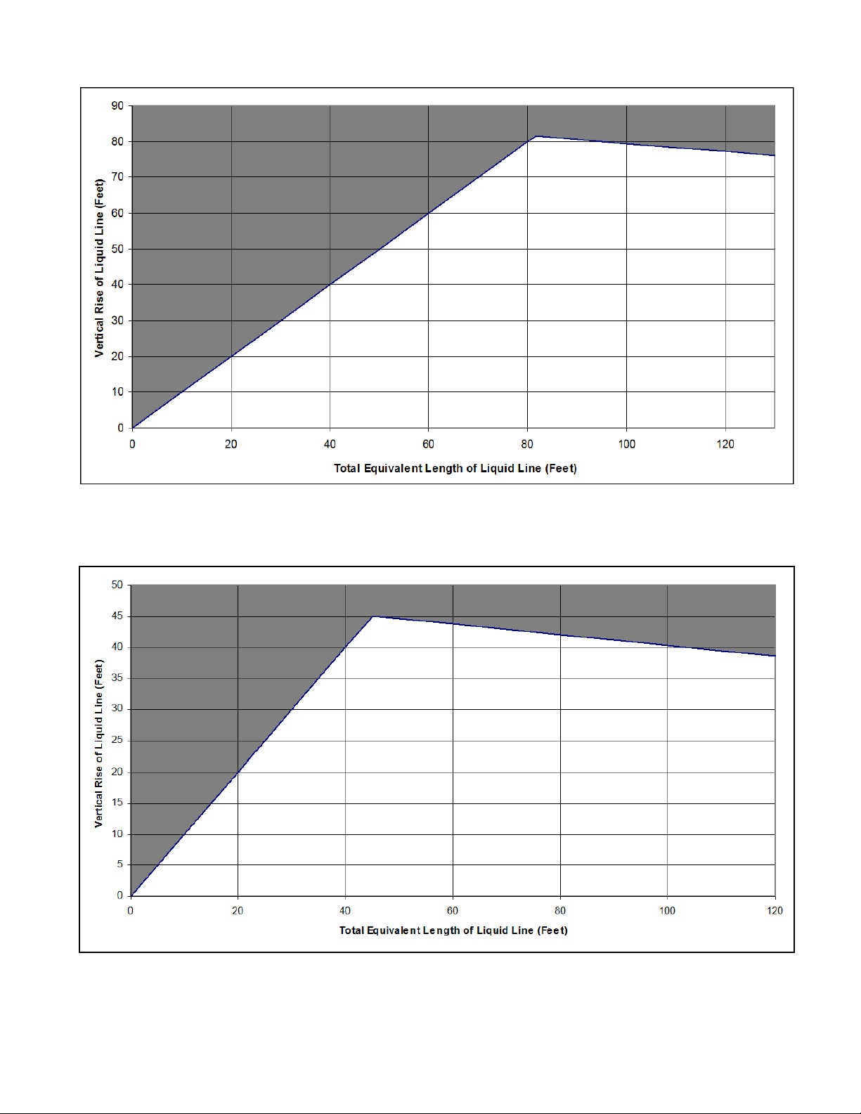
REFRIGERANT PIPING cont.
Acceptable Region
FIGURE RP-1. Riser height versus total equivalent line length for R-410A split system applications with
dual circuited CL-045 through CL-230 units. The region of acceptable riser height is the lighter area.
Select the corresponding predetermined line size from TABLE RP-1 on page 26.
Acceptable Region
FIGURE RP-2. Riser height versus total equivalent line length for R22 split system applications with dual
circuited CL-045 through CL-230 units. The region of acceptable riser height is the light area. Select the
corresponding predetermined line size from TABLE RP-2 on page 27.
29
Page 30
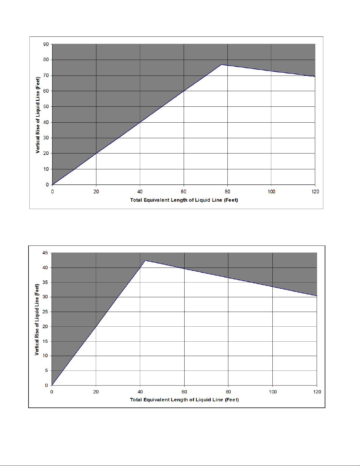
REFRIGERANT PIPING cont.
Acceptable Region
FIGURE RP-3. Riser height versus total equivalent line length for R-410A split system applications with
single circuited CL-045 through CL-230 units. The region of acceptable riser height is the lighter area.
Select the corresponding predetermined line size from TABLE RP-3 on page 28.
Acceptable Region
FIGURE RP-4. Riser height versus total equivalent line length for R22 split system applications with
single circuited CL-045 through CL-230 units. The region of acceptable riser height is the light area.
Select the corresponding predetermined line size from TABLE RP-4 on page 28.
30
Page 31
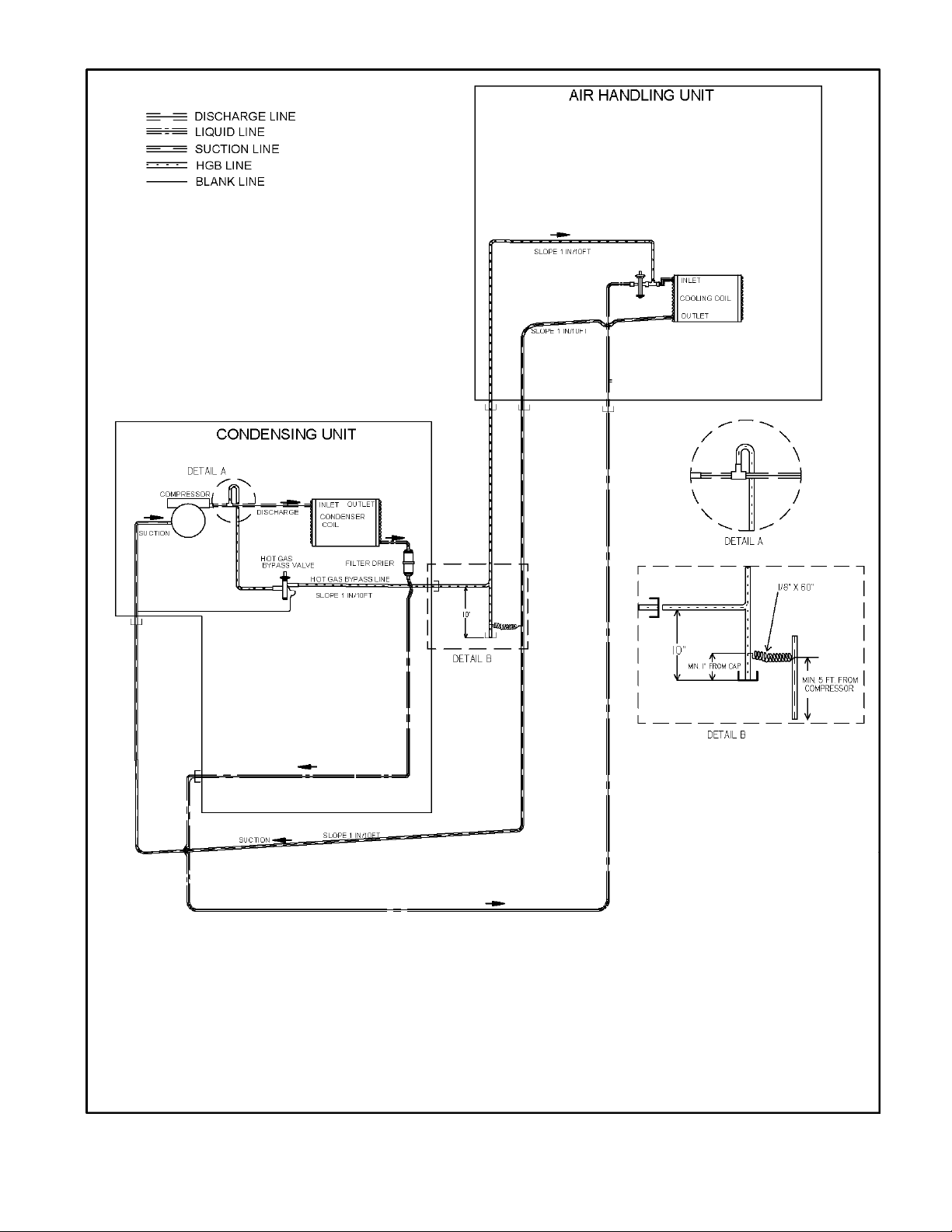
Note: Components shown within air
handler and condensing unit are factory
installed; all other components are field
installed.
FIGURE RP-2. Hot Gas Bypass Piping Diagram with air handler above condenser.
31
Page 32

32
Note: Components shown within air
handler and condensing unit are factory
installed; all other components are field
installed.
FIGURE RP-3. Hot Gas Bypass Piping Diagram with air handler below condenser.
Page 33

Note: Components shown within air
handler and condensing unit are factory
installed; all other components are field
installed.
FIGURE RP-4. Hot Gas Reheat Piping Diagram with air handler above condenser.
33
Page 34

34
Note: Components shown within air
handler and condensing unit are factory
installed; all other components are field
installed.
FIGURE RP-5. Hot Gas Reheat Piping Diagram with air handler below condenser.
Page 35
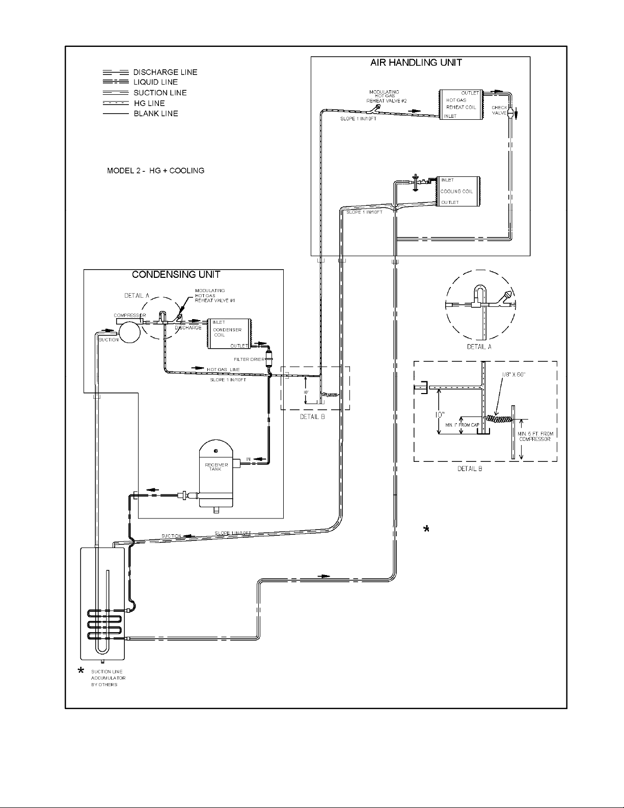
TO BE INSTALLED IN FIELD
Note: Components shown within air
handler and condensing unit are factory
installed; all other components are field
installed.
FIGURE RP-6. Hot Gas Reheat Piping Diagram with air handler above condenser and field installed
suction line accumulator.
35
Page 36

Note: Components shown within air
handler and condensing unit are factory
TO BE INSTALLED IN FIELD
installed; all other components are field
installed.
FIGURE RP-7. Hot Gas Reheat Piping Diagram with air handler above condenser and field installed
suction line accumulator.
36
Page 37

Note: Components shown within air
handler and condensing unit are factory
installed; all other components are field
installed.
FIGURE RP-8. Reheat/Hot Gas Bypass Piping Diagram with air handler above condenser.
37
Page 38

38
Note: Components shown within air
handler and condensing unit are factory
installed; all other components are field
installed.
FIGURE RP-9. Reheat/Hot Gas Bypass Piping Diagram with air handler below condenser.
Page 39

TO BE INSTALLED IN FIELD
TO BE INSTALLED IN FIELD
Note: Components shown within air
handler and condensing unit are factory
installed; all other components are field
installed.
FIGURE RP-10. Reheat/Hot Gas Bypass Piping Diagram with air handler evaporator above condenser
and field installed suction line accumulator.
39
Page 40

Note: Components shown within air
handler and condensing unit are factory
installed; all other components are field
TO BE INSTALLED IN FIELD
installed.
FIGURE RP-11. Reheat/Hot Gas Bypass Piping Diagram with air handler below condenser and field
installed suction line accumulator.
40
Page 41

Note: Components shown within air
handler and condensing unit are factory
installed; all other components are field
installed.
FIGURE RP-5. Hot Gas Bypass Piping Diagram with air handler above condenser.
41
Page 42
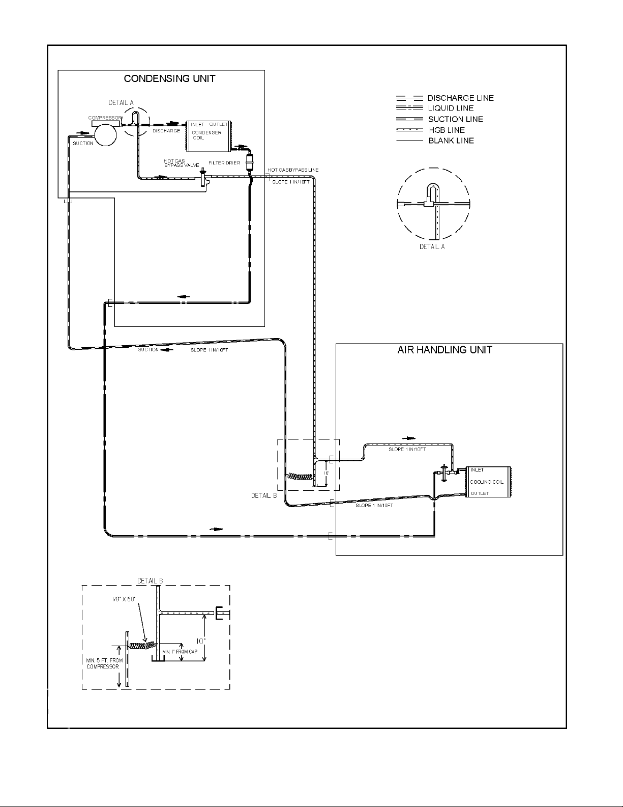
42
Note: Components shown within air
handler and condensing unit are factory
installed; all other components are field
installed.
FIGURE RP-6. Hot Gas Bypass Piping Diagram with air handler below condenser.
Page 43
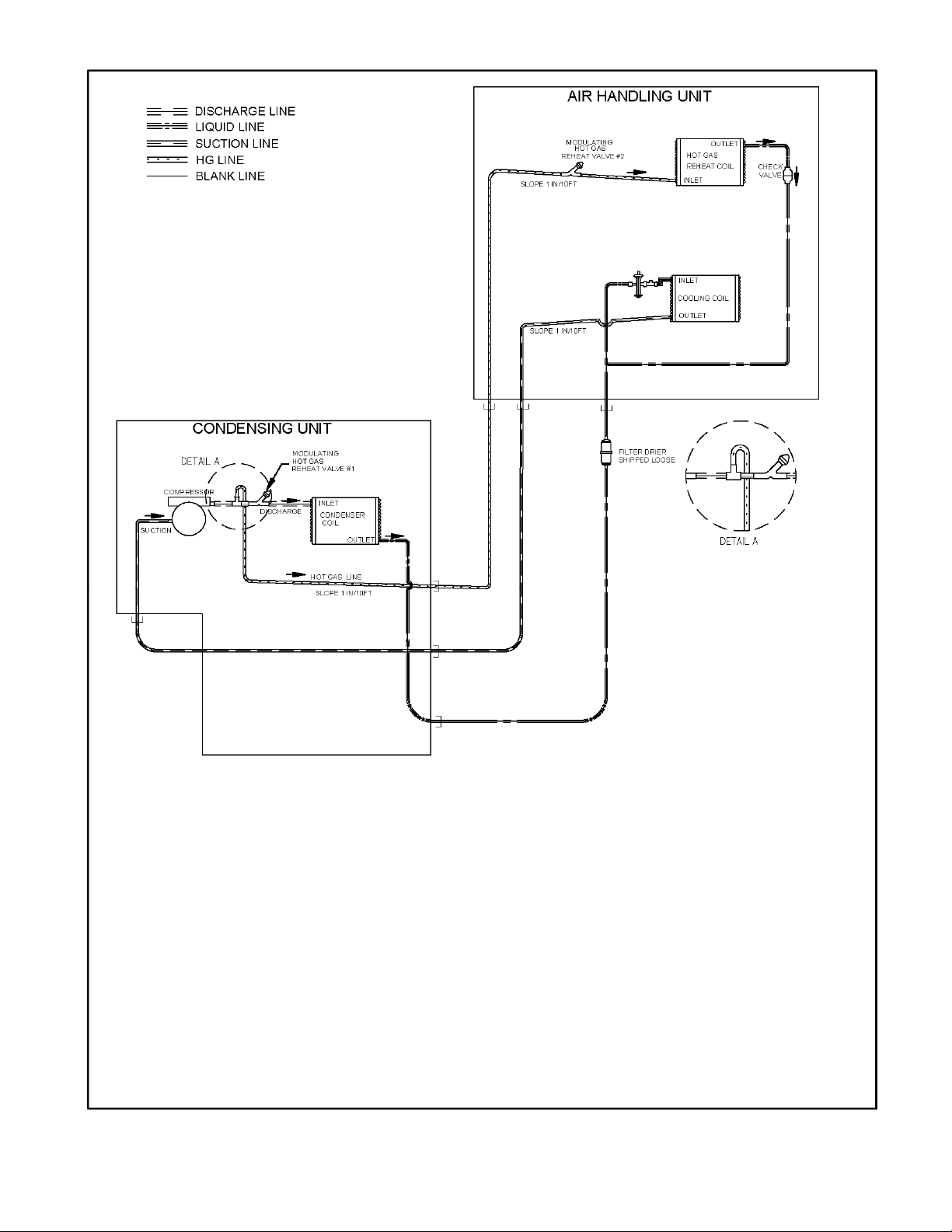
Note: Components shown within air
handler and condensing unit are factory
installed; all other components are field
installed.
FIGURE RP-7. Hot Gas Reheat Piping Diagram with air handler above condenser.
43
Page 44

44
Note: Components shown within air
handler and condensing unit are factory
installed; all other components are field
installed.
FIGURE RP-8. Hot Gas Reheat Piping Diagram with air handler below condenser.
Page 45

TO BE INSTALLED IN FIELD
Note: Components shown within air
handler and condensing unit are factory
installed; all other components are field
installed.
FIGURE RP-9. Hot Gas Reheat Piping Diagram with air handler above condenser and field installed
suction line accumulator.
45
Page 46
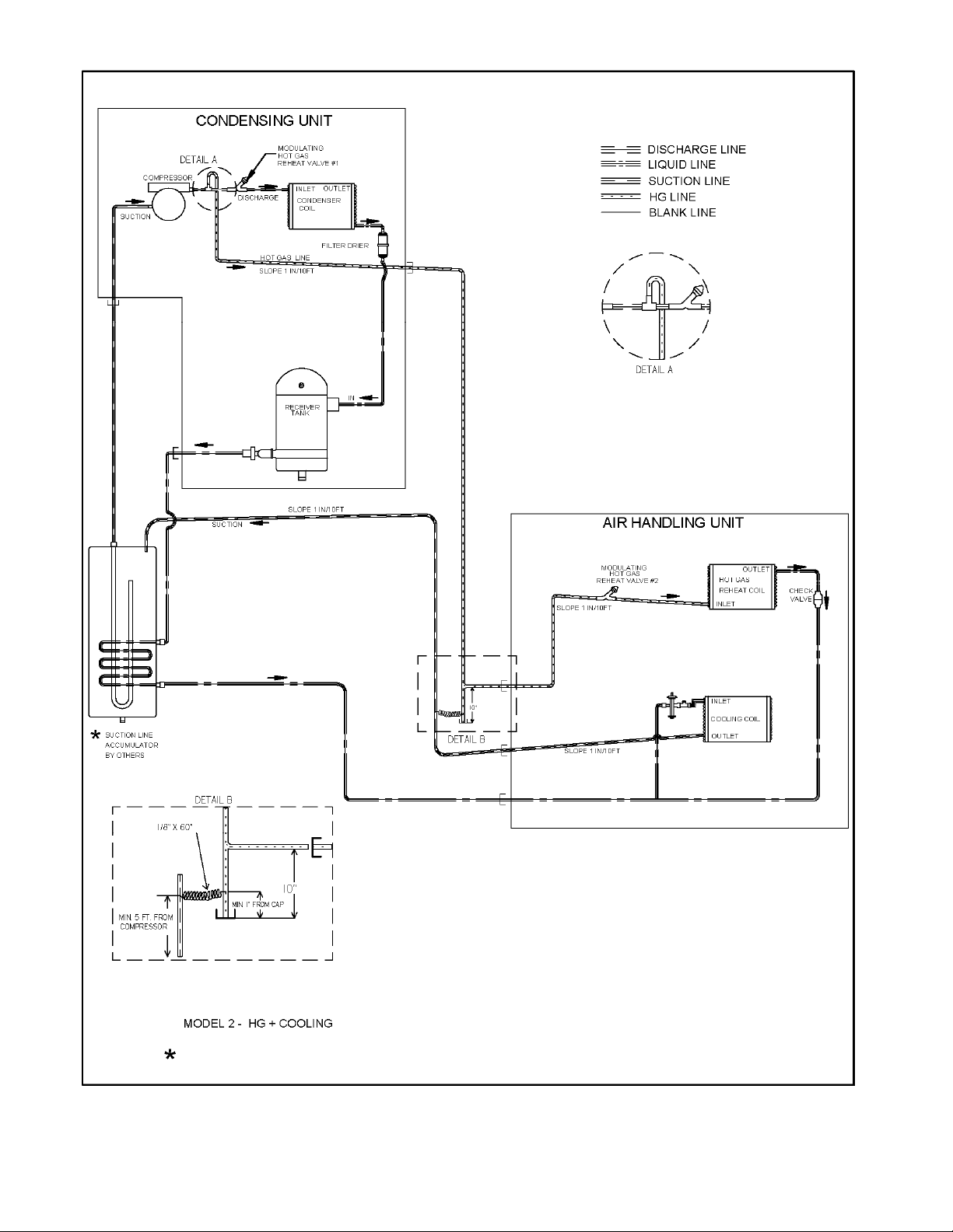
Note: Components shown within air
handler and condensing unit are factory
TO BE INSTALLED IN FIELD
installed; all other components are field
installed.
FIGURE RP-10. Hot Gas Reheat Piping Diagram with air handler above condenser and field installed
suction line accumulator.
46
Page 47
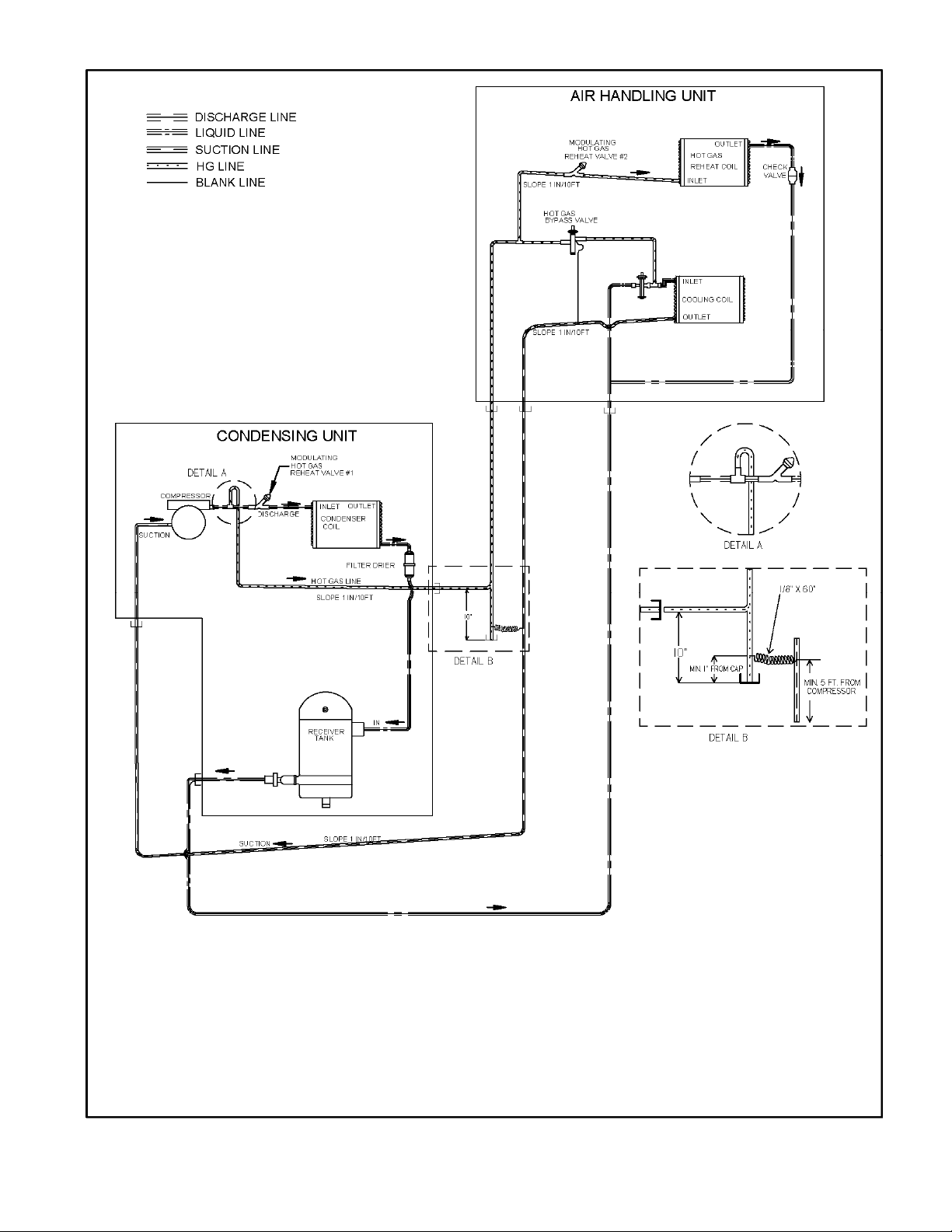
Note: Components shown within air
handler and condensing unit are factory
installed; all other components are field
installed.
FIGURE RP-11. Reheat/Hot Gas Bypass Piping Diagram with air handler above condenser.
47
Page 48

48
Note: Components shown within air
handler and condensing unit are factory
installed; all other components are field
installed.
FIGURE RP-12. Reheat/Hot Gas Bypass Piping Diagram with air handler below condenser.
Page 49
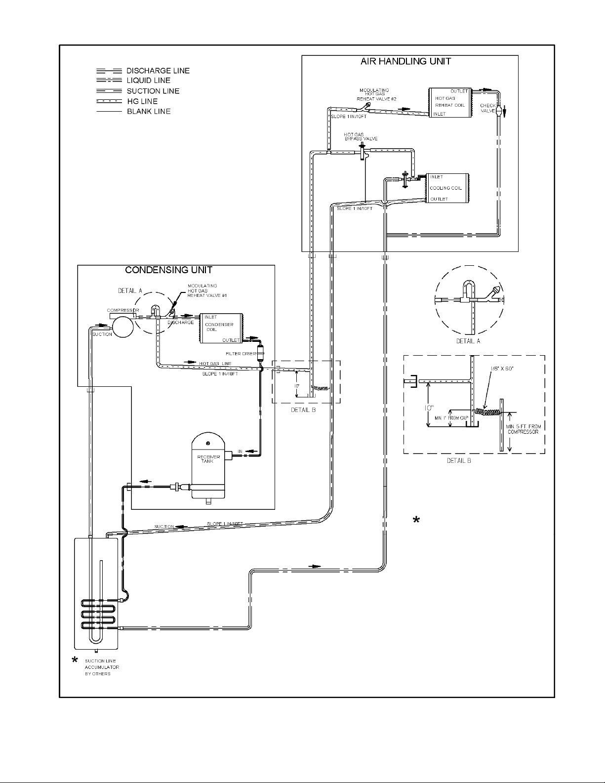
TO BE INSTALLED IN FIELD
Note: Components shown within air
handler and condensing unit are factory
installed; all other components are field
installed.
FIGURE RP-13. Reheat/Hot Gas Bypass Piping Diagram with air handler evaporator above condenser
and field installed suction line accumulator.
49
Page 50

Note: Components shown within air
handler and condensing unit are factory
installed; all other components are field
TO BE INSTALLED IN FIELD
installed.
FIGURE RP-14. Reheat/Hot Gas Bypass Piping Diagram with air handler below condenser and field
installed suction line accumulator.
50
Page 51
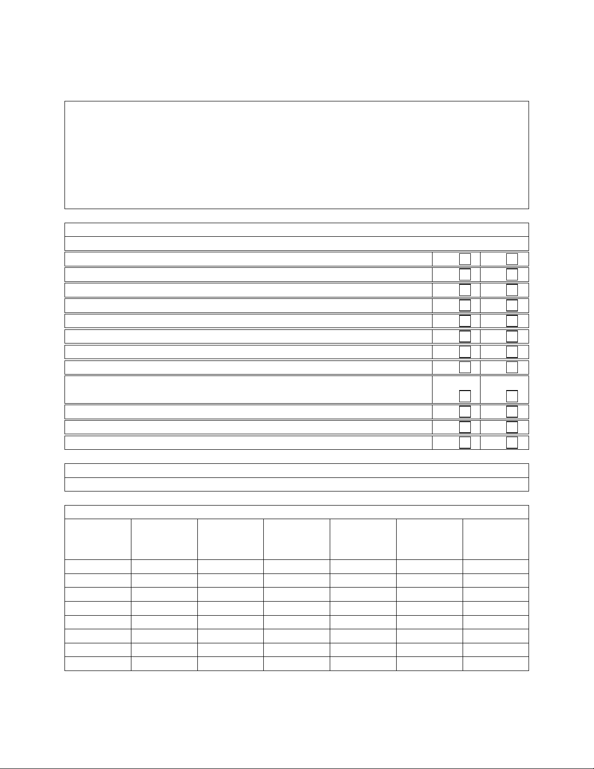
Condenser and Condenser Unit Startup Form
Date:______________
Job Name:_____________________________________________________________________
Address:______________________________________________________________________
Model Number:_________________________________________________________________
______________________________________________________________________________
Serial Number:_____________________________________________ Tag:_______________
Startup Contractor:______________________________________________________________
Address:__________________________________________________ Phone:_____________
Pre Startup Checklist
1. Is there any visible shipping damage? Yes No
2. Is the unit level? Yes No
3. Are the unit clearances adequate for service and operation? Yes No
4. Do all access doors open freely and are the handles operational? Yes No
5. Have all shipping braces been removed? Yes No
6. Have all electrical connections been tested for tightness? Yes No
7. Does the electrical service correspond to the unit nameplate? Yes No
8. On 208/230V units, has transformer tap been checked? Yes No
9. Has overcurrent protection been installed to match the unit nameplate
requirement? Yes No
10. Have all set screws on the fans been tightened? Yes No
11. Do all fans and pumps rotate freely? Yes No
12. Is all copper tubing isolated so that it does not rub? Yes No
Ambient Temperature
Ambient Dry Bulb Temperature ________°F Ambient Wet Bulb Temperature ________°F
Compressors / DX Cooling
Compressor
Number L1 L2 L3
1
2
3
4
5
6
7
8
Installing contractor should verify the following items.
Head
Pressure
PSIG
Suction
Pressure
PSIG
Crankcase
Heater
Amps
Page 52

Refrigeration System 1
Discharge
Suction
Liquid
Pressure
Saturated
Temperature
Line
Temperature
Sub-cooling Superheat
N/A N/A
N/A
N/A
Refrigeration System 2
Discharge
Suction
Liquid
Pressure
Saturated
Temperature
Line
Temperature
Sub-cooling Superheat
N/A N/A
N/A
N/A
Refrigeration System 3
Pressure
Saturated
Temperature
Line
Temperature
Sub-cooling Superheat
Discharge N/A N/A
Suction N/A
Liquid N/A
Refrigeration System 4
Pressure
Saturated
Temperature
Line
Temperature
Sub-cooling Superheat
Discharge N/A N/A
Suction N/A
Liquid N/A
Condenser Fans
Alignment
Check Rotation
Nameplate Amps________
Number hp L1 L2 L3
1
2
3
4
5
6
Condenser Pump
Check Rotation
Nameplate Amps________
Number hp L1 L2 L3
1
2
Page 53
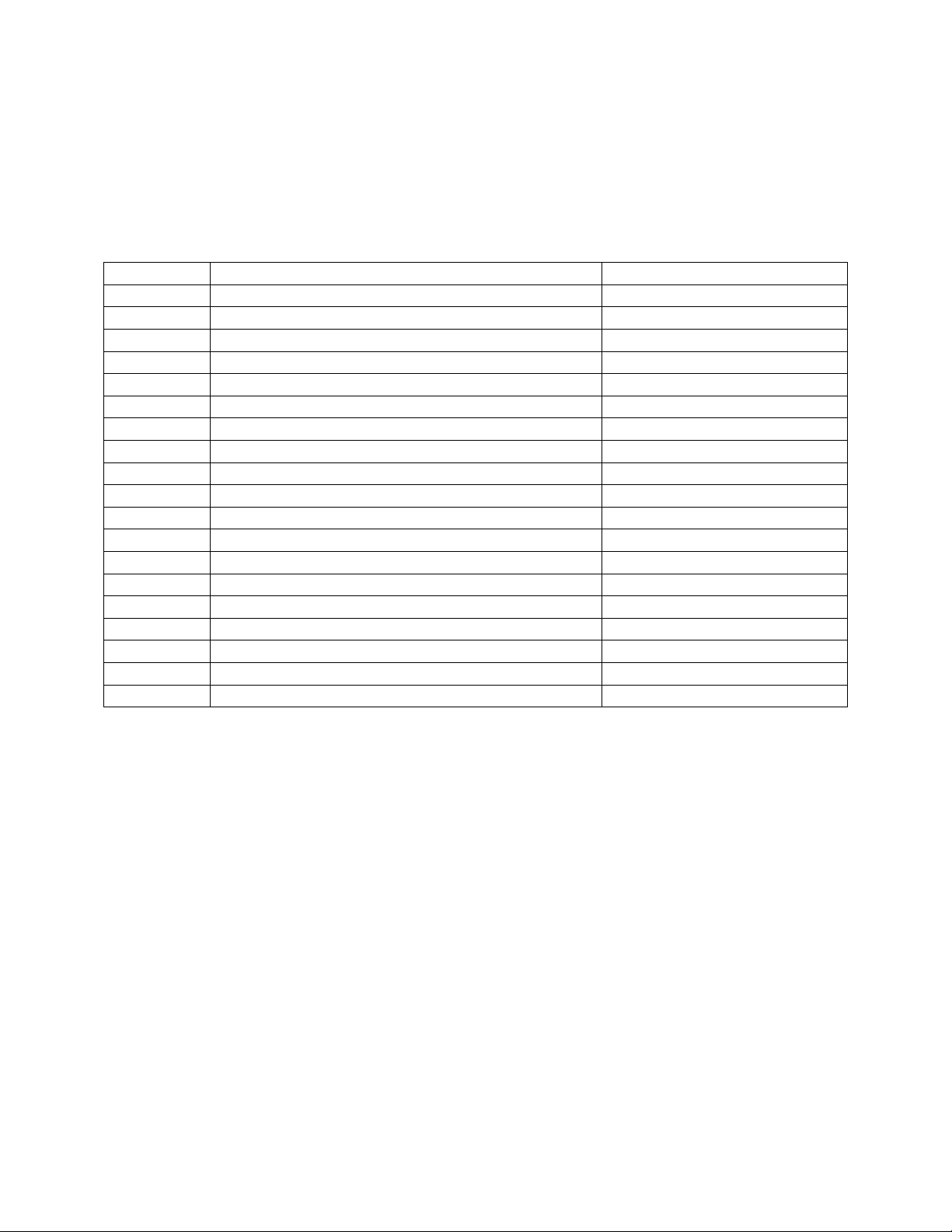
Maintenance Log
This log must be kept with the unit. It is the responsibility of the owner and/or
maintenance/service contractor to document any service, repair or adjustments. AAON Service
and Warranty Departments are available to advise and provide phone help for proper operation
and replacement parts. The responsibility for proper start-up, maintenance and servicing of the
equipment falls to the owner and qualified licensed technician.
Entry Date Action Taken Name/Tel.
Page 54

CL SERIES CONDENSING
UNIT
•
INSTALLATION, SERVICE
&
OWNERS INFORMATION MANUAL
AAON, Inc.
2425 South Yukon
Tulsa, Oklahoma 74107
Phone: (918) 583-2266 • Fax: (918) 583-6094
R10110 · Rev. B · 4-07
 Loading...