

Page 1
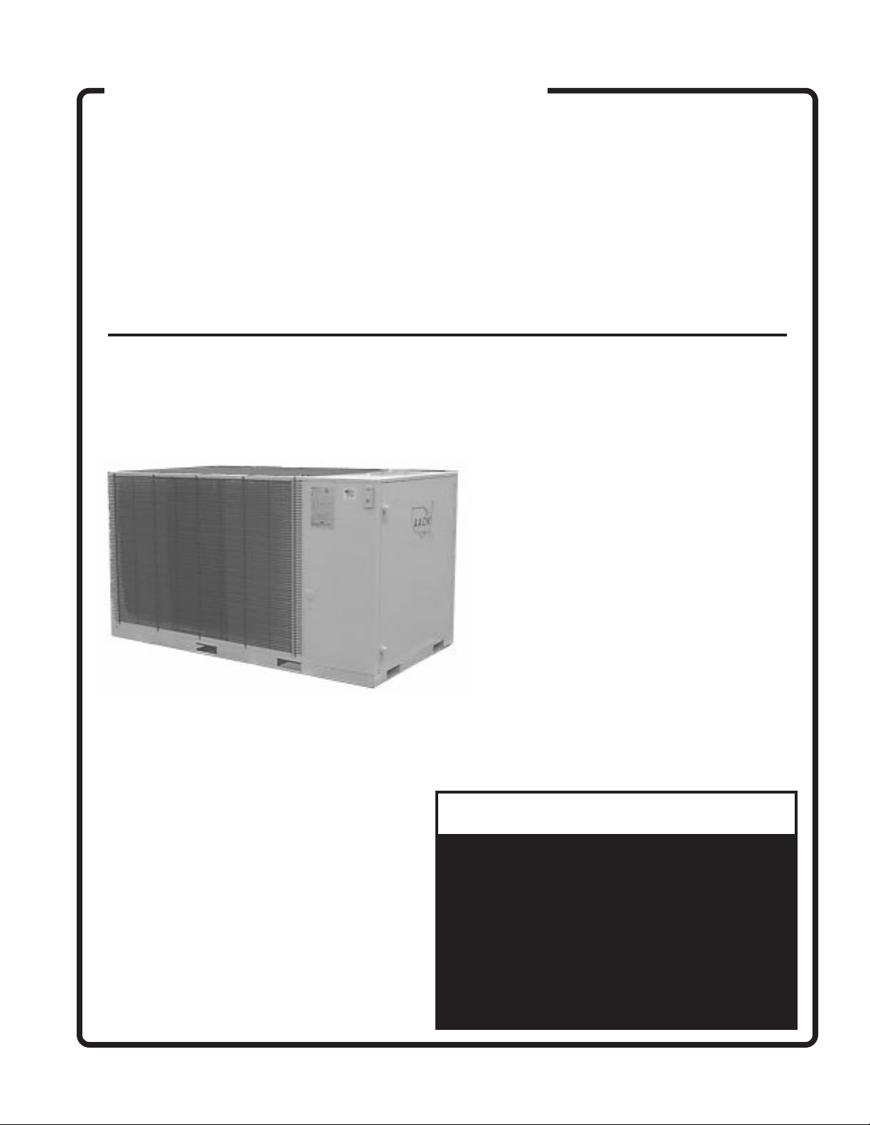
AAON Coil Products
CONDENSING UNITS
INSTALLATION
CA SERIES
AND
MANUFACTURED
IN THE U.S.A
OPERATION
MANUAL
!
▲
Scroll compressors will be damaged by
operation with the wrong rotation.
THE LOW PRESSURE SWITCH HAS BEEN
DISCONNECTED AFTER TESTING
The wiring must be reconnected and proper
rotation determined at the time of start-up by
a qualified service technician using suction
and discharge pressures gauges.
Any alteration should only be made at
the unit power connection.
WARNING
AT THE FACTORY.
1
Page 2
AAON Coil Products
SECTION PAGE NUMBER
INSTALLATION ……………………………………………………………………………3
General
Location
Service Clearance
Setting the Unit
Electrical
Thermostat
REFRIGERANT PIPING
General …………………………………………………………………………4
Interconnecting Piping
CHECKOUT PROCEDURE …………………………………………………………… 6
Cooling
Compressor Checkout Procedure ……………………………………… 7
SERVICE, TROUBLE SHOOTING & MAINTENANCE …………………………………8
General Instructions
Coil Information
TABLE OF CONTENTS
! IMPORTANT
▲
The Clean Air Act of 1990 bans the intentional
!
▲
Installation and service must be performed by
a qualified installer or service agency.
Owner should pay particular attention to the words: NOTE, CAUTION AND WARNING.
NOTES are intended to clarify or make the installation easier. CAUTIONS are given to prevent
equipment damage. WARNINGS are given to alert owner that personal injury and/or equipment
It is the intent of
However, in the interest of product improvement,
P84510-A
(ACP 27230)
CAUTION
damage may result if installation procedure is not handled properly.
AAON Coil Products, Inc.
and/or design of it's products without notice, obligation or liability.
© 1999
AAON Coil Products, Inc.
to provide accurate and current specification information.
AAON Coil Products, Inc.
, all rights reserved throughout the world.
venting of refrigerant (CFC's and HCFC's) as of
July 1, 1992. Approved methods of recovery,
recycling or reclaiming must be followed.
Fines and/or incarceration may be levied for
non-compliance.
reserves the right to change pricing, specifications
2
Page 3

INSTALLATION
AAON Coil Products 'CA' Series units are designed for fast easy installation
GENERAL
All CA condensing units have lifting areas at the underside of the equipment to allow moving and placement
without physical damage. Arrange spreader bars,
blocking or other lifting devices to prevent any damage to the coils or cabinet of the condensing unit.
These condensing units may be placed on a roof or at
ground level since they are designed for exposure to
weather.
When roof mounted, a steel frame must be provided
that will support the unit above the roof itself.
When installed at ground level, a substantial base must
be provided that will not settle.
LOCATION
Airflow to and from the condensing unit must not be
restricted. Obstruction to air flow will result in decreased performance and efficiency. The installation
position must provide at least 3 feet of side clearance
for proper air flow into the coils. When units are
mounted adjacent to each other the clearance required between them would be 6 feet.
Condensing units should not be installed in an enclosure or pit that is deeper than the height of the unit.
When a recessed installation is used the side clearance requirement is doubled to 6 feet for the inlet air.
The CA 02 through CA 05 model sizes have a horizontal
airflow pattern. The discharge air side of one unit
should not be aligned with the intake of another. The
discharge air should be faced away from the adjacent building or structure.
The CA 08 through CA 25 models have a vertical air
discharge. There must be no obstruction above the
equipment that may deflect this air back to the inlet of
the condensing unit. Do not place the unit under an
overhang.
Condensing unit operation can also be affected by
wind. It is good practice to position the unit so its length
is parallel with the prevailing wind.
SERVICE CLEARANCE
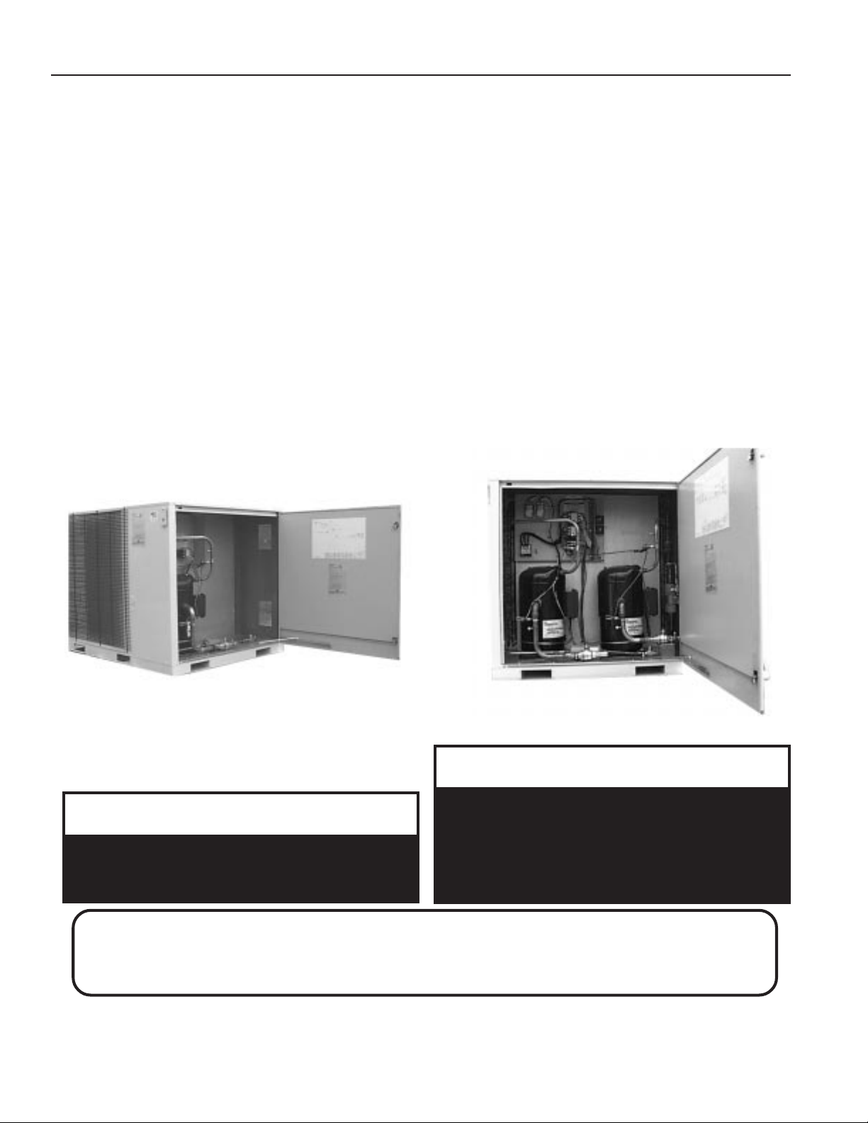
One end of the CA condensing unit contains the
access door that must be accessible for periodic
service. This area contains the compressor, controls,
safety devices, refrigerant service and shut-off valves.
It is recommended that a minimum of 4 feet be left free
at this end of the unit for proper and easier servicing.
SETTING THE UNIT
If cables or chains are used to hoist the unit, care
should be taken to prevent damage to the cabinet.
Hoist unit to a point directly above the pad, and lower
unit into the proper place. Unit may also be positioned
with a forktruck. Remove the harness used in hoisting.
Make sure the unit is properly seated and level.
ELECTRICAL
Check the unit data plate to make sure it agrees with
the power supply. Connect power to the unit according to the wiring diagram provided with the unit.
The power and control wiring may be brought in
through the holes provided at one corner of the unit.
Protect the branch circuit in accordance with code
requirements. If the control wires are to run inside the
same conduit, use 600 volt wire or as required by
applicable codes. The unit must be electrically
grounded in accordance with the National Electric
Code, ANSI / NFPA No. 70-1984 when installed if an
external source is utilized, in Canada use current C.S.A.
Standard C22.1 Canadian Electric Code Part 1.
Power wiring is to the unit terminal block or compressor
contactor. All wiring beyond this point has been done
by the manufacturer.
Connect the control wiring and apply power to the unit.
CHECK COMPRESSOR FOR PROPER ROTATION BY STARTING UNIT ONLY AFTER CONNECTING PRESSURE GAUGES
TO SUCTION AND DISCHARGE.
THE COMPRESSOR WILL BE DESTROYED IF RUN IN THE
WRONG DIRECTION.
NOTE: All units are factory wired for 230, 380, 415, 460
or 575 volt.
THERMOSTAT
Low voltage room thermostat should be located on an
inside wall 4 to 5 feet above the floor where it will not
be subjected to drafts, sun exposure or heat from
electrical fixtures or appliances. Follow manufacturer's
instructions enclosed with thermostat for general installation procedure.
! IMPORTANT
▲
Three phase Scroll Compressors are directional
and start-up must be performed by a qualified
service technician using suction and discharge
gauges.
!
▲
WARNING
Electric shock hazard. Can cause injury or death.
Before attempting to perform any service or
maintenance, turn the electrical power to unit to
OFF at disconnect switch(es). Unit may have
multiple power supplies.
3
Page 4

REFRIGERANT PIPING
GENERAL
All refrigeration systems are factory assembled, including a holding charge of R-22, and tested. On 13 - 25 ton
units the refrigerant system includes dual condenser
coils providing two stage cooling. These systems are
provided with liquid line filter driers and fully hermetic
compressors. Compressors are equipped with a positive pressure forced lubrication system and crankcase
heater. The air cooled condenser coil(s) is constructed
of copper tubes with aluminum fins (copper fins optional), the air is pulled through with steel propeller
fans.
All CA Condensing units have factory furnished liquid
and suction line shutoff valves. The pipe sizes must be
selected to meet the actual installation conditions
and not simply based on the connection sizes at the
evaporator and/or condensing unit.
The refrigeration section of these appliances has been
listed by E.T.L. as meeting the applicable provisions of
UL 1995, CAN/CSA C22.2, No. 236-Second Edition.
NOTE: Crankcase Heater Operation
The 8 through 25 ton sizes are equipped with a crankcase heater, which should be energized at least 24
hours prior to setting the thermostat for cooling operation with the compressor.
This section is not intended to provide all the information required by the designer or installer of the refrigerant piping between the condensing units and the low
side components. The appropriate sections of the
ASHRAE Guide and the ASME standards should be
used for final information.
! IMPORTANT
▲
The Clean Air Act of 1990 bans the intentional
venting of refrigerant (CFC's and HCFC's) as of
July 1, 1992. Approved methods of recovery,
recycling or reclaiming must be followed.
Fines and/or incarceration may be levied for
non-compliance.
• once piped, the interconnecting piping and air
handler MUST BE evacuated to 50 microns or less;
leak checked and charged with R22 refrigerant.
• open the shut off valves.
• run unit, check rotation of compressors using
refrigerant gauges.
• check super heat and subcooling; subcooling
should be 10-13°F, evaporator superheat should
be 10-15 °F. Also check the compressor discharge
line superheat. It should be at least 60°F.
• make sure airhandler thermal expansion valve
bulb is mounted with good thermal contact on
the correct suction line on a horizontal section,
close to the evaporator in the 4 or 8 o'clock
position and insulated.
• the suction line should be insulated for its entire
length.
SUCTION LINE
The suction line pipe size should be selected to have
a maximum pressure drop of 3 PSI for the equivalent
length of piping that is used. This corresponds to
approximately 2°F with R22.
The piping between the condenser and low side must
assure:
• minimum pressure drop
• continuous oil return
• prevention of liquid refrigerant slugging or carryover.
Acceptable system design and installation will include
consideration as follows:
Interconnecting Piping Summary
• piping from the condensing unit to the indoor air
handler is the responsibility of the installing contractor.
• only clean "ACR" tubing should be used.
• condensing units are provided with in-line shutoff
valves on both the liquid and suction lines. These
should remained closed until the system is ready
for start-up.
• piping should conform to generally accepted
practices and codes.
• care must be taken not to cross the circuits on
multiple circuit systems.
Any vertical suction risers should be checked to confirm that oil will be returned to the compressor. (Use
the following tables for pipe sizing information).
All suction lines must be pitched in the direction of flow
and supported to maintain their position.
Fully insulated piping must be used between the
evaporator and the condensing unit. A suction accumulator is not included as part of the CA condensing
unit and must be field furnished and installed if required by job conditions.
R22 SUCTION LINE CAPACITY
Pressure Loss = 3 PSI (2°F) at 40°F saturated suction
LINE SIZE - inches MAX. TONS / COMPRESSOR
5/8" 1.1
7/8" 2.9
1 1/8" 5.8
1 3/8" 10.1
1 5/8" 16.0
NOTE: Pressure loss, PSI/100 feet of equivalent line length
due to line friction. (Corresponding change in R22 saturation temperature.)
4
Page 5

LIQUID LINE
The liquid line pipe size should be selected to have a
maximum pressure drop of 6 PSI which corresponds to
approximately 2°F with R22.
The CA condensing units have a built in filter drier. The
units do not include a liquid line solenoid valve and this
must be field furnished and installed if required by job
conditions.
(OPTIONAL) HOT GAS LINE
The hot gas bypass option is a system that maintains
evaporator pressure at or above a minimum value.
This will prevent the coil from freezing and also keep
the velocity of the refrigerant gas sufficiently high for
proper oil return to the compressor when the cooling
is at light load conditions.
Pressure drop in the hot gas line is normally designed
not to exceed the equivalent of a 2°F change in
saturation temperature. The recommended sizing
table below is based on a 1°F change in saturation
temperature.
Hot gas bypass lines must be insulated to minimize
heat loss and condensation of gas inside the piping
and to prevent injury from high temperature surfaces.
R22 LIQUID LINE CAPACITY
Pressure Loss = 3 PSI (1°F) at 100°F liquid
MINIMUM TONS CAPACITY
To Carry Oil Up a Suction Riser at 40°F saturated suction
LINE SIZE - inches Min. TONS / COMPRESSOR
3/4" 0.8
7/8" 1.1
1 1/8" 1.8
1 3/8" 2.9
1 5/8" 4.0
2 1/8" 7.2
FITTING LOSSES
In Equivalent Feet of Straight Copper Tubing
Line
Size - in.
90°
Std.
90°
LongRad
90°
Street
45°
Std.
45°
Street
180°
Std.
1/2" 1.4 0.9 2.3 0.7 1.1 2.3
5/8" 1.6 1.0 2.5 0.8 1.3 2.5
7/8" 2.0 1.4 3.2 0.9 1.6 3.2
1 1/8" 2.6 1.7 4.1 1.3 2.1 4.1
1 3/8" 3.3 2.3 5.6 1.7 3.0 5.6
1 5/8" 4.0 2.6 6.3 2.1 3.4 6.3
2 1/8" 5.0 3.3 8.2 2.6 4.5 8.2
NOTE: The equivalent feet for a piping system must include
the equivalent length of straight tubing for all the fittings, as
well as, any valves that are added to the system.
LINE SIZE - inches MAX. TONS / COMPRESSOR
1/2" 3.6
5/8" 6.7
7/8" 18.2
NOTE: Pressure loss, PSI/100 feet of equivalent line length
due to line friction. (Corresponding change in R22 saturation temperature.)
R22 HOT GAS BYPASS LINE CAPACITY
Pressure Loss = 3 PSI (1°F) at 40°F saturated suction
LINE SIZE - inches TONS / COMPRESSOR
1/2" 0.85
5/8" 1.6
7/8" 4.2
1 1/8" 8.5
1 3/8" 14.8
NOTE: Pressure loss, PSI/100 feet of equivalent line length
due to line friction. (Corresponding change in R22 saturation temperature.)
WEIGHT OF REFRIGERANT 22
In Type L Copper Tubing (Pounds / 100 Feet)
Line Size - in.
LIQUID AT 100°F
SUCTION AT 40°F
3/8" 4.3 .065
1/2" 7.9 .120
5/8" 12.7 .195
7/8" 26.4 .405
1 1/8" 45.0 .690
1 3/8" 68.6 1.05
1 5/8" - - - 1.49
2 1/8" - - - 2.58
WIRING DIAGRAMS
A complete set of unit wiring diagrams is provided and
located inside the control compartment door.
HEATING SYSTEMS
(optional as part of indoor air handler)
When heat is called for, the cooling section is inoperable except for the indoor blower motor. Actual heating is accomplished by an indoor air handling unit with
heating capabilities.
5
Page 6

CHECK OUT PROCEDURES
CAUTION:
Before leaving installation, a complete operating cycle should be observed to
see that all components are functioning properly.
COOLING
1. Main Power Switch(es) is / are on and power is to the unit.
2. Put the thermostat in cooling mode and place the "fan" switch to on.
Check to see if air handler blower is running in the correct direction and at the
nameplate amperage.
3. TURN COOLING ON - Check to see that the compressor is operating.
Check the amperage draw and compare to the nameplate
(check amperage at the load side of the compressor contactor).
TROUBLE
POSSIBLE CAUSE
COOLING PACKAGE
1. Check power at line side of contactor(s).
2. Thermostat not set for cooling.
SYSTEM OFF
CONDENSER FAN WILL NOT RUN
3. High pressure control tripped.
4. Low pressure switch open (loss of charge).
5. Low pressure switch open (clogged filters).
1. Overload thermal protector open in motor.
2. Motor run capacitor open or shorted.
3. Fan or shaft stuck.
EVAPORATOR BLOWER WILL NOT RUN
COMPRESSOR SHORT CYCLES
FAN MOTOR RUNS HOT AND CUTS OUT
COMPRESSOR WILL NOT START
BLOWER DOES NOT DELIVER AIR
1. Overload thermal protector open in motor.
2. Relay not closing.
3. Capacitor shorted or open (PSC motors only).
4. Stuck shaft or blower wheel.
1. Check for low refrigeration charge.
2. Compressor overload opening.
3. Ambient temperature too low.
4. Thermostat in supply air stream.
5. Filters dirty or air flow restricted.
6. Evaporator blower not running.
1. Line voltage too high.
1. Line voltage too low.
2. Limit switches are open.
3. Overload or pressure control tripped.
1. Blower running backwards (3 phase only).
2. Dirty filters.
3. Duct obstruction.
6
Page 7

COMPRESSOR CHECKOUT PROCEDURE
CONTROL PANEL NOT SET FOR COOLING
NO POWER TO
CONTACTOR
COMPRESSOR
WON'T RUN
POWER TO CONTACTOR
ALL 3 LEGS
COMPRESSOR
CHECKOUT
PROCEDURE
POWER TO
UNIT
NO POWER TO
UNIT
CONTACTOR
OPEN
CONTACTOR
CLOSED
CHECK UNIT FUSES
AND WINDING
CHECK CIRCUIT BREAKER AT
POWER DISTRIBUTION PANEL
NO 24 VOLT POWER
TO HOLDING COIL
POWER TO HOLDING COIL
COMPRESSOR
HUMS
COMPRESSOR
DOESN'T HUM
MOTOR WINDING OPEN
COMPRESSOR
NO POWER TO
COMPRESSOR
HOLDING COIL BURNED OUT
STUCK COMPRESSOR
GROUNDED WINDING
POWER TO
ALL 3 LEGS
COMPRESSOR LOW AMBIENT LOCKOUT OPEN
REVERSE LEADS
REPLACE
COMPRESSOR
MOTOR
WINDING OPEN
INTERNAL
OVERLOAD OPEN
THERMOSTAT NOT CALLING FOR COOLING
LO PRESSURE SWITCH OPEN
HI PRESSURE SWITCH OPEN
(TEMPERATURE OUTSIDE BELOW 55 DEG.)
TRANSFORMER OPEN
BROKEN OR LOOSE CONTROL
REPLACE CONTACTOR
COMPRESSOR RUNS
COMPRESSOR
DOESN'T RUN
REPLACE
COMPRESSOR
IF COMPRESSOR DOME IS HOT,
IT MAY BE LOCKED OUT ON
INTERNAL OVERLOAD.
WAIT FOR RESET, IT COULD TAKE
AS LONG AS 2 HOURS.
REPLACE LEADSBROKEN LEADS
REPLACE
COMPRESSOR
COMPRESSOR RUNS
COMPRESSOR CYCLES
OR
(Poor Cooling)
HIGH HEAD
PRESSURE
LOW HEAD
HIGH SUCTION
PRESSURE
LOW
SUCTION
PRESSURE
LOW AIR (CONDENSER)
OVERCHARGE OF REFRIGERANT
AIR IN SYSTEM
DIRTY CONDENSER COIL
DEFECTIVE COMPRESSOR VALVES
LOW AIR (EVAPORATOR)
LOW REFRIGERANT CHARGE
RESTRICTED FEEDER TUBE
BAD EXPANSION VALVE POWER ELEMENT
7
REPLACE COMPRESSOR
CHECK FILTERS,
OR DIRTY EVAPORATOR COIL
OR LOOSE BELT
Page 8

SERVICING, TROUBLE SHOOTING AND MAINTENANCE
In the event the unit cannot be made to function
correctly, it is strongly recommended that only servicemen who are well qualified and experienced in
heating and air conditioning be permitted to service
the systems.
GENERAL LUBRICATING INSTRUCTIONS
All original condensing unit motors and fan bearings
REQUIRE NO LUBRICATION.
COIL INFORMATION
The condenser coil(s) MUST BE KEPT CLEAN.
This will reduce electrical use, maintain capacity and
reduce stress on the unit.
Before attempting to clean the coils; set thermostat to
the "OFF" position; turn the electrical power to the unit
to the "OFF" position at the disconnect switch. The
condenser coil can be thoroughly cleaned by washing from the inside out with water and a coil cleaner
and can be brushed on the outside by a broom. If coil
is extremely dirty with clogged fins, a serviceman who
specializes in coil cleaning should be called.
DO NOT BEND OR DAMAGE FINS.
If the unit has been off for over an hour, restore power
to the unit and wait two hours before turning the
thermostat on.
The inside (evaporator) coil can be inspected at the
air handler by removing the filters and observing the
cleanliness of the coil from the filter side.
If dirty, have an experienced serviceman clean by
washing from the blower side toward the filter side.
AIR HANDLER - FILTER INFORMATION
Install new filters with size indicated on the filters or as
indicated by installation instructions before running
the air handler. Be sure filters are installed in the correct
direction with respect to the air flow.
FILTERS SHOULD BE CHECKED EVERY 30 DAYS AND REPLACED OR CLEANED AS NECESSARY.
Do not permit the unit to be operated unless the filters
are in place. Operation of the unit without filters will
result in a clogged evaporator coil - a very expensive
service job to correct.
AIR HANDLER - BLOWER INFORMATION
CLEAN BLOWER WHEELS are necessary to reduce electrical use, maintain capacity and reduce stress on the
unit. To inspect and clean the blower; set thermostat
to the "OFF" position; turn the electrical power to the
unit to the "OFF" position at the disconnect switch.
Clean the assembly, check the bearings for looseness,
inspect the belt condition and tightness, check screws
for tightness, rotate blower wheel while listening close
to each bearing and with a finger on the bearing to
check for noise or roughness in the bearing, which
indicates a failing bearing. Replace blower deck, turn
on the power to the unit, if the unit has been off over
on hour do not turn the thermostat on for two or more
hours after turning on disconnect.
OBSTRUCTION TO AIR FLOW
Supply and return air grilles must be kept clear so air
can be freely drawn into and discharged from the
system.
AAON Coil Products
P84510 • (Rev A) 11-98 (ACP 27230)
CA COOLING UNITS
•
INSTALLATION
AND
OPERATION MANUAL
AAON Coil Products, Inc.
203 Gum Springs Road
Longview, Texas U.S.A 75602
ph: 903-236-4403 • fax: 903-236-4463
8
 Loading...