

Page 1
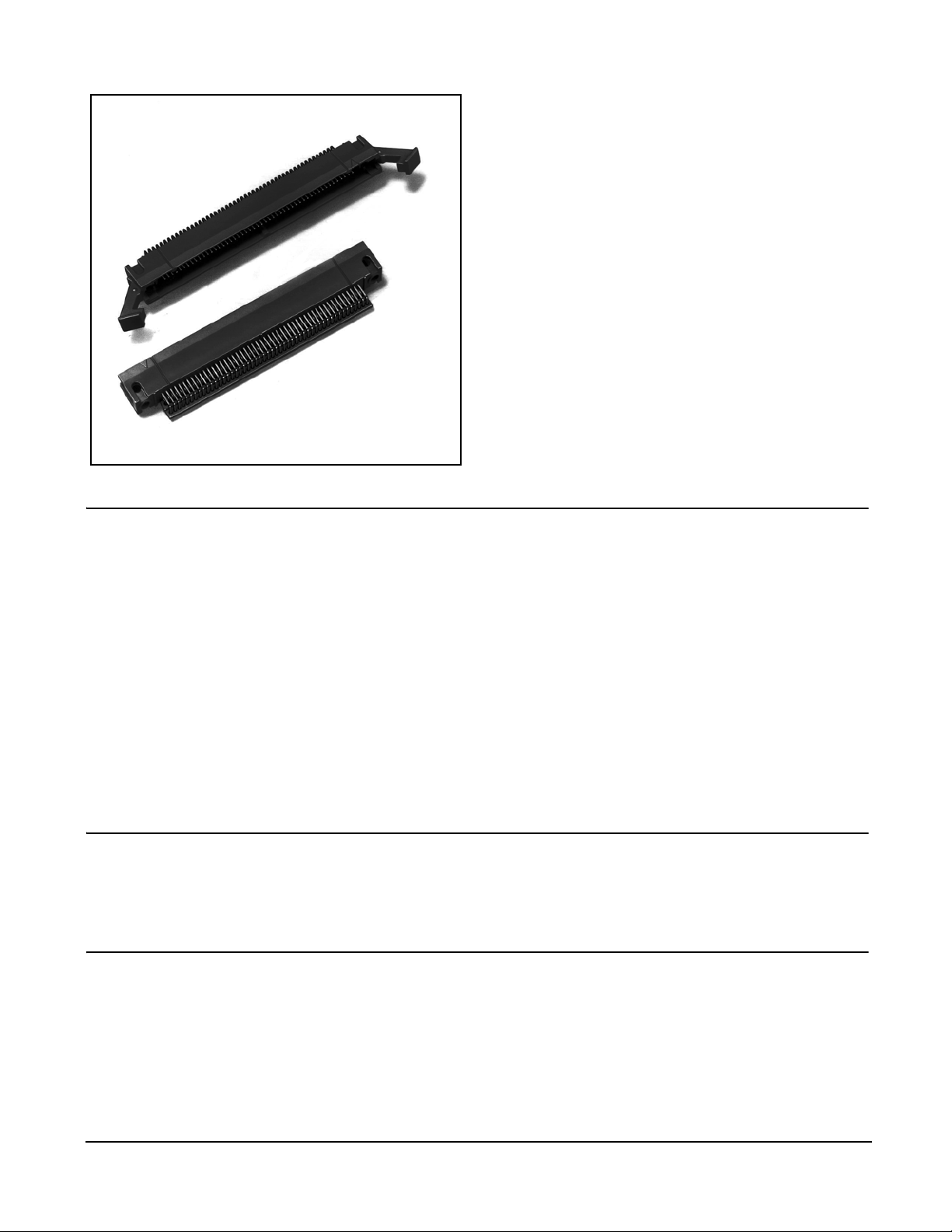
3M™ 4-Wall, Tripolarized Header
.050″ × .100″ Latch/Ejector, PTH & SMT Straight, PTH Right Angle 810 Series
• Tripolarization to mating socket
•50 mil × 100 mil halves the connector length
• Latch and eject for rugged high performance
applications
• Available for thru hole or surface mount
attachment
• High temperature plastic
• Four-wall shroud provides contact protection
• Contacts: 20, 26, 36, 40, 50, 60, 68, 80 and 100
• RoHS* compliant version available (RB plating
suffix)
Physical
Electrical
Insulation
Material:
Flammability:
Color:
Contact
Material:
Plating
Underplating:
Wiping Area:
Solder Tails:
Terminal Finish Indicator:
Marking:
Current Rating:
Insulation Resistance:
Withstanding Voltage:
Date Modified: September 2, 2005
High Temperature Plastic (LCP)
UL 94V-0
Black (RoHS compliant) or Natural
Copper Alloy
100 µ″ [ 2.54 µm ] Nickel
30 µ″ [ 0.76 µm ] Gold
300 µ″ [7.6 µm ] Matte Tin (RoHS compliant) or Tin-Lead (see
ordering information)
e3 (ref JESD97)
3M Logo, Part Number and Orientation Triangle
0.5 A
> 1 × 10⁹ Ω at 500 Vdc
500 Vrms at Sea Level
TS-0253-29
Sheet 1 of 7
Environmental
Temperature Rating:
Process Rating:
Moisture Sensitivity Level:
"RoHS compliant" means that the product or part does not contain any of the following substances in excess of the following maximum concentration values
in any homogeneous material, unless the substance is in an application that is exempt under RoHS: (a) 0.1% (by weight) for lead, mercury, hexavalent
chromium, polybrominated biphenyls or prolybromianted diphenyl ethers; or (b) 0.01% (by weight) for cadmium. Unless otherwise stated by 3M in writing,
UL File No.: E68080
3M
Interconnect Solutions
http://www.3M.com/interconnects/
* RoHS = Directive 2002/95/EC, Restriction of the Use of Certain Hazardous Substances in Electrical and Electronic Equipment
-55°C to +105°C
Maximum
260°C (per J-STD-020C)
1 (per J-STD-020C)
this information represents 3M's knowledge and belief based upon information provided by third party suppliers to 3M.
3M is a trademark of 3M Company.
For technical, sales or ordering information call
800-225-5373
Page 2
3M™ 4-Wall, Tripolarized Header
y
.050″ × .100″ Latch/Ejector, PTH & SMT Straight, PTH Right Angle 810 Series
2X .092
[2.34]
.310
[7.87]
Position 1
.015 X .015
[0.38] X [0.38]
Tolerance Unless Noted
inch ±.1 ±.01 ±.005
[ ] Dimensions for Reference
A
B
C
.015 X .015
[0.38] X [0.38]
See Note 1
Position 2
.050 Typ
[1.27]
Inc h
[m m ]
.0 .00 .000
Onl
.100 Ref
[2.54]
Contact
Qty
020 1.060
026 1.210
036 1.460
040 1.560
050 1.810
060 2.060
068 2.260
080 2.560
100 3.060
[26.92]
[30.73]
[37.08]
[39.62]
[45.97]
[52.32]
[57.40]
[65.02]
[77.72]
PCB Thickness “F” Solder Tail Length ± .010
Table 1
Dimensions
A B C D Short
Ref
.722
[18.34]
.872
[22.15]
1.122
[28.50]
1.222
[31.04]
1.472
[37.39]
1.722
[43.74]
1.922
[48.82]
2.222
[56.44]
2.722
[69.14]
.500
[12.70]
.850
[16.51]
.900
[22.86]
1.000
[25.40]
1.250
[31.75]
1.500
[38.10]
1.700
[43.18]
2.000
[50.80]
2.500
[63.50]
1.671
[42.44]
1.817
[46.15]
2.070
[52.58]
2.170
[55.12]
2.421
[61.49]
2.671
[67.84]
2.870
[72.90]
3.178
[80.72]
3.676
[93.37]
Table 2
.062 [15.7] .090 [2.29]
.094 [2.39] .112 [2.79]
.125 [3.18] .143 [3.63]
D Long
Ref
1.842
[46.77]
1.987
[50.47]
2.274
[57.76]
2.365
[60.07]
2.609
[66.27]
2.872
[72.95]
3.083
[78.31]
3.370
[85.60]
3.875
[98.43]
D
Long Latch
Short Latch
.165 ± .010
[ 4.19 ]
.620 Ref
[ 15.75 ]
Notes:
1. This polarization bump does not exist on the 20 position header.
2. Recommended to be mated to the .050″ X .100″ Wiremount Socket 82XXX Series.
.440 ± .010
[11.18]
Position 1
Orientation Triangle
Ordering Information
81XXX-5X0X03-XX
Contact Quantity
(See Table 1)
Ejector/Latch System:
0 = None
5 = With Short Ejectors Installed
6= With Long Ejector Latches Installed
Contact Tail:
2 = Solder Tail for .062 [ 1.57 ] PC Board
3 = Solder Tail for .094 [ 2.39 ] PC Board
4 = Solder Tail for .125 [ .318 ] PC Board
Plating suffix:
blank = tin lead tails
RB = matte tin tails
(RoHS compliant)
.405
[10.29]
.828 Ref
[ 21.03 ]
.265
[6.73]
.140 ± .010
[3.56]
“F” (See Table 2)
.015
[0.38]
2X Ø.116
[2.95]
Ejector Latch
Long
3505-28 (natural)
3505-28B (black)
Short
3505-29 (natural)
3505-29B (black)
.105
[2.67]
.160 Ref
[4.06]
.306 Ref
[7.77]
TS-0253-29
Sheet 2 of 7
3M
Interconnect Solutions
http://www.3M.com/interconnects/
3M is a trademark of 3M Company.
For technical, sales or ordering information call
800-225-5373
Page 3
3M™ 4-Wall, Tripolarized Header
.050″ × .100″ Latch/Ejector, PTH & SMT Straight, PTH Right Angle 810 Series
Ø.024 ± .003 Typ
[0.64]
.100 ± .002
[2.54]
.025 - .035
[0.64] - [0.89]
*Solder Thief Solder Pads required only on Solder side of PC Board.
.050 ± .002
[1.27]
.045 - .060
[1.14] - [1.52]
*Solder Thief Solder Pads
(See Note 2)
View A
E
.025 ± .002
[0.64]
Table 3
Ejector Latches Dimension E Min
None .575 [14.61]
Long 1.010 [25.65]
Short .885 [22.48]
C ± .002
2X Ø .109 ± .002
[2.77]
.050 ± .002 Typ
[1.27]
Tolerance Noncumulative
Position 2
Flow Solder
Direction
Position 1
Ø.024 ± .003 Typ
[0.64]
Recommended Mounting Hole Pattern
(Shown for mounting side of PC Board)
View A
.100 ± .002
[2.54]
.160 ± .002
[4.06]
.355 Max
[9.02]
.305 Min
[7.75]
Notes:
1. Recommended to process PC Boards through the solder bath such that the connector enters end first (two solder tails at a time).
This will help prevent solder bridging.
2. A Dummy or Solder Thief Solder Pad at the end of each row is recommended on the bottom or solder side of the PC.
Board in order to help prevent solder bridging on the end solder tails. The solder thiefs are only required on the end of the
rows which leave the solder bath last.
3. In order to facilitate flow soldering. It is recommended that ejector latches be installed after the soldering process.
3M
Interconnect Solutions
For technical, sales or ordering information call
3M is a trademark of 3M Company.
http://www.3M.com/interconnects/
TS-0253-29
Sheet 3 of 7
800-225-5373
Page 4

3M™ 4-Wall, Tripolarized Header
.050″ × .100″ Latch/Ejector, PTH & SMT Straight, PTH Right Angle 810 Series
Table 1
Contact
Qty
A B C Short Ref C Long Ref D
020 1.060 [26.92] .722 [18.34] 1.671 [42.44] 1.842 [46.77] .860 [21.84]
026 1.210 [30.73] .872 [22.15] 1.817 [46.15] 1.987 [50.47] 1.010 [25.65]
036 1.460 [37.08] 1.122 [28.50] 2.070 [52.58] 2.274 [57.76] 1.260 [32.00]
040 1.560 [39.62] 1.222 [31.04] 2.170 [55.12] 2.365 [60.07] 1.360 [34.54]
050 1.810 [45.97] 1.472 [37.39] 2.421 [61.49] 2.609 [66.27] 1.610 [40.89]
060 2.060 [52.32] 1.722 [43.74] 2.671 [67.84] 2.872 [72.95] 1.860 [47.24]
068 2.260 [57.40] 1.922 [48.82] 2.870 [72.90] 3.083 [78.31] 2.060 [52.32]
080 2.560 [65.02] 2.222 [56.44] 3.178 [80.72] 3.370 [85.60] 2.360 [59.94]
100 3.060 [77.72] 2.722 [69.14] 3.676 [93.37] 3.875 [98.43] 2.860 [72.64]
.310
[7.87]
Position 2
Dimensions
A
B
See Note 1
Table 2
PCB Thickness "F" Solder Tail Length ± .010
.062 [15.7] .090 [2.29]
.094 [2.39] .112 [2.79]
.125 [3.18] .143 [3.63]
Position 1
.015 X .015
[ 0.38 ] X [ 0.38 ]
Ordering Information
Contact Quantity
(See Table 1)
Ejector/Latch System:
0 = None
5 = With Short Ejectors Installed
6 = With Long Ejector latches Installed
.100 Ref
[2.54]
.050 Typ
[1.27]
Header
81XXX-6X0X0X-XX
Board Mounting Options:
1 = None
3 = Press fit posts both ends
Contact Tail: (See Table 2)
2 = Solder Tail for .062 [ 1.57 ] PC Board
3 = Solder Tail for .094 [ 2.39 ] PC Board
4 = Solder Tail for .125 [ .318 ] PC Board
“F”
(See Table 2)
.100
[2.54]
Notes:
1. This polarization bump does not exist
on the 20 position header.
2. Recommended to be mated to the
.050″ x .100″ 82XXX Series Socket.
Ejector Latch
Long
3505-28 (natural)
3505-28B (black)
Plating suffix:
blank = tin lead tails
RB = matte tin tails
(RoHS compliant)
Short
3505-29 (natural)
3505-29B (black)
.265 [6.73]
.140 ±
.010
TS-0253-29
Sheet 4 of 7
3M
Interconnect Solutions
http://www.3M.com/interconnects/
3M is a trademark of 3M Company.
For technical, sales or ordering information call
800-225-5373
Page 5

3M™ 4-Wall, Tripolarized Header
y
.050″ × .100″ Latch/Ejector, PTH & SMT Straight, PTH Right Angle 810 Series
.100 ± .002
[2.54]
∅.025 ± .003
[0.64]
.025 - .035
[0.64] - [0.89]
*Solder Thief Solder Pads required only on
Solder side of PC Board.
.050 ± .002
[1.27]
.045 - .060
[1.14] - [1.52]
View A
E
2X .205 ± .003
[5.21]
.050 ± .002 Typ
[1.27]
Tolerance Noncumulative
*Solder Thief
Solder Pads
(See Note2)
D ± .002
Flow Solder
Direction
Table 3
Ejector/Latches Dimension E (Min)
None .215 [ 5.46 ]
Long .650 [16.51]
Short .525 [13.34]
.160 Min
[4.06]
.050 ± .003
[1.27]
.100 ± .002
[2.54]
VIEW A
View A
.100 ± .002
2X ∅ .109 ± .002
[2.77]
∅.025 ± .003 Typ
[0.64]
[2.54]
Recommended Mounting Hole Pattern
(Shown for mounting side of PC Board)
Notes:
1. Recommended to process PC Boards through the solder bath such that the connector enters end first (two solder tails at a time).
This will help prevent solder bridging.
.225 Min
[5.72]
Inc h
[mm]
Tolerance Unless Noted
.0 .00 .00 0
inc h ±.1 ±.01 ±.005
[ ] Dim e nsions for R efere nce
Onl
2. A Solder Thief Solder Pad (Dummy Pad) at the end of each row is recommended on the bottom or solder side of the PC
Board in order to help prevent solder bridging on the end solder tails. The Solder Thiefs are only required on the end of the
rows which leave the solder bath last.
3M
Interconnect Solutions
For technical, sales or ordering information call
3M is a trademark of 3M Company.
http://www.3M.com/interconnects/
TS-0253-29
Sheet 5 of 7
800-225-5373
Page 6

3M™ 4-Wall, Tripolarized Header
y
.050″ × .100″ Latch/Ejector, PTH & SMT Straight, PTH Right Angle 810 Series
Table 1
.310
[7.87]
Position 1
.100 Ref
[2.54]
Position 2
See Note 1
[0.38] X [0.38]
.015 X ..015
Contact
Qty
A
020 1.060
B
026 1.210
036 1.460
040 1.560
050 1.810
060 2.060
068 2.260
.050 Typ
[1.27]
080 2.560
100 3.060
A B D Short
[26.92]
[30.73]
[37.08]
[39.62]
[45.97]
[52.32]
[57.40]
[65.02]
[77.72]
[18.34]
[22.15]
[28.50]
[31.04]
[37.39]
[43.74]
[48.82]
[56.44]
[69.14]
.722
.872
1.122
1.222
1.472
1.722
1.922
2.222
2.722
Dimensions
Ref
1.671
[42.44]
1.817
[46.15]
2.070
[52.58]
2.170
[55.12]
2.421
[61.49]
2.671
[67.84]
2.870
[72.90]
3.178
[80.72]
3.676
[93.37]
D Long
Ref
1.842
[46.77]
1.987
[50.47]
2.274
[57.76]
2.365
[60.07]
2.609
[66.27]
2.872
[72.95]
3.083
[78.31]
3.370
[85.60]
3.875
[98.43]
tape &
suffix reel
WD
WE
WF
WG
WH
Short Latch
Position 1
Orientation
Triangle
.620 Ref
[15.75]
.092
[2.34]
Notes:
1. This polarization bump does not exist on the 20 position header.
2. Recommended to be mated to the .050″ X .100″ 82XXX Series Wiremount Socket.
Optional Single Press
Fit Post Mount/Alignment
Feature
∅.116
[2.95]
Ordering Information
D
.165 ± .010
[4.19]
.440 ± .010
[11.18]
Header
Long Latch
Optional Metal
Clip Retention
81XXX-6X0C0X-XX-XX
Contact Quantity
(See Table 1)
Ejector/Latch System:
0 = None
5 = With Short Ejectors Installed
6 = With Long Ejector Latches Installed
Board Mounting Options:
1 = None
4 = Press Fit Post Mount at Position 1 end
7 = Metal retention clips
8 = #1 end press fit post & metal retention clips
.015
[0.38]
.080
[2.03]
Packaging Options:
Blank = Trays
WX = Tape & Reel Package
(see table)
Plating suffix:
blank = tin lead tails
RB = matte tin tails
(RoHS compliant)
.405
[10.29]
.828 Ref
[21.03]
.346 ± .010
[8.79]
.140 ± .010
[3.56]
.265
[6.73]
To lera nce Unless N ote d
[ ] Dimensions for Reference
Inch
[mm]
.0 .00 .0 0 0
inch ±.1 ±.01 ±.005
Onl
Ejector Latch
Long
3505-28 (natural)
3505-28B (black)
Short
3505-29 (natural)
3505-29B (black)
TS-0253-98
Sheet 6 of 7
3M
Interconnect Solutions
http://www.3M.com/interconnects/
3M is a trademark of 3M Company.
For technical, sales or ordering information call
800-225-5373
Page 7

3M™ 4-Wall, Tripolarized Header
.050″ × .100″ Latch/Ejector, PTH & SMT Straight, PTH Right Angle 810 Series
Ejector Latches Dimensions
H Min
No .775 [19.69]
Short 1.085 [27.56]
Long 1.21 [30.73]
No. of Positions Dimensions
F G
∅ .042 ± .003 Typ (Plated thru hole)
[1.07]
Typ, Full R
Detail A
Optional plated thru hole
for metal clip retention
∅.065 ± .002 Typ
[1.65]
20 .450 [11.43] N/A
26 .600 [15.24] N/A
36 .850 [21.59] N/A
40 .950 [24.13] N/A
50 1.200 [30.48] .025 [6.35]
60 1.450 [36.83] 0.000
68 1.650 [41.91] 0.000
80 1.950 [49.53] 0.000
100 2.450 [62.23] 0.000
.158 ± .002
[3.96]
.220 ± .003
[5.59]
Optional Drilled Hole
for Plastic Post
∅.109 ± .002
[2.77]
See Detail A
.110 ± .002
[2.79]
Position 2
.205 ± .003
[5.21]
C
L
F
C
L
.050 ± .002 Typ
[1.27]
Tolerance Noncumulative
.029 ± .001
[0.74]
Position 1
H
.280
[7.11]
C
L
G
C
L
2X .075 ± .002
[1.09]
.376
[9.55]
Recommended Mounting Hole Pattern
(Shown for mounting side of PC Board)
3M
Interconnect Solutions
http://www.3M.com/interconnects/
TS-0253-29
Sheet 7 of 7
3M is a trademark of 3M Company.
For technical, sales or ordering information call
800-225-5373
Page 8

Important Notice
All statements, technical information, and recommendations
related to 3M’s products are based on information believed to be
reliable, but the accuracy or completeness is not guaranteed.
Before using this product, you must evaluate it and determine if it
is suitable for your intended application. You assume all risks and
liability associated with such use. Any statements related to the
product which are not contained in 3M’s current publications, or
any contrary statements contained on your purchase order shall
have no force or effect unless expressly agreed upon, in writing,
by an authorized officer of 3M.
3
Electronics
6801 River Place Blvd.
Austin, TX 78726-9000
800/328-1368
www.3M.com/electronics
Warranty; Limited Remedy; Limited Liability.
This product will be free from defects in material and manufacture
for a period of 90 days from the time of purchase. 3M MAKES
NO OTHER WARRANTIES INCLUDING, BUT NOT LIMITED
TO, ANY IMPLIED WARRANTY OF MERCHANTABILITY OR
FITNESS FOR A PARTICULAR PURPOSE. If this product is
defective within the warranty period stated above, your exclusive
remedy shall be, at 3M’s option, to replace or repair the 3M
product or refund the purchase price of the 3M product.
where prohibited by law, 3M will not be liable for any indirect,
special, incidental or consequential loss or damage arising
from this 3M product, regardless of the legal theory asserted.
Minimum 10%
Post-Consumer Fiber
Printed in USA.
© 3M 2005
Except
 Loading...