

Page 1

3Com® OfficeConnect
Managed PoE Switch
User Guide
3CRDSF9PWR
www.3Com.com
Part Number 10016863 Rev. BA
Published August 2008
Page 2

3Com Corporation
350 Campus Drive
Marlborough,
MA 01752-3064
Copyright © 2008, 3Com Corporation. All rights reserved. No part of this documentation may be reproduced
in any form or by any means or used to make any derivative work (such as translation, transformation, or
adaptation) without written permission from 3Com Corporation.
3Com Corporation reserves the right to revise this documentation and to make changes in content from time
to time without obligation on the part of 3Com Corporation to provide notification of such revision or change.
3Com Corporation provides this documentation without warranty, term, or condition of any kind, either
implied or expressed, including, but not limited to, the implied warranties, terms or conditions of
merchantability, satisfactory quality, and fitness for a particular purpose. 3Com may make improvements or
changes in the product(s) and/or the program(s) described in this documentation at any time.
If there is any software on removable media described in this documentation, it is furnished under a license
agreement included with the product as a separate document, in the hard copy documentation, or on the
removable media in a directory file named LICENSE.TXT or !LICENSE.TXT. If you are unable to locate a copy,
please contact 3Com and a copy will be provided to you.
UNITED STATES GOVERNMENT LEGEND
If you are a United States government agency, then this documentation and the software described herein are
provided to you subject to the following:
All technical data and computer software are commercial in nature and developed solely at private expense.
Software is delivered as “Commercial Computer Software” as defined in DFARS 252.227-7014 (June 1995) or
as a “commercial item” as defined in FAR
provided in 3Com’s standard commercial license for the Software. Technical data is provided with limited rights
only as provided in DFAR 252.227-7015 (Nov
You agree not to remove or deface any portion of any legend provided on any licensed program or
documentation contained in, or delivered to you in conjunction with, this User Guide.
Unless otherwise indicated, 3Com registered trademarks are registered in the United States and may or may not
be registered in other countries.
3Com and the 3Com logo are registered trademarks of 3Com Corporation.
Intel and Pentium are registered trademarks of Intel Corporation. Microsoft, MS-DOS, Windows, and Windows
NT are registered trademarks of Microsoft Corporation. Novell and NetWare are registered trademarks of
Novell, Inc. UNIX is a registered trademark in the United States and other countries, licensed exclusively
through X/Open Company, Ltd.
IEEE and 802 are registered trademarks of the Institute of Electrical and Electronics Engineers, Inc.
All other company and product names may be trademarks of the respective companies with which they are
associated.
2.101(a) and as such is provided with only such rights as are
1995) or FAR 52.227-14 (June 1987), whichever is applicable.
ENVIRONMENTAL STATEMENT
It is the policy of 3Com Corporation to be environmentally friendly in all operations. To uphold our policy, we
are committed to:
Establishing environmental performance standards that comply with national legislation and regulations.
Conserving energy, materials and natural resources in all operations.
Reducing the waste generated by all operations. Ensuring that all waste conforms to recognized environmental
standards. Maximizing the recyclable and reusable content of all products.
Ensuring that all products can be recycled, reused and disposed of safely.
Ensuring that all products are labelled according to recognized environmental standards.
Improving our environmental record on a continual basis.
End of Life Statement
3Com processes allow for the recovery, reclamation and safe disposal of all end-of-life electronic components.
Regulated Materials Statement
3Com products do not contain any hazardous or ozone-depleting material.
Environmental Statement about the Documentation
The documentation for this product is printed on paper that comes from sustainable, managed forests; it is
fully biodegradable and recyclable, and is completely chlorine-free. The varnish is environmentally friendly, and
the inks are vegetable-based with a low heavy-metal content.
Page 3

ABOUT THIS GUIDE
This guide provides information about the Web user interface for the
3Com® OfficeConnect Managed Fast Ethernet PoE Switch. The Web
interface is a network management system that allows you to configure,
monitor, and troubleshoot your switch from a remote web browser. The
Web interface web pages are easy-to-use and easy-to-navigate.
User Guide Overview
This section provides an overview to the User Guide. The User Guide
provides the following sections:
■ Getting Started — Provides introductory information about the
OfficeConnect Managed Fast Ethernet PoE Switch and how it can be
used in your network. It covers summaries of hardware and software
features.
■ Using the 3Com Web Interface — Provides information for using
the Web interface including adding, editing, and deleting device
configuration information.
■ Viewing Basic Settings — provides information for viewing and
configuring essential information required for setting up and
maintaining device settings.
■ Managing Device Security — Provides information for configuring
both system and network security, including traffic control, ACLs, and
device access methods.
■ Managing System Information — Provides information for
configuring general system information including the user-defined
system name, the user-defined system location, and the system
contact person.
■ Configuring Ports — Provides information for configuring port
settings.
Page 4

4 ABOUT THIS GUIDE
■ Aggregating Ports — Provides information for configuring Link
Aggregation which optimizes port usage by linking a group of ports
together to form a single LAG.
■ Configuring VLANs — Provides information for configuring VLANs.
VLANs are logical subgroups with a Local Area Network (LAN) which
combine user stations and network devices into a single virtual LAN
segment, regardless of the physical LAN segment to which they are
attached.
■ Configuring IP and MAC Address Information — Provides
information for configuring IP addresses, DHCP and ARP.
■ Configuring IGMP Snooping — Provides information for
configuring IGMP Snooping and IGMP Query.
■ Configuring Spanning Tree — Provides information for configuring
Classic and Rapid Spanning Tree.
■ Configuring SNMP — Provides information for configuring the
Simple Network Management Protocol (SNMP) which provides a
method for managing network devices.
■ Configuring Quality of Service — Provides information defining
Quality of Service, including default CoS values, queue service mode,
DSCP and CoS mapping, Trust mode, bandwidth settings, and Voice
VLAN.
■ Managing System Files — Provides information for defining file
maintenance.
■ Managing Power over Ethernet Devices — Provides information
for specifying which ports are authorized PoE service, and the service
priority.
■ Managing System Logs — Provides information for viewing system
logs, and configuring device log servers.
■ Viewing Statistics — Provides information for viewing interface and
RMON statistics.
■ Managing Device Diagnostics — Provides information for
managing device diagnostics, including port mirroring, cable testing,
and pinging remote devices.
Page 5
Intended Audience 5
Intended Audience This guide is intended for network administrators familiar with IT
concepts and terminology.
If release notes are shipped with your product and the information there
differs from the information in this guide, follow the instructions in the
release notes.
Most user guides and release notes are available in Adobe Acrobat
Reader Portable Document Format (PDF) or HTML on the 3Com Web site:
■ http://www.3Com.com
Conventions Ta bl e 1 lists conventions that are used throughout this guide.
Ta bl e 1 Notice Icons
Icon Notice Type Description
Information
note
Information that describes important features or
instructions.
Related Documentation
Caution Information that alerts you to potential loss of data
Warning
or potential damage to an application, system, or
device.
Information that alerts you to potential personal
injury.
In addition to this guide, other documentation available for the 3Com®
OfficeConnect Managed Fast Ethernet PoE Switch include the following:
■ Safety and Regulatory Information: Provides installation, set-up, and
regulatory compliance information.
Page 6

6 ABOUT THIS GUIDE
Page 7

CONTENTS
ABOUT THIS GUIDE
User Guide Overview ..................................................................................3
Intended Audience .....................................................................................5
Conventions ...............................................................................................5
Related Documentation ..............................................................................5
1 GETTING STARTED
About the OfficeConnect Managed Fast Ethernet PoE Switch...................16
Summary of Hardware Features ...................................................... 16
Front Panel Detail .....................................................................................17
LED Status Indicators ................................................................................18
System Specifications ...............................................................................19
Approved SFP Transceivers .............................................................. 19
Installing the Switch .................................................................................20
Setting Up for Management.....................................................................21
Methods of Managing a Switch................................................................21
Web Interface Management ........................................................... 22
Command Line Interface Management .......................................... 22
SNMP Management ....................................................................... 23
Switch Setup Overview .............................................................................23
IP Configuration ............................................................................. 25
Using the Command Line Interface (CLI) ...................................................26
Connecting to the Console Port ..................................................... 26
Manually set the IP Address using the Console Port ........................ 27
Viewing IP Information using the Console Port ............................... 28
Setting Up Web Interface Management....................................................30
Web Management Over the Network ............................................. 31
Setting Up Command Line Interface Management ...................................31
CLI Management via the Console Port ............................................ 31
CLI Management over the Network ................................................ 32
Page 8

Setting Up SNMP Management V1 or V2 ................................................. 32
Default Users and Passwords.................................................................... 33
Changing Default Passwords ......................................................... 33
Upgrading Software using the CLI............................................................ 33
2 USING THE 3COM WEB INTERFACE
Starting the 3Com Web Interface............................................................. 36
Multi-Session Web Connections ..................................................... 36
Accessing the 3Com Web Interface ............................................... 37
Understanding the 3Com Web Interface .................................................. 38
Device Representation ................................................................... 40
Using the 3Com Web Interface Management Buttons ................... 40
Using Screen and Table Options ............................................................... 41
Saving the Configuration ......................................................................... 44
Resetting the Device ................................................................................ 45
Restoring Factory Defaults........................................................................ 47
Logging Off the Device ............................................................................ 48
3 VIEWING BASIC SETTINGS
Viewing Device Settings ................................................................. 50
Configuring the Polling Interval ...................................................... 51
Viewing Color Keys ........................................................................ 52
4 MANAGING DEVICE SECURITY
Configuring System Access ...................................................................... 54
Viewing System Access Settings ..................................................... 55
Defining System Access ................................................................. 56
Modifying System Access ............................................................... 57
Removing System Access ............................................................... 58
Defining RADIUS Clients .......................................................................... 59
Defining Port-Based Authentication (802.1X) ........................................... 61
Viewing 802.1X Authentication ..................................................... 62
Defining 802.1X Authentication .................................................... 64
Defining Local Database Authentication................................................... 66
Configuring Local Database Authentication ................................... 67
Viewing Port Settings ..................................................................... 68
Page 9

Configuring Port Settings ............................................................... 69
Viewing User Listing ....................................................................... 70
Creating User Entries ...................................................................... 71
Modifying User Entries ................................................................... 72
Removing User Entries .................................................................... 73
Encrypting Connection to the Web Interface (HTTPS)................................74
Configuring HTTPS ......................................................................... 75
Displaying the Web Server Certificate ............................................. 76
Changing the Digital Certificate ..................................................... 77
Using the Secure Shell Protocol (SSH)........................................................79
Displaying the SSH Key ................................................................... 80
Generating the SSH Key ................................................................. 81
Defining Access Control Lists ....................................................................82
Viewing MAC Based ACLs .............................................................. 83
Configuring MAC Based ACLs ........................................................ 84
Removing MAC Based ACLs ........................................................... 86
Viewing IP Based ACLs ................................................................... 88
Defining IP Based ACLs .................................................................. 90
Removing IP Based ACLs ................................................................ 93
Viewing ACL Binding ..................................................................... 95
Configuring ACL Binding ............................................................... 96
Removing ACL Binding ................................................................... 97
Using Broadcast Storm Control.................................................................98
Displaying Broadcast Storm Control Settings .................................. 99
Configuring Broadcast Storm Control ........................................... 100
5 MANAGING SYSTEM INFORMATION
Viewing System Description....................................................................104
Defining System Settings ........................................................................106
Configuring the System Name ...................................................... 107
Configuring System Time ............................................................. 108
Saving the Device Configuration.............................................................110
Resetting the Device ...............................................................................111
6 CONFIGURING PORTS
Viewing Port Settings ................................................................... 114
Defining Port Settings .................................................................. 116
Page 10

Viewing Port Details ..................................................................... 118
7 AGGREGATING PORTS
Viewing Link Aggregation ............................................................ 122
Configuring Link Aggregation ...................................................... 123
Modifying Link Aggregation ........................................................ 125
Removing Link Aggregation ......................................................... 127
Viewing LACP .............................................................................. 128
Modifying LACP ........................................................................... 129
8 CONFIGURING VLANS
Viewing VLAN Details .................................................................. 132
Viewing VLAN Port Details ........................................................... 133
Creating VLANs ........................................................................... 134
Renaming VLANs ......................................................................... 135
Modifying VLAN Settings ............................................................. 136
Modifying Port VLAN Settings ...................................................... 138
Removing VLANs ......................................................................... 139
9 CONFIGURING IP AND MAC ADDRESS INFORMATION
Defining IP Addressing ........................................................................... 142
Configuring ARP Settings....................................................................... 143
Viewing ARP Settings ................................................................... 144
Defining ARP Settings .................................................................. 145
Removing ARP Entries .................................................................. 146
Viewing Address Tables .......................................................................... 148
Viewing Address Table Settings .................................................... 149
Viewing Port Summary Settings ................................................... 150
10 CONFIGURING IGMP SNOOPING
Defining IGMP Snooping and Query ............................................ 152
11 CONFIGURING SPANNING TREE
Viewing Spanning Tree ................................................................ 156
Defining Global Settings for Spanning Tree .................................. 158
Page 11

Defining Port Settings for Spanning Tree ...................................... 160
12 CONFIGURING SNMP
Setting SNMP Agent Status .......................................................... 164
Defining SNMP Communities and Traps ........................................ 165
Removing SNMP Communities or Traps ........................................ 167
13 CONFIGURING QUALITY OF SERVICE
Viewing CoS Settings ................................................................... 170
Defining CoS ................................................................................ 170
Defining the Queue Mode ............................................................ 172
Viewing CoS to Queue Mapping .................................................. 173
Defining CoS to Queue Mapping ................................................. 174
Viewing DSCP to CoS Mapping ................................................... 175
Configuring DSCP to CoS Mapping .............................................. 176
Configuring Trust Settings ............................................................ 177
Viewing Bandwidth Settings ......................................................... 178
Defining Bandwidth Settings ........................................................ 180
Configuring Voice VLAN.........................................................................182
Viewing Voice VLAN ..................................................................... 183
Defining Voice VLAN .................................................................... 184
Defining Voice VLAN Port Settings ................................................ 186
Viewing Voice VLAN Port Definitions ............................................ 188
Viewing the OUI Summaries ......................................................... 190
Modifying OUI Definitions ............................................................ 191
14 MANAGING SYSTEM FILES
Backing Up System Files ............................................................... 195
Restoring Files .............................................................................. 196
Restoring the Software Image ...................................................... 197
15 MANAGING POWER OVER ETHERNET DEVICES
Viewing PoE Settings .................................................................... 200
Defining PoE Settings ................................................................... 202
Page 12

16 MANAGING SYSTEM LOGS
Viewing Logs ............................................................................... 206
Configuring Logging .................................................................... 207
17 VIEWING STATISTICS
Viewing Port Statistics .................................................................. 210
18 MANAGING DEVICE DIAGNOSTICS
Configuring Port Mirroring..................................................................... 216
Defining Port Mirroring ................................................................ 217
Removing Port Mirroring .............................................................. 219
Configuring Cable Diagnostics ............................................................... 220
Viewing Cable Diagnostics ........................................................... 220
Defining Cable Diagnostics .......................................................... 221
Pinging Another Device.......................................................................... 223
A 3COM NETWORK MANAGEMENT
3Com Network Supervisor ..................................................................... 225
3Com Network Director......................................................................... 226
3Com Network Access Manager............................................................ 226
3Com Enterprise Management Suite...................................................... 227
Integration Kit with HP OpenView Network Node Manager ................... 227
B DEVICE SPECIFICATIONS AND FEATURES
Related Standards .................................................................................. 229
Environmental........................................................................................ 229
Physical.................................................................................................. 229
Electrical ................................................................................................ 230
Switch Features...................................................................................... 230
C PIN-OUTS
Null Modem Cable................................................................................. 235
PC-AT Serial Cable ................................................................................. 235
Modem Cable........................................................................................ 236
Ethernet Port RJ-45 Pin Assignments ...................................................... 236
Page 13

D TROUBLESHOOTING
Problem Management ............................................................................239
Troubleshooting Solutions ......................................................................239
Fail Safe Commands...............................................................................241
E GLOSSARY
..............................................................................................................243
F OBTAINING SUPPORT FOR YOUR 3COM PRODUCTS
Register Your Product to Gain Service Benefits........................................249
TTroubleshoot Online .............................................................................249
Purchase Extended Warranty and Professional Services ...........................250
Access Software Downloads ...................................................................250
Telephone Technical Support and Repair .................................................250
Contact Us .............................................................................................251
REGULATORY NOTICES
Page 14

Page 15

1
GETTING STARTED
This chapter contains introductory information about the 3Com®
OfficeConnect Managed Fast Ethernet PoE Switch and how it can be
used in your network. It covers summaries of hardware and software
features and also the following topics:
■ About the OfficeConnect Managed Fast Ethernet PoE Switch
■ Front Panel Detail
■ LED Status Indicators
■ System Specifications
■ Installing the Switch
■ Setting Up for Management
■ Methods of Managing a Switch
■ Switch Setup Overview
■ Using the Command Line Interface (CLI)
■ Setting Up Web Interface Management
■ Setting Up Command Line Interface Management
■ Setting Up SNMP Management V1 or V2
■ Default Users and Passwords
■ Upgrading Software using the CLI
Page 16

16 CHAPTER 1: GETTING STARTED
About the OfficeConnect Managed Fast Ethernet PoE Switch
The OfficeConnect Managed Fast Ethernet PoE Switch is a switching
product that delivers flexible three-speed performance (10/100/1000),
Power over Ethernet (PoE and PoE Plus) and advanced voice-optimized
features such as auto-QoS and auto-voice VLAN. This makes the switch
ideal for small enterprises seeking to build a secure converged network.
The OfficeConnect Managed Fast Ethernet PoE Switch includes the
following model:
■ OfficeConnect Managed Fast Ethernet PoE Switch (9-Port)
The OfficeConnect Managed Fast Ethernet PoE Switch features the
following advantages:
■ Eight Fast Ethernet access ports
■ One Gigabit Ethernet uplink port
■ Port security
■ Link aggregation control protocol (LACP)
■ Up to 256 VLANs
■ Access control lists (ACLs)
■ Port access control through IEEE 802.1X or local database
■ Port-based mirroring
Summary of
Hardware Features
Ta bl e 1 summarizes the hardware features supported by the
OfficeConnect Managed Fast Ethernet PoE Switch.
Ta bl e 1 Hardware Features
Feature OfficeConnect Managed Fast Ethernet PoE Switch
Addresses Up to 8,000 supported
Auto-negotiation Supported on all ports
Forwarding Modes Store and Forward
Duplex Modes Half and full duplex on all RJ-45 ports
Auto MDI/MDIX Supported on all RJ-45 ports. If fiber SFP transceivers
are used, Auto MDIX is not supported.
Flow Control In full duplex operation all ports are supported.
The Gigabit switch ports are capable of receiving, but
not sending pause frames.
Page 17
Front Panel Detail 17
Table 1 Hardware Features (continued)
Feature OfficeConnect Managed Fast Ethernet PoE Switch
Traffic Prioritization Supported (using the IEEE Std 802.ID, 1998 Edition):
Power over Ethernet and
Power over Ethernet Plus
Fast Ethernet Ports Auto-negotiating 10/100BASE-TX ports
Gigabit Ethernet Ports Auto-negotiating 10/100/1000BASE-T ports
SFP Ethernet Port Supports fiber Gigabit Ethernet long-wave (LX), fiber
Mounting Standalone and rack mounting
Four traffic queues per port
Supported on ports 1-8
Gigabit Ethernet short-wave (SX), and single-strand
fiber Fast Ethernet (BX) transceivers.
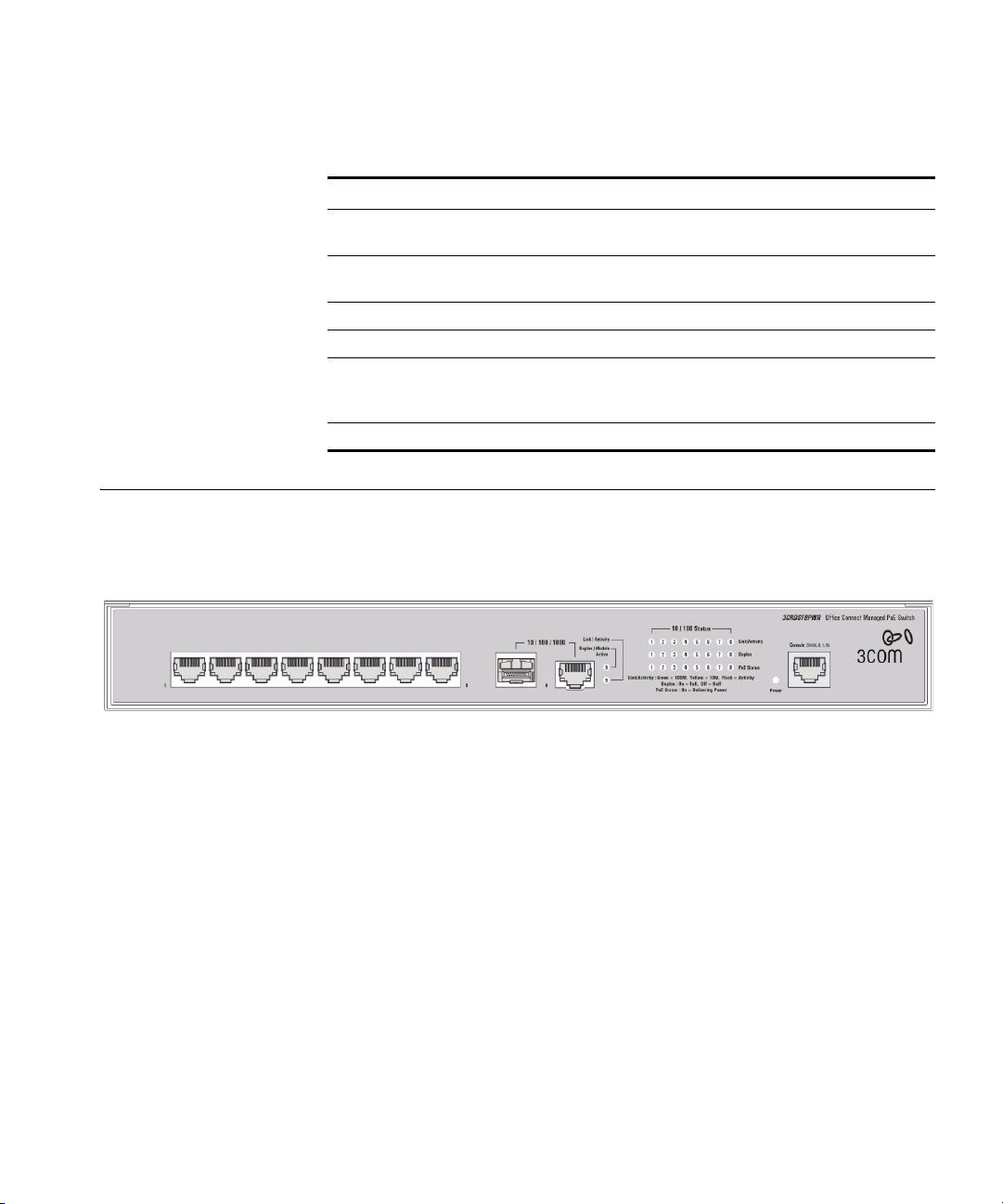
Front Panel Detail Figure 1 shows the front panel of the OfficeConnect Managed Fast
Ethernet PoE Switch 9-Port unit.
Figure 1 OfficeConnect Managed Fast Ethernet PoE Switch—front panel.
Page 18

18 CHAPTER 1: GETTING STARTED
LED Status Indicators
The OfficeConnect Managed Fast Ethernet PoE switch provides LED
indicators on the front panel for your convenience to monitor the switch.
Ta bl e
2 describes the meanings of the LEDs.
Ta bl e 2 Description on the LEDs of the OfficeConnect Managed Fast Ethernet
PoE Switch
LED Label Status Description
Power Power Green The switch starts normally. The LED flashes when
10/100
BASE-TX
Ethernet port
status
10/100/1000
BASE-T
Ethernet port
status
Duplex mode Duplex Yellow The port is in full duplex mode.
100/1000
Base SFP port
status
PoE status PoE
Link/
Activity
Link/
Activity
Module
Active
Status
the system is performing power-on self test (POST)
or firmware is being upgraded.
Yellow The system has failed the POST.
OFF The switch is powered off.
Green The port works at the rate of 100 Mbps; the LED
flashes quickly when the port is sending or receiving
data.
Yellow The port works at the rate of 10 Mbps; the LED
flashes quickly when the port is sending or receiving
data.
OFF The port is not connected.
Green The port works at the rate of 1000 Mbps; the LED
flashes quickly when the port is sending or receiving
data.
Yellow The port works at the rate of 10/100 Mbps; the LED
flashes quickly when the port is sending or receiving
data.
OFF The port is not connected.
OFF The port is not connected, or is in half duplex mode.
Green An SFP module is inserted.
OFF An SFP module is not inserted or is not recognized.
Green Delivering power. The LED flashes if a fault occurs.
OFF Not delivering power.
Page 19

System Specifications 19
System Specifications
Ta bl e 3 contains the system specifications of the OfficeConnect Managed
Fast Ethernet PoE switch.
Ta bl e 3 System specifications of the OfficeConnect Managed Fast Ethernet
switch
PoE
Specification OfficeConnect Managed Fast Ethernet PoE Switch
Physical dimensions
(W×D×H)
Weight 2.04 kg (4.50 lb)
Console port One Console port
Fast Ethernet ports on the
front panel
Gigabit Ethernet ports on
the front panel
SFP ports on the front
panel
AC Input voltage Rated voltage range: 100–240 VAC, 50/60 Hz
Power consumption
(full load)
Operating temperature 0 to 40 °C (32 to 113 °F)
Relative humidity 0 to 95% noncondensing
440×265×43.6 mm (17.3x10.4x1.7 in.)
8 × 10/100 Mbps Ethernet ports
One 10/100/1000 Mbps Ethernet port
(shared with the SFP port)
One 100/1000 Mbps SFP port
(shared with the Gigabit Ethernet RJ-45 port)
200.3 BTU/hr (88 Watts)
Approved SFP
Transceivers
Additional specifications can be found in Appendix B “Device
Specifications and Features”.
The following list of approved SFP transceivers is correct at the time of
publication.
■ 3CSFP91 SFP (1000BASE-SX)
■ 3CSFP92 SFP (1000BASE-LX)
■ 3CSFP85 and 3CSFP86 SFP (100BASE-BX)
To access the latest list of approved SFP transceivers for the switch on the
3Com Corporation World Wide Web site, enter this URL into your
Internet browser:
http://www.3com.com
Page 20
20 CHAPTER 1: GETTING STARTED
Installing the Switch
This section contains information that you need to install and set up your
3Com switch.
WARNING: Safety Information. Before you install or remove any
components from the switch or carry out any maintenance procedures,
you must read the 3Com Switch Family Safety and Regulatory
Information document enclosed.
AVERTISSEMENT: Consignes de securite. Avant d'installer ou d'enlever
tout composant de switch ou d'entamer une procedure de maintenance,
lisez les informations relatives a la securite qui se trouvent dans 3Com
Switch Family Safety and Regulatory Information.
VORSICHT: Sicherheitsinformationen. Bevor Sie Komponenten aus
dem switch entfernen oder den switch hinzufugen oder
Instandhaltungsarbeiten verrichten, lesen Sie die 3Com Switch Family
Safety and Regulatory Information.
ADVERTENCIA: Informacion de seguridad. Antes de instalar o extraer
cualquier componente del switch o de realizar tareas de mantenimiento,
debe leer la informacion de seguridad facilitada en el 3Com Switch Family
Safety and Regulatory Information.
AVVERTENZA: Informazioni di sicurezza. Prima di installare o
rimuovere qualsiasi componente dal switch o di eseguire qualsiasi
procedura di manutenzione, leggere le informazioni di sicurezza riportate
3Com Switch Family Safety and Regulatory Information.
OSTRZEŻENIE: Informacje o zabezpieczeniach. Przed instalacją
lub usunięciem jakichkolwiek elementów z product lub
przeprowadzeniem prac konserwacyjnych należy zapoznać się z
informacjami o bezpieczeństwie zawartymi w 3Com Switch Family
Safety and Regulatory Information.
CAUTION Opening the switch or tampering with the warranty sticker
can void your warranty.
Page 21

Setting Up for Management 21
Setting Up for Management
To make full use of the features offered by your switch, and to change
and monitor the way it works, you have to access the management
software that resides on the switch. This is known as managing the
switch. Managing the switch can help you to improve the efficiency of
the switch and therefore the overall performance of your network.
This section explains the initial set up of the switch and the different
methods of accessing the management software to manage a switch. It
covers the following topics:
■ Methods of Managing a Switch
■ Switch Setup Overview
■ Using the Command Line Interface (CLI)
■ Manually set the IP Address using the Console Port
■ Viewing IP Information using the Console Port
■ Setting Up Web Interface Management
■ Setting Up Command Line Interface Management
■ Setting Up SNMP Management V1 or V2
■ Default Users and Passwords
Methods of Managing a Switch
To manage your switch you can use one of the following methods:
■ Web Interface Management
■ Command Line Interface Management
■ SNMP Management
You can use the Command Line Interface through the Console port for
complete access to all operations of the switch including setting and
viewing the IP address, configuring user accounts, upgrading switch
firmware, and more. Refer to the 3Com CLI Reference Guide.
Page 22
22 CHAPTER 1: GETTING STARTED
Web Interface
Management
Command Line
Interface
Management
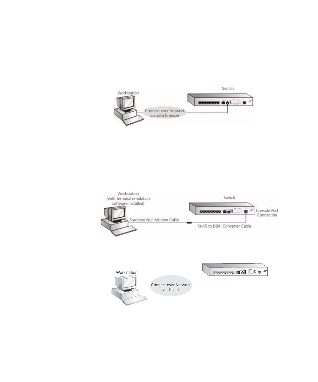
Each switch has an internal set of web pages that allow you to manage
the switch using a Web browser remotely over an IP network (see
Figure 2).
Figure 2 Web Interface Management over the Network
Refer to “Setting Up Web Interface Management” on page 30.
Each switch has a command line interface (CLI) that allows you to
manage the switch from a workstation, either locally via a console port
connection (see
Figure 3 CLI management via the console port
Figure 3), or remotely over the network (see Figure 4).
Figure 4 CLI management over the network
Switch
Refer to “Setting Up Command Line Interface Management” on
page 31.
Page 23
Switch Setup Overview 23
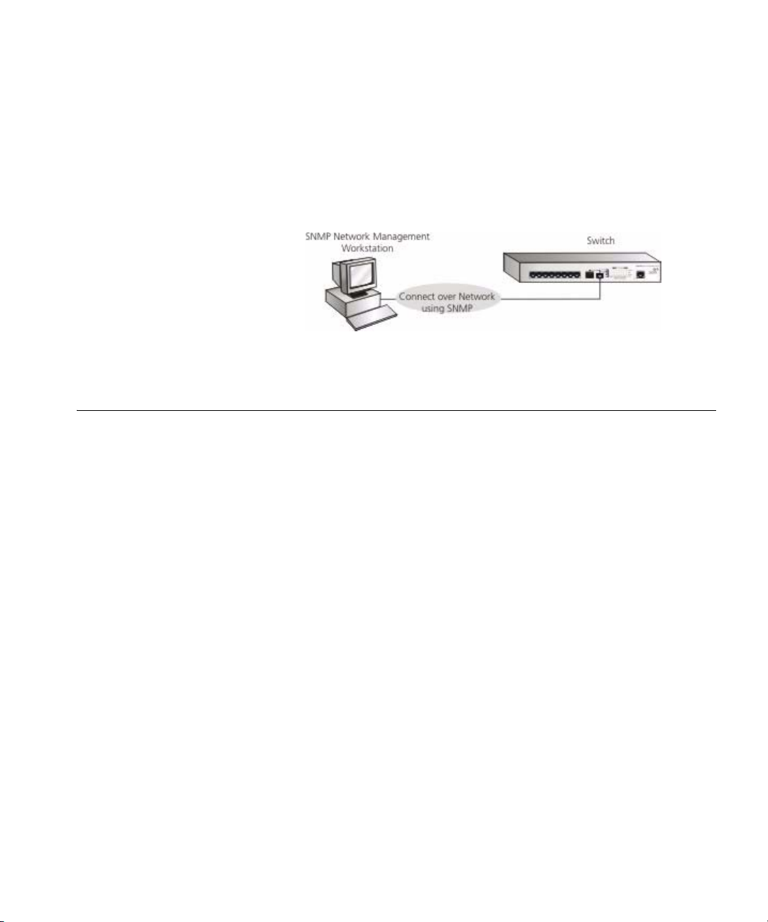
SNMP Management You can manage a switch using any network management workstation
running the Simple Network Management Protocol (SNMP) as shown in
Figure 5. For example, you can use the 3Com Network Director software,
available from the 3Com web site.
Figure 5 SNMP Management over the Network
Refer to “Setting Up SNMP Management V1 or V2” on page 32.
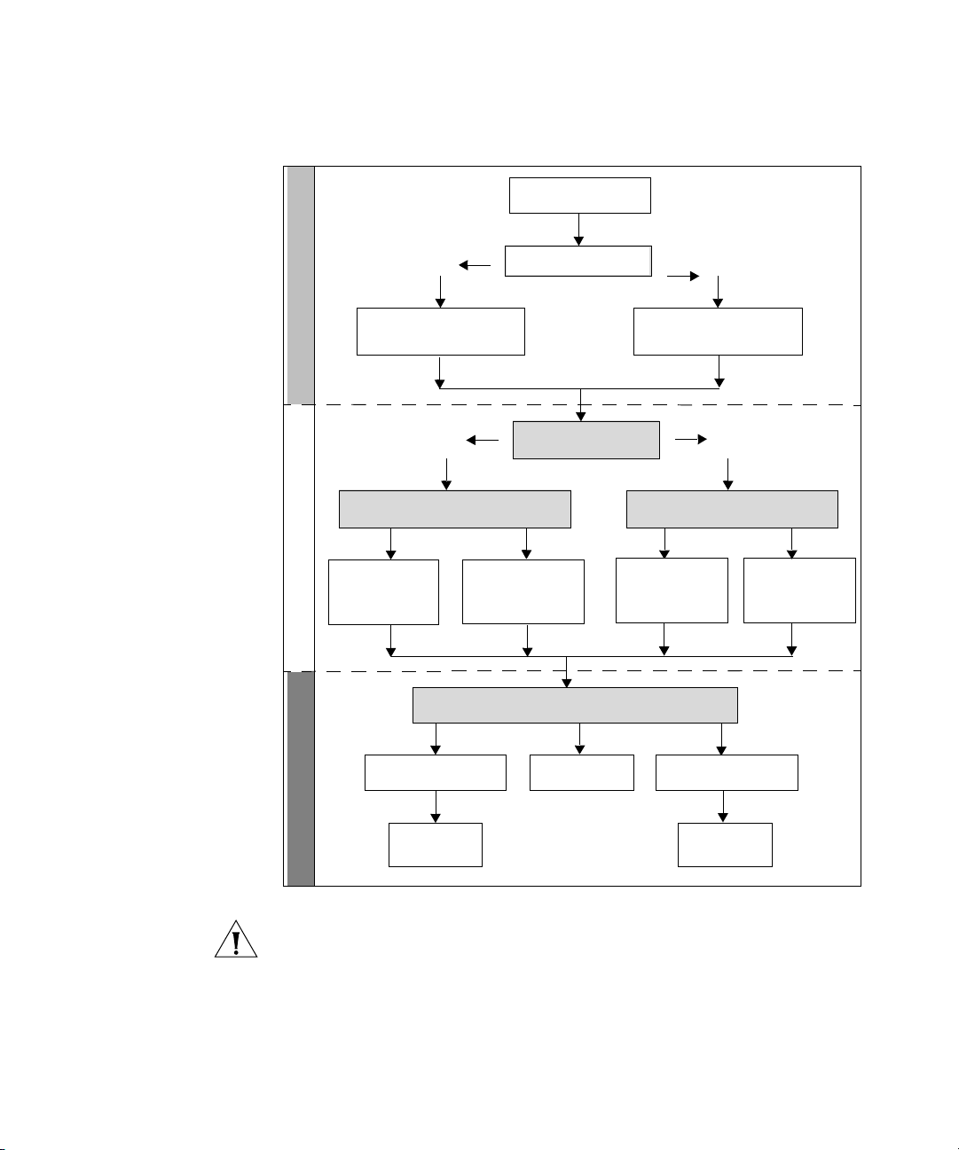
Switch Setup Overview
This section gives an overview of what you need to do to get your switch
set up and ready for management when it is in its default state. The
whole setup process is summarized in
Figure 6. Detailed procedural steps
are contained in the sections that follow. In brief, you need to:
■ Configure IP information manually for your switch or view the
automatically configured IP information
■ Prepare for your chosen method of management
Page 24
24 CHAPTER 1: GETTING STARTED
Figure 6 Initial Switch Setup and Management Flow Diagram
Power Up the Switch.
Plug and Play Setup
Connect to the
console port and use
the Command Line
Initial IP Information Setup
Yes
IP Information is autom atically
configured using D HCP
See page 25
Yes
How do you want to con nect to the switch?
Connect to a front panel
port and use the Web
Interface.
See page 26
Command Line Interfa ce
Interface.
See page 30
How do you want to ma nage your switch? See pa ge 21
Is a DHCP server present?
Do you want to manually
configure the IP inform ation?
Refer to the label on
the rear of the switch
which details the
default IP address.
SNMP
See page 32
No
The switch uses its default IP
information
See page 25
No
How do you want to view the automatically
configured IP inform ation?
Connect to the
console port and use
the Command Line
Interface.
See page 28
Web Interface
Feature Management
Connect using the
console port.
See page 26
Connect over the
network.
See page 31
CAUTION To protect your switch from unauthorized access, you must
change the default password as soon as possible, even if you do not
intend to actively manage your switch. For more information on default
users and changing default passwords, see
“Default Users and
Passwords” on page 33.
Page 25

Switch Setup Overview 25
IP Configuration The switch’s IP configuration is determined automatically using DHCP, or
manually using values you assign.
Automatic IP Configuration using DHCP
By default the switch tries to configure its IP Information without
requesting user intervention. It tries to obtain an IP address from a DHCP
server on the network.
Default IP Address If no DHCP server is detected, the switch will use
its default IP information. The default IP address is 169.254.x.y, where x
and y are the last two bytes of its MAC address.
Note: The switch’s default IP address is listed on a label located on the
bottom and top of the switch.
If you use automatic IP configuration it is important that the IP address of
the switch is static, otherwise the DHCP server can change the switch’s IP
addresses and it will be difficult to manage. Most DHCP servers allow
static IP addresses to be configured so that you know what IP address will
be allocated to the switch. Refer to the documentation that accompanies
your DHCP server.
You should use the Automatic IP configuration method if:
■ your network uses DHCP to allocate IP information, or
■ flexibility is needed. If the switch is deployed onto a different subnet, it
will automatically reconfigure itself with an appropriate IP address,
instead of you having to manually reconfigure the switch.
If you use the automatic IP configuration method, you need to discover
the automatically allocated IP information before you can begin
management. Work through the
“Viewing IP Information using the
Console Port” on page 28.
Manual IP Configuration
When you configure the IP information manually, the switch remembers
the information that you enter until you change it again.
You should use the Manual IP configuration method if:
■ You do not have a DHCP server on your network, or
■ You want to remove the risk of the IP address ever changing, or
Page 26

26 CHAPTER 1: GETTING STARTED
■ Your DHCP server does not allow you to allocate static IP addresses.
For most installations, 3Com recommends that you configure the switch
IP information manually. This makes management simpler and more
reliable as it is not dependent on a DHCP server, and eliminates the risk of
the IP address changing.
To manually enter IP information for your switch, work through the
“Manually set the IP Address using the Console Port” on page 27.
(Static IP addresses are necessary to ensure that the switch is always
allocated the same IP information.)
Using the Command Line Interface (CLI)
Connecting to the
Console Port
You can access the switch through the Console port to manually set the
IP address, or to view the IP address that was assigned automatically (for
example, by a DHCP server).
For more information about the CLI, refer to the 3Com CLI Reference
Guide.
This section describes how to connect to your switch through the
Console port.
Prerequisites
■ A workstation with terminal emulation software installed, such as
Microsoft Hyperterminal. This software allows you to communicate
with the switch using the console port directly.
■ Documentation supplied with the terminal emulation software.
■ The console cable (RJ-45 to DB-9) supplied with your switch.
You can find pin-out diagrams for the cable in Appendix C on page 235.
Page 27
Using the Command Line Interface (CLI) 27
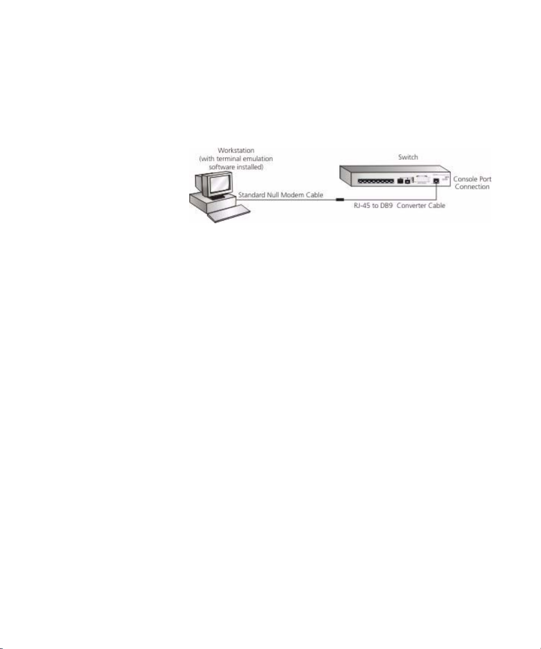
Connecting the Workstation to the Switch
1 Connect the workstation to the console port using the console cable as
shown in
Figure 7 Connecting a Workstation to the switch using the Console Port
Figure 7.
To connect the cable:
a Attach the cable’s RJ-45 connector to the Console port of the switch.
b Attach the other end of the cable to the workstation.
2 Open your terminal emulation software and configure the COM port
settings to which you have connected the cable. The settings must be set
to match the default settings for the switch, which are:
■ 38,400 baud (bits per second)
Manually set the IP
Address using the
Console Port
■ 8 data bits
■ no parity
■ 1 stop bit
■ no hardware flow control
Refer to the documentation that accompanies the terminal emulation
software for more information.
3 Power up the switch. The Power on Self Test (POST) will be performed.
The OfficeConnect Managed Fast Ethernet PoE Switch takes
approximately two minutes to boot.
You are now ready to manually set up the switch with IP information
using the command line interface.
■ You need to have the following information:
■ IP address
■ subnet mask
■ default gateway
Page 28

28 CHAPTER 1: GETTING STARTED
1 Connect to the switch Console port as described in “Connecting to the
Console Port” page 26.
2 The command line interface login sequence begins as soon as the switch
detects a connection to its console port. When the process completes,
the Login prompt displays.
3 At the login prompt, enter admin as your user name and press Return.
The Password prompt displays.
4 Press Return. If you have logged on correctly, the Console# prompt
should be displayed.
5 Enter the following commands to enter configuration mode, specify the
VLAN to which the IP address will be assigned, and then enter the IP
address and subnet mask for the switch as follows:
Console#configure
Console(config)#interface vlan 1
Console(config-if)#ip address xxx.xxx.xxx.xxx
(Note: xxx.xxx.xxx.xxx is the IP address and mmm.mmm.mmm.mmm is
the subnet mask of the switch.)
mmm.mmm.mmm.mmm
Viewing IP
Information using
Console
6 Enter the end command to return to the Privileged Exec mode, and then
enter the quit command to terminate the CLI session.
The initial setup of your switch is now complete and the switch is ready
for you to set up your chosen management method. See
“Methods of
Managing a Switch” on page 21.
This section describes how to view the automatically allocated IP
the
Port
information using the command line interface. The automatic IP
configuration process usually completes within one minute after the
switch is connected to the network and powered up.
1 Connect to the switch Console port as described in “Connecting to the
Console Port” page 26.
The automatic IP configuration process usually completes within one
minute.
2 The command line interface login sequence begins as soon as the switch
detects a connection to its console port.
3 At the login prompt, enter admin as your user name and press Return.
Page 29

Using the Command Line Interface (CLI) 29
4 At the password prompt, press Return.If you have logged on correctly,
the Console# prompt is displayed.
5 Enter show ip interface to view a summary of the allocated IP address.
The following is an example of the displayed information.
Console#show ip interface
IP Address and Netmask: 169.254.99.51 255.255.0.0 on VLAN 1,
Address Mode: DHCP
Console#
The initial set up of your switch is now complete and the switch is ready
for you to set up your chosen management method. See
“Methods of
Managing a Switch” on page 21.
For more information about the CLI, refer to the 3Com CLI Reference
Guide.
If you do not intend to use the command line interface using the console
port to manage the switch, you can log out, disconnect the serial cable
and close the terminal emulator software.
Page 30

30 CHAPTER 1: GETTING STARTED
Setting Up Web Interface Management
This section describes how you can set up web interface management
over the network.
Prerequisites
■ Ensure you have already set up the switch with IP information as
described in
■ Ensure that the switch is connected to the network using a Category 5
“Methods of Managing a Switch” on page 21.
twisted pair Ethernet cable with RJ-45 connectors.
■ A suitable Web browser.
Choosing a Browser
To display the web interface correctly, use one of the following Web
browser and platform combinations:
Ta bl e 4 Supported Web Browsers and Platforms
Platform
Browser
Internet Explorer 5.5 and above Yes Yes Yes
Firefox 6 and above Yes Yes Yes
Netscape 6.2 and above Yes Yes Yes
Windows 2000 Windows XP Windows Vista
For the browser to operate the web interface correctly, JavaScript and
Cascading Style Sheets must be enabled on your browser. These features
are enabled on a browser by default. You will only need to enable them if
you have changed your browser settings.
The switch’s Web interface supports both secure (HTTPS) and non-secure
(HTTP) connections.
Page 31

Setting Up Command Line Interface Management 31
Web Management
Over the Network
To manage a switch using the web interface over an IP network:
1 Be sure that you know your switch’s IP address. See “IP Configuration”
on page 25, and “Viewing IP Information using the Console Port” on
page 28.
2 Check that your management workstation is on the same subnet as your
switch.
3 Check that you can communicate with the switch by entering a ping
command at the DOS or CMD prompt in the following format:
c:\ ping xxx.xxx.xxx.xxx
(where xxx.xxx.xxx.xxx is the IP address of the switch)
If you get an error message, check that your IP information has been
entered correctly and the switch is powered up.
4 Open your web browser and enter the IP address of the switch that you
wish to manage in the URL locator, for example, in the following format:
http://xxx.xxx.xxx.xxx
5 At the login and password prompts, enter admin as your user name and
press Return at the password prompt (or the password of your choice if
you have already modified the default password).
The main Web interface page is displayed.
Setting Up Command Line Interface Management
CLI Management via
the Console Port
This section describes how you can set up command line interface
management using a local console port connection or over the network.
To manage a switch using the command line interface via the local
console port connection:
1 Ensure you have connected your workstation to the console port correctly
as described in
2 Your switch is now ready to continue being managed and/or configured
through the CLI via its console port.
“Connecting to the Console Port” on page 26.
Page 32

32 CHAPTER 1: GETTING STARTED
CLI Management over
the Network
To manage a switch using the command line interface over a network
using Telnet:
1 Ensure you have already set up the switch with IP information as
described in
“Methods of Managing a Switch” on page 21.
2 Check that you have the IP protocol correctly installed on your
management workstation. You can check this by trying to browse the
World Wide Web. If you can browse, the IP protocol is installed.
3 Check that you can communicate with the switch by entering a ping
command at the DOS prompt in the following format:
ping xxx.xxx.xxx.xxx
(where xxx.xxx.xxx.xxx is the IP address of the switch)
If you get an error message, check that your IP information has been
entered correctly and the switch is powered up.
4 To open a Telnet session via the DOS prompt, enter the IP address of the
switch that you wish to manage in the following format:
telnet xxx.xxx.xxx.xxx
(where xxx.xxx.xxx.xxx is the IP address of the switch)
If opening a Telnet session via third party software you will need to enter
the IP address in the format suitable for that software.
5 At the login and password prompts, enter admin as your user name and
enter your password at the password prompt (or just press Return if you
have not yet set a password).
Setting Up SNMP Management V1 or V2
If the login prompt does not display immediately, press Return a few
times until it starts.
6 If you have logged on correctly, the Console# prompt will be displayed.
You can use any network management application running the Simple
Network Management Protocol (SNMP) to manage the switch. 3Com
offers a range of network management applications to address networks
of all sizes and complexity. See
“3Com Network Management” on
page 225.
Be sure the management workstation is connected to the switch using a
port in VLAN 1 (the Default VLAN). By default, all ports on the switch are
in VLAN 1.
Page 33

Default Users and Passwords 33
To display and configure SNMP management parameters, refer to
“Configuring SNMP” on page 163.
Default Users and Passwords
Changing Default
Passwords
Upgrading Software using the CLI
If you intend to manage the switch or to change the default passwords,
you must log in with a valid user name and password. The switch has two
default user names. The default users are listed in
Ta bl e 5 Default Users
User Name
admin (no password) Management — The user can access and change
monitor monitor Monitor — the user can view all manageable
Default
Password
Access Level
all manageable parameters
parameters, but cannot change any manageable
parameters
Ta bl e 5.
Use the admin default user name (no password) to log in and carry out
initial switch setup.
You can change the default passwords using either:
■ The username command on the CLI, or
■ The Administration > System Access > Modify operation on the web
interface.
This section describes how to upgrade software to your switch from the
Command Line Interface (CLI).
Note: You can also upgrade the software using the switch Web user
interface. See “Restoring the Software Image” page 197. Bootcode can
only be upgraded using the CLI, for which instructions are supplied in the
release notes.
1 To download the runtime application file, enter the following commands:
Console#copy tftp file
TFTP server IP address: aaa.aaa.aaa.aaa
Choose file type:
1. config: 2. opcode: <1-2>: 2
Source file name: rrr
Destination file name: rrr
Page 34

34 CHAPTER 1: GETTING STARTED
where aaa.aaa.aaa.aaa is the IP address of the TFTP server, and rrr is the
source runtime filename.
2 When downloading a new runtime file, it will automatically overwrite the
previous version. To set the switch to boot from the new runtime file you
have downloaded, enter the reload command as shown below:
Console(config)#end
Console#reload
The following prompt displays:
System will be restarted, continue <y/n>?
3 Enter y and press Return. The system reboots the switch.
Page 35

2
USING THE 3COM WEB INTERFACE
This section provides an introduction to the user interface, and includes
the following topics:
■ Starting the 3Com Web Interface
■ Understanding the 3Com Web Interface
■ Using Screen and Table Options
■ Saving the Configuration
■ Resetting the Device
■ Restoring Factory Defaults
■ Logging Off the Device
Page 36

36 CHAPTER 2: USING THE 3COM WEB INTERFACE
Starting the 3Com Web Interface
Multi-Session Web
Connections
This section includes the following topics:
■ Multi-Session Web Connections
■ Accessing the 3Com Web Interface
The Multi-Session web connections feature enables 10 users to be
created and access the switch concurrently. Access levels provide read or
read/write permissions to users for configuring the switch. Users and
access levels are described in
Configuring System Access. Login
information is always handled in the local database. A unique password is
required of each user. Two access levels exist on the 3Com Web Interface:
■ Management access level — Provides the user with read/write
access. There is always one management level user configured for the
switch. The factory default is be username: admin with no Password.
■ Monitor access level — Provides the user with read-only access.
Page 37

Starting the 3Com Web Interface 37
Accessing the 3Com
Web Interface
This section contains information on starting the 3Com Web interface.
To access the 3Com user interface:
1 Open an Internet browser.
2 Enter the device IP address in the address bar and press Enter. The Enter
Network Password Page opens:
Figure 8 Enter Network Password Page
3 Enter your user name and password. The device default factory settings is
configured with a User Name that is admin and a password that is blank.
Passwords are case sensitive.
Page 38

38 CHAPTER 2: USING THE 3COM WEB INTERFACE
4 Click . The 3Com Web Interface Home Page opens:
Figure 9 3Com Web Interface Home Page
Tree View
Ta b V i e w
Port Indicators
Understanding the 3Com Web Interface
The 3Com Web Interface Home Page contains the following views:
■ Tree View — Provides easy navigation through the configurable
device features. The main branches expand to display the
sub-features.
■ Tab V i e w — Provides the device summary information located at the
top of the home page.
■ Port Indicators — Located under the Device View at the top of the
home page, the port indicators provide a visual representation of the
ports on the front panel.
Page 39

Understanding the 3Com Web Interface 39
Figure 10 Web Interface Components
Tree View
Web Interface
Information
Tab V iew
The following table lists the user interface components:
Table 6: Interface Components
View Description
Tree View Tree View provides easy navigation through the configurable
device features. The main branches expand to display the
sub-features.
Tab V i e w The Tab Area enables navigation through the different device
features. Click the tabs to view all the components under a
specific feature.
Web
Interface
Provides access to online help, and contains information about
the Web Interface.
Information
Page 40

40 CHAPTER 2: USING THE 3COM WEB INTERFACE
This section provides the following additional information:
■ Device Representation — Provides an explanation of the user
interface buttons, including both management buttons and task
icons.
■ Using the 3Com Web Interface Management Buttons — Provides
instructions for adding, modifying, and deleting configuration
parameters.
Device
Representation
Using the
3Com
Web Interface
Management Buttons
The 3Com Web Interface Home Page contains a graphical panel
representation of the device that appears within the Device View Tab.
To access the Device Representation:
1 Click Device Summary > Device View.
Figure 11 Device Representation
2 By moving your mouse over a port, you can view information about the
port type, speed, duplex mode, utilization, and current status.
3 By selecting a specific port with your mouse, you can open the Port
Administration Detail, Setup or Statistics (Summary) menu.
For detailed information on configuring ports, please refer to Configuring
Ports.
Configuration Management buttons and icons provide an easy method
of configuring device information, and include the following:
Table 7: 3Com Web Interface Configuration Buttons
Button Button Name Description
Clear Logs Clears system logs.
Apply Applies configuration
changes to the device.
Remove Deletes configuration
settings.
Page 41

Using Screen and Table Options 41
Table 8: 3Com Web Interface Information Tabs
Tab Tab N ame Description
Logout Logs the user out and
terminates the current
session.
Using Screen and Ta bl e O p ti o n s
3Com contains screens and tables for configuring devices. This section
contains the following topics:
■ Viewing Configuration Information
■ Adding Configuration Information
■ Modifying Configuration Information
■ Removing Configuration Information
Viewing Configuration Information
To view configuration information:
1 Click Port > Administration > Summary. The Port Settings Summary
Page opens:
Figure 12 Port Settings Summary Page
Page 42

42 CHAPTER 2: USING THE 3COM WEB INTERFACE
Adding Configuration Information
User-defined information can be added to specific 3Com Web Interface
pages, by opening the
To configure IP Setup:
1 Click Administration > IP Setup. The IP Setup Page opens:
Figure 13 IP Setup Page
IP Setup Page.
2 Enter requisite information in the text field.
3 Click . The IP information is configured, and the device is
updated.
Page 43

Using Screen and Table Options 43
Modifying Configuration Information
1 Click Administration > System Access > Modify. The System Access
Modify Page opens:
Figure 14 System Access Modify Page
2 Modify the fields.
3 Click . The access fields are modified.
Removing Configuration Information
1 Click Administration > System Access > Remove. The System Access
Remove Page opens:
Figure 15 System Access Remove Page
2 Select the user account to be deleted.
3 Click . The user account is deleted, and the device is updated.
Page 44

44 CHAPTER 2: USING THE 3COM WEB INTERFACE
Saving the Configuration
Configuration changes are saved to the device’s flash memory every time
the OK button is clicked.
The Save Configuration tab also allows the latest
configuration to be saved to the flash memory.
To save the device configuration:
1 Click Save Configuration. The Save Configuration Page opens:
Figure 16 Save Configuration Page
A message appears: Saving configuration manually. Note: The
configuration is saved automatically every time OK button is clicked. The
operation will save your configuration. Do you wish to continue?
2 Click . The configuration is saved.
Page 45

Resetting the Device 45
Resetting the Device
The Reset Page enables resetting the device from a remote location.
To prevent the current configuration from being lost, use the Save
Configuration Page to save all user-defined changes to the flash memory
before resetting the device.
To reset the device:
1 Click Administration > Reset. The Reset Page opens:
Figure 17 Reset Page
2 Click . A confirmation message is displayed.
Page 46

46 CHAPTER 2: USING THE 3COM WEB INTERFACE
3 Click . Another message is displayed indicating that the device will
reboot in 15 seconds.
4 Click again. The device is reset, and a prompt for a user name
and password is displayed.
Figure 18 User Name and Password Page
5 Enter a user name and password to reconnect to the web interface.
Page 47

Restoring Factory Defaults 47
Restoring Factory Defaults
The Restore option appears on the Reset Page. The Restore option
restores device factory defaults.
To restore the device:
1 Click Administration > Reset. The Reset Page opens:
Figure 19 Reset Page
The Reset Page contains the following fields:
■ Initialize, keep IP Setting — Resets the device with the factory
default settings, but maintains the current IP Address.
■ Initialize all information — Resets the device with the factory
default settings, including the IP Address.
2 Click or . The
system is restored to factory defaults.
Page 48

48 CHAPTER 2: USING THE 3COM WEB INTERFACE
Logging Off the Device
To log off the device:
1 Click . The Logout Page opens.
2 The following message appears:
3 Click . The 3Com Web Interface Home Page closes.
Page 49

3
VIEWING BASIC SETTINGS
This section contains information for viewing basic settings. The 3Com
Web Interface Home Page presents a device summary section that
provides the system administrator with the option to view essential
information required for setting up and maintaining device settings.
The Device Summary Section contains the following views:
■ Viewing Device Settings
■ Configuring the Polling Interval
■ Viewing Color Keys
Page 50

50 CHAPTER 3: VIEWING BASIC SETTINGS
Viewing Device
Settings
The Device Summary Page displays parameters for viewing general device
information, including the system name, location, and contact, the
system MAC Address, System Object ID, System Up Time, and MAC
addresses, and both software, boot, and hardware versions.
To view the Device Summary Settings:
1 Click Device Summary. The Device Summary Page opens:
Figure 20 Device Summary Page
The Device Summary Page contains the following fields:
■ Poll Now — Enables polling the ports for port information including
speed, utilization and port status.
■ Product Description — Displays the device name.
■ System Name — Defines the user-defined device name. The field
length is 0-160 characters.
■ System Location — Defines the location where the system is
currently running. The field range is 0-160 characters.
■ System Contact — Defines the name of the contact person. The field
length is 0-160 characters.
■ Serial Number — Displays the device serial number.
■ Product 3C Number — Displays the 3Com device 3C number.
■ MAC Address — Displays the device MAC address.
■ Software Version — Displays the installed software version number.
Page 51

51
■ Unit Up Time — Displays the amount of time since the most recent
device reset. The system time is displayed in the following format:
Days, Hours, Minutes, and Seconds. For example, 41 days, 2 hours, 22
minutes and 15 seconds.
■ Boot Code Version — Displays the current boot version running on
the device.
■ Hardware Version — Displays the current hardware version of the
device.
Configuring the
Polling Interval
The Polling Interval Page displays the interval at which information on the
Web management pages is refreshed.
To configure the polling interval:
1 Click Device Summary > Polling Interval. The Polling Interval Page
opens:
Figure 21 Polling Interval Page
The Polling Interval Page contains the following fields:
■ Polling Interval — Displays the current setting for the polling interval. The
range for this field is 10-180 seconds, and the default is 60 seconds. This
field can also be set to 0 seconds to disable polling.
2 Define the polling interval.
3 Click . The polling interval is set, and the device is updated.
Page 52

52 CHAPTER 3: VIEWING BASIC SETTINGS
Viewing Color Keys The Color Key Page provides information regarding the RJ45 or SFP port
status on the device. The various colors key indicate the port status,
speed and link of a selected port.
To view color keys:
1 Click Device Summary > Color Key. The Color Key Page opens:
Figure 22 Color Key Page
The Color Key Page contains the following fields:
■ RJ45 — Displays the port status of the Registered Jack 45 (RJ45)
connections which are the physical interface used for terminating
twisted pair type cable.
■ SFP — Displays the port status of the Small Form Factor Pluggable
(SFP) optical transmitter modules that combine transmitter and
receiver functions.
The table includes the color and the port status:
■ White — Unconnected. No link detected.
■ Yel low — Lower speed on 10/100/1000M port.
■ Green — Maximum speed 10/100/1000M RJ45 or SFP. Indicates
that a link was detected.
■ Light Blue — SX/LX/BX SFP. Indicates that a link was detected.
■ Light Gray — Port has been set to inactive by User or
Protocol.
■ Dark Blue — Port has been selected by user.
■ Red — Port or Transceiver has failed POST or Transceivers not
recognized.
Page 53

4
MANAGING DEVICE SECURITY
The Management Security section provides information for configuring
system access, defining RADIUS authentication, port-based
authentication, and access control lists.
This section includes the following topics:
■ Configuring System Access
■ Defining RADIUS Clients
■ Defining Port-Based Authentication (802.1X)
■ Defining Local Database Authentication
■ Encrypting Connection to the Web Interface (HTTPS)
■ Using the Secure Shell Protocol (SSH)
■ Defining Access Control Lists
■ Using Broadcast Storm Control
Page 54

54 CHAPTER 4: MANAGING DEVICE SECURITY
Configuring System Access
Network administrators can
users using the System Access Interface.
define users, passwords, and access levels for
The Multi-Session web feature is
enabled on device and allows 16 users to be created and access the
switch concurrently. Access levels provide read or read/write permissions
to users for configuring the switch. Login information is managed in the
local database. A unique password is required of each user. Two access
levels exist on the 3Com Web Interface:
■ Management access level — Provides the user with read/write
access. There is always one management level user configured for the
switch. The factory default user name is: admin with no password.
■ Monitor access level — Provides the user with read-only system
access.
This section contains the following topics:
■ Viewing System Access Settings
■ Defining System Access
■ Modifying System Access
■ Removing System Access
Page 55

Configuring System Access 55
Viewing System
Access Settings
The System Access Summary Page displays
the current users and access
levels defined on the device.
To view System Access settings:
1 Click Administration > System Access > Summary. The System Access
Summary Page opens:
Figure 23 System Access Summary Page
The System Access Summary Page contains the following fields:
■ User Name — Displays the user names. The possible predefined field
values are:
■ admin — Displays the predefined administrative user name.
■ monitor — Displays the predefined monitor user name.
■ Access Level — Displays the user access level. The lowest user access
level is Monitor and the highest is Management.
■ Management — Provides the user with read and write access
rights.
■ Monitor — Provides the user with read access rights.
Page 56

56 CHAPTER 4: MANAGING DEVICE SECURITY
Defining System
Access
The System Access Setup Page allows network administrators to
define
users, passwords, and access levels for users using the System Access
Interface.
Monitor users have no access to this page.
To define System Access:
1 Click Administration > System Access > Setup. The System Access
Setup Page opens:
Figure 24 System Access Setup Page
The System Access Setup Page contains the following fields:
■ User Name — Defines the user name.
■ Access Level — Defines the user access level. The lowest user access
level is Monitor and the highest is Management.
■ Management — Provides users with read and write access rights.
■ Monitor — Provides users with read access rights.
■ Password — Defines the user password. User passwords can contain
up to 10 characters.
■ Confirm Password — Verifies the password.
2 Define the fields.
3 Click . The user is created, and the device is updated.
Page 57

Configuring System Access 57
Modifying System
Access
The System Access Modify Page allows network administrators to
modify
users, passwords, and access levels for users using the System Access
Interface.
Monitor users have no access to this page.
To modify System Access:
1 Click Administration > System Access > Modify. The System Access
Modify Page opens:
Figure 25 System Access Modify Page
The System Access Modify Page contains the following fields:
■ User Name — Displays the user name.
■ Access Level — Specifies the user access level. The lowest user access
level is Monitoring and the highest is Management.
■ Management — Provides users with read and write access rights.
■ Monitor — Provides users with read access rights.
■ Password Modify — Enables modifying a password for an existing
user.
■ Password — Defines the local user password. Local user passwords
can contain up to 10 characters.
■ Confirm Password — Verifies the password.
2 Select a User Name whose settings are to be modified.
3 Modify the fields.
4 Click . The user settings are modified, and the device is updated.
Page 58

58 CHAPTER 4: MANAGING DEVICE SECURITY
Removing System
Access
The System Access Remove Page allows network administrators to
remove users from the System Access Interface.
Monitor users have no access to this page.
To r e m ov e u s e r s:
1 Click Administration > System Access > Remove. The System Access
Remove Page opens:
Figure 26 System Access Remove Page
The System Access Remove Page contains the following fields:
Remove User(s) — Users to be removed can be selected from the list
below.
■ User Name — Displays the user name.
■ Access Level — Displays the user access level. The lowest user access
level is Monitoring and the highest is Management.
■ Management — Provides users with read and write access rights.
■ Monitoring — Provides users with read access rights.
2 Select the Users to be deleted.
The last user with management access may not be deleted.
3 Click . The Users are deleted, and the device is updated.
Page 59

Defining RADIUS Clients 59
Defining RADIUS Clients
Remote Authorization Dial-In User Service (RADIUS) servers provide
additional security for networks. RADIUS servers provide a centralized
authentication method for 802.1X.
Monitor users have no access to this page.
To configure the RADIUS client:
1 Click Security > RADIUS Client > Configure. The RADIUS Client
Configure Page opens:
Figure 27 RADIUS Client Configure Page
The RADIUS Client Configure Page contains the following fields:
■ Primary Server — Defines the RADIUS Primary Server authentication
fields.
■ Backup Server — Defines the RADIUS Backup Server authentication
fields.
■ IP Address — Defines the RADIUS Server IP address.
■ UDP Port — Defines the authentication port. The authentication port
is used to verify RADIUS server authentication. The authentication port
default is 1812.
■ Max Retries — Defines the number of transmitted requests sent to
the RADIUS server before a failure occurs. Possible field values are
1-30. The default value is 2.
■ Timeout — Defines the amount of time (in seconds) the device waits
for an answer from the RADIUS server before retrying the query, or
Page 60

60 CHAPTER 4: MANAGING DEVICE SECURITY
switching to the next server. Possible field values are 1-65535. The
default value is 5.
■ Key — Defines the default key string used for authenticating and
encrypting all RADIUS-communications between the switch and the
RADIUS server. This key must match the RADIUS encryption. The range
is 0-48 characters. Do not use blank spaces.
■ Verify Key — Verifies the key.
2 Define the fields.
3 Click . The RADIUS client is enabled, and the system is updated.
Page 61

Defining Port-Based Authentication (802.1X) 61
Defining Port-Based Authentication (802.1X)
Port-based authentication authenticates users on a per-port basis via an
external server. Only authenticated and approved system users can
transmit and receive data. Ports are authenticated via the RADIUS server
using the Extensible Authentication Protocol (EAP). Port-based
authentication includes:
■ Authenticators — Specifies the device port which is authenticated
before permitting system access.
■ Supplicants — Specifies the host connected to the authenticated
port requesting to access the system services.
■ Authentication Server — Specifies the server that performs the
authentication on behalf of the authenticator, and indicates whether
the supplicant is authorized to access system services.
Port-based authentication creates two access states:
■ Controlled Access — Permits communication between the
supplicant and the system, if the supplicant is authorized.
■ Uncontrolled Access — Permits uncontrolled communication
regardless of the port state.
This section includes the following topics:
■ Viewing 802.1X Authentication
■ Defining 802.1X Authentication
Page 62

62 CHAPTER 4: MANAGING DEVICE SECURITY
Viewing 802.1X
Authentication
The 802.1X Summary Page allows the network administrator to view
port-based authentication settings.
To view Port-based Authentication:
1 Click Security > 802.1X > Summary. The 802.1X Summary Page opens:
Figure 28 802.1X Summary Page
The 802.1X Summary Page contains the following fields:
■ Port — Displays a list of interfaces.
■ Current Port Control — Displays the current port authorization state.
■ Periodic Reauthentication — Reauthentication can be used to
detect if a new device is plugged into a switch port. If enabled, the
client will be reauthenticated after the interval specified by the
Reauthentication Period.
■ Enabled — Periodic reauthentication is enabled on the port.
■ Disabled — Periodic reauthentication is disabled on the port. This is
the default.
■ Reauthentication Period — Displays the time span (in seconds) in
which the selected port is reauthenticated. The field default is 3600
seconds.
■ Authenticator State — Displays the current authenticator state.
■ Auto — Requires a dot1x-aware connected client to be authorized
by the RADIUS server. Clients that are not dot1x-aware will be
denied access.
Page 63

Defining Port-Based Authentication (802.1X) 63
■ Force-Authorized — Indicates that any client has full access to the
port, even if it does not have 802.1X credentials or support 802.1X
authorization.
■ Force-Unauthorized — Indicates that no client has access to the
port, even if it has 802.1X credentials and supports 802.1X
authorization.
■ Authenticator Operation Mode — Allows single or multiple hosts
(clients) to connect to an 802.1X-authorized port.
■ Multi-Host — Allows multiple hosts to connect to this port.
■ Single-Host — Allows only a single host to connect to this port.
This is the default.
■ Authenticator Maximum Request — Sets the maximum number of
times the switch port will retransmit an EAP request packet to the
client before it times out the authentication session. The field default
is 2.
■ Authenticator Max Count — The maximum number of hosts that
can connect to a port when the Multi-Host operation mode is
selected. The field default is 5.
■ Authenticator Quiet Period — Sets the time that a switch port
waits after the Authenticator Max Count has been exceeded before
attempting to acquire a new client. The field default is 60 seconds.
■ Authenticator Transmit Period — Sets the time period during an
authentication session that the switch waits before re-transmitting an
EAP packet. The field default is 30 seconds.
Page 64

64 CHAPTER 4: MANAGING DEVICE SECURITY
Defining 802.1X
Authentication
The 802.1X Setup Page contains information for configuring 802.1X
global settings on the device and defining specific 802.1X settings for
each port.
Monitor users have no access to this page.
To configure 802.1X Settings:
1 Click Security > 802.1X > Setup. The 802.1X Setup Page opens:
Figure 29 802.1X Setup Page
The 802.1X Setup Page contains the following fields:
802.1X System Setting
■ System Authentication — Specifies if Port Authentication is enabled
on the device. The possible field values are:
■ Enabled — Enables port-based authentication on the device.
■ Disabled — Disables port-based authentication on the device. This
is the default.
Port Settings
■ Operation Mode — Allows single or multiple hosts (clients) to
connect to an 802.1X-authorized port.
■ Multi-Host — Allows multiple hosts to connect to this port.
Page 65

Defining Port-Based Authentication (802.1X) 65
■ Single-Host — Allows only a single host to connect to this port.
This is the default.
■ Admin Port Control — Specifies the admin port authorization state.
■ Auto — Enables port based authentication on the device. The
interface moves between an authorized or unauthorized state
based on the authentication exchange between the device and the
client.
■ Force-Authorized — Places the interface into an authorized state
without being authenticated. The interface re-sends and receives
normal traffic without client port based authentication.
■ Force-Unauthorized — Denies the selected interface system access
by moving the interface into unauthorized state. The device cannot
provide authentication services to the client through the interface.
■ Periodic Reauthentication — Enables periodic reauthentication on
the port.
■ Enabled — Enables periodic reauthentication on the port.
■ Disabled — Disables periodic reauthentication on the port.
■ Maximum Request — Sets the maximum number of times the
switch port will retransmit an EAP request packet to the client before
it times out the authentication session. The field default is 2, the range
is 1-10.
■ Max Count — The maximum number of hosts that can connect to a
port when Multi-Host operation mode is selected. The field default is
5, the range is 1-1024.
■ Reauthentication Period — Defines the time span (in seconds) in
which the selected port is reauthenticated. The field default is 3600
seconds, the range is 1-65535.
■ Quiet Period — Sets the time that a switch port waits after the
Authenticator Max Count has been exceeded before attempting to
acquire a new client. The field default is 60 seconds, the range is
1-65535 seconds.
■ Transmit Period — Sets the time period during an authentication
session that the switch waits before re-transmitting an EAP packet.
The field default is 30 seconds, the range is 1-65535 seconds.
2 Define the fields.
3 Click . The 802.1X Settings are enabled, and the device is updated.
Page 66

66 CHAPTER 4: MANAGING DEVICE SECURITY
Defining
Local
Database
Authentication
Local database authentication allows stations to authenticate and access
the network in situations where 802.1X authentication is infeasible or
impractical. The local database authentication feature allows
unauthenticated hosts to request and receive a DHCP assigned IP address
and perform DNS queries. All other traffic, except for HTTP protocol
traffic, is blocked. The switch intercepts HTTP protocol traffic and
redirects it to a switch-generated web page that facilitates user name and
password authentication. Once authentication is successful, the user is
forwarded on to the originally requested web page.
This section includes the following topics:
■ Configuring Local Database Authentication
■ Viewing Port Settings
■ Configuring Port Settings
■ Viewing User Listing
■ Creating User Entries
■ Modifying User Entries
■ Removing User Entries
Page 67

Defining Local Database Authentication 67
Configuring Local
Database
Authentication
The Local Database Setup Page allows the network administrator to
globally enable or disable local-database authentication for the switch.
Monitor users have no access to this page.
To configure Local Database Settings:
1 Click Port > Local Database > Setup. The Local Database Setup Page
opens:
Figure 30 Local Database Setup Page
The Local Database Setup Page contains the following fields:
■ System Authentication Control — Configures local-database
authentication globally for the switch. The possible field values are:
■ Enabled — Enables local database authentication on the device.
■ Disabled — Disables local database authentication on the device.
This is the default.
2 Define the fields.
3 Click . The Local Database Settings are enabled, and the device is
updated.
Page 68

68 CHAPTER 4: MANAGING DEVICE SECURITY
Viewing Port Settings The Local Database Port Detail Page displays local-database protocol
settings for the selected port.
To display protocol settings for Local Database Authentication:
1 Click Port > Local Database > Port Detail. The Local Database Port
Detail Page opens:
Figure 31 Local Database Port Detail Page
The Local Database Port Detail Page contains the following fields:
■ Port Status — Displays the administrative status of local-database
authentication for a port. The possible field values are:
■ Enabled — Enables local database authentication on the device.
■ Disabled — Disables local database authentication on the device.
■ Quiet Period — Displays the amount of time a host must wait after
exceeding the limit for failed login attempts, before it may attempt
local-database authentication again.
■ Login Attempts — Displays the limit on failed web authentication
login attempts. After the limit is reached, the switch refuses further
login attempts until the quiet time expires.
Page 69

Defining Local Database Authentication 69
Configuring Port
Settings
The Local Database Port Setup Page allows the network administrator to
configure local-database protocol settings for the selected port.
Monitor users have no access to this page.
To display protocol settings for Local Database Authentication:
1 Click Port > Local Database > Port Setup. The Local Database Port
Setup Page opens:
Figure 32 Local Database Port Setup Page
The Local Database Port Setup Page contains the following fields:
■ Status — Configures the administrative status of local-database
authentication for a port. The possible field values are:
■ Enabled — Enables local database authentication on the device.
■ Disabled — Disables local database authentication on the device.
This is the default.
■ No Change — Retains the current port status.
■ Quid Period — Displays the amount of time a host must wait after
exceeding the limit for failed login attempts, before it may attempt
local-database authentication again. The field range is 1-600 seconds,
and the default is 60 seconds.
■ Login Attempts — Displays the limit on failed web authentication
login attempts. After the limit is reached, the switch refuses further
login attempts until the quiet time expires. The field range is 1-3
attempts, and the default is 3 attempts.
Page 70

70 CHAPTER 4: MANAGING DEVICE SECURITY
2 Define the fields.
3 Select the ports to which these settings will be applied.
4 Click . The Local Database Settings are enabled, and the device is
updated.
Viewing User Listing The Local Database User Summary Page displays user names stored in the
local database.
To display the users stored in the Local Database:
1 Click Port > Local Database > User Summary. The Local Database User
Summary Page opens:
Figure 33 Local Database User Summary Page
The Local Database User Summary Page contains the following fields:
■ User Name — The name of users stored in the local database.
Page 71

Defining Local Database Authentication 71
Creating User Entries The Local Database User Setup Page allows the network administrator to
configure user name/password entries in the local database.
Monitor users have no access to this page.
To create user entries in the Local Database:
1 Click Port > Local Database > User Setup. The Local Database User
Setup Page opens:
Figure 34 Local Database User Setup Page
The Local Database User Setup Page contains the following fields:
■ Create a User
■ User Name — The name of a user to be authorized restricted
network access through local database authentication. String
length is 6-12 characters (case sensitive), and the maximum
number of users is 250.
■ Password — The authentication password for the corresponding
user. String length is 6-12 characters (case sensitive).
■ Confirm Password — Verifies the password.
■ Summary
■ User Name — Displays the users stored in the local database.
2 Define the fields for a user.
3 Click . The entry is added to the Local Database, and the device is
updated.
Page 72

72 CHAPTER 4: MANAGING DEVICE SECURITY
Modifying User
Entries
The Local Database User Modify Page allows the network administrator
to change the password for users stored in the local database.
Monitor users have no access to this page.
To modify the password for user entries in the Local Database:
1 Click Port > Local Database > Modify. The Local Database User Modify
Page opens:
Figure 35 Local Database User Modify Page
The Local Database User Modify Page contains the following fields:
■ User Name — The name of a user stored in the local database.
■ Password Modify — Mark this box to modify the password for the
selected user.
■ Password — The authentication password for the corresponding
user. String length is 6-12 characters (case sensitive).
■ Confirm Password — Verifies the password.
2 Select a user from the User Summary list.
3 Mark the Password Modify box.
4 Enter a new password and then confirm it.
5 Click . The user entry is updated in the Local Database, and the
device is updated.
Page 73

Defining Local Database Authentication 73
Removing User
Entries
The Local Database User Remove Page allows the network administrator
to remove user entries stored in the local database.
Monitor users have no access to this page.
To remove a user entry from the Local Database:
1 Click Port > Local Database > Remove. The Local Database User
Remove Page opens:
Figure 36 Local Database User Remove Page
The Local Database User Remove Page contains the following fields:
■ User Name — The name of a user stored in the local database.
2 Select a user from the list.
3 Click . The user entry is removed from the Local Database, and
the device is updated.
Page 74

74 CHAPTER 4: MANAGING DEVICE SECURITY
Encrypting Connection to the Web Interface (HTTPS)
HTTPS allows secure access to the Web interface of the switch. If you
administer your switch remotely or over an insecure network, the switch
can encrypt all HTTP traffic to and from the Web interface using the
Secure Sockets Layer (SSL) of HTTP. If your network traffic is intercepted,
no passwords or configuration information will be visible in the data.
To use HTTPS you need the following:
■ A browser that supports SSL
■ A digital certificate installed on the switch
The switch ships with a default certificate installed. This certificate has not
been validated by a Certifying Authority and your browser may warn you
that the certificate has not been certified. Using a properly validated
certificate provides a higher level of security than the default certificate.
You can securely browse your switch by using the HTTPS (HTTP over SSL)
protocol. To access the Web interface securely, enter the following into
your browser:
https://xxx.xxx.xxx.xxx/
where xxx.xxx.xxx.xxx is the IP address of your switch.
Both HTTP and HTTPS service can be enabled independently on the
switch. However, you cannot configure the HTTP and HTTPS servers to
use the same TCP port.
If you enable HTTPS, you must indicate this in the URL that you specify in
your browser and specify the port number if not using the default value:
https://device[:port_number]
When you start HTTPS, the connection is established in this way:
■ The client authenticates the server using the server’s digital certificate.
■ The client and server negotiate a set of security protocols to use for
the connection.
■ The client and server generate session keys for encrypting and
decrypting data.
Page 75

Encrypting Connection to the Web Interface (HTTPS) 75
The client and server establish a secure encrypted connection.
A padlock icon should appear in the status bar for Internet Explorer 5.x or
above, Netscape 6.2 or above, and Mozilla Firefox 2.0.0.0 or above.
Ta bl e 9 HTTPS System Support
Web Browser Operating System
Internet Explorer
5.0 or later
Netscape
6.2 or later
Mozilla Firefox
2.0.0.0 or later
Windows 98,Windows NT (with service pack 6a), Windows
2000, Windows XP
Windows 98,Windows NT (with service pack 6a), Windows
2000, Windows XP, Solaris 2.6
Windows 2000, Windows XP, Linux
Configuring HTTPS The HTTPS Configure Page allows network administrators to
disable HTTPS and set the TCP port number for this service.
Monitor users have no access to this page.
To configure HTTPS settings:
1 Click Security > HTTPS Settings > Configure. The HTTPS Configure
Page opens:
Figure 37 HTTPS Configure Page
enable or
The HTTPS Configure Page contains the following fields:
■ HTTPS Status — Specifies if HTTPS is enabled on the device. The
possible predefined field values are:
■ Enabled — HTTPS is enabled on the device. This is the default.
Page 76

76 CHAPTER 4: MANAGING DEVICE SECURITY
■ Disabled — HTTPS is disabled on the device.
■ Change HTTPS Port Number — Specifies the TCP port to be used for
HTTPS. The default value is 443, and the range is 1-65535.
You cannot configure the HTTP and HTTPS servers to use the same port.
If you change the HTTPS port number, clients attempting to connect to
the HTTPS server must specify the port number in the URL in this format:
https://device:port_number
2 Define the fields.
3 Click . The HTTPS settings are updated.
Displaying the Web
Server Certificate
The HTTPS Detail Page allows users to
display detailed information about
the web server certificate.
To view information about the digital certificate:
1 Click Security > HTTPS Settings > Detail. The HTTPS Detail Page opens:
Figure 38 HTTPS Detail Page
The HTTPS Detail Page contains the following fields:
■ Issued to — Shows the registered user of this certificate.
■ Issued by — Shows the certification authority that issued this
certificate.
■ Valid from/until — Shows the validity period for this certificate.
■ SHA1 Fingerprint — Hash sting used to encrypt communications.
■ MD5 Fingerprint — Hash sting used to encrypt communications.
Page 77

Encrypting Connection to the Web Interface (HTTPS) 77
Changing the Digital
Certificate
The switch ships with a default certificate. However, this certificate has
not been validated by a Certifying Authority. Using a properly validated
certificate provides a higher level of security than the default certificate.
To access your switch using HTTPS, you need a digital certificate which
identifies it. The switch uses certificates that adhere to the X.509
standard.
If you have the software to generate an X.509 certificate, you can
self-certify your switch. Administrators will be warned that the certificate
has not been certified by a Certificate Authority (CA), but security will not
be otherwise affected.
If you cannot generate an X.509 certificate yourself, you can buy one
from one of the Certifying Authorities or your ISP. Each switch requires its
own X.509 certificate.
To download an HTTPS certificate:
1 Click Security > HTTPS Settings > Download Certificate. The HTTPS
Download Certificate Page opens:
Figure 39 HTTPS Download Certificate Page
The HTTPS Download Certificate Page contains the following fields:
■ IP Address — Network address of a TFTP server.
■ Certificate Filename — Filename of the digital certificate.
■ Private Key Filename — Name of file containing the certificate.
Page 78

78 CHAPTER 4: MANAGING DEVICE SECURITY
■ Private Key Password — Password stored in the private key file. This
password is used to verify authorization for certificate use, and is
verified when downloading the certificate to the switch.
2 Define the fields.
3 Click . The certificate is downloaded.
You must reboot the switch to start using the new certificate.
Page 79

Using the Secure Shell Protocol (SSH) 79
Using the Secure Shell Protocol (SSH)
Secure Shell (SSH) provides a secure replacement for management access
via Telnet. When an SSH management client contacts the switch, the
switch first compares the public-key and password provided by the client
against those stored locally before granting access. SSH also encrypts all
data transfers passing between the switch and SSH management clients,
and ensures that data traveling over the network arrives unaltered.
Note that you need to install an SSH client on the management station to
access the switch for management via the SSH protocol.
The switch supports both SSH Version 1.5 and 2.0 clients.
The SSH server on this switch supports local password authentication.
Note that although the switch only supports password authentication,
you still have to generate a public key on the switch.
To use the SSH server, complete these steps:
1 Generate a Host Key Pair – No keys are generated in the switch’s factory
default configuration. You must use the
SSH Key Generate Page to create
a public host key.
2 Provide Host Public Key to Clients – Many SSH client programs
automatically import the host public key during the initial connection
setup with the switch. Otherwise, you need to manually create a known
hosts file on the management station and place the host public key in it.
An entry for a public key in the known hosts file would appear similar to
the following example:
10.1.0.54 1024 35
15684995401867669259333946775054617325313674890836547254150202455
93199868544358361651999923329781766065830956108259132128902337654
68017262725714134287629413011961955667825956641048695742788814620
65194174677298486546861571773939016477935594230357741309802273708
779454524083971752646358058176716709574804776117
Password Authentication (for SSH v1.5 or V2 Clients)
a The client sends its password to the server.
b The switch compares the client's password to those stored in memory.
c If a match is found, the connection is allowed.
Page 80

80 CHAPTER 4: MANAGING DEVICE SECURITY
To use SSH with password authentication, the host public key must still
be given to the client, either during initial connection or manually entered
into the known host file. You do not need to configure the client’s keys.
The SSH server supports up to four client sessions. The maximum number
of client sessions includes both current Telnet sessions and SSH sessions.
Displaying the SSH
Key
The SSH Host Key Page shows the public key used for management
access to the switch through an SSH client application.
To view the DSA and RSA keys:
1 Click Security > SSH > Host Key. The SSH Host Key Page opens:
Figure 40 SSH Host Key Page
The SSH Host Key Page contains the following fields:
■ Key — When an RSA key is displayed, the first field indicates the size
of the host key (e.g., 1024), the second field is the encoded public
exponent (e.g., 65537), and the last string is the encoded modulus.
When a DSA key is displayed, the first field indicates that the
encryption method used by SSH is based on the Digital Signature
Standard (DSS), and the last string is the encoded modulus.
■ Key Type — Indicates DSA or RSA key type, the key size, and the SSH
client versions which may use this key.
■ Fingerprint — Hash algorithms used to generate the key.
Page 81

Using the Secure Shell Protocol (SSH) 81
Generating the SSH
Key
The SSH Key Generate Page generates both the DSA and RSA key pairs.
No keys are generated in the switch’s factory default configuration. You
must use this web page to create a public host key.
Gererating a SSH key can take up to 15 minutes, during which time the
user interface to the switch may not respond.
To generate DSA and RSA keys:
1 Click Security > SSH > Generate. The SSH Key Generate Page opens:
Figure 41 SSH Key Generate Page
The SSH Key Generate Page contains a prompt message to enter a seed
to randomize the key generation process:
2 Enter any random string, preferably eight characters or more.
3 Click . The switch begins generating the public host key. This
process takes several minutes to complete. After the key is generated, it is
stored in flash memory.
The SSH server on the switch uses this host key to negotiate a session key
and encryption method with the client trying to connect to it.
Some SSH client programs automatically add the public key to the known
hosts file as part of the configuration process. Otherwise, you must
manually create a known hosts file and place the host public key in it.
Page 82

82 CHAPTER 4: MANAGING DEVICE SECURITY
Defining Access Control Lists
Access Control Lists (ACLs) allow network managers to define
classification actions and rules for specific ingress ports. Packets entering
an ingress port, with an active ACL are either admitted or denied entry.
For example, an ACL rule states that port number 20 can receive TCP
packets, however, if a UDP packet is received, the packet will be dropped.
ACLs are composed of access control entries (ACEs) that are made of the
filters that determine traffic classifications.
The following are examples of filters that can be defined as ACEs:
■ Source Port IP Address and Wildcard Mask — Filters packets by
the source port IP address and wildcard mask.
■ Destination Port IP Address and Wildcard Mask — Filters packets
by the destination port IP address and wildcard mask.
■ Protocol — Filters packets by the IP protocol.
■ DSCP — Filters packets by the DiffServ Code Point (DSCP) value.
■ IP Precedence — Filters packets by the IP Precedence.
■ Action — Indicates the action assigned to the packet matching the
ACL. Packets are forwarded or dropped.
This section includes the following topics:
■ Viewing MAC Based ACLs
■ Configuring MAC Based ACLs
■ Removing MAC Based ACLs
■ Viewing IP Based ACLs
■ Defining IP Based ACLs
■ Removing IP Based ACLs
■ Viewing ACL Binding
■ Configuring ACL Binding
■ Removing ACL Binding
Page 83

Defining Access Control Lists 83
Viewing MAC Based
ACLs
The MAC Based ACL Summary Page displays information regarding MAC
Based ACLs configured on the device.
To view MAC Based ACLs:
1 Click Device > ACL > MAC Based ACL > Summary. The MAC Based
ACL Summary Page opens:
Figure 42 MAC Based ACL Summary Page
The MAC Based ACL Summary Page contains the following fields:
■ ACL Name — Contains a list of the MAC-based ACLs.
■ Source Address — Indicates the source MAC address.
■ Source Mask — Indicates the source MAC address Mask.
■ Destination Address — Indicates the destination MAC address.
■ Destination Mask — Indicates the destination MAC address Mask.
■ VLAN ID — Matches the packet's VLAN ID to the ACL rule. The
possible field values are 0 to 4095.
■ CoS — Classifies traffic based on the CoS tag value.
■ CoS Mask — Displays the CoS mask used to filter CoS tags.
■ Ethertype — Provides an identifier that differentiates between
various types of protocols.
Page 84

84 CHAPTER 4: MANAGING DEVICE SECURITY
■ Action — Indicates the ACL forwarding action. The options are as
follows:
■ Permit — Forwards packets which meet the ACL criteria.
■ Deny — Drops packets which meet the ACL criteria.
Configuring MAC
Based ACLs
The MAC Based ACL Setup Page allows the network administrator to
create and define rules for MAC-based ACLs.
Monitor users have no access to this page.
To configure MAC-based ACLs:
Click Device > ACL > MAC Based ACL > Setup. The MAC Based ACL
Setup Page opens:
Figure 43 MAC Based ACL Setup Page
The MAC Based ACL Setup Page contains the following fields:
■ Select ACL — Selects an existing MAC-based ACL to which rules are
to be added.
■ Create ACL — Defines a new user-defined MAC-based ACL.
Page 85

Defining Access Control Lists 85
Add Rules to ACL
■ Source MAC Address — Matches the source MAC address to which
packets are addressed.
■ Source Mask — Defines the source MAC Address wildcard mask.
Wildcards are used to mask all or part of a source MAC address.
Wildcard masks specify which bits are used and which are ignored.
A
wildcard mask of FF:FF:FF:FF:FF:FF indicates that all the bits are
important. A wildcard of 00.00.00.00.00.00.00 indicates that no bits
are important. For example, if the source MAC address is
00:AB:22:11:33:00 and the wildcard mask is FF:FF:FF:FF:FF:00, the first
five bytes of the MAC are used, while the last byte is ignored. For the
source MAC address 00:AB:22:11:33:00, this wildcard mask matches
all MAC addresses in the range 00:AB:22:11:33:00 to
00:AB:22:11:33:FF.
■ Destination MAC Address — Matches the destination MAC address
to which packets are addressed.
■ Destination Mask — Defines the destination MAC Address wildcard
mask. Wildcards are used to mask all or part of a destination MAC
address. Wildcard masks specify which bits are used and which are
ignored. For more details, refer to the description for Source Mask.
■ VLAN ID — Matches the packet's VLAN ID. The possible field values
are 0 to 4095.
■ CoS — Classifies traffic based on the CoS tag value. The possible field
values are 0 to 7.
■ CoS Mask — Defines the CoS mask used to classify network traffic.
The possible field values are 0 to 7.
■ Ethertype — Provides an identifier that differentiates between
various types of protocols. The range is 0-65535 decimal.
■ Action — Specifies the ACL forwarding action. The options are as
follows:
■ Permit — Forwards packets which meet the ACL criteria.
■ Deny — Drops packets which meet the ACL criteria.
To create a new MAC-based ACL:
1 Select Create ACL.
2 Enter the name of the new ACL.
3 Click . The new ACL is created, and the device is updated.
Page 86

86 CHAPTER 4: MANAGING DEVICE SECURITY
To define a new MAC-based ACL rule:
1 Select Select ACL.
2 Select the ACL from the list.
3 Define the fields for the new ACL rule.
4 Click . The new MAC-based ACL rule settings are configured,
and the device is updated.
Removing MAC Based
ACLs
The MAC Based ACL Remove Page allows the network administrator to
remove MAC-based ACLs or MAC-based ACL rules.
Monitor users have no access to this page.
Click Device > ACL > MAC Based ACL > Remove. The MAC Based ACL
Remove Page opens:
Figure 44 MAC Based ACL Remove Page
The MAC Based ACL Remove Page contains the following fields:
■ ACL Name — Selects a MAC-based ACL for removal.
■ Remove ACL — Enables the ACL to be removed.
■ Checkbox (unnamed) — When checked, selects the rule for removal.
The top checkbox is used to select all rules for removal.
■ Source Address — Matches the source MAC address to which
packets are addressed.
■ Source Mask — Matches the source MAC address Mask.
Page 87

Defining Access Control Lists 87
■ Destination Address — Matches the destination MAC address to
which packets are addressed.
■ Destination Mask — Matches the destination MAC address Mask.
■ VLAN ID — Matches the packet's VLAN ID to the rule.
■ CoS — Classifies Class of Service of the packet.
■ CoS Mask — Displays the wildcard mask bits to be applied to the
CoS.
■ Ethertype — Provides an identifier that differentiates between
various types of protocols.
■ Action — Indicates the ACL forwarding action. The options are as
follows:
■ Permit — Forwards packets which meet the ACL criteria.
■ Deny — Drops packets which meet the ACL criteria.
To remove MAC-based ACLs:
1 Select the ACL Name to be deleted.
2 Check Remove ACL.
3 Click . The selected ACL is deleted, and the device is updated.
To remove MAC-based ACL rules:
1 Select the ACL Name containing the rules to be deleted.
2 For each rule to be removed, check the box to the left of the row in the
rules table. To remove all rules, the topmost box may be checked.
3 Click . The selected MAC-based ACL rules are deleted, and the
device is updated.
Page 88

88 CHAPTER 4: MANAGING DEVICE SECURITY
Viewing IP Based
ACLs
The IP Based ACL Summary Page displays information regarding IP-based
ACLs configured on the device.
To view IP-based ACLs:
1 Click Device > ACL > IP Based ACL > Summary. The IP Based ACL
Summary Page opens:
Figure 45 IP Based ACL Summary Page
The IP Based ACL Summary Page contains the following fields:
■ ACL Name — Contains a list of the IP Based ACLs.
■ Protocol — Indicates the protocol in the rule to which the packet is
matched.
■ Source Port — Indicates the source port to match in packets. Enabled
only when TCP or UDP are selected in the Protocol list.
■ Destination Port — Indicates the destination port to match in
packets. Enabled only when TCP or UDP are selected in the Protocol
list.
■ Flag Set — Indicates the TCP flag to which the packet is mapped.
■ Source IP Address — Matches the source IP address to which
packets are addressed.
■ Source Mask — Indicates the source IP address mask.
Page 89

Defining Access Control Lists 89
■ Dest. IP Address — Matches the destination IP address to which
packets are addressed.
■ Destination Mask — Indicates the destination IP address mask.
■ Match DSCP — Matches the packet DSCP value.
■ Match IP Precedence — Indicates matching IP Precedence with the
packet IP precedence value.
■ Action — Indicates the ACL forwarding action. The options are as
follows:
■ Permit — Forwards packets which meet the ACL criteria.
■ Deny — Drops packets which meet the ACL criteria.
Page 90

90 CHAPTER 4: MANAGING DEVICE SECURITY
Defining IP Based
ACLs
Access Control Lists (ACL) allow network managers to define
classification actions and rules for specific ingress ports. Your switch
supports up to 256 ACLs. Packets entering an ingress port, with an active
ACL, are either admitted or denied entry. ACLs are composed of access
control entries (ACEs) that are made of the filters that determine traffic
classifications. The total number of ACEs that can be defined in all ACLs
together is 256.
Monitor users have no access to this page.
To configure IP-based ACLs:
Click Device > ACL > IP Based ACL > Setup. The IP Based ACL Setup
Page opens:
Figure 46 IP Based ACL Setup Page
The IP Based ACL Setup Page contains the following fields:
■ Select ACL — Selects an existing IP-based ACL to which rules are to
be added.
■
Create ACL — Defines a new user-defined IP-based ACL.
Page 91

Defining Access Control Lists 91
Add Rules to ACL
■ Protocol — Defines the protocol in the rule to which the packet is
matched. The possible fields are:
■ Select from List — Selects a protocol from a list by which packets
are matched.
■ Protocol ID — Adds user-defined protocols by which packets are
matched. Each protocol has a specific protocol number which is
unique. The possible field range is 0-255.
■ Source Port — Defines the source port that is used for matched
packets. Enabled only when TCP or UDP are selected in the Protocol
list. The field value is either user defined or Any. If Any is selected the
IP based ACL is applied to any source port.
■ Destination Port — Defines the destination port that is used for
matched packets. Enabled only when TCP or UDP are selected in the
Protocol list. The field value is either user defined or Any. If Any is
selected, the IP based ACL is applied to any destination port.
■ TCP Flags — If checked, enables configuration of TCP flags matched
to the packet. The possible fields are:
■ URG — Urgent pointer field significant. The urgent pointer points
to the sequence number of the octet following the urgent data.
■ ACK — Acknowledgement field significant. The acknowledgement
field is the byte number of the next byte that the sender expects to
receive from the receiver.
■ PSH — Push (send) the data as soon as possible, without buffering.
This is used for interactive traffic.
■ RST — Reset the connection. This invalidates the sequence
numbers and aborts the session between the sender and receiver.
■ SYN — Synchronize Initial Sequence Numbers (ISNs). This is used to
initialize a new connection.
■ FIN — Finish. This indicates there is no more data from the sender.
This marks a normal closing of the session between the sender and
receiver.
For each TCP flag, the possible field values are:
■ Set — Enables the TCP flag.
■ Unset — Disables the TCP flag.
■ Don’t Care — Does not check the packet’s TCP flag.
Page 92

92 CHAPTER 4: MANAGING DEVICE SECURITY
■ Source IP Address — If selected, enables matching the source port IP
address to which packets are addressed to the rule, according to a
wildcard mask. The field value is either user defined or Any. If Any is
selected, accepts any source IP address and disables wildcard mask
filtering.
■ Wild Card Mask — Defines the source IP address wildcard mask.
Wildcard masks specify which bits are used and which bits are
ignored. A wildcard mask of 255.255.255.255 indicates that all the
bits are important. A wildcard mask of 0.0.0.0 indicates that no
bits are important. For example, if the source IP address is
149.36.184.198 and the wildcard mask is 255.255.255.0, the first
three bytes of the IP address are matched, while the last eight bits
are ignored. For the source IP address 149.36.184.198, this
wildcard mask matches all IP addresses in the range 149.36.184.0
to 149.36.184.255. A wildcard mask must not contain leading
zeroes. For example, a wildcard mask of 010.010.011.010 is
invalid, but a wildcard mask of 10.10.11.10 is valid.
■ Destination IP Address — If selected, enables matching the
destination port IP address to which packets are addressed to the rule,
according to a wildcard mask. The field value is either user defined or
Any. If Any is selected, accepts any destination IP address and disables
wildcard mask filtering.
■ Wild Card Mask — Indicates the destination IP Address wildcard
mask. Wildcards are used to mask all or part of a destination IP
Address. Wildcard masks specify which bits are used and which
bits are ignored. For more details, refer to the description for
wildcard masks under Source IP Address.
■ Match DSCP — Matches the packet DSCP value to the ACL. Either
the DSCP value or the IP Precedence value is used to match packets to
ACLs. The possible field range is 0-7.
■ Match IP Precedence — Matches the packet IP Precedence value to
the rule. Either the DSCP value or the IP Precedence value is used to
match packets to ACLs. The possible field range is 0-63.
■ Action — Defines the ACL forwarding action. The options are as
follows:
■ Permit — Forwards packets which meet the ACL criteria.
■ Deny — Drops packets which meet the ACL criteria.
Page 93

Defining Access Control Lists 93
To create a new IP-based ACL:
1 Select Create ACL.
2 Enter the name of the new ACL.
3 Click . The new ACL is created, and the device is updated.
To define a new IP-based ACL rule:
1 Select Select ACL.
2 Select the ACL from the list.
3 Define the fields for the new ACL rule.
4 Click . The new IP-based ACL rule settings are configured,
and the device is updated.
Removing IP Based
ACLs
The IP Based ACL Remove Page allows the user to remove IP-based ACLs
or IP-based ACL rules.
Monitor users have no access to this page.
Click Device > ACL > IP Based ACL > Remove. The IP Based ACL
Remove Page opens:
Figure 47 IP Based ACL Remove Page
Page 94

94 CHAPTER 4: MANAGING DEVICE SECURITY
The IP Based ACL Remove Page contains the following fields:
■ ACL Name — Selects an ACL name from a list of the IP-based ACLs.
■ Remove ACL — Enables the ACL to be removed.
■ Checkbox (unnamed) — When checked, selects the rule for removal.
The top checkbox is used to select all rules for removal.
■ Protocol — Indicates the protocol in the rule to which the packet is
matched.
■ Source Port — Displays the TCP/UDP source port to which the ACL is
matched.
■ Destination Port — Displays the TCP/UDP destination port.
■ Flag Set — Indicates the TCP flag matched to the packet.
■ Source IP Address — Indicates the source IP address.
■ Source Mask — Indicates the source IP address mask.
■ Destination IP Address — Indicates the destination IP address.
■ Destination Mask — Indicates the destination IP address mask.
■ DSCP — Matches the packet DSCP value to the ACL. Either the DSCP
value or the IP Precedence value is used to match packets to ACLs.
■ IP Precedence — Matches the packet IP Precedence value to the ACL.
■ Action — Indicates the ACL forwarding action. The options are as
follows:
■ Permit — Forwards packets which meet the ACL criteria.
■ Deny — Drops packets which meet the ACL criteria.
To remove an IP-based ACL:
1 Select an ACL Name to be removed.
2 Check Remove ACL.
3 Click . The selected ACL is deleted, and the device is updated.
To remove IP-based ACL rules:
1 Select an ACL Name.
2 For each rule to be removed, check the box to the left of the row in the
rules table. To remove all rules, the topmost box may be checked.
3 Click . The selected ACL rules are deleted, and the device is
updated.
Page 95

Defining Access Control Lists 95
Viewing ACL Binding The ACL Binding Summary Page displays the user-defined ACLs mapped
to the interfaces.
To view ACL Binding:
1 Click Device > ACL > ACL Binding > Summary. The ACL Binding
Summary Page opens:
Figure 48 ACL Binding Summary Page
The ACL Binding Summary Page contains the following fields:
■ Interface — Displays the port or LAG number to which the ACL is
bound.
■ ACL Name — Displays the name of the ACL which is bound to a
selected port or LAG.
Page 96

96 CHAPTER 4: MANAGING DEVICE SECURITY
Configuring ACL
Binding
After configuring the required ACLs, you should bind them to the ports
or LAGs that need to filter traffic. You can only bind an interface to one
ACL for each basic type – IP and MAC.
The ACL Binding Setup Page allows the network administrator to bind
specific ports to MAC- or IP-based ACLs.
Monitor users have no access to this page.
To define ACL Binding:
1 Click Device > ACL > ACL Binding > Setup. The ACL Binding Setup
Page opens:
Figure 49 ACL Binding Setup Page
The ACL Binding Setup Page contains the following fields:
■ Select Port(s) — Selects the ports to be configured.
■ Bind ACL — Assigns an Access Control List to a port or LAG.
■ MAC-based ACL — Displays the MAC based ACL to which the
interface is assigned.
■ IP-based ACL — Displays the IP based ACL to which the interface is
assigned.
■ Select ACL — Selects the ACL from a list of previously defined Access
Control Lists to which the port or LAG can be bound. To bind an ACL
to a LAG, the ACL should be bound to its port members.
Page 97

Defining Access Control Lists 97
2 Define the relevant fields.
3 Click . ACL Binding is defined, and the device is updated.
Removing ACL
Binding
The ACL Binding Remove Page allows the network administrator to
remove user-defined ACLs from a selected interface.
Monitor users have no access to this page.
To remove ACL Binding:
1 Click Device > ACL > ACL Binding > Remove. The ACL Binding Remove
Page opens:
Figure 50 ACL Binding Remove Page
The ACL Binding Remove Page contains the following fields:
■ Checkbox (unnamed) — Marks the ACL for removal.
■ Interface — Displays the port interface to which the ACL is bound.
■ ACL Name — Displays the name of ACL to be removed from the
selected port.
2 For each ACL to be removed, check the box to the left of the row in the
table. To remove all ACLs, the topmost box may be checked.
3 Click . The selected ACLs are removed, and the device is
updated.
Page 98

98 CHAPTER 4: MANAGING DEVICE SECURITY
Using Broadcast Storm Control
Broadcast Storm Control limits the amount of Multicast and Broadcast
frames accepted and forwarded by the device. When Layer 2 frames are
forwarded, Broadcast and Multicast frames are flooded to all ports on the
relevant VLAN. This occupies bandwidth, and loads all nodes on all ports.
A Broadcast Storm is a result of an excessive amount of broadcast
messages simultaneously transmitted across a network by a single port.
Forwarded message responses are heaped onto the network, straining
network resources or causing the network to time out.
Broadcast Storm Control is enabled for all ports by defining the packet
type and the maximum rate at which the packets can be transmitted. The
system measures the incoming Broadcast and Multicast frame rates
separately on each port, and discards the frames when the rate exceeds a
user-defined rate.
The packet threshold is ignored if Broadcast Storm Control is Disabled.
Page 99

Using Broadcast Storm Control 99
Displaying Broadcast
Storm Control
Settings
The Broadcast Storm Summary Page displays the storm control settings
for all ports.
Monitor users have no access to this page.
To display the storm control settings:
1 Click Device > Broadcast Storm > Summary. The Broadcast Storm
Summary Page opens:
Figure 51 Broadcast Storm Summary Page
The Broadcast Storm Summary Page contains the following fields:
■ Port — A list of interfaces.
■ Broadcast Mode — The storm control mode used on a port.
■ Broadcast Rate Threshold — The maximum rate (Kbits/sec) at which
broadcast or multicast packets are forwarded.
Page 100

100 CHAPTER 4: MANAGING DEVICE SECURITY
Configuring
Broadcast Storm
Control
The Broadcast Storm Modify Page configures the storm control settings
for all ports.
Monitor users have no access to this page.
To configure Broadcast Storm Control:
1 Click Device > Broadcast Storm > Modify. The Broadcast Storm Modify
Page opens:
Figure 52 Broadcast Storm Modify Page
The Broadcast Storm Modify Page contains the following fields:
■ Broadcast Mode — Defines the storm control mode to use on the
selected interface.
■ Disabled — Disables storm control on the selected port.
■ Broadcast — Enables broadcast storm control on the selected port.
■ Broadcast&Multicast — Enables broadcast and multicast storm
control on the selected port.
■ Packet Rate Threshold — Defines the maximum rate (kilobits per
second) at which broadcast or multicast packets are forwarded. The
range is 64-100,000 for Fast Ethernet ports, and 64-1,000,000 for
Gigabit Ethernet ports. The default value is 10000. Also note that the
resolution at which this parameter can be configured is 64 kilobits.
2 Define the relevant fields.
 Loading...