

Page 1

PathBuilder
¨
WAN Access Switch Reference Guide
Release 2.02
®
S600
http://www.3com.com/
Part No.3C63917
010-11582-3005
Published July 1998
Page 2

©
3Com Corporation
5400 Bayfront Plaza
Santa Clara, California
95052-8145
3Com Corporation, 1998. All rights reserved. No part of this documentation may be reproduced in any
form or by any means or used to make any derivative work (such as translation, transformation, or
adaptation) without permission from 3Com Corporation.
3Com Corporation reserves the right to revise this documentation and to make changes in content from
time to time without obligation on the part of 3Com Corporation to provide notification of such revision or
change.
3Com Corporation provides this documentation without warranty of any kind, either implied or expressed,
including, but not limited to, the implied warranties of merchantability and fitness for a particular purpose.
3Com may make improvements or changes in the product(s) and/or the program(s) described in this
documentation at any time.
UNITED STATES GOVERNMENT LEGENDS:
If you are a United States government agency, then this documentation and the software described herein
are provided to you subject to the following restricted rights:
For units of the Department of Defense:
Restricted Rights Legend: Use, duplication, or disclosure by the Government is subject to restrictions as set
forth in subparagraph (c) (1) (ii) for Restricted Rights in Technical Data and Computer Software Clause at 48
C.F.R. 52.227-7013. 3Com Corporation, 5400 Bayfront Plaza, Santa Clara, California 95052-8145.
For civilian agencies:
Restricted Rights Legend: Use, reproduction, or disclosure is subject to restrictions set forth in subparagraph
(a) through (d) of the Commercial Computer Software - Restricted Rights Clause at 48 C.F.R. 52.227-19 and
the limitations set forth in 3Com Corporation’s standard commercial agreement for the software.
Unpublished rights reserved under the copyright laws of the United States.
If there is any software on removable media described in this documentation, it is furnished under a license
agreement included with the product as a separate document, in the hard copy documentation, or on the
removable media in a directory file named LICENSE.TXT. If you are unable to locate a copy, please contact
3Com and a copy will be provided to you.
Unless otherwise indicated, 3Com registered trademarks are registered in the United States and may or may
not be registered in other countries.
3Com and PathBuilder are trademarks of 3Com Corporation.
Other brand and product names may be registered trademarks or trademarks of their respective holders.
Page 3

C
ONTENTS
W
ARNING
Servicing ix
Rack Mounting ix
Power and Power Cords ix
EMI x
Safety Classification of Ports for Connection to Telecommunications Networks x
S
UPPLEMENTARY
Host Chassis/Module Compatibility and Creepage/Clearance Requirements xi
FCC Part 68 Statement xii
CE Notice xiii
BOUT
A
Introduction 15
How to Use This Guide 15
Conventions 16
Related Documentation 17
S
YSTEM
1
ATM Overview 19
Virtual Circuits 19
PathBuilder S600 with STX Overview 20
PathBuilder S600 STX Architecture 20
Key Features of the STX Module 21
Specifications 22
Options and Parts List 26
I
NFORMATION
THIS
G
D
ESCRIPTION
R
EGULATORY
UIDE
I
NFORMATION
2
I
NSTALLATION
Receiving and Inspecting the PathBuilder S600 29
Installation Overview 29
Step 1: Install the Shelf in the Rack 30
Step 2: Connect AC or DC Power 31
Step 3: (If needed) Install Additional Modules in the Shelf 32
Step 4: Connect I/O Cabling and Wiring 33
Site Requirements 30
Normal Start up Sequence 34
Page 4

Connecting a DS3 UNI Module 34
Connecting an E3 UNI Module 36
Connecting an OC3/STM-1 UNI Trunk/Port Module 37
Connecting a DS1/E1 UNI with IMA Module 37
Connecting an Ethernet Module 39
Connecting a CBR DSX or CBR E1 Port Module 41
Connecting a QSIM V.35/RS422/EIA530 Port Module 42
Connecting a HSIM Module 53
Connecting a DS1 Frame Access Module 53
Verifying CPU LEDs and Connecting the Office Alarm Connector 54
Connecting the Office Alarm Connector 55
Verifying STX LEDs and Connecting the Optional BITS Clock 56
Connecting the Optional BITS Clock (STX) 56
Step 5: Connect a Management Terminal 58
3
4
ETTING
G
Logging On 59
Using the Menus 61
Navigating through the Menus 61
Understanding the Menu Hierarchy 61
Using the Menus to Change Settings 62
Alarm Indicator 62
Performing Initial Configuration 63
Setting up Communication Parameters 63
Configuring In-band Management 70
Setting up a Password 72
Setting the Time and Date 73
P
ATH
System Module Overview 75
Management CPU Module 75
STX Module 76
ATM Module Overview 77
DS3 UNI Module Overview 78
E3 UNI Module Overview 78
OC3/STM-1 Module Overview 78
DS1/E1 Module Overview 78
Application Module Overview 78
Ethernet Module Overview 79
TARTED
S
Configuring the Local Host IP Address 65
Configuring Trap Clients 68
Configuring the Default Gateway 69
In-band Management via the 10Base-T Port on the Near-end MCPU Card 70
In-band Management via the Near-end Dual Ethernet Module 71
B
UILDER
SNMP MIB Standards Support 76
Priority Queuing 77
S600 M
ODULE
AND
A
PPLICATION
O
VERVIEW
Page 5

Ethernet Module Standards Support 79
Ethernet Module Operation 79
CBR DSX/E1 Module Overview 80
CBR DSX Module 80
CBR E1 Module 81
QSIM/HSIM/FAM Module Overview 82
Application Overview 83
Bridging 83
Filtering 84
Addressing 84
Virtual Circuits 84
Learning Bridge 85
Segmentation 86
Reassembly 87
Spanning Tree 87
Spanning Tree Operation 87
Spanning Tree Instances 88
CBR Application 88
Structured DS1 89
Dynamic Bandwidth Allocation (DS0 Signaling) 90
Unstructured DS1 91
Structured versus Unstructured Summary 93
Ethernet and Voice Application 93
Frame Application 96
DXI Mode 1A 97
Frame Relay Interworking Functions 100
HDLC/SDLC 101
ONFIGURING
C
5
PPLICATIONS
A
Viewing and Configuring System Information 103
Specifying General System Information 104
Managing the System Clock 105
Alarm Conditions that Cause Clock Source Failure 108
Viewing and Configuring RS-232 Parameters 108
Viewing the Firmware Version 110
Downloading New Firmware 110
Resetting the Interface Card 111
Viewing an Equipment List 111
Backing up and Restoring the Database and Code Image 112
Backing up the Database 112
Restoring the Database 112
Backing up the Code Image 113
Restoring the Code Image 113
PathBuilder S600 Configuration Overview 114
Configuring the PathBuilder S600 Shelf and the Application Modules 115
Setting Application Module Status 116
P
ATH
UILDER
B
S600 M
ODULES
, P
ORTS
AND
,
Page 6

Configuring the Shelf 116
Configuring the Management CPU 117
Viewing MCPU Configuration Information 118
Configuring Virtual Interfaces 118
Adding Virtual Interfaces 118
Viewing and/or Modifying Existing Virtual Interfaces 119
Deleting Virtual Interfaces 120
Configuring Input Shapers 121
Configuring the STX Module 122
Configuring the OC3/STM-1 UNI Module 123
Configuring the DS3 UNI Module 125
Configuring the E3 UNI Module 127
Configuring the DS1 (or E1) UNI with IMA Modules 128
Configuring the DS1/E1 UNI Ports 128
Activation/Deactivation Bit Error Rates 131
Configuring UNI and IMA Groups 132
Adding UNI Groups 132
Adding IMA Groups 134
Viewing and Modifying IMA and UNI Groups 135
Configuring Virtual Interfaces for IMA Groups 137
Deleting IMA and UNI Groups 137
Viewing IMA Link Status 137
Viewing IMA Group Status 140
Configuring the DS1 (or E1) UNI Card 142
Configuring the Ethernet Module 143
Configuring Ethernet Ports, Cards, Shapers and Virtual Interfaces 143
Configuring the Bridge 145
Configuring Source Protocol Filtering 147
Configuring Source Address Filtering 149
Configuring Destination Address Filtering 151
Viewing the List Forwarding Table 152
Constructing the Bridge Static Table 153
Enabling and Disabling the Spanning Tree 154
Configuring IP Over ATM 154
Configuring the CBR DSX (or E1) Modules 158
Configuring the QSIM/HSIM/FAM Modules 163
Configuring the QSIM/HSIM/FAM Ports 163
QSIM/HSIM/FAM Performance at Small Frame Sizes 165
Configuring the QSIM/HSIM/FAM Local Management Interface 167
Configuring the QSIM/HSIM/FAM Card 169
Configuring Virtual Circuits 170
Summary of Supported VPI/VCI Ranges and Number of Connections 171
Adding Virtual Circuits 172
Virtual Circuit Parameters 176
ATM Module Virtual Circuit Parameters 176
Ethernet Card Virtual Circuit Configuration Parameters 177
CBR Card Virtual Circuit Configuration Parameters 177
QSIM/HSIM/FAM Card Virtual Circuit Configuration Parameters 178
Page 7

Viewing Existing Virtual Circuits 182
Modifying a Virtual Circuit 185
Deleting a Virtual Circuit 186
Viewing Virtual Circuit Statistics 186
P
B
ATH
6
Managing System Alarms 187
Using Loopbacks 195
Viewing Statistics 200
UILDER
Viewing and Clearing Current Alarms 188
PathBuilder S600 Alarm Messages (STX) 189
Working with History Alarms 194
Viewing and Printing History Alarms 194
Clearing History Alarms 195
DS3 Loopbacks 196
E3 Loopbacks 197
OC3/STM-1 Loopbacks 198
CBR DSX Module Loopbacks 198
FAM Loopbacks 199
DS1/E1 UNI with IMA loopback 200
Card Statistics Overview 200
Performance Statistics Overview 200
ATM Statistics Overview 201
Virtual Circuit Statistics Overview 201
Viewing Card Statistics 202
Viewing DS3 Statistics 203
Viewing E3 Statistics 204
Viewing OC3/STM-1 Statistics 205
Viewing DS1 UNI and E1 UNI Statistics 207
Viewing Ethernet Statistics 209
Viewing CBR Statistics 212
Viewing QSIM/HSIM/FAM Statistics 213
Viewing Virtual Circuit Statistics 215
Viewing Virtual Circuit Statistics by Circuit 215
Conforming/Non-Conforming Cell Counters 217
Viewing Virtual Circuit Statistics by Port/Group 218
S600 D
IAGNOSTICS
AND
P
ERFORMANCE
M
ONITORING
A
T
Online Technical Services 221
Support from Your Network Supplier 222
Support from 3Com 223
Returning Products for Repair 224
ECHNICAL
World Wide Web Site 221
3Com FTP Site 221
3Com Bulletin Board Service 222
Access by Analog Modem 222
Access by Digital Modem 222
3ComFacts Automated Fax Service 222
UPPORT
S
Page 8

NDEX
I
OM
3C
ORPORATION
C
IMITED
L
ARRANTY
W
Page 9

1
2
3
4
W
ARNING
This section contains warning information for AC powered systems.
I
NFORMATION
Servicing
Rack Mounting
Service of this unit is to be performed by qualified service personnel only.
Service of certain components and subassemblies in this equipment is
accomplished by the replacement of Field Replaceable Units (FRUs). However,
safety agency approval requires that the servicing of other subassemblies within
this product be referred to 3Com’s service personnel.
The trim enclosure and other mechanically secured plates serve as protection
barriers from potential hazardous internal areas. No attempt should be made to
troubleshoot internal components with these protective barriers removed
without first disconnecting the equipment from main power.
This equipment is for use only in complete equipment where the acceptability of
the combination is determined by the applicable safety agency in the country in
which it is installed. This includes UL in the U.S.A., CSA in Canada, and TUV in
Europe.
Conditions of Acceptability: When installed in the end-use equipment, the
following are among the considerations to be made.
The units shall be installed in compliance with enclosure, mounting, spacing,
casualty, and segregation requirements of the ultimate application.
These units have been judged on the basis of the required spacings of UL 1950
D3 deviations edition, CSA 22.2 No. 950-M89, and EN 60950 1988 through
TUV Rheinland, which would cover these components if submitted for
unrestricted listing or certification.
Complete testing should be performed in the end-use product.
Rack configurations with certain combinations of 3Com equipment installed in
racks with a height greater than 50” (127 cm) may require a counter-balance
weight, a stabilizer bar, or anti-tip legs to ensure rack stability in accordance
with safety agency regulations. See specific rack installation guidelines for 3Com
recommendations.
Power and Power
Cords
This equipment is not intended for use with IT power distribution systems
whose line to line voltage exceeds 250 VAC RMS defined by EN 60950 as
having no direct connection to earth. The PathBuilder S600 WAN Access Switch
will autoconfigure for 115 VAC or 220-240 VAC.
Page 10

HAPTER
C
: W
ARNING
x
NFORMATION
I
NORTH AMERICAN APPLICATIONS: Use a UL Listed and CSA Certified Cord Set
rated 6 amps, consisting of a minimum 18 AWG, Type SVT or SJT three
conductor cord maximum of 15 feet in length, with a NEMA 5-15P plug.
INTERNATIONAL APPLICATIONS: The power supply cords used with this
equipment should be harmonized with all local standards applicable in the
country in which it is installed.
Safety agency compliance requires this unit to be connected to branch circuits
with overcurrent protection
£ 20A for North American applications and £ 10A
for international applications.
The power supply cord must be disconnected when servicing all components or
subsystems.
EMI
Safety Classification
of Ports for
Connection to
Telecommunications
Networks
FCC - This equipment generates, uses, and can radiate radio frequency energy,
and if not installed and used in accordance with the instruction manual, may
cause interference to radio communications. It has been tested and found to
comply with the limits for a Class A computing device pursuant with Part 15 of
the FCC Rules, which are designed to provide reasonable protection against
such interference when operated in a commercial environment. Operation of
this equipment in a residential area is likely to cause interference, in which case
the user at his own expense will be required to take whatever measures may be
required to correct the interference. These tests were conducted with shielded
communications cables with metal connector hoods; the use of unshielded
cables may void this compliance.
Canada - This digital apparatus does not exceed the Class A limits for radio
noise emissions from digital apparatus set out in the Radio Interference
Regulations of the Canadian Department of Communications.
Europe - This is a Class A product. In a domestic environment this product may
cause radio interference, in which case, the user may be required to take
adequate measures.
The following port types in the product range are classified according to the
Harmonized Europeans Standard EN41003, subclause 4.1.3, as follows:
E1/E3 - TNV normally operating within SELV limits (TNV-1)
1
Telecommunications Network Voltage (EN60950, subclause 1.2.8.8)
2
Safety Extra-Low Voltage (EN60950, subclause 1.2.8.5)
Page 11

S
UPPLEMENTARY
I
NFORMATION
This section provides information about host chassis/module compatibility and
creepage/clearance requirements. It also describes the compliance of the
PathBuilder
®
S600 with FCC and CE regulations.
R
EGULATORY
Host Chassis/Module
Compatibility and
Creepage/Clearance
Requirements
The installer of the E1 CBR and E3 UNI Module must ensure that the host
chassis and module are compatible and that the host chassis is capable of
providing adequate power to the module and any other auxiliary host apparatus.
The E1 CBR Module has the following input power requirements:
+5 vdc @ 3.6 Amps
The E3 UNI Module has the following input power requirements:
+5 vdc @ 3.0 Amps
Please contact 3Com for an up-to-date list of compatible host chassis.
In order to maintain the independent approval of this card, it must be installed
in such a way that with the exception of the connections to the host, when
other option cards are introduced which use or generate a hazardous voltage,
the minimum creepages and clearances specified in the table below are
maintained. A hazardous voltage is one which exceeds 42.2V peak AC or 60V
DC.
Voltage Used or Generated by Host
Clearance (mm)
2.0 2.4 (3.8) Up to 59 V
2.6 3.0 (4.8) Up to 125 V
4.0 5.0 (8.0) Up to 250 V
4.0 6.4 (10.0) Up to 300 V
For a host or other expansion card fitted in the
host, using or generating voltages greater than
300V (rms or dc), advice from a competent
telecommunications safety engineer must be
obtained before installation of this card.
Creepage (mm)
or Other Cards
rms
rms
rms
rms
Above 300 V
rms
or V
or V
or V
or V
or V
dc
dc
dc
dc
dc
If you have any doubt, seek advice from a component engineer before installing
other adapters into the best equipment.
The larger distance shown in brackets applies where the local environment
within the host is subject to conductive pollution or dry non-conductive
pollution which could become conductive due to condensation. Failure to
maintain these minimum distances would invalidate the approval.
Page 12

xii CHAPTER : SUPPLEMENTARY REGULATORY INFORMATION
Clearance (distance X in the figure below) is defined as the shortest distance
between two conductive parts, or between the conductive part and the bonding
surface of the equipment, measured through air.
Creepage (distance Y in the figure below) is defined as the shortest path
between two conductive parts, or between the conductive part and the bonding
surface of the equipment, measured along the surface of the insulation.
Y
X
Components
Interface Module Adjacent Card
Host Chassis
FCC Part 68 Statement This equipment complies with Part 68 of the Federal Communications
Commission (FCC) rules. On the product is a label that contains the FCC
registration number for this device. If requested, you must provide this
information to the telephone company.
This equipment is designed to be connected to the telephone network or
premises wiring using a compatible modular jack which is Part 68 compliant.
See installation instructions for details.
If this device causes harm to the telephone network, the telephone company
will notify you in advance that temporary discontinuance of service may be
required. The telephone company may request that you disconnect the
equipment until the problem is resolved.
The telephone company may make changes in its facilities, equipment,
operations, or procedures that could affect the operation of this equipment. If
this happens, the telephone company will provide advance notice in order for
you to make necessary modifications to maintain uninterrupted service.
If you experience trouble with this equipment or for repair or warranty
information, please follow the applicable procedures explained in the Technical
Support section of this manual (Appendix A).
Page 13

CE Notice Marking by the symbol CE indicates compliance of the equipment with the
EMC, Telecom and Low Voltage dIrectives of the European Community. Such
marking is indicative that this equipment meets or exceeds the following
technical standards.
EN55022—Limits and methods of measurement of radio interference
characteristics of information technology equipment.
EN50082-1—Electromagnetic compatibility - generic immunity standard part 1:
residential, commercial, and light industrial.
CTR 12—Connection of 2 Mbit/s Unstructured Leased Lines.
CTR13—Connection to 2 Mbit/s Structured Leased Lines.
EN 60950—Safety of Information Technology Equipment including Electrical
Business Equipment.
EN 41003—Particular safety requirements for electrical equipment to be
connected to Telecom networks.
WARNING: This customer equipment is to be installed and maintained by
service personnel as defined by AS/NZS 3260 clause 1.2.14.3. (Service
Personnel). Incorrect connection of connected equipment to the General
Purpose Outlet could result in a hazardous situation.
WARNING Safety requirements are not fulfilled unless the equipment is
connected to a wall socket outlet with protective earth contact.
Page 14

xiv CHAPTER : SUPPLEMENTARY REGULATORY INFORMATION
Page 15

ABOUT THIS GUIDE
About This Guide provides an overview of this guide, describes guide conventions,
tells you where to look for specific information and lists other publications that
may be useful.
Introduction This guide describes how to install and configure the PathBuilder S600 WAN
Access Switch (PathBuilder S600). It also provides an overview of the unit’s
modules and supported applications.
Audience Description This guide is intended for network administrators, system engineers, field
engineers, and other personnel responsible for installing, configuring, and
managing PathBuilder products.
If the information in the Release Notes shipped with your product differs from the
information in this guide, follow the Release Notes.
How to Use This Guide Table 1 shows where to find specific information in this guide.
Table 1 Where to Find Specific Information
If you are looking for... Turn to...
Descriptions of the features and benefits of the PathBuilder S600 Chapter 1
System specifications Chapter 1
Installation instructions Chapter 2
Information on how to get started using the PathBuilder S600 Chapter 3
Instructions for using the PathBuilder S600 menus Chapter 3
Information about the specific modules and applications you can use with
the PathBuilder S600
Instructions for configuring PathBuilder S600 modules, ports, and cards Chapter 5
Instructions for configuring virtual interfaces Chapter 5
Instructions for configuring shapers Chapter 5
Instructions for configuring virtual circuits Chapter 5
Instructions for configuring bridging applications Chapter 5
Information about managing system alarms and lists of the alarms
supported by each of the PathBuilder S600 modules
Information about setting up loopbacks and what loopbacks specific
modules support
Information on displaying statistics and lists of the types of statistics
available for specific modules
Technical support information Appendix A
Chapter 4
Chapter 6
Chapter 6
Chapter 6
Page 16
16 ABOUT THIS GUIDE
Conventions Table 2 and Table 3 list conventions that are used throughout this guide.
Table 2 Notice Icons
Icon Notice Type Alerts you to...
Information note Important features or instructions
Caution Risk of personal safety, system damage, or loss of data
Warning Risk of severe personal injury
Table 3 Text Conventions
Convention Description
Syntax The word “syntax” means you must evaluate the syntax provided and
Commands The word “command” means you must enter the command exactly as
Screen displays This typeface represents information as it appears on the screen.
The words “enter”
and “type”
[Key] names Key names appear in text in one of two ways:
Menu commands
and buttons
Words in italicized
type
Words in bold-face
type
supply the appropriate values. Placeholders for values you must supply
appear in angle brackets. Example:
Enable RIPIP by using the following syntax:
SETDefault !<port> -RIPIP CONTrol = Listen
In this example, you must supply a port number for <port>.
shown in text and press the Return or Enter key. Example:
To remove the IP address, enter the following command:
SETDefault !0 -IP NETaddr = 0.0.0.0
This guide always gives the full form of a command in uppercase and
lowercase letters. However, you can abbreviate commands by entering
only the uppercase letters and the appropriate value. Commands are
not case-sensitive.
When you see the word “enter” in this guide, you must type
something, and then press the Return or Enter key. Do not press the
Return or Enter key when an instruction simply says “type.”
n Referred to by their labels, such as “the Return key” or “the Escape
key”
n Written with brackets, such as [Return] or [Esc].
If you must press two or more keys simultaneously, the key names are
linked with a plus sign (+). Example:
Press [Ctrl]+[Alt]+[Del].
Menu commands or button names appear in italics. Example:
From the Help menu, select Contents.
Italics emphasize a point or denote new terms at the place where they
are defined in the text.
Bold text denotes key features.
Page 17

Related Documentation 17
Related
Documentation
In addition to this guide, the following documentation may help you use the
PathBuilder S600.
PathBuilder S600 Release Notes—Provides configuration help and information
about new features and any known limitations and issues found in the release.
PathBuilder Switch Manager User Guide—Describes how to use PathBuilder
Switch Manager to configure and manage PathBuilder WAN access switches.
Using PathBuilder Switch Manager, you can configure shelf, device, and circuit
information; use a loopback panel to diagnose port cards; view line and interface
statistics; and perform administrative functions such as configuring trap
destinations and setting SNMP community strings.
Page 18

18 ABOUT THIS GUIDE
Page 19

1
(
)
{
SYSTEM DESCRIPTION
This chapter provides a brief overview of ATM (Asynchronous Transfer Mode)
technology, describes the PathBuilder
S600), and lists PathBuilder S600 system specifications. It includes the following
sections:
n ATM Overview
n PathBuilder S600 with STX Overview
n Specifications
n Options and Parts List
®
S600 WAN Access Switch (PathBuilder
ATM Overview ATM provides the means of simultaneously transferring a wide variety of services
with different protocols and bandwidth requirements such as voice, packet data,
and video between end users or user networks. It does so by segmenting the input
data streams into 53 byte cells, assigning the cells to virtual circuits set up in the
ATM network, multiplexing the cells for transmission according to the bandwidth
requirements of the individual data streams, and reassembling the cells into the
original data streams at the receiving end.
For more detail about how to apply the PathBuilder S600 to provide ATM WAN
access, see “Application Overview” in Chapter 4.
Virtual Circuits ATM networks are organized into virtual circuits or logical duplex paths between
two ATM unit ports, as shown in Figure 1.
Figure 1 Virtual Circuit Scheme
Virtual
Circuit
Virtual
Circuit
VCI 1 (Transmit)
{
VCI 1 (Receive)
VCIs
VCIs
VCI 1 (Transmit)
VCI 1
Receive
Transmission
Path
VPI 1
VPI 2
{
VPI 3
Transmission
Path
{
VPI 1
Page 20

20 CHAPTER 1: SYSTEM DESCRIPTION
Each transmission direction in a virtual circuit is referred to as a virtual channel.
Virtual channels are then grouped into virtual paths between two ports. The
channels and paths are assigned numbers: VPIs (Virtual Path Indicators) and VCIs
(Virtual Channel Indicators). Each ATM cell (a fixed-length unit of data over ATM)
is assigned to a virtual circuit by including the circuit's VPI/VCI in the cell's header.
This is then used to steer the cell through an ATM unit and the ATM network.
PathBuilder S600 with
STX Overview
PathBuilder S600 STX
Architecture
The PathBuilder S600 WAN access switch with Super Transport eXchange (STX)
provides enhanced switching and traffic management capabilities. It is designed to
concentrate, aggregate, and switch local ATM and legacy traffic over ATM
wide-area services for affordable ATM services access.
The PathBuilder S600 with STX requires software Release 2.0 or higher.
The modular architecture of the PathBuilder S600 with STX is designed to
accommodate a wide range of interfaces and support a comprehensive set of
applications. The core component of the unit is a 1.6 Gbps cell bus backplane
where all traffic is carried in the form of ATM cells. The PathBuilder S600 with STX
accommodates up to two power supplies (AC110/220 VAC and DC-48 VDC) in a
redundant configuration.
The overall design philosophy of the PathBuilder S600 with STX is to facilitate the
transfer of cells on and off the bus backplane with enhanced traffic management
and switching capabilities. All packet to cell segmentation and reassembly (SAR)
functions are performed on each of the application modules (Ethernet, Frame
Relay, and CBR), thereby ensuring efficient cell transfer through the system, (See
Figure 2.) Additional SAR power is added each time a non-ATM interface module
is added.
Figure 2 PathBuilder S600 with STX Cell Bus Architecture
10bt(2)
Ethernet
Because the STX module allows any-to-any port switching, there is no distinction
between port and trunk modules for the PathBuilder S600 with STX. Thus, the slot
assignments are as follows:
V.35(4), HSSI(1), T1(8)
Frame
Relay
STX MCPU
T1/E1, IMA(8), OC3/STM-1,
T1/E1(4/8)
CBR
10bt, RS232, SLIP
HSSI, DS3/E3
ATM
Page 21

PathBuilder S600 with STX Overview 21
n Slot 1 contains the Management CPU (MCPU). This slot is permanently
allocated. The MCPU manages the configuration database, network
management (via Text User Interface and SNMP) and software download
capabilities.
n Slot 2 contains the STX Module. This slot is permanently allocated.
n Slots 3-6 contain the application modules.
All modules are front-loading with a direct cable attachment on the front of each
card, and each module incorporates an RISC based processor (30 MIPs each) for
processing packets/cells, communication information, and statistics. The unit
accommodates up to 2 power supplies (AC 110/220 VAC & DC -48 VDC) in a
redundant configuration.
The S600 supports the following ATM and application modules:
n DS3 UNI module
n E3 UNI module
n OC3/STM-1 UNI module
n DS1 UNI with Inverse Multiplexing for ATM (IMA)
Key Features of the STX
Module
n E1 UNI with Inverse Multiplexing for ATM (IMA)
n Dual Ethernet module
n CBR (Constant Bit Rate) DSX module (4 port or 8 port)
n CBR (Constant Bit Rate) E1 module (4 port or 8 port)
n QSIM (Quad Serial Interface Module) (QSIM) - V.35/RS422/EIA530/X.21
n HSIM (HSSI Serial Interface Module)
n FAM (Frame Access Module) - DS1
The STX module includes a switching matrix that provides sophisticated traffic
management, priority queuing, and multicasting. Once an application module
SARs its traffic into ATM cells, the STX receives the cells and performs address
lookup for switching, queuing, traffic shaping, traffic policing, early packet
discard, and multicasting. The STX module provides the following functions to the
PathBuilder S600:
n Provides any-to-any port switching.
n Supports Deep buffers (192,000 cell buffers per module) for queuing.
n Introduces virtual interfaces (VIs)—logical UNI ports—and supports up to 24 VIs
per application module and up to 2 VIs for the MCPU module. The VIs provide
traffic shaping profiles.
n Provides priority queuing in which each VI can be assigned to specific VCs
n Supports per VC and/or per VP traffic shaping.
n Supports per VC traffic policing.
n Supports multicasting (up to 256 connections with 32 leaves).
n Includes a Bits timing clock.
n Supports per VC statistics.
n Allows a total of 8,000 connections per unit.
which then can be allocated to one of 4 queues.
Page 22

22 CHAPTER 1: SYSTEM DESCRIPTION
Specifications Table 4 lists complete specifications for the Pathbuilder S600. these specifications
are subject to change without notice.
Table 4 PathBuilder S600 Specifications
PLATFORM
Configuration 6 slots per shelf
Power Supplies 2 redundant and load sharing (1 required)
Power
Input
Consumption 175 watts
Environmental
Operating Temperature
Storage Temperature
Humidity
Altitude
Regulatory Compliance
Emissions
Safety UL listed (UL 1950 and 1459)
Physical Shelf Dimensions
Rack Mount Width
Rack Mount Spacing
Unit Weight (fully loaded)
Shipping Weight
(continued)
90 to 135 VAC, 50 to 60 Hz
180 to 265 VAC, 50 to 60 Hz
-44 to -52 VDC
0 to 45ºC
-40 to 70ºC
95% @ 40ºC (noncondensing)
14,000 ft. or 4,300 meters
FCC Part 15 rules for a Class A computing device
FCC Part 68
EN55022
EN50082-1
CTR 12
CTR 13
Austel TS-001
Austel AS 3260
VDE/TUV (EN 60950)
EN41003
CSA 22.2
Austel AS/NZS35-48
8.75” x 17” x 11” (H x W x D)
(22.3 cm x 43.2 cm x 27.9 cm)
19” (42.6 cm) or
23” (58.42 cm) optional
5 RMU
33 lbs (15 kg)
42 lbs (19 kg)
Page 23

Specifications 23
Table 4 PathBuilder S600 Specifications (continued)
MANAGEMENT
Management Functions On-board SNMP
In-band SNMP (See “Configuring In-band
Management” in Chapter 3 for details.)
Dual flash memory (image and configuration) TCP/IP
stack (TFTP, ping, Telnet)
SNMP Support GET/SET/TRAP
RFC 1213 (MIB II)
RFC 1406 (DS1/E1)
RFC 1407 (DS3/E3)
RFC 1493 (Bridge MIB)
RFC 1643 (Ethernet MIB)
RFC 1595 (SONET MIB)
ATM Forum CES MIB
Enterprise Specific MIB
Statistics Cells received, transmitted, and discarded (per port
and per VC)
Frames received, transmitted, and discarded (per port
and per VC)
Standards Compliance ATM Forum UNI 3.0, UNI 3.1
ATM Forum Circuit Emulation Service Interoperability
Specification V 2.0
ATM FORUM Inverse Multiplexing for ATM (IMA)
Specification Version 1.0
ANSI T1.107, 1988
ANSI T1.403
ANSI T1.107a, 1989
RFC 1483, 1490
RFC 826
RFC 1042
RFC 1577
IEEE 802.1
IEEE 802.3
AT&T PUB 54016
AT&T PUB 62411
ITU-T G.821
ITU-T G.703
ITU-T G.704
Frame Relay Forum Specifications 5 and 8
(continued)
Page 24

24 CHAPTER 1: SYSTEM DESCRIPTION
Table 4 PathBuilder S600 Specifications (continued)
ATM USER-TO-NETWORK INTERFACE (UNI) MODULES
Interfaces
T3 UNI
E3 UNI
OC-3 UNI
STM-1 UNI
ATM Framing
T3 UNI
E3 UNI
OC-3 UNI
STM-1 UNI
LBO
T3 UNI
E3 UNI
OC-3 UNI
Line Coding
T3 UNI
E3 UNI
OC-3 UNI
STM-1 UNI
Line Framing
T3 UNI
E3 UNI
OC-3 UNI
STM-1 UNI
Class of Service CBR, VBR, UBR-rt, VBR-nrt, UBR
Virtual Circuits Up to 8000 total per PathBuilder S600
(continued)
Single Mode
Multimode
Coax, BNC
Coax, BNC
MMF/SMF, SC
MMF/SMF, SC
HEC, PLCP
HEC
HEC
HEC
0-250, 250-450
0-250, 250-450
1300 Laser (SDX1155)
wavelength: 1261 nm-1360nm
TX (min) = -15 dBm
TX (max) = -8 dBm
RX (min = -30 dBm
RX (max) = -8 dBm
Reach: -15 km
1300 LED (HFBR-5205)
TX (min) = -19 dBm
TX (max) = -14 dBm
RX (min = -30 dBm
RX (max) = -14 dBm
Reach: -2 km
B3ZS
HDB3
CMI
CMI
M23 and C-BIT
G.751-PLCP / G.804 / G.832 for HEC
T1.105
G.709
Page 25

Specifications 25
Table 4 PathBuilder S600 Specifications (continued)
Traffic Shaping Bulk shaping
Per VC/VP shaping
Per VC shaping (Ethernet, FAM, QSIM, HSIM)
Traffic Policing Per VC
DS1/E1 UNI WITH INTEGRATED INVERSE MULTIPLEXING FOR ATM (IMA) MODULES
Number of Interfaces nx8,n = 1 to 8; software selectable for individual T1/E1
UNIs or as logical IMA group (>1 link)
Connector Type RJ-48 connectors
Integrated CSU Yes (for DS1)
Line Coding B8ZS for T1
HDB3 for E1
Line Framing ESF, SF (D4), or No Framing for T1
G. 703/704 for E1
ATM Framing HEC (ITU-T G.804), I.432
Payload Scrambling for E1
DS1/E1 INTERFACE CBR MODULE
Interface ATM Forum CES structured and unstructured (2.0)
Number of Interfaces 4 or 8
Connector Type RJ-48, 120 ohms balanced or 75 ohms unbalanced
ATM Encapsulation AAL1
Timing SRTS, adaptive, loop, internal
Cell Delay Variation Tolerance 24 msec (T1), 32 msec (E1)
Class of Service CBR
VPI/VCI Up to 192 per octal module
Up to 96 per quad module
Front Panel LEDs Power, in-service, fail, test, active
Port in-service, port alarm
ETHERNET LAN INTERFACE MODULE
Interfaces 2 Ethernet/IEEE 802.3
Packet Forwarding 14,800 pps simultaneously on each interface
Packet Protocols Learning bridge, 802.1d spanning tree, RFC 1577
forwarding, RFC 1483
Filtering MAC address, SAP, PID, user data field
Address Table Size 8192 entries (4096 per port)
ATM Protocols AAL5, RFC 1483
Class of Service VBR, UBR
VPI/VCI Up to 512 per module
Traffic Shaping Multiple levels with PCR, SCR, and MBS settings
(continued)
Page 26

26 CHAPTER 1: SYSTEM DESCRIPTION
Table 4 PathBuilder S600 Specifications (continued)
FRAME DATA MODULES
Interface Up to 8 T1 120 ohm (FAM)
4 V.35, RS-449, EIA530, X.21(QSIM)
1 HSSI (HSIM)
Speeds (line rate) T1/E1 56/64 Kbps to 1.5 Mbps
V.35, RS-422/449 up to 8 Mbps each,
HSSI @ 20 Mbps
Packet Protocols Frame Relay (service and network interworking), ATM
Clocking DTE or DCE
DTE SDU Up to 9232 octets
Class of Service VBR, UBR (AAL5)
VPI/VCI Up to 256 per module
Traffic Shaping Multiple levels per VC, with PCR, SCR, MBS setting
DXI, HDLC/SDLC pass through
Options and Parts List Table 5 lists available PathBuilder S600 options including spare/redundant shelves,
port modules, trunk modules, system modules, and interface cables Contact
3Com or your VAR with the appropriate part number for ordering and pricing
information.
Table 5 Part Numbers and Description
Part Number Description
3C63119-AC-C PathBuilder S600 Base System STX (Chassis, MCPU, STX, One AC
3C63120-DC-C PathBuilder S600 Base System STX (Chassis, MCPU, STX, One DC
3C63101 Dual-Port Ethernet Modules (10BaseT) with bridging and RFC 1577
3C63103 Quad Serial Interface Module (4 Port V.35/RS449/RS530; DXI, Frame
3C63104 HSSI Serial Interface Module (Single HSSI; DXI, Frame Relay,
3C63105-4DSX 4-Port DSX CBR Module
3C63105-8DSX 8-Port DSX CBR Module
3C63105-4E1 4-Port E1 CBR Module
3C63105-8E1 8-Port E1 CBR Module
3C63106A-DS3 DS3 UNI Single Port or Trunk Module
3C63106A-E3 E3 UNI Single Port or Trunk Module
3C63107A-MMF OC3/STM-1 UNI Multi-Mode Port or Trunk Module
3C63114-8DS1 DS1 UNI - IMA (8 ports)
3C63114-8E1 E1 UNI - IMA (8 Ports)
3C63115-8DS1 DS1 FAM
3C63121-AC-C PathBuilder S600 (STX) System with one AC Power Supply
3C63122-DC-C PathBuilder S600 (STX) System with one DC Power Supply
3C63917 Additional PathBuilder S600 User Documentation
(continued)
Power Supply, Cover Panels, Rack Mount)
Power Supply, Cover Panels, Rack Mount)
Relay, SDLC/HDLC)
SDLC/HDLC)
Page 27

Options and Parts List 27
Table 5 Part Numbers and Description (continued)
Part Number Description
3C63108A MCPU System Controller Module
3C63116-STX STX Concentrator/Switching Module
3C63111A-AC Optional 110/220 AC Power Supply
3C63111A-DC Optional -48V DC Power Supply
3C63901-19RK Optional 19” Rack Mount Kit
3C63901-23RK Optional 23” Rack Mount Kit
3C63112 Spare Fan Assembly
3C63113-BPM Blank Panel For Module Slot(s)
CABLES
3C63911 Coax Cable; BNC to BNC - 8M/25Ft
3C63912 HSSI Cable; 50-Pin Male, Straight, to Male 50-Pin - 8M/25Ft
3C63915 RS232 Cable; RS232 DB9 Male, Crossover, to RS232 DB9 Female -
2M/6Ft
3C63902 DS1/E1 Cable; RJ48, Shielded Straight, to RJ48 - 8M/25Ft
3C63903 DS1/E1 Cable; RJ48, Shielded Crossover, to RJ48 - 8M/25Ft
3C63904 E1 Balun Adapter; RJ48 120 ohm to Coax 75 ohm - 2M/6Ft
3C63905 Fiber Cable; SC, Multimode, to SC 8M/25Ft
3C63906 Fiber Cable; SC, Multimode, to FC 8M/25Ft
3C63907 Fiber Cable; SC, Multimode, to ST 8M/25Ft
3C63908 Fiber Cable; SC, Singlemode, to SC 8M/25Ft
3C63909 Fiber Cable; SC, Singlemode, to FC 8M/25Ft
3C63910 Fiber Cable; SC, Singlemode, to ST 8M/25Ft
3C63913 V.35 Cable; HD 60-Pin Male to V.35 34-Pin Male, 2M/6Ft (Crossover
DTE)
3C63914 V.35 Cable; HD 60-Pin Male, Straight, to V.35 34-Pin Female, 2M/6Ft
3C63921 RS449 Cable; HD 60-Pin Male to RS449 Female (DCE), 2M/6Ft
3C63920 RS449 Cable; HD 60-Pin Male to RS449 Male (DTE), 2M/6Ft
3C63923 EIA530 Cable; HD 60-Pin Male to EIA530 Male (DTE), 2M/6Ft
3C63922 EIA530 Cable; HD 60-Pin Male to EIA530 Female (DCE), 2M/6Ft
3C63924 X.21 DTE Cable (HD 60-pin male straight to X.21 15-pin male)
3C63925 X.21 DCE Cable (HD 60-pin male straight to X.21 15-pin female)
3C63100-AC-C PathBuilder S600 Base System (Chassis, MCPU, CTX, One AC Power
Supply, Cover Panels, Rack Mount)
3C63100-DC-C PathBuilder S600 Base System (Chassis, MCPU, CTX, One DC Power
Supply, Cover Panels, Tabletop Mount)
3C63109-CTX CTX Concentrator Module
3C63110-AC PathBuilder S600 System (CTX) with one AC Power Supply
3C63110-DC PathBuilder S600 System (CTX) with One DC Power Supply
Page 28

28 CHAPTER 1: SYSTEM DESCRIPTION
Page 29

2
INSTALLATION
This chapter tells you how to mechanically and electrically install the PathBuilder®
S600 WAN Access Switch (PathBuilder S600) in your network. It contains the
following sections:
n Receiving and Inspecting the PathBuilder S600
n Installation Overview
n Step 1: Install the Shelf in the Rack
n Step 2: Connect AC or DC Power
n Step 3: (If needed) Install Additional Modules in the Shelf
n Step 4: Connect I/O Cabling and Wiring
n Step 5: Connect a Management Terminal
Before using the chapter for an actual installation, read through it at least once to
familiarize yourself with the overall process.
Receiving and
Inspecting the
PathBuilder S600
When you receive the PathBuilder S600, unpack it and inspect the unit for any
damage that might have occurred during shipment. Inventory the equipment
against the shipping notice.
Save the boxes and packing materials in the event there is damage or anything
needs to be reshipped at a future date. If anything is damaged or missing, contact
the shipper and 3Com immediately.
CAUTION: Many of the integrated circuits on the modules are sensitive to static
electricity. Do not remove the plug-in modules from their shelves without wearing
a properly grounded, antistatic, wrist strap.
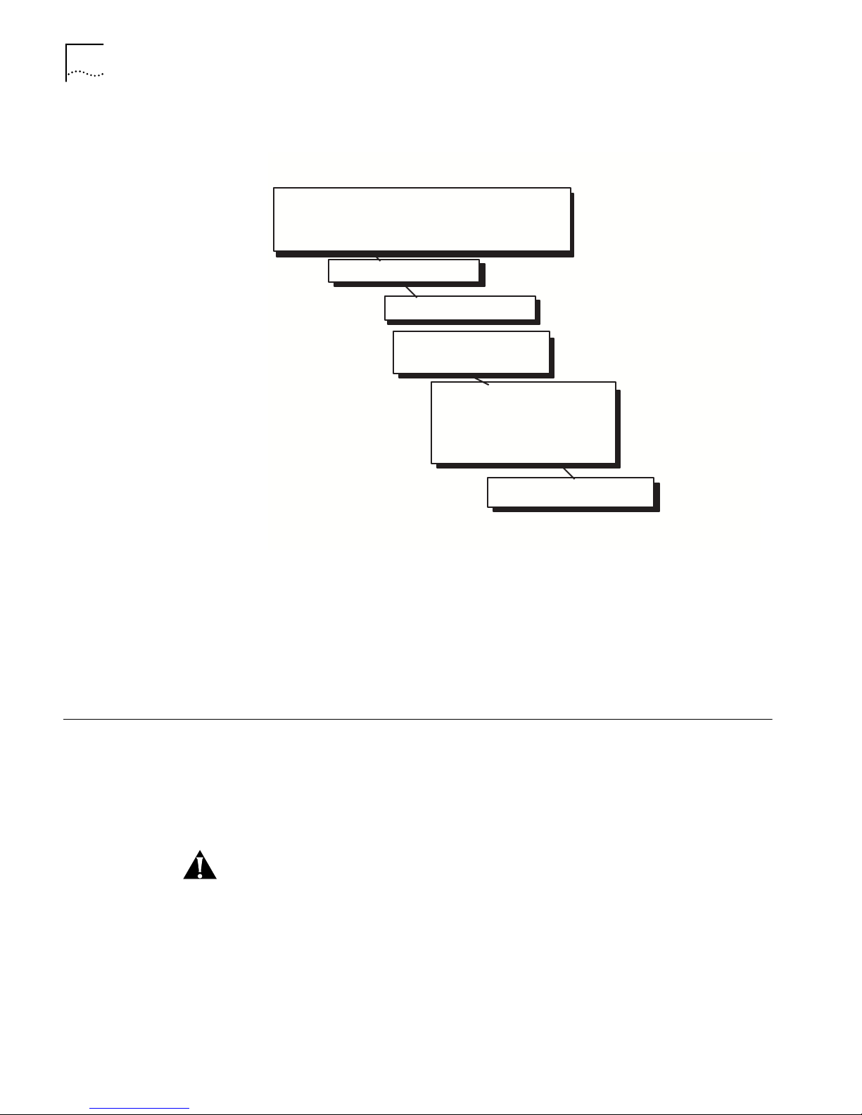
Installation Overview Figure 3 summarizes the overall installation procedure for the PathBuilder S600.
For details about each step in the overall procedure, see the following sections.
Page 30
30 CHAPTER 2: INSTALLATION
Figure 3 General Installation Procedure
Prepare the Site:
Verify Clearances Around the Shelf Site
Fabricate and Run Cabling and Wiring
Prepare AC or DC Power Run (Install Fuse and Alarm Panel)
Step 1
Install the Shelf in the Rack
Step 2
Step 3
Connect AC or DC Power
(If needed) Install Additional
Modules in the Shelf and
Monitor Front-Panel LEDs
Connect I/O Cabling and Wiring:
Step 4
Network Ports
Trunk Ports
Local Terminal
Office Alarms
BITS clock
Step 5
Connect a VT100 Terminal for
Local Management Access
Site Requirements n Be within the maximum distances to the port and trunk connections, as well as
the NMS terminal
n Have interconnect cabling and wiring ready and labeled
n Have a dedicated source of switched and fused AC power.
Step 1: Install the
Shelf in the Rack
n Provide clearance for making all connections and performing maintenance.
In a normal rack mount configuration the PathBuilder S600 shelf is 8.75" x 17.25"
x 11" including cables. Since the equipment is cooled with two internal fans,
clearance at the top is not needed. Convection cooled equipment should not be
mounted directly under the shelf but a least one rack unit below it. See Figure 4
for details. If the PathBuilder S600 is mounted in an enclosure, plan on enough
clearance at the front for cable and wiring service loops.
CAUTION: Many of the integrated circuits on the modules are sensitive to static
electricity. Do not handle the plug-in modules without wearing a properly
grounded, antistatic, wrist strap. When removing the modules from the shelf,
place them printed-circuit side down on a nonconducting, static-free, flat surface.
Page 31

Step 2: Connect AC or DC Power 31
To install the shelf in the rack, follow these steps:
1 Adjust the mounting ears, if necessary, for 19" installation. See Figure 4.
Figure 4 Rack Mounting Ear Configurations
19”
PathBuilder S600
5 Rows 8.75”
Caution: Weight
25 lbs
(Two People are
!
Recommended.)
Step 2: Connect AC or
DC Power
2 Support the shelf in its mounting place and attach the mounting hardware.
Since the unit weighs approximately 25 pounds, we recommend that two people
perform this step.
You make the input AC/DC power connections at the front of the PathBuilder
S600 shelf. Table 6 lists the specifications for the AC/DC Source.
Table 6 AC/DC Source Specifications
Input Power
Requirements
Power Consumption 200 Watts, Typical
Maximum Current 2.0 A @ 11v
90-264 VAC, 50-60Hz, Standard Grounded
Outlet for all PathBuilder S600s
Requirements
-42 to -52 VDC, Optional
14 AWG wire, Belden type 19364
1.0A @ 220V
3Com recommends that AC/DC power and office alarms be connected through a
Fuse and Alarm Panel mounted above the PathBuilder S600.
Page 32

32 CHAPTER 2: INSTALLATION
To make AC/DC power connections, follow these steps:
1 Plug the power supply modules directly into the backplane of the shelf. Their low
voltage DC outputs are bussed across the backplane to the other modules. Make
sure that the power supply modules and the fan tray are in the shelf and that they
are fully seated in their backplane connectors. (See Figure 5.)
The PathBuilder S600 supports dual redundant power supplies, but only one
Power Supply Module is required for operation.
Figure 5 Shelf Fill for AC/DC Power Application
Fan tray Power supply modules
AC
PathBuilder S600
Power
Input
DC
+
GND
-
CAUTION: Before servicing the unit and handling AC/DC power leads, disconnect
all power supply cords. Always have a partner close by who is familiar with first aid
for electrical shock.
WARNING: DC Units are to be installed only in Restricted Access Areas (dedicated
equipment rooms, equipment closets, etc.) in accordance with Articles 110-16 or
110-17, and 110-18 of the National Electrical Code, ANSI/NFDA No.70.
2 Turn off the AC/DC power source and connect the AC/DC leads to the front of the
shelf. Dress the leads to the rack leaving a service loop.
3 Turn on the AC/DC power and verify that the POWER indicators on both Power
Supply Modules are on and that the fans are running.
Step 3: (If needed)
Install Additional
Modules in the Shelf
The PathBuilder S600 ships with the factory-ordered modules installed. If you have
ordered additional modules, install them as described in this section; otherwise,
proceed to “Step 4: Connect I/O Cabling and Wiring” for instructions on how to
connect the factory-installed modules and verify front panel indicators.
n Install the Management CPU module in slot 1.
n Install the STX module in slot 2. (requires software release 2.00 or higher)
Page 33

Step 4: Connect I/O Cabling and Wiring 33
n Install any one of the following application modules in slot 3-6:
n DS3 UNI
n E3 UNI
n OC3/STM-1 UNI
n DS1 UNI with IMA
n E1 UNI with IMA
n Ethernet
n CBR DSX
n CBR-E1
n QSIM (Quad Serial Interface Module)
n HSIM (HSSI Module)
n FAM (Frame Access Module)
Step 4: Connect I/O
Cabling and Wiring
This section tells you how to connect I/O cabling and wiring once the modules are
installed in the shelf and describes the common and module-specific front panel
LEDs. Figure 6 shows an example of a PathBuilder S600 configuration with all of
the associated cabling connected.
Figure 6 Sample Full System Configuration
PathBuilder S600
Slot 6
Slot 5
Slot 4
DS3
Line
CSU or
CPE
Network
Management
Station
VT100 Terminal
Initial
Management
Connection to
Add an IP
Address for LAN
Management
T1 Timing
Source
Local
Alarm
System
Page 34

34 CHAPTER 2: INSTALLATION
Normal Start up
Sequence
All modules feature a set of five common system LEDs on the left side of the
module. When you install and connect a module, the common LED sequence
shown in Figure 7 occurs.
Power (PWR)—Indicates power from the power supply is good.
In Service (INS)—Indicates that the corresponding card is available for
transmission.
Fail—Indicates a sub-system failure.
Test—Indicates that a diagnostic is active.
Active (ACTV)—Indicates that the card is in service and active.
For descriptions of the LEDs specific to each module, see the following sections.
Figure 7 Common LED Sequence
PathBuilder S600
Connecting a DS3 UNI
Module
Slot 6
Slot 5
Slot 4
Slot 3
Slot 2
Slot 1
Power Inservice Fail Test
1.
2.
3.
Upon Power Up
Power On Tests Completed
Connect the DS3 UNI module to a DS3 repeater using the female BNC connectors.
Figure 8 shows a trunk module connection. The maximum coax run is 450 feet.
The transmitter in the DS3 UNI Module includes selectable LBO (Line Build-Out) to
adjust the output signal to cable runs of 0-255 or 225-450 feet. Select the LBO
during card configuration from the local terminal or NMS. See “Configuring the
DS3 UNI Module” in Chapter 5, for details.
Page 35

Figure 8 DS3 UNI Module Connection
PathBuilder S600
Step 4: Connect I/O Cabling and Wiring 35
Slot 6
Slot 5
Slot 4
RX
In
TX Out
TX In
DS3 Service
DS3
CSU or CPE
TX Out
75 ohm coax
0-225 ft or 225-450 ft
Once you have connected the module, verify the front-panel indicator sequence
illustrated in Figure 9. The DS3 UNI module features the following front panel
indicators in addition to the common system LEDs:
LOS (RED)—Powers up in the “off” state and illuminates when a LOS (Loss of
Signal) condition is detected on the incoming DS3. The LOS LED is off if a signal is
present. It reflects the LOS state of the DS3 in real time (no integration of the state
is needed).
A LOS condition sometimes occurs when the DS3 cell encapsulation (PLCP or
Clear) is set incorrectly. For details about setting DS3 cell encapsulation, see
“Configuring the DS3 UNI Module” in Chapter 5.
LOF (RED)—Powers up in the “off” state and illuminates when a LOF (Loss of
Frame) condition is detected on the incoming DS3. The LOF LED is off when the
signal is in frame. It reflects the LOF state of the DS3 in real time (no integration of
the state is needed).
LOCD (RED)—Powers up in the “off” state and illuminates when a LOCD (Loss of
Cell Delineation) condition is detected on the incoming DS3 under HEC (Header
Error Control) framing. The LOCD LED is off when delineations are obtained. It
reflects the LOCD state of the DS3 in real time (no integration of the state is
needed).
Page 36

36 CHAPTER 2: INSTALLATION
Figure 9 DS3 UNI Module LEDs
PathBuilder S600
Slot 6
Slot 5
Slot 4
Slot 3
Slot 2
Slot 1
Connecting an E3 UNI
Module
1.
2.
3.
Inservice Fail Test Active
Power
LOS
LOF LOCD
Power Up
Diagnostic Running
Power On Test Complete
Good DS3 / E3 / OC3-STM-1
Good ATM Cell Delineation
Connect the E3 UNI module to an E3 repeater using the female BNC connectors,
as shown in Figure 10. The maximum coax run is 1200 feet.
Figure 10 E3 UNI Module Connection
PathBuilder S600
Slot 6
Slot 5
Slot 4
E3
Service
TX Out
TX In
RX
In
E3
r PE
TX Out
75 ohm coax
Page 37

Step 4: Connect I/O Cabling and Wiring 37
Once you have connected the module, verify the front-panel indicator sequence.
The startup LED sequence and module-specific LEDs for the E3 UNI module are the
same as those for the D3 UNI module. See “Connecting a DS3 UNI Module”
above, for details.
Connecting an
OC3/STM-1 UNI
Trunk/Port Module
Connect the OC3/STM-1 UNI module using the Internal SC type connector. As
shown in Figure 11, the OC3-STM-1 UNI module supports two types of fiber optic
cable.
n Use multi-mode cable to generate UNI traffic over a port interface.
n Use single-mode cable to generate UNI traffic over a trunk interface.
Figure 11 OC3/STM-1 UNI Module Connection
PathBuilder S600
Slot 6
Slot 5
Slot 4
Connecting a DS1/E1
UNI with IMA Module
ATM
OC3 UNI Multi Mode Port
OC3 UNI Single Mode Trunk
Once you have connected the module, verify the front-panel indicator sequence.
The startup LED sequence and module-specific LEDs for the OC3/STM-1 UNI
module are the same as those for the D3 UNI module. See “Connecting a DS3 UNI
Module” earlier in this chapter, for details.
Connect the DS1 UNI with IMA module or the E1 UNI with IMA module using the
RJ-48 connectors (with integrated CSU for the DS1 module, with no CSU for the
E1 module), as shown in Figure 12.
If you are using a G703 coax physical connection to connect the E1 line to the
interface, you must use the E1 Balun Adapter (part number 3C63904) for proper
resistance.
Page 38

38 CHAPTER 2: INSTALLATION
Figure 12 DS1/E1 UNI with IMA Module Connection
PathBuilder S600
Slot 6
Slot 5
Slot 4
DS1/E1
ATM
n x T1 or E1
PathBuilder S600
PathBuilder S600
Once you have connected the module, verify the front-panel indicators. As shown
in Figure 13, the DS1/E1 UNI with IMA module features eight pairs of port
indicator LEDs in addition to the common system front panel indicators—each pair
corresponds to one of the eight RJ48 interfaces on the DS1/E1 UNI module.
Figure 13 DS1/E1 UNI LEDs
n The green indicator light illuminates to show that the port is in service.
n The red indicator light illuminates to show that the port is not in service.
Page 39

Step 4: Connect I/O Cabling and Wiring 39
Slot 6
Slot 5
Slot 4
PathBuilder S600
LAN
Connecting an Ethernet
Module
Connect an Ethernet module to the LAN directly or through a hub, as shown in
Figure 14, Table 7 lists the RJ48 connector pinouts.
Table 7 Ethernet Module Connector Pinouts
PIN 1 TX+
PIN 2 TX-)
PIN 3 RX+
PIN 4
PIN 5
PIN 6 RXPIN 7
PIN 8
The cable runs from the PathBuilder S600 Ethernet ports to the Ethernet LAN
connections must be no longer than 100 meters in compliance with EIA/TIA
standards for 10BaseT. The cable lengths should include service loops at the ends
and the complete cable route distances.
Figure 14 Ethernet Module Connection
Once you have connected the module, verify the front panel indicator sequence.
As shown in Figure 15, the Ethernet module has the following front panel
indicators in addition to the common system LEDs.
TX Port 1 (GREEN)—This is a transmit (to the cable) activity indicator. For each
frame sent to the cable, the LED is momentarily flashed.
Page 40

40 CHAPTER 2: INSTALLATION
RX Port 1 (GREEN)—This is a Receive (from the cable) activity indicator. For each
frame received from the cable, the LED will momentarily flash.
Link Port1 (GREEN)—This LED will illuminate when properly connected to the
Ethernet cable, otherwise it will be off.
TX Port 2 (GREEN)—This is a transmit (to the cable) activity indicator. For each
frame sent to the cable, the LED is momentarily flashed.
RX Port2 (GREEN)—This is a Receive (from the cable) activity indicator. For each
frame received from the cable, the LED will momentarily flash.
Link Port 2 (GREEN)—This LED will illuminate when properly connected to the
Ethernet cable, otherwise it will be off.
FWD (GREEN)—This is a bridging activity detector. For each frame bridged the
LED will momentarily flash.
ATM (GREEN)—This is an ATM traffic indicator. The use of this function will be
defined later.
Figure 15 Ethernet Module LEDs
PathBuilder S600
Common System
Power Inservice Fail Test
1.
2.
Fwd
ATM
Tx Rx Link Tx Rx Link
Slot 6
Slot 5
Slot 4
Slot 3
Slot 2
Slot 1
Power Up
Power On Test
Complete
Bridge
Data If
Blinking
Blinks
With
Data
Should Be On When Properly
Connected To 10BASE-T
Page 41

Step 4: Connect I/O Cabling and Wiring 41
Connecting a CBR DSX
or CBR E1 Port Module
Connect a CBR DSX or CBR E1 module using the RJ48 DSX interface for T1 traffic.
Table 8 describes the CBR DSXE1 connector pinouts.
Table 8 CBR DSX/E1 Connector Pinouts
PIN 1 RX (ring)
PIN 2 RX tip
PIN 3 NC
PIN 4 TX ring
PIN 5 TX tip
PIN 6 NC
PIN 7 NC
PIN 8 NC
If you are using a G703 coax physical connection to connect the CBR E1 line to the
interface, you must use the E1 Balun Adapter (part number 3C63904) for proper
resistance.
The CBR DSX module supports LBOs (LIne Build Outs) to CSU of up to 655 feet.
You must configure the LBO via the local terminal or NMS. See “Configuring the
CBR DSX (or E1) Modules” in Chapter 5, for details. You can typically make
connections locally to DTE equipment without DSU/CSUs, as long as the
equipment supports a direct T1 interface and can recover T1 signal. See Figure 16.
Figure 16 CBR DSX/E1 Module Connections
Channel
Bank
PBX
CSU
CBR DSX
or
E1 CBR
LBO
655 Ft.
PathBuilder S600
DS1 Structured for DS0
Drop and Insert or
Unstructured for DS1
Tunneling
You can make connections from the CBR E1 module locally to DTE equipment as
long as the equipment supports a direct E1 interface and can recover an E1 signal.
Once you have connected the CBR DSX or CBR E1 module, verify the front panel
indicator sequence illustrated in Figure 17.
Page 42

42 CHAPTER 2: INSTALLATION
Figure 17 CBR Module LEDs
Common System
Power Inservice Fail Test Active
1.
2.
3.
Port is
Out of
Service
Port is in
Service
Port Has OOF
or LOS
Condition
(Out of
Service)
Port is in
Service with
OOF or LOS
Condition
As shown in Figure 18, the CBR DSX/E1 module features eight pairs of port
indicator LEDs in addition to the common system front panel indicators—each pair
corresponds to one of the eight ports on the CBR DSX module.
n The green indicator light illuminates to show that the port has been placed in
service.
n The red indicator light illuminates to show an OOF or LOS condition on the
port.
Figure 18 CBR DSX LEDs
Install in Slot 4 - 6
18
PWR
INS
Connecting a QSIM
V.35/RS422/EIA530 Port
Module
The QSIM (Quad Serial Interface Module) provides the following cabling options:
n DTE/DCE V.35
n DTE/DCE EIA530
n DTE/DCE RS-422
n DTE/DCE X.21
FAIL
16 Port Indicator Lights
TEST
ACTV
Page 43

Step 4: Connect I/O Cabling and Wiring 43
To connect the QSIM, attach the appropriate cable to one of the four ports using
the 60-pin amphenol connector, as shown in Figure 19.
Figure 19 QSIM Connection
PathBuilder S600
Slot 6
Slot 5
Slot 4
Slot 3
V.35
EIA530
RS-422
Router
Table 9, Table 10, Table 11, Table 12, Table 13, Table 14, Table 15, Table 17, and
Table 16 describe the connector pinouts
Page 44

44 CHAPTER 2: INSTALLATION
Table 9 V.35 DTE Cable (60-pin Male to 34-pin Male; Part # 3C63913)
Signal Name
Pin # on 60 Pin
Conn
Pin # on V.35 Conn
Direction (For
QSIM)
Frame GND 46 A
Circuit GND 45 B
RTS 42 C Out
CTS 35 D In
DSR 34 E In
DCD 33 F In
DTR 43 H Out
LL (not used) 44 K Out
SD+ 18 P Out
SD- 17 S Out
RD+ 28 R In
RD- 27 T In
SCTE+ 20 U Out
SCTE- 19 W Out
SCR+ 26 V In
SCR- 25 X In
SCT+ 24 Y In
SCT- 23 AA In
Shorting GR 1 48, 49
Shorting GR 2 50, 51, 52
Shorting GR 3 53, 54, 55, 56
Page 45

Step 4: Connect I/O Cabling and Wiring 45
Table 10 V.35 DCE Cable Pinouts (60-pin Make to 34-pin Female; Part # 3C63914)
Signal Name
Pin # on 60 Pin
Conn
Pin # on V.35 Conn
Direction (For
QSIM)
Frame GND 46 A
Circuit GND 45 B
RTS 35 C In
CTS 42 D Out
DSR 43 E Out
DCD 44 F Out
DTR 34 H In
LL (not used) 33 K In
SD+ 28 P In
SD- 27 S In
RD+ 18 R Out
RD- 17 T Out
SCTE+ 26 U In
SCTE- 25 W In
SCR+ 22 V Out
SCR- 21 X Out
SCT+ 20 Y Out
SCT- 19 AA Out
Shorting GR 1 48, 49
Shorting GR 2 50, 51,
Shorting GR 3 53, 54, 55, 56
Page 46

46 CHAPTER 2: INSTALLATION
Table 11 RS-422/449 DTE Cable Pinouts (60-pin Male to RS-449 male; Part # 3C63920)
Signal Name
Pin # on 60 Pin
Conn
Pin # on V.35 Conn
Direction (For
QSIM)
Frame GND 46 1
Circuit GND 15, 16, 45 19, 20, 37
RTS 9, 10 7, 25 Out
CTS 1, 2 9, 27 In
DSR 3, 4 11, 29 In
DCD (not used, see
5, 6 13, 31 In
DCE cable)
DTR 7, 8 12, 30 Out
LL (not used) 44 10 Out
SD+ 11 4 Out
SD- 12 22 Out
RD+ 28 6 In
RD- 27 24 In
SCTE+ 13 17 Out
SCTE- 14 35 Out
SCR+ 26 8 In
SCR- 25 26 In
SCT+ 24 5 In
SCT- 23 23 In
Shorting GR 1 48, 49
Shorting GR 2 51, 52,
Page 47

Step 4: Connect I/O Cabling and Wiring 47
Table 12 RS422/449 DCE Cable Pinouts (60-pin Make to RS-449 Female; Part # 3C63921)
Signal Name
Pin # on 60 Pin
Conn
Pin # on V.35 Conn
Direction (For
QSIM)
Frame GND 46 1
Circuit GND 15, 16, 30 19, 20, 37
RTS 1, 2 7, 25 In
CTS 9, 10 9, 27 Out
DSR 7, 8 11, 29 Out
DCD 5, 6 13, 31 Out
DTR 3, 4 12, 30 In
LL (not used) 29 10 In
SD+ 28 4 In
SD- 27 22 In
RD+ 11 6 Out
RD- 12 24 Out
SCTE+ 26 17 In
SCTE- 25 35 In
SCR+ 24 8 Out
SCR- 23 26 Out
SCT+ 13 5 Out
SCT- 14 23 Out
Shorting GR 1 48, 49
Page 48

48 CHAPTER 2: INSTALLATION
Table 13 EIA530 DTE Cable Pinouts (60-pin Male to EIA530 Male; Part # 3C63923)
Signal Name
Pin # on 60 Pin
Conn
Pin # on V.35 Conn
Direction (For
QSIM)
Frame GND 46 1
Circuit GND 45 7
RTS 9, 10 4, 19 Out
CTS 1, 2 5, 13 In
DSR 3, 4 6, 22 In
DCD (not used, see
5, 6 8, 10 In
DCE cable)
DTR 7, 8 20, 23 Out
LL (not used) 44 18 Out
SD+ 11 2 Out
SD- 12 14 Out
RD+ 28 3 In
RD- 27 16 In
SCTE+ 13 24 Out
SCTE- 14 11 Out
SCR+ 26 17 In
SCR- 25 9 In
SCT+ 24 15 In
SCT- 23 12 In
Shorting GR 1 47, 48, 49
Shorting GR 2 51, 52,
Page 49

Step 4: Connect I/O Cabling and Wiring 49
Table 14 EIA530 DCE Cable Pinouts (60-pin Male to EIA530 Female; Part # 3C63922)
Signal Name
Pin # on 60 Pin
Conn
Pin # on V.35 Conn
Direction (For
QSIM)
Frame GND 46 1
Circuit GND 45 7
RTS 1, 2 4, 19 In
CTS 9, 10 5, 13 Out
DSR 7, 8 6, 22 Out
DCD (not used, see
5, 6 8, 10 Out
DCE cable)
DTR 3, 4 20, 23 In
LL (not used) 29 18 In
SD+ 28 2 In
SD- 27 14 In
RD+ 11 3 Out
RD- 12 16 Out
SCTE+ 26 24 In
SCTE- 25 11 In
SCR+ 24 17 Out
SCR- 23 9 Out
SCT+ 13 15 Out
SCT- 14 12 Out
Shorting GR 1 47, 48, 49
Page 50

50 CHAPTER 2: INSTALLATION
Table 15 HSSI straight DTE to DCE cable (50-pin Male to 50-pin Male; Part # 3C63912)
Signal Name Pin # on DCE Pin # on DTE Direction (For DTE)
Circuit GND 1, 7, 13, 19, 25,
26, 32, 38, 44,
1, 7, 13, 19, 25, 26, 32,
38, 44, 50
50
TA 8, 33 8,33 Out
CA 3, 28 3, 28 In
LA 10, 35 10, 35 In
LB 12, 37 12, 37 In
LC 5, 30 5, 30 Out
SD 11, 36 11, 36 Out
RD 4, 29 4, 29 In
TT 9, 34 9, 34 Out
RT 2, 27 2, 27 In
ST 6, 31 6, 31 In
ST DTE 14, 39 14, 39 Out
Ancillary to DTE
(not used)
20, 21, 22, 23,
24, 45, 46, 47,
20, 21, 22, 23, 24, 45,
46, 47, 48, 49
In
48, 49
Ancillary to DCE
(not used)
15, 16, 17, 18,
40, 41, 42, 43
15, 16, 17, 18, 40, 41,
42, 43
Out
Page 51

Step 4: Connect I/O Cabling and Wiring 51
Table 16 X.21 DTE cable (60 pin Male to 15-pin Male; Part # 3C63924)
Signal Name
Pin # on
60 PIN CONN
Pin # on DB15 CONN
Direction
(For QSIM)
Frame GND 46 1
Circuit GND 15 8
RTS 1, 2 3, 10 In
CTS 9, 10 5, 12 Out
DSR Out
DCD (in order to keep
Out
cable compatible with
Cisco, DCD should be
tristated when in DTE
mode.
DTR In
LL (not used) In
SD+ 28 2 In
SD- 27 9 In
RD+ 11 4 Out
RD- 12 11 Out
SCTE+ In
SCTE-1 In
SCR+ (in order to keep
24 6 Out
cable compatible with
Cisco, SCR+ & - should
be tristated when in
DTE mode, double
term, double buffer)
SCR- 23 13 Out
SCT+ Out
SCT- Out
Shorting GR 1 47, 48
Page 52

52 CHAPTER 2: INSTALLATION
Table 17 X.21 DCE Cable Pinouts (60-pin Male to 15-pin Female; Part # 3C63925)
Signal Name
Pin # on
60 PIN CONN
Pin # on DB15 CONN
Direction
(For QSIM)
Frame GND 46 1
Circuit GND 15 8
RTS 9, 10 3, 10 Out
CTS 1, 2 5, 12 In
DSR In
DCD (not used, see
In
DCE cable note)
DTR Out
LL (not used) Out
SD+ 11 2 Out
SD- 12 9 Out
RD+ 28 4 In
RD- 27 11 In
SCTE+ Out
SCTE- Out
SCR+ 26, 24 6 In
SCR- 25, 23 13 In
SCT+ In
SCT- In
Shorting GR 1 47, 48
Shorting GR 2 51, 52
Once you have connected the QSIM, verify the front panel indicators. As shown in
Figure 20, in addition to the common system front panel indicators, each port has
a pair of LEDs to the left of the port.
Figure 20 QSIM LEDs
Install in Slot 4 - 6
INS
PWR
FAIL
PWR = Power On
INS = Inservice
ENBL
CLK
TEST
PORT 4
PORT 3 PORT 2 PORT 1
60-Pin
Amphenol
Connector
ENBL—Illuminates when the port is in service.
CLK—Illuminates when clocking is in service.
Page 53

Step 4: Connect I/O Cabling and Wiring 53
Connecting a HSIM
Module
PWR
PWR = Power On
INS = Inservice
Connect a HSIM module using a HSSI SCSI-II 50-pin cable, as shown in Figure 21.
Once you have connected the HSIM module, verify the front panel indicators. As
shown in Figure 21, the HSIM module has two front panel indicators in addition to
the common system LEDs:
Inservice—Indicates that the HSIM card is active.
Not Used—Indicates that the HSIM card is not in use.
Figure 21 HSIM Connection and LEDs
Install in Slot 4 - 6
One HSSI
50 Pin SCSI-II
HSSI
INS
FAIL
TEST
Inservice
Not
Used
Connecting a DS1 Frame
Access Module
Router
Connect a Frame Access Module (FAM) using up to eight RJ48 interfaces for T1
traffic, as shown in Figure 22.
Once you have connected the FAM, verify the front panel indicator sequence
illustrated in Figure 22.
The FAM features eight pairs of port indicator LEDs in addition to the common
system front panel indicators—each pair corresponds to one of the eight ports on
the FAM.
Inservice—Indicates that the FAM card is active.
Not Used—Indicates that the FAM card is not in use.
Page 54

54 CHAPTER 2: INSTALLATION
Figure 22 FAM LEDs
Router
Verifying CPU LEDs and
Connecting the Office
Alarm Connector
PWR
INS
FAIL
TEST
ACTV
Inservice
Not Used
Common System
Power Inservice Fail
1.
2.
3.
n x 64K
Power Up/Or Failure
Test Diagnostics
Frame Relay
8 RJ 48 Interfaces
Normal Mode
The Management CPU module requires no external connections, but you must
verify the front panel indicator sequence illustrated in Figure 23.
In addition to the common front panel indicators, the Management CPU module
features the following LEDs:
Critical—Indicates a critical alarm.
Major—Indicates a major alarm.
Minor—Indicates a minor alarm.
ACO—Alarm Cut off; illuminates when you push the ACO button. ACO is
generally used in conjunction with an external alarm. When certain alarms are
generated, the external alarm rings. Pushing the ACO button cuts off the external
alarm and illuminates the ACO LED.
Page 55

Figure 23 Management CPU LEDs
PathBuilder S600
Slot 6
Slot 5
Slot 4
Slot 3
Slot 2
Common System CPU LEDs
Inservice Fail Test Active Critical Major Minor ACO
Power
1.
2.
Step 4: Connect I/O Cabling and Wiring 55
Power Up
Power On Test
Complete
Connecting the Office Alarm Connector
Figure 24 shows the office alarm connector on the Management CPU. The
PathBuilder S600 supports Alarm In and Alarm Out functions.
Figure 24 Office Alarm Connector
Major Alarm
External
Alarm
2
1
Ground
Normally Open
46
3
5
Major Alarm
Closure Enable
Minor Alarm
Normally Open
Minor Alarm
Closure Enable
Connect the alarm equipment to the appropriate pins, as determined by the type
of alarm equipment you are using. For example, if the alarm equipment you are
using requires OPEN state when there is no alarm and CLOSE state when the alarm
is activated, you would connect to Pin 4 and Pin 5.
Page 56

56 CHAPTER 2: INSTALLATION
Verifying STX LEDs and
Connecting the Optional
BITS Clock
The STX module requires no external connections, but you must verify the front
panel indicator sequence illustrated in Figure 25.
Figure 25 STX Module LEDs
PathBuilder S600
Power Inservice Fail Test Active
1.
2.
3.
Upon Power Up
Power On Tests Completed
Connecting the Optional BITS Clock (STX)
The PathBuilder S600 can receive or transmit a Bipolar Timing Source (BITS) clock
through the STX module. It offers the following options for the clock setting:
n T1 CSU
n DSX 0-133 feet
n DSX 133-266 feet
n DSX 266-399 feet
n DSX 399-533 feet
n DSX 533-655 feet
If desired, you can connect a BITS clock to the clock signal input or output port
located on the STX module using an RJ48 connector, as shown in Figure 26.
Page 57

Step 4: Connect I/O Cabling and Wiring 57
Figure 26 BITS Clock Connection (STX Module)
PathBuilder S600
Slot 6
Slot 5
Slot 4
1.544 Mbps
All Ones
RJ48 PIN 1 - Receive Ring
RJ48 PIN 2 - Receive Tip
1.544 Mbps
All Ones
RJ48 PIN 4 -Transmit Tip
RJ48 PIN 5 - Transmit Ring
Table 18 and Table 19 list the connector pinouts for the input and output
connectors.
Table 18 STX Module BITS Clock Input Connector Pinouts
PIN 1 Receive Ring
PIN 2 Receive Tip
PIN 3
PIN 4 Transmit Tip
PIN 5 Transmit Ring
PIN 6
PIN 7
PIN 8
Table 19 STX Module BITS Clock Output Connector Pinouts
PIN 1 Receive Ring
PIN 2 Receive Tip
PIN 3
PIN 4 Transmit Tip
PIN 5 Transmit Ring
PIN 6
PIN 7
PIN 8
This feature is currently available for North American, DSI, Standard carrier signals.
Page 58

58 CHAPTER 2: INSTALLATION
Step 5: Connect a
Management Terminal
In order to configure application connections and an IP address for SNMP support,
you must connect a management terminal to the PathBuilder S600. To do this, you
use the ports on the Management CPU module in slot 1 of the PathBuilder S600
shelf.
To connect a network management terminal, follow these steps:
1 Connect a VT 100 terminal to the RS-232 (console) port.
2 Use the VT100 terminal to input an IP address for the PathBuilder S600. See
“Setting up Communication Parameters” in Chapter 3, for details.
3 Establish communication between the PathBuilder S600 and any management
terminal in one of these ways:
n Direct RS-232 using the VT100 terminal or VT100 emulator, as described above
n Direct 10BaseT using an IP Telnet session
n SLIP or PPP over a dialup network using an IP Telnet session
Figure 27 illustrates the network management station terminal connection
options.
Figure 27 NMS Terminal Connection Options
LAN
SignalPin SignalPin
1 TX+
2 TX3 RX+
4 NC
RJ 45
5 NC
6 RX7 NC
8 NC
10BaseT
DTE
Female DB9
Pin Signal SignalPin
1 Frame Gnd
2 RX Data
3 TX Data
4 DTR
RS-232 SLIP
DTE DTE
RS 232 Null
Modem or
Crossover
Cable (50 Feet
or Less)
5 Signal Gnd
6 DSR
7 RTS
8&9 NC
ALARM
S
Straight Through
RS 232 Cable
DCE
Modem
(9600 Baud)
Dialup
Network
SLIP or
PPP
Modem
(9600 Baud)
NMS Terminal
(PC or W orkstation in
TELNET Session)
After you have connected the network management terminal, perform initial
configuration of the unit, as described in Chapter 3.
Local T erminal
(VT100)
NMS Terminal
(UNIX PC in
TELNET Session)
Page 59

GETTING STARTED
10BaseT
RS-232 SLIP
LAN
Dialup
Network
1 TX+
2 TX-
3 RX+
4 NC
5 NC
6 RX-
7 NC
8 NC
SignalPin SignalPin
1 Frame Gnd
2 RX Data
3 TX Data
4 DTR
5 Signal Gnd
6 DSR
7 RTS
8&9 NC
Pin Signal SignalPin
RJ 45
Female DB9
Local T erminal
DTE DTE
DTE
RS 232 Null
Modem or
Crossover
Cable (50 Feet
or Less)
NMS Terminal
Straight Through
RS 232 Cable
Modem
(9600 Baud)
Modem
(9600 Baud)
DCE
SLIP or
PPP
ALARM
S
10BaseT
RS-232 SLIP
LAN
Dialup
Network
1 TX+
2 TX3 RX+
4 NC
5 NC
6 RX7 NC
8 NC
SignalPin SignalPin
1 Frame Gnd
2 RX Data
3 TX Data
4 DTR
5 Signal Gnd
6 DSR
7 RTS
8&9 NC
Pin Signal SignalPin
NMS Terminal
(PC or W orkstation in
TELNET Session)
RJ 45
Female DB9
Local T erminal
(VT100)
DTE DTE
DTE
RS 232 Null
Modem or
Crossover
Cable (50 Feet
or Less)
NMS Terminal
(UNIX PC in
TELNET Session)
Straight Through
RS 232 Cable
Modem
(9600 Baud)
Modem
(9600 Baud)
DCE
SLIP or
PPP
ALARM
S
3
This chapter tells you how to log on to the PathBuilder® S600 WAN Access Switch
(PathBuilder S600), how to use the PathBuilder S600 menus, and how to perform
initial configuration using the NMS menus. It contains the following sections:
n Logging On
n Using the Menus
n Performing Initial Configuration
Logging On You enter initial configuration information via the local VT100 user interface. This
interface is preserved on a VT100 terminal connected to the RS-232 (console) port
on the Management CPU in slot 1 of the PathBuilder S600, as shown in Figure 28.
Set the terminal for the following:
n 9600 baud
n no parity
n 8 data bits
n 1 stop bit
Figure 28 NMS Terminal Connection Options
Page 60

60 CHAPTER 3: GETTING STARTED
When the PathBuilder S600 is powered up and operating, and your terminal is
connected, operating, and properly configured, the Text User Interface (TUI) title
screen shown in Figure 29 appears on your terminal.
Figure 29 PathBuilder S600 Text User Interface Title Screen
The TUI Title screen identifies the interface and its software release number and
prompts you for a password. Enter the default password:
password
If the software does not accept your password entry, try again. If the password still
not accepted, check with your system administrator to obtain the correct
password.
The Main menu, shown in Figure 30, appears.
Figure 30 PathBuilder S600 Main Menu
Page 61

Using the Menus 61
Use the options on the Main menu as follows:
n Select [1] System Administration to access common parameters.
n Select [2] Configuration Management to view or set configuration parameters.
n Select [3] Fault Management to view or acknowledge alarms and set
loopbacks.
n Select [4] Performance Management to view statistical data.
n Select [5] Exit to log out.
Using the Menus The title of the menu or display appears at the top of the screen. Your access
status appears in the upper righthand corner.
n Read-Write means that you have Read-Write control of the PathBuilder S600
and can make changes to the system.
n Read Only means that you can only monitor the menus and displays.
Navigating through the
Menus
Understanding the
Menu Hierarchy
You select a menu option by typing the selection number and pressing [Enter].
Displays that contain information and no selections include the prompt:
Press Esc for previous menu
Multi-page displays also prompt you to press “N” for the next page or “P” for the
previous page.
Only the Main menu contains the Exit selection to log out. Selecting Exit returns
you to the title screen with the password prompt. All other menus have a Previous
Menu selection which returns you to the Main menu one screen at a time. You can
also press [Esc] to move back one menu at a time.
The auto logout feature automatically logs you out and returns you to the title
screen if you do not press a key for a specified time (1 - 99 minutes). To set the
autolog timeout, select [1] System Administration from the Main menu, then
select [1] General System Information, then select [6] Set Auto Logout Time.
The PathBuilder S600 menu hierarchy includes several layers of menus. Each
submenu has a name that is the same or similar to the name of the option that
displays it. For example, selecting [2] Configuration Management on the Main
Menu displays a submenu titled Configuration Management, and selecting [4]
Manage System Clock from the System Administration menu displays a submenu
titled System Clock Configuration.
You can then select options on the submenus to display additional submenus or
prompts that allow you to set various parameters. The options that appear on
some submenus vary, depending on what modules you have installed. For
example, the System Clock Configuration menu includes a Set CBR option only if
you have installed a CBR module, a Set DS3 option only if you have installed a DS3
UNI module, a Set IMA option only if you have installed a DS1 UNI or E1 UNI
module, and so on.
Page 62

62 CHAPTER 3: GETTING STARTED
Using the Menus to
Change Settings
Settings are displayed in prompts at the bottom of the menus. For example, if you
select:
[2] Configuration Management
[1] Manage Card
[3] DS3 UNI (may be different choice number, depending upon your shelf
configuration)
[1] Card Information
[5] Set ATM Payload Scramble
The following prompt appears at the bottom of the DS3 UNI Configuration menu:
Enter ATM Payload Scramble (1=No,2=Yes):
When you type a selection number and press [Enter], payload scrambling is
disabled or enabled, and the prompt is cleared.
Alarm Indicator If the PathBuilder S600 detects an alarm condition, an alarm indicator (the
highlighted word “Alarm”) appears to the left of the access status on every menu
and display, as shown in Figure 31.
Figure 31 Alarm Indicator
Indicates that an
Select to display
current alarms
alarm has been
detected
After you acknowledge the alarm, the alarm indicator is no longer highlighted, but
the word “Alarm” remains in the upper right corner of the screen to indicate that
an alarm has been acknowledged.
When the alarm is acknowledged and the condition that caused the alarm is
cleared, the indicator disappears entirely. If a menu indicates that an alarm has
been acknowledged and a new alarm occurs, the Alarm indicator is highlighted
again.
See “Managing System Alarms” in Chapter 6 for instructions on acknowledging
alarms.
Page 63

Performing Initial Configuration 63
Performing Initial
Configuration
After you install the PathBuilder S600 hardware, you must complete the following
three steps in order to complete the initial configuration:
1 Set up communication parameters
2 Configure In-band Management (optional)
3 Set up passwords
4 Set the time and date
You access the menus used to perform these steps from the System
Administration menu, shown in Figure 32. To display the System Administration
menu:
From the Main menu, select [1] System Administration.
Figure 32 System Administration Menu
The following subsections provide instructions for performing the three initial
configuration steps. See Chapter 5 for instructions on configuring specific
PathBuilder S600 modules.
Setting up
Communication
Parameters
In order for the PathBuilder S600 to communicate to the Ethernet network, you
must set the correct communication parameters. To do this, select [3] Manage IP
Network Configuration from the System Administration menu to display the
Manage IP Network Configuration menu, shown in Figure 33.
Page 64

64 CHAPTER 3: GETTING STARTED
Figure 33 Manage IP Network Configuration Menu
From the Manage IP Network Configuration menu, you configure the following:
n Local host IP address
n Trap client
n Default gateway
The subsections following the figure describe how to set these parameters.
Once you have entered the IP address and SNMP information for the PathBuilder
S600 on the VT100 terminal, you can continue configuring the device on the local
console, or you can configure the PathBuilder S600 through either the 10BaseT or
the SLIP/PPP dialup port on the Management CPU module using either a Telnet
session or an SNMP manager such as PathBuilder Switch Manager. See Figure 34.
Page 65

Performing Initial Configuration 65
Figure 34 PathBuilder S600 Terminal Access Methods
SNMP
160.160.1.3
Telnet
160.160.1.2
SNMP
SNMP
160.160.1.1
10BaseT
SLIP or PPP
or
Telnet
160.160.1.4
PathBuilder S600
Mgmt
Module
Dialup
Port
Mask 255.255.255.0
RS 232
Direct
RS 232
9600 Bps
ATM
160.160.1.5
Telnet
160.160.1.6
VT100
Configuring the Local Host IP Address
The Local Host IP Address Configuration menu allows you to set parameters for
the management port (Ethernet or SLIP) or the PathBuilder S600.
To enter configure the Ethernet management port, follow these steps:
1 From the Manage IP Network Configuration menu, select [1] Local Host IP
Configuration to display the Local Host IP Configuration menu, shown in
Figure 35.
Figure 35 Local Host IP Configuration Menu
Page 66

66 CHAPTER 3: GETTING STARTED
2 Select [1] Ethernet Port IP Configuration to display the Ethernet Port IP
When you apply a change to the Local Host IP Configuration menu, you might get
logged out if you are using a Telnet session. The default configuration is Baud rate:
9600, Parity; none, Data Bits:8, StopBits:1.
Configuration menu, shown in Figure 36.
Figure 36 Ethernet Port IP Configuration Menu
3 Enter the following information (by selecting the appropriate options and
responding to the prompts that appear at the bottom of the screen) to enable IP
Ethernet connectors:
IP Address—Provided by the network administrator. This is the IP address of the
PathBuilder S600 Management CPU.
You should consult the network administrator to obtain an IP address for the
PathBuilder S600 which will allow its 10BaseT Management port to co-exist with
hosts on its local LAN.
Subnet Mask—Provided by the network administrator. The subnet mask
identifies the subnetwork containing the PathBuilder S600 Ethernet management
port.
Community Name—Enter “3Com” (The community name applies to Ethernet
port IP configuration only.)
Figure 37 shows a sample PathBuilder S600 IP host setup.
Page 67

Figure 37 Sample PathBuilder S600 IP Host Setup
PathBuilder S600
PathBuilder
S600
192.73.30.99
Performing Initial Configuration 67
192.73.30.100
3Com
Community
4 Select [4] Previous Menu to return to the Local Host IP Configuration menu.
5 Select [3] Apply IP Configuration Changes to activate the IP address. The following
prompt appears:
This action will terminate all running TELNET/SNMP sessions.
Are you sure you want to apply IP configuration changes (Y/N)[N]?
6 Enter [Y] to apply your changes.
To enter configure the SLIP management port, follow these steps:
1 From the Manage IP Network Configuration menu, select [1] Local Host IP
Configuration to display the Local Host IP Configuration menu, shown earlier in
Figure 35.
When you apply a change to this menu, you might get logged out if you are using
a Telnet session. The default configuration is Baud rate: 9600, Parity; none, Data
Bits:8, StopBits:1.
2 Select [2] SLIP Port IP Configuration to display the SLIP Port IP Configuration menu,
shown in Figure 38.
Figure 38 SLIP Port IP Configuration Menu
Page 68

68 CHAPTER 3: GETTING STARTED
3 Enter the following information (by selecting the appropriate options and
4 Select [3] Previous Menu to return to the Local Host IP Configuration menu.
5 Select [3] Apply IP Configuration Changes to activate the IP address. The following
6 Enter [Y] to apply your changes.
responding to the prompts that appear at the bottom of the screen) to enable IP
Ethernet connectors:
IP Address—Provided by the network administrator. This is the IP address of the
PathBuilder S600 Management CPU.
You should consult the network administrator to obtain an IP address for the
PathBuilder S600 which will allow its 10BaseT Management port to co-exist with
hosts on its local LAN.
Subnet Mask—Provided by the network administrator. The subnet mask
identifies the subnetwork containing the PathBuilder S600 SLIP management port.
prompt appears:
This action will terminate all running TELNET/SNMP sessions.
Are you sure you want to apply IP configuration changes (Y/N)[N]?
Configuring Trap Clients
The PathBuilder S600 can report SNMP trap alarms to a remote management
system. Trap clients are the network management stations to which you want the
PathBuilder S600 to send traps. You can specify up to four trap clients. To
configure trap clients, follow these steps:
1 From the Manage IP Network Configuration menu, select [2] Trap Client
Configuration to display the Trap Client Configuration menu, shown in Figure 39.
Figure 39 Trap Client Configuration Menu
2 Select the number corresponding to the trap client you want to configure.
Figure 40 shows the menu for configuring trap client 1.
Page 69

Performing Initial Configuration 69
Figure 40 Trap Client 1 Configuration Menu
3 Enter the following information (by selecting the appropriate options and
responding to the prompts that appear at the bottom of the screen) to configure
the trap client:
IP Address—The IP address of the network management station to which you
want the PathBuilder S600 to send traps.
Subnet Mask—The subnet mask for the network management station to which
you want the PathBuilder S600 to send traps.
Port Number—The system-defined port number. You should not modify this
number.
4 Select [4] Previous Menu to return to the Trap Client Configuration menu.
5 Select [5] Previous Menu to return to the Manage IP Network Configuration menu.
Configuring the Default Gateway
The default gateway routes IP data to non-local networks (Telnet sessions from
different subnetworks). To configure the default gateway, follow these steps:
1 From the Manage IP Network Configuration menu, select [3] Default Gateway
Configuration to display the Default Gateway Configuration menu, shown in
Figure 41.
2 Enter the following information (by selecting the appropriate options and
responding to the prompts that appear at the bottom of the screen) to configure
the default gateway:
IP Address—The IP address of the router which you want to configure as the
default gateway.
Subnet Mask—The subnet mask for the router which you want to configure as
the default gateway.
Page 70

70 CHAPTER 3: GETTING STARTED
3 Select [3] Previous Menu to return to the Manage IP Network Configuration menu.
Figure 41 Default Gateway Configuration Menu
Configuring In-band
Management
4 Select [4] Previous Menu to return to the System Administration menu.
In addition to managing the PathBuilder S600 out-of-band, you can also manage
the unit in-band in one of the following ways:
n via the 10Base-T port on the near-end MCPU card (up to four VCs maximum)
n via the near-end Dual Ethernet module
For detailed instructions on configuring PVCs, see “Configuring Virtual Circuits” in
Chapter 5.
In-band Management via the 10Base-T Port on the Near-end MCPU Card
To configure in-band management via the 10Base-T port on the near-end MCPU
card, follow these steps:
If you use this method, you must use a new subnet with each PathBuilder S600
and a new static route for each new subnet on the management station or router.
You are also limited to managing up to four remote units from the central
management unit,
1 Build a PVC on the near-end PathBuilder S600 from the MCPU to the OC3 UNI
(slot 1 to slot 3), setting the following parameters on the Add Virtual Circuit
screen:
traffic shaper—Choose any of the available values (for example, 10Mbps).
IP address—This address must be different than the local host IP address.
subnet mask—Specify any acceptable address (for example, 255.255.255.0).
VPI/VCI—Enter any values in the accepted range (for example, 10/100).
Page 71

Performing Initial Configuration 71
2 Build a PVC on the far-end PathBuilder S600 from the MCPU to the OC3 UNI (slot
1 to slot 3), setting the following parameters on the Add Virtual Circuit screen:
traffic shaper—Choose any of the available values (for example 17M).
IP address—You must use a different subnet than the one you used for the
near-end PathBuilder S600.
subnet mask—Specify any acceptable address (for example, 255.255.255.0).
VPI/VCI—You must use the same values as you did for the near-end PathBuilder
S600.
3 On the System Administration menu, set the following:
a Set the default gateway on the far-end PathBuilder S600 to the PVC IP address
you set for the near-end PathBuilder S600 in step 1.
b Set the default gateway on the management station to the local host IP address
of the near-end PathBuilder S600.
For details about setting the default gateway, see “Configuring the Default
Gateway” earlier in this chapter.
4 Apply your IP configuration changes.
a From the main menu, select [1] System Administration.
b From the System Administration menu, select [3] Manage IP Network
Configuration.
c From the Manage IP Network Configuration menu, select [1] Local Host IP
Configuration.
d From the Local Host IP Configuration menu, select [3] Apply IP Configuration
Changes.
In-band Management via the Near-end Dual Ethernet Module
To configure in-band management via the near-end PathBuilder S600 Dual
Ethernet module, follow these steps:
If you use this method, you can manage one PathBuilder S600 in a point-to-point
configuration or as many as 256 remote PathBuilder S600s if all the units are
connected to an ATM network service provided by a local or large Telco
organization.
1 Build a PVC on the near-end PathBuilder S600 from the Dual Ethernet Module
(port 1 or 2) to the OC3 UNI (for example, from slot 4 to slot 3), setting the
following parameters on the Add Virtual Circuit screen:
traffic shaper—Choose any of the available values (for example 17M)
VPI/VCI—Enter any values in the accepted range (for example, 10/101).
2 Attach a hub or Ethernet NIC directly to the Dual Ethernet Module port.
3 Build a PVC on the far-end PathBuilder S600 from the MCPU to the OC3 UNI (slot
1 to slot 3), setting the following parameters on the Add Virtual Circuit screen:
traffic shaper—Choose any of the available values (for example 17M)
IP address—Specify any acceptable address (for example, 192.198.65.3).
subnet mask—Specify any acceptable address (for example, 255.255.255.0).
VPI/VCI—You must use the same values as you did for the near-end PathBuilder
S600.
Page 72

72 CHAPTER 3: GETTING STARTED
4 Apply your IP configuration changes.
a From the main menu, select [1] System Administration.
b From the System Administration menu, select [3] Manage IP Network
Configuration.
c From the Manage IP Network Configuration menu, select [1] Local Host IP
Configuration.
d From the Local Host IP Configuration menu, select [3] Apply IP Configuration
Changes.
Setting up a Password To replace the default password for the PathBuilder S600 with one of your own
choosing, follow these steps:
1 From the System Administration menu, select [1] General System Information to
display the General System Information menu, shown in Figure 42.
Figure 42 General System Information Menu
2 Select [7] Set Password. The following prompt appears at the bottom of the
screen:
Enter New Password:
3 Enter the new password. It can be any combination of up to eight alphanumeric
characters. For security, asterisks are displayed for the new password characters as
you enter them.
4 Respond to the confirmation prompt by entering the new password a second
time.
When you select a new password, record it and store the record in a safe place.
You will not be able to access the NMS menus without it. If you do lose access to
the menus for this reason, contact the 3Com Technical Assistance Center.
5 Select [8] Previous Menu to return to the System Administration menu.
Page 73

Performing Initial Configuration 73
Setting the Time and
Date
By setting the correct time and date, you ensure accurate alarm reporting by the
NMS software. To set the time and date, follow these steps:
1 From the System Administration menu, select [2] Manage Time and Date to
display the Time and Date Configuration menu, shown in Figure 43.
Figure 43 Time and Date Configuration Menu
The current date and time are displayed above the menu options.
2 Select [1] Set Date. The following prompt appears at the bottom of the screen:
Enter Date (mm/dd/yy)
3 Enter the date.
4 Select [2] Set Time. The following prompt appears at the bottom of the screen:
Enter Time (hh:mm:ss):
5 Enter the time.
Type a time a few seconds in advance of the current time, then press [Enter] when
the current time matches the time you typed.
6 Select [3] Previous Menu to return to the System Administration menu.
7 Select [12] Previous Menu to return to the Main menu.
Page 74

74 CHAPTER 3: GETTING STARTED
Page 75

PATHBUILDER S600 MODULE AND
4
System Module
Overview
A
PPLICATION OVERVIEW
This chapter describes the features and operation of each of the modules and
applications supported by the PathBuilder S600 WAN Access Switch PathBuilder
S600 ATM Multiservices Access Platform (PathBuilder S600). It contains the
following sections:
n System Module Overview
n ATM Module Overview
n Application Module Overview
n Application Overview
For specifications for the PathBuilder S600 modules, see “Specifications” in
Chapter 1.
The PathBuilder S600 includes the following two system modules:
n Management Central Processing Unit (MCPU) module
®
Management CPU
Module
n STX Module
The MCPU module, located in slot 1 of the PathBuilder S600 shelf, performs all
configuration, monitoring and user interface functions. It features the following:
n Management processor
n Two RS-232 interfaces (one for terminal interface and one for SLIP/PPP
interface)
n Ethernet port (for management of the PathBuilder S600 via the network)
n CPU memory consisting of a real time clock, battery backup RAM, and dual
FLASH. The dual FLASH is used so that the code can be upgraded and two
copies of the code can be stored at one time. The CPU can run either copy of
the code under user control and the CPU code can be upgraded on-line.
n One relay contact for Major Audible Alarm. This alarm relay is normally open. It
indicates a major alarm upon power failure, or whenever the CPU determines
there is a major Alarm. An ACO push button is provided to cut off the alarm
(open the relay). The CPU also accepts one external alarm from outside
equipment for which the alarm indication is activated when the input pins are
shorted.
n A SAR interfacing an ATM bus. The SAR is used for communication and
signaling. It can send and receive packets from the ATM network under CPU
control. The user interface allows you to enter management VCs in the same
way any other VC is entered. Management VCs terminate on the CPU SAR.
Page 76

76 CHAPTER 4: PATHBUILDER S600 MODULE AND APPLICATION OVERVIEW
n User interface software that allows you to interface to the system in multiple
ways:
n Through an RS-232 port for direct VT100 Connection. The CPU contains the
VT100 drivers to control the management and user interface screens.
n Through a second RS-232 port to run SLIP/PPP. This port can connect via a
modem to the user management network. You can then run a Telnet
session to access the NMS screens.
n Through the direct Ethernet connection. You can then run a Telnet session
to access the NMS screens.
n SNMP support via the RS232 SLIP/PPP and the Ethernet connection. The
PathBuilder S600 supports multiple standard MIBs for the bridge, Ethernet and
DS3 functions. It also supports an Enterprise MIB that allows you to configure
and monitor the unit using an SNMP-based Enterprise management system
such as Transcend.
The CPU stores all the code that runs on the system and runs diagnostics at
bootup to check the integrity of the system.
SNMP MIB Standards Support
Table 20 lists the standards that are supported for the MIBs.
Table 20 Supported MIBs
RFC 1493 Bridge MIB (Previously RFC 1286)
RFC 1407 DS3/E3 MIB
RFC 1643 Ethernet MIB
RFC 1406 DS1/E1 MIB
RFC 1595 SONET MIB
RFC 1213 MIB II
STX Module The STX module provides a switching matrix that supports sophisticated traffic
management, priority queuing, and multicasting. It performs all functions
necessary for concentrating and switching ATM cells according to the set priority
given to its Class of Service traffic types:
n Provides any-to-any switching based on VC address
n Introduces Virtual Interfaces (VIs) which are logical UNI ports. Up to 24 VIs are
supported per module.
n Supports Deep buffers (192,000 per module) for queuing to support 4 Classes
of Services per VI
n Provides priority queuing in which each VC can be assigned to a specific VI
which then can be allocated to one of 4 queues for CBR, VBR-rt, VBR-nrt, and
UBR classes of service.
n Supports Per VC and/or VP traffic shaping
n Supports per VC traffic policing
n Supports multicasting (up to 256 connections with 32 leaves)
n Supports per VC statistics
n Allows a total of 8,000 connections maximum per PathBuilder S600
Page 77

ATM Module Overview 77
Q0 = 500 cell buffer
Q1 = 1500 cell buffer
Q2 = 3000 cell buffer
Q3 = 3000 cell buffer
Traffic
Shaper
Physical
Por t
Cell Bus
"Virtual
Interfaces"
1
2
3
.
.
.
.
.
.
.
.
24
Queue Controller
Cell buffers
CBR
VBR
n Generates the backplane timing 8KHZ clock and generates ATM bus timing
n Accepts an 8kHZ signal from all modules together with a 1.544MHz external
BITs Clock
Priority Queuing
The PathBuilder S600 with STX provides separate cell buffer queues per virtual
interface. You can assign multiple VCs to each virtual interface and map them to
the desired queue. The STX services the queues in order: queue 0, then queue 1,
then queue 2 and queue 3. Figure 44 illustrates this priority queuing.
If the STX finds data in a higher queue while it is servicing another queue, it
services the higher queue, thereby maintaining the priority. For example, if the STX
finds data in queue 0 while it is servicing queue 2, the STX services queue 0. By
queuing the VCs in this way, the STX ensures that the Class of Service is
maintained.
The ensuing traffic from the queues is then shaped according to the traffic
shaping parameter that you set (64Kbps to 155 Mbps) in cells per second. In
addition, each circuit can be policed based on the congestion threshold that you
set for each of the queues. You can also specify the actions that you want to be
taken if a queue is found to be congested based on the threshold you have set.
Figure 44 PathBuilder S600 with STX Priority Queuing
ATM Module
Overview
The PathBuilder S600 supports the following application modules with ATM
interfaces:
n DS3 UNI
n E3 UNI
n OC3/STM-1 UNI
n DS1 UNI with IMA
n E1 UNI with IMA
Page 78

78 CHAPTER 4: PATHBUILDER S600 MODULE AND APPLICATION OVERVIEW
DS3 UNI Module
Overview
E3 UNI Module
Overview
OC3/STM-1 Module
Overview
The DS3 module is compatible with AT&T Publication 54014 specifications, uses
the unchannelized format, and is compliant to M23 or the C-bit parity ANSI-107a,
1991 specifications. It performs the following key functions:
n Provides line interface functions and terminates the FEAC and MDL for the
C-bit format
n Performs ATM to physical layer mapping and adds PLCP according to UNI 3.0
n Performs peak traffic shaping on the transmit (14 bulk shapers)
n Performs ATM address translation
The E3 UNI module is typically used for terminating/accessing public or private
WAN services. However, depending on your local applications, you can also use
this module in the port slot for taking local traffic across the WAN.
The E3 UNI module performs the following key functions:
n Performs ATM to physical layer mapping
n Performs peak traffic shaping on the transmit (14 bulk shapers)
n Performs ATM Address Translation
There are two versions of the OC3/STM-1 module: multimode fiber and single
mode fiber. The multimode fiber module is typically used for connecting ATM LAN
equipment such as 3Com CoreBuilder 7000. The single mode fiber module is
typically used for WAN ATM services, providing a longer reach in terms of distance.
Both version support the European SDH framed optical networks (STM-1).
DS1/E1 Module
Overview
Application Module
Overview
The OC3/STM-1 UNI module provides an ATM connection at up to 155 Mpbs and,
like other UNI modules, it supports multiple traffic shaper values.
The DS1/E1 UNI module provides Inverse Multiplexing of ATM cell streams over
multiple T1/E1 physical links, based on the industry standard ATM Forum
Specification. It provides the following key benefits:
n Uses a cell-based multiplexing technique to convert a single ATM stream into
multiple lower speed ATM streams to be sent over independent links and
retrieve the initial ATM cell stream from the links at the far end
n Preserves cell order from end-to-end in the ATM layer
n Supports up to 8 DS1/E1 ports (n = 1 to 8)
n Supports multiple IMA groups
n Supports differential delay tolerance up to 70ms for DS1 and 56ms for E1
n Handles link addition/deletion, failure/recovery with minimal disruption
The PathBuilder S600 supports the following application modules:
n Ethernet (Dual Ethernet Module)
n CBR (CBR DSX, CBR E1)
n Frame Relay (QSIM, HSIM, FAM)
Page 79

Application Module Overview 79
Ethernet Module
Overview
The Ethernet module (Dual Ethernet) is a port or application module that takes
legacy LAN traffic across a WAN ATM network using the PathBuilder S600. This
module is used to connect LAN segments and bridge or IP forward traffic across
the ATM network to a LAN/IP service.
The Ethernet module supports two 10BaseT Ethernet connections. It provides a
bridge function together with a SAR conversion to ATM cells. The Ethernet module
performs the following key functions:
n Provides line interface for two 10BaseT Ethernet connections.
n Performs bridge function and encapsulation according to RFC1483 with
multicast support.
n Performs segmentation and assembly to ATM, with 14 programmable traffic
shapers on the transmit (PCR, SCR, MBS settings available).
n Provides a wire speed forwarding rate of 14700 packets per port.
n Supports Spanning Tree
Ethernet Module Standards Support
Table 21 lists the standards currently supported by the Ethernet module.
Table 21 Supported Ethernet RFC Standards
RFC 1483 Multiprotocol Encapsulation Over ATM Adaptation Layer 5
RFC 826 ARP
RFC 1042 Standard for the Transmission of IP Datagrams over IEEE 802 Networks
RFC 1577 Operation for ATM ARP and In ARP, LLC/SNAP Encapsulation of IP, etc.
Ethernet Module Operation
The Ethernet module contains a high-performance CPU that performs all the
bridging and packet switching functions. The Ethernet CPU communicates to the
management CPU. Specific module information (serial number, type, MAC
address etc.) is stored and accessed through the management CPU. After bootup,
the local CPU requests actual run code from the management CPU.
Figure 45 shows a functional block diagram for the Ethernet module.
The data flow in the Ethernet module is as follows:
n Packets appearing on the 10BaseT ports from the LAN are checked for packet
integrity and stored in the shared memory area. Up to a Megabyte of memory
is reserved for data.
n The CPU examines the packet's header in memory and a bridge operation is
performed to determine if the packet goes on the WAN. See “Bridging”, later
in this chapter, for details about the bridge operation.
n If the packet is to go on the WAN, the bridge determines the VCC connection
for the packet destination.
n The packet is then encapsulated according to RFC 1483 and the descriptor is
handed off to the SAR together with the associated ATM header descriptor.
n The SAR append the AAL5 convergence sublayer to the packets and queues
the packets according the shaper you specify for that connection in the user
interface.
Page 80

80 CHAPTER 4: PATHBUILDER S600 MODULE AND APPLICATION OVERVIEW
Figure 45 PathBuilder S600 Ethernet Block Diagram
PathBuilder
S600
PathBuilder S600
DS3
PathBuilder
S600
Ethernet
Input
MAC Address to VP.VC Map
02608C123456 = DS3, 0.35
Bridge
Function
VP.VC
DS3
VP.VC
ATM
Network
DS3
PathBuilder S600
PathBuilder
S600
The data does not move from memory from the time it is received till the time it is
segmented. This guarantees maximum performance of the system.
n On the opposite side, cells are received from the DS3 UNI, or other ATM
module, side through the STX module.
n The SAR then assembles the cells belonging to the connections specified for it
and the CPU is given confirmation for the cells that are assembled.
n The bridge function of the CPU examines the packet header, removes the
encapsulations, and forwards the packet to the proper destination after
learning the address and updating the bridge table. For further information on
bridging, see “Bridging” later in this chapter.
CBR DSX/E1 Module
Overview
The PathBuilder S600 supports two CBR modules: CBR DSX and CBR E1. These
modules are port or application modules for connecting devices such as PBXs
(Private Branch eXchanges), video codecs, DSU/CSUs, T1 multiplexers, and channel
banks for connection over an ATM WAN service.
CBR DSX Module
The CBR service module provides four or eight DSX DS1 ports for transit over an
ATM network. The DSX DS1 inputs can be either ESF or SF using B8ZS or AMI. The
received frame can be tunneled through the ATM network using DS1 unstructured
mode or broken up into its DS0 and AB signaling components using DS1
structured mode. The structured mode allows DS0 mid span drop and insert or
grooming.
Structured and unstructured modes comply with ATM Forum AF-SAA-0032.000.
This service maps the DS1 service through AAL1 adaptation layer over a CBR
virtual channel connection (VCC). The VCC is established as a permanent virtual
circuit (PVC) and mapped from the PathBuilder S600s ATM port to either another
PathBuilder WAN access switch or an ATM Forum circuit emulation compliant
device.
Page 81

Application Module Overview 81
The emulated circuit connection from the CBR DSX port to a remote CBR DSX port
is accomplished by mapping DS1 circuits to Permanent Virtual Circuits. These
circuits will then be transmitted through the ATM network to the destination port.
For details on configuring the PVC, see “Configuring Virtual Circuits”” in
Chapter 5.
Cell Delay Variation is compensated for by the PathBuilder S600 through an
adaptive receive buffer. This buffer can provide consistent synchronous delivery of
DS1 service by building in delay in excess of ATM cell delay and outputting from a
receive buffer. You can configure the adaptive delay.
Dynamic Bandwidth Allocation Through dynamic bandwidth allocation, the
CBR DSX module can de-activate the CBR PVC and free up network access
bandwidth for other uses. See “Dynamic Bandwidth Allocation (DS0 Signaling)”,
later in this chapter, for details.
CBR DSX Module Standards Support Table 22 lists the ATM standards
supported by the CBR DSX module.
Table 22 CBR DSX Module ATM Forum/ANSI/ITU-T Supported Standards
AF-SAA-0032.000 ATM Forum Circuit Emulation Service (CES)
ANSI T1.630/ITU-T I.363 AAL1 Unstructured Data Transfer Mode
CBR E1 Module
The CBR E1 module features four or eight E1 ports for transit over an ATM
network. It provides a circuit emulator service mapped to ATM cells. The E1 inputs
can be either single or multi-frame using HDB3 line coding. The received frame
can be tunneled through the ATM network using E1 unstructured mode or broken
up into its DS0 and ABCD signaling components using E1 structured mode. The
structured mode allows DS0 mid span drop and insert or grooming.
The structured and unstructured mode comply with ATM Forum
AF-SAA-0032.000. This service maps the E1 service through AAL1 adaptation
layer over a CBR virtual channel connection (VCC). The VCC is established as a
permanent virtual circuit (PVC) and mapped from the PathBuilder S600s ATM port
to either another PathBuilder S600 or an ATM Forum circuit emulation compliant
device.
Network Cell Delay Variation is compensated for by the PathBuilder S600 through
an adaptive receive buffer. This buffer can provide consistent synchronous delivery
of E1 service by building in delay in excess of ATM cell delay and outputting from a
receive buffer. The adaptive delay is configurable.
CBR E1 Module Standards Support Table 23 lists the standards supported by
the CBR E1 module.
Table 23 CBR E1 Module ATM Forum/ANSI/ITU-T Supported Standards
AF-SAA-0032.000 ATM Forum Circuit Emulation Service (CES)
ANSI T1.630/ITU-T I.363 AAL1 Unstructured Data Transfer Mode
Page 82

82 CHAPTER 4: PATHBUILDER S600 MODULE AND APPLICATION OVERVIEW
QSIM/HSIM/FAM
Module Overview
The PathBuilder S600 supports three Frame Relay modules: QSIM, HSIM, and FAM.
These modules are port, or application, modules for connecting non-ATM devices
to ATM services. Typical device applications include FRADs (Frame Relay Assembler
and Disassembler or Frame Relay Access Devices), channel extenders, FEPs
(Front-End Processors), and routers.
The HSIM module is used to interconnect terminals to DCE devices that must
operate between 3 and 20Mbps.
Table 24 summarizes the basic features of the three Frame Relay modules.
Table 24 PathBuilder S600 Frame Relay Modules
Module Acronym # of ports Type of ports
Quad Serial Interface
Module
HSSI Module HSIM 1 HSSI (20 Mbps)
Frame Access Module FAM 8 T1 (64K to 1.5 Mbps)
QSIM 4 V.35, RS449, EIA 530, X.21
(64K to 8 Mbps)
Each of the Frame Relay modules provides a number of serial interfaces and an
ATM SAR and is able to perform cell-to-frame as well as frame-to-cell conversion.
Frames received from the HDLC serial interfaces are segmented in to cells by SAR
and passed to the ATM backplane. In the other direction, cells received from ATM
backplane will be reassembled into frames and passed to the HDLC serial
interfaces.
A RISC processor on the Frame Relay module performs these functions:
n management CPU (MCPU) communication
n hardware device configuration
n frame/cell conversion
n permanent virtual circuit management
n alarm generation
n statistical data collection.
The SAR contains 15 traffic shapers, each of which can be programmed for
sustained cell rate of transmission, peak cell rate, and maximum burst size.
The traffic shapers work as follows:
n The packet is segmented using a dual leaky buffer algorithm, whereby the cells
are transmitted from each connection in the shaper at an average rate until the
bucket of tokens fills up (a token is given to the connection at an average rate
if it has no cells to transmit at that moment).
n The shaper then turns the burst mode on and transmits at the peak rate for a
burst length. Note that the shaper serves every connection independently.
n PCR, SCR, and MBS settings are available.
Page 83

Application Overview 83
Application Overview This section describes the following applications that are supported by the
PathBuilder S600:
n Bridging
n Spanning Tree
n CBR application
n Ethernet and voice application
n Frame application
See the following subsections for details.
Bridging The bridge function is an integral part of the Ethernet module. The PathBuilder
S600 supports ATM permanent virtual circuits (PVCs) for access to the ATM
network. These PVCs connect an PathBuilder S600 Ethernet port through the ATM
network to another PathBuilder S600 Ethernet port. All the PVCs configured for a
port will form a virtual Bridged Ethernet network to all other ports at the other
end of the PVC.
The bridge operation is equivalent to a multiport bridge. The two Ethernet ports
on the module are treated separately unless they are connected through the ATM
network via PVCs. The ATM Layer operates transparently under the datalink layer
to allow higher level protocols to run without changes.
The CPU examines each packet's headers while they are in memory and performs
the bridging operations. A bridge is configured and maintained for each slot and
port in the PathBuilder S600. The bridge maintains the following:
n A forwarding table in its memory that lists the source and destination addresses
contained in each packet that passes through the PathBuilder S600
n An aging timer that removes addresses from the forwarding table if an address
is not used for a configured time
n A configured list of protocols, source addresses, and destination addresses that
will be rejected by the bridge. For information on configuring bridging filters,
see “Configuring the Bridge”” in Chapter 5.
The bridge learns and builds forwarding tables for every PVC that is tied to that
port. When a packet is received on the port or any PVC tied to that port, the
Source MAC address is learned and kept in the forwarding table until the aging
timer expires. You can also use the user interface to add static forwarding
addresses that the bridge will not delete after the aging timer expires.
When the packet arrives, the bridge looks up the destination MAC address to
determine the destination of the packet from the forwarding tables. If the
destination is found, the bridge forwards the packet to the correct destination. If
the destination is not found, the bridge broadcasts or floods the packet on all
PVCs that are tied to the particular port. If you have assigned a multicast PVC for
that particular port, the bridge will forward the packet to the port multicast VC
instead of broadcasting it.
The PathBuilder S600 performs LLC-based multiplexing per RFC 1483 and
Ethernet frames are bridged. In the first phase, PathBuilder S600 does not support
frames bigger than Ethernet maximum frame size (1518) or IEEE 802.3 frame size
Page 84

84 CHAPTER 4: PATHBUILDER S600 MODULE AND APPLICATION OVERVIEW
(1492) bytes (+ framing bytes) coming off the ATM network. Token ring and FDDI
frames higher than these MTU sizes are dropped and statistics about these frame
drops are reported through VT-100 and SNMP (through bridge MIB).
Filtering
The first bridging operation determines if the packet is to be processed and
transmitted across the bridge or filtered out based on the list of protocols and
addresses input as part of the PathBuilder S600 configuration. Filtering gives you
control over who communicates with whom in the network. The CPU reads the
header of each packet to determine the protocol, source address, and destination
address and then looks in the list to see if the packet should be passed through
the bridge. If it is to be filtered out, it is cleared from memory.
Addressing
The next bridging operation determines if a packet is addressed to another unit on
the LAN (in which case it can be rejected) or if it is addressed to a unit across the
bridge.
As mentioned above, each Ethernet packet includes a source address and a
destination address in its header. These are MAC addresses which are unique
physical addresses assigned to every Ethernet interface on every Ethernet LAN.
Packet transmission from one unit to another on the same LAN is accomplished
easily. However, packet transmission between units on different LANs requires a
higher-level addressing scheme.
Virtual Circuits
ATM networks are organized into virtual circuits or logical duplex paths between
two ATM unit ports, as shown in Figure 46.
Figure 46 Virtual Circuit Scheme
Transmission
Path
Virtual
Circuit
Virtual
Circuit
Each transmission direction in a virtual circuit is referred to as a virtual channel.
Virtual channels are then grouped into virtual paths between two ports. The
channels and paths are assigned numbers: VPIs (Virtual Path Indicators) and VCIs
(Virtual Channel Indicators). Each ATM cell (a fixed-length unit of data over ATM)
is assigned to a virtual circuit by including the circuit's VPI/VCI in the cell's header.
This is then used to steer the cell through an ATM unit and the ATM network.
VCI 1 (Transmit)
{
VCI 1 (Receive)
VCIs
VCIs
VCI 1 (Transmit)
{
VCI 1 (Receive)
{
{
VPI 1
VPI 2
VPI 3
VPI 1
Transmission
Path
Page 85

Application Overview 85
Figure 47 illustrates virtual circuits on a simple network using PathBuilder S600s.
Figure 47 Virtual Circuits in a Simple Network
Workstation 1
LAN
AA
LAN
AB
S4P1
PathBuilder S600
S5P1
PathBuilder S600 A
VPI/VCI 1/33
DS3 UNI
VPI/VCI
2/35
S4P2
PathBuilder
S600
S5P2
LAN
AA
LAN
BB
Workstation 2
Suppose workstation 1 on LAN AA wants to send data to workstation 2 on LAN
BB. It transmits Ethernet packets which include its MAC address and that of
workstation 2. PathBuilder S600 A groups the packets into cells and, since it does
not know where workstation 2 is, broadcasts the cells on all VPI/VCIs.
PathBuilder S600 B learns that workstation 1 transmits to its slot 4 port 2 over
VPI/VCI 1/33 and to slot 5 port 2 over VPI/VCI 2/35. This information is then stored
in forwarding tables in PathBuilder S600 B.
When workstation 2 responds, it includes its MAC address and that of workstation
1 in the packets. PathBuilder S600 B looks in the appropriate forwarding table and
finds that it can reach workstation 1 on VPI/VCI 2/5. When the first response cell
on 2/35 is formatted back into packets at PathBuilder S600 A, PathBuilder S600 B
learns how to reach workstation 2 without broadcasting.
Learning Bridge
The aggregate of VPIs/VCIs assigned to a slot and port (Ethernet connection) of
the PathBuilder S600 is referred to as a bridge. Since the PathBuilder S600 reads
and stores MAC addresses and associated VPIs/VCIs as described above, the bridge
is called a learning bridge. Each learning bridge of the PathBuilder S600 has a
separate forwarding table containing the MAC addresses to VPI/VCI associations.
When a learned entry is stored in a forwarding table, it is time tagged. An aging
timer in the PathBuilder S600, which you can set, purges entries from the
forwarding tables after the specified time. The bridges must then relearn purged
addresses. This controls the size of the forwarding tables, particularly in large
networks.
In the PathBuilder S600, each bridge also has a static table associated with it. You
can enter MAC addresses and corresponding PVCs into the static table that you do
not want to be affected by the aging timer. These entries might be for LAN units
Page 86

86 CHAPTER 4: PATHBUILDER S600 MODULE AND APPLICATION OVERVIEW
that are permanent and are accessed through the ATM network frequently, such
as servers.
The example in Figure 47 shows only one transmission path: the DS3 UNI between
the two PathBuilder S600s. As a result, cells leaving PathBuilder S600 A on VPI/VCI
1/33 arrive at PathBuilder S600 B on VPI/VCI 1/33. If the DS3 trunk were switched
through a standard telephone switching system to interconnect many PathBuilder
S600s, each PathBuilder S600 would have to have the same VPI/VCI designations
assigned. The ATM switch removes this restriction.
Figure 48 shows several PathBuilder S600s in an ATM-switched network. The
switch maps one VPI/VCI into another based on the destination of the packets in
the cell, in the process learning the complete topology of the network. Each
PathBuilder S600 connected to the switch can be configured independently.
Figure 48 Virtual Circuits in a Switched Network
PathBuilder S600 A
PathBuilder S600
VPI/VCI 1/3
PathBuilder S600 B
PathBuilder S600
PathBuilder S600 C
PathBuilder S600
VPI/VCI 10/23
ATM
Switch
VPI/VCI 4/6
Segmentation
Once the CPU determines that a packet should go across the bridge, it
encapsulates the packet per RFC 1483 and adds a pad and trailer conforming to
AAL5 (ATM Adaption Layer 5) at the end of the packet (see Figure 49). The trailer
is fixed at eight bytes and contains information such as the new length of the
packet and cyclic redundancy check bytes (CRC facilitates error checking at the
receive end). The pad is set to 0 to 47 bytes to make the full packet length
including the trailer divisible by 48 bytes. The packet with the RFC 1483
encapsulation is then segmented into 48-byte (384-bit) cells by the SAR function.
Figure 49 AAL5 Pad and Trailer
Trailer
The cells are assigned to a virtual circuit defined between the incoming and
outgoing ports based on the destination address of the original packet. A 5-byte
header containing the virtual circuit assignment along with other information is
added to each cell. The cells are queued in the output FIFO (First In First Out)
memory of the Ethernet Module based on the bandwidth and quality of service
Ethernet Packet
PAD
(0-47 Bytes)
Reserved
2 Bytes
Length
2 Bytes
CRC
4 Bytes
Page 87

Application Overview 87
requirements assigned to the virtual circuit at configuration. The FIFO provides
elastic storage between the Ethernet Module and the STX module which may be
polling and multiplexing up to three Ethernet modules.
Reassembly
When the STX Module receives a cell from the DS3 UNI Module (or other ATM
module), it broadcasts it to all Ethernet Module ports. As cells are received by the
reassembler, their header is read by the CPU to determine if they belong to the
port. If so, the header is stripped and the cell is stored in memory appended to the
previous ones for that virtual circuit.
The CPU also looks for the AAL5 trailer that signifies the end of a packet. When it
finds a trailer, it performs the CRC calculation, checks the length of the cells since
the previous trailer to be sure no cells were missed, strips the trailer, appends the
cell to the others to reform the original packet, and sends the packet through the
Ethernet I/F to the LAN.
Spanning Tree Spanning Tree (IEEE 802.1d) is a technique that detects loops in a network and
logically blocks the redundant paths, ensuring that only one route exists between
any two LANs. It eliminates the duplication of packets and provides fault tolerance
for resilient networks.
As the Spanning Tree is being constructed, bridges exchange information, which is
transmitted in packets called Configuration Bridge Protocol Data Units (C-BPDUs).
During this process, the Spanning Tree Algorithm and Protocol (STAP) module
elects a root bridge in order to establish a stable spanning tree topology. The root
bridge determines the spanning tree topology and controls which bridges block
packets and which forward packets.
Once the topology is stable, all STAP bridges listen for special “Hello” C-BPDUs
transmitted from the root bridge at regular intervals (usually every two seconds). If
a STAP bridge timer expires before receiving a “Hello” C-BPDU, it assumes that the
root bridge, or a link between itself and the root bridge, has gone down. It then
initiates a reconfiguration of the Spanning Tree.
When a port goes down (for instance, when an ATM VC is deleted), the port card
notifies the STAP module of such a change. The STAP module then reinitiates the
process of electing a root bridge, and the Spanning Tree calculation process begins
all over again.
Spanning Tree Operation
The Spanning Tree operates as follows:
For more detailed information about how the Spanning Tree operates, see
IEEE802.1d.
n An STAP module runs as a task on the management card. This task is
n Spanning Tree Bridge configuration Protocol Data Units (BPDUs) are received at
responsible for maintaining all data structures for Spanning Tree operation for
all ports and for sending/receiving Spanning Tree configuration packets.
Ethernet port cards (on Ethernet and ATM ports) and are sent to the STAP
module on the management card.
Page 88

88 CHAPTER 4: PATHBUILDER S600 MODULE AND APPLICATION OVERVIEW
n The management card STAP module examines the packet, reads the MAC
address of the sender, and analyzes the costs reported by the sender.
n When state of a port changes, the STAP module notifies the port card of the
change.
n When a port card receives change information for a port, it updates the
operational state of the port so as to change the bridging operation on the
port. For instance, if a port in a forwarding state (normal operation mode of
receiving and forwarding packets) is discovered to be forming a loop, it can be
put in a blocking state. Once the port goes in the blocking state, the port card
will stop receiving frames on the port.
Spanning Tree Instances
The Spanning Tree logic supports a maximum of 255 physical and virtual ports,
thereby allowing a maximum of 254 ATM VCs. (One Ethernet port is required be
set aside for other purposes.)
For the purpose of Spanning Tree operation, each set of one Ethernet port and its
associated ATM VCs is treated as one bridge entity. The STAP module runs a
separate instance for each bridge entity. Since the PathBuilder S600 shelf can be
filled with a maximum of three Ethernet cards, each with two Ethernet ports, a
maximum of six instances of STAP can be running on the management card.
Each STAP instance runs independently of the other STAP instances and processes
configuration packets as if they came from a different physical bridge device. This
approach helps segregate Ethernet ports completely for the purposes of bridging
and Spanning Tree and enables the PathBuilder S600 to operate as six separate
bridges.
VC-VC Bridging operation The Ethernet module supports full-mesh bridging
between its Ethernet port and all of its associated VCs. This bridging must be
bidirectional and should be conditional upon the operational status of the
Spanning Tree. If Spanning Tree operation is disabled, VC-VC bridging is not
necessary since the PathBuilder S600 is not expected to forward traffic coming
from the ATM network.
For instructions on enabling and disabling the Spanning Tree, see “Enabling and
Disabling the Spanning Tree” in Chapter 5.
CBR Application The CBR module consists of 8 DSX T1 interfaces capable of accepting superframe
or extended superframe DS1 inputs. The DS1 signal is then mapped over a
Constant Bit Rate (CBR) virtual channel. Encapsulation of the T1 within the ATM
service is based on the ATM Forum (AF-SAA-0032.000) Circuit Emulation Service
Interoperability specification. The ATM Forum specification designates two modes
of operation:
Structured —Modeled after fractional T1. Only the timeslots which will be used
are sent.
Unstructured —Merely encapsulates the entire DS1 onto an ATM path. It allows
timing and FDL to pass through.
Page 89

Application Overview 89
Power
CBR
DS0 = 5
DS1
ATM Network
Drop
and
Insert
DS0 = 5 VP = 0 VC = 35
ATM
Structured/CBR
Public Switched
Telephone
Network
DS0 = 5
Power
CBR
Structured Frame
DS0 = 5
ESF
DS1
Channel
Bank
ATM Trunk
DS1
ATM Network
Drop
and
Insert
DS0 = 5 VP = 0 VC = 35
ATM
Structured/CBR
Public Switched
Telephone
Network
DS0 = 5
Structured DS1
Implement the structured service if you require DS0 midspan drop-and-insert. See
Figure 50.
Figure 50 CBR Structured DS1 - Drop and Insert
Midspan drop and insert allows services such as public switched telephone service
to be inserted into the ATM link. Combining this service with Ethernet bridge
service provides you with a complete integrated communications access solution.
See Figure 51.
Figure 51 Integrated PathBuilder S600 Application
PBX or Key
Ethernet
System
PathBuilder S600
LAN
DS0 = 6
DS0 = 1-6
Voice
Drop
LAN
Data
Public Switched
Telephone
Network
ATM Network
PBX or Key
System
PathBuilder S600
Ethernet
LAN
Page 90

90 CHAPTER 4: PATHBUILDER S600 MODULE AND APPLICATION OVERVIEW
Drop-and-Insert DS0 channels can also be allowed to transit the entire path. This
provides DS0 to DS0 connectivity between end locations. Structured DS0s can be
groomed to be combined through an ATM network allowing end to end DS0
switching as shown in Figure 52.
Figure 52 Structured DS0 Combining
PathBuilder S600
DS1
10 DS0
10 DS0
PathBuilder S600
Structured DS0
Grooming
PathBuilder S600
DS1
ATM Network
Up to 24 Timeslots
PBX - Private Branch Exchange
VCC - Virtual Channel Connection
Dynamic Bandwidth Allocation (DS0 Signaling)
Structured DS0s provide channel associated signaling (CAS) by providing a path
for DS0 A and B bits. See Figure 53.
Channel associated signalling allows telephone supervision to be signaled end to
end. Note that structured DS1 CBR occupies only the needed bandwidth for the
DS0s selected.
Figure 53 Channel Associated Signaling
These frames are then followed by the ABCD bits of each active DS0. Two DS0s
ABCD bits are provided in each byte after the last DS0 group. Figure 54 illustrates
an example of 3 DS0s and their ABCD bits sent in a structured encapsulation.
Channel
Bank
PathBuilder S600
DS0
PathBuilder S600
A&B Bits
Channel Associated
Signaling (CAS)
Page 91

Application Overview 91
e
f
Figure 54 Multiframe Structure for 3x64kbit/s DS1 or E1 with CAS
AAL1 Pointer
Pointer
ABCD for
First
Transported
Timeslot
ABCD for
Third
for
Transported
Timeslot
orted
lot
. . .
. . .
ABCD for Second
Transported Timeslot
First Transported Octet of Multiframe
Second Transported Octet of Multifram
First 125 µsec Frame of Multiframe for
DS1
First Transported Octet of Multiframe
Second 125 µsec Frame of Multiframe
Second Transported Octet of Multiframe
DS1
First 125 µsec Frame of Multiframe for
DS1
Last 125 µsec Frame of Multiframe for
Second 125 µsec Frame of Multiframe for
DS1
DS1
Signaling
Substructure
Last 125 µsec Frame of Multiframe for
DS1
The PathBuilder S600 CBR module can detect the AB bits on the CAS to activate
or de-activate the CBR PVC.
n When an off-hook signal is detected, the CBR PVC is activated.
n When an on-hook signal is detected, the CBR PVC is deactivated, freeing up
the network access bandwidth for other uses (such as VBR traffic). This is the
basis for dynamic bandwidth allocation.
Note that a structured DS1 channel will not pass the original DS1 frame to the
remote end. For instance, ESF network management will terminate at the
PathBuilder S600 on a structured DS1, so CSU to CSU Facility Data Link (FDL)
communication will not be possible. FDL communication is possible with
unstructured DS1.
Unstructured DS1
Implement unstructured DS1 service when you want DS1 tunneling through an
ATM system. DS1 tunneling allows an entire DS1 frame including framing bits to
transit an ATM networks. See Figure 55.
Page 92

92 CHAPTER 4: PATHBUILDER S600 MODULE AND APPLICATION OVERVIEW
Figure 55 DS1 Unstructured Tunneling
T1
Unstructured
Data
Service
Unit
PathBuilder S600
ATM Network
Data
Service
Unit
PathBuilder S600
Channel
Service
Unit
Channel
Service
Unit
DS1 Signal Tunneled Through a PVC
Use unstructured services when DS0 midspan access is not required and end to
end DS1 service is required, for example to provide CSU or DSU end to end
connectivity. The encapsulation of unstructured DS1 occupies DS1 bandwidth on
the VCC and uses AAL 1 SAR, as shown in Figure 56.
Figure 56 AAL1 Structured DS1
Unstructured DS1
DS1 Frame
Structured DS1
FEC for SN/CSI
Lost Cell
Detection
Clock Recovery
DS0 DS0
CSI SN SNP
BLANK A & B
SAR-SDU
Signaling
A/D Converter
AAL Layer
SAR
AAL 1
VCC
47 Bytes1 Bit 3 Bits 4 Bits
ATM Header
5 Bytes 48 Bytes
CSI - Convergence Sublayer Indicator
FEC - Forward Error Correction
SNP - Sequence Number Protection
SN - Sequence Number
SAR - SDU - Segmentation and Reassembly Service Data Unit
VCC - Virtual Channel Connection
AAL 1 Data
ATM Layer
Page 93

Application Overview 93
DS1
ESF
FDL
AAL 1 DS0 DS0 DS0 DS0 A&B
DS1 Structured N x 64 Kbps
Bit
Bucket
PathBuilder S600 Interface
DS1
ESF
FDL
AAL 1 DS1
DS1 Unstructured
PathBuilder S600 Interface
DTE
Timing
DS1 = 1,544 Mbps
DS0 = 64 Kbps
DS - Digital Signal
ESF - Extended Superframe
Structured versus Unstructured Summary
Use Table 25 to select whether to use structured or unstructured DS1 CBR.
Table 25 Selecting Structured Mode Versus Unstructured Mode
Structured Unstructured
DSO midspan drop and
insert
DSO access grooming X
DS1 network
management end to end
DS1 end to end
(no DSO access)
DS1 CBR 1.544 Mbps of
bandwidth
Dynamic Bandwidth
Allocation (DBA)
X
X X
X X
X X
X
Figure 57 depicts the effects of structured versus unstructured service on the
DS1/E1 framing.
Figure 57 Structured Versus Unstructured Effects on Transit DS1
Ethernet and Voice
Application
A typical configuration involves multiple PathBuilder S600s connected through an
ATM network that could consist an ATM switch or an ATM network consisting of
multiple switches. This configuration is shown in Figure 58.
Page 94

94 CHAPTER 4: PATHBUILDER S600 MODULE AND APPLICATION OVERVIEW
d
Figure 58 Typical PathBuilder S600 Configuration
CSU #1
Unstructured Input
LAN
PathBuilder S600
1
PathBuilder S600 #1
DS1 Tunnel Through
Unstructured DS1 CBR
Port P1
DS3 UNI 1
CSU #2
ATM
Switched
Network
DS0 Drop and Insert
Via Structured DS1
CBR
PathBuilder S600 #3
LAN
PathBuilder S600
2
PathBuilder S600 #2
Port P2
Port P3
DS3 UNI 3
PathBuilder S600
DS3 UNI 2
PBX 3
CSU #3
LAN
3
CSU #4
PBX 2
Structure
Input
Circuits Set Up on The PathBuilder S600 #1 Circuits Set Up on the PathBuilder S600 #2
PVC END1 END2 VPI/VCI Conn To PVC END1 END2 VPI/VCI Conn To
#1 LAN1 DS3 0/200 LAN2 #1 LAN2 DS3 01/100 LAN1
#2 LAN1 DS3 0/300 LAN3 #2 LAN2 DS3 0/300 LAN3
#3 CSU1 DS3 0/500 CSU4 #3 PBX2 DS3 0/400 PBX3
Circuits Set Up By The Carrier (Cross Connects) Circuits Set Up on the PathBuilder S600 #3
PVC END1 VPI/VCI1 END2 VPI/VCI2 PVC END1 END2 VPI/VCI Conn To
#1 P1 0/200 P2 0/100 #1 LAN3 DS3 0/100 LAN1
#2 P1 0/300 P3 0/100 #2 LAN3 DS3 0/200 LAN2
#3 P2 0/300 P3 0/200 #3 PBX3 DS3 0/300 PBX2
#4 P2 0/400 P3 0/300 #4 CSU4 DS3 0/500 CSU1
#5 P1 0/500 P3 0/500
Forward and Reverse VCCs Match in This Example. VCCs are Unidirectional. Only Forward Vccs are Shown for
Easier Viewing.
Figure 59 shows three PathBuilder S600s connected through a carrier ATM
network or a private switch. The ATM switch or network should be configured
with Permanent Virtual Circuits (PVCs) connecting one LAN or DS1 port on one
PathBuilder S600 to another port on another PathBuilder S600.
Page 95

Application Overview 95
PathBuilder S600 B
Ethernet
Port
Bridge VP0/200
VP0/300
DS3
UNI
VP0/200
VP0/300
02608C456123
02608C123456
ATM
MAC Address
Forward Table
ATM
Network
PathBuilder S600 A
02608C123456
02608C456123
PathBuilder S600 C
PathBuilder S600
PathBuilder S600
Note that the numbers given for these circuits by the carrier are local to one
PathBuilder S600 and have no global significance. For example, VCC number
0/100 is used on two different PathBuilder S600s to mean two different circuits.
The carrier will assign each PathBuilder S600 at each location any number of
circuits to connect each PathBuilder S600 Ethernet port to any other PathBuilder
S600 Ethernet port desired.
The connections in the carrier network are shown for illustration only. Figure 59
shows an example for an ATM switch configuration. Note that the VCC numbers
get translated by the ATM switch since they have local meaning only for every
switch port. For example, the carrier would provide the PathBuilder S600 at the #1
location, four VCCs for the forward and reverse path to connect respectively to
LAN2 and LAN3. VCCs are unidirectional; therefore, two VCCs are designated on
a port of an PathBuilder S600 to transmit to, and receive from, another location.
The PVCs are provisioned by the carrier for use on each PathBuilder S600. These
PVCs are entered in circuit tables within each PathBuilder S600. After these circuits
are built the bridge can use this information to send ATM cells to remote sites.
The PathBuilder S600 supports a maximum of 768 VCs. You first configure each
PathBuilder S600 with the PVC information using menus that prompt you to input
specific information about each Permanent Virtual Circuit. See “Configuring
Virtual Circuits” in Chapter 5, for details.
These PVCs are tied to specific PathBuilder S600 ports (Ethernet slot 4, port 1).
You can associate several PVCs associated to one PathBuilder S600 port. Each PVC
represents the logical circuit being used to connect one PathBuilder S600 port to a
remote PathBuilder S600 port.
Once you have entered all PVCs, the bridge learns the network addresses for the
local and remote sites and starts bridging packets to the correct destination by
segmenting the packets into cells which are destined to a remote PathBuilder
S600 port. See Figure 59. The ATM network will transport the cells according to
the VPI/VCI headers.
Figure 59 ATM Bridging
Page 96

96 CHAPTER 4: PATHBUILDER S600 MODULE AND APPLICATION OVERVIEW
Figure 60 shows three PathBuilder S600s configured to provide LAN connectivity
between three different LAN segments. This example is a simple configuration
which only uses 1 port on 1 Ethernet port card in each PathBuilder S600.
Figure 60 LAN Connectivity
Circuits Set Up on PathBuilder S600 #2
PVC END1 END2 VPI/VCI Conn To
#1 LAN2 DS3 0/100 LAN1
#2 LAN2 DS3 0/300 LAN3
LAN
1
Bridge
Table
PathBuilder S600
Forward Known
DS3 UNI 1
Broadcast
Unknown
PathBuilder
S600 #1
Circuits Set Up on PathBuilder S600 #1
PVC
END1
END2
#1
LAN1
#2
LAN1
Forward and Reverse VCCs Match in
this Example. VCCs are Unidirectional.
VPI/VCI
DS3
DS3
0/200
0/300
Conn To
LAN2
LAN3
ATM
Switched
Port P1
Circuits Set Up by the Carrier
PVC
END1
#1
P1
#2
P1
#3
P2
Network
VPI/VCI1
0/200
0/300
0/300
End2
VPI/VCI2
P2
P3
P3
Circuits Set Up on PathBuilder S600 #3
PVC
#1
#2
PathBuilder S600 #2
PathBuilder S600
DS3 UNI 2
Port P2
Port P3
0/100
0/100
0/200
PathBuilder S600
PathBuilder S600 #3
END1
END2
LAN3
LAN3
DS3
DS3
DS3 UNI 3
VPI/VCI
0/100
0/200
LAN
2
LAN
3
Conn To
LAN1
LAN2
Each Ethernet port will run Bridging (Learning) programs to determine if received
LAN packets should be passed to the WAN on a specific PVC. In the example
shown in Figure 60, multi-port bridging software will determine if packets will be
passed or dropped. When a packet comes in from LAN 1 port and the Bridge code
does not have the destination MAC address associated with one of its logical ports
(Ethernet, PVC #1, PVC #2), it will broadcast the packet on all PVCs attached with
this port. Once Packets are received from the WAN on specific PVC logical ports,
their source addresses will be learned and associated with the logical port. Once
you and your carrier have set up PVCs to all remote PathBuilder S600 Ethernet
ports, the Bridging code will do the rest. For further information on bridging, see
“Bridging” later in this chapter.
Frame Application The QSIM/HSIM/FAM modules support 3 modes of Frame to Cell transit services:
n DXI Mode 1A
n Frame Relay Forum Specification 5 and 8; Service and Network Interworking
n HDLC/SDLC
Each service is designed to support a different type of user application. However,
they all share the same ATM backbone characteristics. The QSIM/HSIM/FAM port
modules are mapped over ATM PVCs.
When you are connecting the PathBuilder S600 to an ATM network, verify that the
PVC mapping for in and out ports is defined for proper operation. See Figure 61.
Page 97

Figure 61 PathBuilder S600 to ATM PVC
Application Overview 97
PathBuilder S600
QSIM
In
VP 0
Out
VC 50
ATM
VP 0 VC 50
VP 10 VC 45
Out
PathBuilder S600
VC 45
It is also important to select the proper traffic contract from the ATM
switch/service provider. This card should utilize a VBR or CBR circuit set at the
speed of the connected port. See Figure 62.
Figure 62 PathBuilder S600 Traffic Contract
PathBuilder S600
QSIM In
1 Mbps 1 Mbps
CBR or VBR at
1 Mbps
Sustained Cell
Rate
VBR service will work, however the synchronous path will be subjected to possible
discards and delay.
VP 10
In
DXI Mode 1A
DXI protocol frame is an HDLC LLC1 frame similar to PPP protocol. In terms of the
brouter, it is easier to implement DXI Protocol since it only requires the Brouter to
encapsulate the SDU.
The ATM Forum defines the DXI service in three modes: 1A, 1B, and 2. The
PathBuilder S600 supports Mode 1A, which includes the following features:
n up to 1023 virtual connections
n supports an AAL5 transit encapsulation
n maximum DTE SDU size 9232 bytes
n Uses 16-bit FCS
Figure 63 shows the application for DXI.
Page 98

98 CHAPTER 4: PATHBUILDER S600 MODULE AND APPLICATION OVERVIEW
Figure 63 DXI Application
V.35/KS422/X.21/HSSI
64K to 8M to 52M
PathBuilder S600
DXI
Mode
1 A
DXI Mode 1A is designed to allow legacy routers to utilize frame based
transmission to transit an ATM network to the DXI Mode 1A device (PathBuilder
S600 QSIM/HSIM/FAM), which then performs SAR and AAL5 mapping to an ATM
PVC. See Figure 64.
Figure 64 DXI Router to ATM Connection
PVC
ATM
Synchronous
PathBuilder S600
DXI
Mode
ATM
Native
Host
1 A
V.35
High-speed Serial Interface -HSSI
IP
DXI
Transport
IP
DXI
Transport
Internet Router
DXI Link
Brouter/DXI
Internet Router
DXI Link
Brouter/DXI
DXI
Protocol
DS1
DS3
DXI
Protocol
DS1
DS3
RS 449/422
Synchronous
DXI Link
V.35
High-speed Serial Interface -HSSI
AAL 5
RS 449/422
ATM Cell
DXI Link
Path Layer
Line Layer
AAL 5
Section Layer
ATM Cell
Photonic Layer
Path Layer
ATM/DSU/SONET
DXI
Transport
ATM
DXI
Transport
SONET
ATM
Through ATM DXI, the DCE allows the DTE to participate in an ATM network. See
Figure 65.
Page 99

Application Overview 99
DTE
DXI
DCE
UNI
DTE SDU
AAL 5 CPCS
AAL 5 SAR
DXI Data Link
DXI Physical
UNI Physical
ATM
DTE SDU
DXI Data Link
DXI Physical
DTE
SDU
DTE Service Data Unit
DTE to DSU
DXI Frame
Flag FCS Data DXI Information Flag
12 2 10-9232
Octet
AAL 5 CPCS-PDU
DSU to ATM
Network
Translation
Error Check
01111110
DSU
AAL 5
SAR
SAR-PDU
DXI Protocol Mode 1A
Address Maps
to/from VPI/VCI
ATM Cell
SAR-PDU
SAR-PDU
SAR-PDU
Figure 65 DCE Allows DTE to Participate in ATM Network through ATM DXI
DXI protocol defines an open interface between brouter and Data Service Unit.
The Data Service Unit off-loads cell encapsulation services from the Brouter. This
allows your current brouter to support ATM simply by supporting V.35 and
High-level Data Link Control (HDLC). The DXI protocol itself is based on HDLC and
provides simple and efficient encapsulation of the Data Service Unit and the
mapping within the HDLC frame to place the brouter data on an appropriate VC.
See Figure 66.
Figure 66 DXI Format Mode 1A Encapsulation
Page 100

100 CHAPTER 4: PATHBUILDER S600 MODULE AND APPLICATION OVERVIEW
Frame Relay Interworking Functions
The PathBuilder S600 provides two functions to interconnect a frame relay
network with an ATM network:
n Service Interworking
n Network Interworking
These interworking features are described in FRF.5 and FRF.8 respectively. As far as
the interworking function is concerned, the major difference between these two
features is that there is no FR-SSCS function required for Service Interworking.
The following sections describe the details of these two functions as well as the
features provided by the PathBuilder S600.
Service Interworking Function Figure 67 shows an PathBuilder S600 with
Service Interworking function between a Frame Relay and ATM services. In this
setup, a Frame Relay DTE will be communicating with an ATM DTE, but neither
one knows there is a different type of DTE sitting at the other end.
In this interworking scheme, the application on the frame DTE passes its data
through Q.922 core service. It assumes there is an end-to-end pipe to carry its data
from its end to the other DTE at the far end.
Figure 67 Frame Relay/ATM Service Interworking Connection
Frame
Relay DTE
Frame
Relay DTE
Application
Q.922
DL Core
PHY
LAPD Frames
Frame
Relay
Network
PathBuilder
Q.922
DL Core
PHY
S600
Null SSCS
ATM
Cells
Application
Q.922
DL Core
PHY
AAL 5
SAR
ATM
PHY
ATM
Network
Application
Null SSCS
AAL 5
SAR
ATM
PHY
The Q.922 core sees only a point-to-point link to the next connection point. It has
no knowledge about what type of network is behind the current link. On the
other end, the application residing in ATM DTE passes its data through a NULL
SSCS that sits on top of AAL 5. What this ATM DTE sees is the ATM network to
which it is connected. The PathBuilder S600 sitting in the middle performs all the
required translation and management functions between these two networks and
implements the stacks as indicated above in Figure 67.
ATM
DTE
 Loading...