

Page 1
Network Configuration Guide
PLM™ Series
Powered Loudspeaker Management
™
systems
Rev. 1.0.5
Item no. NCG-PLM
Page 2

2 PLM Series Network Configuration Guide
1 CONTENTs
1 CONTENTS .................................................................................................................................................2
2 INTRODUCTION .........................................................................................................................................3
2.1 Overview .............................................................................................................................................3
2.2 Ethernet Fundamentals........................................................................................................................3
2.2 PC Configuration ..................................................................................................................................3
™
3 PLM SERIES AND DANTE
3.1 Networking Overview ..........................................................................................................................5
3.2 Dante Audio Network .........................................................................................................................5
3.3 Rear Panel Connections.......................................................................................................................5
4 AVOIDING SINGLE POINT OF FAILURE (SPF) ISSUES ...........................................................................6
4.1 SPF Overview ......................................................................................................................................6
4.2 Automatic Priority Input Switching ......................................................................................................6
4.2.1 Signal type redundancy ............................................................................................................7
4.2.2 Signal redundancy ....................................................................................................................7
4.3 Network Port Redundancy ..................................................................................................................7
5 NETWORK CONNECTIONS AND TOPOLOGIES .....................................................................................8
5.1 PLM Series Network Cabling ..............................................................................................................8
5.2 PLM Series Topology Overview ..........................................................................................................8
5.2.1 Daisy-chained devices ..............................................................................................................8
5.2.2 Star or Hub-and-Spoke networks .............................................................................................9
5.2.3 Daisy-chained switches ............................................................................................................9
5.2.4 Daisy-chained switch ring .........................................................................................................9
5.2.5 Dual daisy-chained switches ....................................................................................................9
5.2.6 Other combination networks ..................................................................................................10
5.3 Ethernet Cabling Limitations ..............................................................................................................10
5.4 PLM / Dante Network Size Limitations ..............................................................................................11
5.5 Wireless Network Topologies ............................................................................................................12
5.6 Improving Wireless Accessibility ....................................................................................................... 12
5.7 Using Dante in Conjunction with Wireless Networks and Low Bandwidth Devices .........................12
NETWORKING FEATURES .........................................................................5
6 NETWORK HARDWARE RECOMMENDATIONS ...................................................................................13
6.1 General Recommendations ...............................................................................................................13
®
6.1.1 Network switches / routers: LinkSys
SRW224G4 ................................................................13
6.1.2 Recommended wireless access points: LinkSys WAP200 ....................................................13
6.1.3 Recommended network cabling: Belden® 1305A ..................................................................14
6.1.4 Recommended network connectors: LEMO®-type Multipin Connector ................................14
7 REFERENCES AND DEFINITIONS ...........................................................................................................15
8 ADDITIONAL INFORMATION ..................................................................................................................16
Page 3

PLM Series Network Configuration Guide 3
INTRODUCTION 2
2.1 O ver view
Thank you for choosing the Lab.gruppen PLM Series
of Powered Loudspeaker Management systems for
your sound reinforcement needs. We are confident
that you will be pleased with the performance, unique
features, configuration flexibility, reliability, and longterm durability offered by PLM Series products.
This document covers only information related to
network configuration. For information on PLM
Series installation and operation, and use of the
Dolby® Lake® Controller (DLC) PLM Edition software,
please consult the other documentation included with
your PLM Series product: The Dolby Lake Controller
User Manual, the Dolby Lake Controller User Manual
PLM Edition Addendum, the PLM Series Operation
Manual, and the PLM Series Quick Start and Field
Reference Guide.
This document and the PLM Quick Start and Field
Reference Guide supply most of the information
you will require to install your PLM Series products
and configure a network. We do, however, highly
recommend reading through all the of the product
documentation on the included CD ROM in their
entirety. As you become thoroughly familiar with
all aspects of the PLM Series, you may learn about
features and options that will affect your choices of
operational modes or loudspeaker system configurations.
The Lab.gruppen PLM Series utilizes proven Dolby
Lake Processor technology and expands upon it,
providing a suite of load verification and performance
monitoring features. The power amplification section builds on the foundation of the road-tested
FP+ and legendary fP Series, providing the same
sonic signature – powerful, tight bass and transparent high frequency response. In addition, the PLM
Series establishes new benchmarks for high power
and channel density in tandem with digital signal
processing, system management and protection
features found in no other product.
Thank you again for placing your confidence in
Lab.gruppen.
2.2. Ethernet Fundamentals
The PLM Series implements a full Ethernet stack,
providing all the standard features and benefits of an
Ethernet device. As with all Ethernet-based devices,
some specific cable requirements apply, and there
are inherent limitations to the number of network
nodes and cable lengths supported. An overview
of basic Ethernet system requirements is presented
in section 5.3 of this guide.
It is assumed that the user has a basic understanding of Ethernet-based networking technology. (A
level of knowledge equivalent to that needed for
configuring a home or small office network should be
sufficient for most PLM Series applications.) Also, it
is assumed the user is familiar with basic networking
terminology (e.g. bandwidth, port, node). A number
of more advanced terms specific to PLM Series
applications are included in section 7 (References
and Definitions).
2.3 PC Configuration
In most network configurations that include switchers or routers of the types recommended, it should
not be necessary to manually configure network
settings in the host computer used for the Dolby
Lake Controller PLM Edition software application.
The network should automatically detect the host
computer and all connected PLM Series units, and
then set the IP address, network speed and communication protocols without user intervention.
In applications where switches or routers of the
recommended type are not used, and instead the
PLM Series units are connected directly to the network port of the host computer, it may be necessary
to manually configure your network connection by
entering an IP address. Instructions for this are given
in the Dolby Lake Controller Manual, section 2.3.
In Windows Vista, navigation to the IP
dialog box differs from that given for Windows XP in the Dolby Lake Controller
Manu al. For Vista, the follow i ng navigati o n
is suggested:
Page 4

4 PLM Series Network Configuration Guide
2 INTRODUCTION
From the Start menu, open the Control Panel. 1.
Under Network and Internet, choose View
Network Status and Tasks.
Underneath Network, to the right of Connection 2.
/ Local Area Connection, choose View Status.
In the dialog box, click on Properties, and click 3.
Continue in the warning dialog.
4. In the Local Area Connection Properties, 4.
select Internet Protocol Version 4 (TCP/IPv4)
and click on the Properties button below.
Proceed as in Dolby Lake Controller Manual, 5.
section 2.3.2, step 4.
Page 5
PLM Series Network Configuration Guide 5
PLM SeRIeS aND DaNTe NeTwORkINg FeaTUReS 3
Ser. N:o
CH 2
CH
CH 4
CH 3
CLASS 2 WIRING
SPEAKER OUTPUTS
INPUT INPUT 2LINK LINK 2
AES/EBU
INPUT 1-2 LINK 1-2
SWITCHED 10/100 Base-TX
Must be grounded/earthed
Made in Sweden
ANALOG WITH ISO-FL O A T
200/240V 2500W
50-60Hz
PLM 0000Q
1
LINK SECPRIMACT LINKACT
SWITCHED 10/100 Base-TX
200/240V 2500W
50-60Hz
PLM 0000Q
1
3.1 Networking Overview
Designed for use on an Ethernet network, the PLM
Series Powered Loudspeaker Management system
allows configuration, control, and monitoring of multiple PLM Series devices from a PC running DLC PLM
Edition software. The user can control the networked
devices over either a wired or a wireless connection.
Additionally, the PLM Series’ incorporation of the
Dante digital audio protocol permits distribution of
multichannel digital audio (up to 24-bit, 96 kHz) as
well as control data via the same network.
Network configurations containing a mixture
of P L M S e r ies devices, D o l by L a ke Proces sors, Lake Contour™ and Mesa Quad EQ™
processors are supported, and can be
controlled simultaneously within the DLC PLM Edition software environment. Also, it should be noted
that a PLM Series device or Dolby Lake Processor
can be utilized as a “break in” point for the introduction of an analog or AES digital audio signal to the
system; this signal then can be passed on via Dante
throughout the rest of the network.
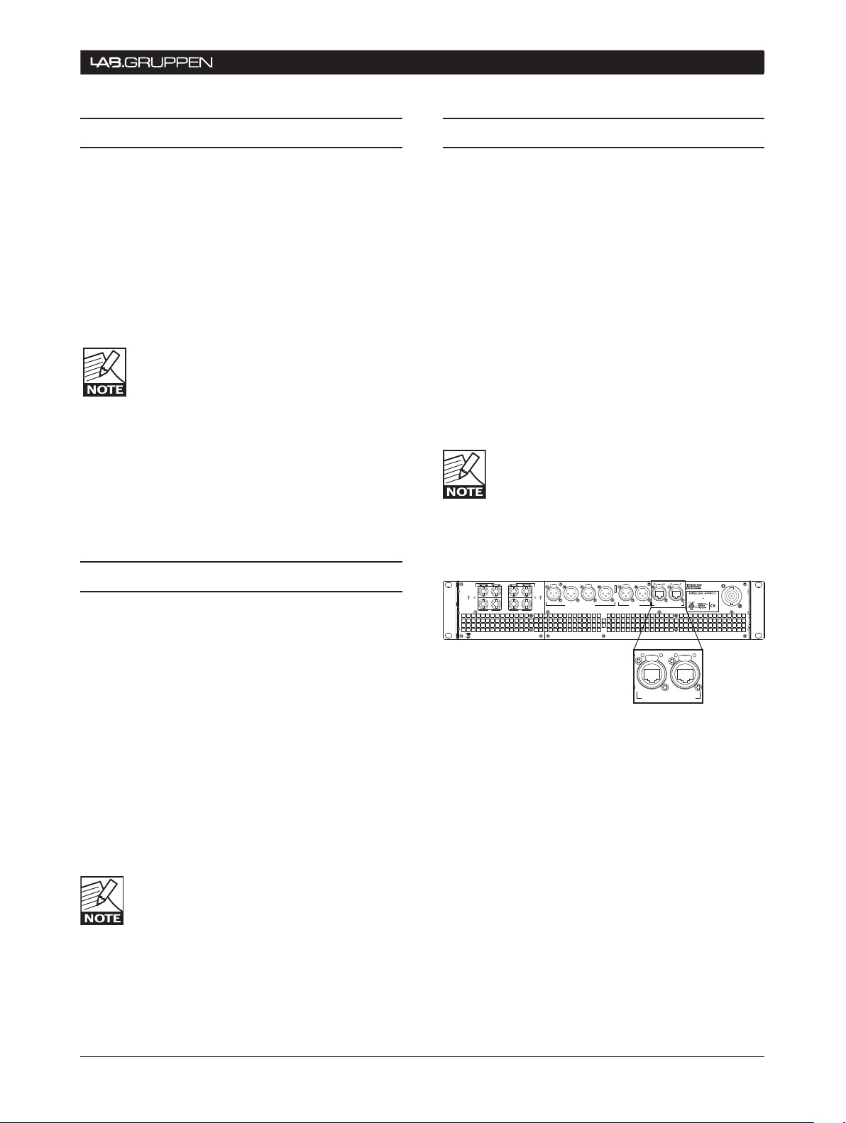
3.3 Rear Panel Connections
The PLM Series has two Ethernet ports for use in
creating free-topology Ethernet-based networking
systems. The ports, located on the back panel (see
figure 1), use Neutrik® EtherCon® RJ45 connectors.
Two LEDs above each port indicate connection to a
valid network (LINK) and the presence of network
activity (ACT).
Both Ethernet ports are 10/100BASE-T with autosensing and auto-uplink. The 10/100 auto-sensing
function automatically configures the Ethernet port
to operate at either 10 MHz (10BASE-T) or 100 MHz
(100BASE-T). The auto-uplink feature automatically
senses the cable type, allowing for either a passthrough (straight) or crossover Ethernet cable to be
used.
Although standard Cat-5 Ethernet cables
can be used to interconnect PLM Series
devices, switches, wireless access points
and routers on the network, Cat-5e Ethernet
cabling is strongly recommended due to its increased
bandwidth capacity.
3.2 Dante Audio Network
The Dolby Lake processor integrated in the PLM
Series incorporates a Dante audio networking interface, allowing the connections to the PLM Series to
be reduced to a single Cat-5e cable which carries all
audio and control information.
Dante, developed by Audinate®, permits the transmission of professional-quality multichannel audio over
an Ethernet network. Dante overcomes the problems
associated with earlier Ethernet-based digital audio
systems, including clock synchronization issues,
lack of true plug-and-play functionality, and channel
count limitations. Additionally, Dante can coexist with
TCP/IP network traffic and other standard control
protocols.
All conductors must be terminated to the
RJ45 connector at both ends of any cable
used for Dante network connectivity.
Figure 3.3: Dual Ethernet ports are located on the PLM rear
panel
Page 6
6 PLM Series Network Configuration Guide
4 avOIDINg SINgLe POINT OF FaILURe (SPF) ISSUeS
Auto input priority switching (managing multiple
4.1 SPF Overview
Critical network configurations (such as those transporting audio signals) should avoid “Single Point
of Failure” (SPF) scenarios to the greatest extent
possible. SPF failures can occur when a network has
been designed in such a way that failure of a single
part of the network can cause the entire network to
fail or cease operation. A network that has not been
designed with the appropriate fail-safe measures
to avoid SPF issues can suffer a breakdown in the
transport of audio and control data, resulting in the
worst case scenario for any professional sound
engineer: dead silence.
The use of redundant network and audio cabling
and switches, as well as the careful selection of the
proper network topology for your application, are
effective tools in avoiding SPF issues.
The PLM Series has been designed with special
features to help prevent this type of system-wide
network breakdown. These include:
•
signal sources)
Support for redundant device sources (e.g. the •
same device providing both analog and AES
sources simultaneously to the network)
Support for redundant network paths (via redun-
•
dant rear panel Ethernet ports on the PLM)
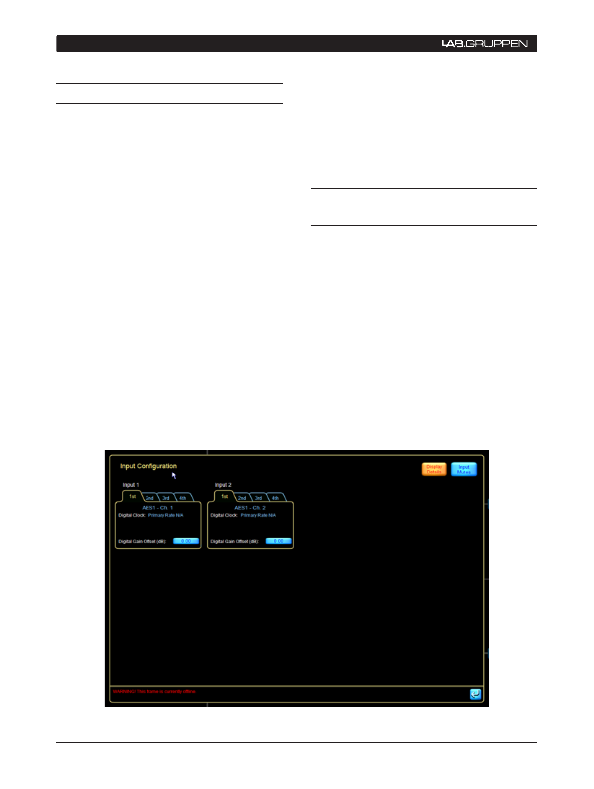
4.2 Automatic Priority Input
Switching
The user-selectable automatic input priority switching
feature in the DLC PLM Edition software is located
on the I/O Config tab of the Input Configuration page
(see figure 4.1). Four levels of input priority are offered, each of which can consist of Analog, AES 1,
AES 2, and Dante. In the event of a loss of signal to
the first priority input, the system will instantly switch
to the next designated priority input and restore audio
connectivity to the system.
Full information on how to select user input priorities
is contained in section 9.12.3.1 of the PLM Series
Operation Manual.
Figure 4.1: Priority input settings are located in the Input Conguration page
Page 7

PLM Series Network Configuration Guide 7
avOIDINg SINgLe POINT OF FaILURe (SPF) ISSUeS 4
4.1.1 Signal type redundancy
Use of this topology allows a PLM to receive audio
and control signals from a source device using different output types, i.e. a device which can output both
analog and AES signals simultaneously. These signals
are then designated as priorities in the auto input
section. Again, please refer to section 9.12.3.1 of
the PLM Series Operation Manual for more detailed
information on setting input priorities.
4.1.2 Signal source redundancy
This priority scheme consists of two sources, in
two locations, acting as prioritized sources in the
same network. Source redundancy also allows the
user to set up two different devices (e.g. PLMs),
feed both with the same input signal (analog or AES
digital), and then have both transfer this signal onto
Dante. Redundant signals are thus transferred to the
network. All PLMs that are required to access this
signal can do so as long as one of the two PLMs
connected to the source device remains on the
network. All remaining PLMs on the network must
be configured to access these same two devices as
the primary and secondary signal sources.
An alternate use of this function is to have
a higher prioritized source as an override.
For example, an AES signal could be dis-
tributed as a fire alarm input that can then
override the normal material distributed via Dante
and/or analog.
4.2 Network Port Redundancy
In this application, the second network port on a
PLM’s rear panel can be configured to be redundant
to the first port. If a parallel network is created, and
the source is connected to both networks, then any
single cable failure or switch failure can be overcome
without any loss of audio signal in the network. It is
also possible to survive multiple hardware failures
with this topography; however, this capability will
depend on the network configuration that is used.
More information about possible configurations is
found in section 5.
Page 8

8 PLM Series Network Configuration Guide
100
100
100 100
100
100
Spectral
Bandwidth Max Length LAN
Cat-5 100 MHz 100 m 100 BASE-T X
Cat-5e 100 MHz 100 m
100 BASE-T X
1000BASE-T
Cat-6 250 MHz 100 m 1000BASE-TX
5 NeTwORk CONNeCTIONS aND TOPOLOgIeS
5.1 PLM Series Network
Cabling
The common cable categories used for high bandwidth network connectivity are Cat-5e and Cat-6;
these are preferred choices for PLM Series network
use. However, Cat-5 may be used in limited applications, as explained below.
Cat-6, as the designation implies, is the newer
standard, and it is designed to accommodate highsp e e d n et works up to 25 0 M Hz . T h e 100 00 B A SE-T X
standard (using 2 pairs) requires Cat-6 cabling. Cat-6 is
fully compatible with all PLM Series network applications (including use with Dante) as it accommodates
all current Ethernet protocols.
Cat-5e (using 4 pairs) supports 1000BASE-T applications, and is also fully suited to all PLM Series
applications, including Dante.
Cat-5 cabling meets the requirements for the PLM
Ethernet control network. However, the higher ratings
of Cat-5e and Cat-6 are recommended for use as the
backbone between switches, particularly if Dante is
being used.
5.2 PLM Series Topology Overview
Than ks to the auto - sense and auto -uplink features of
the PLM Series’ Ethernet ports, connecting multiple
units is a simple task. A free-topology network can
be implemented easily, including external switches
or hubs as required.
Following are some examples of various network
configurations that can be used when setting up a
PLM network.
5.2.1 Daisy-chained devices
If a daisy chain network system (see figure 3) is
implemented, the secondary Ethernet connectors
on PLM Series devices can be used as “loop-thru
outputs” to send the audio and/or control signal to
the next unit in the chain (i.e. in the same rack). As an
example, a system utilizing a Dolby Lake Processor
as a “break in point” would find the DLP typically
connected to the Primary Ethernet port of the first
PLM in the rack. The signal would then travel from
the Secondary Ethernet connector of this PLM Series
unit to the Primary Ethernet connector of the next
unit in the system, and so on.
Cat-3 or Cat-4 cables may still be in use in some
installations. Neither of these satisfies the bandwidth
requirements of 100BASE-TX or 1000BASE-T networking, and should not be used with PLM Series
networks.
Table 5.1 can be used as a guide when specifying
maximum recommended lengths for Ethernet cables
within a PLM network:
Table 5.1: Recommended PLM network cable lengths
Care must be exercised in implementing a
chain topology network, as the number of
PLM Serie s d evices bein g c o nnected in t his
way will have a critical bearing on network
performance parameters such as overall latency.
Also, the use of single layer cabling to connect the
network will introduce the possibility of Single Point
of Failure issues, which should be avoided at all costs
when operating critical systems Therefore, this topology is NOT recommended at all for applications
us ing Dante and it is NOT recommended for applica tions with more than 10 PLMs, even when not using
Dante.
Figure 5.2.1: Daisy chain network topology
Page 9
PLM Series Network Configuration Guide 9
NeTwORk CONNeCTIONS aND TOPOLOgIeS 5
1000 1000
Rack
1000
1000
1000
802.11g/n
100
100
100
Rack
1000
100
100
100
Rack
1000
100
100
100
5.2.2 Star or Hub-and-Spoke networks
An alternative approach is to implement a network
with Star topology, also referred to as ‘hub-andspoke’ or ‘radial’ topology, using a number of Ethernet
switches. (See figure 5.2.2.) In such a network, a
group of PLMs (typically those inside the same rack)
are connected directly to a switch also housed in the
rack. These local switches are then connected to a
“central” switch.
If dual redundancy mode is used, then a completely
parallel secondary network can be created. The
primary network would connect the primary port of
each Dante equipped device (PLM or DLP) and the
secondary network would connect all the secondary
ports.
The dual redundancy mode has the benefit that any
single switch can fail without causing an audible
interruption in the network. However, the control
and monitor PC will have to be manually switched
between the primary and the secondary network if
a failure on one network layer should occur.
A dual redundancy configuration doubles
the number of switches and cables needed.
Also note that the Dolby Lake Processor
(DLP) does not support this redundancy
scheme via dual rear panel Ethernet connectors, so
one DLP per network layer would be required.
5.2.3 Daisy-chained switches
In such a topology, each group of PLM Series units
(typically those inside the same rack) have a switch
inside the rack to which each has a direct connection.
These “local” switches are connected in a daisy chain
(figure 5.2.3). Systems of this type can be made quite
large if the switches are using 1000BASE-T (Gigabit
Ethernet), and although this is a very convenient
system when it comes to wiring, a topology of this
type can potentially develop SPF issues.
5.2.4 Daisy-chained switch ring
This is an enhanced variant of the above that can
be created if the switches support RSTP, or Rapid
Spanning Tree Protocol. (See section 7, References
and Definitions, for more information.) The benefit
of this configuration is that, if there is a cable failure,
the network will recover; all devices on the network
(PLMs, switches, routers, etc.) will still be able to
communicate. If a switch fails, all devices will remain
connected to the network, with the exception of
those devices that are directly connected to the failed
switch. If Dante is being used, there will be a brief
audible interruption in the sound (5 ms – 2 s), the
length of which will depend on the size of the system
and the vendor of the switch.
The PLM’s own internal switches do not
support RSTP. Care must be taken to not
create a ring (closed loop) with the PLM’s
rear panel connectors.
Figure 5.2.2: Two level star topology
Page 10

10 PLM Series Network Configuration Guide
1000
Rack
1000 1000
1000
100
100
100
1000
Rack
1000
100
100
100
1000
Rack
1000
100
100
100
1000
Rack
1000 1000
1000
100
100
100
1000
100
100
100
1000 1000 1000
Rack
1000 1000
100
100
100
1000
100
100
100
1000 1000 1000
Rack
1000
100
100
100
1000
100
100
100
1000 1000
5 NeTwORk CONNeCTIONS aND TOPOLOgIeS
Figure 5.2.3: Daisy chained switches
Figure 5.2.5: Dual daisy chain switch topology
5.2.5 Dual daisy-chained switches
This is a hybrid that combines the ease of wiring
of the daisy chain topology with the 100% avoidance of SPF issues in the dual redundant star/spoke
configuration (figure 5.2.5). It is simply two “daisy
chained switch” networks in parallel: the primary and
secondary networks are connected independently
using the dual redundant mode in the PLMs.
If the control computer only has one network
card, it can be connected to only one of the
network layers. The solution to this situation
can be as follows:
Manually disconnect from the “blue“ network •
layer and connect to the “red” network layer
instead if one or more PLMs are inaccessible via
the blue network (see figure 5.2.5). This can be
done easily by using a simple hardware switch
box.
A more advanced solution would be to equip
•
the PC with two identical network cards and
appropriate drivers so that it can be connected
to both networks simultaneously.
may be to place a group of local switches in each
“zon e”, which are fi r s t interc onnected to form a “l o c al
area network” (e.g. Stage Left). These area networks
are then interconnected with a main backbone. A
different topology for the main backbone than that
of the local area network may be chosen, depending
on your specific application and resources.
Figure 5.2.6 shows an example of a combined network utilizing both Star and Daisy Chained switch
ring topologies.
5.3 Ethernet Cabling Limitations
The maximum cable length allowed between any
two devices on a net wo rk is defined by the Ethe r n et
protocol and is limited to 100 meters (330 feet) for
copper connections. The term “devices” includes:
The host PC running the Dolby Lake Controller •
PLM Edition software
Any switch on the network•
Any access point•
Any PLM•
5.2.6 Other combination networks
In larger system network topologies, a good solution
Optical fiber can be used if longer distances are
needed. Multi-mode fiber supports up to 550 meters
(1800 feet) and single mode supports even longer
Page 11

PLM Series Network Configuration Guide 11
Rack
1000 1000
100
100
100
1000
Rack
1000
100
100
100
1000
1000
Stage Right
1000
Rack
1000
100
100
100
1000
Rack
1000
100
100
100
1000
1000
Stage Left
FoH
1000
1000
1000
1000
Link speed [Mbps]
System type 1* 2**
Source 100 100
Backbone 100 1000
Sink 100 100
Network diameter
[# of “hops”]
14 62
Latency setting 1 0.8 ms 1 4
1 1
2 9
Latency setting 1 1.3 ms 4 19
14 >20
56 256
Latency setting 2 4.0 ms 9 45
7 34
* PLM/DLP without external switches or with 100 Mbps switches
(not a recommended setup!)
** Recommended PLM only example with Gigabit switch backbone
NeTwORk CONNeCTIONS aND TOPOLOgIeS 5
distances. The recommended LinkSys switch can be
upgraded with SFP modules to support fiber connections (See section 7, References and Definitions,
for more information on SFP.)
Table 5.4: PLM network diameter guide
Figure 5.2.6: Combined network topology
5.4 PLM / Dante Network Size
The information below is provided to give an overview
of the terminology and concepts that are used when
describing a PLM network and its functions. Further
explanations of terminology used can be found in
section 7, References and Definitions.
A cable connection from one network port to another
is often referred to as a hop.
The maximum size of a network is often referred to as
the network diameter. The optimal network diameter
is defined by the time it takes for a packet to get from
one device to another across the furthest point in the
network, in terms of communication time.
Most of the time consumed in the path, generally
referred to as latency, is the hardware reaction
and transmission time. The time consumed for the
packets to travel over the network Ethernet cables
themselves is very small in comparison. If we assume
100 m copper cables for all hops, we can present
some simple rules for how many hops are permitted
from any Dante source device to any of its recieving
Limitations
Page 12

12 PLM Series Network Configuration Guide
5 NeTwORk CONNeCTIONS aND TOPOLOgIeS
devices (or sinks) for a given latency setting. Table
5.4 shows the limits for a Dante system with PLM
Series devices as the sinks.
The recommended system is shown in grey in Table
5.4. It has a DLP or PLM as the source (100 Mbps)
and PLM Series devices as sinks. The first and last
hops are 100 Mbps; all other hops, including those
between switches, are 1000 Mbps.
If the latency is assumed to be 1.3 ms we can have
34 hops from the source devices to any PLM. If we
assume 3 x PLMs per rack in any variant of the daisy
chained switch topologies (ring or dual chain), we
could then support a system with 33 racks, giving
99 PLMs (396 channels).
If the topology is layered or star/spoke, the system
could be even larger. The DLC PLM Edition software
us er inte r fa c e is designed to display 125 PLM Serie s
devices on an XGA screen.
A system of this size has been assembled
and verified by Lab.gruppen engineering at
our factory location.
for use in larger venues; however local legal restrictions
may apply in some countries. Please contact your Lab.
gruppen distributor for advice if necessary.
5.6 Improving Wireless Accessibility
Primary and Secondary PC
In a p p lications whe re maint a ining cont rol and moni toring throughout the event is critical, and yet where
mobile control access is also desired, users should
have a primary control PC connected via wire in
conjunction with a wireless secondary PC.
Multiple access points, single SSID
Two or more access points can be connected to the
same network as long as they are given the same
SSID, the name used to identify a particular LAN within
range of a PC. (See section 7 References and Definitions for more information.) The user can then move
freely around the venue and maintain connection to
the network via the closest access point.
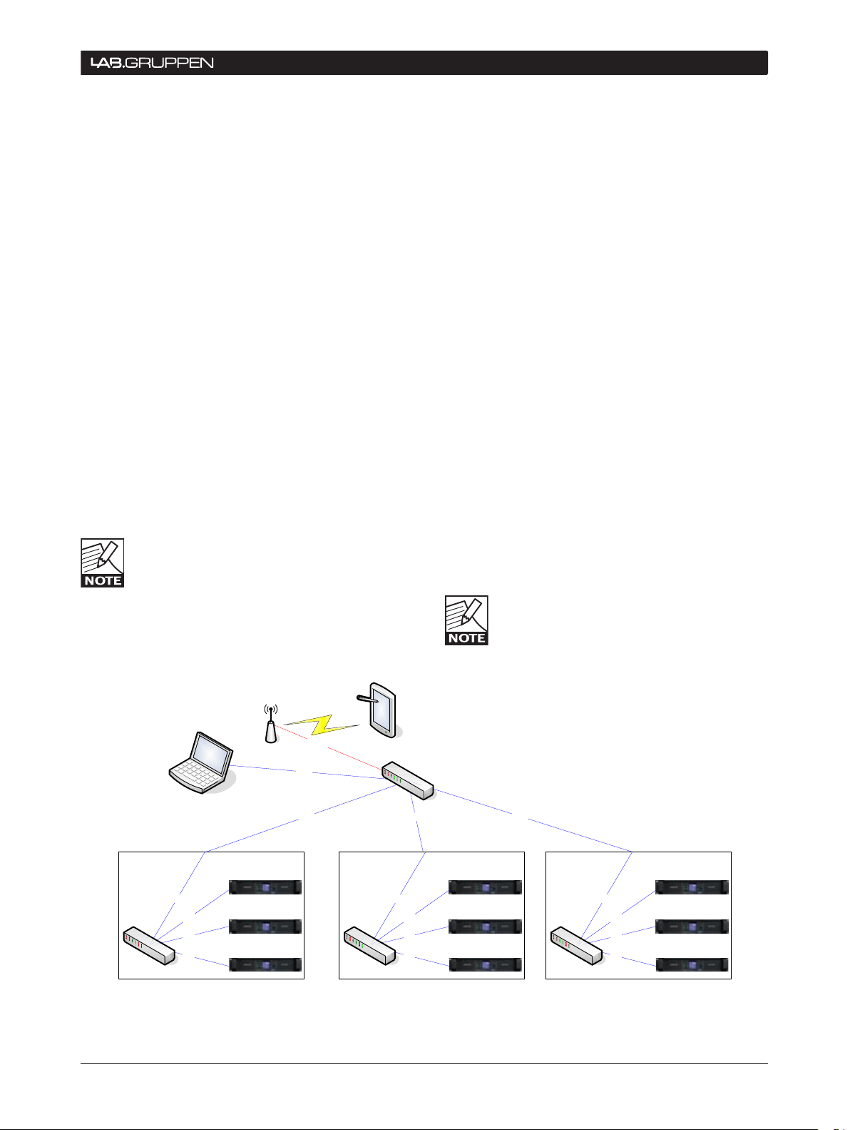
5.5 Wireless Network Topologies
Adding wireless networking to the system provides
portable, centralized control to a distributed network
of PLM Series devices (as well as other Dolby Lake
processors.) A wireless network greatly enhances
the flexibility of control of a large audio system, as
the control location is not fixed. A wireless access
point simply works as a gateway between the wired
network and wireless devices. A Tablet PC running
the Dolby Lake Controller PLM Edition software then
communicates with the access point wirelessly, allowing control of the system from anywhere in the
venue that is within wireless range
Wireless connections are generally slower
than wired connections, and can result in
varying degrees of Ethernet performance.
Connection quality can depend on the
distance and angle to the access point as well as the
presence of any surrounding interference. Strong
interference may lead to loss of connection.
5.7 Using Dante in Conjunction with Wireless Networks and Low Bandwidth Devices
For Dante to operate on a network link, the network
has to provide a bandwidth of at least 100 Mbit/s.
Hence Dante does not operate over wireless links.
In order to attach a wireless accesspoint to a Dante
enabled network, special attention needs to be taken
to make sure the Dante packets do not flood the wireless link. A switch that is configured to filter out the
Dante packets must be installed at the boundary of
the wireless network.
Dolby Lake legacy products such as Contour and Mesa
Processors are 10 MBit/s devices. If these devices
are to be connected to a Dante enabled network, the
same type of filtering of Dante packets is necessary.
Please refer to the Audinate document “AUD-ANOACL_Filtering_SRW224G4 -V2.4.pdf” for further details
regarding filtering of Dante packets.
Booster antennae are highly recommended
Page 13

PLM Series Network Configuration Guide 13
NeTwORk HaRDwaRe ReCOMMeNDaTIONS 6
6.1 General Recommendations
Critical networks such as those used in professional audio systems require infrastructure hardware
offering the high level of connectivity and reliability
essential for critical, data-intensive applications.
Additionally, this hardware needs to be robust enough
to survive the rigors of repetitive loading and unloading, and frequent connection and disconnection.
Lab.gruppen has evaluated a number of hardware
manufacturers in regard to use within a PLM Series
network. Our findings have resulted in the following
hardware recommendations. Of course, there are any
number of scenarios involving systems of various
sizes, logistical and routing requirements, so these
recommendations are to be considered as guidelines
only.
In addition to the recommendations provided, other
products may be equally suited to PLM Series applications. Lab.gruppen will continue to evaluate and
verify network products as the market for network
devices changes rapidly. Updated information will be
posted at www.labgruppen.com/plm.
6.1.1 Network switches / routers: LinkSys SRW224G4
Depending on the configuration selected, the
appropriate network switch or router will have enough
ports to accommodate direct connection to each PLM
in the rack as well as connections from rack to rack
where required in the system-wide configuration.
Switches manufactured for mounting into a standard
19 inch equipment rack are generally considered
more appropriate to withstand the rigors of loading
and unloading that can be part of a sound system’s
daily use.
In systems that DO NOT utilize Dante, Lab.gruppen
is not providing a specific recommendation. In general, however, a switch with RSTP is recommended.
This greatly increases reliability in case of any loss of
information or connection failures. It is also a good
practice to use switches that allow monitoring of
links over the network.
In systems where Dante is used, the switch should
have 1000BASE-T (or better) for switch-to-switch
connections. The switch must support the DiffServe
Code Point (DSCP) protocol, and it must implement
strict priority control over at least the top two priority
levels. (3Com is an example of a provider that typically prioritizes only the top level.) See References
and Definitions in section 7 for more on DSCP.
Internal switch forwarding latency of 4 µs or less is
recommended.
Several switches have been tested by
Lab.gruppen and not all behave according
to their datasheets. Some others that
comply with general specifications have a
tendency to drop packets, and therefore cannot be
recommended.
LinkSys SRW224G4
19 inch rack-mountable•
24 x 10/100 switched RJ4 5 ports•
4 x 10/100/1000 switched RJ45 ports•
2-SFP slots for use with fiber optic connections•
RSTP supported•
Secure remote monitoring software available (freeware) •
Approved by Audinate, developers of the Dante network•
Manufacturers link: www.linksys.com•
6.1.2 Recommended wireless access point:
LinkSys WAP200
Access points utilizing the 802.11g or 802.11n
formats are recommended both for their diversity
and bandwidth. A PoE-type (Power over Ethernet /
802.3af) access point that can be powered over its
Ethernet connection is also a good idea, as it is very
easy to place at an optimal location since only one
cable is needed for both network connectivity and
power. (See in section 7 References and Definitions
for more information.)
If the switch doesn’t have PoE, then a mid-
span PoE adapter is needed as well.
Page 14

14 PLM Series Network Configuration Guide
6 NeTwORk HaRDwaRe ReCOMMeNDaTIONS
LinkSys WAP200
802.3af compatible•
256 bit secure encryption•
Ra ngeB ooste r™ t echno logy i ncr eas es r ang e an d de cre ase s
•
dead spots using standard antennae
Good results even with obstructive objects in broadcast
•
path
Accepts standards-based PoE (IEEE 8 02.3af) or external
•
DC power
Manufacturer website: •
www.linksys.com or www.3com.com
6.1.3 Recommended network cabling: Belden 1305A
Although Belden 1305A is a stranded-type
cable providing high resilience against failure
from repetitive bending or stressing, it ex-
hibits a loss of 26.4 dB instead of the 24
dB that is stated in the Cat-5e requirements. This
limits the recommended length to 90.9 m. Please
be aware that Lab.gruppen has not verified performance at the maximum length.
Belden 1305A Cat-6 cable
only guarantees the performance of the EtherCon
for 1000 mating cycles.
In order to provide a more reliable long-term solution, Lab.gruppen recommends the circular metal
push-pull connector from LEMO®. These connectors
are rated to withstand 5000 mating cycles, and are
available in both crimped and soldered versions.
LEMO connectors
Rated at 5000 insertions•
Operational from -50 C to + 200 C•
Nickel / brass construction•
Manufacturer website: www.lemo.com•
Recommended part numbers: •
Female panel connector• PEG.2K.308.CYMC75
Male cable connector• FGG.2K.308.CYCC75Z
Female panel connector • PHG.2K.308.CYMC75Z
In order to use the LEMO connector one
must use the following pin out. Pins 4 and
6 are “shifted”. If the connector is made
with a pin-to-pin wiring configuration, the
connection will work for 100BASE-TX, but not for
10 00 B ASE-T.
4 pair / 8 conductor•
Wire pairs are glued together to resist bend failure•
Approved for both indoor and outdoor applications•
Operating temperature of -20 C to +60 C•
Manufacturer website: www.belden.com•
6.1.4 Recommended network connectors: LEMO-type multipin connector
The Neutrik EtherConRJ45 connector has come into
wide use in the touring business. However, Neutrik
RJ-45 LEMO
1 1 orange/white
2 2 orange
3 3 green/white
4 6 blue
5 5 blue/white
6 4 green
7 7 brown/white
8 8 brown
Page 15

PLM Series Network Configuration Guide 15
REFERENCEs AND DEFINITIONs 7
The following definitions will help the user better understand some specific terms used in this guide, and in other
PLM Series technical documentation. Lab.gruppen has made every effort to make sure that the information here
is correct and accurate.
Ter m Description
Auto-sensing
Auto-uplink
Backbone
Crossed network
cable
Differentiated
Services Code Point
(DSCP)
Dual-net work
topology
Hop
Latency
MAC address
Packet
Power over Ethernet
(PoE)
Rapid Spanning Tree
Protocol (RSTP)
SFP (Small Formfactor Pluggable)
SSID
Star
Switch (Ethernet)
.
The Ethernet port s on the PLM autom atical ly determine the base speed of the networ k connect ion (10Bas e-T or 100 Base -T) and co nfigure
themsel ves appropriate ly.
The Et hernet por ts on the PLM are ab le to operate wit h either st raight or cross ed net work cabl es. T his a bilit y to c onnec t cor rectly with
either t ype is termed auto -uplinking .
Large Ethernet netwo rks are of ten imp lemente d with a very h igh speed “tru nk” part of the network topology feeding the mai n switch es,
which in tu rn supp ort sm aller, lower- spee d local networ ks. The te rm back bone is used to desc ribe such a trunk .
An Ethernet cable in whic h four of the eight conductors (pin s 1, 2, 5 & 6) are not wired pin- to- pin. Suc h a cable is require d in convention al IT
networ ks to conne ct two P Cs toget her with out usin g a hub or switch. The auto- uplin k feature of th e PLM’s Ethernet p orts allows cros sed
cables to be used if w ished . See also S traight n etwor k cable.
DSCP is a network ing archite cture that spec ifies a simple, scalable mechanism for clas sify ing and managing netw ork traf fic to provide
Qualit y of Servi ce (QoS ) guarantees on IP networks . DSCP can be used to provide low- latency, guarantee d servic e to critical tr affic suc h as
audio or v ideo, wh ile provi ding best effor t traf fic guar antees to no n- critical ser vices s uch as control or st atus infor mation .
A networ k topol ogy consisting of two (usually) identical networks, one co nnecti ng to the Primary Ethernet por ts and the other to the
Secon dary por ts. Alt hough more complex to implement , the advantag e of using a dual-net work syste m is one of greatly improved reliab ility
as one com plete net work rem ains ope ration al if the oth er should fail.
A cable c onnect ion from o ne netwo rk por t to the next n etwor k port .
The small but finite delay incur red by audio signals when they are trans formed into the di gital domain, processe d digitally, and t hen
conver ted back i nto analo g signals. In the Do lby Lake s ystem, la tency is assured to be c onsta nt.
In addition to an IP address, ever y devic e on an Ethernet net work has a MAC add ress. This address is fixed at the tim e of manufact ure, and
is effectively th e perma nent identifier of t he physical unit . MAC stands for Media Ac cess Co ntrol
A packet is a formatte d block of data co nsisting of both control da ta and user data, also known as the pa yload . Control informatio n provides
data nee ded by the ne twork to d eliver the user data (paylo ad) and as sure dat a integrit y. Each pa cket travel s over the net work as a dis crete
and uninterrupted b lock of d ata.
Power over Ethern et is a sy stem for t ransmitting e lectr ical p ower over a twis ted pai r cabl e along with th e data . It is fu nctionally similar to
the phanto m poweri ng of micro phones over audio c ables . PoE allows poweri ng of remote network s witches a nd other applian ces with out
the need of a s eparate power sup ply and A C mains wiring.
RSTP is a data com munica tion protoc ol that enabl es fast restorat ion of servi ce following failure or interruptions on a netwo rk link. Base d on
the old Sp anning Tree Protocol, i t retains t he plug -an d- play ben efits wh ile provi ding far f aster rec overy of n etwork connec tivit y.
SFP is an optical transce iver used in data communic ations. It interfaces a network device to a fi ber optic cabl e, allowing the networ k to carry
large amounts of da ta over lon g distances wit h minimal l atency.
A Ser vice Set Identi fier, or SSI D, is used to identify the part icular 80 2.11 wireless LA N to which a us er wis hes to att ach. A clie nt dev ice
receives mes sages from all access points wit hin r ange. Selection of the ac cess point can be pre- configured within the client device , or
chosen by a u ser from a displaye d list of SS IDs. M ultipl e acces s points w ill have th e same SS ID if they provide a ccess of the same L AN.
A network topol ogy which uses a network switch to connec t to individual PL Ms. Each PLM con nects to one port on the switch wit h its own
cable; th us the net work looks like a star when drawn as a diagram wit h the switc h at the cent re.
An Ethernet switch allow s sever al Eth ernet device s to b e connected to a netwo rk using a star topology. More inte lligent than the e arlier
hubs (whic h they now largely repl ace) , switches route pac kets of data only to the units for which they are inten ded, and also per form other
system hou sekeepi ng and con trol func tions.
Page 16

8 ADDITIONAl INFORmATION
Contact:
Lab.gruppen AB
Faktorvägen 1
SE-434 37 Kungsbacka
SWEDEN
Phone: +46 300 56 28 00
Fax: +46 300 56 28 99
plmsupport@labgruppen.com
info@labgruppen.com
www.labgruppen.com
Intercooler and Class TD are national and/or
international registered trademarks of Lab.gruppen AB.
PLM, Powered Loudspeaker Management, R.SMPS,
LoadLibrary, LoadSmart, SpeakerSafe and ISVPL are
trademarks of Lab.gruppen AB.
Dolby, Lake, and the double-D symbol are registered
trademarks of Dolby Laboratories. Dolby Lake Processor,
Lake Contour, Lake Mesa Quad EQ, LimiterMax and
Iso-Float are trademarks of Dolby Laboratories.
All other trademarks remain the property of their
respective owners.
Copyright © 2008 Lab.gruppen AB. All rights reserved.
16 PLM Series Network Configuration Guide
Page 17

Lab .gruppe n ab • Sweden
internationaL contact • info@La bgruppen.co m
uS contact • infouS@tceLectronic.com
www.labgr uppen.com
 Loading...