

Page 1

Overview
Hardware Installation
IWILL DK8X Motherboard
User’s Manual
BIOS Setup
DK8X Version 1.1
Page 2

DK8X Motherboard
________________________________________________________________
ii User’s Manual
Page 3

FCC Compliance Statement
This equipment has been tested and found to comply with limits for a Class B digital device,
pursuant to Part 15 of the FCC rules. These limits are designed to provide reasonable protection
against harmful interference in residential installations. This equipment generates, uses, and can
radiate radio frequency energy, and if not installed and used in accordance with the instructions,
may cause harmful interference to radio communications. However, there is no guarantee that
interference will not occur in a particular installation. If this equipment does cause interference to
radio or television equipment reception, which can be determined by turning the equipment off
and on, the user is encouraged to try to correct the interference by one or more of the following
measures:
1. Reorient or relocate the receiving antenna
2. Move the equipment away from the receiver
3. Plug the equipment into an outlet on a circuit different from that to which the receiver is
connected
4. Consult the dealer or an experienced radio/television technician for additional suggestions
You are cautioned that any change or modifications to the equipment not expressly approve by
the party responsible for compliance could void Your authority to operate such equipment.
This device complies with Part 15 of the FCC Rules. Operation is subjected to the following two
conditions
1. This device may not cause harmful interference
2. This device must accept any interference received, including interference that may cause
undesired operation.
User’s Manual iii
Page 4

DK8X Motherboard
Disclaimer
The information in this document is subject to change without notice. The manufacturer makes no
representations or warranties regarding the contents of this manual and specifically disclaims any
implied warranties of merchantability or fitness for any particular purpose. Furthermore, the
manufacturer reserves the right to revise this publication or make changes in the specifications of
the product described within it at any time without notice and without obligation to notify any
person of such revision or change.
Trademarks
Microsoft and Windows are registered trademarks of Microsoft Corp. Intel and Pentium 4 are
registered trademarks of Intel Corporation. Other product names used in this manual are the
properties of their respective owners and are acknowledged.
Copyright
This publication, including all photographs, illustrations and software, is protected under
international copyright laws, with all rights reserved. Neither this manual, nor any of the material
contained herein, may be reproduced without the express written consent of the manufacturer.
IWILL ©Copyright 2003
iv User’s Manual
Page 5

Table of Contents
1: Overview ....................................………………………................. 1-1
Workstation Board Specification .....................................………………………...... 1-5
Mainboard Map ...................................................………………………......... 1-7
I/O Port Array …………………………………………………………………………… 1-8
2: Hardware Installation ...................................……………………... 2-1
Map of Jumpers ...............................................................……....………………….. 2-2
CN32: Clear CMOS Header ................................……....……....…………….......... 2-3
CN21: PCI 64 Bit Slot Speed Select Jumper ………...........…...……....……2-4
CN25: PCI-X Slot Speed Select Jumper …........………………………..... 2-4
J11: Audio for Front Panel …………….….………………………..…. 2-5
JP1: IEEE-1394 Enable/Disable ................................………………………........ 2-5
CN49: Chassis Intrusion Header ................................………………………........ 2-6
Memory Installation Procedure …………..…………………………..………………2-8
Installing the Processor and Heatsink ............…………………………....…….2-11
AGP Pro Slot ..............………..............................………………………......... 2-13
EPS12V Power Connectors …………….....................………………………........ 2-14
FDD Connectors ..........................................………………………......... 2-15
IDE_P, IDE_S: IDE Drive Connectors.......................………………………....... 2-15
Front Panel Switches ...................................................…………………………... 2-16
System Fan Connectors…………….....................……………………………….... 2-18
Rear Panel I/O Ports…………….....................……………………………….... 2-19
Additional I/O Connectors………….....................……………………………….... 2-21
Installing Expansion Cards………….....................……………………………….... 2-23
Silicon Image Chipset and Serial ATA…..............……………………………….... 2-24
_____________________________________________________________________
User’s Manual v
Page 6

DK8X Motherboard
3: BIOS Setup ..............................................………………………........... 3-1
Starting the BIOS Setup .....................................……………………..……..3-1
Using the BIOS Setup Utility.........................…................................................. 3-2
Main Menu ......................................………………………..…......... 3-4
Advanced Menu ...............................…………………………................. 3-6
IDE Configuration Submenu .....................…………………………........................ 3-7
Super IO Configuration Submenu..........…………………………........................ 3-8
PCIPnP Menu ...……………….........…………………………..................... 3-9
Boot Menu ...............................…………………………..................... 3-12
Boot Setting Configuration Submenu .......………………………......................... 3-13
Security Menu....................................…………………….......…….... 3-15
Chipset Menu…….....................................................….... 3-16
NorthBridge Configuration Submenu.....………………………….......... 3-16
SouthBridge Configuration Submenu .................…………………………..... 3-19
AGP Configuration Submenu .......................................…………………………... 3-20
APM Configuration Menu .....................................…………………………. 3-21
Exit Menu ………………………………………………………………..……….3-22
________________________________________________________________________
vi User’s Manual
Page 7

Chapter 1 Overview
Overview
Thank you for choosing this high performance motherboard. This is a dual AMD Opteron
micro-Socket 940 motherboard (M/B) based on the EATX form factor and features the
AMD® HyperTransport™ I/O Hub (8111) AMD HyperTransport PCI-X Tunnel chipset
(8131) and the AMD® AGP Tunnel (8151) chipset. The board features a Hyper Transport
bandwidth of 6.4 GB/s.
For memory options, there are eight (8) sockets to support up to 16 GB of memory using
184-pin Registered PC3200/PC2700/2100 ECC DDR memory modules.
Flexibility and expandability are provided by two 32-bit/33Mhz PCI slots, one
64-bit/66MHz PCI slot, two PCI-X slots and an AGP Pro/ 8X slot. This selection of PCI
slots permits the use of numerous add-on cards and Peer PCI transaction support provides
increased system performance.
Other features include an onboard Silicon Image® Serial ATA interfaces, a 3COM®
Gigabit Ethernet controller, an onboard RealTek® ALC-655™ audio chip, and USB 2.0
to provide high system capabilities that meet a wide range of demanding applications.
Before we begin the manual, we would like to go over some precautions to insure the
safety of both the Mainboard and the technician/operator. Please read the General Safety,
ESD, and Operating Precautions in their entirety before beginning.
________________________________________________________________________
Overview 1-1
Page 8

DK8X Motherboard
GENERAL SAFETY PRECAUTIONS
Keep the area around the Server clean and free of clutter.
Servers weigh a lot. They can average about 50 lbs. (~22.68 kg)
When lifting the system, two people should lift slowly from opposite ends with their
feet spread out to distribute the weight. Always keep your back straight and lift with
your legs.
Place the chassis top cover and any system components that have been removed
away from the system or on a table so that they won¡¦t accidentally be stepped on.
While working on the system, do not wear loose items such as neckties and
unbuttoned shirt sleeves. They can come into contact with electrical circuits or get
pulled into a cooling fan.
Remove any jewelry or metal objects from your body, which are excellent metal
conductors and can create short circuits and harm you if they come into contact with
printed circuit boards or areas where power is present.
ESD
PRECAUTIONS
Electrostatic discharge (ESD) is generated by two objects with different electrical charges
coming into contact with each other. An electrical discharge is created to neutralize this
difference, which can damage electronic components and printed circuit boards. The
following measures are generally sufficient to neutralize this difference before contact is
made to protect your equipment from ESD:
Use a grounded wrist strap designed to prevent static discharge.
Keep all components and printed circuit boards (PCBs) in their antistatic bags until ready
for use.
________________________________________________________________________
1-2 Overview
Page 9

Chapter 1 Overview
Touch a grounded metal object before removing the board from the antistatic bag.
Do not let components or PCBs come into contact with your clothing, which may
retain a charge even if you are wearing a wrist strap.
Handle a board by its edges only; do not touch its components, peripheral chips,
memory modules or contacts.
When handling chips or modules, avoid touching their pins.
Put the motherboard and peripherals back into their antistatic bags when not in use.
For grounding purposes, make sure your computer chassis provides excellent
conductivity between the power supply, the case, the mounting fasteners and the
motherboard.
After accessing the inside of the system, close the system back up and secure it to
the rack unit with the retention screws after ensuring that all connections have been
made.
O
PERATING PRECAUTIONS
Care must be taken to insure that the chassis cover is in place when the server is
operating to assure proper cooling.
Out of warranty
damage to the server can occur if
this practice is not strictly followed.
____________________________________________________________________________________________________________
Overview 1-3
Page 10

DK8X Motherboard
G
ETTING HELP
If a problem arises with yours system during Installation or Operation, you should first
ask your dealer for help as they have most likely configured your system. They generally
have the best grasp of your issues and the fastest response for your symptoms. If your
dealer is near your location, it is recommended that you first bring your system to them to
have it serviced instead of attempting to solve the problem yourself.
If those options don't work for you, IWILL also provides some helpful resources to help
you.
1. Visit IWILL® website at www.iwill.net and navigate to this product’s page which
contain links to product updates such as Jumper settings or BIOS updates.
2. The FAQ (Frequently Asked Questions) sections in the IWILL website are often
helpful since other users often have the same questions.
3. Email us at: support@iwill.net and we will try to answer your questions within 5
business days.
1-4 Overview
Page 11

Chapter 1 Overview
WORKSTATION BOARD SPECIFICATIONS
Processor 1. AMD® Dual Opteron Socket 940 CPUs
2. Supports 1.8 GHz or higher
3. HyperTransport™ of 6.4 GB/s bandwidth
4. Built-In Memory Controller Hub (MCH)
Chipset 1. AMD® 8111 (HyperTransport I/O Hub)
2. AMD® 8151 (AGP Tunnel)
3. AMD® 8131 (PCI-X Tunnel)
Memory 1. 4 + 4 socket for 184-pin DDR DIMM sockets
2. Uses Registered PC3200/PC2700/PC2100 ECC DDR
memory
3. Supports total system memory size of up to 16 GB
Internal I/O connector 1. 34-pin Floppy Connector
2. 4-pin CD-In and Aux-In audio input connectors
Accelerated Graphics
Port
IDE Bus
On-Board LAN Integrated single 3com 3C940 Gigabit Ethernet Controller
Audio
USB Integrated NEC with four (4) USB 2.0 ports
Expansion Slots
AGP Pro/ 8X/4X slot
1. 2x 40-pin IDE connectors, supports up to four (4) Enhanced
IDE devices
2. Dual Channel Master Mode
3. Ultra DMA 133/100/66/33
1. Integrated Realtek® ALC-655, Professional 6-channel Audio
2. AC '97 CODEC
2 x internal USB1.1 ports
1. 2x PCI 32-bit / 33 MHz
2. 1x PCI 64-bit / 66 MHz
3. 2x PCI-X 100/133 MHz
PS/2 mouse and keyboard connectors with Wake-Up function
1 x UART 16550 serial port (COM1)
Rear Panel I/O
1 x 25-pin parallel port with ECP/EPP support
2 x onboard USB 1.1 ports
4 x USB 2.0 ports (2 x external, 2 x internal)
Page 12

1 x GigaBit Ethernet LAN RJ-45 port
Audio Phone Jacks - Speaker Out, Mic In, Line-In.
1x IEEE-1394 port
Center Out, Rear Out
System Management
System BIOS
Form Factor
Serial ATA
IEEE 1394
Hardware Monitor (CPU Thermal, Fan, Voltage, Intrusion)
WINBOND W83627THF
4Mb Flash EEPROM with AMI BIOS
I2C support. SMBIOS 2.3 and DMI 2.0 compliant
Soft Power-Down
Secure Boot, Multiple Boot support
Extended ATX form factor
EPS 12V power connectors (24 pin + 8 pin)
Silicon® Image Sil3114 chipset
4 Serial ATA ports with RAID 0, 1 and 10
Integrated TI® TSB43AB22 for IEEE 1394 port
(1x onboard, 1x header)
________________________________________________________________________
1-6 Overview
Page 13
Chapter 1 Overview
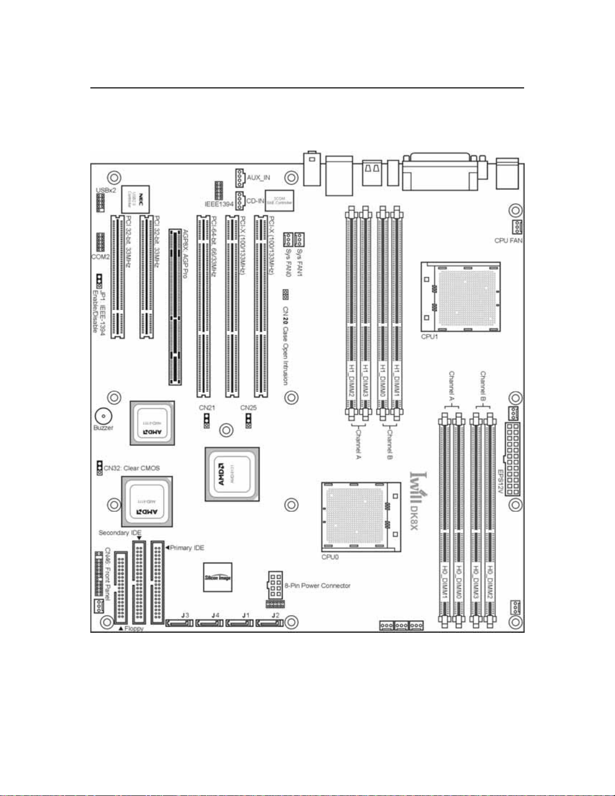
MAINBOARD MAP
____________________________________________________________________________________________________________
Overview 1-7
Page 14
DK8X Motherboard
REAR I/O ARRAY
________________________________________________________________________
1-8 Overview
Page 15

Chapter 2 Hardware Installation
Hardware Installation
In this section, we detail the procedures for how to install processors and other hardware
components in your Mainboard. Please go to the specific sections to read more about
section you are interested
¾ WARNING
This motherboard contains sensitive electronic components that can be easily damaged
by static electricity. Follow the instructions carefully to ensure correct Installation and to
avoid static damage.
________________________________________________________________________
Hardware Installation 2-1
Page 16
DK8X Motherboard
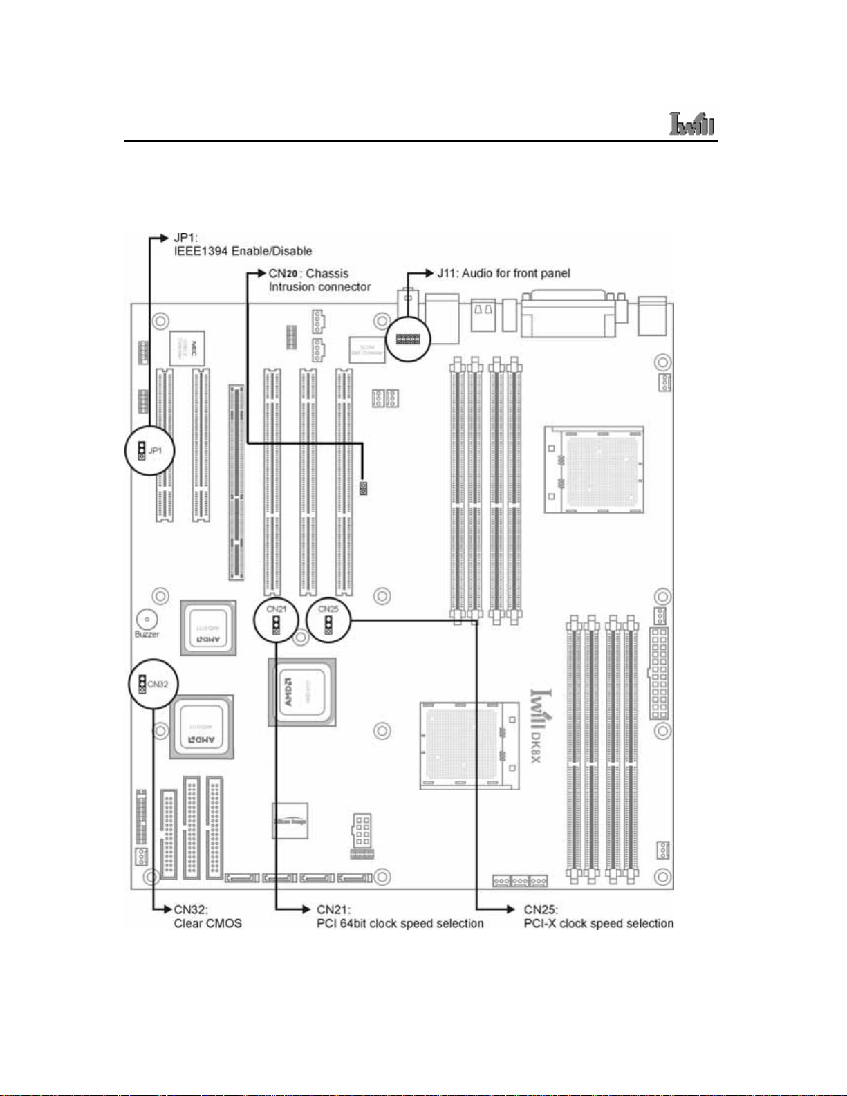
MAP OF JUMPERS
Refer to the following illustration to find the location of the Mainboard's jumpers
________________________________________________________________________
2-2 Hardware Installation
Page 17

Chapter 2 Hardware Installation
CN32: Clear CMOS Header
The onboard button cell battery powers the CMOS RAM. It contains all the BIOS setup
information. Keep the jumper connected to pins 1-2 (Default) to retain the RTC data as
shown below.
1
2
3
1-2 2-3
Normal (Default) Clear CMOS
Under certain circumstances, you will need to reset system settings. Follow these
instructions to clear the CMOS RTC data:
1. Turn off the computer.
2. Short pins 2 and 3 with a jumper for a few seconds.
3. Replace the jumper to pins 1 and 2.
4. Turn on your computer by pressing the power-on button.
5. Hold down <F2> during boot and select either <Load Optimal Defaults> or
<Load Failsafe Defaults> in the “Exit” section. Then go through the BIOS setup
to re-enter user preferences. Refer to Chapter 2 BIOS SETUP for more
information.
________________________________________________________________________
Hardware Installation 2-3
Page 18
DK8X Motherboard
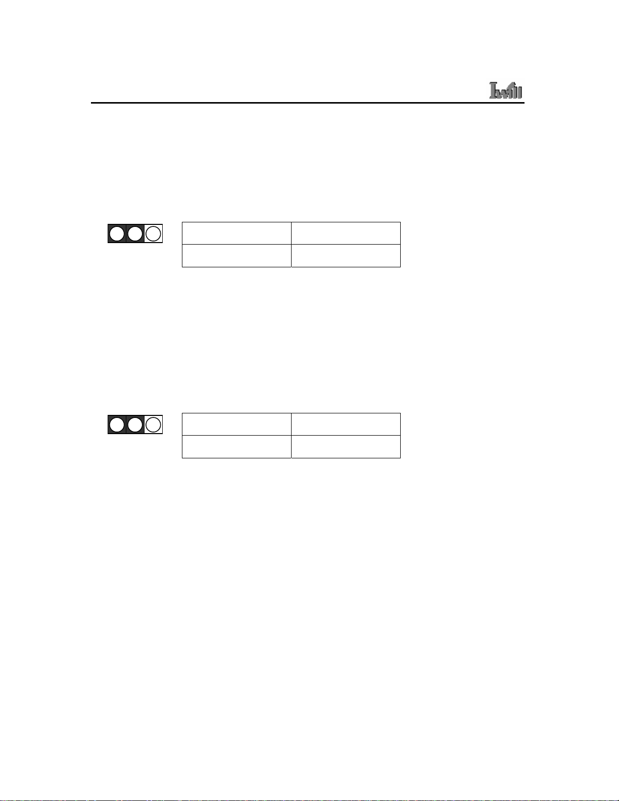
CN21: PCI 64-Bit Speed Select Jumper
This header lets you determine the bus speed of the PCI-X 64-bit slots. The speed can be
set to either 64 MHz (default) or 33 MHz
1
2
3
1-2 2-3
66MHz 33MHz
CN25: PCI-X Speed Select Jumper
This header lets you determine the bus speed of the PCI-X slots. The speed can be set to
either 133 MHz (default) or 100 MHz.
1
2
3
1-2 2-3
PCI-X 133 PCI-X 100
________________________________________________________________________
2-4 Hardware Installation
Page 19

Chapter 2 Hardware Installation
J11: Audio for Front Panel
This jumper, J11, allows users to switch audio function to the front panel if front panel is
installed.
Pin Assignment:
1: MIC Out
2: GND
8: NC
5-6: Line Out Right
9-10: Line Out Left
JP1: IEEE-1394 Enable/Disable
This jumper allows users to enable/disable IEEE-1394 function of onboard header.
1
2
3
1-2 2-3
Enable Disable
________________________________________________________________________
Hardware Installation 2-5
Page 20

DK8X Motherboard
CN20: Chassis Intrusion Switch Connector
This feature uses a mechanical switch on the chassis that connects to the chassis intrusion
connector on the motherboard. The motherboard circuitry will detect the intrusion when
the chassis cover is removed.
1
2
________________________________________________________________________
2-6 Hardware Installation
Page 21

Chapter 2 Hardware Installation
INSTALLING MEMORY
This Mainboard uses Dual Inline Memory Modules (DIMM). Eight DIMM socket
memory banks are available, four memory bank for each CPU socket. The DIMM sockets
accommodate 184-pin PC2100/PC2700/PC3200 (DDR266/DDR333/DDR400) and
Double Data Rate (DDR) memory modules in 128MB, 256MB, 512MB, 1GB and 2GB
size combinations. Total installed memory size is between a minimum of 128MB to a
maximum of 16GB.
IMPORTANT
* The Mainboard has strict memory and timing requirements. Before buying DDR
(Double Data Rate) DIMMs for use with the Mainboard, it is recommended that
you consult your local reseller for the best and most compatible memory to use.
* This Mainboard only supports Registered PC2100/PC2700 (DDR266/DDR333)
compliant modules.
________________________________________________________________________
Hardware Installation 2-7
Page 22

DK8X Motherboard
Memory Installation Procedures
This section outlines how to install Registered PC2100/PC2700/PC3200 DDR DIMMs
into the Mainboard.
1. Locate the Memory Bank on the Mainboard, where you will be installing the DIMMs.
2. Make sure the DIMM’s pins are facing down, and check that the pin arrangement on
the memory module resembles the one pictured below.
________________________________________________________________________
2-8 Hardware Installation
Page 23

Chapter 2 Hardware Installation
3. Insert the module into the DIMM socket and press down evenly on both ends firmly
until the DIMM module is securely in place. (The tabs of the DIMM socket will
close-up to hold the DIMM in place when the DIMM is properly installed on the
socket’s bottom.)
4. Repeat step 1 to step 3 for all additional DIMM modules.
IMPORTANT
* The Opteron features a 128-bit wide DDR memory interface. To take advantage
of the 128-bit interface, you must install DIMMs in pairs of two (2). DIMM slots
A1 and B1 are paired, and slots A2 and B2 are paired. If you are only installing
two DIMMS into a Memory Bank, it is recommended that you install them in
slots A1 and B1 to get the full bandwidth.
* To ensure compatibility, only use DIMM pairs of the same exact type and size
and made by the same company.
________________________________________________________________________
Hardware Installation 2-9
Page 24

DK8X Motherboard
RECOMMENDED MEMORY CONFIGURATIONS
The AMD Opteron processors have very specific memory module requirements, and due
to the design of the Mainboard, there are certain configurations of memory that work best
to make the most effective use of the memory bandwidth.
The AMD Opteron features 128-bit DDR memory channels. DDR Memory Modules are
only 64-bit. In order to benefit from the full bandwidth, you should always install the
DIMMs in pairs. The Mainboard is designed to pair up DIMM slots A0/B0, A1/B1,
A2/B2 and slots A3/B3 for the 128-bit pathway.
The DIMM memory banks are shared over the dual CPU sockets. It is possible to operate
a system with two CPUs and only a pair of DIMMs in the memory bank.
The following is our recommended DIMM installation path based on the number of
DIMMS being installed (Remember to check that the DIMMS are 2.5V Registered ECC
DDR PC2100/ PC2700/PC3200 DDR266/ DDR333/DDR400 DIMMs)
________________________________________________________________________
2-10 Hardware Installation
Page 25

Chapter 2 Hardware Installation
Heatsink Installation
CAUTION: As with all computer equipment, the processor and motherboard components may be damaged by electrostatic
discharge (ESD). Please take proper ESD precautions when handling any board.
Warning: Do not apply voltage until the heatsink is fully installed. If voltage is applied before the heatsink is fully installed,
the processor will overheat and failure will result. Read through the entire installation instructions completely to
make sure you understand them before you begin.
Step 1.
Step 2.
1. Take proper electrostatic discharge precautions before
handling motherboard or processor.
2. The heatsink/fan assembly shown in this poster may not
exactly match the one provided in this PIB.
3. The AMD OpteronTM processor heatsink requires the
retention frame and the backplate to be attached to the
motherboard. If the retention frame and backplate are
already attached to the motherboard, proceed to step 7.
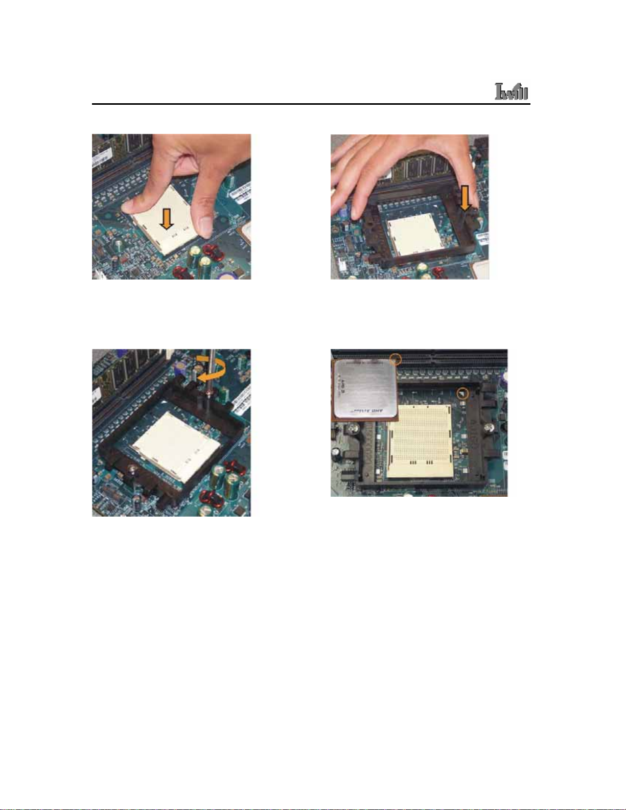
Step 3
1. Gently lift the motherboard by the edges over the backplate.
2. Align the backplate’s two threaded standoffs with the two mounting holes near the socket.
3. Gently lower the motherboard until the standoffs fit through the holes in the motherboard and the backplate makes
complete contact with the motherboard.
1. Place the backplate on a flat surface.
2. Peel the release liner off the backplate
________________________________________________________________________
Hardware Installation 2-11
Page 26
DK8X Motherboard
Step 4
Step 5.
Press firmly on the socket to ensure
proper contact of the backplate and
motherboard.
Step 6
1. Place the screws and tighten
down the retention frame.
2. Do not over-tighten the screws.
3. Ensure that the retention frame
is flat with the motherboard.
Carefully place the retention frame
on the motherboard.
The screw holes must align with the
backplate standoffs.
Step 7
Warning: Do not apply voltage until the heatsink is fully
1. The AMD Opteron. processor will have a small triangle
2. To insert the processor, the socket locking lever must
3. Gently place the processor into the socket. The corner
4. Be careful not to bend the processor pins.
installed. If voltage is applied before the heatsink
is fully installed, the processor will overheat and
failure will result.
marking on one corner. This will correspond to the
alignment on the motherboard.
be raised (Pull out slightly, then lift up).
with the triangle must be located near the marking on
the motherboard.
________________________________________________________________________
2-12 Hardware Installation
Page 27

Chapter 2 Hardware Installation
Step 8
1. Gently push down on the processor while
lowering the locking lever and latching it into the
fully locked position.
2. Do not apply any power (voltage) to the system
until the heatsink is fully installed.
Step 10
Step 9
1. The heatsink has a thermal interface material
pre-applied on the bottom. This material is protected
by a plastic cover.
2. Inspect the thermal interface material for scratches
or gaps. Do not use if thermal material has
scratches or gaps. If replacement thermal interface
material is needed,
3. Remove plastic cover and discard. Be careful not to
touch or scratch the thermal interface material.
Step 11
1. Place the heatsink on the processor with it
centered in the retention frame matching the
heatsink clip with the socket mounting lug.
2. The heatsink should have full contact with the
processor.
Hook the spring clip under the cam lever to the mounting
lug on the retention frame first. Some force may need to
be applied.
________________________________________________________________________
Hardware Installation 2-13
Page 28

DK8X Motherboard
Step 12
1. Make sure the retention clip is aligned with
the plastic lug on the retention frame.
2. Carefully push straight down on the clip.
This may take more force than the first side.
Step 14
Step 13
The spring clip must be installed as shown.
Step 15
Carefully turn the cam lever to lock into place.
Connect the fan power lead to the proper connector to the motherboard.
Check the installation completely to make sure heatsink is installed correctly before starting the system. When the system
is first powered-on, verify that the processor heatsink/fan is turning at a rapid rate.
If the fan is spinning at a slow rate or not spinning at all, power-down the system immediately to avoid any thermal damage.
Ensure the cam lever is locked into the retention frame.
Important: In single CPU mode, please place CPU on the position of CPU0
________________________________________________________________________
2-14 Hardware Installation
Page 29

Chapter 2 Hardware Installation
THE AGP PRO SLOT
The Mainboard does not feature an integrated video solution. Therefore, you will need to
install a video card to use the Mainboard. The Accelerated Graphics Port Pro (AGP Pro)
slot is specifically designed to support a new generation of AGP graphics cards with
ultra-high memory bandwidths (up to 8x).
IMPORTANT
* Only 1.5V AGP 4X/8X cards are supported by this 8x AGP Pro slot. Refer to the
documentation that came with your AGP card for more information on Card
Settings.
________________________________________________________________________
Hardware Installation 2-15
Page 30

DK8X Motherboard
EPS12V POWER CONNECTORS
Find the proper orientation of the connectors and push down firmly to make sure that the
pins are aligned (the connector will only insert properly when properly aligned). The
8-pin connector is a dedicated power connector to supply power for the CPUs. For Wake
on LAN support, the 5-volt Stand-by lead (+5VSB) from the ATX power supply must
supply at least 2A.
IMPORTANT
It is recommended that you use an ATX Power Supply that complies with the Intel ATX
2.03 specification.
EPS12V PSU Only
________________________________________________________________________
2-16 Hardware Installation
Page 31

Chapter 2 Hardware Installation
FLOPPY DISK DRIVE CONNECTOR
This 34-pin connector supports the standard floppy disk drive ribbon cable. Connect the
single connector end to the Mainboard. Then, plug the other end of the ribbon into the
floppy drive. Make sure you align the Pin 1 on the connector with the Pin 1 alignments
on the Mainboard and the floppy drive.
PRIMARY IDE CONNECTORS
The two 40-pin IDE connectors (primary and secondary channels) support 80-conductor
IDE ribbon cables. Connect the single connector end to the Mainboard. Then, connect the
two connectors at the other end to your IDE device(s). If you connect two hard disks to
the same cable, you must set the second drive as a Slave through its jumpers settings.
Refer to the IDE device's documentation for the specific jumper settings. (Pin 20 is
removed to prevent the connector from being insertied in the wrong orientation when
using ribbon cables with pin 20 plugged in). The BIOS supports Ultra DMA
33/66/100/133.
Pin 1
________________________________________________________________________
Hardware Installation 2-17
Page 32

DK8X Motherboard
IMPORTANT
Ribbon cables should always be connected with the red stripe on the Pin 1 side of the
connector. IDE ribbon cables must be less than 46 cm (18 inches) long, with the second
drive connector no more than 15 cm (6 inches) away from the first connector.
RONT PANEL SWITCHES
F
The front panel switches header connects the front control panel buttons and LEDs to the
Mainboard.
JPANEL1: Front Panel Connector Pin Assignments
________________________________________________________________________
2-18 Hardware Installation
Page 33

Chapter 2 Hardware Installation
Reset Switch (2-pin RST)
This 2-pin connector connects to the chassis-mounted reset switch for rebooting your
computer without turning your power switch off and on. This is a preferred method of
rebooting your system to prolong the life of your system’s power supply.
Hard Disk Activity LED (2-pin HDD_LED)
This connector supplies power to the chassis's HDD/IDE activity LED. Read and Write
activity by devices connected to the Primary or Secondary IDE connectors will cause the
front panel LED to light up.
Speaker Connector (4-pin SPEAKER)
There is one jumper over pin1 and pin2 (default setting) for the internal buzzer. If you
want to use the external case-mounted speaker instead of the internal buzzer, remove the
jumper and connect the speaker wire to the 4-pin connector.
ATX Power Switch / Soft Power Switch (2-pin PWR_SW)
A momentary switch connected to this 2-pin connector controls the system power.
Pressing the button once will switch the system between ON and SLEEP mode. The
system power LED shows the status of the system’s power.
System Power LED (3-pin PWR_LED)
This 3-pin connector connects to the chassis-mounted system power LED, which lights
up when the system is powered on.
________________________________________________________________________
Hardware Installation 2-19
Page 34

DK8X Motherboard
CPU/ SYSTEM FAN CONNECTORS
There are seven 3-pin fan connectors in the Mainboard motherboard. Two fans are used
for CPU0 and CPU1; five are for system and front. These connectors support cooling
fans of 500mA (6W) or less. Depending on the fan manufacturer, the wiring and plug
may be different. Connect the fan’s plug to the Mainboard with respect to the polarity of
the fan connector. CPU0_FAN, CPU1_FAN and SysFAN0 support Smart Fan function.
WARNING
The CPU and/or motherboard will overheat if there is not enough airflow across the CPU
and onboard heatsink. Damage may occur to the motherboard and/or the CPU fan if these
pins are incorrectly used. These are NOT jumpers, do NOT place jumper caps over these
pins.
________________________________________________________________________
2-20 Hardware Installation
Page 35

Chapter 2 Hardware Installation
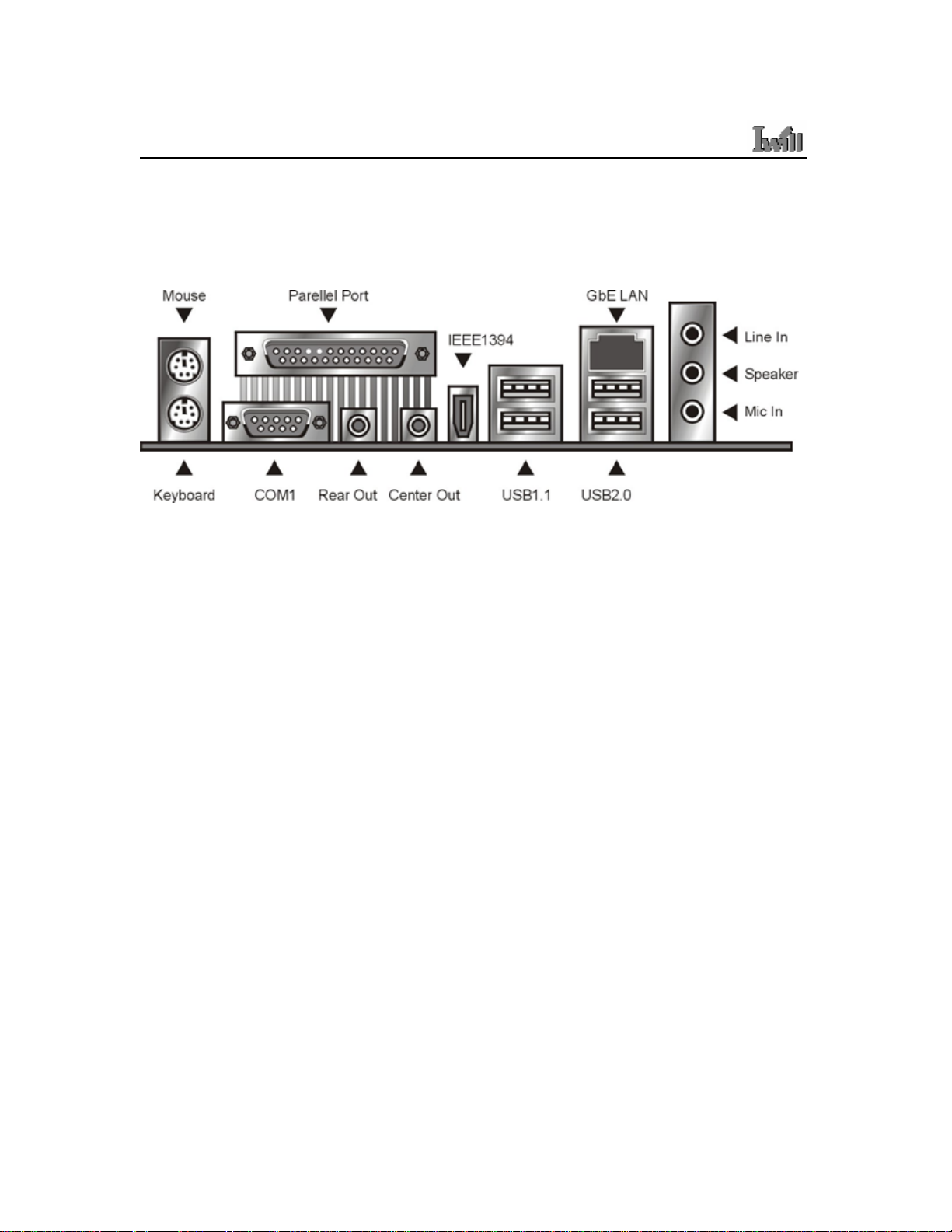
REAR PANEL I/O PORTS
This is an illustration of the Mainboard rear I/O port array
PS/2 Mouse Connector (6-pin Female)
The system will direct IRQ12 to the PS/2 mouse if one is detected. If no mouse is
detected, IRQ12 will be free for expansion cards to use.
PS/2 Keyboard Connector (6-pin Female)
This connection is for standard keyboards using a PS/2 (mini DIN) plug. This connector
will not accept standard AT size (large DIN) keyboard plugs. You may need a DIN to
mini DIN adapter for standard AT keyboards.
Universal Serial Bus Ports (4-pin Female)
Two (2) onboard external USB 2.0 ports and two (2) onboard external USB 1.1 ports are
available for connecting USB devices. Refer to USB 2.0 Ports & Header for more
information.
________________________________________________________________________
Hardware Installation 2-21
Page 36

DK8X Motherboard
IEEE 1394/ FireWire Connector (6-pin Male)
Depending on your Mainboard model, you may have one (1) onboard IEEE 1394
connector port for connecting FireWire devices. Refer to IEEE 1394 Ports & Header for
more information.
Serial Port (COM1) Connector (9-pin Male)
The COM1 serial port can be used for pointing devices or other serial devices. See BIOS
for more on serial port setup.
Parallel Printer Connector (25-pin Female)
You can enable the parallel port and choose an IRQ through the BIOS. You can choose
between ECP and EPP support through the BIOS setup.
Onboard LAN Port (RJ-45)
This Mainboard uses the 3COM 3C940 Gigabit Ethernet Controller. The controller
consists of both the Media Access Controller (MAC) and Mbps Physical Layer (PHY)
interface. Refer to the ¡§Onboard LAN User Guide¡¨ for further information.
Audio Jacks (Phone Jacks)
The interface with the onboard RealTek ALC-655. It has 3 phone jacks for Speaker-Out,
Microphone In, and Line-In. Besides, there are two phone jacks for Rear Out and Center
Out.
________________________________________________________________________
2-22 Hardware Installation
Page 37

Chapter 2 Hardware Installation
ADDITIONAL I/O CONNECTORS
The Mainboard also contains connectors for adding additional ports and devices to the
Mainboard.
CD_In & Aux_In Audio Inputs (4-pin)
There are both CD-In and Aux-In 4-pin connectors to connect your internal sound
devices to the Sound Card. See Audio for setup inform ation.
4-pin Onboard Audio Header
2.0 PORTS AND HEADER
USB
The Serial Version of this Mainboard features the NEC chip integrated into the board.
This chip supports four (4) USB 2.0 ports. USB 2.0 supports transfer rates of up to
480MB/s. All four ports show up on the on-board I/O array.
________________________________________________________________________
Hardware Installation 2-23
Page 38

DK8X Motherboard
IEEE 1394 (FIREWIRE) PORTS AND HEADER
This Mainboard features an integrated Texas Instrument TSB43AB22 chip which
supports two (2) IEEE 1394 (Firewire) ports. IEEE 1394 (FireWire) supports transfer
rates of up to 400MB/s. One port is installed on the on-board I/O array, and a header
completes the last port for external installation.
________________________________________________________________________
2-24 Hardware Installation
Page 39

Chapter 2 Hardware Installation
INSTALLING EXPANSION CARDS
This outlines the procedure for adding expansion cards to your Mainboard. Remember to
read the documentation for your expansion cards and make the necessary hardware and
software setting changes (i.e. jumper settings).
The Mainboard features two (2) PCI-32 (32-bit, 33MHz) slots, one (1) PCI-64 (64-bit,
66/33MHz) slot and two (2) PCI-X (100/133MHz) slots to accommodate PCI expansion
cards.
1. Remove the bracket plate on the slot you intend to use. Keep the bracket for possible
future use.
2. Insert the PCI card into the correct slot on the Mainboard, pushing down with your
thumbs evenly on both sides of the card.
3. Secure the card on the slot with the screw you removed above.
4. Assign IRQs for PCI expansion card: An IRQ number is automatically assigned to PCI
expansion card. In the PCI bus design, the BIOS automatically assigns an IRQ to a PCI
slot that contains a card requiring an IRQ.
WARNING
Completely power OFF your power supply when adding or removing any expansion
cards or other system components. Failure to do so may cause severe damage to both
your Mainboard and expansion cards.
________________________________________________________________________
Hardware Installation 2-25
Page 40

DK8X Motherboard
SILICON IMAGE CHIPSET AND SERIAL ATA
The Serial version of this Mainboard is equipped with an integrated Silicon Image
Sil3114 Serial ATA chipset. This chipset supports up to 4 SATA devices at transfer rates
of up to 150MB/s.
The Silicon Image Chipset also supports RAID configurations. RAID stands for
"Redundant Array of Independent Devices" and provides different levels of safety,
redundancy and performance. This chipset supports RAID 0, 1, and 10, which are defined
as follows:
RAID Type Description
RAID 0 Striping: high performance, designed ot connect multiple drives to act as one
RAID 1
RAID 10
This Mainboard features four (4) Serial ATA ports for 4 Serial ATA devices. Refer to the
documentation that came with the drives for more information about settings and
installation.
Mirroring: writes data to two drives at once in case one drive fails, the other
one will be a complete replica and can continue on. Full fail-over
Combination of RAID 0 and 1: over 4 drives, The drives are split in half and
striped together, and the 2 new striped drives are then mirrored.
________________________________________________________________________
2-26 Hardware Installation
Page 41

Chapter 2 Hardware Installation
POWERING ON YOUR SYSTEM
Follow these instructions to power on the computer after you have installed the
Mainboard and all system devices.
1. Be sure that all switches are off (in some systems, Off is marked by “O”).
2. After double-checking all jumper settings and connections, close the system chassis
cover.
3. Connect the power cord to the power cord connector located on the power supply at
the back of your system chassis and plug the power cord into a power outlet that is
equipped with a surge protector.
4. Turn on your devices in the following order:
- Monitor
- External SCSI devices (starting with the last device on the chain if connected)
- System power For power supplies, you need to switch On the power supply, then
press the:
1. Power switch on the front of the chassis the first time you start up the system.
2. The power LED on the front panel of the system case will light up. For power
supplies, the system LED will light up when the power switch is pressed. The monitor
LED may light up after the system’s LED if it complies with “Green” standards or if
it has a power standby feature. The system will first run its “power-on” tests. While
the tests are running, additional messages will appear on the screen. If you do not see
anything on the screen within 30 seconds from the time you turn on the power, the
system may have failed a power-on test. Re-check your jumper settings and
connections. Contact your retailer/dealer for assistance if everything else fail.
3. During power-on, hold down <F2> to enter BIOS setup. Follow the instructions in
BIOS for further setup information.
________________________________________________________________________
Hardware Installation 2-27
Page 42

DK8X Motherboard
BIOS Setup
This chapter discusses the AMIBIOS Setup program built into the ROM BIOS. The Setu p
program allows users to modify the basic system configuration.
The BIOS is the Basic Input / Output System used in all IBM PC, XT, AT, and PS/2
compatible computers. The AMIBIOS flash chip stores the system parameters, such as
type of disk drives, video displays, etc. in the CMOS. When the computer is turned off, a
back-up battery provides power to the BIOS flash chip, enabling it to retain system
parameters. Each time the computer is powered-on the computer is configured with the
values stored in the BIOS ROM by the system BIOS, which gains control at boot-up.
The AMIBIOS installed in your computer system’s ROM (Read Only Memory) is a
custom version of an industry standard BIOS. The BIOS provides critical low-level
support for standard devices such as disk drives and serial and parallel ports.
TARTING THE BIOS SETUP
S
The AMIBIOS is immediately activated every time you power on the system. The BIOS
reads the system information contained in the CMOS and begins the process of checking
the system and configuring it. After configuring the system, the BIOS will follow the
Boot Order to seek out an operating system. The BIOS then turns control of the system
over to the operating system.
The CMOS information that determines the system parameters may be changed by
entering the BIOS Setup utility.
1. Power on the System.
Note: Normally, the only visible POST (Power On Self Test) routine is the
memory test.
________________________________________________________________________
3-1 BIOS Setup
Page 43

Chapter 3 BIOS Setup
2. As the memory is being tested, you can access the BIOS Setup Utility by pressing
the <F2> key when “Press < F2> to enter SETUP” appears briefly at the bottom
of the screen.
From the main menu of the BIOS Setup Utility, you can access the other setup screens,
such as the Security and Power menus.
SING THE BIOS SETUP UTILITY
U
Navigating through the BIOS Setup Utility is straight forward. Use the arrow keys to
highlight items, press <Enter> to select items in menus, and press <Esc> to quit. The
following table provides more details about how to navigate in the Setup program using
the keyboard.
Up ArrowKey Move to the previous item
Down Arrow Key Move to the next item
Left Arrow Key Move to the previous menu
Right Arrow Key Move to the next menu
In the Submenu: Exit the submenu.
<Esc> key
In the BIOS main menu: Jump to the Exit Menu
Select the highlighted item. When available, a
<Enter> Key
pop-up list will display for you to select the
item value or select a submenu
Previous page on Scrollable menus or Jump to
<PgUp> Key
the first interactive item listed
Next page on Scrollable menus or Jump to the
<PgDn> Key
last interactive item listed
<F1> Key General Help on Setup navigation keys.
<F2>/<F3> Key Change Colors
<F7> Key Discard Changes
________________________________________________________________________
BIOS Setup 3-2
Page 44

DK8X Motherboard
<F8> Key Load Failsafe Defaults
<F9> Key Load Optimal Defaults
<F10> Key Save and Exit
Home Go to Top of Screen
END Go to Bottom of Screen
ESC Exit
IMPORTANT
The BIOS does NOT automatically save values that you have modified. If you do not
save your values before you exit the BIOS Setup Utility, all your changes will be lost.
If after making and saving system changes with the BIOS Setup Utility, you discover that
your computer is no longer able to boot, the AMIBIOS supports an override, which will
reset your system to the Failsafe defaults. If that fails, it is possible to manually clear the
present CMOS information through the "Clear CMOS Header" on the motherboard
(Refer to Jumper Settings for more information).
The best advice is to ONLY alter settings which you thoroughly understand. The default
settings have been carefully chosen by AMIBIOS to provide the maximum system
performance and reliability. Even a slight change to the chipset setup may cause potential
and unpredictable failure to the system.
________________________________________________________________________
3-3 BIOS Setup
Page 45

Chapter 3 BIOS Setup
Main Menu
This is the first screen that is displayed when you enter the BIOS Setup Utility. Each tab
lined on the top of the screen represents each different menu. The following picture
shows the main menu. Main menu shows the information of BIOS version, date and ID;
processor type, speed and count; system size. In addition, system time and date is
adjustable using + / - key or number keys.
________________________________________________________________________
BIOS Setup 3-4
Page 46

DK8X Motherboard
Advanced Menu
This is the Advanced Menu screen.
You can make these modifications on the Advanced menu.
You can make these modifications on the Advanced Menu. Select the Submenus to
modify those settings.
Feature Option Description
Disabled
360 KB, 5 1/2”
1.2 MB, 5 1/2”
Floppy Configuration
720 KB, 3 1/2”
1.44 MB, 3 1/2”
2.88 MB, 3 1/2”
H/W health function and
Hardware Health
H/W thermal throttling
Configuration
Disabled/Enabled
Select Floppy A or Floppy B
and then selects
floppy-diskette type installed
in your system.
1. Enable/Disable H/W
health function
2. Thermal throttling allows
the user to reduce CPU
duty cycle to a user
________________________________________________________________________
3-5 BIOS Setup
Page 47

Chapter 3 BIOS Setup
Feature Option Description
ACPI Configuration
Hyper Transport
Configuration
Remote Access
Configuration
USB Configuration
ACPI Aware O/S
Yes/No
CPU0 : CPU1 HT Link
Speed/Width
Disable
Serial
Legacy USB Support
Disabled/Enabled/Auto
USB Mass Storage Device
Configuration
defined percentage when
the temperature reaches a
user defined value
3. H/W health event
Enable: If O/S supports
ACPI
Disable: If O/S doesn’t
support ACPI
Hyper Transport link
speed/width is adjustable
Selects Remote Access type
1. Enables support for
legacy USB. Auto option
disables legacy support if
no USB devices are
connected
2. Configure the USB mass
storage class devices
________________________________________________________________________
BIOS Setup 3-6
Page 48

DK8X Motherboard
IDE Configuration Submenu
Feature Option Description
Onboard PCI IDE Controller
Disabled
Primary
Secondary
Both
Disabled
Hard Disk Write Protect
Enabled
________________________________________________________________________
Disabled: disables the
integrated IDE controller
Primary: enables only the
Primary IDE controller
Secondary: enables only the
secondary IDE controller
Both: enables both IDE
controllers
Disable/Enable device write
protection. This will be
effective only device is
accessed through BIOS
3-7 BIOS Setup
Page 49

Chapter 3 BIOS Setup
IDE Detect Time Out (Sec) 0, 5, 10, 15, 20, 25, 30, 35
Host & Device
ATA(PI) 80Pin Cable Detection
Host
Device
Super IO Configuration Submenu
Select the time out value for
detecting ATA/AT API device
Select the mechanism for
detecting 80 pin cable
Feature Option Description
Disabled
Allows BIOS to enable or
Onboard Floppy Controller
Onboard Game/Midi Port
Enabled
Disabled
200/300, 200/330
disable floppy controller
Allows BIOS to enable or
disable Game/Midi port
208/300, 208/330
Keyboard PowerOn Function Disabled
Any Key
________________________________________________________________________
BIOS Setup 3-8
Page 50

DK8X Motherboard
PCIPnP Menu
________________________________________________________________________
3-9 BIOS Setup
Page 51

Chapter 3 BIOS Setup
b
b
Feature Option Description
Yes: lets the O/S configure
Plug & Play O/S
PCI Latency Timer
Allocate IRQ to PCI VGA
Palette Snooping
Yes
No
32, 64, 96, 128, 160,
192, 224, 248
Yes
No
Disabled
Enabled
PnP devices not required for
oot if your system has a
Plug and Play O/S
Value in units of PCI clocks
for PCI device latency timer
register
Yes: Assign IRQ to PCI
VGA card if card requests
IRQ
No: Doesn’t assign IRQ To
PCI VGA cars even if card
requests IRQ
Enabled: informs the PCI
devices that an ISA graphics
device is installed in the
system so the card will
function correctly
PCI IDE BusMaster
Offboard PCI/ISA IDE card
________________________________________________________________________
BIOS Setup 3-10
Disabled
Enabled
Auto
PCI Slot1
PCI Slot2
PCI Slot3
PCI Slot4
PCI Slot5
PCI Slot6
Enabled: BIOS uses PCI
usmastering for
reading/writing to IDE drives
Some PCI IDE cards may
require this to be set to the
PCI slot number that is
holding the card.
Page 52

DK8X Motherboard
Feature Option Description
Available: specified IRQ is
available to be used by
IRQ3~IRQ15
DMA Channel 0, 1, 3, 5, 6, 7
Reserved Memory Size
Available
Reserved
Available
Reserved
Disabled
16K
32K
64K
PCI/PnP devices
Reserve: specified IRQ is
reserved for use by legacy
ISA devices
Available: specified DMA is
available to be used by
PCI/PnP devices
Reserve: specified DMA is
reserved for use by legacy
ISA devices
Size of memory block to
reserve for legacy ISA
devices
________________________________________________________________________
3-11 BIOS Setup
Page 53

Chapter 3 BIOS Setup
Boot Menu
Feature Description
Boot Device Priority Specify the boot device priority sequence
Hard Disk Drives
Removable Drives
ATAPI CDROM Drives
Specify the boot device priority sequence
from available hard drives
Specify the boot device priority sequence
from available removable drives
Specify the boot device priority sequence
from available ATAPI CDROM drives
________________________________________________________________________
BIOS Setup 3-12
Page 54

DK8X Motherboard
Boot Setting Configuration Submenu
Feature Option Description
Quick Boot
Quiet Boot
AddOn ROM Display Mode
Bootup Num-Lock
PS/2 Mouse Support
Typematic Rate
Disabled
Enabled
Disabled
Enabled
Force BIOS
Keep Current
Off
On
Disabled
Enabled
Slow
Fast
Allows BIOS to skip tests
while booting
Disabled: display normal
POST messages
Enabled: display OEM logo
Set display mode for option
ROM
Select power on state for
NumLock
Select support for PS/2
mouse
Select keyboard typematic
rate
________________________________________________________________________
3-13 BIOS Setup
Page 55

Chapter 3 BIOS Setup
System Keyboard
Parity Check
Boot to OS/2
Wait for “F1” if error
Hit ‘DEL’ Message Display
Interrupt 19 Capture
Absent
Present
Disabled
Enabled
No
Yes
Disabled
Enabled
Disabled
Enabled
Disabled
Enabled
Enable/Disable all keyboards
attached to the system
Enable/Disable memory or
parity error check
OS/2 compatibility mode
Wait for F1 key to be pressed
if error occurs
Display “Press DEL to run
Setup” in POST
Enabled: allows option
ROMs to trap interrupt 19
________________________________________________________________________
BIOS Setup 3-14
Page 56

DK8X Motherboard
Security Menu
Feature Option Description
Change User Password
Clear User Password
Password Check
Boot Sector Virus Protection
Install or change the
password
Immediately clears the User
password
Setup: check password while
invoking setup
Always: check password
while invoking setup as well
as on each boot
Disabled
Enabled
Enable/Disable Boot Sector
Virus Protection
________________________________________________________________________
3-15 BIOS Setup
Page 57

Chapter 3 BIOS Setup
Chipset Menu
There are three submenus inside Chipset menu: NorthBridge Configuration, SouthBridge
Configuration and AGP Configuration.
NothBridge Configuration Submenu
Memory Configuration Submenu
________________________________________________________________________
BIOS Setup 3-16
Page 58

DK8X Motherboard
Feature Option Description
Interleaving allows memory
Bank Interleaving
Node Interleaving
Burst Length
Auto
accesses to be spread out
over BANKS on the same
Disabled
node, or across NODES,
decreasing access contention
Interleaving allows memory
accesses to be spread out
Auto
over BANKS on the same
Disabled
node, or across NODES,
decreasing access contention
Burst length can be set to 8
8 Beats
or 4 beats. 64 bit Dq must
4 Beats
use the 4 beats
________________________________________________________________________
3-17 BIOS Setup
Page 59

Chapter 3 BIOS Setup
ECC Configuration Submenu
Feature Option Description
Master ECC Enable
Master ECC Enables support
Disabled
on all nodes for ECC error
Enabled
detect and correction
________________________________________________________________________
BIOS Setup 3-18
Page 60

DK8X Motherboard
SouthBridge Configuration
Feature Option Description
2.0 SM Bus Controller
Disabled
Enabled
Auto
HT Link 0 P-Comp Mode
Data
HT Link 0 N-Comp Mode
Calcomp+ Data
HT Link 0 RZ-Comp Mode
Calcomp- Data
________________________________________________________________________
Auto causes hardware
compensation vales. Other
choices allow the user to
override default
compensation with an
absolute value, add to the
hardware generated value, or
subtract a value from the
generated value
3-19 BIOS Setup
Page 61

Chapter 3 BIOS Setup
AGP Configuration Submenu
Feature Option Description
AGP Data Transfer Rate
Aperture Size
FW Enable
P Data drive Strength
1x / 2x / 4x / 8x
1x / 2x / 4x
32, 64, 128, 256, 512, 1024,
2056 MB
Enabled
Disabled
Auto Comp
Aperture size defines a
Window into system memory
for the AGP video controller.
It doesn’t consume real
system memory
N Data drive Strength
P Strobe Drive Strength
N Strobe Drive Strength
BIOS Setup 3-20
Fixed Comp
Auto + Value
Auto - Value
Page 62

DK8X Motherboard
APM Configuration Menu
________________________________________________________________________
3-21 BIOS Setup
Page 63

Chapter 3 BIOS Setup
Exit Menu
Feature Description
Save Changes and Exit
Discard Changes and Exit
Discard Changes
Load Optimal Defaults
Load Failsafe Defaults
Exit system setup after saving the changes.
F10 key can be used for this operation
Exit system setup without saving the
changes. ESC key can be used for this
operation
Discard changes done so far to any of the
setup questions. F7 key can be used for this
operation
Load optimal default values for all the setup
questions. F9 key can be used for this
operation
Load Failsafe default values for all the setup
questions. F8 key can be used for this
operation
________________________________________________________________________
BIOS Setup 3-22
Page 64

DK8X Motherboard
Important: Driver Installation Procedure
Please follow the installation procedure belows.
1. Install WindowsXP SP1a
2. Install 8151 driver:
a. Install 8151 river from the following driver path:
CD-ROM\Drivers\AMD\8151\setup.exe
b. Update 8151 driver from the following driver path:
CD-ROM\Drivers\AMD\8151\8151 v8.10\XP\English
3. Install APIC driver: the driver path is CD-ROM\Drivers\AMD\8111\APIC\setup.exe
4. Install SMC driver: the driver path is CD-ROM\Drivers\AMD\8111\SMC
5. Install ALC655 audio driver
6. Install LAN driver: the driver path is CD-ROM\Drivers\LAN\3C940
7. Install Silicon Image Sil3114 driver
8. Install NEC USB 2.0 driver
9. Install Direct-X 9.0b driver
10. Install AGP card driver
Please be noted that the O/S environment of Windows XP for AMD Opteron 64-bit (beta
version ) is recommended.
 Loading...