

Page 1

CoreBuilder™ 5000
®
Token Ring Media Modules
User Guide
http://www.3com.com/
Document Number 17-00513-4
Published May 1997
Page 2

3Com Corporation
5400 Bayfront Plaza
Santa Clara, California
95052-8145
Copyright © 3Com Corporation, 1997. All rights reserved. No part of this documentation may be
reproduced in any form or by any means, or used to make any derivative work (such as translation,
transformation, or adaptation) without permission from 3Com Corporation. Portions of this document are
reproduced in whole or part with permission from third parties.
3Com Corporation reserves the right to revise this documentation and to make changes in content from
time to time without obligation on the part of 3Com Corporation to provide notification of such revision or
change.
3Com Corporation provides this documentation without warranty of any kind, either implied or expressed,
including, but not limited to, the implied warranties of merchantability and fitness for a particular purpose.
3Com may make improvements or changes in the products or programs described in this documentation at
any time.
UNITED STATES GOVERNMENT LEGENDS:
If you are a United States government agency, then this documentation and the software described herein
are provided to you subject to the following restricted rights:
For units of the Department of Defense:
Restricted Rights Legend: Use, duplication, or disclosure by the Government is subject to restrictions as set
forth in subparagraph (c) (1) (ii) for Restricted Rights in Technical Data and Computer Software Clause at
48 C.F.R. 52.227-7013.
For civilian agencies:
Restricted Rights Legend: Use, reproduction, or disclosure is subject to restrictions set forth in subparagraph
(a) through (d) of the Commercial Computer Software – Restricted Rights Clause at 48 C.F.R. 52.227-19
and the limitations set forth in the 3Com Corporation standard commercial agreement for the software.
Unpublished rights reserved under the copyright laws of the United States.
If there is any software on removable media described in this documentation, it is furnished under a license
agreement included with the product as a separate document, in the hardcopy documentation, or on the
removable media in a directory file named LICENSE.TXT. If you are unable to locate a copy, please contact
3Com and a copy will be sent to you.
Federal Communications Commission Notice
This equipment was tested and found to comply with the limits for a Class A digital device, pursuant to
Part 15 of the FCC Rules. These limits are designed to provide reasonable protection against harmful
interference when the equipment is operated in a commercial environment. This equipment generates,
uses, and can radiate radio frequency energy and, if not installed and used in accordance with the
instruction manual, may cause harmful interference to radio communications. Operation of this equipment
in a residential area is likely to cause harmful interference, in which case you must correct the interference
at your own expense.
Canadian Emissions Requirements
This Class A digital apparatus meets all requirements of the Canadian Interference-Causing Equipment
Regulations.
Cet appareil numérique de la classe A respecte toutes les exigences du Règlement sur le matériel brouilleur
du Canada.
EMC Directive Compliance
This equipment was tested and conforms to the Council Directive 89/336/EEC for electromagnetic
compatibility. Conformity with this directive is based upon compliance with the following harmonized
standards:
EN 55022 – Limits and Methods of Measurement of Radio Interference
EN 50082-1 – Electromagnetic Compatibility Generic Immunity Standard: Residential, Commercial, and
Light Industry
Warning: This is a Class A product. In a domestic environment, this product may cause radio interference, in
which case you may be required to take adequate measures.
Compliance with this directive depends on the use of shielded cables.
Low Voltage Directive Compliance
This equipment was tested and conforms to the Council Directive 72/23/EEC for safety of electrical
equipment. Conformity with this directive is based upon compliance with the following harmonized
standard:
EN 60950 – Safety of Information Technology Equipment
ii
Page 3

VCCI Class 1 Compliance
This equipment is in the 1st Class category (information equipment to be used in commercial or industrial
areas) and conforms to the standards set by the Voluntary Control Council for Interference by Information
Technology Equipment aimed at preventing radio interference in commercial or industrial areas.
Consequently, when the equipment is used in a residential area or in an adjacent area, radio interference
may be caused to radio and TV receivers, and so on.
Read the instructions for correct handling.
Fiber Cable Classification Notice
Use this equipment only with fiber cable classified by Underwriters Laboratories as to fire and smoke
characteristics in accordance with Section 770-2(b) and Section 725-2(b) of the National Electrical Code.
UK General Approval Statement
The CoreBuilder 5000 Integrated System Hub and ONline System Concentrator are manufactured to the
International Safety Standard EN 60950 and are approved in the U.K. under the General Approval Number
NS/G/12345/J/100003 for indirect connection to the public telecommunication network.
Trademarks
Unless otherwise indicated, 3Com registered trademarks are registered in the United States and may or may
not be registered in other countries.
3Com, Boundary Routing, CardFacts, EtherLink, LANplex, LANsentry, LinkBuilder, NETBuilder, NETBuilder II,
NetFacts, Parallel Tasking, SmartAgent, TokenDisk, TokenLink, Transcend, TriChannel, and ViewBuilder are
registered trademarks of 3Com Corporation.
3TECH, CELLplex, CoreBuilder, EtherDisk, EtherLink II, FDDILink, MultiProbe, NetProbe, and ONline are
trademarks of 3Com Corporation.
3ComFacts is a service mark of 3Com Corporation.
The 3Com Multichannel Architecture Communications System is registered under U.S. Patent
Number 5,301,303.
AT&T is a registered trademark of American Telephone and Telegraph Company.
Banyan and VINES are registered trademarks of Banyan Systems Inc.
CompuServe is a registered trademark of CompuServe, Inc.
DEC, DECnet, DELNI, POLYCENTER, VAX, VT100, VT220, and the Digital logo are trademarks of Digital
Equipment Corporation.
Hayes is a registered trademark of Hayes Microcomputer Products.
OpenView is a registered trademark of Hewlett-Packard Company.
Intel is a registered trademark of Intel Corporation.
AIX, IBM, and NetView are registered trademarks of International Business Machines Corporation.
Microsoft, MS-DOS, Windows, Windows 95, and Windows NT are registered trademarks of
Microsoft Corporation.
V30 is a trademark of NEC Corporation.
NetWare and Novell are registered trademarks of Novell, Incorporated.
IPX is a trademark of Novell, Incorporated.
OSF and OSF/Motif are registered trademarks of Open Software Foundation, Inc.
ONC, OpenWindows, Solaris, Solstice, Sun, Sun Microsystems, SunNet Manager, and SunOS are trademarks
of Sun Microsystems, Inc.
iii
Page 4

SPARCstation is a trademark licensed exclusively to Sun Microsystems Inc.
OPEN LOOK is a registered trademark of Unix System Laboratories, Inc.
UNIX is a registered trademark of X/Open Company, Ltd. in the United States and other countries.
Other brand and product names may be registered trademarks or trademarks of their respective holders.
iv
Page 5

CONTENTS
HOW TO USE THIS GUIDE
Audience 1
Structure of This Guide 2
Document Conventions 3
Related Documents 3
3Com Documents 4
Reference Documents 4
1 INTRODUCTION
CoreBuilder 5000 Token Ring Module Features 1-1
Port Switching 1-1
Module Switching 1-2
Automatic Ring Speed Detection 1-2
Active Port Retiming and Jitter Reduction 1-2
Reducing Internal (CoreBuilder 5000) Jitter 1-3
Reducing External (Non-CoreBuilder 5000) Jitter 1-3
Automatic Beacon Recovery 1-4
Address-to-Port Mapping 1-4
CoreBuilder 5000 Token Ring Modules 1-4
Active Per-Port Switching Media Module (6218M-ATPP) 1-5
Active Per-Module Switching Media Module (6218M-ATP) 1-7
Ring Mapping on the APM When Trunks Are Configured 1-8
Passive Media Module (6220M-TP) 1-10
Dual Fiber Repeater Module (6210M-DFR) 1-12
Jitter Attenuator Card (6200D-JA) 1-14
Where to Go From Here 1-14
Page 6

2 DESIGNING AND EXPANDING THE NETWORK
Building a CoreBuilder 5000 Token Ring Network 2-2
Additional Configuration Information 2-3
Determining the Maximum Number of Stations on a Ring 2-4
Selecting Appropriate Cable Lengths 2-4
Calculating Cable Lengths (Copper Wiring) 2-4
Additional Cable and Lobe Length Recommendations 2-5
Maximum Attenuation 2-5
Signal to NEXT Ratio 2-5
Transmitter Variation 2-5
Temperature 2-6
Cabling Standards 2-6
3Com Lobe
Cable Length Recommendations 2-6
Lobe Cabling Requirements 2-7
STP Lobe Cables 2-7
UTP/Levels 3, 4, and 5 Lobe Cables 2-8
120 ohm (Screened Twisted Pair) Lobe Cables 2-8
Connection Hardware 2-9
3Com Trunk Cable Recommendations 2-9
Copper Trunk Cables 2-9
Fiber Trunk Cables 2-9
Determining Fiber Cable Lengths Using Alternate Fiber
Diameters 2-10
Using Media Filters 2-11
Configuration Examples 2-12
Traditional Backbone Ring 2-12
Collapsed Backbone Configuration 2-14
Ring 1 Description 2-16
Ring 2 Description 2-16
Ring 3 Description 2-16
Devices Internetworked in the Master Hub 2-17
Single Extended Ring Configuration 2-17
Where to Go From Here 2-18
vi
Page 7

3 INSTALLING THE MODULE
Precautionary Procedures 3-1
Quick Installation 3-2
Unpacking Procedures 3-3
Module Overview 3-4
Using Network Monitor Cards 3-4
Setting the DIP Switches 3-5
Setting the Lobe/Trunk Jumper (6218M-ATPP and 6218M-ATP) 3-9
Installing Optional Daughter Cards 3-10
Installing a Token Ring Network Monitor Card 3-10
Installing a Token Ring Jitter Attenuator Card 3-12
Installing the Module 3-14
Copper Lobe Port Connections 3-17
Copper Ring-In/Ring-Out Trunk Connections 3-17
Fiber Ring-In/Ring-Out Connections 3-18
Where to Go From Here 3-18
4 CONFIGURING THE MODULE
Configuration Overview 4-1
Before You Begin 4-2
Configuring the Modules 4-2
Setting Network Ring Speed 4-3
Selecting a Network 4-4
Assigning Modules 4-4
Assigning Ports 4-4
Enabling Ports 4-5
Enabling Beacon Recovery 4-5
Setting Beacon Threshold 4-6
Enabling Static Ring Switching 4-6
Enabling Mismatch Resolution (Passive and Active Per-Module Media
Modules Only) 4-7
Moving Rings from Module-Level to Hub-Level 4-8
Setting Port Alert Filters 4-9
Enabling Speed Detect (Passive Module Only) 4-10
Setting Module Speed Threshold (Passive Module Only) 4-11
Configuring Trunks 4-11
Trunk Enable 4-12
vii
Page 8

Trunk Network Selection 4-12
Trunk Compatibility Mode 4-12
Saving the Configuration 4-13
Showing Module Configurations 4-13
Using the Show Module Command 4-14
Using the Show Port Command 4-15
Monitoring the Front Panel 4-16
LED and Network Verification 4-17
Using the CoreBuilder 5000 Controller Module to Verify LED
Operation 4-17
Using the DMM to Verify Network Connections 4-18
Where to Go From Here 4-18
5 TROUBLESHOOTING
General Troubleshooting Tips 5-2
Troubleshooting Using the Status LEDs 5-3
Troubleshooting Using the Module Status LED 5-3
Troubleshooting Using the Port Status LEDs 5-4
Troubleshooting Ring Problems 5-5
Problems Adding a New Station to an Operating Ring 5-5
Intermittent Errors on an Operating Ring 5-6
Ring Failures 5-6
Trunk Interoperability Problems 5-7
Technical Assistance 5-8
Where to Go From Here 5-8
A SPECIFICATIONS
Token Ring Active Per-Port Switching Media Module Specifications A-1
Token Ring Active Per-Module Switching Media Module
Specifications A-2
Token Ring Dual Fiber Repeater Module Specifications A-2
Token Ring Passive Media Module Specifications A-3
Token Ring Jitter Attenuator Card Specifications A-3
Twisted Pair (Copper) Connector Pinouts A-4
Active Per-Port and Active Per-Module Media Module Ring-In Port Adapter
Pinout A-5
viii
Page 9

B TECHNICAL SUPPORT
Online Technical Services B-1
World Wide Web Site B-2
3Com Bulletin Board Service B-2
Access by Analog Modem B-2
Access by Digital Modem B-2
3ComFacts Automated Fax Service B-3
3ComForum on CompuServe Online Service B-3
Support From Your Network Supplier B-4
Support From 3Com Corporation B-5
Returning Products for Repair B-6
Accessing the 3Com MIB B-6
Contacting 3Com Technical Publications B-7
INDEX
3COM CORPORATION LIMITED WARRANTY
ix
Page 10

Page 11

FIGURES
1-1 CoreBuilder 5000 Active Per-Port Switching Media Module 1-6
1-2 CoreBuilder 5000 Active Per-Module Switching Media Module 1-9
1-3 CoreBuilder 5000 Token Ring Passive Media Module 1-11
1-4 CoreBuilder 5000 Token Ring Dual Fiber Repeater Module 1-13
2-1 Traditional Backbone Configuration 2-13
2-2 Collapsed Backbone Configuration 2-15
2-3 Single Extended Ring Configuration 2-18
3-1 CoreBuilder 5000 Token Ring Module DIP Switch Locations 3-6
3-2 Active Per-Port Module and Active Per-Module Switching
Module Jumper Setting 3-9
3-3 Location of CoreBuilder 5000 Token Ring Network Monitor Cards 3-11
3-4 Installing a CoreBuilder 5000 Token Ring Jitter Attenuator Card 3-13
3-5 Installing a Media Module 3-15
3-6 Opened and Closed Module Ejectors 3-16
4-1 CoreBuilder 5000 Token Ring Network Mode 4-9
4-2 Media Module Faceplates 4-16
A-1 RJ-45 Connector Pinouts A-4
A-2 6200ADT-RI Ring-In Wire Diagram A-5
xi
Page 12

Page 13

TABLES
2-1 Building a CoreBuilder 5000 Token Ring Network 2-2
2-2 Maximum Station Counts 2-4
2-3 Maximum Lobe Lengths (in Meters) 2-7
2-4 STP Network Cable Specifications 2-7
2-5 UTP Level 3 Cable Specifications 2-8
2-6 UTP Level 4 Cable Specifications 2-8
2-7 UTP Level 5 Cable Specifications 2-8
2-8 120 ohm Cable Specifications 2-9
2-9 Multimode Fiber Specifications 2-10
2-10 Alternate Fiber Diameter Distances 2-10
2-11 Fiber Optical Budget 2-10
3-1 Procedures for Completing Installation 3-2
3-2 Network Select DIP Switch Settings 3-7
3-3 DIP Switch Setting, Switches 5 through 8 3-8
4-1 CoreBuilder 5000 Compatibility Settings 4-12
4-2 ONline Compatibility Settings 4-13
4-3 Media Module LED Interpretation 4-17
5-1 Troubleshooting Using the Module Status LED 5-3
5-2 Troubleshooting Using the Port Status LEDs 5-4
xiii
Page 14

Page 15

HOW TO USE THIS GUIDE
This guide explains how to install and operate the 3Com
CoreBuilder
information on managing the module using a CoreBuilder 5000
Distributed Management Module (DMM). It also describes the Jitter
Attenuator Card, which helps stabilize trunk (Ring-In/Ring-Out)
connections to non-CoreBuilder 5000 rings.
Before installing or using the Token Ring Media Modules, read Chapters
1, 2, and 3 of this guide for basic installation and operating
instructions.
5000 Token Ring Media Modules. This guide includes
Audience This guide is intended for the following people at your site:
■ Network manager or administrator
■ Hardware installer
Page 16

2 HOW TO USE THIS GUIDE
Structure of This Guide
This guide contains the following chapters:
Chapter 1, Introduction
– Introduces the functions and features of
CoreBuilder 5000 Token Ring Modules.
Chapter 2, Designing and Expanding the Network
– Shows
possible network configurations using the CoreBuilder 5000 Integrated
System Hub and the CoreBuilder 5000 Token Ring Modules.
Chapter 3, Installing the Module
– Provides illustrated procedures
for installing CoreBuilder 5000 Token Ring Media Modules into the
CoreBuilder 5000 Integrated System Hub.
Chapter 4, Configuring the Module
– Describes the network
management commands used to configure the modules. Also shows
front panel LEDs and dip switches on the module.
Chapter 5, Troubleshooting
– Provides help in isolating and
correcting problems that may arise when installing or operating
CoreBuilder 5000 Token Ring Media Modules.
Appendix A, Specifications
– Provides electrical, environmental, and
mechanical specifications for the module. In addition, this appendix
provides information on 50-pin Telco-type connectors, RJ-45
connectors, and twisted pair cables.
Appendix B, Technical Support
contacting the 3Com
®
technical support organization and for accessing
other product support services.
Index
– Lists the various methods for
Page 17

Document Conventions 3
Document Conventions
The following document conventions are used in this manual
:
Convention Indicates Example
Courier text User input In the Agent Information Form,
enter MIS in the New Contact field.
System output After pressing the Apply button, the
system displays the message
Transmitti ng data.
Bold command string Path names Before you begin, read the
readme.txt file located in
/usr/s nm /age nts .
Text in angled
brackets Italic text in
braces
Capitalized text in plain
brackets
Italics Text emphasis,
User-substituted
identifiers
Keyboard entry by
the user
document titles
In the command above, substitute
<rem_name> with the name of
the remote machine.Use the
following command to show port
details:
SHOW PORT {
Type your password and press
[ENTER].
Ensure that you press the Apply
button after you add the new
search parameters.
slot
.all} VERBOSE
Icon Notice Type Alerts you to...
Information note Important features or instructions
Caution Risk of personal safety, system damage, or loss
Warning Risk of severe personal injury
of data
Related Documents This section provides information on supporting documentation,
including:
■ 3Com Documents
■ Reference Documents
Page 18

4 HOW TO USE THIS GUIDE
3Com Documents The following documents provide additional information on 3Com
products:
CoreBuilder 5000 Integrated System Hub Installation and Operation
Guide – Provides information on the installation, operation, and
configuration of the CoreBuilder 5000 Integrated System Hub. This
guide also describes the principal features of the CoreBuilder 5000
Fault-Tolerant Controller Module.
Distributed Management Module User Guide – Provides information
on the CoreBuilder 5000 Distributed Management Module’s operation,
installation, and configuration. This guide also describes the software
commands associated with the Distributed Management Module.
Distributed Management Module Commands Guide – Describes each
management command by providing detailed information on the
command’s format, use, and description.
Token Ring Media Module Quick Reference Cards – Provide basic
configuration and monitoring information for individual CoreBuilder
5000 Token Ring module types.
For a complete list of 3Com documents, contact your 3Com
representative.
Reference Documents The following documents supply related background information:
Case, J., Fedor, M., Scoffstall, M., and J. Davin, The Simple Network
Management Protocol, RFC 1157, University of Tennessee at Knoxville,
Performance Systems International and the MIT Laboratory for
Computer Science, May 1990.
Rose, M., and K. McCloghrie, Structure and Identification of
Management Information for TCP/IP-based Internets, RFC 1155,
Performance Systems International and Hughes LAN Systems, May
1990.
Page 19

1
INTRODUCTION
CoreBuilder 5000 Token Ring Module Features
This chapter describes the 3Com CoreBuilder
Modules. For more information on the 3Com
Integrated System Hub, refer to the CoreBuilder 5000 Integrated
System Hub Installation and Operation Guide.
The chapter contains the following sections:
■ CoreBuilder 5000 Token Ring Module Features
■ CoreBuilder 5000 Token Ring Modules
This section describes the following CoreBuilder 5000 Token Ring Media
Module features:
■ Port Switching
■ Module Switching
■ Automatic Ring Speed Detection
■ Active Port Retiming and Jitter Reduction
■ Automatic Beacon Recovery
■ Address-to-Port Mapping
™
5000 Token Ring Media
®
CoreBuilder 5000
Port Switching CoreBuilder 5000 Token Ring port switching modules support per-port
switching to any combination of:
■ 10 backplane (hub-wide) Token Rings
■ 11 isolated (module-level) rings
Page 20

1-2 INTRODUCTION
Ports on the same module can be part of as many as 11 different rings.
Using per-port switching, you can move ports (and therefore users)
from ring to ring using a console attached to the hub management
module or SNMP-based network management system.
Internal management features such as automatic ring speed detection
ensure that newly-inserted ports do not disrupt ring operation.
Module Switching CoreBuilder 5000 Token Ring per-module switching modules can be
switched on a per-module basis to any of 10 CoreBuilder 5000
backplane rings or to one isolated ring.
Internal management features such as automatic ring speed detection
ensure that newly-inserted modules do not disrupt ring operation.
Automatic Ring
Speed Detection
Active Port Retiming
and Jitter Reduction
CoreBuilder 5000 Token Ring Media Modules provide automatic ring
speed detection. Automatic Ring Speed Detection is a feature that
prevents a station from entering an active ring if the station is
configured for a speed other than the active ring’s speed. This
wrong-speed detection is implemented per port, and works
automatically with speed sensing Token Ring Adapter cards.
For example, if you try to attach a station configured at 4 Mbps to an
active ring configured at 16 Mbps, the CoreBuilder 5000 Token Ring
circuitry prevents the station from entering the ring before the station’s
wrong speed causes a beaconing interruption.
CoreBuilder 5000 Token Ring ports and modules actively retime and
regenerate incoming signals, effectively increasing achievable link
distances.
■ Active retiming – Allows greater cable lengths over lower-grade
cabling, and helps ensure reliable connections. For example,
CoreBuilder 5000 Active Port Retiming Token Ring supports a
16 Mbps Token Ring over Level 3 UTP cable at distances of up to
100 meters.
■ Jitter attenuation – Is a feature that increases both the achievable
link distances and maximum number of stations.
Page 21

CoreBuilder 5000 Token Ring Module Features 1-3
Jitter is the tendency of signalling on Token Ring networks to grow
increasingly out-of-phase as the network size increases. CoreBuilder
5000 Token Ring Media Modules remedy jitter problems by:
■ Reducing Internal (CoreBuilder 5000) Jitter
■ Reducing External (Non-CoreBuilder 5000) Jitter
Reducing Internal (CoreBuilder 5000) Jitter
To minimize jitter and increase the number of stations allowed on each
ring, each CoreBuilder 5000 Token Ring active port incorporates Dual
Phase-Locked Loop (DPLL) circuitry.
Dual PLL minimizes accumulated jitter and phase slope on the ring, and
increases the number of attached stations to 250 (190 at 4 Mbps) on
each ring. To reduce jitter, DPLL uses a two-pronged approach:
■ An optimized, wide-band PLL tracks the incoming signal even in the
presence of jitter, thus allowing more margin for jitter sources.
■ A narrow-band PLL removes all fluctuations in the recovered clock
and provides a stable source to retime and retransmit the signal.
Reducing External (Non-CoreBuilder 5000) Jitter
In addition to port-level DPLLs, CoreBuilder 5000 Token Ring Media
Modules support optional Jitter Attenuator daughter cards. Daughter
cards reduce jitter accumulated in external, non-CoreBuilder 5000 rings,
even if the rings are built from other vendor’s products.
A combination of port-level DPLLs and Jitter Attenuator daughter cards
allows you to use Level 3 UTP lobe cabling to configure the following
ring (using active ports):
■ 250 stations
■ 16 Mbps ring speed
■ 100 meter lobes
A major feature of reduced jitter is reliability. A network that can
support 250 stations, under worst case conditions, is assured to be
extremely robust and reliable when configured with 50, 75, or 125
stations.
Page 22

1-4 INTRODUCTION
Automatic Beacon
Recovery
Address-to-Port
Mapping
CoreBuilder 5000 Token Ring Modules
CoreBuilder 5000 Token Rings Media Modules are equipped with:
■ Automatic, hardware-based beacon recovery on each module.
Beacon Recovery allows the modules to remove beaconing stations
from both backplane (hub-wide) and isolated (module-level) rings.
■ Beacon recovery software and the CoreBuilder 5000 Beacon
Recovery ASIC, which aids in the removal of beaconing stations.
Beacon recovery functions even in the absence of a management
module in the hub.
CoreBuilder 5000 Token Ring Media Modules provide accurate,
hardware-based address-to-port mapping, capable of mapping multiple
stations per port, even for networks that incorporate fan-out devices
and MAC-less stations (for example, network analyzers).
This section describes the following modules:
■ Active Per-Port Switching Media Module (6218M-ATPP)
■ Active Per-Module Switching Media Module (6218M-ATP)
■ Passive Media Module (6220M-TP)
■ Dual Fiber Repeater Module (6210M-DFR)
■ Jitter Attenuator Card (6200D-JA)
Page 23

CoreBuilder 5000 Token Ring Modules 1-5
Active Per-Port
Switching Media
Module
(6218M-ATPP)
The CoreBuilder 5000 Token Ring Active Per-Port Switching (ATPP)
Media Module is a single-slot module that supports 18 active retiming
lobe ports, all with port-switching capability. The module offers the
following features:
■ Switchable ports 17 and 18 provide fully-repeated Ring-In/Ring-Out
ports for connection to external rings
When configuring ports 17 and 18 as trunks, cable adapter 6200ADT-RI
must be connected on the port #18.
■ Active retiming on all media ports
■ Simultaneous shielded and unshielded twisted-pair cabling support
■ Simultaneous 4 and 16 Mbps Token Ring networks, when switched
to the appropriate ring speed
■ Can be switched on a per-port basis to any of 10 CoreBuilder 5000
backplane rings or 11 isolated rings
■ Accepts one optional Jitter Attenuation Card, for use with the
Ring-In/Ring-Out ports when connecting to a non-CoreBuilder 5000
RI/RO
■ Accepts a Token Ring Network Monitor Card (TR-NMC)
■ Address-to-port mapping, including multi-station ports (fan outs)
and MAC-less stations
■ Module-level, hardware-based beacon recovery
■ IEEE 802.5 compliant
■ IEEE 802.5c trunk support
■ Per-port jitter attenuation
■ Fan-out support for up to eight devices per port
■ Automatic ring speed detection
Page 24
1-6 INTRODUCTION
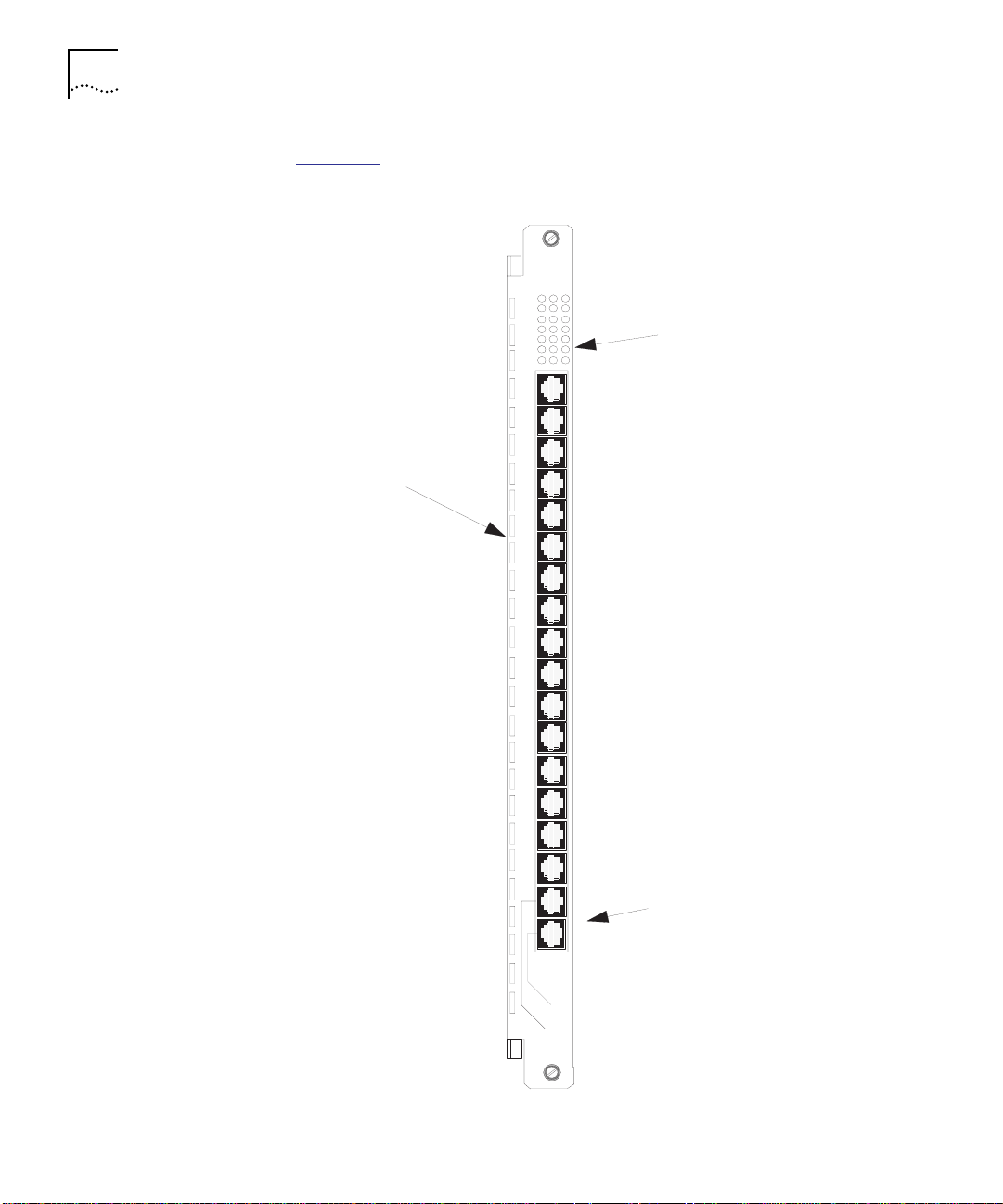
Figure 1-1 illustrates the CoreBuilder 5000 Token Ring Active Per-Port
Switching Media Module.
MOD/STAJARIRO
1
4
Actively-retimed
lobe ports
7
10
13
16
LED panel
Ports 17 and 18
configurable as
Ring-In/Ring-Out ports
1
8
/
R
1
1
7/R
O
Figure 1-1 CoreBuilder 5000 Active Per-Port Switching Media Module
Page 25

CoreBuilder 5000 Token Ring Modules 1-7
Active Per-Module
Switching Media
Module (6218M-ATP)
The CoreBuilder 5000 Token Ring Active Per-Module Switching Media
Module is a single-slot module that supports 18 active retiming lobe
ports. The module offers the following features:
■ Switchable ports 17 and 18 provide fully-repeated Ring-In/Ring-Out
ports for connection to external rings
When configuring ports 17 and 18 as trunks, cable adapter 6200ADT-RI
must be connected on the port #18.
■ Active retiming on all media ports
■ Simultaneous shielded and unshielded twisted-pair cabling support
■ Support for either 4 or 16 Mbps Token Ring networks
■ Can be switched on a per-module basis to any of ten
CoreBuilder 5000 backplane rings or to the one isolated ring
■ Accepts one optional Jitter Attenuation Card, for use with the
optional Ring-In/Ring-Out ports when connecting to
non-CoreBuilder 5000 RI/RO
■ Accepts a Token Ring Network Monitor Card (TR-NMC)
■ Address-to-port mapping, including multi-station ports (fan-outs)
and MAC-less stations
When an Active Per-Module Media Module (APM), in trunk mode only,
has fan-out devices attached in the network, the address map
information is not accurate for ports below the fan-out device. The
address map information for the other modules is accurate.
If a fan-out device is attached to an APM and the trunks on the APM
are enabled, 3Com recommends that you insert the fan-out device at
the highest numbered active port.
■ Module-level, hardware-based beacon recovery
■ IEEE 802.5 compliant
■ IEEE 802.5c trunk support
■ Per-port jitter attenuation
■ Fan-out support for up to eight devices per port
■ Automatic ring speed detection
Page 26

1-8 INTRODUCTION
Ring Mapping on the APM When Trunks Are Configured
Mismatch Resolution does not run when APM trunks are enabled,
which may result in an incorrect ring map. When trunks are enabled,
the number of entries reported on the APM is the number of ports that
have phantom. Although only the active ports are listed, there may be
a mismatch in the port to station mapping when fan-out or MAC-less
devices are present.
When a fanout or MAC-less device is attached to an APM with trunks
enabled, the address map information may be inaccurate for ports
below the fanout or MAC-less device. The address map information for
the other modules on the same network is accurate. If you use fanout
or MAC-less devices on an APM with trunks enabled, 3Com
recommends that you insert the fanout and MAC-less device at the
highest numbered active port.
Page 27

CoreBuilder 5000 Token Ring Modules 1-9
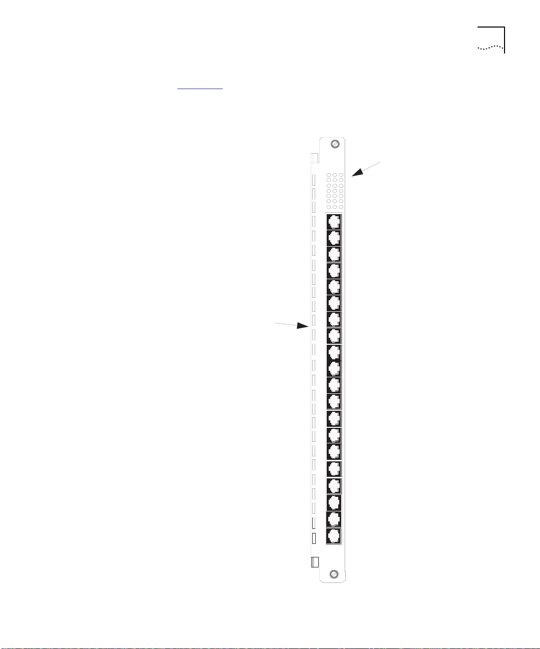
Figure 1-2 illustrates the CoreBuilder 5000 Token Ring Active
Per-Module Switching Media Module.
MOD/STAJARIRO
1
4
Actively-retimed
lobe ports
7
10
13
16
LED panel
Port s 17 an d 18
configurable as
Ring-In/Ring-Out ports
1
8
/
R
1
1
7/R
O
Figure 1-2 CoreBuilder 5000 Active Per-Module Switching Media Module
Page 28

1-10 INTRODUCTION
Passive Media
Module (6220M-TP)
The CoreBuilder 5000 Token Ring Passive Media Module is a single-slot
module that provides 20 lobe ports per module, or up to 320 users per
hub, with as many as 250 users on the same network ring.
The module has the following features:
■ Delivers a high-density passive media solution for connecting devices
to Token Ring networks.
■ Provides connections using shielded or unshielded twisted-pair
cabling (using RJ-45 connectors) on any individual module. You
cannot, however, mix both wiring types on the same module.
■ Supports a variety of twisted pair cabling, UTP categories 4 or 5.
■ Supports either 4 or 16 Mbps Token Ring networks on a per-module
basis.
■ Supports fan-out devices so that you can perform address to port
mapping of up to eight end stations per port.
■ Can be switched on a per-module basis to any of ten
CoreBuilder 5000 backplane rings or to the one isolated ring.
■ Accepts a Token Ring Network Monitor Card (TR-NMC).
■ Has built-in jitter-attenuation circuitry for module level retiming.
■ Automatic ring speed detection.
■ Address-to-port mapping, including multi-station ports (fan outs)
and MAC-less stations.
■ Module-level, hardware-based beacon recovery.
Page 29
CoreBuilder 5000 Token Ring Modules 1-11
Figure 1-3 illustrates the CoreBuilder 5000 Token Ring Passive Media
Module.
Passive media ports
3
6
9
12
15
18
MOD/STA12
LED panel
Figure 1-3 CoreBuilder 5000 Token Ring Passive Media Module
Page 30

1-12 INTRODUCTION
Dual Fiber Repeater
Module (6210M-DFR)
The CoreBuilder 5000 Token Ring Dual Fiber Repeater (DFR) Module is a
10-port, single-slot module that supports two sets of fully repeated
fiber Ring-In/Ring-Out ports. Using the CoreBuilder 5000 hub in a
collapsed backbone, each DFR Module can collapse two rings from
remote locations into the central hub. The module’s features are:
■ Simultaneous 4 and 16 Mbps Token Ring networks, when switched
to the appropriate ring speed
■ 10 RJ-45 actively-retimed port-switching ports for connecting devices
to Token Ring networks using shielded or unshielded twisted-pair
cabling (or both types simultaneously)
■ Industry-standard ST fiber connectors, which support multimode
62.5/125 µm fiber at distances up to 2 km
■ Up to 11 individual rings per module, and can switch ports among
any of the 11 isolated or 10 backplane rings
■ Accepts two Jitter Attenuation Cards and a Token Ring Network
Monitor Card (TR-NMC)
■ Address-to-port mapping, including multi-station ports (fan-outs)
and MAC-less stations
■ Module-level, hardware-based beacon recovery
■ IEEE 802.5 compliant
■ IEEE 802.5c trunk support
■ Fan-out support for up to eight devices per port
■ Automatic ring speed detection
Page 31

CoreBuilder 5000 Token Ring Modules 1-13
Figure 1-4 illustrates the CoreBuilder 5000 Token Ring Dual Fiber
Repeater Module.
MODULE
STATUS
2
Actively-reti med
lobe ports
1
3
5
7
9
RI1
RI2
JA1
4
6
8
10
RO1
RO2
JA2
1
2
3
4
5
6
7
8
9
LED panel
1
0
R
X
-
R
1
I
T
X
R
X
R
-
O
1
T
X
R
X
2
-
I
R
T
X
R
X
R
-
O
2
T
X
Fiber Ring-In/Ring-Out
ports
Figure 1-4 CoreBuilder 5000 Token Ring Dual Fiber Repeater Module
Page 32

1-14 INTRODUCTION
Jitter Attenuator
Card (6200D-JA)
The optional Jitter Attenuator Card filters excessive jitter that may
accumulate in non-CoreBuilder 5000 equipment, protecting the
CoreBuilder 5000 networks from unwanted jitter build-up. It is
supported by all CoreBuilder 5000 modules that have Ring-In/Ring-Out
connection capability (Refer to the section titled Active Port Retiming
and Jitter Reduction on page 1-2 for more information).
The card has the following features:
■ Ensures the integrity of CoreBuilder 5000 Token Ring networks by
eliminating jitter from non-CoreBuilder 5000 device signals.
■ Allows the connection to other non-CoreBuilder 5000 rings where
jitter, or Phase Slope, may have built up to unacceptable levels. This
ensures error-free operation when interfacing with the CoreBuilder
5000 hub.
■ Connects to any CoreBuilder 5000 module supporting RI/RO trunk
ports
■ Configures automatically using media module-resident software to
the appropriate Ring-In or Ring-Out receive trunk, dependent on
Trunk “wrap” or “unwrap” mode
Use the Jitter Attenuator Card only with modules that make direct
RI/RO connections to non-CoreBuilder 5000 equipment. This saves you
the expense of the jitter attenuation circuitry when connecting to
other CoreBuilder 5000 rings.
Where to Go From Here
Now that you are familiar with the features and architecture of
CoreBuilder 5000 Token Ring Media Modules, evaluate the environment
in which you plan to use this module. Chapter 2, Designing and
Expanding the Network, lists cabling considerations and configuration
examples specific to the CoreBuilder 5000 Token Ring Media Modules
in a CoreBuilder 5000 Integrated System Hub.
Page 33

DESIGNING AND EXPANDING THE
2
NETWORK
This chapter describes the process for designing a
CoreBuilder
this chapter as a guide to plan your network.
This chapter contains the following sections:
■ Building a CoreBuilder 5000 Token Ring Network
■ Determining the Maximum Number of Stations on a Ring
■ Selecting Appropriate Cable Lengths
■ Using Media Filters
■ Configuration Examples
™
5000-based Token Ring network. Use the information in
Page 34

2-2 DESIGNING AND EXPANDING THE NETWORK
Building a CoreBuilder 5000 Token Ring Network
Table 2-1 lists general rules for building a CoreBuilder 5000 Token Ring
network.
Table 2-1 Building a CoreBuilder 5000 Token Ring Network
Rule Definition Recommendation/Notes
1 Understand your
network.
2 Determine the
number of stations
per ring and each
location.
3 Determine the ring
speed of your
network.
Understand the network you are developing
before you begin. Understand all network
components and know their physical location. If
the number of stations on a ring approaches 250
(190 with 4Mbps UTP), consider creating
multiple smaller rings connected with bridges
and routers instead of building one large ring.
Have a written plan of your configuration,
including the number of stations and their
location. The maximum number of stations
allowed in a single 16 Mbps ring is 250.
Four Mbps rings are allowed up to 190 stations.
Consider using significantly fewer than the
maximum number of stations per ring. Although
the physical medium supports the specified
station count, networks may experience
bandwidth problems if too many stations are
added to a single ring. Maximum station count
means you can add stations up to the maximum
limit without fear of physical layer problems
disrupting the ring.
The number of stations per ring and the type of
cable used help determine the speed of the
network. Some configurations are more reliable
on high grade cabling.
Use 4 Mbps configuration rules if you do not plan
to upgrade to a 16 Mbps network. Otherwise,
use 16 Mbps rules.
When designing a network, remember that
individual ports on port-switching modules can
operate at either 4 and 16 Mbps, as long as the
speed matches the speed of the ring. This
automatic speed detect feature allows you to
change a station ring speed if you upgrade the
adapter card, without having to change the
physical wire.
Page 35

Building a CoreBuilder 5000 Token Ring Network 2-3
Table 2-1 Building a CoreBuilder 5000 Token Ring Network (continued)
Rule Definition Recommendation/Notes
4 Determine the
maximum lobe and
trunk cable lengths
you want to use.
5 Decide upon the
best type of cable
for your
environment.
6 Select the
appropriate adapter
cards and media
filters when needed.
7 Determine whether
you need Jitter
Attenuator Cards.
8 Install and verify the
cable.
This guide lists the recommended maximum lobe
and trunk cable lengths in Selecting Appropriate
Cable Lengths on page 2-4.
Keep in mind that in some cases the required
lobe lengths may dictate the wiring type required.
Use a cable type with the best possible
transmission properties in new installations (STP,
or UTP Level 4 or greater). Level 3 is supported
on active modules.
CoreBuilder 5000 Token Ring products are
compatible with 802.5-compliant devices. Not all
media filters are the same. 3Com offers an
802.5 optimized and fully-compliant media filter.
Use Jitter Attenuator cards on Media Modules
when attaching Ring In/Ring Outs to
non-CoreBuilder 5000 networks (ONline System
Concentrator and IBM 8230 CAU). The cards
also make ring performance more reliable.
Token Ring networks do not over-emphasize a
robust cabling plant because all signals pass
through each cable in the network. A single bad
cable can disrupt or destroy the performance of
the entire Token Ring network.
Once the cabling is installed, verify the cable at
both ends (hub and station) with patch cables
installed. Verification at this level can expose
problems in the cabling plant that were not
apparent when the cable was initially installed
and tested in the wall.
Additional
Configuration
Information
This information will assist you when configuring trunks on Token Ring
media modules.
Unreliable network information may display when the following three
configuration conditions are met:
■ You have two media modules with their trunks configured on the
same network.
■ The modules are connected by the backplane.
Page 36

2-4 DESIGNING AND EXPANDING THE NETWORK
■ The modules are connected to each other by one of the RI/RO trunk
pairs.
When you try to ping stations on the two media modules, unreliable
network information displays. You may not be able to pass data
between the two modules. Avoid this type of configuration.
Determining the
Maximum Number
of Stations on a
Ring
Selecting Appropriate Cable Lengths
Calculating Cable
Lengths (Copper
Wiring)
If you have followed the lobe and trunk cabling guidelines in this
chapter, 3Com
maximum number of stations listed in Table 2-2
Table 2-2 Maximum Station Counts
Ring Speed/Cable Type Active Ports Passive Ports
4 Mbps UTP/STP 190 250
16 Mbps UTP/STP 250 250
®
CoreBuilder 5000 Token Ring Modules support the
.
This section describes the cable lengths for CoreBuilder 5000 Token
Ring Media Modules. It is divided into the following sections:
■ Calculating Cable Lengths (Copper Wiring)
■ Cabling Standards
■ 3Com Lobe Cable Length Recommendations
■ Lobe Cabling Requirements
■ 3Com Trunk Cable Recommendations
■ Determining Fiber Cable Lengths Using Alternate Fiber Diameters
This section describes considerations and assumptions you should use
for determining the cable lengths recommended in this chapter.
Considerations include:
■ Maximum Attenuation
■ Signal to NEXT Ratio
■ Transmitter Variation
■ Temperature
Page 37

Selecting Appropriate Cable Lengths 2-5
Additional Cable and Lobe Length Recommendations
All cable lengths are adjusted to provide adequate margin in real-time
configurations. The lengths also take into account the increased
tolerance to NEXT-related jitter.
The recommended lobe lengths consider any patch panels or
workstation attachment cables in the lobe. Ensure all cable in a
particular path is the same type (UTP or STP) to meet the cable
recommendations in this chapter.
Maximum Attenuation
To comply with the 802.5 standard, ensure that the channel does not
exceed a maximum attenuation of 19 dB in any configuration. The
channel is the transmission path from the medium interface connector
(MIC) of one transmitter to the MIC of the next receiver in line. 3Com
uses 19 dB as the maximum channel attenuation when computing
cable lengths.
Signal to NEXT Ratio
To reduce effective channel attenuation, maintain an adequate Signal to
Near-End Crosstalk (NEXT) Ratio (SNR).
Use the SNR to calculate recommended lobe lengths (both active and
passive) as suggested by the current IEEE 802.5 draft standards:
■ 13.5 dB for STP links
■ 12.0 dB for UTP links
Transmitter Variation
To calculate the recommended lengths, use transmitter variation as
suggested by the latest IEEE 802.5 draft standards:
■ 3.5 dB for STP links
■ 2.0 dB for UTP links
Page 38

2-6 DESIGNING AND EXPANDING THE NETWORK
Temperature
Use the following recommended cable types for the temperatures
specified:
■ UTP for 20° C
■ STP for 25 ° C
Also, adjust cable lengths downward for elevated temperatures.
Cabling Standards The following sources recommend that all horizontal copper cable
runs (lobes) be limited in length to 100 meters:
■ Commercial building cabling standards, both domestic and
international (ANSI/EIA/TIA 568, TR-41 Working Groups, and
International Standard IEC/ISO 11801, Generic Cabling for
Information Technology)
■ Planning and Installation Guide Customer Premises Cabling to
Support Attachment of ISO 88025 Token Ring Stations
3Com Lobe
Cable Length
Recommendations
3Com supports these cabling practices and recommends customers
follow these guidelines.
Cable lengths listed in this chapter are valid only with cables as defined
by either the above-mentioned documents or by EIA/TIA Bulletin:
Technical Systems Bulletin, Additional Cable Specifications for
Unshielded Twisted Pair Cables, TSB-36, November 1991.
The horizontal lobe distance is the length of the furthest node from the
module. Use this information as follows:
1 Determine the longest lobe cable that can be included in your network.
2 Verify that all additional lobe cables are shorter than the maximum
length.
Table 2-3
identifies maximum lobe lengths for 4 Mbps and 16 Mbps
networks using STP and UTP cables in a single closet configurations.
The lobe cable lengths in this table support the number of stations
listed in Table 2-2
.
Page 39

Selecting Appropriate Cable Lengths 2-7
Table 2-3 Maximum Lobe Lengths (in Meters)
Ring Speed STP UTP Level 5 UTP Level 4 UTP Level 3
Active (A)/
Passive (P)
4 Mbps 800
16 Mbps 400 200 225 100 210 100 100 N/A
* With the exception of the 190 stations, which should be reduced if there are more than
25 stations with lobe lengths approaching 800 meters.
A P A P A P A P
*
400 425 200 425 200 250 125
Lobe Cabling
Requirements
The section describes recommended twisted pair lobe cable
requirements for the following cable types:
■ STP Lobe Cables
■ UTP/Levels 3, 4, and 5 Lobe Cables
■ 120 ohm (Screened Twisted Pair) Lobe Cables
STP Lobe Cables
Use STP cable that meets the requirements defined in SP-2840:
Commercial Building Telecommunications Cabling Standard
(ANSI/TIA/EIA).
To maintain the performance of a robust network design, use wiring
that meets or exceeds the specifications defined in Table 2-4
Table 2-4 STP Network Cable Specifications
Characteristic 4 Mbps 16 Mbps
Impedance 135 to 165 ohm 135 to165 ohm
Attenuation (dB/100 m) 2.2 dB 4.5 dB
Crosstalk (dB maximum) –58 dB
40 dB
–
.
The attenuation listed in Ta bl e 2 - 4
applies to cables at a temperature of
25° Celsius. The use of cables in an environment with temperatures
higher than 25° Celsius may result in decreased distances. Refer to the
Planning and Installation Guide for Customer Premises Cabling to
Support Attachment of ISO 8802-5 Token Ring Stations for more
details.
Page 40

2-8 DESIGNING AND EXPANDING THE NETWORK
UTP/Levels 3, 4, and 5 Lobe Cables
To maintain maximum performance of your network design, use wiring
that meets or exceeds the specifications defined in Tables 2-5
2-7
. For additional information on UTP cable specifications, refer to the
EIA/TIA Bulletin: Technical Systems Bulletin, Additional Cable
Specifications for Unshielded Twisted Pair Cables, TSB-36, November
1991, Electronic Industries Association.
Table 2-5 UTP Level 3 Cable Specifications
Characteristics 4 Mbps 16 Mbps
Impedance 90 to 110 ohms 90 to 110 ohms
Attenuation (dB/100 m) 5.6 dB 13.1 dB
Crosstalk (dB maximum) –32 dB –23 dB
Table 2-6 UTP Level 4 Cable Specifications
Characteristics 4 Mbps 16 Mbps
Impedance 90 to 110 ohms 90 to 110 ohms
Attenuation (dB/100 m) 4.3 dB 8.9 dB
Crosstalk (dB maximum) –47 dB –38 dB
, 2-6, and
Table 2-7 UTP Level 5 Cable Specifications
Characteristics 4 Mbps 16 Mbps
Impedance 90 to 110 ohms 90 to 110 ohms
Attenuation (dB/100 m) 4.3 dB 8.2 dB
Crosstalk (dB maximum) –53 dB –44 dB
120 ohm (Screened Twisted Pair) Lobe Cables
3Com supports 120 ohm cable, often called screened twisted pair,
using cable lengths recommended for Level 4 UTP cabling. When using
120 ohm wire, use only 120 ohm patch cables with 120 ohm "in the
wall" wiring.
To maintain maximum performance of your network design when using
the 120 ohm cable, make sure the cable meets the requirements in
Table 2-8
.
Page 41

Selecting Appropriate Cable Lengths 2-9
Table 2-8 120 ohm Cable Specifications
Characteristics 4 Mbps 16 Mbps
Impedance 120 ohms 120 ohms
Attenuation (dB/100 m) 3.5 dB 6.2 dB
NEXT Attenuation, max 46 dB 38 dB
Connection Hardware
The performance of installed cable only meets the specifications listed
when your connection hardware level is greater than or equal to the
level of the installed cable. Connector hardware is specified in SP-2840:
Commercial Building Telecommunications Cabling Standard
(ANSI/TIA/EIA) and EIA/TIA TSB-40.
3Com Trunk Cable
Recommendations
CoreBuilder 5000 Token Ring products have either copper or fiber trunk
(Ring-In/Ring-Out) ports. This section lists trunk cabling requirements
for:
■ Copper Trunk Cables
■ Fiber Trunk Cables
Copper Trunk Cables
Connect copper trunk ports using Unshielded Twisted Pair (UTP) 3, 4, or
5 and Shielded Twisted Pair (STP). The distances are the same as the
active lobe port distances. (Refer to Table 2-3
for trunk cable lengths.)
However, for the highest integrity, use only STP and UTP 5 for
connecting trunks.
When configuring ports 17 and 18 as trunks, cable adapter 6200ADT-RI
must be connected on port #18.
Fiber Trunk Cables
Ensure that fiber-optic trunk cables are:
■ Multimode
■ Grade-index optical fiber waveguide with nominal 62.5/125 µM
core/cladding diameter
Page 42

2-10 DESIGNING AND EXPANDING THE NETWORK
The fiber must comply with the specifications listed in Ta b l e 2 -9 and
with ANSI/EIA/TIA - 492AAAA. You can use cables of this type up to
2 km long.
Table 2-9 Multimode Fiber Specifications
Determining Fiber
Cable Lengths Using
Alternate Fiber
Diameters
Maximum
Wavelength
850 3.75 dB/km 160
Table 2-10
Attenuation
contains distance estimates that may not have been tested.
Maximum into Transmission Capacity
(MHz-km)
Use the alternate fiber diameter distances listed to help you determine
the fiber cable length associated with the use of alternate fibers. The
result is based on 62.5/125 (the defacto cable that you use). By
specification, the maximum distance for any fiber length is 2 kilometers.
Table 2-10 Alternate Fiber Diameter Distances
Alternate
Diameter Fiber
Size
50/125 -16.4 to -22.4 -12 to -28 0
62.5/125 -13 to -19 -12 to -28 0
85/125 -10.7 to 16.7 -12 to -28
100/140 - 8.8 to -14.8 -12 to -28* 4
* If you use 85/125 or 100/140 as your alternate fiber diameter distance, you can overdrive
the receiver.
Average Transmit
Power (dBm)
Receiver Power
Range (dBm)
*
Minimum Link
Loss Required
(db)
1.3
Table 2-11 Fiber Optical Budget
50 Micron Core 85 Micron Core 100 Micron Core
920 meters 3.44 km 5.3 km
Page 43

Using Media Filters 2-11
Using Media Filters 3Com Token Ring products do not require media filters.
You may, however, need to use a media filter when attaching a DTE
device, only when the installed cable’s impedance does not match the
Network Interface Card’s (NIC) impedance. For example, you may try to
use UTP wiring (100 ohm impedance) with NIC cards that have STP
(150 ohm) output.
If you have a NIC that requires a media filter, we recommend the
3Com media filter (5201F-UTP), which exceeds IEEE specifications for
return loss, and provides robust performance with most NICs. Using
other media filters may cause excessive attenuation or other loss,
thereby reducing achievable link distances and reducing maximum
station counts.
Page 44

2-12 DESIGNING AND EXPANDING THE NETWORK
Configuration Examples
Traditional Backbone
Ring
This section describes typical applications in using CoreBuilder 5000
Token Ring modules. The following example configurations are
described:
■ Traditional Backbone Ring
■ Collapsed Backbone Configuration
■ Single Extended Ring Configuration
The traditional backbone ring configuration assumes:
1 Each floor or department in an organization forms its own Token Ring
LAN.
2 A bridge connects each LAN to a backbone ring, thereby allowing
communication between users on different LANs.
3 The backbone ring extends through the riser of the building through
the CoreBuilder 5000 Dual Fiber Repeater Modules.
In the traditional backbone ring scenario, the CoreBuilder 5000 Dual
Fiber Repeater Modules are interconnected through their
Ring-In/Ring-Out ports. The following conditions exist:
■ All Repeater Modules are assigned to the same backplane ring or
are set to isolated mode.
■ For each separate LAN, the Token Ring Bridges and Token Ring
Media Modules (in this case, CoreBuilder 5000 Token Ring Passive
Media Modules) are assigned to the same backplane ring.
■ Each Token Ring Bridge connects to a Repeater Module through a
connection from the bridge to one of the 10-lobe ports on the
Repeater Module.
Page 45

Configuration Examples 2-13
Figure 2-1 illustrates a backbone ring connecting three
CoreBuilder 5000 hubs on different floors of a building.
Bridge
Backbone
Bridge
Bridge
Figure 2-1 Traditional Backbone Configuration
Page 46

2-14 DESIGNING AND EXPANDING THE NETWORK
Collapsed Backbone
Configuration
Networks that use a collapsed backbone result in:
■ Reduced costs
■ Enhanced security
■ Controlled access to networking equipment
■ Centralize major networking devices (such as file servers, protocol
analyzers, bridges, and routers) in one controlled area such as a
computer room
Figure 2-2
illustrates the following configuration:
1 A master CoreBuilder 5000 hub is located in the central computer
room on floor 1 of a 3-story building.
2 The CoreBuilder 5000 hubs on floors 2 and 3 both contain
CoreBuilder 5000 Dual Fiber Repeater modules that connect through
the vertical riser of the building to two CoreBuilder 5000 Dual Fiber
Repeater modules in the master concentrator.
3 Traffic sent by the departmental LANs travels directly to the master hub.
4 A single Dual Fiber Repeater module extends both Ring 1 and Ring 2 to
the master hub. Ring 1 and Ring 2 users exist on each Active Per-Port
Switching Module in the third floor hub.
Page 47

Configuration Examples 2-15
A description of each ring assignment follows Figure 2-2.
TR-NMC
T-JIT
Floor 3
Floor 2
TR-NMC
TR-NMC
TR-NMC
IBM 8230
TR-NMC
TR-NMC
T-JIT
= Installed Daughter Cards
Ring 1
Ring 2
Ring 3
Monitoring Ring 4
Floor 1
Bridge/R outer
Ring 1
Figure 2-2 Collapsed Backbone Configuration
Ring 2
Servers
Ring 4
Minicomputer
Ring 3
Page 48

2-16 DESIGNING AND EXPANDING THE NETWORK
This section describes the ring assignments illustrated in Figure 2-2.
Ring 1 Description
The end nodes on Ring 1 attach to Active Per Port Switching Modules
in the floor 3 hub. The following is a list of assignments for Ring 1:
■ Each port on Ring 1 is assigned to the CoreBuilder 5000 hub’s
backplane Token Ring 1 network.
■ A set of Ring-In/Ring-Out ports, also assigned to backplane Token
Ring 1, extends the ring through the vertical riser to the master hub
on floor 1.
■ The attached Ring-In/Ring-Out ports on the Dual Fiber Repeater
Module on floor 1 are assigned to the same backplane network as
the server for Ring 1. This connects the Ring 1 file server to the Ring
1 end nodes.
Ring 2 Description
Ring 2 works the same way Ring 1 works. Ring 2 uses the second set
of Ring-In/Ring-Out ports on the Dual Fiber Repeater Module on the
third floor to extend the ring down the vertical riser.
The Ring 2 file server is attached to the same Active Per Port Switching
Media Module as the Ring 1 file server. This is possible because you can
switch any port on either the Dual Fiber Repeater Module or the Active
Per-Port Switching Module to any of 10 backplane Token Ring
networks.
Ring 3 Description
Ring 3 works the same way as Rings 1 and 2.
The second set of Ring-In/Ring-Out ports on the Dual Fiber Repeater
Module on floor 2 attach an IBM 8230 Multistation Access Unit (MAU)
to the ring. A Token Ring Jitter Attenuator Card installed on the Dual
Fiber Repeater Module ensures compatibility with the external 8230
MAU.
Page 49

Configuration Examples 2-17
Devices Internetworked in the Master Hub
In the master (floor 1) hub, port-switching lobe ports on the Dual Fiber
Repeater Module connect four of the hub’s backplane Token Ring
networks to an external bridge/router. The external bridge/router:
■ Routes traffic between the three networks that service file servers
and the nodes on the building’s floors
■ Communicates across the backplane to a fourth Token Ring network
that attaches to a minicomputer (for example, a database server)
Because all of the ports in this internetwork are port-switchable, the
internetwork is easily organized into four subnetworks, which are
connected by routing traffic through a multiport external bridge/router.
Single Extended
Ring Configuration
The single extended ring configuration:
■ Connects users on distant points of a network to one extended local
area network.
■ Accommodates organizations that have users dispersed in different
areas of a building and want them configured into one Token Ring
LAN.
Dual Fiber Repeater Modules provide main trunk connectivity between
distant CoreBuilder 5000 hubs.
Figure 2-3
shows an extended ring that spans several hubs in a
building. The Token Ring Passive Media Modules in each hub on floor 1
and floor 2 are configured on the same backplane ring (in this case, all
modules are assigned to Ring 1). Assign the Dual Fiber Repeater and
Passive Media Modules to the same backplane ring in both hubs so
that a single data path is used for data transmission.
Page 50

2-18 DESIGNING AND EXPANDING THE NETWORK
Floor 3
Floor 2
Where to Go From Here
Floor 1
Figure 2-3 Single Extended Ring Configuration
Once you complete this chapter, proceed to Chapter 3. Chapter 3,
Installing the Module, describes installation procedures for
CoreBuilder 5000 Token Ring Media Modules and optional daughter
cards and how to set DIP switches.
Page 51

3
INSTALLING THE MODULE
This chapter describes the installation of CoreBuilder™ 5000 Token Ring
Media Modules.
For your convenience, a module reference card is included with each
module. These cards list management commands, LED indicators, and
other module information. Store this card in the CoreBuilder 5000
Integrated System Hub binder in the Reference Card area.
This chapter contains the following topics:
■ Precautionary Procedures
■ Quick Installation
■ Unpacking Procedures
■ Module Overview
Precautionary Procedures
■ Setting the DIP Switches
■ Installing Optional Daughter Cards
■ Installing the Module
CAUTION: Read the precautionary procedures in this chapter before
unpacking the module.
Electrostatic discharge (ESD) can damage static-sensitive devices on
circuit boards. Follow these precautions when you handle the module.
CAUTION: Do not remove the board from its anti-static shielding bag
until you are ready to inspect or install it.
CAUTION: Handle the board by the faceplate only.
Page 52

3-2 INSTALLING THE MODULE
Use one of the following proper grounding techniques when you install
the module:
■ Use a foot strap and grounded mat or wearing a grounded static
discharge wrist strap.
■ Touch the grounded rack or other source of ground just before you
handle the module.
Quick Installation Table 3-1 outlines the steps necessary to complete the installation of
your module. If you are familiar with installing CoreBuilder 5000
modules, use this table as a checklist. Otherwise, consult the
remainder of this chapter.
Table 3-1 Procedures for Completing Installation
Step Procedure Section Title
1 Verify that your network complies with the
basic rules for network design.
2 Unpack the module. Chapter 3, Unpacking
3 Configure the DIP switch settings. If you
have a network management module
installed in the hub, configure the module
using the management commands
described in Chapter 4.
4 Set the lobe/trunk selection jumper (Model
Numbers 6218M-ATPP and 6218M-ATP).
5 Install Token Ring Network Monitor Cards
or Jitter Attenuator Cards as needed.
6 Enter the SHOW POWER*command at the
command line of the terminal. This
command displays current power
requirements for the hub.
7 Insert the module into an open slot in the
hub and fasten the ejectors and tighten the
faceplate screws fingertight. Use proper ESD
precautionary procedures when handling
the module.
Chapter 2, Designing and
Expanding the Network
Procedures
Chapter 3, Setting the DIP
Switches or Chapter 4,
Configuring the Module
Chapter 3, Setting the
Lobe/Trunk Jumper
(6218M-ATPP and
6218M-ATP)
Chapter 3, Installing
Optional Daughter Cards
Chapter 3, Installing the
Module
Chapter 3, Installing the
Module
Page 53

Unpacking Procedures 3-3
Table 3-1 Procedures for Completing Installation (continued)
Step Procedure Section Title
8 Establish connections from the module to
9 Verify LED status for normal operation. Chapter 4, LED and
*
Refer to the CoreBuilder 5000 Integrated System Hub Installation and Operation Guide for
devices using the appropriate connectors
and cabling. Chapter 2, Designing and
Expanding the Network, describes cabling
limitations.
more details on hub power requirements.
Chapter 3, Installing the
Module
Network Verification
For information about potential problems, consult the troubleshooting
techniques in Chapter 5
.
Unpacking Procedures
To unpack your module:
1 Verify that the module is the model you ordered by checking the model
number listed on the side of the shipping carton.
Note that the product model number printed on the shipping box
differs from the model number on the product. The model number on
the shipping box contains the prefix ’3C9’.
2 Remove the module, in its antistatic bag, from the shipping carton.
3 Remove the module from the antistatic shielding bag and inspect it for
damage.
Always handle the module by the faceplate, being careful not to touch
the components. If the module appears to be damaged, return it to the
antistatic shielding bag, repack it in the shipping carton, and contact
your local supplier.
Keep the shipping carton and antistatic shielding bag in which your
module was shipped for future storage or shipment.
Record the serial number of your module. The Hub Planning Charts,
located in the CoreBuilder 5000 reference binder, are provided for this
purpose.
Page 54

3-4 INSTALLING THE MODULE
Module Overview Token Ring Media Modules are either port-switching or
module-switching. These features:
■ Enable you to assign either a port or the entire module to a
backplane (hub-wide) or isolated (module-level) network.
■ Provide you with greater flexibility in both workgroup creation and
module configuration.
Using Network Monitor Cards
The CoreBuilder 5000 scalable network management architecture
enables users to add a CoreBuilder 5000 Token Ring Network Monitor
Card (TR NMC) to the module. This card enables users to achieve SNMP
network connectivity and gather network statistics for any of the
CoreBuilder 5000 Token Ring backplane networks, as well as for any
individual isolated (module-level) network.
Once you attach the card to a module, you must assign the TR NMC
card to the network you want to have inband connections to or gather
statistics on. On module-switched modules, the TR NMC is
automatically assigned to the same network that the media card is
assigned to.
You can install the TR NMC card on Token Ring Media Modules only.
The Distributed Management Module (DMM) does not provide
installation slots for these cards.
Page 55

Setting the DIP Switches 3-5
Setting the DIP Switches
Each Token Ring Media Module has an 8-position DIP switch.
All of the DIP switch settings on the module are ignored if an
appropriate CoreBuilder 5000 network management module (DMM 2.0
or later, for example) is already installed in the hub (or if you configure
the module to configure from NVRAM). For this reason, use network
management commands, rather than the DIP switch, to configure the
module.
Use the DIP switches to:
■ Select a network channel for each port on the module (the default
is TR1).
■ Choose the configuration approach used in hubs, either:
■ Non-volatile RAM configuration (software configuration) or
■ DIP Segment selection (DIP-specified module configuration). The
default is configuration from NVRAM. When the module
configures from its NVRAM settings, the module ignores all
hardware DIP settings and uses its last-stored software
configuration.
■ Set whether or not the module uses a Speed Detect algorithm
(Passive Module only. Other modules detect speed automatically).
The default is disable.
■ Set a ring speed for the module. The default is 16 Mbps.
It is not possible to use the DIP switches on Token Ring Media Modules
to assign individual ports to different networks.
If you do not have a CoreBuilder 5000 network management module
installed in your hub, your hub’s configuration defaults to the DIP
switch settings on the module. The DIP switch 5 setting may instruct
the module to configure from NVRAM. You must set ports 17 and 18
with a jumper.
If you are using a management module and do not plan to use the DIP
configuration command, skip setting the DIP switches and go to the
section titled "Installing the Module"
in this chapter. Figure 3-1
provides an illustration of the switch location on each Token Ring
Media Module.
Page 56

3-6 INSTALLING THE MODULE
Active Per-Port Switching Module Dual Fiber Repeater Module
DIP
switch
OFF
ON
SW1
sw2
sw3
sw4
sw5
sw6
sw7
sw8
DIP
switch
OFF
ON
SW1
sw2
sw3
sw4
sw5
sw6
sw7
sw8
Passive Module
Active Per-Module Switching Module
Figure 3-1 CoreBuilder 5000 Token Ring Module DIP Switch Locations
Page 57

Setting the DIP Switches 3-7
Table 3-2 and Table 3-3 describe the DIP switch settings as follows:
■ Table 3-2 describes the switches used for selecting a default network
connection. Switches 1 through 4 enable users to configure all ports
for one of the backplane segments (token_ring_1 through
token_ring_10) or as a module-level ring (isolated).
■ Table 3-3 describes the remaining DIP settings.
A complete definition of each DIP switch function appears
in Chapter 4
Table 3-2 Network Select DIP Switch Settings
.
Switch Settings
*
Network Selection
1 (default) ON OFF OFF OFF
2 OFF ON OFF OFF
3 ON ON OFF OFF
4 OFF OFF ON OFF
5 ON OFF ON OFF
6 OFF ON ON OFF
7 ON ON ON OFF
8 OFF OFF OFF ON
9 ON OFF OFF ON
10 OFF ON OFF ON
*
isolated
* Any combination of settings that does not match a specific backplane network causes the
module to be isolated.
Switch 1 Switch 2 Switch 3 Switch 4
OFF OFF OFF OFF
Page 58

3-8 INSTALLING THE MODULE
Table 3-3 DIP Switch Setting, Switches 5 through 8
Switch
Number
5 ON configures modules from NVRAM.
6 ON disables the Passive Media Module’s speed detection algorithm.
7 Not Used
8 ON sets the ring speed to 4 Mbps.
Definition
OFF configures the module from DIP settings.
By default, Switch 5 is set to ON.
Not Used by other Token Ring Media Modules. The default is ON.
OFF sets the ring speed to 16 Mbps.
Default is 16 Mbps.
When a module is first installed, the hub checks for configuration
settings in the management module. The hub checks for configuration
settings stored in NVRAM. If, however, there are no configuration
settings in NVRAM, or DIP Switch 5 is set to DIP-switch controlled
configuration and the DMM command SET DEVICE DIP_CONFIG is set
to ENABLE, the hub checks the DIP switches for configuration
information.
Page 59

Setting the Lobe/Trunk Jumper (6218M-ATPP and 6218M-ATP) 3-9
Setting the
Lobe/Trunk Jumper
(6218M-ATPP and
6218M-ATP)
On-board jumpers determine whether ports 17 and 18 on the module
are lobe ports or Ring-In/Ring-Out ports. Setting the jumper to the:
■ Left – Selects Ring-In/Ring-Out
■ Right – Selects lobe ports
Use pliers or a screwdriver to carefully pry off the jumper.
Ports 17 and 18 do not function when you remove the jumper entirely.
When configuring ports 17 and 18 as trunks, cable adapter 6200ADT-RI
must be connected on the port #18.
Jumper block
JP3
JP4
JP5
JP6
JP7
RIRO
LOBE
Figure 3-2 Active Per-Port Module and Active Per-Module Switching
Module Jumper Setting
Page 60

3-10 INSTALLING THE MODULE
Installing Optional Daughter Cards
Installing a Token
Ring Network
Monitor Card
CoreBuilder 5000 Token Ring Media Modules support two types of
optional daughter cards:
■ Token Ring Network Monitor Cards – Provide the management
system with network connectivity and monitor network statistics
■ Token Ring Jitter Attenuator – Removes jitter coming into the
CoreBuilder 5000 hub.
To install a TR NMC on a CoreBuilder 5000 Token Ring Media Module
(Figure 3-3
):
1 Match the TR NMC 50-pin connector to the corresponding connector
on the host CoreBuilder 5000 Token Ring Media Module. Make sure
that the screws align with the holes on the standoffs on the media
module.
2 Seat the NMC connector onto the media module connector.
3 Secure the NMC to the media module. Tighten the screws down into
the standoffs opposite the connector shown in Figure 3-3
. Do not
over-tighten the screws.
Figure 3-3
illustrates the location of Network Monitor Cards. The
location of the Token Ring Monitor Card is relative to the position of
the TR NMC 50-pin connector on the Token Ring Module.
Page 61

Connector
Installing Optional Daughter Cards 3-11
Active Per-Port Switching Module
Network
Monitor
Card
Dual Fiber Repeater Module
Orientation
Connector
OFF
ON
SW1
sw2
sw3
sw4
sw5
sw6
sw7
sw8
Passive Module
Active Per-Module Switching Module
Figure 3-3 Location of CoreBuilder 5000 Token Ring Network Monitor Cards
Page 62

3-12 INSTALLING THE MODULE
Installing a Token
Ring Jitter
Attenuator Card
Only use the Jitter Attenuator Card with modules that make direct
RI/RO connections to non-CoreBuilder 5000 equipment. Each media
module is capable of carrying a Jitter Attenuator card for each set of
Ring In/Ring Out ports:
■ Dual Fiber Repeater Module – Supports two jitter attenuator
cards
■ Active Per-Port Media and Active Per-Module Media Module –
Support one card
Designed with a 30-pin connector, the Jitter Attenuator Card is easily
user-installable, and cannot inadvertently be placed on the Token Ring
Network Monitor Card connectors.
To install a Jitter Attenuator Card on a CoreBuilder 5000 Token Ring
Media Module:
1 Match the card’s connector pins to the corresponding pins on the host
CoreBuilder 5000 Token Ring Media Module. Make sure that the
standoffs align with the holes on the card.
2 Seat the card’s connector onto the module’s connector.
3 Secure the card to the media module by tightening the two screws on
each end of the board (see Figure 3-4
). Be careful not to over-tighten.
CAUTION: The Passive Media Module is shipped with a
factory-installed Jitter Attenuator Card. Do not remove this card. The
module does not function without it.
Figure 3-4
shows the typical orientation of a Jitter Attenuator Card in
relation to the socket and standoffs on CoreBuilder 5000 Token Ring
Modules.
Figure 3-4
illustrates the location of a second Jitter Attenuator Card on
the Dual Fiber Repeater Module.
Page 63

Installing Optional Daughter Cards 3-13
OFF
ON
SW1
sw2
sw3
sw4
sw5
sw6
sw7
sw8
Standoffs
Connector
Standoffs
Connector
Jitter
Active Per-Port Switching Module Dual Fiber Repeater Module
Attenuator
Card
Orientation
(relative to
the standoffs
and
connector)
OFF
ON
SW1
sw2
sw3
sw4
sw5
sw6
sw7
sw8
Standoffs
Connector
Standoffs
Connector
Passive Module
Active Per-Module Switching Module
Figure 3-4 Installing a CoreBuilder 5000 Token Ring Jitter Attenuator Card
Page 64

3-14 INSTALLING THE MODULE
Installing the Module
You do not need to power off the CoreBuilder 5000 Integrated System
Hub to install
or remove media modules. You can insert the module
while the hub is operating (this is called a hot swap).
To install a media module:
1 Properly ground yourself prior to handling the media module.
For example, attach a static wrist guard to yourself or touch a
grounded static mat prior to handling them media module.
2 Configure the media module as follows:
■ To install the media module in a managed hub (DMM Version 2.0 or
later), go to step 3 to complete the installation. To configure the
appropriate settings, go to Chapter 4, Configuring the Module
■ To insert the media module in an unmanaged hub, configure the
DIP switch settings on the module to the desired settings (refer to
"Setting the DIP Switches"
earlier in this chapter) and go to step 4.
3 Determine if the hub has enough power for the new module by
entering the SHOW POWER BUDGET command. Refer to Appendix A,
Specifications, for detailed information on the power for each watt
type.
Refer to the Distributed Management Module Commands Guide for
information on the SHOW POWER BUDGET command.
.
4 Locate an open slot in the hub. To expose a slot for the module,
remove the blank panel on the hub.
Page 65

Installing the Module 3-15
5 Insert (see the arrow in Figure 3-5) the module into the board guides at
the top and bottom of the slot and slide it into the hub by pressing
firmly at the top and bottom of the faceplate. Figure 3-5
shows the
installation of the module.
Figure 3-5 Installing a Media Module
Page 66

3-16 INSTALLING THE MODULE
6 Close the media module ejectors (Figure 3-6).
Half-hei ght
leve l
Apply
pressure
here
Opened
position
Closed
position
Figure 3-6 Opened and Closed Module Ejectors
7 Fasten the spring-loaded screws on the front of the media module
faceplate to the hub using your fingers (do not over-tighten).
Page 67

Installing the Module 3-17
Copper Lobe Port
Connections
Copper
Ring-In/Ring-Out
Trunk Connections
Copper lobe ports are designed to connect to end stations. They
cannot be used to interconnect modules. See Chapter 2, Designing and
Expanding the Network, for wiring specifications.
When connecting Ring-In/Ring-Out ports to a non-CoreBuilder 5000
ring, for example, ONline System Concentrator, IBM 8230 CAU, install a
Jitter Attenuator Daughter Card.
To connect Ring-In/Ring-Out ports:
1 Attach one end of the twisted pair cable (STP-type only) to the copper
Ring-Out port.
2 Attach the other end to a copper Ring-In port on the second module.
3 Interconnect any remaining modules using each module's
Ring-In/Ring-Out ports. To form a full ring, be sure to make connections
using both the copper Ring-In and Ring-Out ports.
When you configure ports 17 and 18 on the active per-port module or
the active per-module media module as RI/RO, install cable adapter
6200ADT-RI on the Ring-In port, port #18, which crosses over the
RX/TX wires in the cable. See Appendix A, Figure A-2
, for a pinout
diagram.
To provide maximum fault tolerance for multivendor configurations:
■ Ensure that the local ring starts and ends with the copper Ring-In
and Ring-Out ports.
■ Set the correct compatibility mode using the SET TRUNK {slot}
{RING_IN/RING_OUT} COMPATIBILITY_MODE command.
Page 68

3-18 INSTALLING THE MODULE
Fiber
Ring-In/Ring-Out
Connections
In a typical configuration, Dual Fiber Repeater Modules in separate
wiring closets are connected to the trunk ring through the fiber Ring-In
and Ring-Out ports. Refer to Chapter 2
for fiber trunk cable
specifications.
To establish a fiber Ring In/Ring Out connection:
When connecting Ring-In/Ring-Out ports to a non-CoreBuilder 5000
ring (ONline System Concentrator, IBM 8230 CAU), install a Jitter
Attenuator Daughter Card for the associated trunk ports to ensure
interoperability.
1 Remove the plastic fiber covers from the cable ports that will be used.
Keep the unused cable ports capped to keep the optics clean.
2 Before installing, make certain all cables have been properly cleaned
with an appropriate fiber optic cleaning solution.
3 Attach the fiber cables to the fiber ports on the front panel of the
module. Make sure the transmit and receive cables are:
■ Clearly marked or color coded
■ Connected to the appropriate ports on the module (for example,
the fiber Ring-In receive is connected to a fiber Ring-Out
transmit)
Where to Go From Here
Do not exceed the bend radius for the fiber cable when directing the
cables under the hub. Refer to the cable manufacturer's specifications
for minimum bend radius.
4 Attach the other end of the cable to another Token Ring fiber trunk
port. Make sure the transmit fiber at one end of the cable is always
connected to a receive port at the other end.
5 If connecting to an ONline System Concentrator or IBM 8230, issue the
SET TRUNK {slot} {RING_IN/RING_OUT} COMPATIBILITY_MODE
command from the DMM in the CoreBuilder 5000 hub to ensure
compatibility.
Once you complete this chapter, go to Chapter 4. Chapter 4,
Configuring the Module, describes how to configure CoreBuilder 5000
Token Ring Media Modules using management commands.
Page 69

4
CONFIGURING THE MODULE
This chapter describes how to configure CoreBuilder™ 5000 Token Ring
Media Modules.
This chapter contains the following sections:
■ Configuring the Modules
■ Configuring Trunks
■ Saving the Configuration
■ Showing Module Configurations
■ Monitoring the Front Panel
■ LED and Network Verification
For additional information on network management commands
described in this section, refer to the CoreBuilder 5000 Distributed
Management Module Commands Guide.
Configuration
Overview
CoreBuilder 5000 network management modules provide network
management for the CoreBuilder 5000 Integrated System Hub and its
modules. If you are using a Distributed Management Module (DMM),
the DIP switch settings on the media module are ignored (unless you
set up the DMM to configure the module from DIP switches). For this
reason, use network management commands, rather than the DIP
switches, to configure the module.
Page 70

4-2 CONFIGURING THE MODULE
Before You Begin If a Management Module is present when you first install the module,
the network defaults to isolated mode and the ports are automatically
disabled (so that users cannot join the network undetected by network
management). Therefore, you must enable the ports you wish to use
and set the module ports to the appropriate network using
management commands. Upon initial installation of the module, it is
useful to set certain parameters before proceeding further.
After installation, perform the following network management
commands to configure the media module:
■ Setting Network Ring Speed
■ Selecting a Network
■ Enabling Ports
■ Enabling Beacon Recovery
■ Enabling Static Ring Switching
■ Enabling Mismatch Resolution (Passive and Active Per-Module
Media Modules Only)
Configuring the Modules
■ Moving Rings from Module-Level to Hub-Level
■ Setting Port Alert Filters
■ Enabling Speed Detect (Passive Module Only)
■ Setting Module Speed Threshold (Passive Module Only)
For additional information on any network management command
described in this section, refer to the CoreBuilder 5000 Distributed
Management Commands Guide.
This section describes network management commands to help you
configure CoreBuilder 5000 Token Ring Media Modules for your
environment.
This section contains the following information:
■ Setting Network Ring Speed
■ Selecting a Network
■ Enabling Ports
■ Enabling Beacon Recovery
Page 71

Configuring the Modules 4-3
■ Setting Beacon Threshold
■ Enabling Static Ring Switching
■ Enabling Mismatch Resolution (Passive and Active Per-Module
Media Modules Only)
■ Moving Rings from Module-Level to Hub-Level
■ Setting Port Alert Filters
■ Enabling Speed Detect (Passive Module Only)
■ Setting Module Speed Threshold (Passive Module Only)
Setting Network Ring
Speed
CB5000> set network to ken_ring token_ri ng_4 ring_sp eed 16mbp s
Value set to 16 Mbps.
Use the SET NETWORK TOKEN_RING RING_SPEED command to set the
ring speed of a specified network. Any module, port, trunk, or
daughter card assigned to the network is automatically set to the speed
of the network.
The command sequence is:
SET NETWORK TOKEN_RING {network} RING_SPEED {4_MBP}
{16_MBPS}
Where:
network = token_ring_1 to token_ring_10
isolated_1 {slot} - isolated _11 {slot}
The following command sets the ring speed for backplane network
token_ring_4 to 16 Mbps:
Page 72

4-4 CONFIGURING THE MODULE
Selecting a Network CoreBuilder 5000 media modules provide module-level or port-level
configuration flexibility using the CoreBuilder 5000 hub's unique
architecture.
This section describes how to assign (collectively or individually) the
following to any of 10 backplane networks (or up to 11 isolated
module segments):
■ Assigning Modules
■ Assigning Ports
Refer to the CoreBuilder 5000 Integrated System Hub Installation and
Operation Guide, Chapter 1, Introduction for a complete discussion of
the CoreBuilder 5000 hub architecture.
Assigning Modules
The DIP switch settings on the media module assign all ports
(collectively) on the module to network 1 through 10 or to an isolated
segment. Network management, however, assigns one or more ports to
a network. If you have a CoreBuilder 5000 TR NMC, Network
Management also assigns the NMC to a network.
The following command assigns a module or submodule to a network:
SETMODULE{
slot.subslot
} NETWORK {token_ring_1.._10}
{iso lated _1 ..._ 11 }
{isolat ed }
The CoreBuilder 5000 TR NMC Card is automatically configured as
subslot 2 on the media module. The default setting, subslot 1, refers to
the media module.
Assigning Ports
For modules that support port switching, the following network
management command assigns a port to a network:
SET PORT {
slot.port
} N ET WORK {token_ring_1.._10}
{isolated_1..._11}
Page 73

Configuring the Modules 4-5
Use the SET PORT NETWORK command to assign users to backplane
(hub-level) segments or isolated (module-level) segments. For instance,
to create a module-level ring, you must assign all of the users in the
group to one isolated network (for example, ISOLATED_1).
Enabling Ports Use the SET PORT MODE command to enable or disable each of the
ports on the media module. When a port is enabled, it can transmit to
and receive data from the network to which the module port is
assigned.
The command sequence is:
Enabling Beacon
Recovery
SET PORT
{
slot.port
{
slot
.all}
} MODE {enable} {disable}
Use the SET PORT command to disable a port (port 2 on the module in
slot 6):
set por t 6.2 mode disable
Use the SET NETWORK TOKEN_RING BCN_RECOVERY command to
enable or disable the beacon recovery mechanism on a
CoreBuilder 5000 network. The default is enabled.
The command sequence is:
SET NETWORK TOKEN_RING {network} BCN_RECOVERY {mode}
Where:
network = token_ring_1 - token_ring_10
isolated slot
isolated_1 slot - isolated _11 slot
mode = enable
disable
The following command enables the beacon recovery mechanism for
backplane network token_ring_3:
CB5000> set network to ken_ring token_ri ng_3 bcn_rec overy
enable
Value set to ENABLED.
Page 74

4-6 CONFIGURING THE MODULE
Statistics are not accurate on a beaconing ring. To correct this
condition, resolve beaconing and then clear all statistics. This is normal
operation.
Setting Beacon
Threshold
Use the SET MODULE BCN_THRESHOLD to set the number of times
that a phantom transition, caused by a beaconing condition, is allowed
to cause a port or trunk to unwrap before the port or trunk is removed
from the ring.
The command sequence is:
SET MODULE {slot}.1 BCN_THRESHOLD {threshold}
Where:
{slot}.1 = module 1 to 17, subslot 1
{threshold} = 0 to 255 phantom transitions
The following command sets the beacon threshold of the Active Per
Port Module in slot 7 to a maximum of 7. If this threshold is exceeded
for a port or trunk, that port or trunk is removed from the ring:
CB5000> set module 7.1 bcn_thre shold 7 [ENT ER]
Thresh old set to 7.
The default value for Set Beacon Threshold is 7. A value of 0 (zero)
means infinite, therefore you will never reach the maximum threshold
value.
Enabling Static Ring
Switching
Use the SET PORT STATIC_SWITCH to:
■ Force users to power down a station before switching rings or
networks.
This forces the station to perform a duplicate address test before
entering a new ring.
■ Prevent ports from being switched from one ring to another when a
phantom is present.
This command applies only to port switching modules.
Page 75

Configuring the Modules 4-7
The command sequence is:
SET PORT {slot}.{port} STATIC_SWITCH {setting}
Where:
{slot} = hub slot 1 to 17
{port} = 1 to 24 or all
{setting} = disable
enable
The following command disables static switch on port 2 on the module
in slot 6:
CB5000> set port 6.2 s tatic_swi tch disable [ENTER]
Port 6. 02 set to D ISABLED.
The default is enable, forcing the users to power off the station to
switch rings.
Enabling Mismatch
Resolution (Passive
and Active
Per-Module Media
Modules Only)
Use the SET NETWORK TOKEN_RING MISMATCH_RESOLUTION
command to:
■ Enable the mismatch resolution algorithm for the specified network.
■ Perform address-to-port mapping when you use a splitter or
fan-out device on a CoreBuilder 5000 Token Ring port.
The default is disable.
The command sequence is:
SET NETWORK TOKEN_RING {network} MISMATCH_RESOLUTION
{mode}
Where:
network = token_ring_1 - token_ring_10
isolated slot
isolated_1 slot - isolated _11 slot
mode = enable
disable
Page 76

4-8 CONFIGURING THE MODULE
Example: The following command enables the mismatch resolution mechanism
on backplane network token_ring_3:
CB5000> set network to ken_ring token_ri ng_3
mismatch_re solution enable
Value set to ENABLED.
Moving Rings from
Module-Level to
Hub-Level
Use SET NETWORK TOKEN_RING MODE command to toggle entire
rings between isolated (module-level) and backplane (hub-wide) Token
Ring networks. This command is valid for port-switched modules only.
This setting is saved automatically and is not affected by the SAVE or
REVERT commands. This command affects only the specified slot and
cannot be used to isolate every module in the hub.
You can implement each of the 10 available token rings on
CoreBuilder 5000 port-switching media modules either on a backplane
(hub-wide) or an isolated (module-level) network. Use this command
to toggle sets of ports between backplane and isolated. You may only
toggle rings 1 through 10.
You specify a slot number when indicating the isolated network the
command affects. The command only affects the specified slot and
cannot be used to isolate each module in the hub.
The command sequence is:
SET NETWORK TOKEN_RING {network} MODE BACKPLANE
ISOLATED {slot}
Where:
network = token_ring_1 to token_ring_10
isolated_1 {slot} - isolated _11 {slot}
ISOLATED {slot} = identifies the isolated network the command
affects
Example: The following command assigns all ports assigned to isolated_3
(module-level ring) in module 7 to token_ring_3 (backplane ring):
CB5000> set network to ken_ring isolated _3 7 mode b ackplane
Page 77

Configuring the Modules 4-9
AAAA
AAAA
AAAA
AAAA
AAAA
AAAA
AAAA
AAAA
AAAA
AAAA
AAAA
AAAA
AAAA
AAAA
AAAA
AAAA
AAA
AAA
AAA
AAA
If you enter the command shown in the previous example, all ports
assigned to network isolated_3 join backplane network token_ring_3
(Figure 4-1
).
Setting Port Alert
Filters
Figure 4-1 CoreBuilder 5000 Token Ring Network Mode
Use the SET ALERT PORT ALERT_FILTER command to enable or disable
port up and port down trap generation for a specific port. This
command works in conjunction with the SET ALERT
(PORT_UP_DOWN_FILTER) command.
Once the SET PORT ALERT_FILTER command has been enabled for a
port, you must issue the SET ALERT PORT_UP_DOWN_FILTER command
to allow or prevent port up and port down traps to be transmitted
from the DMM to the designated trap receiver. The DMM sends a
port_up_down trap whenever a port on the stack starts operating (goes
up) or stops operating (goes down). If you disable the port_up_down
alerts, the DMM does not generate the alerts. If you enable the
port_up_down alerts, the DMM generates alerts for all ports in the
hub.
Page 78

4-10 CONFIGURING THE MODULE
Use the following command to enable or disable the port up and port
down trap generation (alerts) for a port:
Enabling Speed
Detect (Passive
Module Only)
SET PORT {
slot.port
{
slot.
all} { disa ble}
} AL ERT _FIL TE R {enab le}
The following command sets alert filter on port 1 of a module in slot 1:
CB5000> set port 1.1 alert_ filter en able [ENTER]
Port 01 .01 Alert Filter set to ENABLE.
For more information on this command, refer to the Distributed
Management Module Commands Guide.
Use the SET PORT SPEED_DETECT command to prevent stations from
inserting into a ring at the incorrect speed. When an incorrect speed
station is detected, the port is wrapped and the status is set to SPEED
MISMATCH. The port or trunk unwraps when a transition of phantom
is detected, or when the user disables and then re-enables the port or
trunk. The default is disable.
The command sequence is:
SET PORT {slot}.{port} SPEED_DETECT {setting}
Where:
{slot} = hub slot 1 to 17
{port} = 1 to 20
all
{setting} = enable
disable
Example: The following command enables speed detect on port 1 of the Passive
Media Module in slot 7:
CB5000> set port 7.1 s peed_detect enable [ENTER]
Port 07 .01 Speed Detection se t to ENABL ED.
Page 79

Configuring Trunks 4-11
Setting Module
Speed Threshold
(Passive Module
Only)
Example: The following command sets the speed threshold of the module in slot
Use the SET MODULE SPEED_THRESHOLD command to set the number
of times that a phantom transition caused by a ring speed mismatch is
allowed to cause a port to unwrap before the port is removed from the
ring. This command applies to the CoreBuilder 5000 Passive Token Ring
Media Module (Model Number 6220M-TP). Use the Set Port Speed
Detect command to enable speed detection. The default is 7.
The command sequence is:
SET MODULE {slot}.1 SPEED_THRESHOLD {threshold}
Where:
{slot}.1 = module 1 to 17, subslot 1
{threshold} = 0 to 255 phantom transitions
To reset this threshold, disable and re-enable the port from the
management console.
7 to a maximum of 7. If this threshold is exceeded for a port or trunk,
that port or trunk is removed from the ring:
CB5000> set module 7.1 speed_th reshold 7 [E NTER]
Thresh old set to 7.
The default Threshold is 7. A value of 0 (zero) means infinite, therefore
you will never reach maximum threshold value.
Configuring Trunks Use the SET TRUNK command to configure the following options for
either copper or fiber trunk ports:
■ Trunk Enable
■ Trunk Network Selection
■ Trunk Compatibility Mode
You must install a Jitter Attenuator Card on any module that connects
to a non-CoreBuilder 5000 network.
Page 80

4-12 CONFIGURING THE MODULE
Trunk Enable
Use the SET TRUNK MODE command to enable or disable
CoreBuilder 5000 Token Ring trunk ports. The command sequence is:
SET TRUNK {slot} ring_in. { 1 or 2} MODE {enable}
ring_out. { 1 or 2} {disable}
Trunk Network Selection
Use the SET TRUNK NETWORK command to set a trunk port to a
particular backplane or isolated network. The command sequence is:
SET TRUNK {slot} ring_in. {1 or 2} NETWORK {token_ring_1..._10}
ring_out. {1 or 2} {isolated_1..._11}
Trunk Compatibility Mode
Use the SET TRUNK RING_IN/RING_OUT COMPATIBILITY_MODE
command to ensure that the signalling used by a CoreBuilder 5000
trunk port is compatible with the trunk port connected at the other
end of the copper or fiber cable.
Table 4-1
shows the compatibility settings to use when connecting a
CoreBuilder 5000 trunk port:
Table 4-1 CoreBuilder 5000 Compatibility Settings
To Connect CoreBuilder 5000 Modules to: Set Compatibility Mode to:
CoreBuilder 5000 modules CoreBuilder 5000
ONline System Concentrator ONline
ONline 5204M-CR ONsemble
ONsemble ONsemble
IBM® 8250 T04MS-CR 8238
IBM 8238 Token Ring Stackable Hub 8238
IBM 8230 CAU 8230
IBM 8228 MAU 8230
IBM 8250 Multiprotocol Intelligent Hub 8250
IBM 8260 Multiprotocol Intelligent Switching Hub 8260
Page 81

Saving the Configuration 4-13
For reference, Table 4-2 shows the compatibility settings to use when
connecting an ONline module trunk port:
Table 4-2 ONline Compatibility Settings
To Connect ONline to: Set Compatibility Mode to:
ONline Disable
CoreBuilder 5000 Disable
IBM 8230 CAU Enable
The command sequence for the trunk compatibility mode is:
Where: {slot} = slot containing the trunk port
Saving the Configuration
Showing Module Configurations
SET TRUNK{
slot
} ring_in.{1 or 2} COMPATIBILITY_MODE {
ring_out.{1 or 2}
mode
}
{mode} = disable, enable, CoreBuilder 5000, ONline, 8230, 8260, 8250
After you make configuration changes to a module and ports, you
must issue the SAVE MODULE_PORT command to save the new
settings.
CAUTION: Failure to save module settings may cause you to lose
configuration data.
You can display status information about the media module using the
following network management commands:
■ SHOW MODULE
■ SHOW MODULE VERBOSE
■ SHOW PORT
■ SHOW PORT VERBOSE
These commands are explained in the following sections.
Page 82

4-14 CONFIGURING THE MODULE
Using the Show
Module Command
Example:
CB5000 > Show modu le 5.1 verbo se
Slot Module Ver sion Network General Inform ation
----- ----- --------- ------- - ----------- --- --------- -------
05.01 6 220M-TP 1 .00.0 TOKEN_ RING_1
6220M-TP: CB5000 Token Rin g Passive Module Sw itching Twisted Pair
Module
Boot Versio n: 1.00.0
Ring Speed D IP Setting : 16 MBPS
DIP Network Setting: ISOLATED
Non-Volatil e DIP Sett ing: DISABL ED
Recovery Asic Primary Address: 52-41-50-4d-41-43
Recovery Asic Secondary Address: 52-41-53-4d-41-43
Beacon Threshold : 7
Speed D etect Threshold: 7
The SHOW MODULE command enables you to display both brief and
verbose information about a particular module. The command
sequence is:
SHOW MODULE {sl ot .sub sl ot} {ver bo se}
{
slot.
all} {no_ver bo se }
The following output is an example of the SHOW MODULE VERBOSE
command issued for a media module installed in slot 10:
Page 83

Showing Module Configurations 4-15
Using the Show Port
Command
Example:
CB5000 > show port 7.all verbo se
Port Di splay for Module 6218M -ATPP :
Port Mode St atus Ne twork Genera l Information
----- - ------- -- ------------- ------ -------- - ---------- --------
07.01 E NABLED NO PHANTOM TOKEN_ RING_1 Port is d own
Port Al ert Filter : DISABL ED
Port Co nnector: RJ45S
DIP Net work Setti ng: ISOLAT ED_11
Static Switch: DISABL ED
07.02 E NABLED NO PHANTOM TOKEN_ RING_1 Port is d own
Port Al ert Filter : DISABL ED
Port Co nnector: RJ45S
DIP Net work Setti ng: ISOLAT ED_11
Static Switch: DISABL ED
Port Mo de Status Netw ork Gen eral Infor mation
----- ----- --- ------ -------- - ---------------- ----------- ------
07.03 E NABLED NO PHANTOM TOKEN_ RING_1 Port is d own
Port Al ert Filter : DISABL ED
Port Co nnector: RJ45S
DIP Net work Setti ng: ISOLAT ED_11
Static Switch: DISABL ED
The SHOW PORT command enables you to display both brief and
verbose information on both individual ports and all ports collectively.
The command sequence is:
SHOW PORT {
slot.port
{
slot.
all} {no_ verbo se }
} {verbose}
The following output is an example of the SHOW PORT ALL VERBOSE
command issued for a media module installed in slot 7 (only the output
for ports 1, 2, and 3 are shown):
Page 84

4-16 CONFIGURING THE MODULE
Monitoring the Front Panel
The LEDs on the front panel of the media module allow you to monitor
the status of each port. Each media module has a Status LED for each
port. Figure 4-2
state of a port as described in Table 4-3
MOD/STAJARIRO
1
4
7
10
13
16
shows the location of the LEDs. Each LED indicates the
.
MODULE
STATUS
MOD/STAJARIRO
1
4
7
10
13
16
MOD/STA12
3
6
9
12
15
18
JA1
1
2
3
4
5
6
7
8
9
10
RO1
RI1
RO2
RI2
JA2
1
2
3
4
5
6
7
8
9
0
1
R
X
1
-
R
I
T
X
R
X
-
1
R
O
T
X
1
8
/
R
17
/
R
O
Active Per-Port
Switching Module
1
8
/
R
1
7
/R
O
Active Per-Module
Switching Module
Figure 4-2 Media Module Faceplates
Pass i ve Media
Module
R
X
I
R
-
2
T
X
R
X
R
O
-
2
T
X
Dual Fiber
Repeater Mo d ule
Page 85

LED and Network Verification 4-17
Table 4-3 Media Module LED Interpretation
LED Name Color State Indicates
Module Status Green OFF No power.
Blinking Module failed self diagnostics.
ON Module powered up OK.
Ring-In/
Ring-Out
(RI/RO) LEDs
Port Status Green ON Port enabled, phantom detected, port
Jitter
Attenuator
Card (JA, JA1,
JA2)
RI/RO (ATPP,
ATP)
Green OFF Trunk disabled.
ON Trunk enabled and operating.
Blinking Trunk enabled, but not operating.
enabled onto ring, status OK.
1 blink Port enabled, no phantom.
OFF Port disabled.
Green OFF Card not installed.
ON Card installed and operating normally.
Green OFF Ports 17 and 18 are lobe ports.
ON Ports 17 and 18 Trunk (RI/RO) ports.
LED and Network Verification
Using the
CoreBuilder 5000
Controller Module
to Verify LED
Operation
This section provides information on LED and Network verification
information for the media module. The following topics are discussed:
■ Using the CoreBuilder 5000 Controller Module to Verify LED
Operation
■ Using the DMM to Verify Network Connections
For more information on the DMM, refer to the Distributed
Management Module User Guide.
The CoreBuilder 5000 hub's controller module is equipped with an LED
Test button on the front panel. Use the LED Test button to verify LED
operation. When you press this button, the module initiates a test to all
modules in the hub. All LEDs should respond by lighting continuously
for approximately five seconds. Any LED that does not light is defective.
This test does not disrupt network operation.
Page 86

4-18 CONFIGURING THE MODULE
Using the DMM to
Verify Network
Connections
Where to Go From Here
The DMM enables you to verify each network connection (both active
and isolated) for all CoreBuilder 5000 modules and NMC cards installed
in your hub. To initiate the verification process:
1 Press the Display Control Toggle button on the front of the module.
2 Observe as the DMM sequentially cycles through each network
connection (Ethernet, Token Ring, then FDDI) and lights each status LED
associated with the network indicated on the DMM LCD display.
All isolated networks (1 through 11) light at the same time, rather than
one by one.
Once you complete this chapter, proceed to Chapter 5. Chapter 5,
Troubleshooting, describes troubleshooting procedures for
CoreBuilder 5000 Token Ring Modules.
If you have problems configuring or installing your media module,
refer to Chapter 5
prior to contacting customer support.
Page 87

5
TROUBLESHOOTING
This chapter describes troubleshooting procedures for the
CoreBuilder
may assist you in verifying the module's operation.
This chapter is divided into the following parts:
■ General Troubleshooting Tips
■ Troubleshooting Using the Status LEDs
■ Troubleshooting Ring Problems
■ Trunk Interoperability Problems
■ Technical Assistance
™
5000 Token Ring Module. Information on troubleshooting
Page 88

5-2 TROUBLESHOOTING
General Troubleshooting Tips
Improper configuration of a module may cause unexpected results. The
LEDs on the module provide a good indication of errors.
Troubleshooting using the port and module LEDs is described later in
this chapter. If you experience a problem with your module, you should
also verify that:
■ All cabling and connection hardware meets the specifications
outlined in Chapter 2
■ Any attaching device or station is set to the same ring speed as the
of this guide
network that the port (port-switching media modules) or module
(module-switching media modules) is assigned to.
■ Only STP cabling, or Level 4 or 5 UTP cabling, used on the copper
Ring-In/Ring-Out ports
■ Fiber cabling connects properly (that is, transmit always connects
directly to receive)
■ Fiber Ring-In port connects to a fiber Ring-Out port
■ Fiber ports on the module are used to connect only to other
CoreBuilder 5000 devices, ONline devices, or to an IBM 8230
Controlled Access Unit (CAU)
■ Jitter Attenuator Card is attached to Ring-In/Ring-Out ports that
connect to non-CoreBuilder 5000 equipment
■ Trunk compatibility mode settings on 3Com devices are set as
described in Chapter 4
of this guide
Page 89

Troubleshooting Using the Status LEDs 5-3
Troubleshooting Using the Status LEDs
Troubleshooting
Using the Module
Status LED
In certain situations, the status LEDs may not light. This section
describes the following:
■ Troubleshooting Using the Module Status LED
■ Troubleshooting Using the Port Status LEDs
Table 5-1 outlines possible causes and some solutions for
troubleshooting the Module Status LED.
Table 5-1 Troubleshooting Using the Module Status LED
LED
State
OFF Hub power is off Check the controller module power
Possible Cause Corrective Action
LEDs.
The module or slot is faulty Try a different module.
Remove and re-insert the module.
The hub does not have
enough available power for
a new module installation
Use the SHOW POWER BUDGET
management command to ascertain
available power in the hub (see the
Distributed Management Module
Commands Guide for more
information).
Page 90

5-4 TROUBLESHOOTING
Troubleshooting
Using the Port
Status LEDs
Table 5-2
outlines possible causes and some solutions for
troubleshooting the Port Status LEDs. A blinking Port Status indicator
signals a problem with a port or link connected to a port.
Table 5-2 Troubleshooting Using the Port Status LEDs
LED
State
1 blink Port enabled, but
OFF Port disabled Port disabled. Enable port.
Indication Possible Cause Corrective Action
Station not powered. Turn on the PC or other
no station is
detected
(phantom
current is not
detected).
Faulty cable. Replace the cable
No cable connected
to station.
Station speed does
not match the
network speed.
Station not inserted
on ring.
Module not
receiving power.
Power management
system has powered
down slot.
Broken LED. Press the LED check
Faulty module. Replace module.
connected.
Disable the port.
Check the speed of the
station and network.
Make sure the speeds
match.
Run your software
application to cause the
Token Ring end station to
insert onto the ring.
Check the controller
module power LEDs.
Check hub power
management settings (see
the DMM User Guide for
more information).
button on the controller
module.
Page 91

Troubleshooting Ring Problems 5-5
Troubleshooting Ring Problems
Problems Adding a
New Station to an
Operating Ring
This section provides remedies for problems you could encounter when
working with Token Ring Networks.
Problems may arise when using the lobe ports to add a new station to
an operating ring. The station does not initialize properly on the ring,
and reports that it has failed diagnostic testing. Problems of this type
are generally traced to horizontal cabling that attaches the station to
the hub.
To resolve a ’failed diagnostic’ ring problem:
1 Verify that the port is enabled on the module that the failing station is
attached to. If the front panel LED corresponding to this port is:
■ On or blinking, go to step 2.
■ Off, the port is disabled. Enable the port to allow the station to
attach to the ring.
2 Verify that the station adapter card is set to the same ring speed as the
hub port.
3 Verify the presence of the DC phantom current generated by the
station when requesting attachment to the ring.
■ Observe the front panel LED of the port connected to the failing
station. The LED should be blinking when no cable is attached,
or when the station has not yet requested attachment to the
ring.
■ Once the station attaches to the ring, the LED should be on
continuously. If the LED does not stay on continuously, the
station is not requesting attachment or is unable to attach to the
ring.
■ Check the cabling and confirm that the station is operating
properly.
4 Verify that the cables being used to connect the station to the hub are
secure. Be sure not to exceed the maximum lobe cable distances
recommended in Chapter 2
attaching cables meets the requirements described in Appendix A
. Also, verify that the pinout of the
.
If the adapter is set for the incorrect speed, the station may report that
it has inserted itself on the ring, even though the module has
prevented the station from inserting.
Page 92

5-6 TROUBLESHOOTING
Intermittent Errors
on an Operating Ring
Ring Failures In some situations, an operating ring may fail. However, the ring wraps
An operating ring may experience occasional soft errors. This
occurrence is normal in Token Ring devices. Usually, these errors are
caused by stations removing themselves from and inserting themselves
on the ring. A low soft-error level does not affect network
performance.
The following error types are reported by stations:
■ Line
■ Burst
■ Lost token or frame
Rings that exhibit continual soft errors, particularly in the absence of
insertion and removal activity, may be suffering from:
■ Excessive noise or jitter
■ Facility wiring
■ Devices that do not meet specifications
to the backup path and continues operation. If a module fails, it
removes itself off of the backplane and the remainder of the ring
continues to operate.
This may be reported by stations as “Ring Beaconing”, or stations may
simply fail to attach to the ring. Module beacon recovery isolates
virtually all faults in the data path.
Ring failure usually indicates:
■ Problems in the trunk cabling
■ Ring speed has been incorrectly set for the module
To resolve a ring failure:
1 Verify that all Ring-In/Ring-Out cables are connected. A broken
Ring-In/Ring-Out copper cable can cause the ring to fail, particularly
when attached to other vendors’ equipment.
2 Verify that any other devices in the trunk path (for example, repeaters)
are operating properly.
Page 93

Trunk Interoperability Problems 5-7
3 If the trunk ring appears to be operating, the problem source may
reside at higher software layers. If your network is based around a
single file server, problems in the server or its network attachment can
cause the ring to fail.
Trunk Interoperability Problems
If your trunk connections to CoreBuilder 5000 Token Ring Modules are
not operating properly, check each of the following and ensure that
you:
1 Have set each end of the connection to the proper compatibility mode
(see Chapter 4
for more information).
2 Install a jitter attenuator card on the CoreBuilder 5000 module if
connecting to a non-CoreBuilder 5000 ring.
3 Only connect CoreBuilder 5000 fiber trunks to 3Com ONline System
Concentrator, 3Com CoreBuilder 5000 hub, IBM 8250 hub, IBM 8260
hub, or IBM 8230 CAU trunk ports. The JA LED on the module should
light.
4 Check that all cabling used meets the specifications outlined in
Chapter 2
.
5 Check that the fiber cabling is connected properly (that is, transmit
always connects directly to receive).
6 If using the Ring-In/Ring-Out ports on an Active Per-Port Media
Module or an Active Per-Module Media Module, make sure that you
either:
■ Install cable adapter 6200ADT-RI on the Ring-In port, which crosses
over the RX/TX wires in the cable.
■ Use a cable on the Ring-In port that crosses over the RX/TX
connections. See Appendix A, Figure A-1
, for a pinout diagram.
7 When trunk ports are enabled, check that the jumpers for the trunks
are set properly.
Page 94

5-8 TROUBLESHOOTING
Technical Assistance
Where to Go From Here
You can receive assistance for installing and troubleshooting the Token
Ring Media Module by calling either your 3Com reseller or 3Com
Technical Support. Be prepared to supply a representative with the
following information:
■ Description of the problem
■ Steps you have taken to try and correct the problem
■ Type and software version of the network management module
being used
■ Version of software installed on your CoreBuilder 5000 Token Ring
Media Module
■ Status of the front panel LEDs
■ Configuration of your hub
(you may find it helpful to refer to the Hub Planning Chart in the
CoreBuilder 5000 Reference Library for a record of this information)
If you complete this chapter and are still unable to ascertain the cause
of a particular problem with your module, contact 3Com Customer
Support and provide them with the specific nature of your problem.
Refer to Appendix B
for information on contacting 3Com Technical
Support.
Page 95

A
SPECIFICATIONS
This appendix lists specifications for the Token Ring Media Modules.
The module specifications included are:
■ Token Ring Active Per-Port Switching Media Module Specifications
■ Token Ring Active Per-Module Switching Media Module
Specifications
■ Token Ring Dual Fiber Repeater Module Specifications
■ Token Ring Passive Media Module Specifications
■ Token Ring Jitter Attenuator Card Specifications
■ Twisted Pair (Copper) Connector Pinouts
■ Active Per-Port and Active Per-Module Media Module Ring-In Port
Adapter Pinout
Token Ring Active
Per-Port Switching
Media Module
Specifications
Data Rate 4 and 16 Mbps
Connectors Shielded RJ-45 (pinout appears later in this
appendix)
Cable Requirements Supports UTP, STP, and 120 ohm Cabling
Power Requirements 38 w +5 V DC, 0.5 w +12 V DC
Mechanical Occupies 1 Slot
Daughter Card Support 1 Jitter Attenuator Daughter Card
Environmental
Operating Temperature
Humidity
BTUs/hr
Systems
1 Token Ring Network Monitor Card
0° to 50° C (32° to 122°F)
Less than 95%, noncondensing
131.4
Page 96

A-2 SPECIFICATIONS
Token Ring Active
Per-Module
Switching Media
Module
Specifications
Token Ring Dual
Fiber Repeater
Module
Specifications
Data Rate 4 and 16 Mbps
Connectors Shielded RJ-45 (pinout appears later in this
appendix)
Cable Requirements Supports UTP, STP, and 120 ohm Cabling
Systems
Power Requirements 28 w +5 V DC, 0.5 w +12 V DC
Mechanical Occupies 1 Slot
Daughter Card Support 1 Jitter Attenuator Daughter Card
1 Token Ring Network Monitor Card
Environmental
Operating Temperature
Humidity
BTUs/hr
Connectors Shielded RJ-45, ST Fiber Optic
Data Rate 4 and 16 Mbps
Cable Requirements Supports UTP, STP, and 120 ohm Cabling
Power Requirements 37 w +5 V DC, 0.5 w +12 V DC,
Mechanical Occupies 1 Slot
Daughter Card Support 2 Jitter Attenuator Daughter Cards
Environmental
Operating Temperature
Humidity
BTUs/hr
0° to 50° C (32° to 122°F)
Less than 95%, noncondensing
96.9
Systems
Supports Fiber 62.5/125 µm, 50/125 µm, 85/125
µm, 100/140 µm
and 0.25 w -12 V DC
1 Token Ring Network Monitor Card
0° to 50° C (32° to 122°F)
Less than 95%, noncondensing
128.8
Page 97

Token Ring Passive Media Module Specifications
Token Ring Passive Media Module Specifications A-3
Fiber Transmitter Light Source: LED at wavelength 850 nm
Transmit Power: -13 to -19 dBm average
Fiber Receiver
Fiber Connectors ST-type
Connectors Shielded RJ-45
Data Rate 4 and 16 Mbps
Cable Requirements Supports UTP, STP, and 120 ohm Cabling
Power Requirements 16 w +5 V DC, 1.5 w +12 V DC, and 1.25 w -12
Mechanical Occupies One Slot
Daughter Card Support 1 Token Ring Network Monitor Card
Environmental
Operating Temperature
Humidity
BTUs/hr
Light Detector: Silicon PIN photodiode
Input Range:
Optical power input of -12 to -28 dBm
Dynamic Range: 16 dBm
Bit Error Rate: 1 in 10
Systems
V DC
0° to 50° C (32° to 122°F)
Less than 95%, noncondensing
64
-10
over dynamic range
Token Ring Jitter Attenuator Card Specifications
Connectors 30-pin connector
Power Requirements 1 w +5 V DC, 1 w +12 V DC, and
0.5 w -12 V DC
Environmental
Operating Temperature
Humidity
BTUs/hr
Mechanical 2.5” x 5” (6.35 cm x 12.7 cm)
0° to 50° C (32° to 122°)
Less than 95%, noncondensing
8.5
Page 98

A-4 SPECIFICATIONS
Twisted Pair (Copper) Connector Pinouts
You must use the IEEE 802.5 Token Ring standard for pinouts. The
following cable standard must be used for an 8-pin connector. Token
Ring uses 2 pairs of wire: pins 3 & 6 and pins 4 & 5 (see Figure A-1
). If
you do not configure the pairs this way, the connection does not work
properly. Ensure an 8-pin connector on datagrade cable has the
following pin pairings:
■ pins 4 and 5 are pair 1
■ pins 3 and 6 are pair 2
■ pins 1 and 2 are pair 3 (not used)
■ pins 7 and 8 are pair 4 (not used)
Station Transmit
Not Used Not Used
12 435678
W-G G W-O BL
Station Receive
W-BL
O W-BR BR
Hub Transmit
Jack Positions
Hub Receive
Figure A-1 RJ-45 Connector Pinouts
Page 99

Active Per-Port and Active Per-Module Media Module Ring-In Port Adapter Pinout A-5
Active Per-Port
and Active
Per-Module Media
Module Ring-In
Port Adapter
Pinout
You do not need to refer to this wiring diagram if you use cable
adapter 6200ADT-RI.
Use the wiring diagram below (Figure A-2
) to create a device that
imitates the function the optional ring-in port adapter when you do
not plan to use cable adapter 6200ADT-RI.
1
2
3
4
5
6
7
1
2
3
4
5
6
7
8
Figure A-2 6200ADT-RI Ring-In Wire Diagram
8
Page 100

 Loading...