


CoreBuilder™ 5000
®
Network Router Module
Installation Guide for
Token Ring
http://www.3com.com/
Document Number 17-00670-3
Published May 1997

3Com Corporation
5400 Bayfront Plaza
Santa Clara, California
95052-8145
Copyright © 3Com Corporation, 1997. All rights reserved. No part of this documentation may be
reproduced in any form or by any means, or used to make any derivative work (such as translation,
transformation, or adaptation) without permission from 3Com Corporation. Portions of this document are
reproduced in whole or part with permission from third parties.
3Com Corporation reserves the right to revise this documentation and to make changes in content from
time to time without obligation on the part of 3Com Corporation to provide notification of such revision or
change.
3Com Corporation provides this documentation without warranty of any kind, either implied or expressed,
including, but not limited to, the implied warranties of merchantability and fitness for a particular purpose.
3Com may make improvements or changes in the products or programs described in this documentation at
any time.
UNITED STATES GOVERNMENT LEGENDS:
If you are a United States government agency, then this documentation and the software described herein
are provided to you subject to the following restricted rights:
For units of the Department of Defense:
Restricted Rights Legend: Use, duplication, or disclosure by the Government is subject to restrictions as set
forth in subparagraph (c) (1) (ii) for Restricted Rights in Technical Data and Computer Software Clause at
48 C.F.R. 52.227-7013.
For civilian agencies:
Restricted Rights Legend: Use, reproduction, or disclosure is subject to restrictions set forth in subparagraph
(a) through (d) of the Commercial Computer Software – Restricted Rights Clause at 48 C.F.R. 52.227-19
and the limitations set forth in the 3Com Corporation standard commercial agreement for the software.
Unpublished rights reserved under the copyright laws of the United States.
If there is any software on removable media described in this documentation, it is furnished under a license
agreement included with the product as a separate document, in the hardcopy documentation, or on the
removable media in a directory file named LICENSE.TXT. If you are unable to locate a copy, please contact
3Com and a copy will be sent to you.
Federal Communications Commission Notice
This equipment was tested and found to comply with the limits for a Class A digital device, pursuant to
Part 15 of the FCC Rules. These limits are designed to provide reasonable protection against harmful
interference when the equipment is operated in a commercial environment. This equipment generates,
uses, and can radiate radio frequency energy and, if not installed and used in accordance with the
instruction manual, may cause harmful interference to radio communications. Operation of this equipment
in a residential area is likely to cause harmful interference, in which case you must correct the interference
at your own expense.
Canadian Emissions Requirements
This Class A digital apparatus meets all requirements of the Canadian Interference-Causing Equipment
Regulations.
Cet appareil numérique de la classe A respecte toutes les exigences du Règlement sur le matériel brouilleur
du Canada.
EMC Directive Compliance
This equipment was tested and conforms to the Council Directive 89/336/EEC for electromagnetic
compatibility. Conformity with this directive is based upon compliance with the following harmonized
standards:
EN 55022 – Limits and Methods of Measurement of Radio Interference
EN 50082-1 – Electromagnetic Compatibility Generic Immunity Standard: Residential, Commercial, and
Light Industry
Warning: This is a Class A product. In a domestic environment, this product may cause radio interference, in
which case you may be required to take adequate measures.
Compliance with this directive depends on the use of shielded cables.
Low Voltage Directive Compliance
This equipment was tested and conforms to the Council Directive 72/23/EEC for safety of electrical
equipment. Conformity with this directive is based upon compliance with the following harmonized
standard:
EN 60950 – Safety of Information Technology Equipment
ii

VCCI Class 1 Compliance
This equipment is in the 1st Class category (information equipment to be used in commercial or industrial
areas) and conforms to the standards set by the Voluntary Control Council for Interference by Information
Technology Equipment aimed at preventing radio interference in commercial or industrial areas.
Consequently, when the equipment is used in a residential area or in an adjacent area, radio interference
may be caused to radio and TV receivers, and so on.
Read the instructions for correct handling.
Fiber Cable Classification Notice
Use this equipment only with fiber cable classified by Underwriters Laboratories as to fire and smoke
characteristics in accordance with Section 770-2(b) and Section 725-2(b) of the National Electrical Code.
UK General Approval Statement
The CoreBuilder 5000 Integrated System Hub and ONline System Concentrator are manufactured to the
International Safety Standard EN 60950 and are approved in the U.K. under the General Approval Number
NS/G/12345/J/100003 for indirect connection to the public telecommunication network.
Trademarks
Unless otherwise indicated, 3Com registered trademarks are registered in the United States and may or may
not be registered in other countries.
3Com, Boundary Routing, CardFacts, EtherLink, LANplex, LANsentry, LinkBuilder, NETBuilder, NETBuilder II,
NetFacts, Parallel Tasking, SmartAgent, TokenDisk, TokenLink, Transcend, TriChannel, and ViewBuilder are
registered trademarks of 3Com Corporation.
3TECH, CELLplex, CoreBuilder, EtherDisk, EtherLink II, FDDILink, MultiProbe, NetProbe, and ONline are
trademarks of 3Com Corporation.
3ComFacts is a service mark of 3Com Corporation.
The 3Com Multichannel Architecture Communications System is registered under U.S. Patent
Number 5,301,303.
AT&T is a registered trademark of American Telephone and Telegraph Company.
Banyan and VINES are registered trademarks of Banyan Systems Inc.
CompuServe is a registered trademark of CompuServe, Inc.
DEC, DECnet, DELNI, POLYCENTER, VAX, VT100, VT220, and the Digital logo are trademarks of Digital
Equipment Corporation.
Hayes is a registered trademark of Hayes Microcomputer Products.
OpenView is a registered trademark of Hewlett-Packard Company.
Intel is a registered trademark of Intel Corporation.
AIX, IBM, and NetView are registered trademarks of International Business Machines Corporation.
Microsoft, MS-DOS, Windows, Windows 95, and Windows NT are registered trademarks of
Microsoft Corporation.
V30 is a trademark of NEC Corporation.
NetWare and Novell are registered trademarks of Novell, Incorporated.
IPX is a trademark of Novell, Incorporated.
OSF and OSF/Motif are registered trademarks of Open Software Foundation, Inc.
ONC, OpenWindows, Solaris, Solstice, Sun, Sun Microsystems, SunNet Manager, and SunOS are trademarks
of Sun Microsystems, Inc.
iii

SPARCstation is a trademark licensed exclusively to Sun Microsystems Inc.
OPEN LOOK is a registered trademark of Unix System Laboratories, Inc.
UNIX is a registered trademark of X/Open Company, Ltd. in the United States and other countries.
Other brand and product names may be registered trademarks or trademarks of their respective holders.
iv

CONTENTS
ABOUT THIS GUIDE
Introduction 1
Audience 1
How to Use This Guide 2
Conventions 2
Related Documents 4
3Com Documents 4
Reference Documents 4
1 INTRODUCTION
Router Module Overview 1-1
Router Functions 1-1
Module Architecture 1-2
Router Models 1-3
Typical Applications 1-4
Router Module Features 1-6
FDDI Support 1-6
WAN Support 1-6
Protocol Translation 1-7
Scalable Protocol Support 1-7
WAN Optimization 1-9
ATM Migration 1-9
Management Support 1-9
Distributed, Scalable Reliability 1-10
Hot Swap Capability 1-10

2 INSTALLING THE MODULE
Precautionary Procedures 2-1
Quick Installation 2-2
Unpacking Procedures 2-2
Preparing to Install the Router Module 2-4
Restoring Base Board Positions 2-4
Verifying CPU Board Positions 2-5
Installing the Router Module 2-5
Making NIM Connections 2-7
Making FDDI NIM Connections 2-7
Connecting the Multi-Mode, Dual Attachment Station NIM 2-7
Connecting the Multi-Mode, Single Attachment Station NIM 2-8
Connecting the Multi-Mode Optical Bypass Switch 2-9
Connecting the Single Mode, Dual Attachment Station NIM 2-10
Making Quad Serial NIM Connections 2-11
Making ATM NIM Connections 2-12
ATM Connector Types 2-12
ATM Distance Limitations 2-12
3 CONFIGURING THE MODULE
Configuration Overview 3-1
Attaching a Management Terminal 3-2
Connecting to the Console Port 3-2
Connecting to the Auxiliary Port 3-3
Configuring the Cisco NIM Connections 3-3
Configuring Cisco Parameters 3-3
Setting General Interface Parameters 3-4
Setting Token Ring Speed 3-4
Configuring 3Com Parameters 3-5
4 MONITORING OPERATION
Monitoring Router Module LEDs 4-1
Common Front Panel LEDs 4-2
FDDI NIM LEDs 4-6
Quad Serial NIM LEDs 4-7
ATM NIM LEDs 4-9
vi

Displaying the Router Module Configuration 4-10
Using the SHOW MODULE Command 4-11
Using the SHOW MODULE VERBOSE Command 4-11
Using the SHOW PORT Command 4-11
Using the SHOW PORT VERBOSE Command 4-12
Interpreting the SHOW PORT Status Field 4-13
5 TROUBLESHOOTING
Troubleshooting Startup Problems 5-1
Troubleshooting Network Connection Problems 5-2
Troubleshooting WAN Connection Problems 5-2
Correcting Operating Malfunctions 5-3
Recovering a Lost Password 5-4
A PRODUCT SPECIFICATIONS
General Specifications A-2
Electrical Specifications A-3
Environmental Specifications A-3
Mechanical Specifications A-3
B CABLING SPECIFICATIONS
Console and Auxiliary Port Cables B-1
Console Port Pinouts B-2
Auxiliary Port Pinouts B-2
Quad Serial NIM Cables B-3
EIA-530 DTE Synchronous Serial Cable Pinouts B-4
EIA-232 DTE and DCE Serial Cable Assembly and Pinouts (DB-25) B-5
EIA-449 DTE and DCE Serial Cable Assembly and Pinouts (DB-37) B-8
V.35 DTE and DCE Serial Cable
Assembly and Pinouts B-10
X.21 DTE and DCE Serial Cable Pinouts (DB-15) B-13
vii

C VIRTUAL CONFIGURATION REGISTER
VCR Tasks C-1
VCR Bit Definitions C-2
Boot Field C-2
Setting Boot Field Values C-3
Default Boot Filenames C-3
Break Function C-4
Internet Protocol Broadcast Address C-5
Engine Management Terminal Baud Rate C-5
Bootload Failure Response C-5
NVRAM Disable C-6
Changing VCR Settings C-6
Enabling Booting From Flash Memory C-7
D FDDI PRECAUTIONS
FDDI Laser Safety Information D-1
Processing D-2
E TECHNICAL SUPPORT
Online Technical Services E-1
World Wide Web Site E-2
3Com Bulletin Board Service E-2
Access by Analog Modem E-2
Access by Digital Modem E-2
3ComFacts Automated Fax Service E-3
3ComForum on CompuServe Online Service E-3
Support From Your Network Supplier E-4
Support From 3Com Corporation E-5
Returning Products for Repair E-6
Accessing the 3Com MIB E-6
Contacting 3Com Technical Publications E-7
INDEX
3COM CORPORATION LIMITED WARRANTY
viii

FIGURES
1-1 CoreBuilder 5000 Network Router Module 1-2
1-2 Quad Serial Network Router Module Typical Application 1-4
1-3 ATM OC3 Network Router Module Typical Application 1-4
1-4 Dual Attachment FDDI Network Router Module Typical Application 1-5
2-1 Locating the Spacing Clips 2-3
2-2 Base Board DIP Switch and Jumper Plug Positions 2-4
2-3 CPU Board Jumper Plug Positions 2-5
2-4 CoreBuilder 5000 Network Router Module in a CoreBuilder 5000
Integrated System Hub 2-6
2-5 Multi-Mode FDDI Network Interface Connector, MIC Type 2-7
2-6 Making Connections to the FDDI MM, DAS NIM 2-8
2-7 Making Connections to the FDDI MM, SAS NIM 2-8
2-8 Connecting the Multi-Mode Optical Bypass Switch 2-9
2-9 Making Connections to the FDDI SM, DAS NIM 2-10
2-10 Making Connections to the Quad Serial NIM 2-11
2-11 Making Connections to the ATM NIMs 2-12
4-1 Common Front Panel LEDs 4-2
4-2 FDDI NIM LEDs 4-6
4-3 Quad Serial NIM LEDs 4-7
4-4 ATM NIM LEDs 4-9
4-5 SHOW MODULE Command Information 4-11
4-6 SHOW MODULE VERBOSE Command Information 4-11
4-7 SHOW PORT Command Information 4-12
4-8 SHOW PORT VERBOSE Command Information 4-12
B-1 EIA-530 Cable Assembly B-4
B-2 EIA-232 Serial Cable Assembly B-5
B-3 EIA-449 Serial Cable Assembly B-8
B-4 V.35 Serial Cable Assembly B-10
B-5 X.21 Cable Assembly B-13
D-1 Required Class 1 Laser Product Label D-2
ix


TABLES
1 How to Use This Guide 2
2 Graphic Conventions 2
3 Text Conventions 3
1-1 Software Feature Sets 1-8
2-1 Quick Installation Steps 2-2
2-2 ATM Distance Limitations 2-13
4-1 Front Panel LED Definitions 4-3
4-2 Quad Serial NIM LED Definitions 4-8
4-3 ATM NIM LED Definitions 4-10
4-4 SHOW PORT Status Field Definitions 4-13
5-1 Troubleshooting Malfunctions 5-3
A-1 General Router Module Specifications A-2
A-2 Electrical Router Module Specifications A-3
A-3 Environmental Router Module Specifications A-3
A-4 Mechanical Router Module Specifications A-3
B-1 Console Port Pinout Specification B-2
B-2 Auxiliary Port Pinout Specification B-2
B-3 EIA-530 Cable Pinout Specifications B-4
B-4 EIA-232 DTE Cable Pinouts (DB-60 to DB-25) B-6
B-5 EIA-232 DCE Cable Pinouts (DB-60 to DB-25) B-7
B-6 EIA-449 DTE Cable Pinouts (DB-60 to DB-37) B-8
B-7 EIA-449 DCE Cable Pinouts (DB-60 to DB-37) B-9
B-8 V.35 DTE Cable Pinouts (DB-60 to Winchester-Type 34-Pin) B-11
B-9 V.35 DCE Cable Pinouts (DB-60 to Winchester-Type 34-Pin) B-12
B-10 X.21 DTE Cable Pinouts (DB-60 to DB-15) B-13
B-11 X.21 DCE Cable Pinouts (DB-60 to DB-15) B-14
C-1 Virtual Configuration Register Bit Values C-2
C-2 Boot Field Values (Configuration Register Bits 00 to 03) C-2
C-3 Default Boot Filenames C-4
C-4 Broadcast Address Destination Settings C-5
C-5 Engine Management Terminal Baud Rate Settings C-5
xi


ABOUT THIS GUIDE
Introduction This guide describes how to install, configure, and monitor the 3Com
CoreBuilder
If the information in the release notes shipped with your product differs
from the information in this guide, follow the release note instructions.
™
5000 Network Router Module.
Audience This guide is intended for the following people at your site:
■ Network manager or administrator
■ Trained hardware installer or service personnel

2 ABOUT THIS GUIDE
How to Use This Guide
Table 1 shows the location of specific information.
Table 1 How to Use This Guide
If you are looking for: Turn to:
General information about the router module Chapter 1
Description of the router module architecture
Typical applications of the router module
Features of the router module
Procedures for unpacking and preparing to install the router
module
Procedures for installing the router module
Procedures for making NIM connections
An overview of the router module configuration process Chapter 3
Procedures for attaching a management terminal
Procedures for configuring the Cisco NIM connections
Procedures for configuring Cisco parameters
Procedures for configuring 3Com parameters
Information for monitoring router module LEDs Chapter 4
Procedures for displaying the router module configuration
Information on troubleshooting the router module Chapter 5
Procedures for recovering a lost password
Module specifications, cable requirements, and other reference
information
Chapter 2
Appendices A-E
Conventions Table 2 and Ta b l e 3 list conventions used throughout this guide.
Table 2 Graphic Conventions
Icon Type Description
Information
Note
Caution Cautions alert you to personal safety risk, system
Warning Warnings alert you to the risk of severe personal
Information notes call attention to important features
or instructions.
damage, or loss of data.
injury.

Conventions 3
Table 3 Text Conventions
Convention Description
Enter vs. Type When the word enter is used in this guide, it means
type something, then press the Return or Enter key. Do
not press the Return or Enter key when instructed to
type.
Syntax vs. Command Syntax indicates that the general form of a command
syntax is provided. You must evaluate the syntax and
supply the appropriate port, path, value, address, or
string. For example:
Enable RIPIP by using the following syntax:
SETDef ault !<por t> -RIPIP CONTrol =
Listen
In this example, you must supply a port number for
!<port>.
Command indicates that all variables in the command
have been supplied and you can enter the command as
shown in text. For example:
Remove the IP address by entering the following
command:
SETDef ault !0 -IP NETaddr = 0. 0.0.0
For consistency and clarity, the full-form syntax (upperand lowercase letters) is provided. However, you can
enter the abbreviated form of a command by typing
only the uppercase portion and supplying the
appropriate port, path, address, value, and so on. You
can enter the command in either upper- or lowercase
letters at the prompt.
Text represented as
screen display
Text represented as
commands
Keys Specific keys are referred to in the text as Return key or
Italics Italics are used to denote new terms or emphasis.
This ty peface is used to represent displays that
appear on your terminal screen. For example:
NetL ogin :
This typeface is used to represent commands that
you enter. For example:
SETDef ault !0 -IP NETaddr = 0. 0.0.0
Escape key, or they may be shown as [Return] or [Esc].
If two or more keys are to be pressed simultaneously,
the keys are linked with a plus sign (+). For example:
Press [Ctrl]+[Alt]+[Del].

4 ABOUT THIS GUIDE
Related Documents This section provides information on supporting documentation,
including:
■ 3Com Documents
■ Reference Documents
3Com Documents The following documents provide additional information on 3Com
products:
CoreBuilder 5000 Integrated System Hub Installation and Operation
Guide – Provides information on the installation, operation, and
configuration of the CoreBuilder 5000 Integrated System Hub. This
guide also describes the principal features of the CoreBuilder 5000
Fault-Tolerant Controller Module.
CoreBuilder 5000 Distributed Management Module User Guide –
Provides information on the CoreBuilder 5000 Distributed
Management Module’s operation, installation, and configuration. This
guide also describes the software commands associated with the
Distributed Management Module.
CoreBuilder 5000 Distributed Management Module Commands Guide –
Describes each management command by providing details on
command format and use.
For a complete list of 3Com documents, contact your 3Com
representative.
Reference Documents The following documents supply related background information:
Case, J., Fedor, M., Scoffstall, M., and J. Davin, The Simple Network
Management Protocol, RFC 1157, University of Tennessee at Knoxville,
Performance Systems International and the MIT Laboratory for
Computer Science, May 1990.
Rose, M., and K. McCloghrie, Structure and Identification of
Management Information for TCP/IP-based Internets, RFC 1155,
Performance Systems International and Hughes LAN Systems,
May 1990.

1
INTRODUCTION
This chapter contains the following topics:
■ Router Module Overview
■ Router Module Features
Router Module Overview
The 3Com CoreBuilder™ 5000 Network Router Module is a
multiprotocol backplane router that operates in a 3Com
®
CoreBuilder 5000 Integrated System.
This section describes the following topics:
■ Router Functions
■ Module Architecture
■ Router Models
■ Typical Applications
Router Functions The CoreBuilder 5000 Network Router Module (referred to in this guide
as the router module) is designed to:
■ Provide the physical network interface to connect local- and
wide-area networks in multiprotocol environments
■ Run standard Cisco Systems
®
Internetworking Operating System®
(IOS) router software
■ Provide high-performance, fault-tolerant connectivity to backbone
networks for Token Ring local area networks (LANs) within the
CoreBuilder 5000 Integrated System
■ Deliver standards-based translation bridging and multiprotocol
routing capability

1-2 CHAPTER 1: INTRODUCTION
■ Internetwork Asynchronous Transfer Mode (ATM), Fiber Data
Distributed Interface (FDDI), or wide area network (WAN)
connections with four Token Ring backplane networks
■ Support the CoreBuilder 5000 Integrated System backplane for
connectivity to 4 of 10 CoreBuilder 5000 Token Ring backplane
networks
■ Act as the Simple Network Management Protocol (SNMP) agent for
in-band or out-of-band management by any SNMP-compliant
®
network management application or the 3Com Transcend
Enterprise Manager
Module Architecture The router module (Figure 1-1
CoreBuilder 5000 Integrated System.
Base board (integrated NIMs 2 and 3)
Faceplate
) occupies three slots in the
Networ k Int erfa ce Mo du le
(optional NIM 1)
CPU board
Figure 1-1 CoreBuilder 5000 Network Router Module

Router Module Overview 1-3
The base router module consists of a CoreBuilder 5000 14-inch base
board with an attached CPU board. Both the base board and the CPU
board plug directly into the CoreBuilder 5000 backplane.
The base router module provides four Token Ring backplane
connections (complex port connections), any one of which you can
connect to any one of 10 CoreBuilder 5000 backplane networks. The
Token Ring ports are equivalent to Cisco Systems IOS interface
connections.
You can connect only one Token Ring backplane connection to any one
CoreBuilder 5000 backplane network.
You can mount any one of multiple standard Cisco Systems Network
Interface Module (NIM) types on the base board to provide additional
routing connections (Cisco Systems NPM connections) for various
protocol types (see Figure 1-1
). Each NIM type requires a unique 3Com
faceplate.
Router Models The router module is available in the following configurations:
Base – Includes 4 Token Ring backplane connections.
FDDI MM, DAS – Multi-mode, dual attachment station/4 Token Ring
backplane connections.
FDDI MM, SAS – Multi-mode, single attachment station/4 Token Ring
backplane connections.
FDDI SM, DAS – Single mode, dual attachment station/4 Token Ring
backplane connections.
Quad Serial – 4 synchronous serial/4 Token Ring backplane
connections.
ATM OC3, MM – Multi-mode fiber optic cable (OC3)/4 Token Ring
backplane connections
ATM OC3, SM – Single mode fiber, optic cable (OC3)/4 Token Ring
backplane connections
1-4 CHAPTER 1: INTRODUCTION
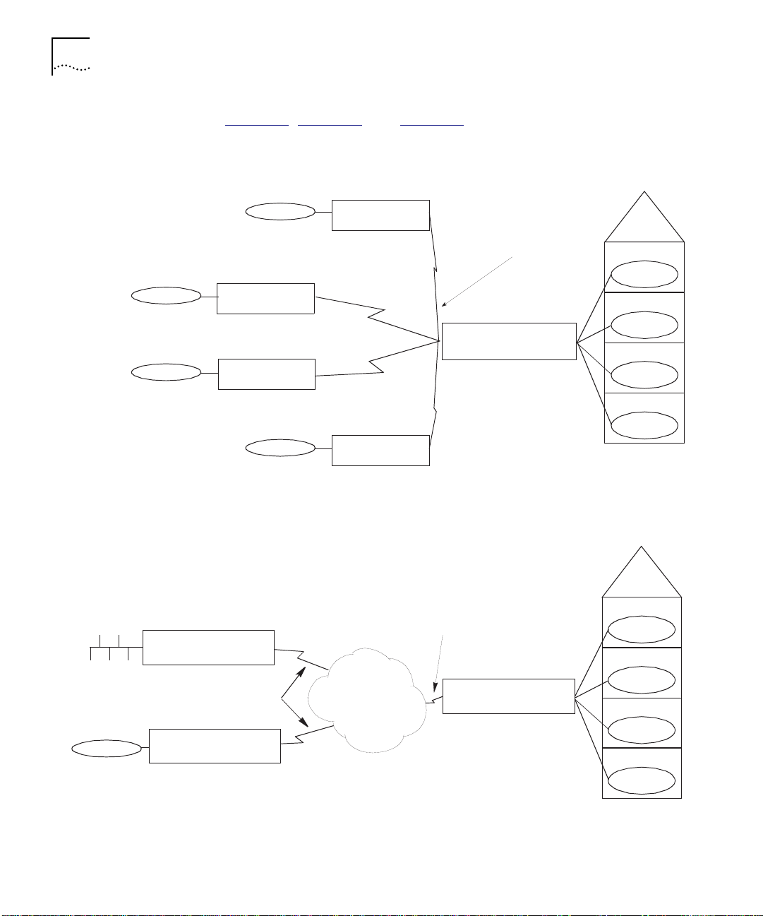
Typical Applications Figure 1-2, Figure 1-3, and Figure 1-4 show typical applications of the
Quad Serial, ATM OC3, and FDDI router modules.
Remote site C
Remote site D
Remote site B
3Com Edge
Router Module
3Co m Edge
Router Modu le
3Com Edge
Router Module
Remote site E
3Co m Edge
Router Module
Dedicated or dial-up
synchronous serial
connections
CoreBuilder 5000
Network Router Module
Figure 1-2 Quad Serial Network Router Module Typical Application
Local site A
Local site A
4th flo or
3rd floor
2nd flo or
1st floor
Ethernet
Token Ring
CoreBuilder 5 000
Network Router Module
ATM OC-3 MM
CoreBuilder 5000
Network Router Module
Figure 1-3 ATM OC3 Network Router Module Typical Application
ATM Service
ATM OC-3 MM
CoreBuilder 5000
Network Router Module
4th floor
3rd floor
2nd floor
1st floor
Build in g B
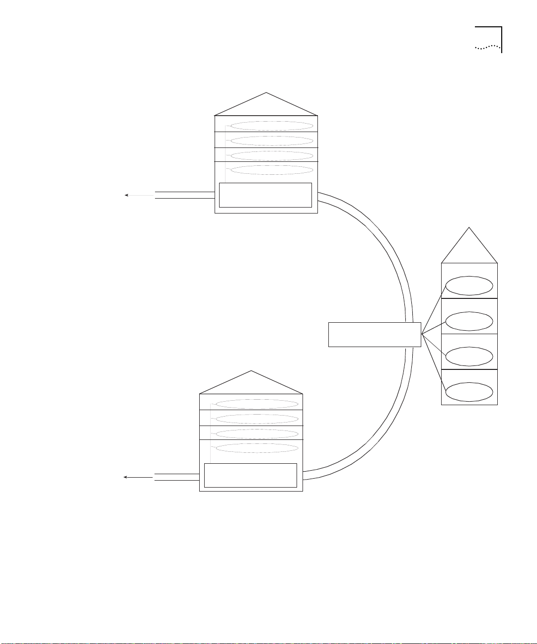
Router Module Overview 1-5
To other sites
To other sites
CoreBuild er 5000
Network Router Module
FDDI campus backbone
dual-attachment, multi-mode or single mode
Building C
CoreBuilder 5000
Networ k Rou ter Mod ul e
CoreBuilder 5000
Network Router Module
Buildin g A
4th floor
3rd floor
2nd floor
1st floor
Figure 1-4 Dual Attachment FDDI Network Router Module Typical Application

1-6 CHAPTER 1: INTRODUCTION
Router Module Features
FDDI Support The router module provides support for three FDDI configurations on
This section describes the following features of the router module:
■ FDDI Support
■ WAN Support
■ Protocol Translation
■ Scalable Protocol Support
■ WAN Optimization
■ ATM Migration
■ Management Support
■ Distributed, Scalable Reliability
■ Hot Swap Capability
the following two FDDI interfaces:
Multi-Mode Fiber – Can support distances of up to 2 km for both
Class A Dual Attachment Stations (DAS) and Class B Single
Attachment Stations (SAS).
Single Mode Fiber – Can support distances of up to 10 km for
Class A Dual Attachment Stations (DAS).
The FDDI interfaces also include a connector for attachment to an
external optical bypass unit. If the router module stops operating, the
optical bypass unit ensures that the FDDI signal bypasses that router.
The FDDI ring and other stations remain operational.
WAN Support The router module configured with a Quad Serial NIM provides four
synchronous serial ports to support backbone or redundant network
connections over the wide area network (WAN). The serial ports
support the following connection protocols:
■ V.35
■ EIA-232
■ EIA-449
■ RS-422
■ X.21

Router Module Features 1-7
Each serial port is capable of providing T1/E1 rate connectivity. Each
port operates in full duplex mode at speeds from 1,200 bits per
second (bps) to 2,048 Megabits per second (Mbps).
You can configure the synchronous serial ports to support IBM
®
Synchronous Data Link Control (SDLC) traffic using synchronous pass
through or Data Link Switching (DLSw).
Protocol Translation The router module protocol translation function allows you to extend
the life of your existing network devices. The router module allows
networks operating in dissimilar protocol environments to communicate
while managing up to 180 simultaneous sessions.
The router module supports the following bidirectional translations:
■ X.25 to TCP
■ X.25 to Local Area Transport (LAT)
■ X.25 to XRemote devices
■ LAT to TCP
■ LAT to TN3270 devices
Scalable Protocol
Support
Each router module type allows you to select a specific level of protocol
support to best match the needs of your application. Four Cisco IOS
router software feature sets offer an increasing level of protocol
support:
IP/IPX – The base feature set is used in applications requiring only
IP/IPX protocols.
Desktop – Provides additional LAN support for use in applications with
limited LAN protocol requirements.
Desktop plus IBM – Adds IBM support.
Enterprise – Adds top-level protocol support, including SNA
(Synchronous Network Architecture) integration.

1-8 CHAPTER 1: INTRODUCTION
Table 1-1 details the specific protocol support offered in each feature
set.
®
IPX
IP, Bridging,
LAN Extension,
Host Software,
Novell IPX,
DECnet
™
Appletalk
Phase 1 and 2
™
IV,
®
IP, Bridging, LAN
Extension, Host
Software, Novell IPX,
DECnet IV,
AppleTalk Phase 1
and 2
IP, Bridging, LAN
Extension, Host
Software, Novell IPX,
DECnet IV, AppleTalk
Phase 1 and 2, DECnet
V, XNS, Banyan
VINES
Table 1-1 Software Feature Sets
Feature
Category
Features Included in Each Feature Set
IP/IPX Desktop Desktop plus IBM Enterprise
LAN Support IP, Bridging,
LAN
Extension,
Host
Software,
Novell
Domain
IBM Support SRB/RSRB, SRT,
DLSW+, SNA &
NETBIOS
™
WAN
optimization (with
local
acknowledgment,
caching, and
filtering), SDLC
integration,
SDLC-to-LAN
conversion, SDLC
Transport (STUN),
Frame Relay SNA
Support (RFC 1490)
SRB/RSRB, SRT,
DLSW+, SNA &
NETBIOS WAN
optimization (with
local acknowledgment,
caching, and filtering),
SDLC integration,
SDLC-to-LAN
conversion, SDLC
Transport (STUN),
Frame Relay SNA
Support
(RFC 1490)TG/COS,
QLLC, DSPU
Concentration
Protocol
Translation
X.25-to-TCP,
X.25-to-LAT, and
X.25-to-XRemote;
LAT-to-TCP and
LAT-to-TN3279
(bidirectional)
IP Routing RIP, OSPF,
PIM, NHRP
RIP, OSPF, PIM,
NHRP, BGP,
EGP, IGRP
™
RIP, OSPF, PIM,
NHRP, BGP, EGP,
IGRP, Enhanced IGRP
RIP, OSPF, PIM, NHRP,
BGP, EGP, IGRP,
Enhanced IGRP, ES-IS,
IS-IS
WAN Services HDLC, PPP, X.25, Frame Relay, ISDN, SMDS, IPXWAN 2.0, ATM
WAN
Optimization
Header and link compression, X.25 packet payload compression,
dial-on-demand, dial backup, bandwidth-on-demand, custom and priority
queuing, access lists, access security, snapshot routing
Network
Autoinstall, SNMP, TELNET
Management
®
®
, OSI, Apollo®

Router Module Features 1-9
WAN Optimization The router module provides the following features to help limit network
operating costs by optimizing WAN network connections:
Dial-On-Demand Routing – A more economical alternative to a
second leased line as backup, a dial-on-demand backup dials up a
second line automatically if the primary WAN link fails.
Data Compression – The router module provides four types of data
compression for different network environments:
■ Link compression
■ X.25 packet payload compression
■ TCP/IP header compression
■ DEC
™
LAT compression
ATM Migration The router module can be upgraded to support your migration to an
ATM backbone (see Figure 1-3
).
Add an ATM network backbone by replacing your original router
module NIM, with one of two ATM NIM types:
Management
Support
■ OC-3, MM (Optical Carrier Type 3, Multi-Mode)
■ OC-3, SM (Optical Carrier Type 3, Single Mode)
Each ATM NIM type provides 155 Mbps backbone bandwidth.
The router module is shipped with a comprehensive Management
Information Base (MIB) for using Simple Network Management Protocol
(SNMP), the industry standard for network management.
You can monitor and control the router module from any SNMP-based
management station, including the 3Com Transcend Enterprise
Manager.
In addition, the router module is fully compatible with CiscoWorks
®
network management software from Cisco Systems.
TELNET capability provides for direct access in-band to the agent, and a
console port on the module provides for out-of-band management
capability.

1-10 CHAPTER 1: INTRODUCTION
Distributed, Scalable
Reliability
The router module operates in the CoreBuilder 5000 Integrated System
which is structured to eliminate any single point of failure.
The CoreBuilder 5000 hub provides redundancy for power supplies,
switched ports, controller modules, and the hub management module.
Automatic switching to the redundant components ensures
continuation of the specific function.
3Com fault-tolerant features are fully-scalable, allowing you to
implement and alter the degree of fault-tolerance you need as your
network grows.
Hot Swap Capability The router module features “hot swap” capability. You can swap the
router module in or out of (install or remove from) a powered-on
CoreBuilder 5000 hub.
2
INSTALLING THE MODULE
This chapter contains the following sections:
■ Precautionary Procedures
■ Quick Installation
■ Unpacking Procedures
■ Preparing to Install the Router Module
■ Installing the Router Module
■ Making NIM Connections
Precautionary Procedures
CAUTION: Electrostatic discharge (ESD) can damage static-sensitive
devices on circuit boards.
Follow these precautions when you unpack or handle the router
module:
■ Do not remove the board from its antistatic shielding bag until you
are ready to inspect or install it.
■ Handle the board by the faceplate only.
Use proper grounding techniques when you install the module,
including:
■ Using a footstrap and grounded static mat or wearing a grounded
static discharge wrist strap.
■ Touching the rack or other ground source just before you handle the
module.

2-2 CHAPTER 2: INSTALLING THE MODULE
Quick Installation Table 2-1 outlines the steps for quick installation of the
CoreBuilder
installing CoreBuilder 5000 modules, use this table as a checklist.
Otherwise, refer to the remainder of this chapter and to Chapters 3
and 4 to complete the installation.
.
Table 2-1 Quick Installation Steps
Step Procedure Section Title/Page Number
1 Unpack the module. Unpacking Procedures on
2 Prepare to install the module by verifying
3 Install the module into three contiguous
4 Connect the NIM cables. Making NIM Connections on
5 Attach a terminal to the console or auxiliary
6 Configure the NIM connections using Cisco
7 Configure the Cisco router interfaces using
8 Configure the Token Ring backplane
9 Monitor initial router module operation. Monitoring Router Module
™
5000 Network Router Module. If you are familiar with
DIP switch and jumper plug positions.
slots in the CoreBuilder 5000 Integrated
System Hub.
ports.
IOS router configuration commands.
Cisco IOS router configuration commands.
connections using DMM software.
page 2-2
Preparing to Install the Router
Module on page 2-4
Installing the Router Module
on page 2-5
page 2-7
Attaching a Management
Terminal on page 3-2
Configuring the Cisco NIM
Connections on page 3-3
Configuring Cisco
Parameters on page 3-3
Configuring 3Com
Parameters on page 3-5
LEDs on page 4-1
Unpacking Procedures
For information about potential problems, refer to the troubleshooting
techniques described in Chapter 5, Troubleshooting
.
To unpack the CoreBuilder 5000 Network Router Module:
1 Verify that the module is the model you ordered by checking the model
number listed on the side of the shipping carton.
The product model number listed on the box contains the prefix “3C9.”
Unpacking Procedures 2-3
2 Remove the module, in its antistatic bag, from the shipping carton.
3 Remove the module from the antistatic shielding bag and inspect it for
damage.
CAUTION: Always handle the module by the faceplate, being careful
not to touch the components. If the module appears to be damaged,
return it to the antistatic shielding bag, repack it in the shipping carton,
and contact your local supplier.
Keep the shipping carton and the antistatic shielding bag in which your
module was shipped so that you can repackage the module for storage
or shipment.
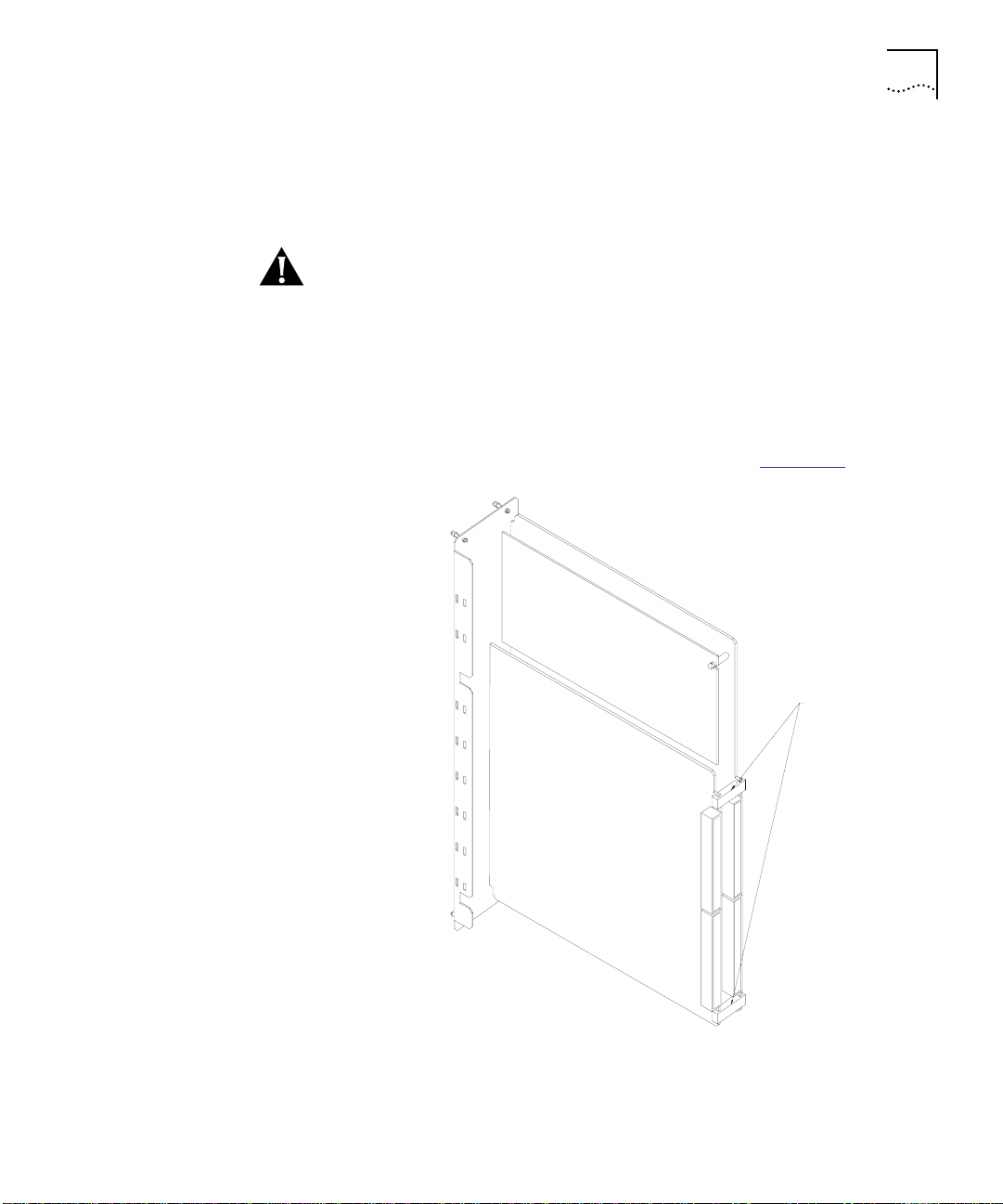
4 Remove the spacing clips from the router module (Figure 2-1
Spacing clips
).
Figure 2-1 Locating the Spacing Clips
2-4 CHAPTER 2: INSTALLING THE MODULE
CAUTION: The spacing clips on the CoreBuilder 5000 Network Router
Module are used only to protect the module during shipping. You must
manually remove the spacing clips before you install the module.
Failure to remove the spacing clips before installation could result in
damage to the CoreBuilder 5000 Integrated System Hub.
Preparing to Install the Router Module
Restoring Base
Board Positions
Plug inserted
in bottom
position
All DIP switch
positions on
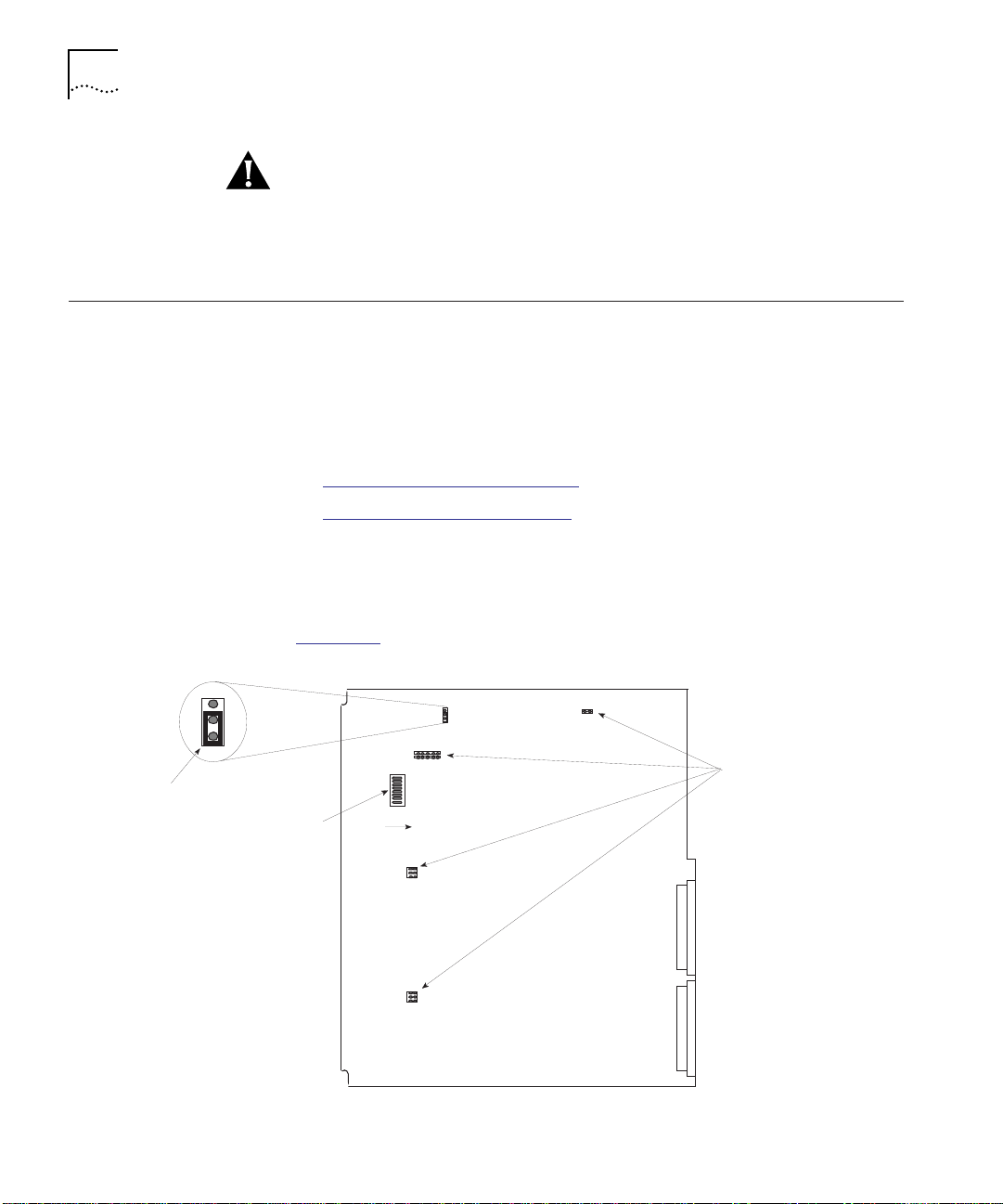
This section includes information to allow you to restore correct DIP
switch and jumper plug positions on the base and CPU boards if the
positions are inadvertently altered.
If you believe the default positions have been altered, refer to the
following sections:
■ Restoring Base Board Positions
■ Verifying CPU Board Positions
Do not attempt to configure the DIP switches and jumper plugs on the
base board. However, if you suspect that the DIP switch or jumper plug
positions have been altered, restore them to the positions shown in
Figure 2-2
.
.
Jumper plug
positions empty
On
Figure 2-2 Base Board DIP Switch and Jumper Plug Positions

Installing the Router Module 2-5
Verifying CPU Board
Positions
Do not attempt to configure the jumper plugs on the CPU board.
However, if you suspect that the jumper plug positions have been
altered, restore them to the positions shown in Figure 2-3
.
Plugs not inserted
Plug inserted in
bottom positi on
Figure 2-3 CPU Board Jumper Plug Positions
Plug inserted
.
Installing the Router Module
This section describes how to install the router module in the
CoreBuilder 5000 Integrated System Hub.
You do not need to power off the hub to install
or remove the router
module. You can insert the module while the hub is operating
(hot swap capability).
To install the router module:
1 Properly ground yourself prior to handling the module.
Put on a static wrist guard or touch a grounded static mat before you
handle the module.
2 Locate 3 adjacent open slots in the hub, or remove panels on the hub
to expose 3 slots for the router module.

2-6 CHAPTER 2: INSTALLING THE MODULE
3 Insert the router module into the board guides at the top and bottom
of the slot and slide it into the hub by pressing firmly at the top and
bottom of the faceplate. Make sure that the module ejectors are open
fully when you insert the module and that the connectors are
well-seated into the backplane of the hub. Figure 2-4
module being installed in a CoreBuilder 5000 Integrated System Hub.
Spring-lo aded screws
Ejector (opened)
CoreBuilder 5000 Network
Router Module
shows a router
Ejector
Spring-loaded screws
Figure 2-4 CoreBuilder 5000 Network Router Module in a CoreBuilder 5000
Integrated System Hub
To minimize electromagnetic interference, ensure that the slots adjacent
to the router module are occupied or have blank panels installed.
4 Push the module ejectors closed.
5 Using your fingers, tighten the spring-loaded screws on the front of the
router module faceplate (do not overtighten).

Making NIM Connections 2-7
Making NIM Connections
Making FDDI NIM
Connections
This section provides guidelines for making NIM (Network Interface
Module) network cable connections. This section describes the
following topics:
■ Making FDDI NIM Connections
■ Making Quad Serial NIM Connections
■ Making ATM NIM Connections
This section provides information on the following topics:
■ Connecting the Multi-Mode, Dual Attachment Station NIM
■ Connecting the Multi-Mode, Single Attachment Station NIM
■ Connecting the Multi-Mode Optical Bypass Switch
■ Connecting the Single Mode, Dual Attachment Station NIM
Connecting the Multi-Mode, Dual Attachment Station NIM
The Multi-Mode, Dual Attachment Station NIM (MM, DAS) connectors
are Fiber Distributed Data Interface (FDDI) standard physical sublayer
(PHY) connectors. The media interface connector (MIC) connects to
FDDI-standard 62.5/125 micron multi-mode fiber optic cable.
Figure 2-5
shows the MIC connector typically used for network and
chassis connections in multi-mode FDDI applications.
H1738
Figure 2-5 Multi-Mode FDDI Network Interface Connector, MIC Type
A dual attachment station requires two connections, one to the primary
ring and one to the secondary ring. On the FDDI MM, DAS NIM, the
PHY-A port is the left port and PHY-B is the right port.
Figure 2-6
shows how to connect a FDDI MM, DAS router module to
another Dual Attachment Station.

2-8 CHAPTER 2: INSTALLING THE MODULE
Figure 2-6 Making Connections to the FDDI MM, DAS NIM
To connect the FDDI MM, DAS NIM to another Dual Attachment
Station:
1 Connect PHY-A on the router module to PHY-B on the other DAS.
PHY-BPHY-A
PHY-B
Dual Attachment
Station (DAS)
PHY-A
2 Connect PHY-B on the router module to PHY-A on the other DAS.
Connecting the Multi-Mode, Single Attachment Station NIM
Connect the Single Attachment router module’s PHY-A port through a
concentrator to a Single Attachment ring (Figure 2-7
PHY-A
To concentrator
Figure 2-7 Making Connections to the FDDI MM, SAS NIM
).

Making NIM Connections 2-9
You can also connect the FDDI MM, SAS router module directly to
another device in a point-to-point configuration.
Connecting the Multi-Mode Optical Bypass Switch
The Multi-Mode FDDI router modules provide an optical bypass
capability that automatically drops the router module from the FDDI
ring if the module fails. Dropping the module from the ring ensures
that the ring remains available to the other stations.
To ring
Bypass operation
Figure 2-8
shows how to connect an optical bypass switch (not
included with the CoreBuilder 5000 Network Router Module) to the
FDDI MM, DAS NIM.
Optical bypass switch
Figure 2-8 Connecting the Multi-Mode Optical Bypass Switch
Optical bypass
interface cable
DIN
connector
To connect the FDDI MM, DAS NIM to an optical bypass switch:
1 Connect PHY-A on the router module to PHY-B on the optical bypass
switch.
2 Connect PHY-B on the router module to PHY-A on the optical bypass
switch.
3 Connect one end of the optical bypass interface cable to the 6-pin
Deutsche Industrie-Norm (DIN) connector on the optical bypass switch.
4 Connect the other end of the optical bypass interface cable to the
6-pin DIN connector on the router module.

2-10 CHAPTER 2: INSTALLING THE MODULE
Connecting the Single Mode, Dual Attachment Station NIM
A dual attachment, single mode module configuration requires two
connections: one to the primary ring and one to the secondary ring.
Figure 2-9
shows how to connect a FDDI SM, DAS router module to
another Dual Attachment Station.
FC connector type
To primary ring
To secondary ring
From primary ring
From secondary ring
Figure 2-9 Making Connections to the FDDI SM, DAS NIM
To connect the FDDI SM, DAS NIM to another Dual Attachment Station:
1 Connect one end of an FC connector cable to the PHY-A XMTR
connector on the router module.
2 Connect the other end of the FC connector cable to the primary ring
RCVR connector on the other DAS.
3 Connect one end of a second FC connector cable to the PHY-A RCVR
connector on the router module.
4 Connect the other end of the second FC connector cable to the
primary ring XMTR connector on the other DAS.
5 Connect one end of a third FC connector cable to the PHY-B XMTR
connector on the router module.
6 Connect the other end of the third FC connector cable to the
secondary ring RCVR connector on the other DAS.
7 Connect one end of a fourth FC connector cable to the PHY-B RCVR
connector on the router module.
8 Connect the other end of the fourth FC connector cable to the
secondary ring XMTR connector on the other DAS.

Making NIM Connections 2-11
Making Quad Serial
NIM Connections
The Quad Serial NIM has four synchronous serial ports with custom
DB-60 connectors.
When setting up your serial port connections, consider distance
limitations and potential electromagnetic interference (EMI) as defined
in the Electronics Industries Association (EIA) and Telecommunications
Industry Association (TIA) standards, such as standard EIA/TIA-232.
Figure 2-10
shows how to connect the Quad Serial NIM from any one
serial port on the router module to a modem or other communications
device.
Serial transmission cable
EIA/TIA-232, EIA/TIA-449, V.35,
X.21 or EIA-530 Connector
Modem or other
communications
device
Custom 60-pin
connector
Figure 2-10 Making Connections to the Quad Serial NIM
Be careful to insert the DB-60 connector correctly to prevent damage
to the connector pins.
To connect the Quad Serial NIM, attach each serial port from the
custom 60-pin connector to a modem or other DCE device using one
of the following standard device cable connectors:
■ EIA/TIA-232
■ EIA/TIA-449
■ EIA-530
■ V.35
■ X.21

2-12 CHAPTER 2: INSTALLING THE MODULE
Making ATM NIM
Connections
This section provides information on the following topics:
■ ATM Connector Types
■ ATM Distance Limitations
ATM Connector Types
Each ATM NIM type requires a specific connector (Figure 2-11
OC-3 MM NIM – Requires a multi-mode SC-type connector.
OC-3 SM NIM – Requires a single mode SC-type connector.
SC-type connector for
ATM OC-3 SM NIM
SC-type connector for
ATM OC-3 MM NIM
):
Figure 2-11 Making Connections to the ATM NIMs
ATM Distance Limitations
The SONET (Synchronous Optical Network) specification for fiber-optic
transmission defines two types of fiber:
■ single mode
■ multimode
Single-mode fiber is capable of higher bandwidth and greater cable run
distances than multimode fiber.

Making NIM Connections 2-13
The typical maximum distances for single-mode and multimode
transmissions, as defined by the SONET, are provided in Tab le 2 -2
you connect two optical devices at a distance greater than those
specified in Table 2-2
, significant signal loss could occur, making
transmission unreliable.
Table 2-2 ATM Distance Limitations
Fiber Type Maximum Distance Between Stations
Single mode Up to 9 miles (15 kilometers)
Multimode Up to 1.5 miles (3 kilometers)
. If


3
CONFIGURING THE MODULE
This chapter contains the following topics:
■ Configuration Overview
■ Attaching a Management Terminal
■ Configuring the Cisco NIM Connections
■ Configuring Cisco Parameters
■ Configuring 3Com Parameters
CAUTION: Throughout this chapter, Cisco nomenclature refers to the
four Token Ring backplane connections as interfaces 0, 1, 2, and 3.
3Com refers to the same four router connections as ports 1, 2, 3, and
4. For example, when configuring the router module, Cisco interface 0
is equivalent to 3Com port 1.
Configuration Overview
The following list is an overview of the procedures that are required
configure the router module. For more detail, refer to sections that
follow.
CAUTION: Failure to follow the configuration sequence specified in this
section could result in error messages at the router management
terminal during the configuration procedure. For best results, use the
procedure as outlined in the sections that follow.
To configure the router module:
1 Attach a Management Terminal – Attach a management terminal to
the console port of the router module.
2 Configure the Cisco NIM Connections – From the management
terminal, use Cisco router configuration commands to configure the
NIM (Network Interface Module) connections.

3-2 CHAPTER 3: CONFIGURING THE MODULE
3 Configure the Cisco Parameters – Use the management terminal to
configure the four Cisco router interfaces, including interface speed.
Attaching a Management Terminal
4 Configure the 3Com Parameters – Use the management terminal
that is connected to the 3Com
®
CoreBuilder 5000 Distributed
Management Module (DMM) to configure the four 3Com router ports,
including CoreBuilder
™
5000 backplane network speed.
Each of these steps is detailed in the sections that follow.
If you are using the router module in an unmanaged hub (one in which
a DMM module is not installed), upon power on, the router module
uses the last module configuration saved in NVRAM. To disable NVRAM
configuration, set DIP switch 5 to Off (see Figure 2-2
).
When you power on the router module with NVRAM configuration
disabled, the four Token Ring ports are set to isolated mode.
This section provides information on attaching a terminal to the console
or auxiliary ports of the router module for use as a Cisco management
terminal.
You must use the console port for initial router configuration. After you
configure the router, you can use the auxiliary port for an asynchronous
serial connection.
Connecting to the
Console Port
All router modules include an asynchronous router console port (female
DB-25 connector) wired as a data communications equipment (DCE)
device. The port requires a straight-through cable for connection to a
local terminal. The port uses the following default parameters:
■ 9600 baud
■ 8 data bits
■ No parity generated or checked
■ 2 stop bits

Configuring the Cisco NIM Connections 3-3
Connecting to the
Auxiliary Port
Configuring the Cisco NIM Connections
All router modules include a male DB-25 connector auxiliary port
(labeled AUX PORT DTE). The auxiliary port is a shared-memory data
terminal equipment (DTE) port to which you can attach an EIA/TIA-232
connector from a channel service unit/data service unit (CSU/DSU), a
modem, or protocol analyzer for network access.
Console and auxiliary port cabling requirements are provided in
Appendix B, Cabling Specifications
.
From the Cisco management terminal, use Cisco IOS routing
configuration commands to configure the FDDI or Quad Serial NIM
connections.
If you are configuring a base router module without a NIM installed
(Model Number 6701CS-NN), proceed to the next section Configuring
Cisco Parameters.
You may receive status messages referring to NIM 1, NIM 2, and NIM 3.
Cisco IOS makes the following NIM designations:
■ Optional NIM as NIM 1
■ Token Ring backplane interfaces 0 and 1 (3Com ports 1 and 2) as
NIM 2
Configuring Cisco Parameters
■ Token Ring backplane interfaces 2 and 3 (3Com ports 3 and 4) as
NIM 3
For detailed information on Cisco IOS routing configuration commands,
refer to the Cisco hardcopy documentation set
(Part Number 17-00138-MS) or to the Cisco documentation set on the
Cisco UniverCD
™
CD-ROM (Part Number 17-00138-CD).
This section outlines procedures for configuring Cisco parameters for
the four Token Ring interface connections on the router module using
Cisco IOS software management commands. The procedures include:
■ Setting General Interface Parameters
■ Setting Token Ring Speed

3-4 CHAPTER 3: CONFIGURING THE MODULE
Setting General
Interface Parameters
Setting Token Ring
Speed
Set any required general Cisco parameters for the four router
interfaces. Cisco Systems IOS software provides management
commands for configuring routing interface connections. Refer to the
Cisco hardcopy documentation set (Part Number 17-00138-MS) or to
the Cisco documentation set on the Cisco UniverCD CD-ROM
(Part Number 17-00138-CD).
Set the Token Ring speed of each router interface connection to match
the speed of the CoreBuilder 5000 backplane network to which it will
be connected.
To set the Token Ring speed of a router interface:
1 Use DMM at the CoreBuilder 5000 management station to ensure that
the router interface port is in isolated mode:
CB50 00> set po rt 7.1 network iso lated
Port 07 .01 networ k id set to I SOLATED.
2 At the router management terminal, set the configuration mode to
enable:
Rout er> e nable
3 Enter the required password:
Passwo rd: ****
4 Set the router management terminal to configuration mode:
Rout er# con fig termin al
Enter c onfigurat ion command s, one per line. End with
CNTL/Z.
Router (config)#
5 Specify the number of the Token Ring interface:
Router (co nfig )# in terface tokenrin g 0
Router (config-i f)#
6 Shut down the router interface:
Router (co nfig -i f)# shutdown
Router (config -if)#
7 Specify the ring speed of the router interface (in this example, 4 MBPS):
Router (co nfig -i f) # ring-speed 4
Router (config -if)#

Configuring 3Com Parameters 3-5
8 Remove the router interface from shutdown state:
Router (conf ig-i f)# no shutdown
Router (config -if)#
9 Exit from configuration mode:
Rout er(conf ig-i f)# ^Z
Rout er#
10 Save the interface configuration changes:
Rout er# w rite mem
Building configuration...
[OK]
Router#
At this point, the system may display a sequence of RESET messages on
the router management terminal. This a normal, temporary condition
that ends when the interface synchronizes to the new speed.
Configuring 3Com Parameters
This section outlines procedures for using DMM commands to
configure basic parameters for the 3Com router module.
Refer to the 3Com CoreBuilder 5000 Integrated System Hub Installation
and Operation Guide, Chapter 1, for a CoreBuilder 5000 backplane
architecture description and to the 3Com DMM Commands Guide for
detailed information on DMM configuration commands.
To configure the 3Com router module:
1 Set the Token Ring speed of the targeted four CoreBuilder 5000
backplane networks.
You must set the Token Ring speed of a backplane network to match
the Token Ring speed of the Cisco interface you intend to connect to
the backplane network.
In the following example, Token Ring backplane network 9 is set to 4
Mbps, the same speed at which the Cisco interface port was set.
CB50 00> s et network token_ring toke n_ring_9 r ing_speed
4mbps
Value set to 4 MBPS.
2 Connect each of the router ports to one of the 10 CoreBuilder 5000
backplane networks (or set the port to isolated mode).

3-6 CHAPTER 3: CONFIGURING THE MODULE
You cannot set more than one router port to any one backplane
network.
In the following example, 3Com router port 1 (Cisco interface 0) is set
to backplane network 9:
CB50 00> set port 7.1 network token_ring_9
Port 07 .01 networ k id set to T OKEN_RING _9.
At this point, the system may display a sequence of RESET messages at
the Cisco router management terminal. This is a normal, temporary
condition that ends when the interface successfully connects to the
backplane network.
3 Save the configuration:
CB50 00> save all
Failure to save configuration settings may result in loss of
configuration data.

4
MONITORING OPERATION
This chapter contains the following topics:
■ Monitoring Router Module LEDs
■ Displaying the Router Module Configuration
Monitoring Router Module LEDs
This section identifies the front panel LEDs of the CoreBuilder™5000
Network Router Module:
■ Common Front Panel LEDs
■ FDDI NIM LEDs
■ Quad Serial NIM LEDs
■ ATM NIM LEDs

4-2 CHAPTER 4: MONITORING OPERATION
Common Front Panel
LEDs
The front panel LEDs of the base model (without NIM) router module
are common to all router module models. Figure 4-1
common front panel LEDs. Table 4-1
describes the LEDs.
shows the
Figure 4-1 Common Front Panel LEDs
RESET is a recessed pushbutton that is used to reset the router module
under certain conditions. Refer to Chapter 5, Troubleshooting
, for
more information on using the RESET button.

Monitoring Router Module LEDs 4-3
.
Table 4-1 Front Panel LED Definitions
LED Description Definition
MOD STATUS Module Status ON – Indicates that 3Com router software is
loaded and the router module is
operational.
OFF – Indicates that 3Com router software
is not operational.
NIM PRES NIM Present ON – Indicates that an optional NIM is
installed on the router module.
OFF – Indicates that an optional NIM is not
installed on the router module.
SYS RUN System Run ON – Indicates that Cisco IOS router
software is loaded and operational.
OFF – Indicates that Cisco IOS router
software is not loaded and operational.
LEDS NIM NIM 1 Data
Present
ON – Indicates that data traffic is present
on one or more of the interfaces on the
optional NIM.
OFF – Indicates that data traffic is not
present on any interfaces on the optional
NIM.
LEDS DTR A, B NIM 2 (Dual
Token Ring A
and B) Data
Present
ON – Indicates that data traffic is present
on one or both of Cisco interfaces 0 and 1
(3Com ports 1 and 2).
OFF – Indicates that data traffic is present
on one or both of Cisco interfaces 0 and 1
(3Com ports 1 and 2).
LEDS DTR C, D NIM 3(Dual
Token Ring C
and D) Data
Present
ON – Indicates that data traffic is present
on one or both of Cisco interfaces 2 and 3
(3Com ports 3 and 4).
OFF – Indicates that data traffic is present
on one or both of Cisco interfaces 2 and 3
(3Com ports 3 and 4).
HLTH NIM NIM 1 Healthy ON – Indicates that optional NIM 1 is
operational and line protocol for the NIM
interfaces is up.
OFF – Indicates that the optional NIM 1 is
not operational.
HLTH DTR A, B NIM 2 (Dual
Token Ring A
and B) Healthy
ON – Indicates that Cisco interfaces 0 and 1
(3Com ports 1 and 2) are operational and
line protocol for the interfaces is up.
OFF – Indicates that Cisco interfaces 0 and
1 (3Com ports 1 and 2) are not operational.

4-4 CHAPTER 4: MONITORING OPERATION
Table 4-1 Front Panel LED Definitions (continued)
LED Description Definition
HLTH DTR C, D NIM 3 (Dual
16 MBPS A Port 1 (Cisco
16 MBPS B Port 2 (Cisco
16 MBPS C Port 3(Cisco
16 MBPS D Port 4 (Cisco
RING A IN Port 1 (Cisco
RING B IN Port 2 (Cisco
Token Ring A
and B) Healthy
interface 0) set
to 16 Mbps
interface 1) set
to 16 Mbps
interface 2) set
to 16 Mbps
interface 3) set
to 16 Mbps
interface 0) in
Ring
interface 1) in
Ring
ON – Indicates that Cisco interfaces 2 and 3
(3Com ports 3 and 4) are operational and
line protocol for the interfaces is up.
OFF – Indicates that Cisco interfaces 2 and
3 (3Com ports 3 and 4) are not operational.
ON – Indicates that port 1 (Cisco interface
0) is set to 16 Mbps.
OFF – Indicates that port 1 (Cisco interface
0) is set to 4 Mbps or is not initialized.
ON – Indicates that port 2 (Cisco interface
1) is set to 16 Mbps.
OFF – Indicates that port 2 (Cisco interface
1) is set to 4 Mbps or is not initialized.
ON – Indicates that port 3 (Cisco interface
2) is set to 16 Mbps.
OFF – Indicates that port 3 (Cisco interface
2) is set to 4 Mbps or is not initialized.
ON – Indicates that port 4 (Cisco interface
3) is set to 16 Mbps.
OFF – Indicates that port 4 (Cisco interface
3) is set to 4 Mbps or is not initialized.
ON – Indicates that port 1 (Cisco interface
0) is connected or connecting to its assigned
backplane network, or is set to isolated
mode.
OFF – Indicates that port 1(Cisco interface
0) is not connected to its assigned
backplane network.
ON – Indicates that port 2 (Cisco interface
1) is connected or connecting to its assigned
backplane network, or is set to isolated
mode.
OFF – Indicates that port 2 (Cisco interface
1) is not connected to its assigned
backplane network.

Monitoring Router Module LEDs 4-5
Table 4-1 Front Panel LED Definitions (continued)
LED Description Definition
RING C IN Port 3 (Cisco
interface 2) in
Ring
RING D IN Port 4 (Cisco
interface 3) in
Ring
ON – Indicates that port 3 (Cisco interface
2) is connected or connecting to its assigned
backplane network, or is set to isolated
mode.
OFF – Indicates that port 3 (Cisco interface
2) is not connected to its assigned
backplane network.
ON – Indicates that port 4 (Cisco interface
3) is connected or connecting to its assigned
backplane network, or is set to isolated
mode.
OFF – Indicates that port 4 (Cisco interface
3) is not connected to its assigned
backplane network.

4-6 CHAPTER 4: MONITORING OPERATION
FDDI NIM LEDs In addition to the common front panel LEDs, the three FDDI router
module models also have the LEDs shown in Figure 4-2
PHY-A
RING OP
PHY-B
RING OP
:
FDDI MM, DAS
Router Module
FDDI MM, SAS
Router Module
FDDI SM, DAS
Router M od ul e
Figure 4-2 FDDI NIM LEDs
The PHY-A RING OP LED lights when the router module PHY-A
attachment is connected in the FDDI A ring. The PHY-B RING OP LED
(Dual-Attachment FDDI NIMs only) lights when the PHY-B attachment
is connected in the FDDI B ring.

Monitoring Router Module LEDs 4-7
Quad Serial NIM
LEDs
The Quad Serial NIM router module model includes the additional LEDs
shown in Figure 4-3
P-3
P-2
P-1
P-0
.
LP
CN
TD
TC
RD
RC
LP
CN
TD
TC
RD
RC
LP
CN
TD
TC
RD
RC
LP
CN
TD
TC
RD
RC
Figure 4-3 Quad Serial NIM LEDs

4-8 CHAPTER 4: MONITORING OPERATION
Table 4-2 describes the Quad Serial NIM LEDs.
Table 4-2 Quad Serial NIM LED Definitions
LED Description Definition
LP Looped ON – Indicates that the port is set to a
CN Connected ON – Indicates that the port is in ready-state
TD Transmitted Data ON – Indicates that data is being
TC Transmitted Clock The clock supplied by the DCE device to
RD Received Data ON – Indicates that data is being received
RC Received Clock The clock supplied by the DCE device to
loopback state.
OFF – Indicates that the port is set to normal
mode.
(DSR, DTR, DCD, RTS, CTS signals) to
exchange data.
OFF – Indicates that the port is not in
ready-state to exchange data.
transmitted over the serial link from the DTE
device. The router module port can be set
to operate as DTE or DCE.
OFF – Indicates that data is not being
transmitted by the DTE device.
synchronize transmitted data.
over the serial link by the DCE device. Each
router module port can be set to operate as
DTE or DCE.
OFF – Indicates that data is not being
received by the DCE device.
synchronize received data.

Monitoring Router Module LEDs 4-9
ATM NIM LEDs The ATM MM and ATM SM router modules include the additional LEDs
shown in Figure 4-4
.
Figure 4-4 ATM NIM LEDs

4-10 CHAPTER 4: MONITORING OPERATION
Table 4-3 describes the ATM NIM LEDs.
Table 4-3 ATM NIM LED Definitions
LED Description Definition
Busy ATM NIM Busy ON – Indicates that the NIM is not available
Ready ATM NIM Ready ON – Indicates that the NIM is ready to
RX Cells Received Cells ON – Indicates that the ATM NIM is receiving
Rx Alarm Receive Alarm ON – Indicates that the receive signal is lost
to receive data cells.
OFF – Indicates that the NIM is available for
data cells.
receive data cells.
OFF – Indicates that the NIM is not ready to
receive ATM cells.
a a data cell. This LED flickers during normal
operation.
OFF – Indicates that the ATM NIM is not
receiving a data cell.
or that a remote alarm has been received by
the ATM NIM.
OFF – Indicates that the receive signal is not
lost and that a remote alarm has not been
received.
Displaying the Router Module Configuration
To display information about router module configuration and status,
use the following DMM commands.
■ SHOW MODULE
■ SHOW MODULE VERBOSE
■ SHOW PORT
■ SHOW PORT VERBOSE

Displaying the Router Module Configuration 4-11
A
Using the SHOW
MODULE Command
Slot Module Version Network General Information
----- --------- ------ ------- ----- -------- - ---------- --------
07.01 6704R-TCS v1.00.0 PER_PORT Module up
Using the SHOW
MODULE VERBOSE
Command
Slot Module Versi on Ne twork Gener al Informa tion
----- - --------- ----- ----- -- ------------- --- --------- -------
07.01 6704R-TCS v1.00.0 PER_PORT Module up
Use the SHOW MODULE command to display summary information
about the router module:
CB50 00> s how module 7.1
This command displays the summary information shown in Figure 4-5.
Figure 4-5 SHOW MODULE Command Information
Use the SHOW MODULE VERBOSE command to display detailed
information about the router module:
CB50 00> s how module 7.1 ver bose
This command displays the detailed information shown in Figure 4-6.
6704R- TCS: CB500 0 Token Ring Back bone Rout er Module
Boot Ve rsion: v1.00
Native Software V ersion: 10.30
Native Boot Software V ersion: v5.20
Number Simple Por ts: 1
Networ k Interfac e Module Typ e: FDDI- SINGLE-MO DE-DUAL-AT T
Using the SHOW
PORT Command
Figure 4-6 SHOW MODULE VERBOSE Command Information
Use the SHOW PORT command to display summary information about
any of the four router module ports:
CB50 00> show port 7.2

4-12 CHAPTER 4: MONITORING OPERATION
This command displays the summary information shown in Figure 4-7.
Port Mo de Sta tus Netwo rk Genera l Informat ion
----- ------ -- ------ -------- ----- ---- -------- ---- --------------- ------
07.02 L OGICAL OKAY TOKEN _RING_2
Figure 4-7 SHOW PORT Command Information
Using the SHOW
PORT VERBOSE
Use the SHOW PORT VERBOSE command to display detailed
information about any one of the four router module ports:
Command
CB50 00> s how port 7.2 verbose
This command displays the detailed information shown in Figure 4-8.
Port Di splay for Module 6704R -TCS :
Port Mo de Stat us Network General Informat ion
----- - ------- -- -------- --------- -- -------- ------ -- --------------------
07.02 L OGICAL OKAY TOKEN_R ING_2
Port Co nnector: BACKP LANE
IP Address: 151.104.12.1
Subnetwork Mask: ff.ff.00.00
Default Gateway: 0.0.0.0
Station Address: 08-00-8f-00-00-01
Speed: 16 MBPS
Figure 4-8 SHOW PORT VERBOSE Command Information
The Speed field in Figure 4-8 identifies the speed for the Cisco interface
that corresponds to the 3Com port.

Displaying the Router Module Configuration 4-13
Interpreting the
SHOW PORT Status
Field
The SHOW PORT and SHOW PORT VERBOSE commands provide
standard DMM command configuration information with the exception
of the Status field. DMM SHOW PORT Status field definitions are
unique for the CoreBuilder 5000 Network Router Module. Table 4-4
lists the Status field definitions for ports on the CoreBuilder 5000
Network Router Module.
Table 4-4 SHOW PORT Status Field Definitions
Status Field Indication Definitions
NOT INSERTED The port is set to isolated mode.
CONNECTING The port is attempting to connect with the backplane
network.
OKAY The port is connected normally to the backplane
network.
SPEED MISMATCH The speed of the port (as set for the corresponding
LOST LOCK The 3Com port has lost synchronization with the
Cisco interface) does not match the speed of the
backplane network to which it is assigned.
corresponding Cisco interface.


5
TROUBLESHOOTING
Troubleshooting Startup Problems
This chapter provides hardware troubleshooting information to use if
the CoreBuilder
correctly. After reviewing the information in this chapter, if you cannot
correct the problem, contact your 3Com representative for further
assistance.
For IOS software-related troubleshooting information, refer to the
appropriate Cisco Systems manual. For information on interpreting
router module LEDs, refer to Chapter 4, Monitoring Operation.
This chapter contains the following sections:
■ Troubleshooting Startup Problems
■ Troubleshooting Network Connection Problems
■ Troubleshooting WAN Connection Problems
■ Correcting Operating Malfunctions
■ Recovering a Lost Password
This section describes how to troubleshoot startup problems on the
CoreBuilder 5000 Network Router Module.
™
5000 Network Router Module fails to operate
When you first install the router module in the hub, the Cisco Systems
router software runs a full set of hardware diagnostic tests. If the router
module fails diagnostics, the MOD STATUS LED does not turn off. This
indicates a problem with the router module hardware or software.
Refer to the appropriate Cisco Systems troubleshooting documentation
for corrective action.

5-2 CHAPTER 5: TROUBLESHOOTING
Troubleshooting Network Connection Problems
Troubleshooting WAN Connection Problems
If the CoreBuilder 5000 Network Router Module does not appear to be
routing traffic properly on the network, it may indicate that there is no
connection to the network. Perform the following troubleshooting
actions:
■ From the 3Com management interface (for example,
CoreBuilder 5000 Distributed Management Module), verify that the
router module backplane port is set to the appropriate backplane
network (channel).
■ Use the DMM SHOW PORT command and check the Status field for
the port. Refer to Using the SHOW PORT VERBOSE Command
on
page 4-12.
■ Use the ping utility to confirm there is network connectivity.
■ Verify that your router configuration is valid. Refer to the Cisco
Systems Troubleshooting Internetworking Systems guide for more
information.
If you suspect that the CoreBuilder 5000 Network Router Module has
lost WAN connectivity, perform the following troubleshooting actions:
■ Verify that you have the correct cable for your configuration. Refer
to Appendix B, Cabling Specifications, for lists of approved cables,
cable specifications, and pinouts.
■ If you are using a:
DCE cable – Verify that a clock rate is defined in the router WAN
interface configuration.
DTE cable – Verify that no clock rate is defined in the router WAN
interface configuration.
■ Verify that your router configuration is valid. Refer to the Cisco
Systems Troubleshooting Internetworking Systems guide for more
information.

Correcting Operating Malfunctions 5-3
Correcting Operating Malfunctions
Table 5-1 Troubleshooting Malfunctions
Table 5-1 lists the symptoms, possible causes and corrective actions of
operating malfunctions for the CoreBuilder 5000 Network Router
Module.
.
Symptom Possible Cause Corrective Action
Module does not
power up
Module is not fitted
correctly against
backplane.
To ensure that the module is fitted correctly,
remove the module from the slots and replace it
in the slots.
Place the module in different slots in the hub.
Power mode is not
Ensure that power mode is enabled for the slot.
enabled for slot.
The hub is not
receiving electrical
power.
Check that the hub is receiving power.
Test for power at the wall outlet by plugging in
another device.
If the wall outlet is not receiving power, select
another outlet on a different circuit.
Attached terminal does
not operate
The terminal is
malfunctioning.
Follow the troubleshooting procedures
recommended by the terminal manufacturer.
Cables are unattached. Make sure that the cable connections at both
ends are secure.
Cables are not the
correct type.
Make sure that the cable attached to the
terminal conforms to the specification. Refer to
Appendix B for cabling specifications.
The console is
configured incorrectly.
Check the console port configuration.
Note: You can use TELNET to verify port
configurations.
Refer to the Cisco Systems Router Products
Configuration and Reference documents for
more information. Verify that the port is
configured as:
■ 8-bit data
■ No parity
■ 2 stop bits
■ 9600 baud rate
■ Flow control parameters set to Xon and Xoff

5-4 CHAPTER 5: TROUBLESHOOTING
Table 5-1 Troubleshooting Malfunctions (continued)
Symptom Possible Cause Corrective Action
The terminal fails to
respond to commands
entered at the keyboard
The terminal is not
receiving commands.
The keyboard cable is
attached incorrectly.
Cables are not the
correct type.
The console port is
malfunctioning.
Power off the terminal, wait 30 seconds, and
then power on again.
If the terminal still does not respond to
commands, power off the terminal and
disconnect the keyboard cable. Then re-attach
the keyboard cable and power on the terminal.
Make sure that the cable attached to the
terminal conforms to the specification. Refer to
Appendix B
Check the state of the LEDs on the front of the
module. If the LEDs indicate a problem, contact
your supplier for assistance.
for cabling specifications.
Recovering a Lost Password
To recover a lost password:
1 Attach an ASCII terminal to the router module console port.
2 Configure the terminal to operate at 9600 baud, 8 data bits, no parity,
2 stop bits.
3 Enter the SHOW VERSION command to display the existing
configuration register value. Note this value for later use in step 13.
4 If the Break function is disabled on the router (refer to Ta bl e C- 1
),
power cycle the router (turn off the router, wait 5 seconds, and then
turn it on again). If the Break function is enabled, go to step 5.
5 Within 60 seconds of turning on the router, press the Break key.
Pressing this key causes the terminal to display the bootstrap program
prompt (>).
6 To reset the virtual configuration register (VCR) to boot from the boot
ROMs and ignore NVRAM, enter the O/R (Reset VCR Value) command
at the bootstrap prompt:
> o/r 0x2 141
To recover a lost password, you must be able to see it when you
display configuration information. To see the password, be sure to set
the configuration register so that the router module engine ignores
the contents of the NVRAM.

Recovering a Lost Password 5-5
7 Initialize the router by entering the I (Initialize) command as follows:
> i
The router power cycles and the configuration register is set to 0x2141
(ignore Break key, ignore NVRAM, boot from ROM). The router boots
the boot ROM system image and prompts you with the following
system configuration dialog prompt:
--- Sys tem Configuration Dia log ---
8 Enter No in response to the system configuration dialog prompts until
the following system message appears:
Press R ETURN to get started!
9 Press Return. The boot ROM prompt appears as follows:
Router (boot )>
10 Enter the ENABLE command to enter the EXEC mode in the boot ROM
image. The prompt changes to the following:
Router (bo ot)#
11 Enter the SHOW CONFIGURATION EXEC command to display the
password in the configuration file and to display any boot system
commands.
12 To exit configuration mode, press Ctrl-Z.
13 Restore the virtual configuration register to the value noted in step 3.
Use the CONFIGURE TERMINAL command to restore the value:
rout er# configure terminal
Enter s ystem configuration comma nds, one per line.
Edit with DE LETE, CTRL /W, and CT RL/U; end with CTRL/Z
config -reg 0xYYYY
^Z
where Y YYY is the value noted in step 3
14 Reboot the router and use the recovered password.
Refer to Appendix C
for more information about the virtual
configuration register.


A
PRODUCT SPECIFICATIONS
This appendix contains the following hardware specifications for the
3Com CoreBuilder
■ General Specifications
■ Electrical Specifications
■ Environmental Specifications
■ Mechanical Specifications
™
5000 Network Router Module:

A-2 APPENDIX A: PRODUCT SPECIFICATIONS
General Specifications
Table A-1 identifies general specifications for the router module.
Table A-1 General Router Module Specifications
Specification Description
Processor 100 MHz IDT Orion RISC
Main Memory (DRAM) 8, 16, or 32 MB
Shared Memory (DRAM) 4, 8, or 16 MB
Flash Memory 4, 8 MB
Nonvolatile RAM 128 or 512 KB
Boot ROM 128 to 512 KB
Boot Flash 4 MB
Network Interface
Options
Token Ring Interface 4 backplane connection
Synchronous Serial
Interfaces
(Quad Serial NIM)
Console and Auxiliary
Ports
* The Orion microprocessor is based on the MIPS R4400 and is pin-compatible.
† NRZ = Nonreturn to zero. NRZI = Nonreturn to zero inverted.
‡ DTE = Data terminal equipment. DCE = Data communications equipment.
FDDI Multi-Mode, Dual Attachment Station
FDDI Multi-Mode, Single Attachment Station
FDDI Single Mode, Dual Attachment Station
Quad Serial
ATM OC3, Multi-Mode
ATM OC3, Single Mode
EIA/TIA-232, EIA/TIA-449, V.35, X.21 (NRZ/NRZI† and
DTE/DCE
cables use a DB-60 connector.
Asynchronous serial
‡
), EIA-530 (NRZ/NRZI and DTE). All serial
*

Electrical Specifications A-3
Electrical Specifications
Environmental Specifications
Table A-2 identifies the electrical specifications for the router module.
Table A-2 Electrical Router Module Specifications
Voltage Amps (Watts)
Power Requirements
(with NIM)
+5 VDC 19.0 A (95.0 W)
–5 VDC 0.05 A (0.25 W)
+12 VDC 0.5 A (6.0 W)
–12 VDC 0.08 A (1.0 W)
–2 VDC 0.05A (0.1 W)
(102.35 W Total)
Table A-3 identifies environmental specifications for the router module.
Table A-3 Environmental Router Module Specifications
Operating Temperature 0 °C to 50 °C (32 °F to 122 °F)
Storage Temperature -10 °C to 66 °C (22 °F to 138 °F)
Humidity Less than 95%, noncondensing
BTU/hr 349.31 BTUs/hr
Mechanical Specifications
Table A-4 identifies the mechanical specifications of the router module.
Table A-4 Mechanical Router Module Specifications
CoreBuilder 5000
Network Router Module
(with NIM)
Width 3.0” (7.62 cm)
Length 10.875” (27.623 cm)
Height 15.250” (38.735 cm)
Weight 8.5 lbs (3.859 kg)


B
CABLING SPECIFICATIONS
Use the information in this appendix to verify that the cables you use
meet equipment requirements. For proper operation, use only approved
cables when you install all equipment.
This appendix describes:
■ Console and Auxiliary Port Cables
■ Quad Serial NIM Cables
Console and Auxiliary Port Cables
This section specifies the cable pinouts of the console and auxiliary
ports of the CoreBuilder
any cable that meets the pinout specifications described in this section.
All pins not listed are not connected.
This section describes the following cabling specifications:
■ Console Port Pinouts
■ Auxiliary Port Pinouts
™
5000 Network Router Module. You can use

B-2 APPENDIX B: CABLING SPECIFICATIONS
Console Port Pinouts Table B-1 identifies the pinout specifications for the console port.
Table B-1 Console Port Pinout Specification
Pin Signal Name Input/Output
1 Frame GND —
2 Received Data Input
3 Transmitted Data Output
4 Request To Send Looped to Clear To Send
5 Clear To Send Looped to Request To Send
6 Connected to Pin 8 Output
7 Signal Ground —
8 Data Carrier Detect Output
20 Data Terminal Ready Input
Auxiliary Port
Pinouts
Table B-2
identifies the pinout specifications for the auxiliary port.
Table B-2 Auxiliary Port Pinout Specification
Pin Signal Name Input/Output
1 Frame GND —
2 Transmitted Data Output
3 Received Data Input
4 Request To Send Output
5 Clear To Send Input
7 Signal Ground —
8 Data Carrier Detect Input
20 Data Terminal Ready Output

Quad Serial NIM Cables B-3
Quad Serial NIM Cables
This section specifies cable pinouts for each type of synchronous serial
cable supported by the Quad Serial NIM (Network Interface Module) on
the CoreBuilder 5000 Network Router Module.
This section describes:
■ EIA-530 DTE Synchronous Serial Cable Pinouts
■ EIA-232 DTE and DCE Serial Cable Assembly and Pinouts (DB-25)
■ EIA-449 DTE and DCE Serial Cable Assembly and Pinouts (DB-37)
■ V.35 DTE and DCE Serial Cable Assembly and Pinouts
■ X.21 DTE and DCE Serial Cable Pinouts (DB-15)
In Table B-3 through Table B-11, serial pinouts for DTE and DCE cables
use arrows to indicate signal direction:
■ → indicates DTE to DCE
■ ← indicates DCE to DTE
Due to the small pins on the DB-60 connector, you should not attempt
to manufacture or solder these cables.

B-4 APPENDIX B: CABLING SPECIFICATIONS
EIA-530 DTE
Synchronous Serial
Cable Pinouts
Figure B-1
shows the EIA-530 serial cable assembly and Table B-3 lists
the cable pinouts (Part Number ERM530-CAB). Arrows in the table
indicate signal direction:
■ → indicates DTE to DCE
■ ← indicates DCE to DTE
J1-46
J1-45
J1-16
J1-15
J1-1
J1-30
J1-31
J1-60
Figure B-1 EIA-530 Cable Assembly
Table B-3 EIA-530 Cable Pinout Specifications
60 Pin1Signal 25 Pin1Signal
J1-46
J1-47
J1-48
J1-49
J1-11
J1-12
J1-28
J1-27
J1-9
J1-10
J1-1
J1-2
J1-3
J1-4
J1-5
J1-6
Shield_GND
MODE_2
GND
MODE_1
TxD/RxD+
TxD/RxD–
RxD/TxD+
RxD/TxD–
RTS/CTS+
RTS/CTS–
CTS/RTS+
CTS/RTS–
DSR/DTR+
DSR/DTR–
DCD/DCD+
DCD/DCD–
60-pin connector 25-pin connector
Connectors are not to scale
Direction
DTE DCE
J2-1
—
— — Shorted
J2-2
J2-14
J2-3
J2-16
J2-4
J2-19
J2-5
J2-13
J2-6
J2-22
J2-8
J2-10
Shield
—
BA(A), TxD+
BA(B), TxD-
BB(A), RxD+
BB(B), RxD-
CA(A), RTS+
CA(B), RTS-
CB(A), CTS+
CB(B), CTS-
CC(A), DSR+
CC(B), DSR-
CF(A), DCD+
CF(B), DCD-
Shorted
→
→
←
←
→
→
←
←
←
←
←
←
J2-13
J2-25
H1972
J2-14
J2-1
2

Quad Serial NIM Cables B-5
Table B-3 EIA-530 Cable Pinout Specifications (continued)
EIA-232 DTE and
DCE Serial Cable
Assembly and
Pinouts (DB-25)
Direction
60 Pin1Signal 25 Pin1Signal
J1-24
J1-23
J1-26
J1-25
J1-44
J1-45
J1-7
J1-8
J1-13
J1-14
J1-51
J1-52
1Any pin not referenced is not connected.
2 The EIA-530 interface cannot be operated in DCE mode. A DCE cable is not
available for the EIA-530 interface.
Figure B-2
TxC/RxC+
TxC/RxC–
RxC/TxCE+
RxC/TxCE–
LL/DCD
Circuit_GND
DTR/DSR+
DTR/DSR–
TxCE/TxC+
TxCE/TxC–
GND
J2-15
J2-12
J2-17
J2-9
J2-18
J2-7
J2-20
J2-23
J2-24
J2-11
DB(A), TxC+
DB(B), TxC-
DD(A), RxC+
DD(B), RxC-
LL
Circuit GND
CD(A), DTR+
CD(B), DTR-
DA(A), TxCE+
DA(B), TxCE-
— — Shorted
MODE_DCE
shows the EIA-232 serial cable assembly. Table B-4 lists the
DTE DCE
←
←
←
←
→
—
→
→
→
→
DTE cable pinouts (Part Number ERM232-CAB). Table B-5
2
lists the DCE
cable pinouts (Part Number ERF232-CAB). Arrows in the tables indicate
signal direction:
■ → indicates DTE to DCE
■ ← indicates DCE to DTE
J1-46
J1-45
J1-16
J1-15
J1-1
J1-30
J1-31
J1-60
60-pin connector 25-pin connector
Connectors are not to scale
Figure B-2 EIA-232 Serial Cable Assembly
J2-13
J2-25
H1972
J2-14
J2-1

B-6 APPENDIX B: CABLING SPECIFICATIONS
Table B-4 EIA-232 DTE Cable Pinouts (DB-60 to DB-25)
60 Pin1Signal Note Direction 25 Pin1Signal
J1-50
J1-51
J1-52
MODE_0
GND
MODE_DCE
Shorting Group — — —
J1-46 Shield_GND Single — J2-1 Shield GND
J1-41
Shield
J1-36
Shield
J1-42
Shield
J1-35
Shield
J1-34
Shield
J1-45
Shield
J1-33
Shield
J1-37
Shield
J1-38
Shield
J1-44
Shield
J1-43
Shield
J1-39
Shield
1
Any pin not referenced is not connected.
TxD/RxD
—
RxD/TxD
—
RTS/CTS
—
CTS/RTS
—
DSR/DTR
—
Twisted pair no. 5 →
—
Twisted pair no. 9 ←
—
Twisted pair no. 4 →
—
Twisted pair no. 10 ←
—
Twisted pair no. 11 ←
—
J2-2
Shield
J2-3
Shield
J2-4
Shield
J2-5
Shield
J2-6
Shield
Circuit GND Twisted pair no. 1 — J2-7
Shield
DCD/LL
—
TxC/NIL
—
RxC/TxCE
—
LL/DCD
—
DTR/DSR
—
TxCE/TxC
—
Twisted pair no. 12 ←
—
Twisted pair no. 8 ←
—
Twisted pair no. 7 ←
—
Twisted pair no. 2 →
—
Twisted pair no. 3 →
—
Twisted pair no. 6 →
—
J2-8
Shield
J2-15
Shield
J2-17
Shield
J2-18
Shield
J2-20
Shield
J2-24
Shield
TxD
—
RxD
—
RTS
—
CTS
–
DSR
—
Circuit GND
DCD
—
TxC
—
RxC
—
LTST
—
DTR
—
TxCE
—

Quad Serial NIM Cables B-7
Table B-5 EIA-232 DCE Cable Pinouts (DB-60 to DB-25)
60 Pin1Signal Note Direction 25 Pin1Signal
J1-50
J1-51
MODE_0
GND
Shorting Group — — —
J1-46 Shield_GND Single — J2-1 Shield GND
J1-36
Shield
J1-41
Shield
J1-35
Shield
J1-42
Shield
J1-43
Shield
J1-45
Shield
J1-44
Shield
J1-39
Shield
J1-40
Shield
J1-33
Shield
J1-34
Shield
J1-38
Shield
1 Any pin not referenced is not connected.
RxD/TxD
—
TxD/RxD
—
CTS/RTS
—
RTS/CTS
—
DTR/DSR
—
Circuit GND
—
LL/DCD
—
TxCE/TxC
—
NIL/RxC
—
DCD/LL
—
DSR/DTR
—
RxC/TxCE
—
Twisted pair no. 9 ←
—
Twisted pair no. 5 →
—
Twisted pair no. 10 ←
—
Twisted pair no. 4 →
—
Twisted pair no. 3 →
—
Twisted pair no. 1 —
—
Twisted pair no. 2 →
—
Twisted pair no. 7 →
—
Twisted pair no. 6 →
—
Twisted pair no. 12 ←
—
Twisted pair no. 11 ←
—
Twisted pair no. 8 ←
—
J2-2
Shield
J2-3
Shield
J2-4
Shield
J2-5
Shield
J2-6
Shield
J2-7
Shield
J2-8
Shield
J2-15
Shield
J2-17
Shield
J2-18
Shield
J2-20
Shield
J2-24
Shield
TxD
—
RxD
—
RTS
—
CTS
—
DSR
—
Circuit GND
DCD
—
TxC
—
RxC
—
LTST
—
DTR
—
TxCE
—

B-8 APPENDIX B: CABLING SPECIFICATIONS
EIA-449 DTE and
DCE Serial Cable
Assembly and
Pinouts (DB-37)
Figure B-3
shows the EIA-449 serial cable assembly. Table B-6 lists the
DTE cable pinouts (Part Number ERM449-CAB). Table B-7
cable pinouts (Part Number ERF449-CAB). Arrows in the tables indicate
signal direction:
■ → indicates DTE to DCE
■ ← indicates DCE to DTE
J1-46
J1-45
J1-16
J1-15
J1-1
J1-30
J1-31
J1-60
Figure B-3 EIA-449 Serial Cable Assembly
Table B-6 EIA-449 DTE Cable Pinouts (DB-60 to DB-37)
60-pin connector (J1)
Connectors are not to scale
lists the DCE
37-pin connector (J2)
J2-19
J2-37
H1973
J2-20
J2-1
60 Pin1Signal Note Direction 37 Pin1Signal
J1-49
J1-48
J1-51
J1-52
J1-46 Shield_GND Single — J2-1 Shield GND
J1-11
J1-12
J1-24
J1-23
J1-28
J1-27
J1-9
J1-10
J1-26
J1-25
MODE_1
GND
GND
MODE_DCE
TxD/RxD+
TxD/RxD–
TxC/RxC+
TxC/RxC–
RxD/TxD+
RxD/TxD–
RTS/CTS+
RTS/CTS–
RxC/TxCE+
RxC/TxCE–
Shorting Group — — —
Shorting Group — — —
Twisted pair no. 6
Twisted pair no. 9
Twisted pair no. 11
Twisted pair no. 5
Twisted pair no. 10
→
→
←
←
←
←
→
→
←
←
J2-4
J2-22
J2-5
J2-23
J2-6
J2-24
J2-7
J2-25
J2-8
J2-26
SD+
SD–
ST+
ST–
RD+
RD–
RS+
RS–
RT+
RT–

Quad Serial NIM Cables B-9
Table B-6 EIA-449 DTE Cable Pinouts (DB-60 to DB-37) (continued)
60 Pin1Signal Note Direction 37 Pin1Signal
J1-1
J1-2
J1-44
J1-45
J1-3
J1-4
J1-7
J1-8
J1-5
J1-6
J1-13
J1-14
J1-15
J1-16
1
Any pin not referenced is not connected.
CTS/RTS+
CTS/RTS–
LL/DCD
Circuit_GND
DSR/DTR+
DSR/DTR–
DTR/DSR+
DTR/DSR–
DCD/DCD+
DCD/DCD–
TxCE/TxC+
TxCE/TxC–
Circuit_GND
Circuit_GND
Twisted pair no. 1
←
←
Twisted pair no. 12 →
—
Twisted pair no. 2
←
←
Twisted pair no. 4
→
→
Twisted pair no. 3
←
←
Twisted pair no. 7
→
→
Twisted pair no. 9 —
—
J2-9
J2-27
J2-10
J2-37
J2-11
J2-29
J2-12
J2-30
J2-13
J2-31
J2-17
J2-35
J2-19
J2-20
CS+
CS–
LL
SC
DM+
DM–
TR+
TR–
RR+
RR–
TT+
TT–
SG
RC
Table B-7 EIA-449 DCE Cable Pinouts (DB-60 to DB-37)
60 Pin1Signal Note Direction 37 Pin1Signal
J1-49
J1-48
J1-46 Shield_GND Single — J2-1 Shield GND
J1-28
J1-27
J1-13
J1-14
J1-11
J1-12
J1-1
J1-2
J1-24
J1-23
J1-9
J1-10
J1-29
J1-30
MODE_1
GND
RxD/TxD+
RxD/TxD–
TxCE/TxC+
TxCE/TxC–
TxD/RxD+
TxD/RxD–
CTS/RTS+
CTS/RTS–
TxC/RxC+
TxC/RxC–
RTS/CTS+
RTS/CTS–
NIL/LL
Circuit_GND
Shorting group — — —
Twisted pair no. 11
←
←
Twisted pair no. 7
→
→
Twisted pair no. 6
→
→
Twisted pair no. 1
←
←
Twisted pair no. 9
→
→
Twisted pair no. 5
→
→
Twisted pair no. 12 →
—
J2-4
J2-22
J2-5
J2-23
J2-6
J2-24
J2-7
J2-25
J2-8
J2-26
J2-9
J2-27
J2-10
J2-37
SD+
SD–
ST+
ST–
RD+
RD–
RS+
RS–
RT+
RT–
CS+
CS–
LL
SC

B-10 APPENDIX B: CABLING SPECIFICATIONS
Table B-7 EIA-449 DCE Cable Pinouts (DB-60 to DB-37) (continued)
60 Pin1Signal Note Direction 37 Pin1Signal
J1-7
J1-8
J1-3
J1-4
J1-5
J1-6
J1-26
J1-25
J1-15
J1-16
1
Any pin not referenced is not connected.
DTR/DSR+
DTR/DSR–
DSR/DTR+
DSR/DTR–
DCD/DCD+
DCD/DCD–
RxC/TxCE+
RxC/TxCE–
Circuit_GND
Circuit_GND
Twisted pair no. 4
→
→
Twisted pair no. 2
←
←
Twisted pair no. 3
→
→
Twisted pair no. 10
←
←
Twisted pair no. 8 —
—
J2-11
J2-29
J2-12
J2-30
J2-13
J2-31
J2-17
J2-35
J2-19
J2-20
DM+
DM–
TR+
TR–
RR+
RR–
TT+
TT–
SG
RC
V.35 DTE and DCE
Serial Cable
Assembly and
Pinouts
Figure B-4
cable pinouts (Part Number ERMV35-CAB). Table B-9
shows the V.35 serial cable assembly. Table B-8 lists the DTE
lists the DCE cable
pinouts (Part Number ERFV35-CAB). Arrows in the tables indicate signal
direction:
■ → indicates DTE to DCE
■ ← indicates DCE to DTE
J1-46
J1-45
J1-16
J1-15
J1-1
J1-30
J1-31
J1-60
Connectors are not to scale
60-pin connector (J1)
Figure B-4 V.35 Serial Cable Assembly
15-pin connector (J2)
34
J2-B
J2-D
J2-A
J2-C
J2-KK
J2-MM
J2-LL
J2-NN
H1975

Quad Serial NIM Cables B-11
Table B-8 V.35 DTE Cable Pinouts (DB-60 to Winchester-Type 34-Pin)
60 Pin1Signal Note Direction 34 Pin1Signal
J1-49
J1-48
J1-50
J1-51
J1-52
J1-53
J1-54
J1-55
J1-56
J1-46 Shield_GND Single — J2-A Frame GND
J1-45
Shield
J1-42
Shield
J1-35
Shield
J1-34
Shield
J1-33
Shield
J1-43
Shield
J1-44
Shield
J1-18
J1-17
J1-28
J1-27
J1-20
J1-19
J1-26
J1-25
J1-24
J1-23
1 Any pin not referenced is not connected.
MODE_1
GND
MODE_0
GND
MODE_DCE
TxC/NIL
RxC_TxCE
RxD/TxD
GND
Circuit_GND
—
RTS/CTS
—
CTS/RTS
—
DSR/DTR
—
DCD/LL
—
DTR/DSR
—
LL/DCD
–—
TxD/RxD+
TxD/RxD–
RxD/TxD+
RxD/TxD–
TxCE/TxC+
TxCE/TxC–
RxC/TxCE+
RxC/TxCE–
TxC/RxC+
TxC/RxC–
Shorting Group — — —
Shorting Group — — —
Shorting Group — — —
Twisted pair no. 12 —
—
Twisted pair no. 9 →
Twisted pair no. 8 ←
Twisted pair no. 7 ←
Twisted pair no. 6 ←
Twisted pair no. 10 →
Twisted pair no. 11 →
Twisted pair no. 1
—
—
—
—
—
—
→
→
Twisted pair no. 5
←
←
Twisted pair no. 2
→
→
Twisted pair no. 4
←
←
Twisted pair no. 3
←
←
J2-B
Shield
J2-C
Shield
J2-D
Shield
J2-E
Shield
J2-F
Shield
J2-H
Shield
J2-K
Shield
J2-P
J2-S
J2-R
J2-T
J2-U
J2-W
J2-V
J2-X
J2-Y
J2-AA
Circuit GND
—
RTS
—
CTS
—
DSR
—
RLSD
—
DTR
—
LT
—
SD+
SD–
RD+
RD–
SCTE+
SCTE–
SCR+
SCR–
SCT+
SCT–

B-12 APPENDIX B: CABLING SPECIFICATIONS
Table B-9 V.35 DCE Cable Pinouts (DB-60 to Winchester-Type 34-Pin)
60 Pin1Signal Note Direction 34 Pin1Signal
J1-49
J1-48
J1-50
J1-51
J1-53
J1-54
J1-55
J1-56
MODE_1
GND
MODE_0
GND
TxC/NIL
RxC_TxCE
RxD/TxD
GND
Shorting group — — —
Shorting Group — — —
Shorting Group — — —
J1-46 Shield_GND Single — J2-A Frame GND
J1-45
Shield
J1-35
Shield
J1-42
Shield
J1-43
Shield
J1-44
Shield
J1-34
Shield
J1-33
Shield
J1-28
J1-27
J1-18
J1-17
J1-26
J1-25
J1-22
J1-21
J1-20
J1-19
1
Any pin not referenced is not connected.
Circuit_GND
—
CTS/RTS
—
RTS/CTS
—
DTR/DSR
—
LL/DCD
—
DSR/DTR
—
DCD/LL
—
RxD/TxD+
RxD/TxD–
TxD/RxD+
TxD/RxD–
RxC/TxCE+
RxC/TxCE–
NIL/RxC+
NIL/RxC–
TxCE/TxC+
TxCE/TxC–
Twisted pair no. 12 —
—
Twisted pair no. 8 ←
—
Twisted pair no. 9 →
—
Twisted pair no. 10 →
—
Twisted pair no. 11 →
—
Twisted pair no. 7 ←
—
Twisted pair no. 6 ←
—
Twisted pair no. 5 ←
←
Twisted pair no. 1 →
→
Twisted pair no. 4 ←
←
Twisted pair no. 3 →
→
Twisted pair no. 2 →
→
J2-B
Shield
J2-C
Shield
J2-D
Shield
J2-E
Shield
J2-F
Shield
J2-H
Shield
J2-K
Shield
J2-P
J2-S
J2-R
J2-T
J2-U
J2-W
J2-V
J2-X
J2-Y
J2-AA
Circuit GND
—
RTS
—
CTS
—
DSR
—
RLSD
—
DTR
—
LT
—
SD+
SD–
RD+
RD–
SCTE+
SCTE–
SCR+
SCR–
SCT+
SCT–

Quad Serial NIM Cables B-13
X.21 DTE and DCE
Serial Cable Pinouts
(DB-15)
Figure B-5
shows the X.21 serial cable assembly. Table B-10 lists the
DTE cable pinouts (Part Number ERMX21-CAB). Table B-11
cable pinouts (Part Number ERFX21-CAB). Arrows in the tables indicate
signal direction:
■ → indicates DTE to DCE
■ ← indicates DCE to DTE
J1-46
J1-45
J1-16
J1-15
J1-1
J1-30
J1-31
J1-60
Figure B-5 X.21 Cable Assembly
Table B-10 X.21 DTE Cable Pinouts (DB-60 to DB-15)
60 Pin1Signal Note Direction 15 Pin1Signal
J1-48
J1-47
J1-51
J1-52
GND
MODE_2
GND
MODE_DCE
Shorting Group — — —
Shorting Group — — —
J1-46 Shield_GND Single — J2-1 Shield GND
J1-11
J1-12
J1-9
J1-10
J1-28
J1-27
J1-1
J1-2
J1-26
J1-25
J1-15
TxD/RxD+
TxD/RxD–
RTS/CTS+
RTS/CTS–
RxD/TxD+
RxD/TxD–
CTS/RTS+
CTS/RTS–
RxC/TxCE+
RxC/TxCE–
Twisted pair no. 3
Twisted pair no. 2
Twisted pair no. 6
Twisted pair no. 1
Twisted pair no. 5
→
→
→
→
←
←
←
←
←
←
Control_GND—Twisted pair no. 4 — J2-8
Shield
1
Any pin not referenced is not connected.
60-pin connector (J1)
Connectors are not to scale
J2-2
J2-9
J2-3
J2-10
J2-4
J2-11
J2-5
J2-12
J2-6
J2-13
Shield
Transmit+
Transmit–
Control+
Control–
Receive+
Receive–
Indication+
Indication–
Timing+
Timing–
Control GND
—
lists the DCE
15-pin connector (J2)
J2-8
J2-15
H1974
J2-9
J2-1

B-14 APPENDIX B: CABLING SPECIFICATIONS
Table B-11 X.21 DCE Cable Pinouts (DB-60 to DB-15)
60 Pin1Signal Note Direction 15 Pin1Signal
J1-48
J1-47
J1-46 Shield_GND Single — J2-1 Shield GND
J1-28
J1-27
J1-1
J1-2
J1-11
J1-12
J1-9
J1-10
J1-24
J1-23
J1-15
Shield
J1-48
J1-47
1
Any pin not referenced is not connected.
GND
MODE_2
RxD/TxD+
RxD/TxD–
CTS/RTS+
CTS/RTS–
TxD/RxD+
TxD/RxD–
RTS/CTS+
RTS/CTS–
TxC/RxC+
TxC/RxC–
Control_GND—Twisted pair no. 5 —
GND
MODE_2
Shorting Group — — —
Twisted pair no. 6
←
←
Twisted pair no. 1
←
←
Twisted pair no. 3
→
→
Twisted pair no. 2
→
→
Twisted pair no. 4
→
→
—
Shorting Group — — —
J2-2
J2-9
J2-3
J2-10
J2-4
J2-11
J2-5
J2-12
J2-6
J2-13
J2-8
Shield
Transmit+
Transmit–
Control+
Control–
Receive+
Receive–
Indication+
Indication–
Timing+
Timing–
Control GND
—

VIRTUAL CONFIGURATION
C
REGISTER
The CoreBuilder™ 5000 Network Router Module has a 16-bit virtual
configuration register, which is written into the nonvolatile
random-access memory (NVRAM).
This appendix describes the virtual configuration register (VCR), the
factory-default settings for the register, and the procedures for
changing those settings.
This appendix contains the following sections:
■ VCR Tasks
■ VCR Bit Definitions
■ Changing VCR Settings
■ Enabling Booting From Flash Memory
VCR Tasks Use the virtual configuration register to perform the following tasks:
■ Set and display the configuration register value
■ Force the system into bootstrap mode
■ Select a boot source and default boot filename
■ Enable or disable the Break function
■ Control broadcast addresses
■ Set the console terminal baud rate
■ Load operating software from ROM
■ Enable booting from a TFTP (Trivial File Server Protocol) server

C-2 APPENDIX C: VIRTUAL CONFIGURATION REGISTER
VCR Bit Definitions Table C-1 defines each of the virtual configuration register memory bits.
To avoid confusion and possibly disabling the router, remember that
valid register settings may be combinations of settings and not just the
individual settings listed in Table C-1
value of 0x2102 is a combination of settings.
Table C-1 Virtual Configuration Register Bit Values
*
Bit No.
00 to 03 0x0000 to
06 0x0040 Causes system software to ignore NVRAM
07 0x0080 OEM bit enabled
08 0x0100 Break function disabled
09 — Unused
10 0x0400 IP broadcast with all zeros
11 to 12 0x0800 to
13 0x2000 Boot default ROM software if network boot fails
14 0x4000 IP broadcasts do not have net numbers
15 0x8000 Enable diagnostic messages and ignore NVRAM
*The factory-default value for the configuration register is 0x2102. This value is a
combination of settings (bit 13 = 0x2000, bit 8 = 0x0100, and bits 00 through 03 =
0x0002).
Hex Value Meaning
Boot field
0x000F
contents
Engine management terminal baud rate
0x1000
contents
. For example, the factory-default
Boot Field The lowest four bits of the virtual configuration register (bits 3, 2, 1,
and 0) form the boot field. The boot field specifies a binary number.
Table C-2
Table C-2 Boot Field Values (Configuration Register Bits 00 to 03)
Bit Boot Field Meaning
0 0x1 Stays at the system bootstrap prompt.
1 0x2 Boots system image in system ROM.
2 to 3 0x4 to 0xF Specifies a default netboot filename and enables
defines the boot field binary values.
boot system commands that override the default
netboot filename.

VCR Bit Definitions C-3
Setting Boot Field Values
To set the boot field values:
■ If you set a boot field value to 0, you must boot the operating
system manually. To boot the operating system manually, enter the B
command at the bootstrap prompt:
> b [tft p] flash I J09140Z
For more information on the B command, refer to the Cisco Systems
Router Products Configuration Guide.
■ If you set the boot field value to a value in the range of 0x2
through 0xF, and a valid system boot command is stored in the
configuration file, then the router module boots the system software
as directed by that value.
■ If you set the boot field to any other bit pattern, the router module
uses the resulting number to form a default boot filename for
netbooting (refer to Default Boot Filenames
on page C-3).
In the following example, the virtual configuration register is set to
boot the router module from Flash memory and to ignore the Break
function at the next reboot of the router module:
rout er# configure terminal
Enter confi guration c ommands, one per line .
Edit with DE LETE, CTRL /W, and CT RL/U; end with CTRL/Z
config-regi ster 0x10 2
boot sy stem flash IJ09140Z
^Z
router#
Default Boot Filenames
The network server creates a default boot filename as part of the
automatic configuration process and stores the binary value in the
virtual configuration register.
To form the boot filename, the server starts with cisco and links the
octal equivalent of the boot field number, a hyphen, and the
processor-type name. Table C - 3
lists the default boot filenames or
actions for the processor.

C-4 APPENDIX C: VIRTUAL CONFIGURATION REGISTER
A boot system configuration command in the router module
configuration in NVRAM overrides the default netboot filename.
Table C-3 Default Boot Filenames
Action/
Filename
bootstrap mode 0 0 0 0
ROM software 0 0 0 1
cisco2-4500 0 0 1 0
cisco3-4500 0 0 1 1
cisco4-4500 0 1 0 0
cisco5-4500 0 1 0 1
cisco6-4500 0 1 1 0
cisco7-4500 0 1 1 1
cisco10-4500 1 0 0 0
cisco11-4500 1 0 0 1
cisco12-4500 1 0 1 0
cisco13-4500 1 0 1 1
cisco14-4500 1 1 0 0
cisco15-4500 1 1 0 1
cisco16-4500 1 1 1 0
cisco17-4500 1 1 1 1
Bit 3 Bit 2 Bit 1 Bit 0
Break Function Bit 8 controls the way the server interprets the engine management
terminal Break key. The server interprets the Break key in the following
ways:
■ Setting bit 8 (the factory default) causes the processor to ignore the
console Break key.
■ Clearing bit 8 causes the processor to interpret the Break key as a
command to force the system into the bootstrap monitor, which
halts normal operation. A Break command can be sent during the
first 60 seconds of a system reboot, regardless of the configuration
settings.

VCR Bit Definitions C-5
Internet Protocol
Broadcast Address
Engine Management
Terminal Baud Rate
Bit 10 controls the host portion of the Internet Protocol (IP) broadcast
address as follows:
■ Setting bit 10 causes the processor to use all zeros.
■ Clearing bit 10 (the factory default) causes the processor to use all
ones.
Bit 10 interacts with bit 14, which controls the network and subnet
portions of the broadcast address. Ta b le C -4
lists the combined effect
of bits 10 and 14.
Table C-4 Broadcast Address Destination Settings
Bit 14 Bit 10 Address (<net> <host>)
Off Off <ones> <ones>
Off On <zeros> <zeros>
On On <net> <zeros>
On Off <net> <ones>
Bits 11 and 12 determine the baud rate of the engine management
terminal.
Table C-5
lists the bit settings for the four available baud rates. The
factory-set default baud rate is 9600.
Bootload Failure
Response
Table C-5 Engine Management Terminal Baud Rate Settings
Baud Bit 12 Bit 11
9600 0 0
4800 0 1
1200 1 0
2400 1 1
Bit 13 determines the server response to a bootload failure as follows:
■ Setting bit 13 causes the server to load operating software from
ROM after five unsuccessful attempts to load a boot file from the
network.
■ Clearing bit 13 causes the server to continue attempting to load a
boot file from the network indefinitely. The default setting for bit 13
is cleared.

C-6 APPENDIX C: VIRTUAL CONFIGURATION REGISTER
NVRAM Disable Bit 15 determines whether or not the server uses the contents of
NVRAM as follows:
■ Setting bit 15 causes the server to ignore the configuration file in
NVRAM and to enable diagnostic messages.
■ Clearing bit 15 causes the server to use the contents of NVRAM.
Changing VCR Settings
To change the values in the configuration register while running the
system software:
1 Enter the ENABLE command and your password to enter the privileged
level.
rout er> enable
Passwo rd:
rout er#
2 At the privileged-level system prompt (router#), enter the CONFIGURE
TERMINAL command. The system displays information about the
configuration commands.
rout er# configure terminal
Enter confi guration c ommands, one per line .
Edit with DE LETE, CTRL /W, and CT RL/U; end with CTRL/Z
3 To set the contents of the configuration register, enter the
CONFIG-REGISTER command, where yyyy is a hexadecimal number
preceded by 0x (refer to the Note on page C-2)
config-regi ster 0xyy yy
4 Exit configuration mode by pressing Ctrl-Z. The new value settings are
saved to memory. However, the new settings do not take effect until
the system software reloads when the router module engine reboots.
5 To display the configuration register value currently in effect and the
value that will be used at the next reload, enter the exec mode SHOW
VERSION command. The value appears on the last line of the screen
display as in the following example:
Configurati on regist er is 0x14 2 (will be 0x102 at nex t
reload)

Enabling Booting From Flash Memory C-7
6 Reboot the router module engine. The new value takes effect.
Configuration register changes take effect only when the server
restarts. To restart the server, power off and then power on the router
module or issue a reload command from the engine management
terminal.
Enabling Booting From Flash Memory
To enable booting from Flash memory, set configuration register bits 3,
2, 1, and 0 to a value between 2 and 15.
To enter configuration mode, while in the system software image
specify a Flash filename from which to boot. For example:
rout er# configure terminal
Enter confi guration c ommands, one per line .
Edit with DE LETE, CTRL /W, and CT RL/U; end with CTRL/Z
boot sy stem flash IJ09140Z
To disable the Break key and enable the BOOT SYSTEM FLASH
command, enter the CONFIG-REGISTER command with the value
shown in the following example:
rout er# configure terminal
Enter confi guration c ommands, one per line .
Edit with DE LETE, CTRL /W, and CT RL/U; end with CTRL/Z
config-reg 0x2102
^Z
router#


D
FDDI PRECAUTIONS
The information in this appendix is a requirement of the CDRH division
of the FDA. This appendix contains the following sections:
■ FDDI Laser Safety Information
■ Processing
FDDI Laser Safety Information
The FDDI components in the CoreBuilder™ 5000 Network Router
Module comply with the following standards for CLASS 1 LASER safety:
■ 21 CRF 1040.10 and 1040.11 U.S. Department of Health and
Human Services (FDA)
■ IEC Publications 825 (International Electrotechnical Commission)
■ CENELEC EN 60825 (European Committee for Electrotechnical
Standardization)
When operated within its performance specification limits, the laser
transceiver output meets the CLASS 1 accessible emission limit of all
three standards. Class 1 levels of laser radiation are not considered to
be hazardous.
The use of optical instruments increases eye hazard. When viewing the
output optical port the power must be removed from the transmitter
section.
The label in Figure D-1
the CoreBuilder 5000 Network Router Module.
satisfies the safety certification requirements for

D-2 APPENDIX D: FDDI PRECAUTIONS
CLASS 1 LASER PRODUCT
IEC 825, Class 1 LED Device. For
connection only to Class 1 LED Devices.
Figure D-1 Required Class 1 Laser Product Label
Processing The Laser transceiver may be wave soldered and aqueous rinsed so
long as the process plug, provided with each unit, is properly installed
on the units optical port. The transceiver case may not be exposed to
solvents such as 1-1-1 - trichloroethane, acetone, methyl ethyl ketone,
or trichloroethylene. The transceiver pins may be wave-soldered at
o
240
C for up to 10 seconds. The transceiver case deformation
temperature is 160
o
C.

E
TECHNICAL SUPPORT
3Com provides access to technical support information through a
variety of services. This appendix describes these services.
Information contained in this appendix is correct at time of publication.
For the very latest, access 3Com Corporation’s World Wide Web site as
described below.
This appendix describes:
■ Online Technical Services
■ Support From Your Network Supplier
■ Support From 3Com Corporation
■ Returning Products for Repair
■ Accessing the 3Com MIB
Online Technical Services
■ Contacting 3Com Technical Publications
3Com offers worldwide product support 24 hours a day, 7 days a
week, through the following online systems:
■ World Wide Web Site
■ 3Com Bulletin Board Service
■ 3ComFacts Automated Fax Service
■ 3ComForum on CompuServe Online Service

E-2 APPENDIX E: TECHNICAL SUPPORT
World Wide Web Site Access the latest networking information on 3Com Corporation’s World
Wide Web site by entering our URL into your Internet browser:
http ://ww w. 3Com .c om/
This service features news and information about 3Com products,
customer service and support, 3Com Corporation’s latest news releases,
NetAge Magazine, and more.
3Com Bulletin Board
Service
3ComBBS contains patches, software, and drivers for all 3Com
products, as well as technical articles. This service is available through
modem or ISDN 24 hours a day, 7 days a week.
Access by Analog Modem
To reach the service by modem, set your modem to 8 data bits,
no parity, and 1 stop bit. Call the telephone number nearest you:
Country Data Rate Telephone Number
Australia up to 14400 bps 61 2 9955 2073
Brazil up to 14400 bps 55 11 547 9666
France up to 14400 bps 33 1 6986 6954
Germany up to 28800 bps 4989 62732 188
Hong Kong up to 14400 bps 852 2537 5608
Italy (fee required) up to 14400 bps 39 2 27300680
Japan up to 14400 bps 81 3 3345 7266
Mexico up to 28800 bps 52 5 520 7853
P. R. of China up to 14400 bps 86 10 684 92351
Singapore up to 14400 bps 65 534 5693
Taiwan up to 14400 bps 886 2 377 5840
U.K. up to 28800 bps 44 1442 438278
U.S.A. up to 28800 bps 1 408 980 8204
Access by Digital Modem
ISDN users can call 3ComBBS using a digital modem for fast access up
to 56 Kbps. To access 3ComBBS using ISDN, use the following number:
408 654 2703

Online Technical Services E-3
3ComFacts
Automated Fax
Service
3Com Corporation’s interactive fax service, 3ComFacts
SM
, provides data
sheets, technical articles, diagrams, and troubleshooting instructions on
3Com products 24 hours a day, 7 days a week.
Call 3ComFacts using your Touch-Tone telephone using one of these
international access numbers:
Country Telephone Number
Hong Kong 852 2537 5610
U.K. 44 1442 278279
U.S.A. 1 408 727 7021
Local access numbers are available within the following countries:
Telephone
Country
Australia 1 800 123853 Netherlands 06 0228049
Belgium 0800 71279 Norway 800 11062
Denmark 800 17319 Portugal 0505 442 607
Finland 98 001 4444 Russia (Moscow only) 956 0815
France 05 90 81 58 Spain 900 964 445
Germany 0130 81 80 63 Sweden 020 792954
Italy 1678 99085 U.K. 0800 626403
Number
Country
Telephone
Number
3ComForum on
CompuServe Online
Service
3ComForum is a CompuServe-based service containing patches,
software, drivers, and technical articles about 3Com products, as well
as a messaging section for peer support. To use 3ComForum, you
need a CompuServe
®
account.
To use 3ComForum:
1 Log on to CompuServe.
2 Ty pe
go threecom
3 Press Return to view the 3ComForum main menu.

E-4 APPENDIX E: TECHNICAL SUPPORT
Support From Your Network Supplier
If additional assistance is required, contact your network supplier.
Several suppliers are authorized 3Com service partners who are
qualified to provide a variety of services, including network planning,
installation, hardware maintenance, application training, and support
services.
If you contact your network supplier for assistance, have the following
information ready:
■ Diagnostic error messages
■ A list of system hardware and software, including revision levels
■ Details about recent configuration changes, if applicable
If you are unable to contact your network supplier, refer to the
following section on how to contact 3Com.

Support From 3Com Corporation E-5
Support From 3Com Corporation
If you are unable to receive support from your network supplier,
technical support contracts are available from 3Com.
Contact your local 3Com sales office to locate your authorized service
provider using one of the following numbers:
Regional Sales Office Telephone Number Regional Sales Office Telephone Number
3Com Corporation
U.S.A.
3Com ANZA
East
West
3Com Asia Limited
China
Hong Kong
India
Indonesia
Korea
Malaysia
Singapore
Taiwan
Thailand
3Com Benelux B.V.
Belgium
Netherlands
3Com Canada
Calgary
Montreal
Ottawa
Toronto
Vancouver
3Com France
3Com GmbH
Austria
Czech and Slovak Republics
Germany
Hungary
Poland
Switzerland
800 NET 3Com or
1 408 764 5000
61 2 9937 5000
61 3 9866 8022
86 10 68492 568 (Beijing)
86 21 6374 0220 Ext 6115
(Shanghai)
852 2501 1111
91 11 644 3974
62 21 523 9181
82 2 319 4711
60 3 732 7910
65 538 9368
886 2 377 5850
662 231 8151 4
32 725 0202
31 30 6029700
403 265 3266
514 683 3266
613 566 7055
416 498 3266
604 434 3266
33 1 69 86 68 00
43 1 5134323
42 2 21845 800
49 30 3498790 (Berlin)
49 89 627320 (Munich)
36 1 250 83 41
48 22 6451351
41 31 996 14 14
3Com Ireland
3Com Japan
3Com Latin America
Argentina
Brazil
Chile
Colombia
Mexico
Peru
Venezuela
3Com Mediterraneo
Italy
3Com Middle East
3Com Nordic AB
Denmark
Finland
Norway
Sweden
3Com Russia
3Com South Africa
3Com UK Limited
353 1 820 7077
81 3 3345 7251
54 1 312 3266
55 11 546 0869
56 2 633 9242
57 1 629 4110
52 5 520 7841
51 1 221 5399
58 2 953 8122
39 2 253011 (Milan)
39 6 5279941 (Rome)
971 4 349049
45 39 27 85 00
358 0 435 420 67
47 22 18 40 03
46 8 632 56 00
007 095 2580940
27 11 807 4397
44 131 2478558 (Edinburgh)
44 161 8737717 (Manchester)
44 1628 897000 (Marlow)

E-6 APPENDIX E: TECHNICAL SUPPORT
Returning Products for Repair
Accessing the
3Com MIB
Before you send a product directly to 3Com for repair, you must first
obtain a Return Materials Authorization (RMA) number. Products sent
to 3Com without RMA numbers are returned to the sender unopened,
at the sender’s expense.
To obtain an RMA number, call or fax:
Country Telephone Number Fax Number
U.S.A. and Canada 1 800 876 3266, option 2 408 764 7120
Latin America 1 408 326 7801 408 764 7120
Europe, South Africa and
Middle East
Outside Europe, U.S.A.,
and Canada
44 1442 438125 44 1442 435822
1 408 326 7804 1 408 764 7120
The 3Com Management Information Base (MIB) describes commands
that enable you to manage 3Com SNMP-based products. The MIB is
available over the Internet on an anonymous FTP server. Updates to
these MIBs are released as new 3Com products are introduced.
To access Internet versions:
1 FTP to
ftp.3com.com (151.104.9.65).
2 Enter the login name anonymous .
3 Enter your full Internet e-mail address as the password
(for example,
4 Change to the /pub/mibs directory using the command
jdoe@company.com).
cd/pub/mibs.
5 Read the readisd.txt file to determine the MIB or MIBs you need to
manage your 3Com products.
6 To view the 3Com MIB, OID, or schema entries, enter the
■ To pause the display, press Ctrl+S.
■ To continue the display, press Ctrl+Q.
ls command.
7 Copy the MIB, OID, or schema files to your current directory using the
appropriate command (for example,
8 Exit the FTP session using the
quit command.
get isd.mib).
 Loading...