

Page 1

CoreBuilder™ 5000
®
100BASE-TX Workgroup
FastModule User Guide
http://www.3com.com/
Document Number 17-00904-2
Published May 1997
Page 2

3Com Corporation
5400 Bayfront Plaza
Santa Clara, California
95052-8145
Copyright © 3Com Corporation, 1997. All rights reserved. No part of this documentation may be
reproduced in any form or by any means, or used to make any derivative work (such as translation,
transformation, or adaptation) without permission from 3Com Corporation. Portions of this document are
reproduced in whole or part with permission from third parties.
3Com Corporation reserves the right to revise this documentation and to make changes in content from
time to time without obligation on the part of 3Com Corporation to provide notification of such revision or
change.
3Com Corporation provides this documentation without warranty of any kind, either implied or expressed,
including, but not limited to, the implied warranties of merchantability and fitness for a particular purpose.
3Com may make improvements or changes in the products or programs described in this documentation at
any time.
UNITED STATES GOVERNMENT LEGENDS:
If you are a United States government agency, then this documentation and the software described herein
are provided to you subject to the following restricted rights:
For units of the Department of Defense:
Restricted Rights Legend: Use, duplication, or disclosure by the Government is subject to restrictions as set
forth in subparagraph (c) (1) (ii) for Restricted Rights in Technical Data and Computer Software Clause at
48 C.F.R. 52.227-7013.
For civilian agencies:
Restricted Rights Legend: Use, reproduction, or disclosure is subject to restrictions set forth in subparagraph
(a) through (d) of the Commercial Computer Software – Restricted Rights Clause at 48 C.F.R. 52.227-19
and the limitations set forth in the 3Com Corporation standard commercial agreement for the software.
Unpublished rights reserved under the copyright laws of the United States.
If there is any software on removable media described in this documentation, it is furnished under a license
agreement included with the product as a separate document, in the hardcopy documentation, or on the
removable media in a directory file named LICENSE.TXT. If you are unable to locate a copy, please contact
3Com and a copy will be sent to you.
Federal Communications Commission Notice
This equipment was tested and found to comply with the limits for a Class A digital device, pursuant to
Part 15 of the FCC Rules. These limits are designed to provide reasonable protection against harmful
interference when the equipment is operated in a commercial environment. This equipment generates,
uses, and can radiate radio frequency energy and, if not installed and used in accordance with the
instruction manual, may cause harmful interference to radio communications. Operation of this equipment
in a residential area is likely to cause harmful interference, in which case you must correct the interference
at your own expense.
Canadian Emissions Requirements
This Class A digital apparatus meets all requirements of the Canadian Interference-Causing Equipment
Regulations.
Cet appareil numérique de la classe A respecte toutes les exigences du Règlement sur le matériel brouilleur
du Canada.
EMC Directive Compliance
This equipment was tested and conforms to the Council Directive 89/336/EEC for electromagnetic
compatibility. Conformity with this directive is based upon compliance with the following harmonized
standards:
EN 55022 – Limits and Methods of Measurement of Radio Interference
EN 50082-1 – Electromagnetic Compatibility Generic Immunity Standard: Residential, Commercial, and
Light Industry
Warning: This is a Class A product. In a domestic environment, this product may cause radio interference, in
which case you may be required to take adequate measures.
Compliance with this directive depends on the use of shielded cables.
Low Voltage Directive Compliance
This equipment was tested and conforms to the Council Directive 72/23/EEC for safety of electrical
equipment. Conformity with this directive is based upon compliance with the following harmonized
standard:
EN 60950 – Safety of Information Technology Equipment
ii
Page 3
VCCI Class 1 Compliance
This equipment is in the 1st Class category (information equipment to be used in commercial or industrial
areas) and conforms to the standards set by the Voluntary Control Council for Interference by Information
Technology Equipment aimed at preventing radio interference in commercial or industrial areas.
Consequently, when the equipment is used in a residential area or in an adjacent area, radio interference
may be caused to radio and TV receivers, and so on.
Read the instructions for correct handling.
Fiber Cable Classification Notice
Use this equipment only with fiber cable classified by Underwriters Laboratories as to fire and smoke
characteristics in accordance with Section 770-2(b) and Section 725-2(b) of the National Electrical Code.
UK General Approval Statement
The CoreBuilder 5000 Integrated System Hub and ONline System Concentrator are manufactured to the
International Safety Standard EN 60950 and are approved in the U.K. under the General Approval Number
NS/G/12345/J/100003 for indirect connection to the public telecommunication network.
Trademarks
Unless otherwise indicated, 3Com registered trademarks are registered in the United States and may or may
not be registered in other countries.
3Com, Boundary Routing, CardFacts, EtherLink, LANplex, LANsentry, LinkBuilder, NETBuilder, NETBuilder II,
NetFacts, Parallel Tasking, SmartAgent, TokenDisk, TokenLink, Transcend, TriChannel, and ViewBuilder are
registered trademarks of 3Com Corporation.
3TECH, CELLplex, CoreBuilder, EtherDisk, EtherLink II, FDDILink, MultiProbe, NetProbe, and ONline are
trademarks of 3Com Corporation.
3ComFacts is a service mark of 3Com Corporation.
The 3Com Multichannel Architecture Communications System is registered under U.S. Patent
Number 5,301,303.
CompuServe is a registered trademark of CompuServe, Inc.
DEC, DECnet, DELNI, POLYCENTER, VAX, VT100, VT220, and the Digital logo are trademarks of Digital
Equipment Corporation.
OpenView is a registered trademark of Hewlett-Packard Company.
Intel is a registered trademark of Intel Corporation.
AIX, IBM, and NetView are registered trademarks of International Business Machines Corporation.
Microsoft, MS-DOS, Windows, Windows 95, and Windows NT are registered trademarks of
Microsoft Corporation.
NetWare and Novell are registered trademarks of Novell, Incorporated.
IPX is a trademark of Novell, Incorporated.
OSF and OSF/Motif are registered trademarks of Open Software Foundation, Inc.
ONC, OpenWindows, Solaris, Solstice, Sun, Sun Microsystems, SunNet Manager, and SunOS are trademarks
of Sun Microsystems, Inc.
UNIX is a registered trademark of X/Open Company, Ltd. in the United States and other countries.
Other brand and product names may be registered trademarks or trademarks of their respective holders.
Guide written by Jackie Bonin, edited by Pamela Taylor, and produced by Tracey Taylor.
iii
Page 4

iv
Page 5

CONTENTS
ABOUT THIS GUIDE
Audience 1
How to Use This Guide 1
Conventions 2
Related Documents 3
3Com Documents 3
Reference Documents 4
1 INTRODUCTION
100BASE-TX Workgroup FastModule Description 1-1
12-Port 100BASE-TX Workgroup FastModule 1-2
100BASE-TX Workgroup FastModule Features 1-3
Managing 100BASE-TX Workgroup FastModules 1-4
Determining Model Number 1-4
100BASE-TX Workgroup FastModules 1-5
2 DESIGNING YOUR NETWORK
Implementing 100BASE-TX FastModules in the Network 2-1
Software Requirements 2-1
Network Configuration Rules 2-2
Before Configuring Your Network 2-2
Basic Network Rules 2-3
Network Backplane Restrictions 2-3
Using Module Workgroups 2-4
Workgroup Definition 2-4
Setting Redundant Links 2-5
Setting Redundancy Between Two Ports on One FastModule 2-5
Setting Redundancy Between Ports on Two FastModules 2-5
Making Network Connections 2-7
Sample 100BASE-TX Workgroup FastModule Configuration 2-7
Page 6

3 INSTALLING THE MODULE
Precautionary Procedures 3-1
Unpacking Procedures 3-2
Quick Installation 3-3
Setting DIP Switches 3-4
DIP Switch Features 3-4
Setting the DIP Switches 3-4
DIP Switch Definition 3-5
Default DIP Switch Settings 3-6
Installing the Module 3-7
4 CONFIGURING THE MODULE
Configuring the Module 4-1
Configuration Overview 4-2
Set Port Mode Commands 4-2
Enable/Disable/Shutdown Ports Command 4-3
Setting Port Redundancy Command 4-3
Setting Remote Diagnostics Command 4-3
Set Port Alert Filter Command 4-4
Network Selection 4-5
Showing Module Configurations 4-6
Show Module Command 4-6
Show Port Command 4-6
Gathering Repeater Statistics 4-7
Statistics-Gathering Process 4-7
Monitor Command 4-8
Gathering Repeater Statistics Through SNMP 4-11
Show Counter Command 4-12
Monitoring the Front Panel 4-14
Module Status LED 4-14
Port Status and Activity LEDs 4-14
Verifying LED and Network Operation 4-17
Using the CoreBuilder 5000 Controller Module to Verify Bi-color LED
Operation 4-17
vi
Page 7

Using the DMM to Verify Network Connections 4-17
Verifying Network Connections for the 12-port 100BASE-TX
Workgroup FastModule 4-18
5 TROUBLESHOOTING
Troubleshooting Using the Module Status LED 5-1
Troubleshooting Using the Port Status LEDs 5-2
Obtaining Technical Assistance 5-3
A SPECIFICATIONS
Standard Protocol A-1
Cable Specifications A-1
Environmental Specifications A-2
Mechanical Specifications A-2
Power Specifications A-2
Regulatory Compliance A-3
B TECHNICAL SUPPORT
Online Technical Services B-1
World Wide Web Site B-2
3Com Bulletin Board Service B-2
Access by Analog Modem B-2
Access by Digital Modem B-2
3ComFacts Automated Fax Service B-3
3ComForum on CompuServe Online Service B-3
Support From Your Network Supplier B-4
Support From 3Com Corporation B-5
Returning Products for Repair B-6
Accessing the 3Com MIB B-6
Contacting 3Com Technical Publications B-7
INDEX
3COM CORPORATION LIMITED WARRANTY
vii
Page 8

Page 9

FIGURES
1-1 CoreBuilder 5000 12-Port 100BASE-TX Workgroup FastModule Front
Panel 1-2
2-1 Sample 100BASE-TX Workgroup FastModule Configuration 2-8
3-1 12-Port 100BASE-TX Workgroup FastModule DIP Switch Location 3-5
3-2 Installing a CoreBuilder 5000 Module 3-8
3-3 Opened and Closed Module Ejectors 3-9
4-1 12-Port 100BASE-TX Workgroup FastModule Faceplate 4-15
ix
Page 10

Page 11

TABLES
1 How to Use This Guide 1
1-1 100BASE-TX Workgroup FastModule Features 1-3
1-2 100BASE-TX Workgroup FastModules 1-5
2-1 Fast Ethernet Channel Assignment Effect on Backplane Channels 2-4
2-2 Network Connections 2-7
3-1 Quick Installation Checklist 3-3
3-2 Network Selection DIP Switch Settings 3-6
4-1 Repeater Statistics Description 4-10
4-2 12-Port 100BASE-TX Workgroup FastModule LED Interpretations 4-16
5-1 Module Status LED Troubleshooting 5-1
5-2 Port Status LED Troubleshooting 5-2
A-1 Standard Supported Protocol A-1
A-2 Required Cable Type and Maximum Segment Length A-1
A-3 Environmental Specifications A-2
A-4 Mechanical Specifications A-2
A-5 Power Specifications A-2
A-6 Regulatory Certifications A-3
xi
Page 12

Page 13

ABOUT THIS GUIDE
This guide explains how to install 3Com CoreBuilder 5000 12-Port
100BASE-TX Workgroup FastModules, manage100BASE-TX Workgroup
FastModules using the 3Com
Management Module, and monitor network traffic.
If the information in the release notes shipped with your product differs
from the information in this guide, follow the release note instructions.
Audience This guide is intended for the following people at your site:
■ Network manager or administrator
■ Trained hardware installer or service personnel
®
CoreBuilder 5000 Distributed
How to Use This Guide
the following table shows the location of specific information.
Table 1 How to Use This Guide
If you are looking for: Turn to:
Information about 100BASE-TX Workgroup FastModule
features and benefits.
Information about designing and expanding the network and
using module workgroups.
Information about unpacking and installing the module. Chapter 3
Information about configuring the module. Chapter 4
Information about verifying LED and network operation. Chapter 4
Understanding and troubleshooting using front panel LEDs. Chapter 5
Specification for the 100BASE-TX Workgroup FastModule. Appendix A
Information about getting technical support. Appendix B
Chapter 1
Chapter 2
Page 14
2 ABOUT THIS GUIDE
Conventions The following tables list conventions used throughout this guide.
Icon Notice Type Alerts you to...
Information note Important features or instructions
Caution Risk of personal safety, system damage, or loss
of data
Warning Risk of severe personal injury
Convention Description
“Enter” vs. “Type” When the word “enter” is used in this guide, it means
type something, then press the Return or Enter key. Do
not press the Return or Enter key when an instruction
simply says “type.”
Text represented as
screen display
Text represented as
commands
Italics Italics are used to denote new terms or emphasis.
This ty peface is used to represent displays that
appear on your terminal screen. For example:
Enter value in Hex:
This typeface is used to represent commands that
you enter. For example:
show vbridg e 3 aft bri dge_port 6.all
Page 15

Related Documents 3
Related Documents This section provides information on supporting documentation,
including:
■ 3Com Documents
■ Reference Documents
3Com Documents The following documents provide additional information on 3Com
products:
CoreBuilder 5000 Integrated System Hub Installation and Operation
Guide – Provides information on the installation, operation, and
configuration of the CoreBuilder 5000 hub. This guide also describes
the principal features of the CoreBuilder 5000 Fault-Tolerant Controller
Module.
CoreBuilder 5000 Distributed Management Module User Guide –
Provides information on the CoreBuilder 5000 Distributed
Management Module’s operation, installation, and configuration. This
guide also describes the software commands associated with the
distributed management module.
CoreBuilder 5000 Distributed Management Module Commands
Guide – Describes each management command by providing detailed
information on the command’s format and use.
For a complete list of 3Com documents, contact your 3Com
representative.
Page 16

4 ABOUT THIS GUIDE
Reference Documents The following documents supply related background information:
Almquist, P., Type of Service in the Internet Protocol Suite, RFC 1349,
July 1992.
Case, J., Fedor, M., Scoffstall, M., and Davin, J., The Simple
Network Management Protocol, RFC 1157, University of Tennessee at
Knoxville, Performance Systems International and the MIT Laboratory
for Computer Science, May 1990.
Kastenholz, F., Definitions of Managed Objects for the Ethernet-Like
Interface Types, RFC 1643, FTP Software, Inc., July 1994.
Kastenholz, F. and McCloghrie, K., Evolution of the Interfaces Group
of MIB-II, RFC 1573, FTP Software and Hughes LAN Systems, January
1994.
McMaster, D. and McCloghrie, K., Definitions of Managed Objects
for IEEE 802.3 Repeater Devices, RFC 1516, Synoptics
Communications, Inc., September 1993.
Plummer, David C., An Ethernet Address Resolution Protocol, RFC
826, MIT, November 1982.
Postel, J. and Reynolds, J., Assigned Numbers, RFC 1700, ISI, October
1994.
Rose, M. and McCloghrie, K., Management Information Base for
Network Management of TCP/IP-Based Internets: MIB-II, RFC 1213,
Performance Systems International and Hughes LAN Systems, March
1991.
Sollins, K., The TFTP Protocol (Revision 2), RFC 1350, MIT, July 1992.
Waldbusser, S., Remote Network Monitoring Management Information
Base, RFC 1757, Carnegie Mellon University, February 1995.
Page 17

1
INTRODUCTION
This chapter describes the 3Com CoreBuilder™ 5000 12-Port
100BASE-TX Workgroup FastModule (Model Number 3C96512M-TX).
This chapter contains the following sections about the 12-Port
100BASE-TX Workgroup FastModule:
■ 100BASE-TX Workgroup FastModule Description
■ 100BASE-TX Workgroup FastModule Features
100BASE-TX Workgroup FastModule Description
The CoreBuilder 5000 100BASE-TX Workgroup FastModule is a
high-speed module for the 3Com
Hub.
The 100BASE-TX Workgroup FastModule provides:
■ Twelve shared 100BASE-TX-compliant ports using RJ-45 shielded
connectors supporting 100BASE-TX transmission over category
5 unshielded or shielded twisted-pair cabling.
Collectively, these ports form a single group that can be assigned to
one of the 4 Fast Ethernet backplane channels or a single isolated
channel.
■ Twelve bicolored LEDs and a module status LED on the front panel.
These LEDs provide status information for the module and each of
the ports (Figure 1-1
).
®
CoreBuilder 5000 Integrated System
Page 18
1-2 INTRODUCTION
12-Port 100BASE-TX
Workgroup
FastModule
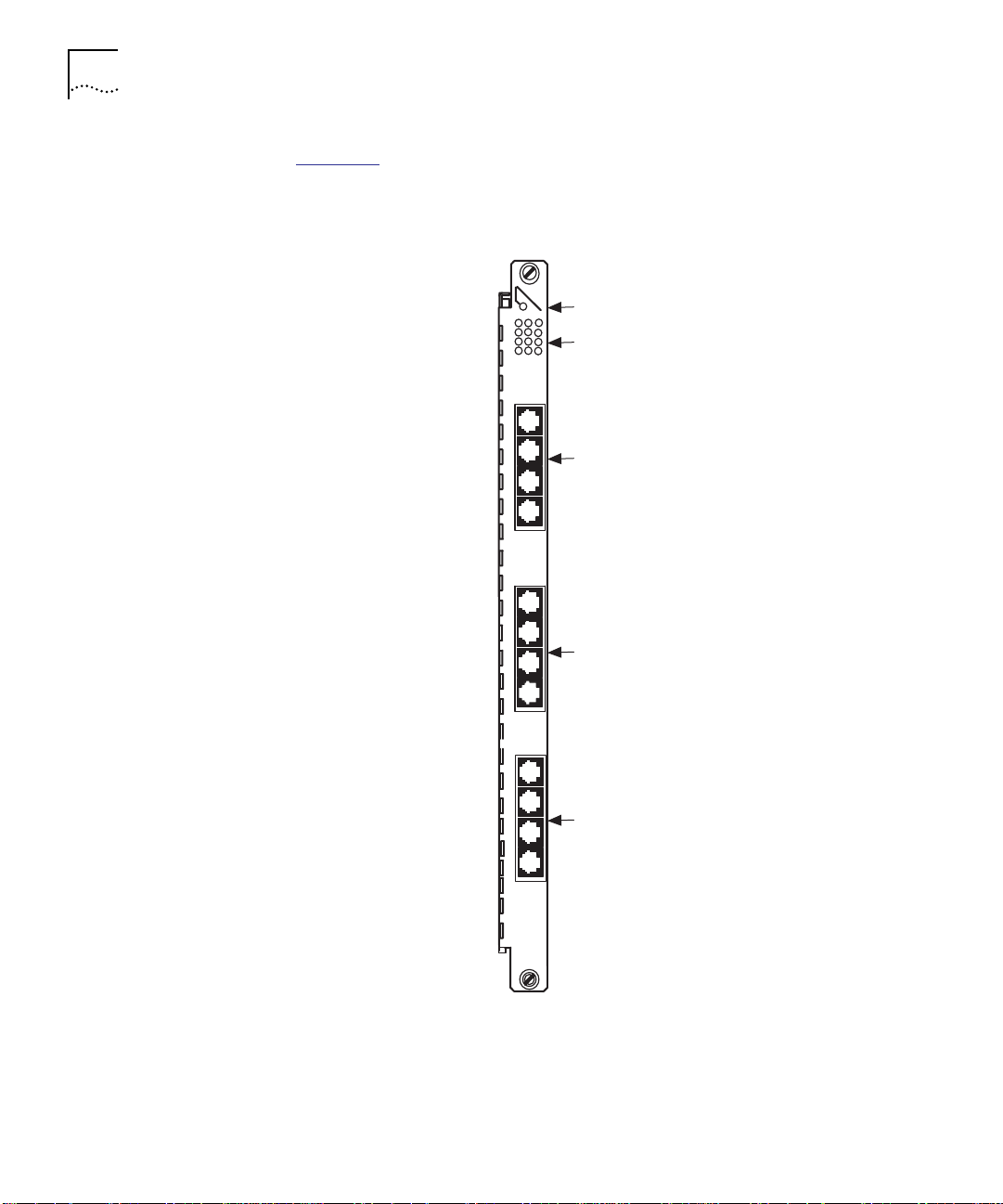
Figure 1-1
illustrates the front panel of the 12-Port 100BASE-TX
Workgroup FastModule.
MOD STAT
1
4
7
10
1X
2X
3X
4X
5X
6X
7X
8X
Module status LED
Port status LEDs
RJ45 connectors
(ports 1 to 4)
RJ45 connectors
(ports 5 to 8)
9X
10X
11X
12X
6512M-TX
RJ45 connectors
(ports 9 to 12)
Figure 1-1 CoreBuilder 5000 12-Port 100BASE-TX Workgroup FastModule
Front Panel
Page 19

100BASE-TX Workgroup FastModule Features 1-3
100BASE-TX Workgroup FastModule Features
Table 1-1 lists the CoreBuilder 5000 12-Port 100BASE-TX Workgroup
FastModule features.
Table 1-1 100BASE-TX Workgroup FastModule Features
Feature Description
Workgroup Fast
Ethernet
Connectivity to
Four Fast Ethernet
Channels
Fault Tolerance Ensures maximum network availability with no single
Remote Diagnostics Checks driver and receiver integrity using Remote
Repeater Statistics Provides IEEE Repeater statistics-gathering for monitoring
Inventory
Management
Power Management Supports CoreBuilder 5000 power management
Hot Swap Ability You can insert or remove 100BASE-TX Workgroup
In-band and
Out-of-band
Management
Provides high-density workgroup Ethernet FastModules
for implementation of Fast Ethernet to the desktop.
Workgroups help you achieve reduced traffic congestion
and increased service levels on the existing network by
implementing microsegmented Fast Ethernet.
Connects to each of the four Fast Ethernet channels
located on the TriChannel
CoreBuilder 5000 hub.
point of failure (redundant link).
Diagnostics mode. Setting a port to this mode allows the
port to indicate a receive link error to the
externally-connected port by not transmitting any link
signals.
of CoreBuilder 5000 network management architecture.
In addition, the 12-Port 10BASE-TX module supports
Repeater Management Information Base (MIB) statistics
through the terminal without the need for a Network
Monitor Card.
Maintains inventory information for the 12-Port
100BASE-TX module in non-volatile RAM (NVRAM).
Information includes the module serial number, power
requirements, power class settings (for example, power
on priority), date of manufacture, and a user note pad for
entering installation-specific information.
architecture which enables the hub to intelligently enable
or disable modules depending on the available power in
the system.
FastModules without powering off the CoreBuilder 5000
chassis.
Provides in-band SNMP and TELNET management through
the 3Com CoreBuilder 5000 Distributed Management
Module. Also provides out-of-band SLIP management.
®
backplane of the
Page 20
1-4 INTRODUCTION
To access in-band management in a hub with all 100BASE-TX
Workgroup FastModules, you must have another type of FastModule,
SwitchModule, or 10BASE-T Ethernet module and network monitor
card installed.
Managing
100BASE-TX
Workgroup
FastModules
Determining Model
Number
You can manage CoreBuilder 5000 100BASE-TX Workgroup
FastModules using the DMM command line interface.
The DMM supports:
■ In-band management using SNMP (Simple Network Management
Protocol) or TELNET
■ Out-of-band management using SLIP (Serial Line Interface Protocol)
for TELNET and SNMP
You must use DMM software Version v4.1 or later to manage and
configure the 12-Port 100BASE-TX Workgroup FastModules.
You need to determine your model number to:
■ Be able to perform configurations effectively
■ Identify your product for product orders or customer support
■ Make certain you have the correct model number
The model number on 100BASE-TX Workgroup FastModule faceplate
may differ slightly from the model number registered in the DMM or
Advanced DMM software. To determine your FastModule model
number for product orders or customer support:
1 Use the model number registered in the DMM or Advanced DMM
software (to determine your software version).
2 Add the prefix 3C9 to the model number.
For example, use the number 3C96512M-TX for Model
Number 6512M-TX.
To determine the 100BASE-TX Workgroup FastModule model number,
enter the command SHOW MODULE ALL at the DMM prompt and use
the model number listed in the Module field.
Page 21

100BASE-TX Workgroup FastModule Features 1-5
100BASE-TX
Workgroup
FastModules
Table 1-2
Table 1-2 100BASE-TX Workgroup FastModules
Model Number Occupies Ports
3C96512M-TX (faceplate shows
6512M-TX)
describes the 100BASE-TX Workgroup FastModule.
1 slot 12 100BASE-TX ports with
RJ-45 shielded connectors
Page 22

Page 23

2
DESIGNING YOUR NETWORK
Implementing
100BASE-TX
FastModules in the
Network
Software
Requirements
This chapter describes how to configure networks that use the
CoreBuilder
Workgroup FastModules.
This chapter contains the following sections:
■ Implementing 100BASE-TX FastModules in the Network
■ Using Module Workgroups
■ Setting Redundant Links
■ Making Network Connections
■ Sample 100BASE-TX Workgroup FastModule Configuration
This section describes the following topics:
■ Software Requirements
■ Network Configuration Rules
This chapter describes how to use the CoreBuilder 5000 hub with the
12-Port 100BASE-TX Workgroup FastModule.
You must have the 3Com
Module (DMM) and the advanced DMM/Controller module software
Version v4.1 or later to manage and configure 12-Port 100BASE-TX
Workgroup FastModules.
™
5000 hub and CoreBuilder 5000 12-Port 100BASE-TX
®
CoreBuilder 5000 Distributed Management
Page 24

2-2 DESIGNING YOUR NETWORK
Network
Configuration Rules
This section describes general rules for configuring a Fast Ethernet
network using twisted pair as the horizontal medium (connection to
printers, computers). It also provides rules to ensure that your network
configuration conforms to distance limitations imposed by Ethernet and
networking equipment.
The following topics are discussed:
■ Before Configuring Your Network
■ Basic Network Rules
■ Network Backplane Restrictions
Before Configuring Your Network
Before you configure your network, consider your:
■ Plans for expansion – If the network expands beyond a certain
size, you may need to add additional internetworking devices.
■ Maximum cable length – Cabling requirements include:
■ 100 Ohm 2-pair Category 5 UTP for up to 100 meters (328 feet)
■ 100 Ohm STP for up to 100 meters (328 feet)
■ Management access – For in-band management through the
DMM, SNMP and TELNET require another type of Downlink
Fastmodule, SwitchModule, or 10BASE-T Ethernet module and
network monitor card installed in the hub.
Out-of-band management requires Serial Line Interface
Protocol (SLIP) (includes SNMP, TELNET) and Direct Asynchronous
terminals.
Page 25

Implementing 100BASE-TX FastModules in the Network 2-3
Basic Network Rules
This section lists basic network rules for constructing your network
using Fast Ethernet:
For hardware-specific information on the 100BASE-TX Workgroup
FastModule, refer to Appendix A, Specifications
■ The 100BASE-TX Workgroup FastModules are a Class 1 repeater. A
.
Class 1 repeater has an internal delay that functions as follows:
■ Only one repeater can exist between any two DTE devices within
a single collision domain when you use two maximum cable
length segments.
■ An internal delay is the time delay between the system’s sensing
of the first data bit received and the sensing of the first data bit
transmitted on a 100 Mbps network.
Multiple 100BASE-TX Workgroup FastModules on the same network
(single backplane channel) makes 1 repeater.
■ The maximum UTP cable length between hub and connected
workstations is 100 meters (328 feet).
■ Use 2-pair Category 5 UTP or STP cable for backbone connections.
Backbone cabling is the main transmission medium used to
interconnect workgroups on a network.
■ Use with other switching FastModules except when other switching
FastModules are configured with VLANS (for detailed information on
switching fast modules, refer to the CoreBuilder 5000 FastModule
User Guide).
Network Backplane Restrictions
The CoreBuilder 5000 hub has capacity for four Fast Ethernet channels
(FastChannels). When you use assign a FastModule backplane port to
a CoreBuilder 5000 FastChannel, one or more backplane channels
become unavailable for use.
Page 26

2-4 DESIGNING YOUR NETWORK
Table 2-1 lists the backplane channels that become unavailable for each
Fast Ethernet Channel assignment.
Table 2-1 Fast Ethernet Channel Assignment Effect on Backplane Channels
Using Module Workgroups
Workgroup
Definition
Assigning a
Backplane Port to
FastChannel
1 2 7, 8, and 9 4 and 5
2 1 and 2 5, 6, 10, and 11 3 and 6
3 1 1, 2, 3, and 4 1 and 2
4 3 13, 14, 15 7 and 8
Disables
Ethernet
Channel
Disables Token
Ring Channel
Disables FDDI
Channel
When you set up a 12-Port 100BASE-TX FastModule as a
fully-configured workgroup module, the resultant logical network
configuration supports one workgroup per module. Because a
managed CoreBuilder 5000 hub may contain as many as seventeen
12-Port 100BASE-TX FastModules, it is possible to configure your hub
with a maximum of 17 workgroups or a maximum of 204 ports in a
single workgroup.
Workgroups are individual groups on modules set up to divide your
network layout into smaller isolated networks. The CoreBuilder 5000
100BASE-TX Workgroup FastModule is a Fast Ethernet module that
enables administrators to connect up to 12 network devices. You can
attach workstations to the 12-Port 100BASE-TX Workgroup FastModule
using RJ-45 connectors directly to the front of the module.
Workgroups:
■ Provide network administrators with high flexibility in organizing
their network.
■ Decrease the amount of traffic on the backplane segments of the
hubs in which the workgroups reside.
■ By creating module workgroup networks instead of separate
backplane segment networks, you can configure a maximum of
17 workgroups per hub using no backplane bandwidth.
Page 27

Setting Redundant Links 2-5
Setting Redundant Links
Setting Redundancy
Between Two Ports
on One FastModule
Setting Redundancy
Between Ports on
Two FastModules
When you set up a redundant link between ports on CoreBuilder 5000
hubs, the resultant configuration prevents a network failure. This
section describes how to set up redundancy between:
■ Two ports on one 100BASE-TX Workgroup FastModule
■ Two ports on two separate 100BASE-TX Workgroup FastModule
To connect two links to two ports on one 12-Port 100BASE-TX
FastModule:
1 Issue the SET PORT MODE REDUNDANT network management
command.
2 Specify the primary link port and the backup link port.
For example, if you set up a redundant link using the following
command:
SET POR T 8.5 MODE REDUNDANT 8.7
Port 5 in slot 8 becomes the primary link and port 7 in slot 8
becomes the backup link.
To connect two links to two ports between two 12-Port 100BASE-TX
FastModules:
1 Issue the SET PORT MODE REDUNDANT network management
command.
2 Specify the primary link port and the backup link port.
For example, if you set up a redundant link using the following
command:
SET PORT 12.4 MODE REDUNDANT 8.9
Port 4 in slot 12 becomes the primary link and port 9 in slot 8
becomes the backup link.
CAUTION: You can set redundancy between a port on the 100BASE-TX
Workgroup FastModule and a port on any 10 MB module. However,
you should set the 100 MB port as the primary port and the redundant
or buddy port as the backup port.
Page 28

2-6 DESIGNING YOUR NETWORK
After you configure redundancy:
1 A switchover to the backup link occurs under three conditions:
■ Link failure
■ Port partition
■ Link unstable (carrier integrity failure, port isolated)
2 The switchover occurs and the backup link becomes operational. The
system performs a switchover back to the primary link automatically
after the failure or port partition problem is resolved.
Although you can configure redundancy between two ports on a single
module, you should configure redundancy between two ports on two
different modules. This provides additional protection if, for example,
one of the modules becomes inoperative.
If redundant front panel ports are set up from a Workgroup
FastModule to a single switching FastModule, then configure the
single switching FastModule using resilient link (
of a main link and a standby link
FastModule to Remote Diagnostic mode. This sets up the remote fault
tolerance feature.
a resilient link consists
) and set the port on the Workgroup
Refer to the CoreBuilder 5000 Distributed Management Module User
Guide for more information on setting redundancy between ports and
refer to the CoreBuilder 5000 FastModule User Guide for detailed
information on switching FastModules.
Page 29

Making Network Connections 2-7
Making Network Connections
Table 2-2 summarizes the possible schemes for connecting
100BASE-TX Workgroup FastModules in your network.
Table 2-2 Network Connections
To connect a
hub to a
Node RJ-45 port Straight-through
Hub 100BASE-TX
Use this type of
connector
100BASE-TX Straight-through
Switch
FastModule using
RJ-45 connectors
...And this type
of cabling Purpose
UTP
UTP
Category 5
crossover UTP cable
Connects PCs,
servers, and
other network
devices directly
connected to the
hub.
Connects
another hub.
When you make
this connection,
you must
connect to the
front panel TX
port on a 7-port
100BASE-FX/TX
FastModule.
Sample
100BASE-TX
Workgroup
FastModule
Configuration
The maximum allowable distance between the hub and a PC, server,
or other devices is 100 meters of Category 5 UTP cable. The UTP cable
used for hub-to-node connections is a straight-through connection. No
crossovers should be present.
Figure 2-1 shows a sample network configuration that implements
100BASE-TX Workgroup FastModules and CoreBuilder 5000 Switching
FastModules in the CoreBuilder 5000 hub.
A typical configuration for the 100BASE-TX Workgroup FastModule is
when you have a CoreBuilder 5000 7-slot hub running several 12-port
100BASE-TX Workgroup FastModules with a 100BASE-TX/FX
FastModule for a Fast Ethernet downlink connection over the
backplane.
Page 30

2-8 DESIGNING YOUR NETWORK
The 7-port 100BASE-FX/TX FastModule provides seven switched Fast
Ethernet connections to any one of four CoreBuilder 5000 FastChannel
backplane networks. When used in conjunction with other
CoreBuilder 5000 FastModules, this FastModule lets you create
backbone and floor configurations based on shared and switched Fast
Ethernet and Ethernet. The 100BASE-TX ports on the 7-port
FastModule using RJ-45 connectors can be used to provide dedicated
100 Mbps connections to workgroup servers
Users are connected to each of the 12 ports on the 100BASE-TX
Workgroup FastModule distributed among the four Fast Ethernet
channels. These channels are aggregated and downlinked through the
switching 100BASE-TX/FX FastModule in the CoreBuilder 5000 hub.
For more information on switching fast modules, refer to the
CoreBuilder 5000 FastModule User Guide.
Server
CoreBuilder 5000 Integrated System Hub
100 Mbps
(connection over
the backplane)
7-port 100BASE-FX/TX
Switched FastModule
100 Mbps
Figure 2-1 Sample 100BASE-TX Workgroup FastModule Configuration
Server
100 Mbps
12-port
100BASE-TX
Workgroup
FastModules
Server
Page 31

3
INSTALLING THE MODULE
This chapter describes how to install the CoreBuilder™ 5000
12-Port 100BASE-TX Workgroup FastModule.
A quick start and reference guide for the 3Com® 12-Port 100BASE-TX
Workgroup FastModule lists LED indicators, installation information, and
other module information.
This chapter contains the following sections:
■ Precautionary Procedures
■ Unpacking Procedures
■ Quick Installation
■ Setting DIP Switches
■ Installing the Module
Precautionary Procedures
Read the precautionary procedures before unpacking the module.
CAUTION: Electrostatic discharge (ESD) can damage static-sensitive
devices on circuit boards.
Follow these precautions when you handle the 12-Port 100BASE-TX
Workgroup FastModule:
■ Do not remove the board from its antistatic shielding bag until you
are ready to inspect or install it.
■ Handle the board by the faceplate only.
Page 32

3-2 INSTALLING THE MODULE
Use one of the following proper grounding techniques when you install
the 12-Port 100BASE-TX Workgroup FastModule:
■ Use a foot strap and grounded mat or wear a grounded static
discharge wrist strap.
■ Touch the grounded rack or other source of ground just before you
handle the module and I/O cards.
CAUTION: Although the LEDs used in this product meet the
regulatory requirements for casual exposure to the eye, as with any
source of bright light, it is advised that one does not look into the light
source.
Unpacking Procedures
To unpack the 12-Port 100BASE-TX Workgroup FastModule:
1 Verify that the 12-Port 100BASE-TX Workgroup FastModule (Model
Number 6512M-TX) is the model you ordered by checking the model
number listed on the side of the shipping carton.
2 Note that the product model number printed on the shipping box
differs from the model number on the product. The model number on
the shipping box contains the prefix ’3C9’.
3 Remove the 12-Port 100BASE-TX Workgroup FastModule, in its
antistatic bag, from the shipping carton.
4 Remove the module from the antistatic shielding bag and inspect it for
damage.
Always handle the 12-Port 100BASE-TX Workgroup FastModule by the
faceplate, being careful not to touch the components. If the module
appears to be damaged, return it to the antistatic shielding bag, repack
it in the shipping carton, and contact your local supplier.
Keep the shipping carton and antistatic shielding bag in which your
module was shipped for future storage or shipment.
5 Record the serial number of your 12-Port 100BASE-TX Workgroup
FastModule. The Hub Planning Chart, located in the CoreBuilder 5000
reference binder, and the Module Planning Chart supplied with your
module are provided for this purpose.
Page 33

Quick Installation 3-3
Quick Installation Table 3-1 outlines the steps for the installation of your module. If you
are familiar with installing CoreBuilder 5000 modules, use this table as
a checklist. Otherwise, consult the remainder of this chapter.
Table 3-1 Quick Installation Checklist
Step Procedure Chapter/Section
1 Verify that your network complies with the
basic rules for network design.
2 Unpack the module. Chapter 3, Unpacking
3 Configure the DIP switch settings. If you
have a network management module
installed in the hub, configure the module
using the management commands described
later in this chapter.
4 Enter the SHOW POWER1 command at the
5 Insert a 12-Port 100BASE-TX Workgroup
6 Establish connections from the 12-port
7 Verify LED status for normal operation. Chapter 4, Verifying
1
Refer to the CoreBuilder 5000 Integrated System Hub Installation and Operation Guide for
details on hub power requirements.
command line of the terminal. This
command displays current power
requirements for the hub.
Fastmodule into one open slot in the hub.
Fasten the ejectors and tighten the faceplate
screws.
100BASE-TX Workgroup Fastmodule to
devices using the appropriate connectors and
cabling.
Chapter 2, Designing
Your Network
Procedures
Chapter 3, Setting DIP
Switches
Chapter 3, Installing
the Module
Chapter 3, Installing
the Module
Chapter 3, Installing
the Module
LED and Network
Operation
For information about potential problems, consult the troubleshooting
techniques in Chapter 5
.
Page 34

3-4 INSTALLING THE MODULE
Setting DIP Switches
If you are using a management module and do not plan to use the DIP
configuration command, skip this section and go to the section
Installing the Module
The CoreBuilder 5000 Ethernet 12-Port 100BASE-TX Workgroup
FastModule has an 8-position DIP switch. All of the DIP switch settings
on the 12-Port 100BASE-TX Workgroup FastModule are ignored if an
appropriate CoreBuilder 5000 network management module (for
example, DMM Version v4.10 or later) is already installed in the hub.
Use network management commands, rather than the DIP switches, to
configure the module.
This section describes:
■ DIP Switch Features
■ Setting the DIP Switches
■ DIP Switch Definition
DIP Switch Features Use the DIP switch to:
■ Select a network for all ports on the 12-port 100BASE-TX
Workgroup FastModule
■ Choose the primary module configuration:
in this chapter.
Setting the DIP
Switches
■ Non-volatile RAM configuration (software configuration)
■ DIP segment selection (DIP-specified module configuration)
To set the module to access the DIP switch settings when using a
management module, issue the
SET DEVICE DIP_CONFIGURATION
command from the management module.
If you do not have a CoreBuilder 5000 Distributed Management
Module installed in your hub, your hub configuration defaults to the
DIP switch settings on the module.
Page 35

Setting DIP Switches 3-5
Figure 3-1 shows the DIP switch location on the module.
1
23
4
56
DIP switch
78
TX ports
(RJ-45)
NOT USED
NOT USED
NOT USED
NV
ISOLATE
NOT USED
CH SEL 1
CH SEL 0
12345678
96-pin
backplane
connector
Figure 3-1 12-Port 100BASE-TX Workgroup FastModule DIP Switch Location
DIP Switch Definition The DIP switch settings on the module refer to the backplane
connection as the channel selection (CH SEL). The channel setting and
the network setting are the same.
Use the DIP switch settings on the 12-Port 100BASE-TX Workgroup
FastModule to assign the module to network one through four or to
the isolated segment.
Table 3-2
■ Switches 1 and 2 – Enable you to configure all ports to one of the
describes the following DIP switch settings:
Fast Ethernet backplane segments (Fast Ethernet 1 to Fast
Ethernet 4).
■ Switch 3 – No operation.
■ Switch 4 – Enables you to configure all ports to one Isolate
segment.
Page 36

3-6 INSTALLING THE MODULE
■ Switch 5 – Enables you to switch between non-volatile RAM
(NVRAM) or DIP-switch controlled configuration.
■ Switches 6, 7, and 8 – Not used.
Table 3-2 Network Selection DIP Switch Settings
Switch
Network Selection
1 (default) Off Off Off
2 Off Off On
3 Off On Off
4 Off On On
Isolated On N/A N/A
1
By default, Switch 5 is set to NVRAM. When enabled, settings stored in
NVRAM take precedence over DIP Switch settings 1 through 3.
Settings
Switch 4 Switch 2 Switch 1
The DIP switch legend (Figure 3-1
1
) on the module refers to the
backplane connection as the channel selection (CH SEL). The channel
setting and the network setting are the same. Ports set to the same
network communicate with each other. If the switch labeled ISOLATE is
On, it sets the module to Isolated.
Default DIP Switch Settings
When the 12-Port 100BASE-TX Workgroup FastModule is first
installed, the hub checks for DIP witch configuration settings in the
DMM and decides the following:
■ If the hub is managed, the module uses the DIP switch settings from
the DMM.
■ If the hub is unmanaged, then the 12-Port 100BASE-TX Workgroup
FastModule:
a Checks for configuration settings stored in NVRAM.
b Checks the DIP switches for configuration information if there are
no configuration settings in NVRAM or DIP Switch is set to
DIP-switch controlled configuration.
Page 37

Installing the Module 3-7
Installing the Module
You do not need to power off the CoreBuilder 5000 hub to install or
remove the 12-Port 100BASE-TX Workgroup FastModule. You can
insert the module while the hub is operating (this is called a hot swap).
To install a 12-Port 100BASE-TX Workgroup FastModule into the hub:
1 Use one of the following proper grounding techniques when you install
the 12-Port 100BASE-TX Workgroup FastModule:
a Properly ground yourself prior to handling the 12-Port 100BASE-TX
Workgroup FastModule.
b Attach a static wrist guard to yourself or touch a grounded static
mat prior to handling the 12-Port 100BASE-TX Workgroup
FastModule.
2 Configure the 12-Port 100BASE-TX Workgroup FastModule:
a If you plan to install the 12-Port 100BASE-TX Workgroup
FastModule in a managed hub (for example, DMM Version v4.10),
go to step 3 to complete the installation. To configure the
appropriate settings, refer to the section Configuring the Module
later in Chapter 4.
b If you plan to insert the 12-Port 100BASE-TX Workgroup
FastModule in an unmanaged hub, configure the DIP switch settings
on the module to the desired settings (refer to the section Setting
DIP Switches earlier in this chapter) and go to step 4.
3 To determine if the hub has enough power for the new module, from
the DMM command line, enter the SHOW POWER BUDGET command.
Refer to Appendix A, Specifications
for each of the specified watts ranges.
Refer to the CoreBuilder 5000 Distributed Management Module
Commands Guide for information on the SHOW POWER BUDGET
command.
4 Locate an open slot in the hub. Remove the appropriate number of
blank panels on the hub to expose a slot for the module, if necessary.
, for details on power requirements
Page 38

3-8 INSTALLING THE MODULE
Figure 3-2 shows the installation of a CoreBuilder 5000 module (The
module in the diagram is only a representation of a CoreBuilder 5000
module, not the 100BASE-TX module).
Figure 3-2 Installing a CoreBuilder 5000 Module
5 Insert the module into the board guides at the top and bottom of the
slot and slide it into the hub by pressing firmly at the top and bottom
of the faceplate.
Page 39

Installing the Module 3-9
6 Close the 12-Port 100BASE-TX Workgroup FastModule ejectors
(Figure 3-3
).
Opened
ejector
Figure 3-3 Opened and Closed Module Ejectors
Closed
ejector
7 Using your fingers, fasten the spring-loaded screws on the front of the
12-Port 100BASE-TX Workgroup FastModule faceplate to the hub (do
not overtighten).
8 Attach the RJ-45 cable connectors to the RJ-45 connectors on the front
of the module.
Page 40

Page 41

4
CONFIGURING THE MODULE
Configuring the Module
This chapter describes how to configure the 3Com
CoreBuilder
A quick start and reference guide for the 12-Port 100BASE-TX
Workgroup FastModule lists the LED indicators and other module
information.
This chapter contains the following sections:
■ Configuring the Module
■ Showing Module Configurations
■ Gathering Repeater Statistics
■ Monitoring the Front Panel
■ Verifying LED and Network Operation
This section describes how to configure the module using network
management commands. The following network management
commands are used to configure the 12-Port 100BASE-TX Workgroup
FastModule:
■ Set port mode commands
™
5000 12-Port 100BASE-TX Workgroup FastModule.
■ Set port alert filter command
■ Select the Fast Ethernet network on the module
For additional information on network management commands, refer
to the CoreBuilder 5000 Distributed Management Module Commands
Guide.
Page 42

4-2 CONFIGURING THE MODULE
Configuration
Overview
The CoreBuilder 5000 Distributed Management Module (DMM) and the
Advanced DMM/Controller Module provide network management for
the CoreBuilder 5000 hub and its modules. Use network management
commands, rather than the DIP switches, to configure the module. All
of the DIP switch settings on the 12-Port 100BASE-TX Workgroup
FastModule are ignored if an appropriate CoreBuilder 5000 Distributed
Management Module (DMM Version v4.10 or later) is already installed
in the hub.
If network management is present when you first install the module,
the:
■ Network defaults to isolated mode.
■ Ports are automatically disabled (so that users cannot join the
network undetected by network management).
Therefore, you must enable the ports you want to use and set the
module ports to the appropriate network using management
commands.
Do not manage (get statistics or configure) this module from a slave
management module.
Set Port Mode
Commands
To enable ports and set the module ports to the appropriate network,
use the following SET PORT MODE commands:
■ Enable/Disable/Shutdown Ports Command
■ Setting Port Redundancy Command
■ Setting Remote Diagnostics Command
■ Set Port Alert Filter Command
■ Network Selection
Page 43

Configuring the Module 4-3
Enable/Disable/Shutdown Ports Command
This command allows you to enable, disable, and shutdown each port
on the 12-Port 100BASE-TX Workgroup FastModule.
When a port is set to:
■ Enable – It transmits to and receives data from the network to
which the port is assigned.
■ Disable – It does not transmit or receive data. (Link integrity is
unaffected).
■ Shutdown – It is disabled, turns off link integrity, and does not
transmit or receive data. The port responds with status OFF at the
terminal.
Use the following command to enable, disable, or shutdown a port:
SET PORT {
slot.port
{
slot
} MODE {disable}
.all} {enable}
{shu tdow n}
Setting Port Redundancy Command
This command allows you to set redundancy between ports. When
you set two ports redundant to each other, the secondary port takes
over if the primary port fails.
To support 100BASE-TX Fast Ethernet features, you may use either
another 100 MB port or another 10BASE-T port as the backup.
Use the following command to set redundancy between ports:
SET PORT {
slot .por t
{
slot .por t
} MODE {redundant}
} {non- re dund an t}
For an example of port redundancy, refer to the section Setting
Redundant Links in Chapter 2.
Setting Remote Diagnostics Command
This command allows the 12-Port 100BASE-TX Workgroup FastModule
to detect certain unusual failure conditions. This mode completes the
fault-tolerance of a redundant link.
Page 44

4-4 CONFIGURING THE MODULE
Use the following command to set remote diagnostics:
SET PORT {slot.
{slo t.po rt } {NON _R EMOT E_ DI AGNOS TI CS}
port
} MODE {REMOTE_DIAGNOSTICS}
In the command above, the last variable, slot.port, is optional. If
entered, both ports are placed into remote diagnostic mode and
referred to as buddy ports to each other. If you turn one port off (place
in non-remote diagnostic mode) then the other port is also turned off.
Set Port Alert Filter Command
This command allows you to override the Port Alert Filter feature on a
port-by-port basis. The Port Alert Filter feature enables or disables the
DMM delivery of port up and port down traps. You can use this
command to continue to monitor port status on crucial ports (file
servers, for example), while alerts from other ports are disabled.
Configure Alert Filter to:
■ Enable – To use the Port Alert filtering feature.
■ Disable – To allow all port up and port down alerts to display.
Use the following command to enable or disable the port up and port
down alerts for a port:
SET PORT{
slot .por t
{
slot.
all} {enabl e}
} ALE RT_ FILT ER { disa bl e}
The following output is an example of the SET PORT ALERT_FILTER
command issued for port 1 of a 12-port module in slot 1:
CB50 00> set po rt 1.1 aler t_filter di sable
Port 01 .01 Alert Filter set to DISABLE
Perform the SET ALERT PORT_UP_DOWN FILTER command on the DMM
before you use the SET PORT ALERT_FILTER command on the module.
For more information on this command, refer to the CoreBuilder 5000
Distributed Management Module Commands Guide.
Page 45

Configuring the Module 4-5
Network Selection
This command provides module-level configuration flexibility using the
unique architecture of the CoreBuilder 5000 hub. You can assign the
module to:
■ Any of four Fast Ethernet backplane segments
■ An Isolated segment
Use the DIP switch settings on the 12-Port 100BASE-TX Workgroup
FastModule to assign the module to network one through four or to
the isolated segment. Network management, also lets you assign the
module to a network.
Use the following command to assign the module to a network:
SET MO DUL E {
slot
.1} NETWORK {fast_ether_1..._4}
{isolated}
This command also assigns users to a backplane segment or the
isolated segment.
The 100BASE-TX Workgroup FastModule cannot be connected to a Fast
Ethernet channel that has a Virtual LAN trunk (VLT) configured from a
switching FastModule. An error condition occurs. The following error
message displays:
Virtua l LAN Trunk Module has been E nabled fo r this
Networ k by other module(s) co nfigured to this Ne twork;
comman d aborted
For example, do not configure a switched FastModule with VLT mode
disabled to a network (Fast Ethernet 1) which is already configured
with VLT mode enabled.
Page 46

4-6 CONFIGURING THE MODULE
Showing Module Configurations
Show Module
Command
You can display status information about the 12-Port 100BASE-TX
Workgroup FastModule using the following network management
commands:
■ SHOW MODULE
■ SHOW PORT
This command enables users to display both brief and verbose
information about a particular module.
Use the following command to display module information:
SHOW MODULE {
slot.
1} {verbose}
{no_ve rb ose }
The following output is an example of the SHOW MODULE VERBOSE
command issued for a 12-Port 100BASE-TX Workgroup FastModule
installed in slot 10:
CB50 00> show m odule 10.1 verbose
Slot Module Version N etwork Gen eral Info rmation
------ --------- -------- --------------- ------
10.01 6512M -TX‘v1.00 FAST_ETH ER_1 Port( s) are down
6512M- TX: FastMo dule 100B ASE-TX 12Por t Shared F ast Etherne t
Boot Ve rsion: v1.00
Networ k DIP Setti ng: FAST_E THER_1
Non-Volatile DIP Setting: DISABLED
Show Port Command This command enables users to display brief and verbose information
on both individual ports and all ports collectively.
Use the following command to display port information:
SHOW PORT {
slot.port
{
slot.
all} { no _verb os e}
} {ve rbo se}
Page 47

Gathering Repeater Statistics 4-7
The following output is an example of the SHOW PORT VERBOSE
command issued for port 2 on a 12-Port 100BASE-TX Workgroup
FastModule installed in slot 10:
CB50 00> sho w port 10.2 verbose
Port Di splay for Module 6512M -TX:
Port Mo de Status Network General Informat ion
----- ----- --- ------ ---- ---- --------- --- ------- ------
10.02 E NABLED OKAY FAST_E THER_1
Alert Filter: DISABLED
Port Co nnector: RJ-45
Gathering Repeater Statistics
Statistics-Gathering
Process
This section describes how the 12-Port 100BASE-TX Workgroup
FastModule:
■ Gathers repeater statistics
■ Monitors network statistics
The 12-Port 100BASE-TX Workgroup FastModule gathers repeater
statistics for each port (for example, collision, partition, late events,
data rate mismatch, and short event statistics). This module gathers
repeater statistics without the use of a network monitor card.
Repeater statistics are gathered from traffic only entering through the
front panel ports on the 100BASE-TX Workgroup FastModule. The only
statistics counted are those received on the front panel ports.
The repeater statistics that are available include:
■ Network – Network statistics are presented by gathering events
from all ports on the 12-Port 100BASE-TX Workgroup FastModules
specified on the network. Network statistics are the total amount of
all of the module statistics together.
■ Module – Module statistics represent the total events from traffic
entering on all ports on a specified module.
■ Port – Per-port statistics are a count of events from traffic entering
the specified port.
Page 48

4-8 CONFIGURING THE MODULE
Monitor Command
This Monitor command:
■ Allows you to monitor each network (individually) by specifying the
backplane or isolated segment to which the module is configured.
■ Supports repeater statistics at the module (group) and port levels.
You cannot enter DMM commands while in Monitor mode.
Use the following command to monitor repeater statistics:
MONITO R {mm:ss} {RE PEATER} { fast_eth erne t_1..._4, isolated}
{module} {
{port} {
slot
slot
}
.port}
The system-specified range of time for the polling interval is 00 to
30 minutes (mm) and 05 to 59 seconds (ss). Use these ranges when
specifying a length of time between monitor display updates.
You must set a polling interval for the Monitor command. The polling
interval defines the time between monitor display updates. The monitor
displays the statistics for the last polling interval and a cumulative count
(initialized to all zeros at the start of the monitor display). The Monitor
command normalizes the repeater statistics from the values when
invoked and when ever a counter rolls over or reaches maximum count.
The following output is an example of the MONITOR REPEATER
command for a 12-Port 100BASE-TX Workgroup FastModule assigned
to network Fast_Ethernet_1.
Page 49

Gathering Repeater Statistics 4-9
This example monitors Fast_Ethernet_1 every 10 seconds:
CB50 00> m onitor 00:10 repeater fast_eth er_1
Repeater Statistics for FAST_ETHER_1
---------------------------------------------------------
------ --------- ----------------------- --------- ----------Transmit Collisions 0 0
Readable Frames 51857 28255
Readable Octets 53308996 29046140
Upper 3 2 Readable Octets 142 1
Runts 0 0
FCS Err ors 0 0
Late Events 0 0
Short Event s 0 0
Frame Too Lo ng 0 0
Very Long Ev ents 0 0
Alignm ent Errors 0 0
Collisions 0 0
Data Ra te Mismatc hes 0 0
Auto Pa rtition Co unt 0 0
Isolates 0 0
Symbol Erro rs 0 0
Last Source Address N/A 08-01 -20-21-3d -52
Display wil l refresh e very 10 seconds.
Press C TRL-C to exit.
Cumula tive Last T ime Interval
In the previous example, the Upper 32 Readable Octets display 140.
(The actual count of octets is 142 x (times) 2
32
.)
100BASE-TX Workgroup FastModule Version v1.10 and DMM Version
v5.0 support three new 100MB repeater statistics (Upper 32 Readable
Octets, number of Isolates, and Symbol Errors) using the SHOW
COUNTER command and the MONITOR command. 100BASE-TX
Workgroup FastModule Version v1.10 works with DMM Version v4.10.
However, DMM Version v5.0 is required to display the three new
repeater statistic entries.
If you are using DMM Version v5.0, you must use 100BASE-TX
Workgroup FastModule Version v1.10 to properly display any statistics.
Transmit collisions only display on a network level (not port or module
level). Transmit collisions statistics are not supported by this module.
Status on the module has a periodic rate of gathering statistics and
updating approximately every second.
Page 50

4-10 CONFIGURING THE MODULE
Table 4-1 describes repeater statics.
Table 4-1 Repeater Statistics Description
Field Description
Readable Frames Readable (uncorrupted) frames received at repeater.
Readable Octets Readable (uncorrupted) octets received at repeater (the
lower 32 bits of a 64-bit readable octets counter.
Upper 32 Readable
Octets
Runts Packets less than 64 bytes.
FCS Errors Frame Check Sequence errors.
Late Events Collision detected after 512 bits were received from a
Short Events Packets less than 80 bit times received.
Frame Too Longs Frames in excess of 1518 bytes received.
Very Long Events Port entered a jabber lockup state due to a timeout.
Alignment Errors Number of CRC errors that do not end on a byte
Collisions Total number of collisions detected.
Data Rate Mismatches Number of FIFO overflow and underflow occurrences.
Autopartition Count Number of times autopartition threshold has been
Isolates The number of automatic repeater port isolates as a
Symbol Errors Number of packets containing symbol errors.
Last Source Address
(port)
The upper readable (uncorrupted) octets (2**32)
received at repeater. It contains the upper 32 bits of a
64-bit readable octets counter.
port.
boundary.
passed.
consequence of false carrier events.
The source address of the last packet received by this
port.
Page 51

Gathering Repeater Statistics 4-11
Gathering Repeater Statistics Through SNMP
In addition to using DMM commands to gather information about
network traffic, you can submit SNMP (Simple Network Management
Protocol) requests for MIB objects that provide specific network
management information (displays repeater port statistics defined in the
MIB RFC 2108).
You can also submit SNMP requests through 3Com network
management applications such as Transcend LANsentry. (Transcend
uses SNMP to retrieve statistics, monitor the networks, and manage
modules and hubs.)
An SNMP agent resides on the Advanced/DMM Controller Module, so
anyone that has access to a community (set up on the Advanced/DMM
agent) can use SNMP commands to read and set MIB variables
(Transcend is not required).
The following is an example of a SNMP GET command of the
ReadableOctets and Upper32Octets counters from port 1 of a 100 MB
Repeater (100BASE-TX Workgroup FastModule) module occupying
slot 4 and set to fast_ethernet_1. This example uses the public
community. To use SNMP, you must have access to the community and
use the community name extension to indicate the network from which
to gather statistics from.
The community table is managed on the Advanced/DMM Controller
Module.
CB50 00> getone 151.104. 2.41 publ ic@fast_e thernet_ 1
rptrMo nitorPort Readable Octets.4.1
Repeater Statistics for FAST_ETHER_1
----------------------------------------------------------Name: rptrMonitorPortReadableOctets.4.1
Value: 374233968
CB5000> get one 151.104.2.41 publ ic@fast_e thernet_ 1
rptrMo nitorPort Upper32O ctets.4.1
Repeater Statistics for FAST_ETHER_1
----------------------------------------------------------Name: rptrMonitorPortUpper32Octets.4.1
Value: 3
Page 52

4-12 CONFIGURING THE MODULE
SHOW COUNTER REPEATER {fast_ethernet_1..._4, isolated} {mod ule} {slot}
Show Counter Command
This command provides you with detailed information on repeater
statistics at the time you enter the command.
Use the following command to view repeater statistics:
SHOW COUNTE R REPE ATER {fast_ et her net_ 1. .._4 }
{iso late d}
Use the following command to view statistics on an isolated network:
SHOW COUNTE R R EPEA TE R {is ol ated } {mod ule}
Use the following command to show network, module, and port-level
repeater statistics:
{port} {slot. port}
Both the MONITOR and SHOW COUNTER commands provide
information for ongoing network statistics. The MONITOR command
displays network statistics periodically at the time interval you specify in
the command. The SHOW COUNTER command displays repeater
statistics, at one time, since the last CLEAR COUNTER command.
Page 53

Gathering Repeater Statistics 4-13
The following output is an example of the SHOW COUNTER command
listing REPEATER statistics:
CB50 00> show counter repeater fast_ethernet_1 module 3
Repeat er Statist ics for Modu le 3 on FAS T_ETHER_1
------ --------- -------- ----------- --------- -------- -------Readable Frames 0
Readab le Octets 68900 0
Upper 32 Rea dable Octe ts 142
Runts 0
FCS Err ors 0
Late Events 0
Short Event s 0
Frames too L ong 0
Very Long Ev ents 0
Alignm ent Errors 0
Collis ions 0
Data Ra te Mismatc hes 0
Auto Pa rtition Co unt 0
Isolates 0
Symbol Erro rs 0
Transmit Collisions (display at the module level only)
Choose the CLEAR COUNTERS command to reset all the statistic
counters to zero. If the maximum limit of a counter is reached, the
counter rolls over. Each error type is followed by the number of packets
received containing that error.
Clear counter starts at the time you issued the Clear Counter
command.
For more information on repeater statistics, refer to the
CoreBuilder 5000 Distributed Management Module User Guide.
Page 54

4-14 CONFIGURING THE MODULE
Monitoring the Front Panel
Use the LEDs on the front panel of the 12-Port 100BASE-TX Workgroup
FastModule to monitor the status of each port. The 12-Port
100BASE-TX Workgroup FastModule has one Module Status LED and
12 bicolor port activity and status LEDs.
Module Status LED A single LED located at the top of the faceplate indicates the status of
the module (see Figure 4-1).
Port Status and
Activity LEDs
The 12-Port 100BASE-TX Workgroup FastModule has one bicolor LED
for each port. This LED is capable of displaying the following two
colors:
■ Green – Displays port status information
■ Yellow – Displays port traffic information
Page 55

Monitoring the Front Panel 4-15
Figure 4-1 shows the location of the LEDs. Each LED indicates the state
of a port as described in Table 4-2
MOD STAT
.
1
4
7
10
1X
2X
3X
4X
5X
6X
7X
8X
9X
10X
11X
12X
Module status LED
Port status LEDs
RJ45 connectors
(ports 1 to 4)
RJ45 connectors
(ports 5 to 8)
RJ45 connectors
(ports 9 to 12)
6512M-TX
Figure 4-1 12-Port 100BASE-TX Workgroup FastModule Faceplate
Page 56

4-16 CONFIGURING THE MODULE
Table 4-2 describes the states of port LEDs.
Table 4-2 12-Port 100BASE-TX Workgroup FastModule LED Interpretations
LED Name Color State Indicates
Module Status Green Off No power to hub or insufficient
power in the hub to support this
module.
Module download in progress.
Blinking Module failed self-diagnostics.
On Module is OK.
Port
Activity/Status
(Ports 1 to 12)
Green On Port enabled and link OK with no
traffic.
DMM initiated channel check.
1 blink Link failure on the port.
2 blinks Port partitioned because of excessive
collisions.
If a port partitions, it is automatically
reconnected to the network when
the problem no longer exists.
3 blinks Port jabber because long packets are
being sent over the network.
4 blinks Link unstable due to carrier
integrity failure.
Off Port or ports disabled or shutdown.
Yellow Off No packets are received on the
ports.
On Link OK. Heavy traffic activity on the
port.
Download to processor flash
memory.
Blinking Link OK. Normal activity on the port.
There is no DMM LED to report 100BASE-TX Workgroup FastModule
activity.
Page 57

Verifying LED and Network Operation 4-17
Verifying LED and Network Operation
Using the
CoreBuilder 5000
Controller Module
to Verify Bi-color
LED Operation
To determine if your configuration is operating correctly, you must verify
network operations. This section describes LED and Network verification
for the 12-Port 100BASE-TX Workgroup FastModule, including:
■ Using the CoreBuilder 5000 Controller Module to Verify Bicolor LED
Operation
■ Using the DMM to Verify Network Connections
For more information on the DMM, refer to the CoreBuilder 5000
Distributed Management Module User Guide.
The CoreBuilder 5000 hub controller module is equipped with a LED
Test button on the front panel. Use this button to verify LED operation.
When you press the LED test button:
1 The module initiates a test to all modules in the hub. All LEDs respond
by lighting continuously for approximately 5 seconds.
2 During this time period, the LEDs should alternate between green and
yellow about every ½ second. Any LED that does not light is defective.
The LED test does not disrupt network operation.
Using the DMM to
Verify Network
Connections
During a software download to the 12-Port 100BASE-TX Workgroup
FastModule, the Module Status LED on the module is Off, and all of
the other port LEDs are illuminated solid yellow until the download
process is complete.
The Distributed Management Module allows you to verify each network
connection (both backplane and isolated) for all CoreBuilder 5000
modules and monitor cards installed in your hub.
To initiate the verification process:
1 Press the Display Control Toggle button on the front of the DMM.
2 Observe the DMM LED matrix display sequentially cycle through each
network connection including fast_ethernet_1 through 4 or Isolated.
3 Each status port LED associated with the network indicated on the
DMM LED matrix display illuminates.
Page 58

4-18 CONFIGURING THE MODULE
4 If you have an Ethernet network monitor card assigned to a 10 MB
Ethernet network on a module, the Module Status LED lights to
indicate the network to which it is assigned.
The following example illustrates the verification process.
Verifying Network
Connections for the
12-port 100BASE-TX
Workgroup
FastModule
This section describes how to verify network connections for a
newly-installed 12-Port 100BASE-TX Workgroup FastModule. Assume
you have a module that has its ports connected to Fast Ethernet
Network FE3.
To verify this configuration:
1 Press the Display Control Toggle button located on the front of the
DMM.
2 Once initiated, the DMM cycles through to the fast_ethernet network
connection (in this case FE3) and performs the following:
a Displays the current network under examination (as shown on the
DMM LCD display)
b Lights the port status LEDs associated with the current network
3 Since all ports on the module are connected only to FE3, the network
verification lights all the status LEDs. Conversely, if you configured four
12-Port 100BASE-TX Workgroup FastModules with connections to all
four backplane networks, the network verification process would cycle
through all four networks.
Page 59

5
TROUBLESHOOTING
Troubleshooting Using the Module Status LED
This chapter describes troubleshooting procedures for the 3Com
CoreBuilder
Information on troubleshooting can assist you in verifying the module
operation.
This chapter contains the following sections:
■ Troubleshooting Using the Module Status LED
■ Troubleshooting Using the Port Status LEDs
■ Obtaining Technical Assistance
In certain situations, the module status LED may not light. Table 5-1
outlines possible causes and some solutions for troubleshooting the
Module Status LED.
Table 5-1 Module Status LED Troubleshooting
LED State Possible Cause Corrective Action
Off No power to hub Check the controller module power
Blinks Failed module diagnostics Replace the failed module.
™
5000 12-Port 100BASE-TX Workgroup FastModule.
LEDs.
The hub does not have
enough available power for a
new module installation
The 12-port 100BASE-TX
module is faulty
Add another power supply to the
hub.
Use the SHOW POWER BUDGET
management command to ascertain
available power in the hub. See the
CoreBuilder 5000 Distributed
Management Module Commands
Guide for details.
Try a different 12-Port 100BASE-TX
module.
Page 60

5-2 TROUBLESHOOTING
Troubleshooting Using the Port Status LEDs
A blinking Port Status indicator signals a problem with a port or a link
connected to a port. Once a port detects a problem, you can further
analyze the problem by counting the number of blinks. Ta bl e 5 -2
outlines possible causes and some solutions for troubleshooting the
Port Status LEDs.
Table 5-2 Port Status LED Troubleshooting
LED State Indication Possible Cause Corrective Action
1 blink Link failure Cables not connected Connect cables.
Cables broken Check cables using cable
Speed mismatch Check network speeds.
Connected device not
powered on or it is
faulty
2 blinks Port
partitioned
3 blinks Port jabber Faulty node connection Reset.
4 blinks Link
unstable
or isolated
Off Ports
disabled
Faulty cable Check cable using cable tester.
Looped network Check network wiring
Due to carrier integrity
failure or an
intermittent cable fault
Ports disabled Enable ports.
12-port 100BASE-TX
Module not powered
Broken LED Press the LED test on the
Bad 12-port
100BASE-TX module
tester. Repair or replace cables.
Check on connection.
Repair or replace cable.
topology and remove any loops
that have been created.
Check connections.
Check the controller module
Power LEDs.
controller module.
Replace module.
Page 61

Obtaining Technical Assistance 5-3
Obtaining Technical Assistance
You can receive assistance for installing and troubleshooting the 3Com
CoreBuilder 5000 100BASE-TX Workgroup FastModule by calling either
your 3Com reseller or 3Com Technical Support. Be prepared to supply a
representative with the following information:
■ Description of the problem
■ Steps you have taken to try and correct the problem
■ Type and software version of the CoreBuilder 5000 Distributed
Management Module being used
■ Version of software installed on your CoreBuilder 5000 FastModule
■ Status of the front panel LEDs
■ Configuration of your network
■ Configuration of your concentrator
For instructions on contacting Technical Support for your product, refer
to Appendix B, Technical Support
.
Page 62

Page 63

SPECIFICATIONS
A
This appendix lists specifications for the CoreBuilder™ 5000 12-Port
100BASE-TX Workgroup FastModules and information on cables and
connectors:
■ Standard Protocol
■ Cable Specifications
■ Environmental Specifications
■ Mechanical Specifications
■ Power Specifications
■ Regulatory Compliance
Standard Protocol Table A-1 lists the standard protocol compliance supported by the
CoreBuilder 5000 100BASE-TX Workgroup FastModule.
Table A-1 Standard Supported Protocol
Standard Protocol
IEEE 802.3u 100BASE-TX compliance
Cable Specifications Table A-2 lists the required cable type and maximum segment length.
Table A-2 Required Cable Type and Maximum Segment Length
Media Required Cable Type Maximum Segment Length
100BASE-TX 100 Ohm UTP Category 5 100 m (328 ft)
100 Ohm STP 100 m (328 ft)
Page 64

A-2 SPECIFICATIONS
Environmental Specifications
Mechanical Specifications
Power Specifications
Table A-3 describes the required operating conditions for
CoreBuilder 5000 100BASE-TX Workgroup FastModules.
Table A-3 Environmental Specifications
Specification Value
Operating Temperature 32 to 122 °F (0 to 50 °C)
Storage Temperature -40 to 151 °F (-40 to 66 °C)
Operating Humidity Less than 95%, non-condensing
Table A-4 describes the dimensions and weight of the CoreBuilder 5000
100BASE-TX Workgroup FastModules.
Table A-4 Mechanical Specifications
Model Number Dimensions Weight
3C96512M-TX 1.0" W x 10.275" L x 14.37" H 2.4 lb
Table A-5 describes the required power specifications for
CoreBuilder 5000 100BASE-TX Workgroup FastModules.
Table A-5 Power Specifications
Power Requirements at
Model Number
3C96512M-TX 45.0 W 3.0 W 1.0 W 2.0 W 0 W
+12 V +5 V -5 V +2 V -12 V
Page 65

Regulatory Compliance A-3
Regulatory Compliance
Table A-6 lists the regulatory certifications for all CoreBuilder 5000
hubs.
Table A-6 Regulatory Certifications
Certification Description
Safety UL 1950
CSA 22.2 Number 950 (for power supplies also
CSA 234 Level 3)
TUV, VDE EN 60950
CB Report Certificate to IEC 950
Emissions FCC Part 15 Class A using UTP cable
EN 55022 (CISPR 22 Class A) using UTP cable
EN 55022 (CISPR 22 Class B) using STP cable
VCCI Level 1 registration
Page 66

Page 67

B
TECHNICAL SUPPORT
3Com provides access to technical support information through a
variety of services. This appendix describes these services.
Information contained in this appendix is correct at time of publication.
For the very latest, access 3Com Corporation’s World Wide Web site as
described below.
This appendix describes:
■ Online Technical Services
■ Support From Your Network Supplier
■ Support From 3Com Corporation
■ Returning Products for Repair
■ Accessing the 3Com MIB
Online Technical Services
■ Contacting 3Com Technical Publications
3Com offers worldwide product support 24 hours a day, 7 days a
week, through the following online systems:
■ World Wide Web Site
■ 3Com Bulletin Board Service)
■ 3ComFacts Automated Fax Service
■ 3ComForum on CompuServe Online Service
Page 68

B-2 TECHNICAL SUPPORT
World Wide Web Site Access the latest networking information on 3Com Corporation’s World
Wide Web site by entering our URL into your Internet browser:
http ://ww w. 3Com .c om/
This service features news and information about 3Com products,
customer service and support, 3Com Corporation’s latest news releases,
NetAge Magazine, and more.
3Com Bulletin Board
Service
3ComBBS contains patches, software, and drivers for all 3Com
products, as well as technical articles. This service is available through
modem or ISDN 24 hours a day, 7 days a week.
Access by Analog Modem
To reach the service by modem, set your modem to 8 data bits,
no parity, and 1 stop bit. Call the telephone number nearest you:
Country Data Rate Telephone Number
Australia up to 14400 bps 61 2 9955 2073
Brazil up to 14400 bps 55 11 547 9666
France up to 14400 bps 33 1 6986 6954
Germany up to 28800 bps 4989 62732 188
Hong Kong up to 14400 bps 852 2537 5608
Italy (fee required) up to 14400 bps 39 2 27300680
Japan up to 14400 bps 81 3 3345 7266
Mexico up to 28800 bps 52 5 520 7853
P. R. of China up to 14400 bps 86 10 684 92351
Singapore up to 14400 bps 65 534 5693
Taiwan up to 14400 bps 886 2 377 5840
U.K. up to 28800 bps 44 1442 438278
U.S.A. up to 28800 bps 1 408 980 8204
Access by Digital Modem
ISDN users can call 3ComBBS using a digital modem for fast access up
to 56 Kbps. To access 3ComBBS using ISDN, use the following number:
408 654 2703
Page 69

Online Technical Services B-3
3ComFacts
Automated Fax
Service
3Com Corporation’s interactive fax service, 3ComFacts
SM
, provides data
sheets, technical articles, diagrams, and troubleshooting instructions on
3Com products 24 hours a day, 7 days a week.
Call 3ComFacts using your Touch-Tone telephone using one of these
international access numbers:
Country Telephone Number
Hong Kong 852 2537 5610
U.K. 44 1442 278279
U.S.A. 1 408 727 7021
Local access numbers are available within the following countries:
Telephone
Country
Australia 1 800 123853 Netherlands 06 0228049
Belgium 0800 71279 Norway 800 11062
Denmark 800 17319 Portugal 0505 442 607
Finland 98 001 4444 Russia (Moscow only) 956 0815
France 05 90 81 58 Spain 900 964 445
Germany 0130 81 80 63 Sweden 020 792954
Italy 1678 99085 U.K. 0800 626403
Number
Country
Telephone
Number
3ComForum on
CompuServe Online
Service
3ComForum is a CompuServe-based service containing patches,
software, drivers, and technical articles about 3Com products, as well
as a messaging section for peer support. To use 3ComForum, you
need a CompuServe
®
account.
To use 3ComForum:
1 Log on to CompuServe.
2 Ty pe
go threecom
3 Press Return to view the 3ComForum main menu.
Page 70

B-4 TECHNICAL SUPPORT
Support From Your Network Supplier
If additional assistance is required, contact your network supplier.
Several suppliers are authorized 3Com service partners who are
qualified to provide a variety of services, including network planning,
installation, hardware maintenance, application training, and support
services.
If you contact your network supplier for assistance, have the following
information ready:
■ Diagnostic error messages
■ A list of system hardware and software, including revision levels
■ Details about recent configuration changes, if applicable
If you are unable to contact your network supplier, refer to the
following section on how to contact 3Com.
Page 71

Support From 3Com Corporation B-5
Support From 3Com Corporation
If you are unable to receive support from your network supplier,
technical support contracts are available from 3Com.
Contact your local 3Com sales office to locate your authorized service
provider using one of the following numbers:
Regional Sales Office Telephone Number Regional Sales Office Telephone Number
3Com Corporation
U.S.A.
3Com ANZA
East
West
3Com Asia Limited
China
Hong Kong
India
Indonesia
Korea
Malaysia
Singapore
Taiwan
Thailand
3Com Benelux B.V.
Belgium
Netherlands
3Com Canada
Calgary
Montreal
Ottawa
Toronto
Vancouver
3Com France
3Com GmbH
Austria
Czech and Slovak Republics
Germany
Hungary
Poland
Switzerland
800 NET 3Com or
1 408 764 5000
61 2 9937 5000
61 3 9866 8022
86 10 68492 568 (Beijing)
86 21 6374 0220 Ext 6115
(Shanghai)
852 2501 1111
91 11 644 3974
62 21 523 9181
82 2 319 4711
60 3 732 7910
65 538 9368
886 2 377 5850
662 231 8151 4
32 725 0202
31 30 6029700
403 265 3266
514 683 3266
613 566 7055
416 498 3266
604 434 3266
33 1 69 86 68 00
43 1 5134323
42 2 21845 800
49 30 3498790 (Berlin)
49 89 627320 (Munich)
36 1 250 83 41
48 22 6451351
41 31 996 14 14
3Com Ireland
3Com Japan
3Com Latin America
Argentina
Brazil
Chile
Colombia
Mexico
Peru
Venezuela
3Com Mediterraneo
Italy
3Com Middle East
3Com Nordic AB
Denmark
Finland
Norway
Sweden
3Com Russia
3Com South Africa
3Com UK Limited
353 1 820 7077
81 3 3345 7251
54 1 312 3266
55 11 546 0869
56 2 633 9242
57 1 629 4110
52 5 520 7841
51 1 221 5399
58 2 953 8122
39 2 253011 (Milan)
39 6 5279941 (Rome)
971 4 349049
45 39 27 85 00
358 0 435 420 67
47 22 18 40 03
46 8 632 56 00
007 095 2580940
27 11 807 4397
44 131 2478558 (Edinburgh)
44 161 8737717 (Manchester)
44 1628 897000 (Marlow)
Page 72

B-6 TECHNICAL SUPPORT
Returning Products for Repair
Accessing the
3Com MIB
Before you send a product directly to 3Com for repair, you must first
obtain a Return Materials Authorization (RMA) number. Products sent
to 3Com without RMA numbers are returned to the sender unopened,
at the sender’s expense.
To obtain an RMA number, call or fax:
Country Telephone Number Fax Number
U.S.A. and Canada 1 800 876 3266, option 2 408 764 7120
Latin America 1 408 326 7801 408 764 7120
Europe, South Africa and
Middle East
Outside Europe, U.S.A.,
and Canada
44 1442 438125 44 1442 435822
1 408 326 7804 1 408 764 7120
The 3Com Management Information Base (MIB) describes commands
that enable you to manage 3Com SNMP-based products. The MIB is
available over the Internet on an anonymous FTP server. Updates to
these MIBs are released as new 3Com products are introduced.
To access Internet versions:
1 FTP to
ftp.3com.com (151.104.9.65).
2 Enter the login name anonymous .
3 Enter your full Internet e-mail address as the password
(for example,
4 Change to the /pub/mibs directory using the command
jdoe@company.com).
cd/pub/mibs.
5 Read the readisd.txt file to determine the MIB or MIBs you need to
manage your 3Com products.
6 To view the 3Com MIB, OID, or schema entries, enter the
■ To pause the display, press Ctrl+S.
■ To continue the display, press Ctrl+Q.
ls command.
7 Copy the MIB, OID, or schema files to your current directory using the
appropriate command (for example,
8 Exit the FTP session using the
quit command.
get isd.mib).
Page 73

Contacting 3Com Technical Publications B-7
Contacting 3Com Technical Publications
02/06/97
If you have comments or questions on 3Com Technical Publications
documents, contact the Technical Publications group by fax at
(508) 229-1551.
Page 74

Page 75

INDEX
Numerics
100BASE-TX Workgroup FastModule
description
faceplate 1-2
features 1-3
sample configuration 2-7
12-port 100BASE-TX FastModule
configuring
faceplate 4-15
module status LED 5-1
port status LEDs 5-2
procedures for handling 3-1
3Com Bulletin Board Service (3ComBBS) B-2
3Com sales offices B-5
3Com URL B-2
3ComFacts B-3
3ComForum B-3
7-port 100BASE-FX/TX FastModule
configuring with
A
Activity LEDs 4-16
ALERT FILTER command 4-4
Audience of Manual 1
1-1
4-1
2-8
Configuration rules
general
Configuring redundancy 2-6
Conventions
defined
CoreBuilder 5000 12-port 100BASE-TX
FastModule
CoreBuilder 5000 hub
hot swap capabilities
2-2
2
4-15
3-7
D
Determining model number 1-4
DIP switch settings 3-5
DIP switches
definition
location 3-4
module configuration 3-4
overview 3-4
settings 3-4, 4-5
using 4-2
DMM (Distributed Management Module)
required version
Downlink
switching module
3-5
2-1
2-8
B
Backup link 2-5
Bi-color LED operation 4-17
bulletin board service B-2
C
Cable category 2-3
UTP or STP 2-3
Cabling
redundant links
Class 1 repeater
description
internal delay 2-3
CompuServe B-3
Configuration overview 4-2
2-6
2-3
E
Electrostatic discharge
precautionary procedures
Environmental specifications A-2
3-1
F
Faceplate
12-port 100BASE-TX FastModule
FastModules
hot swapping
fax service. See 3ComFacts
FCC notice
1-3
ii
G
Gathering repeater statistics 4-7, 4-11
4-15
Page 76

2 INDEX
H
Hot swap capability 3-7
Hot swapping FastModules 1-3
How to use guide 1
Hub-to-node connections 2-7
I
Installation
hot swap capabilities
module 3-8
quick installation chart 3-3
Isolated network 2-4
3-7
L
LEDs
verifying
Logical network 2-4
4-17
M
Management commands
disable port
enable port 4-3
SET ALERT FILTER 4-4
SET AUTO POLARITY 4-5
setting redundancy 4-3
setting remote diagnostics 4-3
SHOW MODULE 4-6
shutdown 4-3
Manual
audience
Mechanical specifications A-2
MIBs
3Com
reference documents 4
Model number
3C96512M-TX
determining 1-4
Module
installing
Module statistics 4-7
Module status LED 4-16
Monitor command
description
Monitor output example 4-8
4-3
1
B-6
1-5
3-3
4-8
N
Network
assignment
verifying assignments 4-17
Network backplane restrictions 2-3
Network configuration rules 2-2
Network connections
making
Network management 4-2
configuring 4-1
Network repeater statistics 4-7
Network selection 4-5
assigning connector 4-5
network supplier support B-4
4-5
2-7
O
Online technical services B-1
P
Polling interval 4-8
range 4-8
Port activity LEDs 4-16
Port Alert 4-4
Port Alert Filtering command 4-4
Port mode commands 4-3
Port redundancy
switchover conditions
Port redundancy command 4-3
Port statistics 4-7
Port status LEDs 4-14, 4-16
troubleshooting 5-2
Power specifications A-2
Primary link 2-5
Procedures for unpacking 3-2
2-6
R
Redundancy 4-3
Regulatory compliance
specifications
Repeater port statistics
gathering through SNMP
Resilient link
switching fast module
returning products for repair B-6
A-3
4-11
2-6
Page 77

RFCs
reference documents
RJ-45 connector 1-5
4
S
Sample 100BASE-TX configuration 2-7
SET ALERT FILTER command 4-4
SET AUTO POLARITY command 4-5
Setting redundant links 2-5, 2-6
SHOW MODULE command 1-4, 4-6
Shutdown command 4-3
Simple Network Management Protocol (SNMP)
commands
submitting requests 4-11
SNMP
port repeater statistics
SNMP requests
monitoring
SNMP. See Simple Network Management Protocol
Specifications
environmental
mechanical A-2
regulatory A-3
Statistic types 4-7
Status LEDs 4-16
troubleshooting 5-2
Supporting documentation
list
Switchover
port redundancy
B-6
4-11
4-11
A-2
3
2-6
U
Unpacking procedures 3-2
URL B-2
V
Verifying
LED operation
network operation 4-17
4-17
W
Workgroups 2-4, 2-8
World Wide Web B-2
WWW B-2
INDEX 3
T
Technical assistance 5-3
Technical support 5-3
technical support B-1
3Com URL B-2
bulletin board service B-2
fax service B-3
network suppliers B-4
product repair B-6
using CompuServe B-3
TELNET 1-4
Troubleshooting
module status LED
port status LEDs 5-2
technical assistance 5-3
5-1
Page 78

Page 79

3Com Corporation LIMITED WARRANTY
For purposes of this warranty, the CoreBuilder 5000 100BASE-TX Workgroup FastModule is considered an Internet working product.
HARDWARE 3Com warrants its hardware products to be free from defects in workmanship and materials, under
SOFTWARE 3Com warrants that the software programs licensed from it will perform in substantial conformance to the
normal use and service, for the following lengths of time from the date of purchase from 3Com or its
Authorized Reseller:
Internetworking products 1 year
Network adapters Lifetime
Ethernet stackable hubs and Unmanaged Ethernet fixed port repeaters Lifetime*
*Power supply and fans in the stackable hubs and unmanaged repeaters 1 year
Other hardware products 1 year
Spare parts and spares kits 90 days
If a product does not operate as warranted above during the applicable warranty period, 3Com shall, at
its option and expense, repair the defective product or part, deliver to Customer an equivalent product or
part to replace the defective item, or refund to Customer the purchase price paid for the defective
product. All products that are replaced will become the property of 3Com. Replacement products may be
new or reconditioned. Any replaced or repaired product or part has a 90-day warranty or the remainder of
the initial warranty period, whichever is longer.
3Com shall not be responsible for any software, firmware, information, or memory data of Customer
contained in, stored on, or integrated with any products returned to 3Com for repair, whether under
warranty or not.
program specifications therefor for a period of 90 days from the date of purchase from 3Com or its
Authorized Reseller. 3Com warrants the media containing software against failure during the warranty
period. No updates are provided. 3Com’s sole obligation with respect to this express warranty shall be (at
3Com’s discretion) to refund the purchase price paid by Customer for any defective software products, or
to replace any defective media with software which substantially conforms to 3Com’s applicable published
specifications. Customer assumes responsibility for the selection of the appropriate applications program
and associated reference materials. 3Com makes no warranty or representation that its software products
will work in combination with any hardware or applications software products provided by third parties,
that the operation of the software products will be uninterrupted or error free, or that all defects in the
software products will be corrected. For any third-party products listed in the 3Com software product
documentation or specifications as being compatible, 3Com will make reasonable efforts to provide
compatibility, except where the noncompatibility is caused by a “bug” or defect in the third party’s
product.
(1 year if not registered)
STANDARD WARRANTY
S
ERVICE
WARRANTIES EXCLUSIVE IF A 3COM PRODUCT DOES NOT OPERATE AS WARRANTED ABOVE, CUSTOMER’S SOLE REMEDY FOR
Standard warranty service for hardware products may be obtained by delivering the defective product,
accompanied by a copy of the dated proof of purchase, to 3Com’s Corporate Service Center or to an
Authorized 3Com Service Center during the applicable warranty period. Standard warranty service for
software products may be obtained by telephoning 3Com’s Corporate Service Center or an Authorized
3Com Service Center, within the warranty period. Products returned to 3Com’s Corporate Service Center
must be pre-authorized by 3Com with a Return Material Authorization (RMA) number marked on the
outside of the package, and sent prepaid, insured, and packaged appropriately for safe shipment. The
repaired or replaced item will be shipped to Customer, at 3Com’s expense, not later than 30 days after
receipt of the defective product by 3Com.
BREACH OF THAT WARRANTY SHALL BE REPAIR, REPLACEMENT, OR REFUND OF THE PURCHASE PRICE
PAID, AT 3COM’S OPTION. TO THE FULL EXTENT ALLOWED BY LAW, THE FOREGOING WARRANTIES AND
REMEDIES ARE EXCLUSIVE AND ARE IN LIEU OF ALL OTHER WARRANTIES, TERMS, OR CONDITIONS,
EXPRESS OR IMPLIED, EITHER IN FACT OR BY OPERATION OF LAW, STATUTORY OR OTHERWISE,
INCLUDING WARRANTIES, TERMS, OR CONDITIONS OF MERCHANTABILITY, FITNESS FOR A PARTICULAR
PURPOSE, AND SATISFACTORY QUALITY. 3COM NEITHER ASSUMES NOR AUTHORIZES ANY OTHER
PERSON TO ASSUME FOR IT ANY OTHER LIABILITY IN CONNECTION WITH THE SALE, INSTALLATION,
MAINTENANCE, OR USE OF ITS PRODUCTS.
Page 80

3COM SHALL NOT BE LIABLE UNDER THIS WARRANTY IF ITS TESTING AND EXAMINATION DISCLOSE
THAT THE ALLEGED DEFECT IN THE PRODUCT DOES NOT EXIST OR WAS CAUSED BY CUSTOMER’S OR
ANY THIRD PERSON’S MISUSE, NEGLECT, IMPROPER INSTALLATION OR TESTING, UNAUTHORIZED
ATTEMPTS TO REPAIR OR MODIFY, OR ANY OTHER CAUSE BEYOND THE RANGE OF THE INTENDED USE,
OR BY ACCIDENT, FIRE, LIGHTNING, OR OTHER HAZARD.
LIMITATION OF LIABILITY TO THE FULL EXTENT ALLOWED BY LAW, 3COM ALSO EXCLUDES FOR ITSELF AND ITS SUPPLIERS ANY
LIABILITY, WHETHER BASED IN CONTRACT OR TORT (INCLUDING NEGLIGENCE), FOR INCIDENTAL,
CONSEQUENTIAL, INDIRECT, SPECIAL, OR PUNITIVE DAMAGES OF ANY KIND, OR FOR LOSS OF REVENUE
OR PROFITS, LOSS OF BUSINESS, LOSS OF INFORMATION OR DATA, OR OTHER FINANCIAL LOSS ARISING
OUT OF OR IN CONNECTION WITH THE SALE, INSTALLATION, MAINTENANCE, USE, PERFORMANCE,
FAILURE, OR INTERRUPTION OF ITS PRODUCTS, EVEN IF 3COM OR ITS AUTHORIZED RESELLER HAS BEEN
ADVISED OF THE POSSIBILITY OF SUCH DAMAGES, AND LIMITS ITS LIABILITY TO REPAIR, REPLACEMENT,
OR REFUND OF THE PURCHASE PRICE PAID, AT 3COM’S OPTION. THIS DISCLAIMER OF LIABILITY FOR
DAMAGES WILL NOT BE AFFECTED IF ANY REMEDY PROVIDED HEREIN SHALL FAIL OF ITS ESSENTIAL
PURPOSE.
Some countries, states, or provinces do not allow the exclusion or limitation of implied warranties or the
limitation of incidental or consequential damages for certain products supplied to consumers, so the above
limitations and exclusions may be limited in their application to you. This warranty gives you specific legal
rights which may vary depending on local law.
GOVERNING LAW This Limited Warranty shall be governed by the laws of the state of California.
3Com Corporation, 5400 Bayfront Plaza, Santa Clara, CA 95052-8145 (408) 764-5000
10/20/96
 Loading...