

Page 1

CoreBuilder® 5000
®
Distributed Management
Module User Guide
Software Version v6.0
http://www.3com.com
Part No. 10012821
Published November 1999
Page 2

3Com Corporation
5400 Bayfront Plaza
Santa Clara, California
95052-8145
Copyright © 1999, 3Com Corporation. All rights reserved. No part of this documentation may be reproduced
in any form or by any means or used to make any derivative work (such as translation, transformation, or
adaptation) without written permission from 3Com Corporation.
3Com Corporation reserves the right to revise this documentation and to make changes in content from time
to time without obligation on the part of 3Com Corporation to provide notification of such revision or change.
3Com Corporation provides this documentation without warranty, term, or condition of any kind, either
implied or expressed, including, but not limited to, the implied warranties, terms, or conditions of
merchantability, satisfactory quality, and fitness for a particular purpose. 3Com may make improvements or
changes in the product(s) and/or the program(s) described in this documentation at any time.
If there is any software on removable media described in this documentation, it is furnished under a license
agreement included with the product as a separate document, in the hardcopy documentation, or on the
removable media in a directory file named LICENSE.TXT or!LICENSE.TXT. If you are unable to locate a copy,
please contact 3Com and a copy will be provided to you.
UNITED STATES GOVERNMENT LEGEND
If you are a United States government agency, then this documentation and the software described herein
are provided to you subject to the following:
All technical data and computer software are commercial in nature and developed solely at private expense.
Software is delivered as “Commercial Computer Software” as defined in DFARS 252.227-7014 (June 1995)
or as a “commercial item” as defined in FAR 2.101(a) and as such is provided with only such rights as are
provided in 3Com’s standard commercial license for the Software. Technical data is provided with limited
rights only as provided in DFAR 252.227-7015 (Nov 1995) or FAR 52.227-14 (June 1987), whichever is
applicable. You agree not to remove or deface any portion of any legend provided on any licensed program
or documentation contained in, or delivered to you in conjunction with, this User Guide.
Unless otherwise indicated, 3Com registered trademarks are registered in the United States and may or may
not be registered in other countries.
3Com, the 3Com logo, CoreBuilder, LANsentry, and ONsemble are registered trademarks of
3Com Corporation. ONline is a trademark of 3Com Corporation. 3Com Facts is a service mark of
3Com Corporation.
Sun is a registered trademark of Sun Microsystems, Inc. UNIX is a registered trademark in the United States
and other countries, licensed exclusively through X/Open Company, Ltd.
All other company and product names may be trademarks of the respective companies with which they are
associated.
Page 3

C
ONTENTS
BOUT THIS GUIDE
A
Introduction 1
Audience 1
How to Use This Guide 1
Conventions 2
Related Documents 4
3Com Documents 4
Reference Documents 4
NTRODUCTION
1
I
DMM Overview 1-1
CoreBuilder 5000 Distributed Hub Management 1-4
CoreBuilder 5000 Management System Components 1-4
Ethernet Network Monitor Card Description 1-7
Advanced Ethernet Network Monitor Card Description 1-7
Token Ring Network Monitor Card Description 1-8
Example DMM Application 1-8
Network Management Functions 1-9
2
ESIGNING A MANAGEMENT SYSTEM
D
Understanding CoreBuilder 5000 Management Architecture 2-1
Management Architecture Components 2-1
Management Architecture Options 2-2
Understanding CoreBuilder 5000 Management Functions 2-2
Using Multiple DMMs for Fault Tolerance 2-3
Network Monitoring Options Using DMM 2-3
Levels of Monitoring 2-3
Using One NMC for Multiple Networks 2-3
Using One NMC per Network 2-3
Incorporating N+1 NMCs for Fault-Tolerance 2-4
ONline System Concentrator Management Modules in a CoreBuilder 5000
Hub 2-4
Page 4

3
NPACKING AND INSTALLING THE MODULE
U
Precautionary Procedures 3-1
Unpacking Procedures 3-1
Preinstallation Procedures 3-2
Switching the Auxiliary Port to RS-423 Mode 3-2
Installing an Ethernet Network Monitor Card 3-3
Installing an Advanced ENMC 3-4
Installing a Token Ring NMC 3-4
Installing the DMM or DMM-EC Modules 3-5
Hot Swapping 3-5
Installing the DMM 3-6
Verifying Operation 3-6
Using the Module Front Panel 3-7
DMM-EC and DMM Front Panel Components 3-8
A/DMM Controller Module Front Panel Components 3-9
Module Status LED 3-10
Character Display and Display Button 3-10
DMM Reset Button 3-11
Ethernet Network LEDs 3-11
RS-232 Console and Auxiliary Ports 3-12
Connecting to a Terminal or Modem 3-12
Using a Modem 3-13
ONFIGURING THE
4
C
Quick Reference for Configuring the DMM 4-2
Configuring the Terminal 4-2
Configuring the Terminal to Default Settings 4-2
Changing the Terminal Configuration 4-3
Customizing Terminal Settings 4-3
Setting Terminal Hangup 4-3
Setting Terminal Prompt 4-4
Setting Terminal Timeout Value 4-4
Setting Terminal Type 4-4
Setting the Console or Auxiliary Port for SLIP Operation 4-5
Configuring User Logins 4-6
User Access Levels 4-6
User Login Functions 4-6
Login Limitations 4-6
Super User Access 4-6
Adding New Users 4-7
Showing Current Users 4-7
Clearing Login Names 4-8
Configuring the DMM 4-8
Configuring the Internal Clock 4-8
DMM
Page 5

Configuring the DMM Device 4-9
Assigning the DMM a Name 4-9
Setting Device Diagnostics 4-9
Assigning a Contact Name and Location 4-9
Configuring the TR-NMC 4-10
Selecting Early Token Release Mode 4-10
Setting External Wrap Mode 4-10
Setting Internal Wrap Mode 4-11
Entering a Locally Administered MAC Address 4-11
Selecting the MAC Address Type 4-11
Selecting Monitor Contention Mode 4-11
Including Routing Information in ARP Request Frames 4-12
Setting SNMP Values 4-12
Interaction Between DMM and SNMP 4-12
Obtaining More Information on SNMP 4-13
Setting Up IP Connectivity 4-14
Setting a Subnet Mask 4-14
Assigning an IP Address to the DMM 4-14
Defining a Default Gateway for Each Network 4-15
Selecting the Active Default Gateway 4-15
Showing and Saving IP Settings 4-15
Creating a Community Table 4-16
Configuring the Alert Setting 4-16
Enabling Trap Receive 4-16
Making In-band Connections 4-16
Setting Up Network Monitoring 4-18
Monitoring Multiple Networks Simultaneously 4-18
Setting Up Redundant Network Monitor Cards 4-19
Enabling DLM Mode on an A-ENMC 4-19
Saving Configuration Values 4-20
Logging Out 4-20
Adding a Second DMM for Fault Tolerance 4-21
DMM Mastership Priority 4-21
DMM Mastership Elections 4-22
5
SING THE
U
Using Telnet to Manage DMM Remotely 5-2
Using DMM Telnet to Log In to Remote Devices 5-2
Logging In to a Remote Device 5-2
Logging Out from a Remote Device 5-3
Setting Up SNMP Access 5-3
Configuring Networks Using the DMM 5-4
Allocating Backplane Resources 5-4
DMM
Backplane Path Description 5-4
Backplane Path Example 5-5
Network Backplane Restrictions 5-6
FOR NETWORK ADMINISTRATION
Page 6

Configuring CoreBuilder 5000 Token Ring Networks 5-6
Enabling Beacon Recovery 5-6
Setting Network Mode (Backplane or Isolated) 5-6
Selecting a Network Ring Speed 5-7
Enabling Mismatch Resolution 5-8
Configuring Modules 5-8
Configure Modules 5-8
Assign Module Networks 5-8
Configuring Ports 5-9
Setting Port Mode 5-9
Setting Up Port Redundancy 5-9
Using Port Groups 5-9
Using Token Ring Port Fan-Out Mode 5-10
Configuring Trunks 5-10
Enabling and Disabling Trunks 5-10
Selecting a Trunk Network 5-11
Setting Trunk Compatibility Mode 5-11
Controlling the ATM Switch/Control Module 5-12
Configuring the Module IP Default Gateway 5-12
Configuring the Module ATM Port 5-12
Setting the Port IP Address 5-12
Setting the Port IP Subnet Mask 5-12
Configuring Token Ring MAC-Address-to-Port Security 5-13
MAC-Address-to-Port Security Overview 5-13
Implementing MAC-Address-to-Port Security 5-13
Using the Autolearning Feature 5-14
Autolearning Feature Overview 5-14
Implementing the Autolearning Feature 5-15
Configuring the Autolearning Mask 5-15
Downloading the Autolearning Database 5-15
Showing Learned Addresses 5-16
Clearing the MAC Address Table 5-17
Clearing the Autolearning Database 5-17
Defining a MAC Address Manually 5-17
Using Ethernet Private Line Card Features 5-18
Preconfiguring (Staging) New Modules 5-19
Staging Overview 5-19
Understanding Staging 5-19
Staging in a DMM-Managed Hub 5-19
Staging in an Unmanaged Hub 5-20
Writing and Scheduling Command Scripts 5-20
Writing Command Scripts 5-20
Required Login Privileges 5-20
Available DMM Commands 5-21
Maximum Number of Scripts 5-21
Maximum Script Length 5-21
Placing Comments in Scripts 5-21
Calling Other Scripts 5-21
Page 7

Using Script Recursion 5-21
Using the SET ALERT SCRIPT Command 5-21
Using the RUN SCRIPT Command 5-22
Using the SHOW SCRIPT Command 5-22
Downloading ASCII Script Files 5-22
Script File Header 5-22
Downloading the Script File 5-23
Scheduling Command Scripts 5-23
Including Port Groups in Schedules 5-23
Scheduling Examples 5-24
Saving and Reverting Configuration Values 5-25
Saving Configuration Values 5-25
Saving Module Settings 5-25
Saving All DMM Settings 5-25
Reverting Configuration Values 5-25
Reverting All Configuration Values 5-25
Uploading and Downloading DMM Configuration Files 5-26
Overview 5-26
Upgrading to Later Versions of Software 5-26
Uploading a DMM Configuration 5-26
Downloading a DMM Configuration 5-27
Determining Hub Configuration Using the SHOW Commands 5-28
Showing Hub Inventory 5-28
Showing Device (Master DMM) Information 5-29
Showing Module Information 5-29
Displaying A-ENMC Module Information 5-30
Showing Port Information 5-31
Showing ATM Switch/Control and Port Configurations 5-33
Showing Hub Information 5-34
Showing Network Resource Allocation 5-35
Showing Trap and Event Logs 5-36
Understanding Alerts 5-37
Using Alert Commands 5-37
SET ALERT Command 5-37
SET ALERT Trap Options 5-37
SET ALERT Example 5-37
Filtering Unwanted Port Up/Port Down Alerts 5-38
6
SING
U
BOOTP Overview 6-1
BOOTP Configuration Process 6-3
BOOTP
BOOTP Description 6-1
BOOTP Servers 6-2
Uses for BOOTP 6-2
BOOTP Process Initiation 6-3
BOOTP Requests and Responses 6-3
Page 8

Using BOOTP 6-4
Preparing the Configuration File 6-4
Setting BOOTP Power-up Mode 6-4
Setting the BOOTP Server IP Address 6-4
Selecting the BOOTP Module 6-5
Running BOOTP from the Command Line 6-5
Showing the BOOTP Configuration 6-5
Clearing the BOOTP Result 6-5
Sample BOOTPtab File 6-6
BOOTP Theory of Operation 6-7
BOOTP on a DMM Using Default Parameters 6-7
BOOTP on a DMM Using Configured Parameters 6-8
Successful BOOTP Requests 6-8
Connecting to an Unconfigured Hub Using BOOTP 6-9
7
8
SING POWER MANAGEMENT
U
Power Management Overview 7-1
Turning Slot Power On and Off 7-2
Setting Up Fault-Tolerant Power 7-2
Setting Power Class 7-2
Entering Power Information 7-3
Showing Power Settings 7-3
Using Power Management with ONline System Concentrator Modules 7-4
Power Management Overview 7-4
Verifying Power Availability 7-4
SING THE
U
Available Statistics Groups Overview 8-1
Understanding Remote Monitoring 8-2
Understanding IEEE 802.3 Ethernet MIB 8-5
Understanding IEEE 802.5 Token Ring MIB 8-5
Understanding MIB II 8-5
Enabling, Disabling, and Showing Statistics Groups 8-6
Understanding RMON Control and Data Tables 8-6
Enabling and Showing Basic Ethernet and Token Ring Statistics 8-7
Using Basic Ethernet Statistics 8-7
Using Basic Token Ring Statistics 8-11
Enabling, Disabling, and Showing Ethernet RMON Groups 8-13
Enabling the ENMC RMON Probe Mode 8-13
Using the Ethernet Host Group 8-14
DMM
RMON MIB 8-2
Token Ring Extensions to the RMON MIB 8-4
Control Table Description 8-6
Activating the Host Group 8-14
Removing the Host Group 8-14
Showing the Host Group 8-15
FOR NETWORK ANALYSIS
Page 9

Using the Matrix Table 8-15
Understanding the Matrix Table 8-15
Activating the Matrix Table 8-16
Removing the Matrix Table 8-16
Showing the Matrix Table 8-16
Using Report Generation 8-17
Understanding Report Generation 8-17
Using the History Report 8-17
Activating the History Group 8-17
Removing the History Group 8-18
Showing the History Group 8-18
Using the Host TopN Report 8-18
Activating the Host TopN Group 8-19
Clearing the Host TopN Group 8-19
Showing the Host TopN Group 8-19
Enabling RMON Event Management (Events and Alarms) 8-20
Understanding Thresholds 8-20
Overview of Thresholds 8-21
Crossing Thresholds 8-21
Uses for Thresholds 8-22
Setting Up Events and Alarms 8-22
Creating an Event 8-22
Removing an Event 8-22
Showing Events 8-22
Creating an Alarm 8-22
Removing an Alarm 8-23
Showing Alarm Control Table Entries 8-23
Setting Up an Alarm and Associated Events 8-24
Enabling, Disabling, and Showing Token Ring RMON Groups 8-25
Enabling Token Ring RMON 8-25
Enabling Individual Statistics Groups 8-26
Using Host Statistics 8-26
Using MAC Layer Statistics 8-26
Using Promiscuous Statistics 8-27
Using Ring Station Statistics 8-28
Using Source Routing Statistics 8-29
Monitoring Networks Using SHOW COUNTER and MONITOR Commands 8-30
Using the SHOW COUNTER Command 8-30
Using the MONITOR Command 8-32
SwitchModule Monitoring Support 8-33
Triggering Scripts from RMON Events (Autoscript) 8-34
Setting a Script to Trigger 8-34
Displaying the Script Event List 8-34
Page 10

9
SING THE TOKEN RING SURROGATE
U
Understanding the Surrogate Group 9-1
Understanding REM and CRS 9-2
Ring Error Monitor (REM) 9-2
Configuration Report Server (CRS) 9-3
Enabling, Disabling, and Showing the TR Surrogate 9-3
Enabling the Surrogate Function 9-4
Showing the Surrogate Status 9-4
Using the REM Function 9-5
Enabling the REM Function 9-5
REM Use Considerations 9-7
Showing the REM Status Table 9-8
Showing REM Soft Error Statistics 9-8
Showing the REM Isolating Table 9-9
Showing the REM Last Received Beacon Data Table 9-9
Showing the REM Last Received Soft Error Table 9-10
Showing the REM Non-Isolating Threshold Exceeded Table 9-10
Showing the REM Error MAC Frame Table 9-11
Using the CRS Function 9-11
Enabling CRS 9-11
Showing CRS Status 9-12
Setting CRS Station Values 9-12
Showing CRS Station Values 9-13
Troubleshooting REM and CRS Functions 9-14
10
NTERPRETING NETWORK STATISTICS
I
Interpreting Ethernet Statistics 10-1
Understanding Ethernet Statistics Terminology 10-1
Interpreting Ethernet Network Statistics 10-2
Benchmarking Network Statistics 10-2
Understanding Common Error Types 10-3
Interpreting Ethernet RMON Statistics 10-4
Interpreting Token Ring Statistics 10-5
Soft Errors 10-6
Hard Errors 10-8
Insertions 10-8
Token Ring RMON Host Statistics 10-8
Token Ring RMON MAC Layer Statistics 10-8
Token Ring RMON Promiscuous Statistics 10-9
Token Ring RMON Ring Station Statistics 10-9
Token Ring RMON Source Routing Statistics 10-9
Page 11

11
OWNLOADING SOFTWARE TO COREBUILDER
D
Download Requirements 11-2
TFTP Server 11-2
Latest CoreBuilder 5000 Management Products Release Notes 11-2
IBM PC/AT or Compatible PC 11-2
Downloading Software In-band 11-2
Preparing for the In-Band Software Download 11-3
Performing the In-Band Software Download 11-3
In-band Download Example 11-4
Downloading Software Out-of-Band 11-5
Preparing for the Out-of-Band Software Download 11-5
Connecting the PC to the DMM 11-5
Downloading Software Out-of-Band Using XModem 11-5
Out-of-Band Download Example 11-6
TR-NMC Chipset Download 11-7
TR-NMC Chipset Download Example 11-7
Standby DMM Download Instructions 11-8
Standby DMM Download Example 11-8
5000 M
ODULES
12
13
NTERNET GROUP MANAGEMENT PROTOCOL
I
Overview 12-1
CoreBuilder 5000 Support 12-4
Locating Multicast Routers in the Network 12-4
No Multicast Routers on the Network 12-5
Enabling IGMP Snooping on CoreBuilder 5000 SwitchModules 12-5
ROUBLESHOOTING THE
T
Interpreting LEDs 13-1
Troubleshooting Power-up Problems 13-1
Troubleshooting Download Problems 13-2
Troubleshooting the Terminal Interface 13-3
Understanding DMM/NMC Network Impact 13-4
Interpreting DMM Trap Messages 13-5
Troubleshooting TR-NMC Receiver Congestion 13-6
Obtaining Technical Assistance 13-6
A
PECIFICATIONS
S
DMM Specifications A-1
General Specifications for DMM and DMM-EC A-1
General Specifications for A/DMM A-2
Power Specifications A-2
Environmental Specifications A-2
Mechanical Specifications A-2
DMM
(IGMP) S
NOOPING
Page 12

ENMC Technical Specifications A-3
General Specifications A-3
Power Specifications A-3
Environmental Specifications A-3
Mechanical Specifications A-3
A-ENMC Technical Specifications A-3
General Specifications A-3
Power Specifications A-3
Environmental A-4
Mechanical A-4
TR-NMC Technical Specifications A-4
General Specifications A-4
Power Specifications A-4
Environmental Specifications A-4
Mechanical Specifications A-4
XPANSION MEMORY
B
E
Model Numbers for Expansion Memory Cards B-1
Installing Expansion Memory B-1
Adding Additional Memory to the A-ENMC B-3
ECHNICAL SUPPORT
C
T
Online Technical Services C-1
World Wide Web Site C-1
3Com Knowledgebase Web Services C-1
3Com FTP Site C-1
3Com Bulletin Board Service C-2
Access by Analog Modem C-2
Access by Digital Modem C-2
3Com Facts Automated Fax Service C-2
Support from Your Network Supplier C-2
Support from 3Com C-3
Returning Products for Repair C-4
NDEX
I
3COM C
ORPORATION LIMITED WARRANTY
Page 13

1-1
1-2
2-1
3-1
3-2
3-3
3-4
3-5
3-6
4-1
5-1
5-2
8-1
12-1
12-2
12-3
12-4
B-1
B-2
F
IGURES
CoreBuilder 5000 A/DMM with Ethernet Carrier, an Advanced Ethernet Network
Montior Card, and Ethernet Network Monitor Cards 1-5
CoreBuilder 5000 Network Management Architecture 1-6
Network Connectivity Provided by an NMC 2-2
Setting the RS-232/RS-423 Jumpers (DMM and DMM-EC) 3-2
Setting the RS-232/RS-423 Jumpers (Advanced DMM/Controller Module) 3-3
Installing a CoreBuilder 5000 Ethernet Network Monitor Card 3-4
Installing a CoreBuilder 5000 Token Ring NMC 3-5
DMM-EC and DMM Front Panels 3-8
Advanced DMM/Controller Module Front Panel 3-9
DMM In-band Connectivity Process 4-17
Backplane Path Use 5-5
CoreBuilder 5000 Token Ring Network Mode 5-7
Alarm Thresholds 8-21
Multicast Packet Path Before Snooping 12-2
Format of an IGMP Version 1 Message 12-3
Multicast Packet Path after Snooping 12-3
FTE DRAM Address Forwarding Entry 12-5
Module Component Side View B-1
Installing a DRAM Memory Card B-2
Page 14

2-1
3-1
3-2
3-3
3-4
3-5
3-6
3-7
3-8
4-1
4-2
4-3
5-1
5-2
5-3
5-4
5-5
9-1
9-2
9-3
9-4
9-5
9-6
10-1
10-2
10-3
10-4
13-1
13-2
13-3
13-4
A-1
A-2
A-3
A-4
A-5
T
ABLES
How to Use This Guide 1
1
Graphic Conventions 2
2
Text Conventions 3
3
ONline Management Modules in a CoreBuilder 5000 Hub 2-4
DMM Status LED Description 3-10
DMM LED Display 3-10
Interpretation of Ethernet Status LEDs 3-11
Console Port Pinouts 3-12
Auxiliary Port Pinouts 3-12
RS-232 9-Pin to 9-Pin Cable Connection Pin Assignments 3-13
RS-232 9-Pin to 25-Pin Cable Connection Pin Assignments 3-13
Modem Commands Required for Console Ports 3-14
Quick Reference for Configuring the DMM 4-2
Terminal Defaults and DMM Options 4-2
SHOW LOGIN Display Descriptions 4-8
SNMP Access Rights for Community Tables 5-3
Fast Ethernet Channel Assignment Effect on Backplane Channel 5-6
ONline Module Compatibility Settings 5-11
CoreBuilder 5000 Compatibility Settings 5-11
Script File Header Fields 5-22
Surrogate Status Options 9-4
Surrogate Status Fields 9-4
REM Options 9-6
CRS Status Table Entries 9-12
CRS Station Options 9-12
Ring Station Configuration Settings 9-13
Ethernet Statistic Types 10-1
Typical Symptoms of Common Ethernet Network Problems 10-4
Isolating Errors 10-6
Non-Isolating Errors 10-7
Power-up Troubleshooting 13-1
Download Troubleshooting 13-2
DMM Terminal Interface Suggestions 13-3
DMM Trap Message Fields 13-5
DMM and DMM-EC General Specifications A-1
A/DMM General Specifications A-2
DMM, DMM-EC, and A/DMM Power Specifications A-2
DMM, DMM-EC, and A/DMM Environmental Specifications A-2
DMM, DMM-EC, and A/DMM Mechanical Specifications A-2
Page 15

A-6
A-7
A-8
A-9
A-10
A-11
A-12
A-13
A-14
A-15
A-16
A-17
B-1
ENMC General Specifications A-3
ENMC Power Specifications A-3
ENMC Environmental Specifications A-3
ENMC Mechanical Specifications A-3
A-ENMC General Specifications A-3
A-ENMC Power Specifications A-3
A-ENMC Environmental Specifications. A-4
A-ENMC Mechanical Specifications A-4
TR-NMC General Specifications A-4
TR-NMC Power Specifications A-4
TR-NMC Environmental Specifications A-4
TR-NMC Mechanical Specifications A-4
RMON Table Entries Allowed with Various DRAM Configurations B-3
Page 16

Page 17

A
BOUT
T
HIS
G
UIDE
Introduction
Audience
How to Use This Guide
This guide provides instructions for installing and using the 3Com
CoreBuilder
guide as the DMM), the CoreBuilder 5000 Advanced DMM (referenced throughout
this guide as the A/DMM), and Network Monitor Cards (referenced throughout
this guide as NMCs), and provides troubleshooting guidelines. All references to
DMM in this guide apply to both the DMM and A/DMM except where specifically
noted. For detailed information about the module’s command-line interface, see
CoreBuilder 5000 Distributed Management Module Commands Guide
the
If the information in the release notes that are shipped with your product differs
from the information in this guide, follow the release note instructions.
This guide is intended for the following people at your site:
■
Network manager or administrator
■
Hardware installer
Table 1 shows the location of specific information.
Ta b l e 1
If you are looking for Turn to
The principal features of the DMM and the 3Com
CoreBuilder®5000 Integrated System Hub management
architecture
An explanation of choices for implementing the
CoreBuilder 5000 Integrated System Hub management
architecture
Illustrated procedures for installing the DMM and NMCs into
the CoreBuilder 5000 Integrated System Hub
A description of how to set up and use the DMM to manage
the CoreBuilder 5000 Integrated System Hub and its modules
An explanation of how to use the DMM to configure and
monitor your network
An explanation of how to use the DMM implementation of the
BOOTP bootstrap protocol
An explanation of how to use the DMM power management
feature to control power usage in your hub
®
5000 Distributed Management Module (referenced throughout this
How to Use This Guide
Chapter 1
Chapter 2
Chapter 3
Chapter 4
Chapter 5
Chapter 6
Chapter 7
.
Page 18
2
A
BOUT THIS GUIDE
Ta b l e 1
If you are looking for Turn to
A description of how to use DMM statistics, including RMON, to
troubleshoot network problems and analyze network
performance
An explanation of DMM command-line implementation of the
Ring Error Monitor and the Configuration Report Server
A description of how to interpret statistics that the DMM
collects
An explanation of in-band and out-of-band software
downloading procedures for all modules in the hub
An explanation of the Internet Group Management Protocol
(IGMP)
Help in isolating and correcting problems that may occur during
the installation process and during normal operation
Descriptions of electrical, environmental, and mechanical
specifications
An explanation of how to install an Expansion Memory Card on
the Advanced DMM/Controller Module
Methods for contacting the 3Com technical support
organization and for accessing other product support services
How to Use This Guide (continued)
Chapter 8
Chapter 9
Chapter 10
Chapter 11
Chapter 12
Chapter 13
Appendix A
Appendix B
Appendix C
Conventions
Table 2 and Table 3 list conventions used throughout this guide.
Ta b l e 2
Icon Notice Type Alerts you to
Graphic Conventions
Information note Important features or instructions
Caution Risk of personal safety, system or network damage, or
loss of data
Warning Risk of severe personal injury
Page 19

Conventions
3
Ta b l e 3
Convention Description
“Enter” vs. “Type” When the word “enter” is used in this guide, it means type
“Syntax” vs.
“Command”
Text represented as
screen display
Text represented as
command s
Keys When specific keys are referred to in the text, they are called out by
Italics Italics
Text Conventions
something, then press the Return or Enter key. Do not press the
Return or Enter key when an instruction simply says “type.”
“Syntax” indicates that the general form of a command syntax is
provided. You must evaluate the syntax and supply the appropriate
port, path, value, address, or string. For example:
Enable RIPIP by using the following syntax:
SETDefault !< port> -RIPIP CO NTrol = Listen
In this example, you must supply a port number for !<port>.
“Command” indicates that all variables in the command have been
supplied and you can enter the command as shown in text. For
example:
Remove the IP address by entering the following command:
SETDefault !0 -IP NETaddr = 0 .0.0.0
This guide always provides the full form of a command in uppercase
and lowercase letters. However, you can abbreviate commands by
entering only the uppercase letters and the appropriate value.
Commands are not case-sensitive.
This typeface
terminal screen. For example:
NetLog in:
This typeface
For example:
SETDefault !0 -IP NETaddr = 0 .0.0.0
their labels, such as “the Return key” or “the Escape key,” or they
may be shown as [Return] or [Esc].
If two or more keys are to be pressed simultaneously, the keys are
linked with a plus sign (+). For example:
Press [Ctrl]+[Alt]+[Del].
is used to represent displays that appear on your
is used to represent commands that you enter.
are used to denote
new terms
emphasis
or
.
Page 20

4
A
BOUT THIS GUIDE
Related Documents
3Com Documents
This section provides information on supporting documentation, including:
■
3Com Documents
■
Reference Documents
The following documents provide additional information on 3Com products:
■
CoreBuilder 5000 Integrated System Hub Installation and Operation
Guide
— Provides information on the installation, operation, and
configuration of the CoreBuilder 5000 Integrated System Hub. This guide
also describes the principal features of the CoreBuilder 5000 Fault-Tolerant
Controller Module.
■
CoreBuilder 5000 Distributed Management Module User Guide
— Provides
information on the CoreBuilder 5000 Distributed Management Module’s
operation, installation, and configuration. This guide also describes the
software commands associated with the Distributed Management Module.
■
CoreBuilder 5000 Distributed Management Module Commands Guide
Describes each management command by providing details on command
format and use.
■
CoreBuilder 5000 SwitchModules User Guide
CoreBuilder 5000
SwitchModules, manage SwitchModules using the
— Explains how to install
CoreBuilder 5000 Distributed Management Module, and monitor network
traffic.
—
Reference Documents
You can view these and other pertinent documents on the 3Com Web site at:
http: //supp ort.3 com. com/na v/sw itche s.ht m
The following documents supply related background information:
■
Case, J., Fedor, M., Scoffstall, M., and J. Davin
Management Protocol
, RFC 1157, University of Tennessee at Knoxville,
The Simple Network
,
Performance Systems International and the MIT Laboratory for Computer
Science, May 1990.
■
Rose, M., and K. McCloghrie
Information for TCP/IP-based Internets
Structure and Identification of Management
,
, RFC 1155, Performance Systems
International and Hughes LAN Systems, May 1990.
Page 21

1
I
NTRODUCTION
This chapter introduces the 3Com CoreBuilder®5000 Distributed Management
Module (DMM) and describes the software features at DMM software
Version v6.0. The chapter includes:
■
DMM Overview
■
CoreBuilder 5000 Distributed Hub Management
■
Network Management Functions
DMM Overview
The DMM is an SNMP-based network management module that manages and
controls the 3Com CoreBuilder 5000 hub and its modules. DMM has the
following features:
■
Distributed Hub Management Architecture
management architecture that:
Consolidates media management in a single card
■
Distributes network monitoring across a series of 3Com network monitor
■
cards (NMCs). NMCs attach to either:
– The carrier portion of the DMM with Ethernet carrier (ENMC only)
– Any CoreBuilder 5000 media module installed in the hub
Provides all controller functions, as well as DMM functions with
■
performance enhancements.
The protocol-specific Ethernet, Fast Ethernet, or Token Ring network monitor
cards provide the DMM with network connectivity, gather statistics, and report
statistics to the protocol-independent DMM.
The management architecture supports redundancy at all levels, including
NMCs. NMCs support N+1 redundancy, which means that you can monitor all
active networks, and have fault-tolerance for all network monitoring, by
installing N (the number of networks) + 1 NMCs. If one of the active NMCs
fails, a single backup NMC automatically takes over.
— Provides a cost-efficient
To avoid system problems, you must upgrade all of the SwitchModules installed in
your chassis to v3.0, and all of the DMMs and A/DMMs installed in your chassis to
v6.0.
Page 22

1-2
C
HAPTER
1: I
NTRODUCTION
■
Intelligent Power Management
— Works with the fault-tolerant controller
module to protect network integrity using power management. The DMM
manages power use in the hub by:
Allowing you to prioritize the order in which modules power down (if there
■
is insufficient power available)
Preventing newly installed modules from receiving power when there is not
■
enough power available
Allowing you to implement fault-tolerant power, which allows the hub to
■
reserve some of its power capacity to protect against a power supply failure
■
Multi-Segment, Multi-Protocol Backplane Support
4 Fast Ethernets
■
8 Ethernets
■
17 Token Rings
■
8 FDDI rings
■
■
CoreBuilder 5000 and ONline Module Support
— Supports up to:
— All 3Com ONline
System Concentrator modules are compatible with the CoreBuilder 5000 hub
with a simple adapter kit. After they are installed, ONline modules use
CoreBuilder 5000 hub power, extended management, and fault-tolerance
capabilities.
™
Because CoreBuilder 5000 Token Ring modules use a more efficient signaling
scheme than ONline Token Ring modules, the two module types cannot
communicate over the hub backplane. You can connect modules using trunk
ports.
■
CoreBuilder 5000 SwitchModule Support
— All 3Com CoreBuilder 5000
SwitchModules are compatible with the CoreBuilder 5000 hub.
CoreBuilder 5000 SwitchModules are a suite of high-performance
LAN-switching modules for the 3Com CoreBuilder 5000 hub. SwitchModules
are available in single-slot or dual-slot configurations.
To ensure reliability, each SwitchModule contains its own switching ASIC and
management processor. No central point of failure exists across
SwitchModules, because if one SwitchModule is disabled, the other
SwitchModules continue to operate normally.
To manage and configure the SwitchModules, you must use DMM software
Version v6.0 or higher.
Page 23

DMM Overview1-
3
■
CoreBuilder 5000 FastModule Support
— FastModules are
high-performance LAN-switching modules for the 3Com CoreBuilder 5000
hub. Based on the BRASICA ASIC, FastModules extend full wire-speed
switching to the backbone, enabling you to provide your users with greater
bandwidth, faster throughput, and high-speed connections.
■
24-port 10BASE-T FastModules provide workgroup PCs with direct or shared
Ethernet connectivity to any one of four CoreBuilder 5000 FastChannel
backplane networks. The 24-port 10BASE-T with 100BASE-FX Downlink
FastModule provides an additional 100BASE-FX port for connection to Fast
Ethernet backbone networks.
The following FastModules support collapsed Fast Ethernet backbones and
large central server farms:
7-port 100BASE-FX/TX FastModule
■
100BASE-FX Downlink FastModule (with an optional FX, TX, or ATM
■
downlink port)
The 100BASE-FX/TX FastModule provides seven Fast Ethernet connections to
any one of four CoreBuilder 5000 FastChannel backplane networks. When you
use these FastModules in conjunction with other CoreBuilder 5000
FastModules, you can create backbone and floor configurations based on
shared and switched Fast Ethernet and Ethernet.
The 100BASE-FX Downlink FastModule consolidates traffic from up to four
CoreBuilder 5000 FastChannel backplane networks and three Ethernet
backplane segments within a single CoreBuilder 5000 hub. The 100BASE-FX
front panel port provides downlink connections into a switched backbone
network. Three daughter card options are available, providing one additional
downlink port using 100BASE-FX, 100BASE-TX, and 155 Mbps ATM
technology.
■
CoreBuilder 5000 ATM Backbone SwitchModule Support
—
CoreBuilder 5000 ATM Backbone SwitchModule is a dual-slot module that
translates packet-switched network frames to ATM-based cells. The module
uses LEC (LAN Emulation Client) capabilities to provide ATM backbone
connectivity for CoreBuilder 5000 virtual bridges. The ATM SwitchModule
supports 64 LECs (virtual ports).
The ATM Backbone SwitchModule works in tandem with the CoreBuilder 5000
SwitchModules.
■
CoreBuilder 5000 12-port 100BASE-TX Workgroup FastModule Support
— The CoreBuilder 5000 12-port 100BASE-TX FastModule is a single-slot,
module switching module that supports:
Up to 4 fast Ethernet backplane channels
■
One isolated channel
■
The 12-port 100BASE-TX Workgroup FastModule provides 12 RJ-45 connectors
so that you can connect network devices to microsegmented Fast Ethernet
LANs using unshielded or shielded twisted-pair cabling, reducing traffic
congestion. This module is ideal for workgroups that require high-speed
networking.
Page 24

1-4
C
HAPTER
1: I
NTRODUCTION
CoreBuilder 5000
Distributed Hub
Management
CoreBuilder 5000
Management System
Components
This section contains:
■
CoreBuilder 5000 Management System Components
■
Ethernet Network Monitor Card Description
■
Advanced Ethernet Network Monitor Card Description
■
Token Ring Network Monitor Card Description
■
Example DMM Application
The CoreBuilder 5000 management system consists of the following components:
■
Distributed Management Module (DMM)
— The DMM consolidates media
management for all media modules, regardless of network communications
protocol, onto a single card.
■
Advanced DMM/Controller Module (A/DMM)
— The Advanced
DMM/Controller Module (A/DMM) provides DMM functions with performance
enhancements, as well as hub controller functions, on a module that is
installed in one of the controller bay slots in the CoreBuilder 5000 hub.
■
DMM with Ethernet Carrier (DMM-EC)
— The DMM-EC provides DMM
functions and supports the attachment of up to six Ethernet network monitor
cards.
■
Network Monitor Cards
— The management system distributes network
monitoring across a series of network monitor cards (NMC):
CoreBuilder 5000 Ethernet Network Monitor Card (ENMC)
■
CoreBuilder 5000 Token Ring Network Monitor Card (TR-NMC)
■
CoreBuilder 5000 Advanced Ethernet Network Monitor Card (A-ENMC)
■
An advanced network monitor card is a high-performance daughter card that,
when it is installed on a CoreBuilder 5000 Ethernet media module or the
DMM-EC, provides high-speed, multi-segmented monitoring capabilities.
Because the NMCs communicate with the DMM over a private management
bus, you can attach the cards to either:
DMM with Ethernet carrier (which supports up to six Ethernet NMCs or
■
three A-ENMCs)
Any CoreBuilder 5000 media module
■
Network monitor cards provide network connectivity, and they gather and
report statistics to an installed DMM.
Page 25
CoreBuilder 5000 Distributed Hub Management1-
Advanced Ethernet Network Monitor Card
Distributed Management Module with Ethernet Card
Ethernet Network Monitor Cards
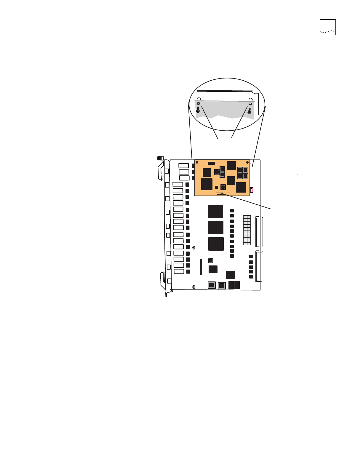
Figure 1-1 shows the DMM with Ethernet carrier, the location of an advanced
Ethernet monitor card (A-ENMC) on the DMM, and Ethernet network monitor
cards (ENMC).
5
Figure 1-1
CoreBuilder 5000 A/DMM with Ethernet Carrier, an Advanced Ethernet
Network Montior Card, and Ethernet Network Monitor Cards
Page 26
1-6
Controller
Module
Network
Monitor
Card
Distributed
Management
Module
Network
Monitor
Card
Network
Monitor
Card
Media
Module
Backplane
Segment 1
Management Bus
Segment 2
Segment n
C
HAPTER
1: I
NTRODUCTION
Figure 1-2 provides an overview of CoreBuilder 5000 hub management.
Figure 1-2
CoreBuilder 5000 Network Management Architecture
In the hub:
■
The controller module exchanges information with all modules through the
management bus.
■
The DMM uses the management bus to send commands to all hub modules
and to collect information from network monitor cards and media modules.
■
Network monitor cards monitor traffic on LAN segments and report the data to
the DMM using the management bus. You must install one NMC for each
network that you are monitoring. You can install ENMCs on either a DMM with
Ethernet carrier or on media modules.
■
Media Modules manage data on LAN segments and receive commands from
the DMM through the management bus.
Page 27

CoreBuilder 5000 Distributed Hub Management1-
7
Ethernet Network
Monitor Card
Description
Advanced Ethernet
Network Monitor Card
Description
CoreBuilder 5000 Ethernet Network Monitor Cards (ENMCs):
■
Monitor activity on Ethernet networks
■
Report this information to the protocol-independent Distributed Management
Module (DMM)
ENMCs reside on CoreBuilder 5000 Ethernet media modules or on the carrier
portion of the DMM-EC.
The ENMC has the following features:
■
Uses the high-speed management bus of the CoreBuilder 5000 hub to
communicate network management information from an Ethernet segment to
the DMM
■
Provides full compliance with the industry-standard RMON MIB
(Internet RFC 1757) to gather RMON-based statistics for modules in the
CoreBuilder 5000 hub
■
Supports N+1 redundancy for fault tolerance, which automatically alerts you to
changes in network operation
The Advanced Ethernet Network Monitor Card (A-ENMC), provides more
processing power than the ENMC. The card employs a Motorola 68040 CPU rated
at approximately 20 MIPS to provide adequate processing capability for
CPU-intensive RMON applications. The card also supports upgradable RAM to
allow for larger statistics tables.
To make full use of the card’s processor, the card hosts two network interfaces.
The A-ENMC requires two CoreBuilder 5000 daughter card connections to provide
these interfaces.
You can use the A-ENMC on a motherboard that has only one daughter card
connector. When you use the A-ENMC on a single-connector motherboard, only
one A-ENMC interface is available for use.
If you back up an A-ENMC with an ENMC, features from the A-ENMC (for
example, security feature) are not supported. If you want A-EMNC full-feature
functionality, then use an A-EMNC for the n + 1 redundancy function.
Page 28

1-8
C
HAPTER
1: I
NTRODUCTION
Token Ring Network
Monitor Card
Description
CoreBuilder 5000 Token Ring Network Monitor Cards (TR-NMCs):
■
Monitor activity on Token Ring networks
■
Report this information to the protocol-independent distributed management
module (DMM)
Each card manages one Token Ring segment. Unlike ENMCs, TR-NMCs reside only
on CoreBuilder 5000 Token Ring Media Modules.
The TR-NMC has the following features:
■
Uses the high-speed management bus of the CoreBuilder 5000 hub to
communicate network management information from a Token Ring segment
to the DMM
■
Complies with the industry-standard IEEE 802.5 MIB (Internet RFC 1231) for
Token Ring networks
■
Complies with the industry-standard RMON-MIB (Internet RFCs 1757
and 1513) to gather RMON-based statistics for networks in the
CoreBuilder 5000 hub
■
Includes Configuration Report Server and Ring Error Monitor functionality to
automatically alert you to changes in ring status, configuration, and
performance
■
Uses REM functionality to track hard and soft errors on the ring
Example DMM
Application
■
Supports N+1 redundancy for fault tolerance, which automatically alerts you to
changes in network operation
If a hub has five Ethernet segments and you want to monitor all five segments
simultaneously, the hub requires:
■
One DMM-EC (with a second DMM if you want a backup for fault-tolerance)
■
Five Ethernet network monitor cards (six if you want a standby NMC for
fault-tolerance)
You can locate network monitor cards either on a DMM equipped with a carrier
option (DMM-EC, for example), or on CoreBuilder 5000 Ethernet media cards.
Token Ring NMCs reside on media modules only.
Page 29

Network Management Functions1-
9
Network Management Functions
The DMM provides the following management and control capabilities:
■
Configurations
— When you are logged in using the administrator or super
user password, you can configure the DMM, as well as network, module, port,
and terminal settings.
■
Staging
— Both the DMM and the media cards save configuration
information. Media cards retain configurations when moved between slots or
hubs. Because of this functionality, you can configure modules at a central
location.
■
DMM Redundancy
— DMMs can trade configuration information, so that
standby DMMs have the same configuration as the active DMM. This allows
standby DMMs to become functional in the event of a failure in the active
DMM.
■
Port Grouping
— DMM supports Port Grouping, so that you can assign sets
of ports to groups. You can then use the group names to manage these sets of
ports simultaneously.
■
Inventory
— The DMM provides a complete inventory of hub contents,
including fans and power supplies. The inventory lists current software revisions
for all installed modules. The Inventory system also supports a scratchpad
feature so that you can add custom information to the DMM display.
■
Fault, Performance, and Traffic Monitoring
— You can set the DMM to
continuously monitor and report key statistics using the MONITOR command.
The statistics on the screen are updated periodically to give a snapshot of the
network. DMM also supports Ethernet repeater statistics without requiring an
NMC card
.
■
CoreBuilder 5000 Token Ring MAC-Address-to-Port Security
— The DMM
can secure your network by comparing station adapter card MAC addresses
against a table that you create. The DMM monitors traffic on each port and
performs the action that you specify when it detects a station whose MAC
address is not included in the table. This process works for Token Ring modules
only.
■
Scripting and Scheduling
— You can create command scripts that execute a
series of user-specified DMM commands. You can also schedule command
scripts to run at predetermined times using the DMM scheduling feature.
■
Power Management
— You can use DMM commands to manage how the
hub handles low power situations. The hub can also provide fault-tolerant
power, which protects against power supply failures.
■
In-band and Out-of-Band Download
— The DMM provides both in-band
and out-of-band downloads. In-band download uses TFTP (Trivial File Transfer
Protocol). Out-of-band download uses XMODEM software and the RS-232
serial port on the front panel of the DMM. You can download to multiple
modules using a single command.
■
SNMP Support
— SNMP (Simple Network Management Protocol) is a protocol
defined by the Internet Engineering Task Force (IETF). The DMM acts as an
agent in an SNMP-managed environment. The agent responds to SNMP
requests and generates SNMP traps.
Page 30

1-10
C
HAPTER
1: I
NTRODUCTION
■
Telnet Support
— You can use the DMM TELNET command to connect a
DMM to any other Telnet device. DMM also supports incoming Telnet sessions
so that you can manage a DMM from a workstation with Telnet support or
from another DMM.
■
SLIP Protocol Support
— Serial Line Interface Protocol (SLIP) provides a
secondary means (using the console port) of connecting the DMM agent to a
hub management network management platform (CoreBuilder 5000 Manager
NCS for UNIX, for example).
■
BOOTP Protocol Support
— BOOTP allows the DMM to request and
download files at startup that configure both new and restarted DMMs
automatically.
■
REM and CRS Support
— Ring Error Monitor (REM) observes, collects, and
analyzes software error conditions. Configuration Report Server (CRS) accepts
commands from IBM LAN manager to get station information, set station
parameters, and remove stations from the ring.
■
RMON Support
— Remote network monitoring (RMON) provides
standards-based SNMP network monitoring functions for use with
management consoles and remote monitors.
■
Dynamically Loadable Modules (DLMs)
support CoreBuilder 5000 Manager LANsentry
— DMM Version v4.0 and later
®
Dynamically Loadable
Modules (DLMs). You must have CoreBuilder 5000 Manager LANsentry
software and the A-ENMC to take advantage of the DLM feature. See the
CoreBuilder 5000 Manager LANsentry Advanced Application User Guide
more information on using DLMs.
for
Page 31

2
D
ESIGNING A
This chapter describes:
■
Understanding CoreBuilder 5000 Management Architecture
■
Understanding CoreBuilder 5000 Management Functions
■
Using Multiple DMMs for Fault Tolerance
■
Network Monitoring Options Using DMM
M
ANAGEMENT
S
YSTEM
Understanding
CoreBuilder 5000
Management
Architecture
Management
Architecture
Components
The CoreBuilder®5000 Integrated System Hub’s management architecture is both
flexible and scalable. This chapter explains the options for building a
CoreBuilder 5000 hub management system.
The management system has these building blocks:
■
Distributed Management Modules (DMMs)
CoreBuilder 5000 hub management system. They:
Contain the 3Com SNMP agent in the hub
■
Provide management and control of the hub
■
The DMM and DMM-EC each occupy a single hub slot. The Advanced
DMM/Controller Module occupies a single slot in the controller bay.
■
Network Monitor Cards (NMCs)
CoreBuilder 5000 hub. They:
Gather statistics about the network to which they are assigned
■
Provide the DMM with IP connectivity to hub network segments (similar to
■
how an adapter card provides connectivity for a PC)
Provide network monitoring support
■
Can provide N+1 redundancy (one extra card backs up all active cards of the
■
same protocol). This feature is not available for TR-NMCs that are located
on module-switched media modules.
— The eyes and ears of the
— The brains of the
■
Network Monitor Card carrier capabilities
install the network monitor cards in the CoreBuilder 5000 hub. They can be
located on the DMM with Ethernet Carrier and on each CoreBuilder 5000
media module.
— The location where you can
Page 32

2-2
C
HAPTER
2: D
ESIGNING A MANAGEMENT SYSTEM
Management
Architecture Options
™
You may also use the following ONline
system concentrator network
management modules in a CoreBuilder 5000 hub:
■
Ethernet Management Module (EMM)
■
Token Ring Management Module (TRMM)
■
FDDI Management Module (FMM)
The role that ONline management plays in a CoreBuilder 5000 hub depends on
how you have implemented CoreBuilder 5000 management. See “ONline System
Concentrator Management Modules in a CoreBuilder 5000 Hub” later in this
chapter for procedures on using ONline management in a CoreBuilder 5000 hub.
Understanding
CoreBuilder 5000
Management
Functions
Through CoreBuilder 5000 hub management, you can scale your network
management configuration to suit the needs of your environment. The system’s
management architecture separates configuration and control from network
connectivity and monitoring. This separation works like a personal computer, using
multiple adapter cards to connect to various networks, rather than integrating
connectivity hardware into the basic system.
Figure 2-1 illustrates DMM network connectivity.
PCs connect to local area networks through
adapter cards.
Adapter Cards
DMMs connect to networks
through Network Moni tor Cards.
Network Monitor Cards
Figure 2-1
Network Connectivity Provided by an NMC
Regardless of how many networks you implement in the hub, you only pay for the
agent once. Purchase only as many Network Monitor Cards as you need to
monitor the networks that you have implemented.
The DMM requires an NMC to connect to a network segment, so you must have
at least one Network Monitor Card if you want to use in-band management.
Page 33

Using Multiple DMMs for Fault Tolerance
2-3
Using Multiple DMMs
for Fault Tolerance
Network Monitoring Options Using DMM
Levels of Monitoring
Each CoreBuilder 5000 hub can support more than one DMM. When you add
additional DMMs, one DMM becomes hub master, while the additional DMMs
enter standby mode.
The controller module selects a master management module by determining
which DMM has the highest mastership priority. This mastership priority is
user-settable. If two DMMs have equal mastership priority, the election is arbitrary.
If the master DMM fails, a mastership election occurs and the DMM with the
next-highest mastership priority assumes the role of hub master. In DMM Version
v2.3 and later, a standby DMM can store and retrieve enough information to
assume the same configuration as the failed master.
You can use several approaches to monitor networks in a CoreBuilder 5000 hub.
The option you choose depends on the following factors:
■
The level of monitoring that you require
■
Whether or not you want fault-tolerant network monitoring
■
Whether or not you want to incorporate ONline system concentrator
management modules in the system
There are two possible approaches to network monitoring:
■
Using one NMC for multiple networks
■
Using one NMC per network
Using One NMC for Multiple Networks
This low-cost option allows you to monitor only one of your installed networks at
a time:
■
Advantage: Need to buy only one NMC per hub
■
Disadvantages:
Must switch the connection from network to network manually
■
May have one or more networks that are not being monitored
■
May make monitoring networks using SNMP more difficult because every
■
time that you move an NMC to a different network, there is a danger of
losing remote connectivity with the DMM
Using One NMC per Network
This configuration allows you to monitor all network segments simultaneously:
■
Advantages:
Full statistics on all networks simultaneously
■
Simplified network connectivity
■
■
Disadvantage: Somewhat higher cost than using fewer cards
Page 34

2-4
C
HAPTER
2: D
ESIGNING A MANAGEMENT SYSTEM
Incorporating N+1 NMCs
for Fault-Tolerance
ONline System
Concentrator
Management Modules
in a CoreBuilder 5000
Hub
If you want fault-tolerant network monitoring in the hub, install one more NMC
than you require (n cards, plus 1) to monitor the networks that you have
implemented. The spare NMC assumes the role of a failed NMC. This NMC has its
network interface set to Standby mode.
If you back up an A-ENMC with an ENMC, features from the A-ENMC (for
example, security feature) are not supported. If you want A-EMNC full-feature
functionality, then use an A-EMNC for the n + 1 redundancy function.
Use ONline System Concentrator management modules in a CoreBuilder 5000
hub to protect your investment in ONline modules. You can use ONline System
Concentrator management modules to monitor the ONline-compatible networks
in your hub.
Ethernet Network Monitor Cards can monitor any Ethernet network statistic,
including RMON, in a CoreBuilder 5000 hub. ONline management modules can
manage ONline-compatible networks only. Token Ring NMCs can monitor
CoreBuilder 5000 Token Ring networks only.
Table 2-1 shows the scenarios for using ONline management modules in a
CoreBuilder 5000 hub.
Ta b l e 2 - 1
ONline Management Modules in a CoreBuilder 5000 Hub
Configuration Resulting Role of ONline Management Module
No DMM Present
DMM Present
Same role as in ONline™ System Concentrator. Can configure and
monitor all ONline modules. If TRMM Version v2.1 or later, or EMM
Version 4.0 or later, can provide hub status as well. Cannot manage
CoreBuilder
Can monitor traffic on the network segment to which it is assigned.
However, you must connect using the console port (or using SNMP)
because ONline management modules do not send information to
the DMM.
®
5000 modules.
CoreBuilder 5000 and ONline Token Ring modules operate on separate
backplanes. Therefore, you must install TRMM modules to monitor ONline Token
Ring networks in a CoreBuilder 5000 hub.
Page 35

U
NPACKING AND INSTALLING THE
3
Precautionary Procedures
M
ODULE
This chapter describes unpacking and installation procedures for the 3Com
CoreBuilder
■
Precautionary Procedures
■
Unpacking Procedures
■
Preinstallation Procedures
■
Installing the DMM or DMM-EC Modules
■
Using the Module Front Panel
Electrostatic discharge (ESD) can damage the static-sensitive devices on circuit
boards. To avoid this kind of damage, use the following precautions when
handling the DMM:
Follow the procedures in this section carefully to avoid damage to your
equipment.
®
5000 Distributed Management Module (DMM). The sections are:
Unpacking Procedures
■
Do not remove the board from its antistatic bag until you are ready to insert it
into the hub.
■
Before you handle the DMM, use proper grounding techniques when you
inspect and install the DMM. Use a foot strap and grounded mat, wear a
grounded static discharge wrist strap, or touch a grounded rack or other source
of ground.
To unpack the distributed management module (DMM):
Verify that the DMM is the correct model by matching the model number on the
1
side of the shipping carton to the model number that you ordered.
■
Model Number 6000M-MGT
■
Model Number 6000M-CMGT
■
Model Number 6106M-MGT —
Remove the module, in its antistatic bag, from the shipping carton.
2
Remove the module from the antistatic bag and inspect it for damage. Always
3
handle the module by the front panel being careful not to touch the components.
If the module appears to be damaged, replace it in the antistatic bag, return it to
the shipping carton, and contact your supplier.
Complete and mail the self-addressed Customer Registration Card. No postage is
4
necessary if mailed in the United States. If you are returning the card from outside
of the U.S.A., be sure to apply the correct postage.
— DMM
— Advanced DMM/Controller Module
DMM with Ethernet Carrier (DMM EC)
Page 36
3-2
C
HAPTER
3: U
NPACKING AND INSTALLING THE MODULE
Preinstallation Procedures
Switching the Auxiliary
Port to RS-423 Mode
Before you install the module, read the following sections:
■
Switching the Auxiliary Port to RS-423 Mode
■
Installing an Ethernet Network Monitor Card
■
Installing an Advanced Ethernet Network Monitor Card
■
Installing a Token Ring Network Monitor Card
An onboard jumper sets the Auxiliary DB-9 connector on the module to either
RS-232 (the factory default) or RS-423 protocol. These jumper settings are neither
software detectable nor software controllable.
To switch the auxiliary port to RS-423 mode:
■
DMM and DMM-EC
■
Advanced DMM/Controller Module
— Position jumpers JP8 and JP9 as shown in Figure 3-1.
— Position jumpers JP1 and JP2 as
shown in Figure 3-2.
Figure 3-1 shows the RS-232/RS-423 jumper settings.
Upper RS-432 mode
jumper pins
Figure 3-1
423
JP8
232
Jumper lower pins
for RS-232 mode
Insert Jumper JP9 for RS-432 mode
Setting the RS-232/RS-423 Jumpers (DMM and DMM-EC)
Page 37
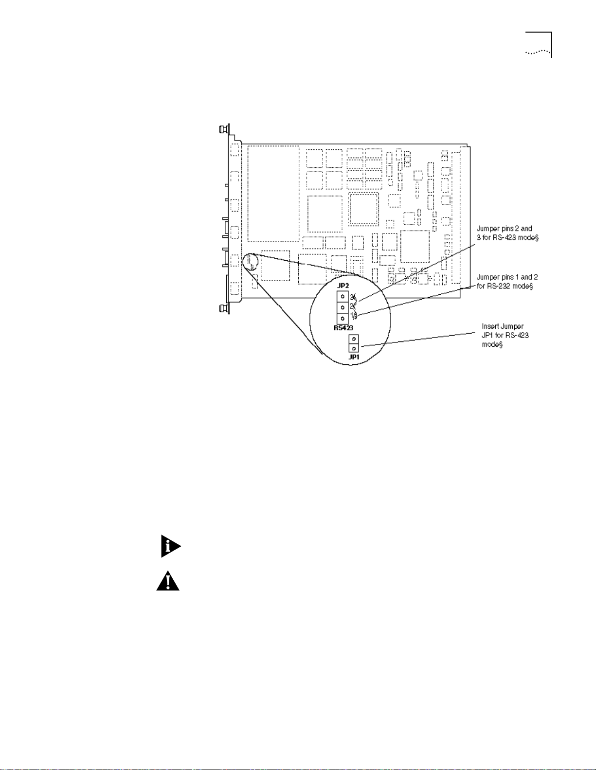
Preinstallation Procedures
3-3
Figure 3-2 shows jumper positions JP1 and JP2 on the Advanced DMM/Controller
Module.
Installing an Ethernet
Network Monitor Card
Figure 3-2
Setting the RS-232/RS-423 Jumpers (Advanced DMM/Controller Module)
To install an Ethernet Network Monitor Card (ENMC) on a CoreBuilder 5000
Ethernet Media Module or on a Distributed Management Module with Ethernet
Carrier (DMM-EC) (Figure 3-3):
Match the ENMC connector pins to the corresponding pins on the host
1
CoreBuilder 5000 Ethernet Media Module or CoreBuilder 5000 DMM.
Seat the ENMC connector into the media module or DMM-EC connector.
2
Secure the ENMC to the media module or DMM-EC by screwing down the
3
standoffs near the card edge that is opposite the connector. Do not overtighten.
The connector on the non-carrier DMM (stand-alone) is reserved for future use. It
does not support a network monitor card.
CAUTION:
You cannot install a Network Monitor Card (NMC) without removing
the board that is carrying the NMC. You cannot, for example, reach into the hub
and install an NMC on an installed media module. Doing so causes damage to the
card because the NMC depends on its carrying card for power-on surge
protection.
Page 38
3-4
C
HAPTER
3: U
NPACKING AND INSTALLING THE MODULE
Figure 3-3 shows how to install a network monitor card on a CoreBuilder 5000
module on a 24-Port 10BASE-T module.
Figure 3-3
Monitor card
Standoff
Standoff
ENMC connector
Installing a CoreBuilder 5000 Ethernet Network Monitor Card
Installing an Advanced
ENMC
Installing a Token Ring
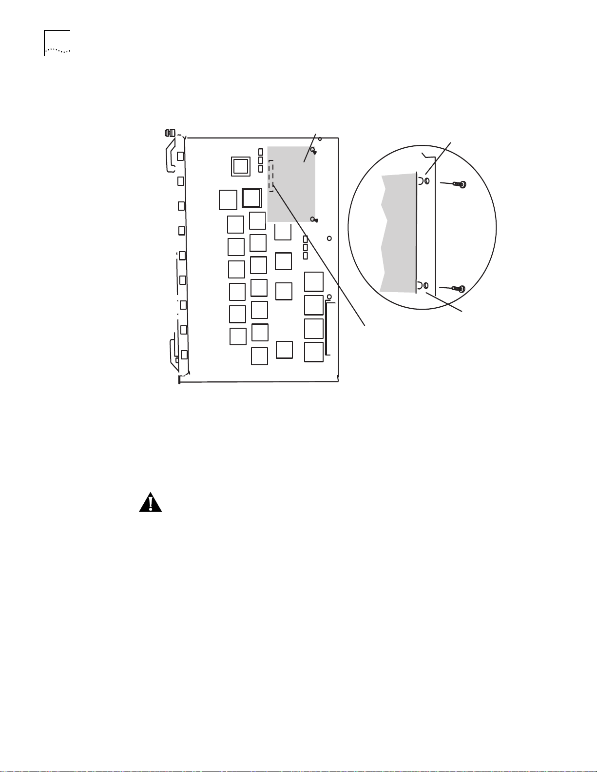
NMC
See the installation instructions (Part Number 17-00690) that are included with
the A-ENMC.
This section describes how to install a Token Ring NMC.
CAUTION:
You cannot install a Network Monitor Card (NMC) without removing
the board that is carrying the NMC. You cannot, for example, reach into the hub
and install an NMC on an installed media module. Doing so causes damage to the
card because the NMC depends on its carrying card for power-on surge
protection.
To install a TR-NMC on a CoreBuilder 5000 Token Ring Media Module
(Figure 3-4):
Match the TR-NMC 50-pin connector to the corresponding connector on the host
1
CoreBuilder 5000 Token Ring Media Module. Make sure that the holes align with
the standoffs on the media module.
Seat the TR-NMC connector onto the media module connector.
2
Secure the TR-NMC to the media module by screwing down the two standoffs
3
opposite the connector (Figure 3-4). Do not overtighten.
Page 39
Installing the DMM or DMM-EC Modules
3-5
Figure 3-4 shows how to install a Token Ring NMC. The orientation of the NMC on
the Token Ring module varies, but the relationship of the card to the standoffs is
always the same.
Standoffs
OFF
ON
SW1
sw2
sw3
sw4
sw5
sw6
sw7
sw8
Installing the DMM or
DMM-EC Modules
Hot Swapping
Connector
Figure 3-4
Installing a CoreBuilder 5000 Token Ring NMC
This section describes how to install the CoreBuilder 5000 Distributed
Management Module (DMM) and the Distributed Management Module Ethernet
carrier (DMM-EC). For instructions on installing the Advanced DMM/Controller
Module, see the
CoreBuilder 5000 Advanced DMM/Controller Module Quick Start
(Part Number 10011858).
You do not need to power off the hub to install the DMM. The DMM, like all other
3Com CoreBuilder 5000 modules (except NMCs), can be hot-swapped. That is,
you can install the module into any open slot and remove it while the hub is
operating.
Page 40
3-6
C
HAPTER
3: U
NPACKING AND INSTALLING THE MODULE
Installing the DMM
When you first install a new CoreBuilder 5000 hub with a single DMM or
DMM-EC and other media modules, complete the following steps. If you are
installing a single DMM or DMM-EC into a previously unmanaged hub, omit any
steps that do not apply directly to the DMM or DMM-EC:
Install the hub in its location (in a rack or on a table), according to the instructions
1
CoreBuilder 5000 Integrated System Hub Installation and Operation Guide.
in the
If a DMM or DMM-EC is installed into a powered down hub that already has one
or more DMM, DMM-EC, or A/DMMs installed, the new DMM could become the
hub master and reconfigure the others to factory defaults upon powering up. For
this reason, if the new module is intended to be a redundant slave, always install it
into the hub with the power on, and an existing master. If you intend the new
module to configure the existing ones, see Chapter 5, “Using the DMM for
Network Administration
Insert the fault-tolerant controller module, the media modules, and the DMM or
2
DMM-EC module into the board guides at the top
.”
and
bottom of the slots and
slide them into the hub.
Secure each module into the hub using the ejector arms to secure the module to
3
its backplane connection.
CAUTION:
Do not use excessive force to insert the modules into the backplane. If
a module does not easily slide into the hub, it could cause permanent damage to
the module or the hub.
Verifying Operation
Fasten the spring-loaded screws on the front panels of the modules to the hub
4
with your fingers. Do not overtighten.
Connect the power to the power supply, apply the power to the hub, and proceed
5
to Verifying Operation next.
See the
Guide
CoreBuilder 5000 Integrated System Hub Installation and Operation
for detailed instructions on inserting modules into the hub.
This section explains how to verify DMM operation before you enter commands:
■
The Status LED on the module is solid green.
■
The LED character display displays
if this module is master
Rdy
■
■
Stby
if this module is a backup
, and then it displays either:
Diag
The following message appears on the terminal screen after the module is
installed properly and the RS-232 connection is made:
CoreBuilder 5000 Distributed Management Module (vx.xx)
Copyright (c) 199x 3Com Corporation.
See Chapter 4, “Configuring the DMM”, for instructions on configuring your
terminal to work with the DMM.
Page 41

Using the Module Front Panel
3-7
Using the Module
Front Panel
This section describes the front panel for the DMM, DMM-EC, and Advanced
DMM/Controller Module.
Front panels for all models have:
■
Four-character display with a display control toggle switch
■
Module reset button
■
Two serial port connectors (used to connect the DMM to a terminal or modem)
The DMM and DMM-EC front panels include a module status LED.
The DMM-EC front panel includes Ethernet status LEDs.
To support hub controller functions, the Advanced DMM/Controller Module front
panel includes:
■
Active and Standby LEDs
■
LED Test button
■
Hub Reset button
See Figure 3-5 and Figure 3-6.
For information on controller functions, see the
DMM/Controller Module Quick Start and Reference
CoreBuilder 5000 Advanced
.
Page 42

3-8
C
HAPTER
3: U
NPACKING AND INSTALLING THE MODULE
DMM-EC and DMM
Front Panel Components
Figure 3-5 shows the front panel components on the DMM-EC and DMM.
STATUS
STATUS
MODULE
SYSTEM
DISPLAY
D
C
O
N
MODULE
RESET
NETWORK
STATUS
1
2
3
4
5
6
7
8
Module Status LED
Character display
IS
P
L
A
T
Y
R
O
L
Display control
Module Reset button
Ethernet
Status
LEDs
MODULE
SYSTEM
DISPLAY
DISPLAY
CONTROL
MODULE
RESET
Figure 3-5
Console port
RS-232
LOCAL
CONSOLE
Auxiliary port
RS-232/423
REMOTE
CONSOLE
6106M-MGT
DMM-EC and DMM Front Panels
RS-232
CONSOLE
RS-232/423
AUXILIARY
DMM
Page 43

Using the Module Front Panel
3-9
A/DMM Controller
Module Front Panel
Components
Figure 3-6 shows the front panel components on the A/DMM controller module.
A
C
S
T
T
IV
B
Y
E
Character display
Display button
IS
P
DMM reset button
M
M
E
T
LED test button
E
D
T
Hub reset button
U
B
E
T
Active LED
Standby LED
DISPLAY
R
E
T
E
R
E
D
D
S
L
S
H
S
Figure 3-6
Console port
RS-232
Auxiliary port
AUX
DMM-CTLR
Advanced DMM/Controller Module Front Panel
Page 44

3-10
C
HAPTER
3: U
NPACKING AND INSTALLING THE MODULE
Module Status LED
Character Display and
Display Button
Table 3-1 describes the DMM Status LED.
Ta b l e 3 - 1
LED Name Color State Indicates
Status Green Off Power off or complete module failure
DMM Status LED Description
On Power on and software functioning
properly
Blinking Power on, but diagnostics have failed
The character display indicates:
■
The current operating state of the module.
■
The network assignment of ports, connectors, and modules in the hub.
■
The version number of the DMM-embedded software.
■
Any environmental fault. (For example, when a power supply, fan, or overheat
fault occurs, the fault appears in the character display.)
The default display is the module operating state.
To use the display button:
Press the Display button. Press the button repeatedly to toggle the display through
1
all active networks in the hub.
The status LEDs light for all modules, connectors, or ports that are assigned to the
network indicated on the display. For example, when the display indicates
E1
of the status LEDs for ports and modules assigned to backplane network Ethernet
1 light.
After you have toggled the display through all available backplane and isolated
2
Vers
networks, the
Approximately 1 second after
3
(version) is shown.
Vers
appears, the display shows the version number
of the embedded DMM software.
All isolated networks are grouped when you use Ethernet Isolated (EI), Token Ring
Isolated (TRI), or FDDI Isolated (FI).
Table 3-2 describes text that can appear in the DMM LED display.
Ta b l e 3 - 2
Display Definition
Diag DMM is running system diagnostic tests.
Stby DMM is in standby (inactive) mode.
Rdy DMM is the active management module for the hub.
E1 to E8, EI Status LEDs light for Ethernet 1 through 8 (active only) or isolated (EI).
TR1 to TR10,
TRI
F1 to F4, FI Status LEDs light for FDDI 1 through 4 (active only) or isolated (FI).
Vers Displays version number of the DMM-embedded software.
LED Controller-initiated LED test.
DNLD Each time a download is initiated from the DMM.
DMM LED Display
Status LEDs light for Token Ring 1 through 10 (active only) or isolated (TRI).
, all
Page 45

Using the Module Front Panel
3-11
DMM Reset Button
Ta b l e 3 - 2
Display Definition
TEMP Temperature in the hub is higher than the allowable limit.
FANn
(n = 1 to 3
PWRn
(n = 1 to 4)
DMM LED Display (continued)
Fan unit is malfunctioning or not operational.
Power supplies are installed but faulty.
The DMM Reset button resets the DMM and executes self-test diagnostics;
network traffic is not affected. The Reset button is recessed to prevent an
accidental reset. You can press the button with a pen tip or a small screwdriver.
Press the DMM Reset button only if you suspect a problem with the DMM.
Before you reset the module, issue the SAVE ALL command. When you reset the
DMM, it configures itself using the last-saved configuration parameters.
For the DMM and DMM-EC module, pushing the DMM Reset button has the same
effect as issuing the RESET DEVICE command. For the A/DMM controller, pushing
the reset button is similar to issuing a RESET DEVICE command, except that the
A/DMM controller cold boots and runs the full cold boot diagnostic test, if
diagnostics are enabled. You enable diagnostics using the SET DEVICE command.
Ethernet Network LEDs
Pressing the DMM Reset button results in a hard-reset (not a soft-reset).
The DMM-EC has three columns of LEDs that display the status of the eight
available Ethernet channels in the CoreBuilder 5000 hub. Table 3-3 describes the
function of each DMM-EC LED.
Ta b l e 3 - 3
LED Name Color On/Off Indicates
Channel Monitor Green On Network has an Ethernet Network
Activity Yellow Blinking Packets are traveling on this network.
Collision Yellow Blinking Collisions are occurring on this network.
Interpretation of Ethernet Status LEDs
Monitor Card assigned to it.
Off No ENMC is allocated to this network.
Blinking Fault is detected on this network.
Off No traffic on this network.
Off No collisions on this network.
Page 46

3-12
C
HAPTER
3: U
NPACKING AND INSTALLING THE MODULE
RS-232 Console and
Auxiliary Ports
This section describes:
■
Connecting to a Terminal or Modem
■
Using a Modem
Connecting to a Terminal or Modem
To connect the DMM to a terminal (either port) or modem, use the RS-232
Console Port and RS-232/423 Auxiliary Port connectors. You can enter
management commands and download new software using these ports.
■
The DMM and DMM-EC use 9-pin (DB-9) DTE male connectors.
■
The A/DMM controller uses micro 9-pin connectors. This module is shipped
with an adapter cable that converts the micro 9-pin connector to a DB-9 male
connector with a pinout identical to the DMM and DMM-EC connectors.
Table 3-4 and Table 3-5 show the console and auxiliary port pinouts.
Ta b l e 3 - 4
Pin Step Next Signal Name
1 Carrier Detect (CD)
2 Receive Data (RX)
3 Transmit Data (TX)
4 Data Terminal Ready (DTR)
5 Signal Ground (GND)
6 Data Set Ready (DSR)
7 Request to Send (RTS)
8 Clear to Send (CTS)
9 no connection
Console Port Pinouts
Ta b l e 3 - 5
Pin Step Next Signal Name
1 Carrier Detect (CD)
2 Receive Data Plus (RX+)
3 Transmit Data (TX)
4 Data Terminal Ready (DTR)
5 Signal Ground (GND)
6 Data Set Ready (DSR)
7 Request to Send (RTS)
8 Clear to Send (CTS)
9 Receive Data Minus (RX-) if RS-423;
Auxiliary Port Pinouts
otherwise, no connection
Page 47

Using the Module Front Panel
3-13
Table 3-6 shows 9-pin to 9-pin assignments for connecting your PC to the front
panel of the DMM.
Ta b l e 3 - 6
Signal DMM Pin Step Next DTE Pin Step Next Signal
CD 1 N/A not used
RX 2 3 TX
TX 3 2 RX
DTR 4 6 DSR
GND 5 5 GND
DSR 6 4 DTR
RTS 7 8 CTS
CTS 8 7 RTS
Not used 9 N/A not used
RS-232 9-Pin to 9-Pin Cable Connection Pin Assignments
Table 3-7 shows 9-pin to 25-pin assignments for connecting your PC to the front
panel of the DMM.
Ta b l e 3 - 7
Signal DMM Pin Step Next DTE Pin Step Next Signal
CD 1 N/A not used
RX 2 2 TX
TX 3 3 RX
DTR 4 6 DSR
GND 5 7 GND
DSR 6 20 DTR
RTS 7 5 CTS
CTS 8 4 RTS
Not used 9 N/A not used
RS-232 9-Pin to 25-Pin Cable Connection Pin Assignments
Using a Modem
To configure the DMM Console Port for dial-in modem use:
Ensure that the modem is 100 percent Hayes-compatible.
1
Select any of theses baud rates: 300, 1200, 2400, 4800, 9600, 19200, 38400. The
2
factory default is 9600.
Page 48

3-14
C
HAPTER
3: U
NPACKING AND INSTALLING THE MODULE
Place the modem in Dumb/Auto Answer mode. To do this, enter the commands
3
listed in Table 3-8 from a terminal that is directly connected to the modem. Press
the Enter key after each command.
Ta b l e 3 - 8
Command
a
b* at&d0 Ignore changes in DTR status
c ats0=1 Auto-answer on first ring
d ats0? Verify auto-answer (should return 001)
e atq1 Does not return result codes
f ate0 Does not echo characters in command state
g at&W Save this configuration
h at&Y Define this configuration as default
* If you issue the SET TERMINAL HANGUP ENABLE command for modem use, you must change the DTR
parameter as follows to ensure proper modem operation:
Modem Commands Required for Console Ports
Data Terminal
Ready (DTR)
Parameter
at&F
Function
Restore factory defaults
Data Terminal
Ready (DTR)
Command
b at&d2 Indicates hangup and assumes command state
Parameter
Function
when an On to Off transition of DTR occurs
Page 49

4
C
ONFIGURING THE
This chapter describes how to configure an installed 3Com CoreBuilder® 5000
DMM and A/DMM. This chapter contains the following sections:
■
Quick Reference for Configuring the DMM
■
Configuring the Terminal
■
Configuring User Logins
■
Configuring the DMM
■
Configuring the TR-NMC
■
Setting SNMP Values
■
Making In-band Connections
■
Setting Up Network Monitoring
■
Saving Configuration Values
DMM
■
Logging Out
■
Adding a Second DMM for Fault Tolerance
DMM commands and conventions are described in the
Distributed Management Module Commands Guide
guide before you configure your DMM. After you are familiar with DMM
command conventions, see the
Module Command Reference
CoreBuilder 5000 Distributed Management
for the commands to configure your DMM.
CoreBuilder 5000
. Review the commands
Page 50

4-2
C
HAPTER
4: C
ONFIGURING THE
DMM
Quick Reference for Configuring the DMM
Table 4-1 outlines the steps for configuring your DMM
Ta b l e 4 - 1
Task* Command
1. Configure your terminal to default DMM communication
settings
2. Configure DMM Terminal Settings SET TERMINAL HANGUP
3. Configure the hub SET CLOCK
4. Configure the DMM SET DEVICE CONTACT
5. Configure SNMP SET IP SUBNET_MASK
*
The order of configuration is important in some networks. Read the appropriate sections for more
information.
Quick Reference for Configuring the DMM
See your terminal vendor’s
documentation
SET TERMINAL PROMPT
SET TERMINAL TIMEOUT
SET DEVICE DIAGNOSTICS
SET DEVICE LOCATION
SET DEVICE NAME
SET IP DEFAULT_GATEWAY
SET IP IP_ADDRESS
SET COMMUNITY
SET ALERT
SET DEVICE TRAP_RECEIVE
Configuring the Te rm in a l
Configuring the Terminal
to Default Settings
This section describes:
■
Configuring the Terminal to Default Settings
■
Changing the Terminal Configuration
■
Customizing Terminal Settings
You must configure your terminal to the serial port on the DMM to the same
parameter settings as the DMM. Doing so allows the terminal and DMM to
communicate. Initially, the terminal settings must match the factory-default
settings of the DMM as specified in Table 4-2.
To configure the terminal:
Consult the user guide that is shipped with your terminal for instructions on
1
setting the terminal values.
Ta b l e 4 - 2
Parameter
(SET TERMINAL +)
Baud 300, 1200, 2400, 4800, 9600, 19200, 38400 9600
Data_bits 7 or 8 8
Parity odd, even, or none none
Stop_bits 1 or 2 1
Terminal Defaults and DMM Options
DMM Options (After Connection) Factory Default
Page 51

Configuring the Terminal
After you have configured your terminal to match the DMM’s factory defaults,
2
press Enter. The following message appears:
Distributed Management Module (vx.xx)
Copyright (c) 199x 3Com Corporation
At the Login prompt, enter a login name and press Enter. (The default login name
3
system
is
Enter the password and press Enter. (The default password is the Enter key.) The
4
.) The DMM prompts you for a password.
DMM displays the following message and prompt:
Welcome to super user service on CB5000.
CB5000>
You are now logged in as the super user with full access to all commands.
After terminal settings are complete, you can configure the CoreBuilder 5000 hub,
the newly installed DMM, and all other CoreBuilder 5000 SwitchModules in the
hub.
To show the current terminal settings, use the SHOW TERMINAL command.
4-3
Changing the Terminal
Configuration
Customizing Terminal
Settings
To change the terminal configuration, use the SET TERMINAL command using the
DMM options from Table 4-2.
The syntax for the command is:
set terminal <port> <option>
Where <port> is either CONSOLE or AUXILIARY and the options are as listed in
Table 4-2. After you enter each new SET TERMINAL command (changing the baud
rate, for example), you must change the settings for the terminal to match the
new setting before you can reestablish communication.
You can change the following optional terminal management settings to
customize your terminal connection:
■
Terminal hangup
■
Terminal prompt
■
Terminal timeout value
■
Terminal type
■
Console or auxiliary port for SLIP operation
These terminal settings are optional, and apply to both terminal ports. Enter the
SAVE TERMINAL command to save any changes that you make to terminal
parameters.
Setting Terminal Hangup
Use the SET TERMINAL HANGUP command if you use a modem connection to log
in to the DMM. This command causes the modem to hang up the connection to
the terminal automatically when you log out of the DMM. Hanging up the
connection helps prevent unauthorized access.
The default for the SET TERMINAL HANGUP command is DISABLE. When the
command is set to DISABLE, the modem does not automatically hang up when
you log out of the connection.
Page 52

4-4
C
HAPTER
4: C
ONFIGURING THE
DMM
To hang up the modem connection automatically when you log out of the DMM,
use the SET TERMINAL HANGUP command as shown:
CB5000> set terminal hangup enable
Terminal hangup asserts and deasserts the RS-232 Data Terminal Ready (DTR)
signal (pin 20). When you complete a call, the DTR signal deasserts to properly
terminate that connection. If Terminal Hangup is disabled, the DTR signal remains
asserted. Thus, you may receive an incoming call, but the system does not
terminate the connection automatically.
Setting Terminal Prompt
Use the SET TERMINAL PROMPT command to customize the terminal prompt for
each DMM. Use this prompt to identify the DMM that you are connected to when
logged in to a remote DMM. The default is
CB5000>
.
To customize your terminal prompt, use the SET TERMINAL PROMPT command as
shown:
CB5000> set terminal prompt DMM3>
To avoid confusion, use the same identification for both the terminal prompt and
the device name of your DMM.
Setting Terminal Timeout Value
Use the SET TERMINAL TIMEOUT to specify the amount of time that you want
your terminal to remain active during the absence of any keyboard activity. Use
this feature to keep unauthorized users off of the system if you leave your terminal
without logging out.
The default for the command is 0, which means that no timeout has been set so
that you never are logged out automatically.
To set the timeout period (value expressed in minutes), use the SET TERMINAL
TIMEOUT command as shown:
CB5000> set terminal ti meout 10
After you set the timeout, the terminal automatically logs you off the system if
there is no terminal (keyboard) activity for the period of time that you specified.
Any unsaved changes that you made before the timeout remain unsaved. You
must log back into the DMM to save these changes. If the DMM resets before you
save the changes, the changes are lost.
Setting Terminal Type
Use the SET TERMINAL TYPE command to define a terminal type for use with
outbound Telnet sessions. The system sends the terminal type to the device
connected to the DMM when initiating the Telnet session. The terminal type
setting enables the device to send the proper control sequences to the DMM,
which are displayed on the DMM terminal.
The following command defines the terminal type as a VT100 terminal:
CB5000> set terminal terminal_type vt100
Terminal type changed.
Page 53

Configuring the Terminal
CB5000> set ip subnet_mask ff.ff.ff.00 slip
CB5000> set ip ip_address 151.104.20.84 slip
CB5000> set terminal auxiliary baud 38400
CB5000> set terminal auxiliary data_bits 8
CB5000> set terminal auxiliary parity none
CB5000> set terminal auxiliary stop_bits 1
CB5000> set community my_system 151.104.20.83 all
CB5000> set terminal auxiliary mode slip 151.104.20.83
SLIP network activated!
Setting the Console or Auxiliary Port for SLIP Operation
You can configure a Serial Line Internet Protocol (SLIP) connection on either the
DMM console port or the DMM auxiliary port. SLIP allows TCP/IP connections over
a serial line.
Using the SLIP feature in the CoreBuilder 5000 hub, you can connect the following
to a DMM serial port:
■
A workstation running network management software, either locally or using a
modem
■
A PC using a modem
Vendors initiate SLIP sessions differently. Consult the documentation for your
system. Although the 3Com SLIP implementation is as generic as possible, it may
not function properly with SLIP implementations from other vendors.
To open (start) a SLIP session, enter the following commands either from the port
that will
SET IP SUBNET_MASK <mask> SLIP (where <mask> is the workstation’s IP subnet):
1
■
not
be used for SLIP or through a Telnet session:
Set data bits to 8
4-5
■
Set baud rate as high as the hardware supports
SET IP IP_ADDRESS <address> SLIP (where <address> is the DMM’s IP address)
2
SET TERMINAL <port> <baud, data_bits, parity, stop_bits> (as appropriate for the
3
serial connection running SLIP)
SET TERMINAL <port> MODE SLIP <address> (where <address> is the
4
workstation’s IP address).
To end the SLIP session and return the SLIP port to command line mode, use an
appropriate break sequence.
The following commands are an example of setting the port mode to SLIP on the
DMM auxiliary port:
You cannot perform module software downloads from a SLIP connection.
Page 54

4-6
C
HAPTER
4: C
ONFIGURING THE
DMM
Configuring User Logins
User Access Levels
This section describes:
■
User Access Levels
■
User Login Functions
■
Adding New Users
■
Showing Current Users
■
Clearing Login Names
You must be logged in using a user name that has been assigned super user
privileges to add login names. The default login name is
system
, with no
password (that is, press Enter at the password prompt).
DMM provides three levels of user access:
■
User Level
— The user can display information about network configuration
and operation (except community table information).
■
Administrator Level
Perform all user-level tasks
■
Reset and configure CoreBuilder 5000 modules and ports (SET commands)
■
■
Super User Level
— The user can:
—The user can perform administrator-level and user-level
tasks, enter maintenance mode, and add and change passwords, as well as:
User Login Functions
Configure hub IP address information
■
Configure community tables
■
Download new flash and boot code
■
The DMM allows:
■
Configuration of up to 10 user logins, in any combination of access levels
■
More than one user at a time to log in to the command interface
Login Limitations
Only one user at a time can log in with write privileges. If a second administrator
or super user tries to log in, that user has access to user-level (read) functions only.
Up to four remote (Telnet) sessions can be established at one time.
Super User Access
Because the DMM allows only one super user login at a time, the software
includes a special SET LOGIN ACCESS SUPER_USER command. If a super user logs
in and is granted only user privileges, that user can issue the SET LOGIN ACCESS
SUPER_USER command with the following implications:
■
The current super user is logged off the DMM
■
The super user that enters the command immediately assumes super user
privileges
■
The new super user assumes responsibility for all unsaved changes from the
logged out super user session
Page 55

Configuring User Logins
4-7
This command can also override sessions in which communications have failed,
but the super user remains logged in. Without this command, you must wait for
the disrupted super user session to time out before you are allowed to initiate a
new super user session.
Adding New Users
As stated in the previous section, DMM allows you to configure up to 10 user
logins, with access rights as described previously.
To add a new user, you must have super user access.
To add a new user:
Log in using a super user-level name and password.
1
At the
2
set login <
Where <l
CB5000>
ogin type>
admini st ra to r
prompt, enter:
login type
is the type of user you are adding:
.
>
user, super_user
The system prompts you for your password (to confirm your right to set new
passwords) as follows:
CB5000> Enter current session password for user “system”:
3
At the
Enter Lo gi n Na me:
prompt, enter the login name for the user who you
want to add.
At the
4
At the
5
To save the new user login, enter the SAVE LOGIN command.
6
Enter Lo gi n Pa ssword:
Verify - re-enter passwo rd:
prompt, enter the login password.
prompt, retype the new password.
, or
Showing Current Users
The system acknowledges the new password by displaying the following:
CB5000>Login successfully ente red.
To show the existing login names for the DMM, enter the SHOW LOGIN
command. The following information appears:
Index Logi nN am e Acces s Activ e Se ssi ons
------ ------------------- ----------------------------1 system Super User 1
2 kwillow User 0
3 test1 User 0
4 [not used]
5 [not used]
6 [not used]
7 [not used]
8 [not used]
9 [not used]
10 [not used]
Active Login Sessions:
LoginName Session Type Session Time
---------- --------------- --------------system Remote Super User 0 days 00:08:05
system Remote User 1 days 01:08:06
Page 56

4-8
C
HAPTER
4: C
ONFIGURING THE
DMM
Table 4-3 describes the fields in the SHOW LOGIN display.
Ta b l e 4 - 3
Column Description
Index Index number of each of the 10 available logins
LoginName Name assigned to each login (or [not used])
Access Privilege level assigned to this login name. See User Access Levels
Active Sessions Number of active sessions under this login name
Active Login Sessions Session Type — Indicates user privileges and whether session is local
SHOW LOGIN Display Descriptions
earlier in this chapter for definitions.
or remote
Session Time — Length of the session
Clearing Login Names
Configuring the DMM
You may want to clear login names from the DMM periodically to help ensure
system security.
To clear a login name from the DMM, enter:
CB5000> clear login <index number>
or
CB5000> clear login all
to clear all logins that are not currently logged in with Active Sessions.
If you are not sure of the index number for the user name that you want to clear,
enter the SHOW LOGIN command for a list of all login names (and corresponding
index numbers) available for this DMM.
This section describes the commands necessary for startup and management of
your DMM, hub, and media modules:
■
Configuring the Internal Clock
■
Configuring the DMM Device
This section outlines the commands to identify the hub platform for your DMM
and for setting the internal clock.
Configuring the Internal
Clock
Use the SET CLOCK command when you install the DMM into your hub to
establish a starting time, date, and day. Define this setting only once, because
changing the clock setting may affect real-time statistics gathering.
To set the 24-hour internal clock to
CB5000> set clock 17:58 99/03/20 saturday
5:58PM, Saturday, March 20th, 1999,
enter:
The internal clock is powered by its own battery and continues to work even if the
hub loses power. Even when the module is powered off, this battery is designed to
operate for 10 years. You do not need to issue a SAVE command to save clock
settings.
When you set the clock on the management module master, the master teaches
the time to all management module slaves. However, if you set the clock on a
management module slave, only the slave’s time is reset. After a moment or two,
the master resynchronizes the slave’s time with that of the master clock.
Page 57

Configuring the DMM
4-9
Configuring the DMM
Device
This section describes the required configuration settings for your DMM. The
DMM is factory-set to default values that you may need to change before you use
it (for example, the mastership priority of the DMM).
You must set the following configuration values for your DMM:
■
DMM Name
■
Diagnostics
■
Service Contact Name and Location
Assigning the DMM a Name
Assign a unique name to each DMM. You can use this name instead of the IP or
MAC address to reference a particular DMM (for example, when using Telnet).
To assign a unique name (up to 31 characters) to your DMM, use the following
command:
CB5000> set device name
<name>
Use the same identification to specify the terminal prompt and the device name
for your DMM.
Setting Device Diagnostics
You can set the DMM to bypass device diagnostics. When the DMM is reset (or
rebooted) with device diagnostics enabled, the module performs diagnostics
before it returns to full functionality. The DMM boots faster with these diagnostics
disabled.
To bypass the diagnostics, use the following command:
CB5000> set device diagnostics disable
Assigning a Contact Name and Location
The DMM can store the name of a service contact and hub location, for reference
in case you have a network problem.
To identify the location of the DMM and the name of the person responsible for
the DMM (up to 78 characters), use the following commands:
The commands time out if you do not enter names within 15 seconds.
CB5000> set device location
CB5000> set device contact
CB5000> enter one line of text:
>
<>
<>
Page 58

4-10
C
HAPTER
4: C
ONFIGURING THE
DMM
Configuring the TR-NMC
You must configure a series of settings for the Token Ring network monitor card
(TR-NMC) because the card is a station on the ring.
The unique settings include:
■
Early Token Release
■
External Wrap
■
Internal Wrap
■
Locally Administered MAC Address
■
MAC Address Type
■
Monitor Contention Mode
■
Routing Information in ARP Request Frames
Selecting Early Token Release Mode
Use the SET MODULE EARLY_TOKEN_RELEASE command to allow a transmitting
adapter to release a new token as soon as it has completed frame transmission,
whether or not the frame header has returned to that adapter. Early token release
(ETR) is supported only on 16 Mbps Token Ring networks.
To enable early token release mode on the TR-NMC in slot 3.2, use the following
command:
CB5000> set module 3.2 early_token_release enable
Early token release set to ENABLED.
The default is ENABLED.
Setting External Wrap Mode
Use the SET MODULE EXTERNAL_WRAP command to indicate whether this
module's Token Ring adapter performs an External Wrap Test. Use the feature
when performing diagnostics. The default is DISABLED. This test performs a lobe
wrap out to the network, but the system does not insert the adapter (phantom
not raised).
To enable external wrap mode on the TR NMC in slot 3.2, use the following
command:
CB5000> set module 3.2 external_wrap enable
Issue this command only when the card’s interface is disabled.
Page 59

Configuring the TR-NMC
4-11
Setting Internal Wrap Mode
Use the SET MODULE INTERNAL_WRAP command to indicate whether this
module's Token Ring adapter performs an Internal Wrap Test, which wraps data
internal to the token ring adapter (MAC Wrap).
To enable internal wrap mode on the TR-NMC in slot 3.2, use the following
command:
CB5000 > set module 3.2 internal_wrap enable
The default is DISABLED.
Entering a Locally Administered MAC Address
Use the SET MODULE LOCALLY_ADMINISTERED_ADDRESS command to set a
locally administered MAC address for a TR-NMC. Locally administered addresses
are sometimes used in place of the factory burned-in address (BIA) that is assigned
to the card when it was manufactured.
To change the LAA on the TR-NMC in slot 3.2, use the following command:
CB5000> set module 3.2 locally_administered_address
40-10-5a-b5-01-0b
The default is 00-00-00-00-00-00.
Selecting the MAC Address Type
Use the SET MODULE MAC_ADDRESS_TYPE command to select between a locally
administered MAC address (LAA) and the factory burned-in address (BIA) that is
assigned to a TR-NMC when it was manufactured. Use the SET MODULE
LOCALLY_ADMINISTERED_ADDRESS command to enter a locally administered
address (LAA) for the TR-NMC.
To select the locally administered MAC address as the one used by the TR-NMC in
slot 3.2, use the following command:
CB5000 > set module 3.2 mac_address_type locally_administered
The default is BURNED_IN_ADDRESS.
Selecting Monitor Contention Mode
Use the SET MODULE MONITOR_CONTENTION command to determine whether a
TR-NMC participates in active monitor contention.
To enable active monitor contention on the TR-NMC in slot 3.2, use the following
command:
CB5000> set module 3.2 monitor_contention enable
The default is DISABLED.
Page 60

4-12
C
HAPTER
4: C
ONFIGURING THE
DMM
Including Routing Information in ARP Request Frames
Use the SET MODULE ARP_RESOLVE_METHOD command to specify whether or
not the TR-NMC includes routing information in ARP Request frames it generates.
To include source routing information in the ARP request frames on the TR-NMC in
slot 3.2, use the following command:
CB5000> set module 3.2 arp_resolve_method source_route
The default is SOURCE_ROUTE. Use this command for IP communications across
multiple rings that are connected by routers that do not support source routing for
ARP.
Setting SNMP Values
Interaction Between
DMM and SNMP
SNMP (Simple Network Management Protocol) is defined by the Internet
Engineering Task Force. SNMP information is encapsulated in a UDP and IP packet,
which in turn is encapsulated in an appropriate protocol-specific frame.
This section describes the following:
■
Interaction Between DMM and SNMP
■
Obtaining More Information on SNMP
■
Setting Up IP Connectivity
■
Creating a Community Table
■
Configuring the Alert Setting
■
Enabling Trap Receive
The DMM interacts with SNMP to:
■
Respond to SNMP requests
■
Generate SNMP traps
■
Act as an agent in an SNMP-managed environment, enabling you to configure
your DMM, and all modules in the hub, using SNMP
The DMM can receive SNMP alarms from SNMP devices on the network (including
itself). To enable the DMM to receive SNMP alarms, you must add the following
information to the community table of the SNMP device generating the alarms:
■
The DMM IP address
■
Accompanying attributes
Page 61

Setting SNMP Values
4-13
The DMM community table can contain up to 10 IP community entries. You
may assign one of the following attributes to the IP addresses:
■
Read-only
— The specified IP address community reads SNMP objects using
the SNMP GET and GET NEXT commands.
■
Read-write
— The specified IP address community reads and writes SNMP
objects using the SNMP GET, GET NEXT, and SET commands, respectively.
■
■
■
— Sends a trap to the specified IP address when an event occurs.
Trap
Read-trap
All (read-write and trap)
— The specified IP address reads SNMP objects and receives traps.
— The specified IP address reads SNMP objects,
changes the objects using the SNMP SET command, and receives traps.
If you plan to manage your hub using an SNMP workstation, you must set the
following attributes for the DMM:
■
IP connectivity
Subnet mask
■
IP address
■
Default gateway
■
Active default gateway
■
■
Community table
■
Alerts (optional)
■
Tra p r ec ei ve
Obtaining More
Information on SNMP
The default subnet mask is ff.00.00.00. Unless your IP address begins with
127.xxx.xxx.xxx, the DMM does not allow you to enter an IP address without
entering a proper subnet mask first. In networks in which the IP addresses begin
with 151, the default subnetwork mask may conflict with internally reserved
addresses. To avoid this situation, always set a subnetwork mask before you set
the corresponding IP address.
Although the DMM supports multiple IP addresses, set only one address on the
NMC assigned to the subnet in which your default gateway is assigned.
If the DMM receives too much SNMP traffic, its performance can be degraded.
More information on protocols is available from the following references:
■
UDP: RFC-768
■
SNMP: RFC-1157
■
IP: RFC-791
■
TELNET: RFC-854
■
ARP: RFC-826
■
802.2: ISO/DIS 802/2
Page 62

4-14
C
HAPTER
4: C
ONFIGURING THE
DMM
Setting Up IP
Connectivity
To set up IP connectivity, you must set the following attributes:
■
Subnet mask
■
IP address
■
Default gateway
■
Active default gateway
If you have access to the DMM through the DMM RS-232 port or through IP relay
on another module in the hub, you can use the following commands to manage
all of the modules installed in the hub through the DMM, including
SwitchModules and FastModules. See
SwitchModule”
in the
CoreBuilder 5000 SwitchModule User Guide.
Chapter 2, “Configuring the
CoreBuilder 5000 DMM supports CoreBuilder 5000 SwitchModules and
FastModules. To configure IP settings, you also set the attributes listed above for
the virtual bridge or Fastchannel. For IP relay to occur, the virtual bridge interface
to the DMM must be enabled. For information on setting up IP configuration for
SwitchModules, see the
CoreBuilder 5000 SwitchModule User Guide, Chapter 2
and for FastModules, see the
Chapter 2
.
CoreBuilder 5000 FastModules User Guide,
Setting a Subnet Mask
Use the SET IP SUBNET_MASK command to set the subnet mask. The subnet mask
is a group of common numbers that form the left side of all IP addresses on the
same IP subnetwork (this group of numbers is also called the Network ID). The
subnet mask, which sets aside certain bits in the address as subnet identifiers, is
specific to each type of Internet class.
CAUTION:
Although the DMM can accept multiple IP addresses, set only one
address per DMM (on the network that is attached to your default gateway).
Assigning multiple IP addresses causes connectivity and SNMP management
problems.
Set up a subnet mask before you assign an IP address to a network.
For example, to set the subnet mask for a class B device without subnetworks,
enter the following command:
CB5000> set ip subnet_mask ff.ff.0.0 ethernet_3
Assigning an IP Address to the DMM
Use the SET IP IP_ADDRESS command to assign a unique IP address to the NMC.
For example, to set an IP address for the interface to ethernet_1 use the following
command:
CB5000> set ip ip_address 195.36.58.27 ethernet_1
Page 63

Setting SNMP Values
4-15
Defining a Default Gateway for Each Network
Use the SET IP DEFAULT_GATEWAY command to assign default gateways to
networks. The default gateway is the IP address of the gateway (for example, a
router) that receives and forwards packets whose addresses are unknown to the
local network. The DMM uses the default gateway when sending alert packets to
a management workstation on a network other than the local network.
The DMM supports multiple default gateways. It periodically verifies its router
connection to ensure connectivity. If the connection fails for any reason, the DMM
automatically searches for a secondary default gateway.
For example, to specify that the gateway with address 195.3.6.58 is the default
gateway, use the following command:
CB5000> set ip default_gateway 195.3.6.58 ethernet_1
You can set different default gateways for each of the individual networks on the
hub backplane, or the same default gateway for all of the networks. If all
networks are assigned the same default gateway, you may need to use trial and
error to determine an appropriate IP address to which to establish a Telnet
connection.
You must connect the default gateway to a locally attached port.
To assign and enable an interface to a network and then make that interface the
active default gateway, use the following commands:
■
SET MODULE <
■
SET MODULE <
slot.subslot
slot.subslot
> NETWORK ETHERNET_
> INTERFACE ENABLE
x
Selecting the Active Default Gateway
Use the SET IP ACTIVE_DEFAULT_GATEWAY command to specify which gateway
you want the DMM to use when it sends traps and answers Telnet session
requests. Many network managers prefer to select the active default gateway
manually.
For example, to set the active default gateway to 195.3.6.58, enter the following
command:
CB5000> set ip active_default_gateway 195.3.6.58
This Default Gateway assignment changes when the DMM detects that the
currently active gateway has failed.
Showing and Saving IP Settings
Use the SHOW IP command to view IP parameter settings. Use the SAVE IP
command to save IP parameter settings.
Page 64

4-16
C
HAPTER
4: C
ONFIGURING THE
DMM
Creating a Community
Ta b le
Configuring the Alert
Setting
Use the community table to define:
■
SNMP stations on the network that access information from the DMM
■
SNMP stations that receive traps from the DMM
Use the SET COMMUNITY command to create a community table entry.
For example, to add a community name of NCS with IP address 195.36.58.217
that has read_write access, enter the following command:
CB5000> set community NCS 195.36.58.217 read_write
Community entry names are case-sensitive. For example, NCS and ncs are
different community names. You can use the SHOW COMMUNITY command to
view existing community entries.
The wildcard value of All is displayed as ***.***.***.*** for IP addresses. The
value for All access privileges is only ALL.
The SET ALERT command enables or disables the feature that sends an alert to the
management workstation.
For example, to send a trap when you use SNMP to make a configuration change,
use the following command:
CB5000> set alert change enable
Enabling Trap Receive
Making In-band Connections
As a trap receiver, the DMM receives traps from other SNMP devices that have the
DMM IP address in their community table.
For example, to allow a DMM to function as the trap receiver for other SNMP
devices on the network, use the following command:
CB5000> set device tr ap_receive enable
You must add the DMM IP address to a device's community table to enable that
device to be able to send traps to the DMM.
You must connect the DMM to a network to:
■
Allow in-band management using Telnet or SNMP
■
Allow in-band download of new flash EEPROM code, configuration files, and
ASCII scripts
■
Use the BootP protocol
■
SwitchModule VBRIDGE Connectivity
The DMM cannot achieve network connectivity by itself. The DMM connects to
networks using the medium access controller (MAC) on the network monitor card.
The DMM communicates with network monitor cards using the hub management
bus.
Page 65
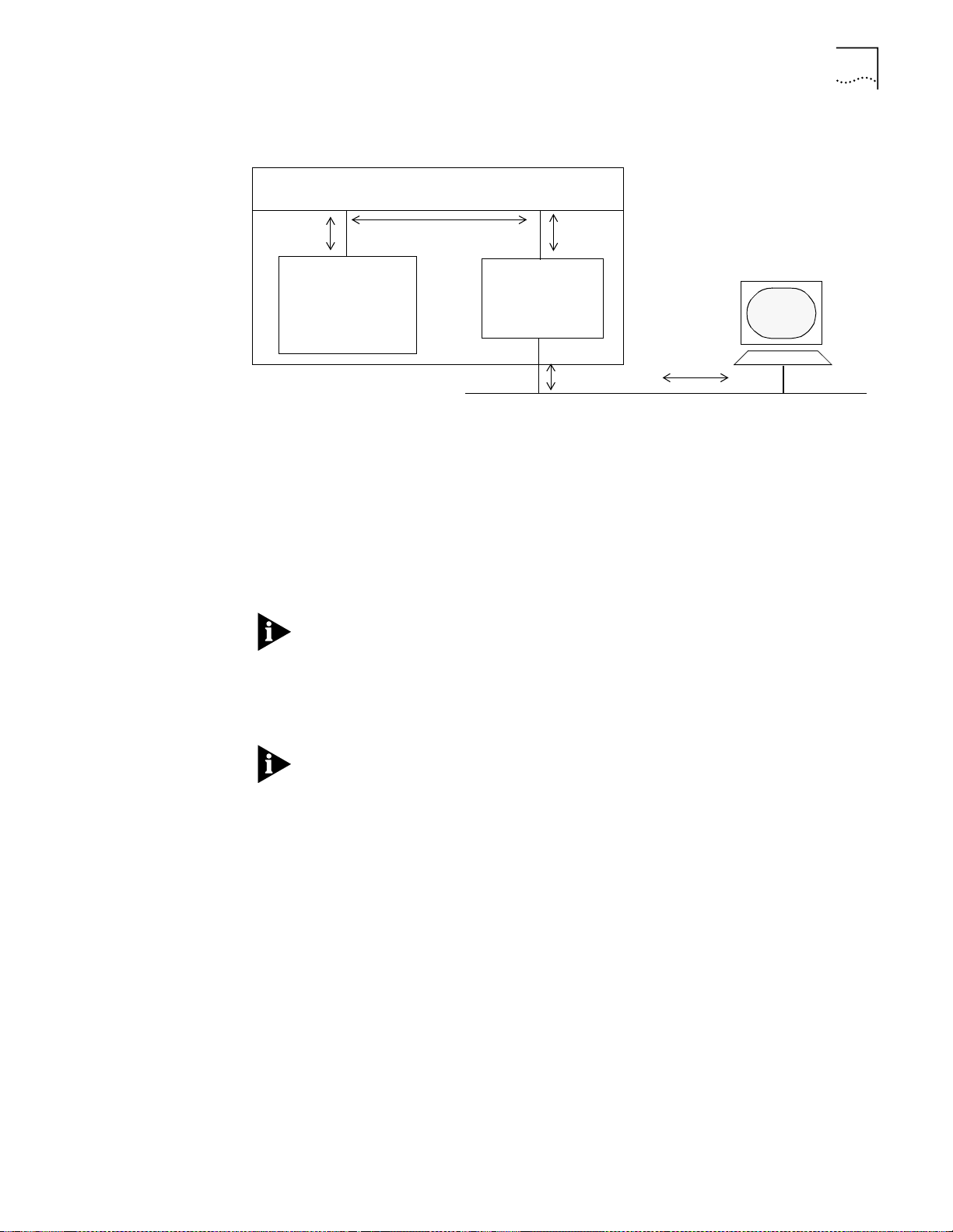
Making In-band Connections
Figure 4-1 shows how the DMM achieves network connectivity.
Management Channel
3. Use an SNMP workstation,
or Telnet, to connect through
the NMC, using the DMM IP
DMM (IP
addresses
reside here)
NMC
address.
4-17
1. Set a subnet sask and
default gateway, then an
IP address, on the DMM
for a backplane network.
Figure 4-1
DMM In-band Connectivity Process
2. Assign th e NM C to the network you
assigned the IP parameters to.
Network
To connect to the DMM in-band (Figure 4-1):
Make sure that you have set up IP connectivity for the single network that you
1
plan to use for IP connectivity, as described in “Setting SNMP Values”earlier in this
chapter.
In networks in which the IP addresses begin with 151, the default subnet mask
may conflict with internally reserved addresses. To avoid this situation, always set a
subnet mask before you set the corresponding IP address.
Use the DMM to assign an IP address to one of its backplane networks, using the
2
SET IP IP_ADDRESS command. You must assign the address from the console port
connection.
Although the DMM supports multiple IP addresses, set only one address (on the
network attached to your default gateway). Assigning multiple IP addresses causes
connectivity and SNMP management problems.
Assign a network monitor card to the network that you have assigned the IP
3
address to, using the SET MODULE NETWORK command.
For example, to set the network for an ENMC:
CB5000> set module 3.2 network ethernet_1
For example, to set the network for interface 1 on an A-ENMC:
CB5000> set module 3.2 module_interface_1 network ethernet_1
Enable the interface using the SET MODULE INTERFACE ENABLE command.
4
For example, to enable the interface for an ENMC:
CB5000> set module 3.2 interface enable
For example, to enable interface 2 on an A-ENMC:
CB5000> set module 3.2 module_interface_2 interface enable
Page 66

4-18
C
HAPTER
4: C
ONFIGURING THE
DMM
Connect the monitoring station to a CoreBuilder 5000 network through a
5
CoreBuilder 5000 media module.
Use Telnet or SNMP to reach the DMM using the IP address that you assigned. In
6
routed networks you can connect to the DMM using only the currently active
default gateway.
If you have followed the procedure, the network monitor card provides a
connection to the DMM across the hub management channel. The DMM
architecture places the following restrictions on Telnet sessions:
■
You cannot assign the network monitor card to an isolated network using
Telnet without losing your connection
■
You cannot change the IP address associated with the network monitor card
that is providing the connection
For information on how SwitchModules communicate management information
to the DMM from the network management station that is attached to a
SwitchModule port, see the section titled “Virtual Bridging Overview” in Chapter
2, “Configuring the SwitchModule” in the
.
Guide
CoreBuilder 5000 SwitchModule User
Setting Up Network Monitoring
Monitoring Multiple
Networks
Simultaneously
This section describes:
■
Monitoring Multiple Networks Simultaneously
■
Setting Up Redundant Network Monitor Cards
■
Enabling DLM Mode on an A-ENMC
The DMM supports multiple network monitor cards.
To monitor multiple networks simultaneously:
Assign a network monitor card to each network that you want to monitor, using
1
the SET MODULE NETWORK command.
Enable the network interface on each card using the SET MODULE INTERFACE
2
ENABLE command.
You do not need to assign IP information for each network that you are
monitoring. In fact, assign IP information only for the network that you are using
for in-band connectivity.
Page 67

Setting Up Network Monitoring
4-19
Setting Up Redundant
Network Monitor Cards
Enabling DLM Mode on
an A-ENMC
DMM supports network monitor card (N+1) redundancy. If you assign a standby
NMC, it assumes the role of any active card in the event of a hardware failure.
To assign a standby NMC:
1
Set the
active
NMCs to networks as described earlier in this section, and enable
the NMC interfaces.
Use the SET MODULE INTERFACE STANDBY command to set the spare NMC to
2
standby mode.
To ensure fault-tolerant IP connectivity, assign a network monitor card to be a
standby interface.
If you are using an A-ENMC, assign one of the two interfaces to standby mode.
However, one interface cannot take over for the other interface on the A-ENMC.
®
DMM Version v4.0 supports CoreBuilder 5000 Manager LANsentry
Dynamically
Loadable Modules (DLMs). You must have CoreBuilder 5000 Manager LANsentry
software and the A-ENMC to take advantage of the DLM feature.
Before you download a DLM to an A-ENMC, you must enable DLM mode on that
A-ENMC. To enable DLM mode on an A-ENMC, use the SET MODULE DLM_MODE
ENABLE command.
For example:
CB5000 > set module 3.2 dlm_mode enable
See the
CoreBuilder 5000 Manager LANsentry Advanced Application User Guide
for more information on using DLMs.
The following commands are useful when using DLMs:
■
Enter the following command to show the DLM-related control table entries
that are stored in the DMM:
CB5000> show dlm control
DLM Control Table:
Index Status Owner
----- ------ ------1 VALID Monitor
Page 68

4-20
C
HAPTER
4: C
ONFIGURING THE
DMM
■
Enter the following command to show the status of requests that are made to
the DMM to load DLMs:
CB5000> show dlm request_load_status
DLM Image Load Table:
Name Status Destination Module
------- -------- ------------------ecam executing 01.01
■
Enter the following command to identify any DLM images that are currently
loaded on the DMM:
CB5000> show dlm loaded_image
Loade d DL M Ta ble:
Name Reason Version Load Source
------------------------------------------------------------ecam application 01.00 PATH:TFTP:ecam:151.104.20.81
Saving Configuration Values
Logging Out
When you make configuration changes using the SET command, they are effective
immediately but are not saved permanently. To save commands permanently, use
the SAVE command. Only saved values are in effect upon reset of the DMM or the
hub.
To save all current hub configuration values previously established by the SET
command for all categories, use the following command:
CB5000> save all
Savin g al l pa rameters
When you have finished using the DMM, you may log out. You must either save or
revert any changes that you made to the system before you can log out
successfully.
To log out:
Save all changes.
1
Log out of the system using the LOGOUT command:
2
CB5000> logout
■
If you have saved all changes before you enter this command, you are logged
out of the system. The following message appears:
Good-Bye
■
If you have made configuration changes and you have not saved those
changes, the following message appears:
WARNING: Save unsaved changes before logout
.
Reenter the LOGOUT command to log out of the system after you have saved
(SAVE ALL) your changes, or reverted (REVERT ALL) to the previous configuration.
Page 69

Adding a Second DMM for Fault Tolerance
4-21
Adding a Second
DMM for Fault
To l e r a n c e
DMM Mastership
Priority
When you add a second DMM to a hub, the second DMM automatically goes into
standby mode, providing fault tolerance for the master DMM. Each time that you
enter the SAVE command from the master DMM, the standby DMM learns the
master module’s configuration automatically.
Always install additional DMMs or A/DMMs into a hub with the power on and
another management module configured as the master.
If the master DMM fails for any reason, the standby DMM contains all of the
information it needs to assume the hub mastership role without loss of service:
■
Community table
■
IP table
■
Ethernet card settings
No additional configuration is necessary.
Use the SET MODULE MASTERSHIP_PRIORITY command to establish the order in
which installed DMMs assume command of the hub when the current hub master
fails or resigns.
A master management module has configuration control, management
responsibilities, and fault detection capabilities for the entire hub. Use this
command to assign a priority level to your management modules.
The management module with the highest priority is elected as a master for that
hub. Set the master DMM to the highest priority level, which is 10. This causes
other management modules in the hub to become standbys. If there is a tie
between priority levels of management modules in the same hub, the election for
a master is arbitrary. DMMs always assume mastership over management
modules.
DMMs are factory-set at priority level 10.
Mastership election completion time depends on a management module's
mastership priority setting. Set a master DMM to 10 and slave DMMs to
mastership priority values of 7, 8, or 9 to facilitate the election process.
When a hub contains both a DMM or DMM-EC and an A/DMM, set the
mastership priority of the A/DMM to a higher value than the DMM or the
DMM-EC. Doing so ensures that the A/DMM is elected master, so that you can
take advantage of MIB performance enhancements.
Page 70

4-22
C
HAPTER
4: C
ONFIGURING THE
DMM
DMM Mastership
Elections
Mastership elections occur automatically when a hub powers on and off, or when
a master DMM fails.
Use the SHOW DEVICE RESET_MASTERSHIP command to determine if the DMM
causes a mastership election when you insert it into a hub. Because the setting is
stored in non-volatile RAM, you can set this option in one hub, and set it to take
effect when you insert the module in a second hub.
CAUTION:
Do not reset mastership while modules are being downloaded by the
DMM.
To force a mastership election in a hub, issue the RESET MASTERSHIP command to
the master DMM.
Page 71

U
SING THE
DMM
FOR
N
ETWORK
5
A
DMINISTRATION
This chapter describes how to use management features provided by an installed
and configured CoreBuilder
chapter contains the following sections:
■
Using Telnet to Manage DMM Remotely
■
Using DMM Telnet to Log In to Remote Devices
■
Setting Up SNMP Access
■
Configuring Networks Using the DMM
■
Configuring Token Ring MAC-Address-to-Port Security
■
Using Ethernet Private Line Card Features
■
Preconfiguring (Staging) New Modules
■
Writing and Scheduling Command Scripts
■
Saving and Reverting Configuration Values
■
Uploading and Downloading DMM Configuration Files
®
5000 Distributed Management Module (DMM). The
■
Determining Hub Configuration Using the SHOW Commands
■
Understanding Alerts
DMM commands and conventions are discussed in the
Distributed Management Module Commands Guide
the DMM command conventions, see the
Management Module Command Reference
your DMM.
See Chapter 4 for instructions about how to initially install and configure the
DMM.
CoreBuilder 5000 Distributed
for the commands to configure
CoreBuilder 5000
. After you are familiar with
Page 72
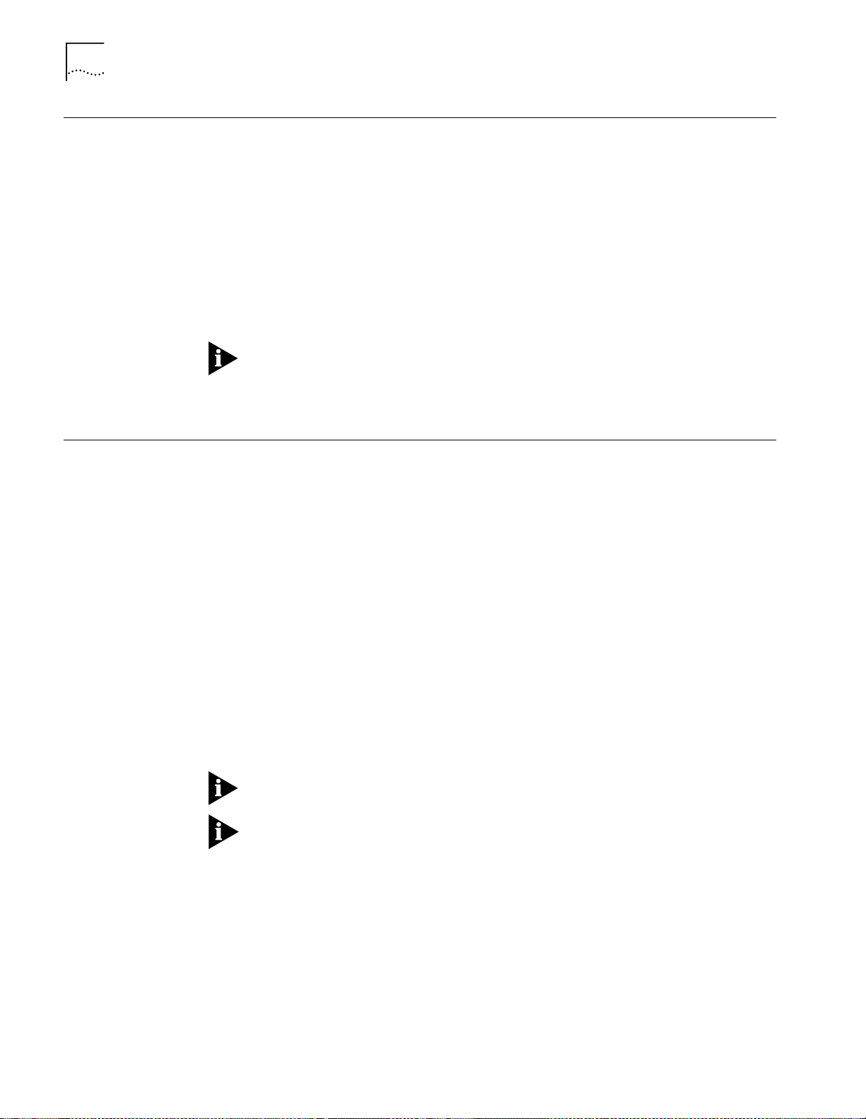
5-2
C
HAPTER
5: U
SING THE
DMM
FOR NETWORK ADMINISTRATION
Using Telnet to Manage DMM Remotely
Using DMM Telnet to Log In to Remote Devices
DMM supports up to four incoming Telnet sessions so that you can:
■
Log in remotely to any DMM on the network
■
Manage the network remotely (from a terminal that is attached to a remote
DMM, or from a workstation with Telnet support)
You can manage a DMM across bridges and routers.
To use Telnet to manage DMM remotely:
Establish DMM connectivity as described in Chapter 4.
1
Telnet to the DMM IP address.
2
You may only connect one DMM to a network at a time. If you have a backup
DMM in the hub (for fault-tolerance), you cannot communicate with the backup
DMM in-band. Also be aware that you must be connected to the interface that is
associated with the Active Default Gateway.
This section describes:
■
Logging In to a Remote Device
■
Logging Out from a Remote Device
Logging In to a Remote
Device
To use the DMM Telnet service to log in to a remote device:
Use the following command to connect to a remote DMM or other remote device.
1
You can only log into devices that support the Telnet protocol.
CB5000> telnet <ip addr ess>
If you are logged into a DMM locally, use the following command:
2
CB5000> telnet <ip addr ess>
After you are connected to the remote DMM or remote device, enter the
3
appropriate password. After the password is accepted, all the commands that you
enter are for the remote DMM or remote device and are identical to those that you
enter under that device’s local login.
You are allowed one outgoing Telnet session per console port (2 total).
If you are already logged in remotely, you cannot issue the DMM TELNET
command to hop (log in) to a second device.
Page 73

Setting Up SNMP Access
5-3
Logging Out from a
Remote Device
Setting Up SNMP
Access
When you no longer require a connection to a remote device:
Enter the LOGOUT command. This command disconnects the remote connection
and reconnects the session with the local DMM.
The local management prompt appears on the local screen and the message
Remote session completed
CB5000> logout
Good-Bye
CAUTION:
If TIMEOUT was set for the remote DMM and the time runs out, the
appears.
system logs you out of the remote DMM and returns you to the local DMM.
Unsaved changes are still in effect, but they are lost if the DMM is reset. To save
these changes, reestablish a connection to the DMM and enter the SAVE
command.
Use the DMM community table to select which devices attached to your networks
can use Simple Network Management Protocol (SNMP) to manage the DMM.
Use the DMM SET COMMUNITY command to add device IP addresses to the
Community Table and to assign specific access levels that apply to all devices in the
Community Table.
For example, to allow an address to receive DMM traps only, use the following
DMM command:
CB5000> set community trap_receivers 151.104.99.16 trap
Where:
■
SET COMMUNITY notifies the DMM that you are creating a community table
entry
■
TRAP_RECEIVERS is the name of the community that you are creating
■
151.104.99.16 is the IP address of the remote device that is associated with
this community
■
TRAP is the access rights designation for the community
To allow a device to manage your hub using SNMP, ensure that the DMM that you
want to manage is connected to a network.
Table 5-1 lists available SNMP manager access levels.
Table 5-1
Level Station at IP Address can
trap Receive traps (alerts) from the DMM
read_write Retrieve and modify information about the DMM
read_trap Retrieve information from the DMM, and receive traps
read_only Retrieve information from the DMM
all Retrieve and modify information, and receive traps
SNMP Access Rights for Community Tables
Page 74

5-4
C
HAPTER
5: U
SING THE
DMM
FOR NETWORK ADMINISTRATION
Configuring Networks Using the DMM
Allocating Backplane
Resources
This section describes the commands to configure ONline™ and CoreBuilder 5000
media modules. It includes these sections:
■
Allocating Backplane Resources
■
Configuring CoreBuilder 5000 Token Ring Networks
■
Configuring Modules
■
Configuring Ports
■
Using Token Ring Port Fan-Out Mode
■
Configuring Trunks
■
Controlling the ATM Switch/Control Module
This section covers the following:
■
Backplane Path Description
■
Backplane Path Example
■
Network Backplane Restrictions
Backplane Path Description
Before you configure multiple protocols in a single CoreBuilder 5000 hub, it is
important to understand how the DMM allocates backplane resources. The
following network types share backplane resources:
■
All ONline system concentrator networks
■
CoreBuilder 5000 Ethernet networks
■
CoreBuilder 5000 Fast Ethernet networks
CoreBuilder 5000 Token Ring networks do not share resources with other
protocols.
Use the SHOW BACKPLANE PATHS command to view available network paths and
determine which paths are allocated to each protocol.
Different protocols require differing numbers of backplane paths to create a
network. As you allocate networks of a particular type, paths are consumed and
networks of other types become unavailable.
Page 75

Configuring Networks Using the DMM
Ethernet 1
Ethernet 6
Ethernet 3
Ethernet 5
Ethernet 2
Ethernet 4
TR 13
TR 1
TR 2
FDDI 1
FDDI 2
FDDI 3
FDDI 6
FDDI 7
FDDI 8
FDDI 4
FDDI 5
TR 3
TR 4
TR 5
TR 7
TR 8
TR 10
TR 14
TR 15
TR 9
TR 12
Ethernet 8
Ethernet 7
TR 6
TR 11
5-5
Backplane Path Example
Figure 5-1 diagrams the interrelationship of the three hub protocols in terms of
backplane resource use. The example shows how to use backplane resources in
your network.
Example
Figure 5-1
Backplane Path Use
For example, if Ethernet 1 is in use, any networks that overlap Ethernet 1
(networks that share the same backplane resources) are unavailable. As the
diagram shows, using Ethernet 1 makes ONline TR paths 1 through 6 and FDDI
paths 1 through 3 unavailable.
As an additional example, if ONline Token Ring path 15 is in use, any networks
that overlap ONline Token Ring 15 (meaning that they share the same backplane
resources) are unavailable. As the diagram shows, using ONline Token Ring 15
makes Ethernet 3 and FDDI 7 and 8 unavailable.
Page 76

5-6
C
HAPTER
5: U
SING THE
DMM
FOR NETWORK ADMINISTRATION
Network Backplane Restrictions
The CoreBuilder 5000 hub has capacity for four Fast Ethernet channels
(FastChannels). When you use assign a FastModule backplane port to a
CoreBuilder 5000 FastChannel, one or more backplane channels become
unavailable for use. Table 5-2 lists the backplane channels that become
unavailable for each Fast Ethernet channel assignment.
Table 5-2
Fast Ethernet Channel Assignment Effect on Backplane Channel
Configuring
CoreBuilder 5000 Token
Ring Networks
Assigning a
Backplane Port to
FastChannel
1 2 7, 8, and 9 4 and 5
2 1 and 2 5, 6, 10, and 11 3 and 6
3 1 1, 2, 3, and 4 1 and 2
4 3 13, 14, 15 7 and 8
Disables
Ethernet
Channel
Disables Token
Ring Channel
Disables FDDI
Channel
CoreBuilder 5000 Token Ring networks allow you to set several features at the
network level, including:
■
Beacon recovery
■
Network mode (backplane or isolated)
■
Ring speed
■
Mismatch resolution
Enabling Beacon Recovery
To enable or disable the beacon recovery mechanism on a CoreBuilder 5000 Token
Ring network, use the SET NETWORK TOKEN_RING BCN_RECOVERY command.
When enabled, the beacon recovery feature removes beaconing stations from the
rings at the module level.
To enable the beacon recovery mechanism on backplane network token_ring_3,
use the following command:
CB5000> set network token_ring token_ring_3 bcn_recovery enable
Value set to ENABLED.
DMM allows you to set a beacon recovery threshold for each module.
Setting Network Mode (Backplane or Isolated)
To toggle entire rings between isolated (module-level) and backplane (hub-wide)
Token Ring networks, use the SET NETWORK TOKEN_RING ISOLATED command.
This command is valid to port-switched modules only.
To assign all ports assigned to isolated_3 (module-level ring) in module 7 to
token_ring_3 (backplane ring), use the following command:
CB5000> set network token_ring isolated_3 7 mode backplane
Network mode set to BACKPLANE.
Page 77

Configuring Networks Using the DMM
5-7
You can implement each of the 10 available Token Rings on CoreBuilder 5000
port-switching media modules either on a backplane (hub-wide) or an isolated
(module-level) network. Use this command to toggle sets of ports between
backplane and isolated. You may only toggle rings 1 through 10. If you entered
the command from the previous example, all ports that are assigned to network
isolated_3 join backplane network token_ring_3 (Figure 5-2).
Figure 5-2
CoreBuilder 5000 Token Ring Network Mode
You specify a slot number when you indicate the isolated network that the
command affects. The command only affects the specified slot and cannot be
used to isolate every module in the hub.
Selecting a Network Ring Speed
To set the ring speed for any CoreBuilder 5000 Token Ring backplane (hub-wide)
or isolated (module-level) network, use the SET NETWORK TOKEN_RING
RING_SPEED command.
To set the ring speed for backplane network TOKEN_RING_4 To 16 Mbps, use the
following command:
CB5000> set ne tw or k token_r in g to ke n_ring_4 ring_speed 16mb ps
Value set to 16 MBPS.
Page 78

5-8
C
HAPTER
5: U
SING THE
DMM
FOR NETWORK ADMINISTRATION
To set the ring speed of a specified network, use the
SET NETWORK TOKEN_RING RING_SPEED command. The system automatically
sets any module, port, trunk, or daughter card that is assigned to the network to
the speed of the network.
Enabling Mismatch Resolution
To perform address-to-port mapping when you use fan-out devices on per-module
switching modules, use the
SET NETWORK TOKEN_RING MISMATCH_RESOLUTION command. This command
enables or disables the mismatch resolution algorithm for the specified network.
This command applies to per-module switching modules only.
To enable the mismatch resolution mechanism on backplane network
token_ring_3, use the following command:
CB5000> set network token_ring token_ring_3 mismatch_resolution
enable
Value set to ENABLED.
Configuring Modules
This section describes how to:
■
Configure modules
■
Assign module networks
Configure Modules
To configure CoreBuilder 5000 and ONline media modules in the hub, use the SET
MODULE command. Because there may be more than one device in a slot (a
CoreBuilder 5000 media module with a network monitor card, for example), you
specify modules using <slot.subslot> notation.
Assign Module Networks
Modules that are assigned to the same network form a ring (network) or Ethernet
segment. Modules that are assigned to different networks cannot communicate
with each other unless the networks are bridged. You may assign all
CoreBuilder 5000 modules to backplane networks.
If you isolate a module, the isolated module cannot send or receive any traffic
from other modules in the hub. Initially, all modules are factory-set to network 1,
but initialize as isolated if a management module is installed in the hub.
To assign the Ethernet media module in slot 7 of a hub to Ethernet network 3, use
the following command:
CB5000> set module 7.1 network e thernet_3
Page 79

Configuring Networks Using the DMM
5-9
Configuring Ports
This section describes SET commands to manage the ports of modules in your
network.
Setting Port Mode
To enable (activate) port 2 in slot 5, use the SET PORT command as shown:
CB5000> set port 2.5 mode enable
Setting Up Port Redundancy
The CoreBuilder 5000 hub provides fault-tolerance by allowing you to establish
redundant ports. After you have set up redundant ports, the DMM automatically
switches to the backup port if the primary port loses its connection.
To establish or remove redundancy between two ports, use the
SET PORT MODE REDUNDANT or NON_REDUNDANT command. For example, to
establish port 1 in slot 6 as the primary port and port 3 in slot 6 as the backup:
CB5000> set port 6.1 mode redundant 6.3
Port 06.01 set to REDUNDANT PRIMARY.Port 06.03 set to REDUNDANT
BACKUP.
After a failure, if the primary port functions properly again, the DMM
automatically switches the connection back to that port.
Using Port Groups
The DMM allows you to assign ports to groups. You can use these groups to
enable, disable, or change the network assignment of a group of ports.
To assign a port to a port group, use the following command:
CB5000> se t gr ou p <g roup_id > po rt <slo t.port>
You can use the SHOW GROUP ALL command for a list of available group IDs.
To enable a group of ports, use the following command:
CB5000> set gr ou p <g roup_id> mode enable
To assign a group of ports to a network, use the following command:
CB5000> se t gr ou p <g roup_id > ne tw or k <network>
Ensure that all ports in a group are the same type (for example, Ethernet). Do not
use the SET GROUP NETWORK command on a connector-switched module.
Page 80

5-10
C
HAPTER
5: U
SING THE
DMM
FOR NETWORK ADMINISTRATION
Using Token Ring Port
Fan-Out Mode
Use the SET PORT FAN_OUT_MODE command to make a CoreBuilder 5000 Token
Ring port compatible with fan-out devices such as the IBM 8228. The fan-out
function allows multiple stations to attach to a single port.
This feature requires Token Ring media module code Version v1.2 or later.
This feature is required because not all fan-out devices assert phantom (phantom
indicates the presence of a station). When fan-out mode is:
■
Disabled
(the default) — CoreBuilder 5000 Token Ring ports automatically
wrap and unwrap based on the detection of phantom. In this mode, a fan-out
device requires an adapter to assert phantom before that device can insert into
the ring.
■
Enabled
— The port unwraps regardless of the presence of phantom.
Enabling fan-out mode with no station or fan-out device attached breaks the ring
and causes beaconing. Avoid this situation because beacon recovery causes a brief
disruption to all users on the ring.
Because phantom is ignored when fan-out mode is enabled, the only way to clear
a BEACON_WRAP or WRONG_SPEED condition when a port is in fan-out mode is
to disable, then reenable the port. Ring speed detection does not operate when a
port is in fan-out mode. Beacon recovery wraps fan-out devices that contain
incorrect speed stations.
Configuring Trunks
When you disable a port, the fan-out mode is automatically disabled. As a result,
you explicitly enable fan-out mode when you reenable the port. The need to
explicitly enable fan-out mode as a separate step helps prevent you from enabling
fan-out mode with no device attached.
To enable fan-out mode, use the following command:
CB5000> set port 6.2 fan_ out_mode enable
Port 06.02 set to ENABLED.
To configure the following options for either copper or fiber trunk ports, use the
SET TRUNK command to:
■
Enable or disable a trunk
■
Select a trunk network
■
Set the trunk compatibility mode
Enabling and Disabling Trunks
To enable or disable CoreBuilder 5000 Token Ring trunk ports, use the SET TRUNK
MODE command. The syntax is as follows:
set trunk <slot> <ring_in or ring_out>.<1 or 2> mode <enable or
disable>
Page 81

Configuring Networks Using the DMM
5-11
Selecting a Trunk Network
To set a trunk port to a particular backplane or isolated network, use the SET
TRUNK NETWORK command. The syntax is as follows:
set trunk <
slot> <ring_in or ring_out>
.<1 or 2> network
<token_ring_1..._10 or isolated_1..._10>
Setting Trunk Compatibility Mode
To ensure that signalling used by a CoreBuilder 5000 trunk port is compatible with
the trunk port connected at the other end of the copper or fiber cable, use the SET
TRUNK COMPATIBILITY_MODE command.
Table 5-3 shows the compatibility settings when connecting an ONline module
trunk port.
Table 5-3
To Connect ONline Module to Set Compatibility Mode to
ONline
CoreBuilder®5000 Disable
IBM 8230 CAU (Controlled Access Unit) Enable
ONline Module Compatibility Settings
™
Disable
Table 5-4 shows the compatibility settings to use when connecting a
CoreBuilder 5000 module trunk port.
Table 5-4
To Connect CoreBuilder 5000 Module to Set Compatibility Mode to
ONline™ System Concentrator ONline
CoreBuilder®5000 hub or ONline 5204M-CR CoreBuilder 5000
ONsemble® Token Ring hub ONsemble
IBM 8238 Nways Token Ring Stackable Hub 8238
IBM 8230 CAU 8230
IBM 8250 Multiprotocol Intelligent Hub 8250
IBM 8260 Multiprotocol Intelligent Switching Hub 8260
IBM 8228 MAU 8230
CoreBuilder 5000 Compatibility Settings
Use the SET TRUNK COMPATIBILITY_MODE command as follows:
CB5000> set trunk <slot> <ring_in or ring_out>.<1 or 2>
compatibility_mode <mode>
Where:
<slot> = slot containing the trunk port
<mode> = DISABLE, ENABLE, CoreBuilder 5000, ONline, ONsemble, 8230, 8238,
8250, 8260
Page 82

5-12
C
HAPTER
5: U
SING THE
DMM
FOR NETWORK ADMINISTRATION
Controlling the ATM
Switch/Control Module
The 3Com ATM Switch/Control module has agent software that controls
Asynchronous Transfer Mode (ATM) modules in a hub. Therefore, the DMM does
not control most of the major ATM module functions. The DMM does, however,
have limited control over the module for reporting purposes.
DMM provides the following configuration and status functions for the ATM
Switch/Control:
■
Configuring the Module IP Default Gateway
■
Configuring the Module ATM Port
■
Setting the Port IP Address
■
Setting the Port IP Subnet Mask
Configuring the Module IP Default Gateway
The IP Default Gateway is the gateway that the module uses when responding to
IP requests.
To set the default gateway on the module, use the following command:
CB5000> set module <slot>.1 default_gateway
Configuring the Module ATM Port
The module has no physical port, but instead has a logical ATM port that allows
network access to the module’s ATM control agent. You can configure the
following settings for the port:
■
Port IP Address
■
Port IP Subnet Mask
The DMM cannot enable or disable the ATM port.
Setting the Port IP Address
To set the ATM port IP address, use the following command:
CB5000> set port <slot>.1 ip_a ddr es s <ip address>
Setting the Port IP Subnet Mask
To set the ATM port subnet mask, use the following command:
CB5000> set port <slot>.1 subn et_ ma sk <mask>
Page 83

Configuring Token Ring MAC-Address-to-Port Security
5-13
Configuring Token
Ring
MAC-Address-to-Port
Security
MAC-Address-to-Port
Security Overview
This section contains information on the following topics:
■
MAC-Address-to-Port Security Overview
■
Implementing MAC-Address-to-Port Security
■
Using the Autolearning Feature
DMM MAC-address-to-port security allows you to secure your network by
comparing station adapter card MAC addresses against a table that you create.
The DMM monitors traffic on each port and performs the action that you specify
when it detects a station whose MAC address is not included in the table. This
process applies to CoreBuilder 5000 Token Ring modules only.
Upon detecting an invalid MAC address, the DMM performs one of the following:
■
Disables the port
■
Sends a trap
■
Disables the port and sends a trap
■
Takes no action
You can assign up to seven MAC addresses to each port in your network. Because
you can enter multiple MAC addresses for each port, the security feature supports
fan-out devices.
Implementing
MAC-Address-to-Port
Security
If an intrusion causes the DMM to disable a port, you must issue the SET PORT
MODE ENABLE command to reenable the port.
To implement MAC-address-to-port security on a port:
Use the following command to assign a MAC address to the selected port:
1
CB5000> set security port <slot.port> mac_addres s <mac ad dr es s>
Use the following command to enable the security feature for the port:
2
CB5000> set security port <slot.port> mode enable
If you use the ALL option instead of specifying a slot and port, the DMM applies
the command to all modules in the hub that support security.
Use the following command to specify the action for the DMM to take when an
3
intrusion occurs:
CB5000> set security port <slot.port> action_o n_ in tr usion <action>
Page 84

5-14
C
HAPTER
5: U
SING THE
DMM
FOR NETWORK ADMINISTRATION
Use the SHOW SECURITY PORT command to display the MAC address and
4
security setting for a specific module and port, for all ports, or for all ports of a
specific module.
The following example displays security settings for all ports on the fiber module in
slot 7.
CB5000> show security port 7.all
Security Display for Module:
Port Mode MAC Address General Information
07.01 ENABLED 08.00.8f.1b.0b.ad TOKEN_RING_1
07.02 ENABLED 08.00.8f.3c.c6.1e TOKEN_RING_1
07.03 ENABLED 08.00.8f.00-0e-c6 TOKEN_RING_1
07.04 ENABLED 08.00.8f.00-0e-2e TOKEN_RING_1
Using the Autolearning
Feature
This section describes:
■
Autolearning Feature Overview
■
Implementing the Autolearning Feature
■
Configuring the Autolearning Mask
■
Downloading the Autolearning Database
■
Showing Learned Addresses
■
Clearing the MAC Address Table
■
Clearing the Autolearning Database
■
Defining a MAC Address Manually
Autolearning Feature Overview
Autolearning is a feature that allows the DMM to:
■
Automatically learn the MAC addresses of stations that are attached to Token
Ring ports
■
Add these addresses to the table of valid MAC addresses
These MAC addresses are stored in two databases on the DMM:
■
The Autolearning database
■
The port MAC address database
When the Autolearning capture process begins, the DMM stores the MAC
addresses of packets that have passed through the specified ports in the
Autolearning database. You download the contents of the Autolearning database
to the port MAC address database, also on the DMM.
Page 85

Configuring Token Ring MAC-Address-to-Port Security
Implementing the Autolearning Feature
To allow the DMM to automatically learn the MAC addresses for all connected
ports on the network:
Use the following command to disable Security Mode while the DMM learns the
1
MAC addresses:
CB5000 > set security port <slot.port> mode disable
Disable the Autolearning Mask:
2
CB5000> set security autolearn <slot.port> mask disable
The DMM can now learn MAC addresses from ports.
Enable the ports to allow traffic to pass through the network so that the DMM can
3
learn which MAC addresses are associated with which ports.
CB5000 > set po rt <slot.port > mode enable
Initiate Autolearning to enable the DMM to automatically learn the valid MAC
4
addresses associated with Token Ring ports.
CB5000> set security autolearn <slot.port> capture
Download the learned MAC addresses from the Autolearning database to the port
5
MAC address database.
CB5000 > set security autolearn <slot.port> download
5-15
Save the security configuration values.
6
CB5000> save security
Configuring the Autolearning Mask
The Autolearning Mask:
■
Allows or prevents a the DMM from learning a port's MAC addresses during
Autolearning
■
Determines if the DMM is allowed or prevented from downloading learned
MAC addresses to the ports
The AUTOLEARN MASK command either allows (disables the mask) or prevents
(enables the mask) the DMM from learning or downloading MAC addresses for
ports.
Enter the following command to allow the DMM to learn MAC addresses during
Autolearning for all ports on the module in slot 3:
CB5000> set security autolearn 3.all mask disable
Downloading the Autolearning Database
You must download the contents of the Autolearning database to the port MAC
address database on the DMM for the MAC Addresses to be associated with the
ports. When Autolearning Capture is complete, download the Autolearning
database to initiate port security. Depending on the amount of network traffic
transmitted to the ports, you may elect to defer the Autolearn download for a day,
several days, or a week. By waiting to download the captured MAC addresses, you
allow all of a port's associated MAC addresses to be entered into the Autolearning
database.
Page 86

5-16
C
HAPTER
5: U
SING THE
DMM
FOR NETWORK ADMINISTRATION
The Autolearning database for a DMM can contain a maximum of 360 MAC
addresses.
Because a maximum of seven MAC addresses can be associated with one port,
only seven MAC addresses are downloaded. The seven MAC addresses with the
lowest alphanumerical values are downloaded from the Autolearning database to
the port MAC address database on the DMM.
Enter the following command to download the MAC address information for the
Token Ring module in slot 3 port 1:
CB5000> set security autolearn 3.1 download
This command downloads the information from the Autolearning database to the
port MAC address database.
If MAC addresses for the specified port currently exist in the port MAC address
database, the following message appears when you issue the AUTOLEARN
DOWNLOAD command:
Note: Overwriting exist ing addresses in the Securit y database.
The following message appears upon completion of the AUTOLEARN
DOWNLOAD command (where y indicates the total number of addresses that
were copied to the port's MAC address table):
Autolearn download done ; downloaded y addresses tot al.
If a port has more than seven MAC addresses in the Autolearning database at the
time of the download, the following message appears upon completion of the
AUTOLEARN DOWNLOAD command:
Note: at least one autolearned address was skipped because the port
with which it is associated has more than seven autolearned
addresses.
If any MAC address was skipped because the concentrator limit was reached, the
following message appears upon completion of the AUTOLEARN DOWNLOAD
command:
Note: the number of autolearned addresses exceeds the concentrator
limit. Only the first X addresses (as ordered by slot, port, and
addr) were downloaded.
Where X indicates 360 MAC addresses for a DMM.
Showing Learned Addresses
The SHOW SECURITY AUTOLEARN command displays all of the MAC addresses
that have been learned and stored in the Autolearning database. Only entries for
ports specified in the command are displayed. An additional message is provided if
any port has more than seven entries, or if the concentrator limit has been
exceeded.
To display all associated MAC addresses for the ports on the module in slot 17,
enter the following command.
CB5000> show security autolearn 17.all
Page 87

Configuring Token Ring MAC-Address-to-Port Security
5-17
Clearing the MAC Address Table
You may want to manually clear a MAC address for a port instead of initiating
Autolearning to recapture a port's associated MAC addresses. For example, after
Autolearning Capture has completed and the information downloaded, a station
may be removed from the network.
Enter the following command to clear the MAC address 08-54-6f-01-32-08 from
the port MAC address database for the CoreBuilder 5000 Token Ring module in
slot 3, port 1.
CB5000> clear security port 3.1 mac_address 08-54-6f-01-32-08
Use the ALL option to remove all associated MAC addresses for a specific port, all
ports on a module, or all ports on all modules in a concentrator. If you do not
enter a MAC address, the command defaults to ALL, which clears all MAC
addresses for the specified ports.
Clearing the Autolearning Database
When you issue a CLEAR SECURITY AUTOLEARN command, the MAC address
that you specify (or all MAC addresses) is cleared from the Autolearn Address
table.
To remove all old MAC addresses from the Autolearning database, clear the
Autolearn Address table using the CLEAR SECURITY AUTOLEARN <slot>.all
MAC_ADDRESS command and then clear the Security Address database using the
CLEAR SECURITY PORT <slot>.all MAC_ADDRESS command.
Enter the following command to clear all MAC addresses that are associated with
the CoreBuilder 5000 Token Ring module in slot 3, port 1, from the Autolearning
database on the DMM:
CB5000> clear security autolearn 3.1 mac_address all
If you do not enter a MAC address, the command defaults to ALL, which clears all
MAC addresses from the Autolearning database for the specified ports.
Defining a MAC Address Manually
The DMM provides you with the flexibility of manually adding MAC addresses into
a port's MAC address database, and into the Autolearning database. You may use
this feature to add one or more MAC addresses to a port MAC address database
instead of Autolearning a port's associated MAC addresses.
For example, after Autolearning Capture has completed and the MAC addresses
are downloaded, a new station may be added to the network. You can add the
new station's MAC address to a port's MAC address database using the SET
SECURITY PORT MAC_ADDRESS command.
Enter the following command to add the MAC address 08-54-6f-01-32-08 to the
MAC address database for the CoreBuilder 5000 Token Ring module in slot 3,
port 1:
CB5000> set security port 3.1 mac_address 08-54-6f-01-32-08
Note that the MAC addresses 00-00-00-00-00-00 and FF-FF-FF-FF-FF-FF are
invalid.
Page 88

5-18
C
HAPTER
5: U
SING THE
DMM
FOR NETWORK ADMINISTRATION
Use the following command to add the MAC address 08-54-6f-01-32-08 into the
Autolearning database for the CoreBuilder 5000 Token Ring module in slot 3, port
1. This command specifies that port 1 in slot 3 is associated with the MAC address
08-54-6f-01-32-08.
CB5000 > set security autolearn 3.1 mac_address 08-54-6f-01-32-08
Using Ethernet Private Line Card Features
The Ethernet Private Line Card provides secure Ethernet networks by:
■
Eavesdropping Protection
— Prevents users from seeing the contents of
packets that are destined for other users.
■
Intrusion Protection
Detecting and reporting intruder transmissions on the network
■
Preventing intruder transmissions to other ports by jamming the packet
■
Automatically disabling ports that are the source of intruder transmissions
■
■
Autolearning
— Enforces security by:
— Automatically learns MAC address to port assignments and
stores these entries in the Security Address Table. Eavesdrop and intrusion
protection features look up MAC addresses in the table to enforce security.
By providing both eavesdropping protection and intruder detection you:
■
Prevent unwanted listeners from monitoring the transmission of Ethernet
packets
■
Stop intruders from transmitting packets on the network
The 3Com
Ethernet Private Line Card User Guide
describes a wide variety of
Ethernet security commands.
The addition of MAC-address-to-port security to DMM caused conflicts with the
command syntax used for managing the Ethernet Private Line Card (PLC). To
eliminate these conflicts, the command noun syntax in DMM was changed from
SECURITY to SECURITY_ADVANCED for all PLC functions. The SET SECURITY
commands provide port-to-MAC address security and the SET
SECURITY_ADVANCED commands provide access to the security parameters of
CoreBuilder 5000 Ethernet Private Line Card security.
For example, the SET SECURITY PORT JAMMING command is now the SET
SECURITY_ADVANCED PORT JAMMING command.
Page 89

Preconfiguring (Staging) New Modules
5-19
Preconfiguring
(Staging) New
Modules
Staging Overview
Understanding Staging
This section contains:
■
Staging Overview
■
Understanding Staging
The staging feature is available on CoreBuilder 5000 modules only.
With staging, you can configure a module in a hub that is not attached to an
active network, and then transport the module to the hub in which the module
will operate. When you plug the module into the new hub, the module configures
itself to the configuration held in its non-volatile storage.
To stage a module:
Set the module DIP switch to configure from NVRAM.
1
Configure the module in a hub with a DMM.
2
Remove the module, and install it in another hub.
3
For staging to work correctly, disable the ability of modules to boot using their
own DIP switch values (use the SET DEVICE DIP_CONFIGURATION DISABLE
command). This setting (DISABLED) is the factory default.
The manner in which the module is configured in the new hub depends on the
sequence of events that are used in the staging process. The scenarios in the
following sections assume that you have already set the appropriate DIP switch on
the module that you are staging to configure the module from NVRAM (rather
than from the DIP switches).
The two staging scenarios are:
■
Staging in a DMM-managed hub
■
Staging in an unmanaged hub
Staging in a DMM-Managed Hub
When it is installed in a DMM-managed hub, the DMM searches its
own
database
for configuration information for that slot.
■
If the configuration information exists and is for the same type of module that
was just installed, the DMM
teaches
the module the configuration it has for
the slot.
■
If the DMM does not have any configuration information for the slot, or it has
stored information for another module type that was in that slot previously, it
assesses the module-supplied configuration information.
■
When the DMM ensures that the module-supplied configuration will not
adversely affect any current module configurations, it
configuration. That is, the DMM accepts the
■
If there are conflicts between the DMM configuration information and the
staged
learns
the new module’s
configuration information.
staged module, the DMM isolates the offending port and uses default
configuration values for that module.
Page 90

5-20
C
HAPTER
5: U
SING THE
DMM
FOR NETWORK ADMINISTRATION
Staging in an Unmanaged Hub
When it is installed in an unmanaged hub, a module that is “staged” by a DMM in
another hub is configured to the contents of its non-volatile storage.
To stage a module or modules to use port redundancy, configure and install the
module or modules in the same slots in the staging hub as will be installed in the
working hub. If you do not, DMM ignores the redundancy settings.
Writing and Scheduling Command Scripts
Writing Command
Scripts
This section describes:
■
Writing Command Scripts
■
Downloading ASCII Script Files
■
Scheduling Command Scripts
Because of these features, you can automate redundant DMM functions.
With scripting you can create a command file that executes a list of management
commands. Scripts may be executed:
■
Using the RUN SCRIPT command
■
In response to a threshold event
■
At a predetermined time, using the scheduling feature described in this chapter
This section describes:
■
Required Login Privileges
■
Available DMM Commands
■
Maximum Number of Scripts
■
Maximum Script Length
■
Placing Comments in Scripts
■
Calling Other Scripts
■
Using Script Recursion
■
Using the SET ALERT SCRIPT Command
■
Using the RUN SCRIPT Command
■
Using the SHOW SCRIPT Command
Required Login Privileges
You must be logged in as a super user or administrator to execute scripts.
Page 91

Writing and Scheduling Command Scripts
5-21
Available DMM Commands
All DMM commands can be executed from a script file except:
■
DOWNLOAD
■
MAINTAIN
■
MONITOR
■
PING
■
TELNET
■
UPLOAD IN_BAND DEVICE CONFIGURATION
Maximum Number of Scripts
Each DMM allows a maximum of eight scripts. The DMM verifies the syntax of a
script file when the script is executed. Misspelled entries or invalid commands
abort script execution.
Maximum Script Length
A single script file can have a maximum of 15 lines with 72 characters per line.
Placing Comments in Scripts
Comment fields are allowed in the command lines. Comments may start
anywhere on the command line but must be preceded by a pound sign (#). All text
that follows the pound sign until the end of the line is ignored. Comments that
span more than one line are counted as part of the 15-line maximum.
Calling Other Scripts
Scripts can invoke other scripts. The DMM supports a maximum of four levels of
embedded scripting. After an embedded script has completed execution, it returns
control to the script that invoked it. If the maximum embedded call level is
reached, that command line is ignored and script execution continues to the next
command line.
Using Script Recursion
A script cannot call itself (that is, recursion is not allowed). If a script calls itself, the
command line is ignored and script executes the next command line.
Using the SET ALERT SCRIPT Command
Use the SET ALERT SCRIPT command to enable or disable trap generation when a
script executes. If enabled, traps are generated for both of these conditions
(nested abort and recursive abort). A trap contains the script number, script name,
how the script was executed (RUN command or defined threshold), and the script
execution status (OK, Abort, Nested Abort, Recursive Abort).
Page 92

5-22
C
HAPTER
5: U
SING THE
DMM
FOR NETWORK ADMINISTRATION
Using the RUN SCRIPT Command
Script output from the RUN SCRIPT command is displayed at the originating
terminal or workstation.
The following command examples show how to create and name a script. This
example script contains two SET commands, is defined as script 1, and identified
as ENG3:
CB5000> set script 1 insert 1
Enter line(s) to insert.
Enter a blank line to quit this mode.
>
CB5000> set port 12.2 mode enable
CB5000> set port 17.1 mod e enable
CB5000> set script 1 name ENG3
Script 1 NAME CHANGED TO ENG3
Using the SHOW SCRIPT Command
Use the SHOW SCRIPT VERBOSE command as shown to display the contents of
the script file:
CB5000> show scrip t 1 ve rb ose
Script Number:1 Script Name: ENG3
1 set port 12.2 mode enable
2 set port 17.1 mode enable
Downloading ASCII
Script Files
You can download ASCII files that contain DMM command scripts. The definition
of the script file is the same one described for files created at the command line.
Script File Header
The first line of a downloadable script file contains a header, as follows:
<File Type> <File Name> <File Number>
Table 5-5 describes each of the fields in the header.
Table 5-5
Field Name Purpose
File Type Defines the type of file. Mandatory SCRIPT
File Name Assigns a name to the script
File Number Indicates specific script number
■
If the File Name is missing, the system does not assign a name.
■
If the File Number is missing, the DMM attempts to download the file into the
Script File Header Fields
file.
to download to.
Mandatory or
Optional?
Optional Any characters valid
Optional 1 through 8
Valid Values
for a UNIX filename
first available script in its database. If no scripts are available, the download fails
and the DMM displays a message. If a File Number is specified, the DMM writes
the file to that script slot, overwriting the previous contents.
Page 93

Writing and Scheduling Command Scripts
The following is a sample script header:
SCRIPT ethernet_script 2
Downloading the Script File
To download a script file using the terminal interface:
Using the SHOW TFTP command, make sure that the DMM has been assigned the
1
correct IP address and TFTP filename.
Enter the following command:
2
CB5000> download in_band device ascii
If the download is successful, the file is stored in the scripts database and the
following message appears:
Download file stored as SCRIPT file number n
Where n is a number from 1 through 8 for the script where the file was stored.
5-23
Scheduling Command
Scripts
With scheduling, you can execute scripts at a specific time of day, week, or month.
You can define a maximum of 20 schedules for each DMM. To automatically run a
script, each schedule must include the following information:
■
Schedule identification number
■
Time of day that a script is to run
■
Identification number of the script
■
Day or group of days that a script is to run
Scheduling also enables you to define three different schedule groups: Weekday,
Weekend, and Holiday, which contain days or dates. These days or dates may
identify a typical work week, weekend, and holiday schedule for the organizations
in your company.
This section describes:
■
Including Port Groups in Schedules
■
Scheduling Examples
Including Port Groups in Schedules
After you define a port group, you can include the group in a schedule's
configuration. A schedule then executes a script on the days or dates that are
specified in a group. Schedule groups save you time because you can associate a
group with a schedule, rather than inputting each day or date into a new or
existing schedule.
Page 94

5-24
C
HAPTER
5: U
SING THE
DMM
FOR NETWORK ADMINISTRATION
Scheduling Examples
The following scheduling command examples describe how to set up three
schedules, which enable and disable user ports at specific times, days, and dates.
Schedule 1 does the following:
■
Executes script 1 (which enables all user ports)
■
Executes script 1 every day (except Sunday) at 6:00 a.m. (which associates the
user-defined Weekday group with schedule 1)
Schedule 2 does the following:
■
Executes script 3 (which disables all user ports)
■
Executes script 3 every weekday at 6:00 p.m. (which associates the
user-defined Weekday group with schedule 2)
Schedule 3 does the following:
■
Executes script 3 (which disables all user ports)
■
Executes script 3 on all dates specified in the Holiday group at 12:00 noon
To create schedules 1, 2, and 3:
Define schedules 1, 2, and 3 by specifying the schedule number, the time a script
1
is to execute, and the script number that is to execute.
CB5000> set schedule 1 time 06:00 script 1
CB5000> set schedule 2 time 18:00 script 3
CB5000> set schedule 3 time 12:00 script 3
Set up a Weekday schedule group.
2
Use the following commands to define a Weekday group consisting of Monday
through Friday.
CB5000> set schedule weekday include_day monday
CB5000> set schedule weekday include_day tuesday
CB5000> set schedule weekday include_day wednesday
CB5000> set schedule weekday include_day thursday
CB5000> set schedule weekday include_day friday
Set up a Holiday schedule group. A holiday group can contain a maximum of 10
3
entries.
CB5000> set schedule holiday include_date 12/25
CB5000> set schedule holiday include_date 12/26
CB5000> set schedule holiday include_date 1/1
Associate schedules 1, 2, and 3 with their schedule groups.
4
CB5000> set schedule 1 include_day weekday
CB5000> set schedule 2 include_day weekday
CB5000> set schedule 3 include_date holiday
Page 95

Saving and Reverting Configuration Values
Enable all schedules.
5
CB5000> set schedule all mode enable
Use the SHOW SCHEDULE command to display all schedule configurations.
6
CB5000> show schedule all
Schedule Script Days
Index Mode Time Number MTWTFSS Dates
------ -------- ------------------------------1 ENABLED 6:00 1 ++++++
2 ENABLED 18:00 3 ++++++
3 ENABLED 12:00 3 +HOLIDAY
5-25
Saving and Reverting
Configuration Values
Saving Configuration
Val ues
This section describes the following:
■
Saving Configuration Values
■
Reverting Configuration Values
To save configurations, use the SAVE commands. When you make configuration
changes using the SET commands, they are effective immediately, but not stored
permanently until you use the SAVE command. Only saved values are in effect
upon reset of the DMM or the hub.
Saving Module Settings
To assign a module to a network, use the SET MODULE NETWORK command. To
immediately save this setting, use the SAVE MODULE_PORT command as shown:
CB5000> save module_port
Saving All DMM Settings
To save all current hub configuration values previously established by the SET
command, for all categories, use the SAVE ALL command as shown:
CB5000> save all
Saving all parameters.
Whenever you save settings on a master management module, the system
automatically saves them on slave management modules. This process causes the
SAVE commands to take longer to execute when there are slaves in the hub.
Reverting Configuration
Val ues
Do not remove management modules from the hub or reset them on the hub
during execution of SAVE commands
To restore configuration values that were in effect at the time of the last save, use
the REVERT command. Any unsaved changes made using the SET command are
reset to the previously saved values. The REVERT command offers the same
options as the SAVE command.
Reverting All Configuration Values
To revert to all of the configuration values that were established by SET before the
last save, you can use either the REVERT command for a specific option, or the
REVERT ALL command:
CB5000 > revert all
Revert in g al l parameters.
Page 96

5-26
C
HAPTER
5: U
SING THE
DMM
FOR NETWORK ADMINISTRATION
Uploading and Downloading DMM Configuration Files
Overview
Upgrading to Later
Versions of Software
This section contains the following subsections:
■
Overview
■
Upgrading to Later Versions of Software
■
Uploading a DMM Configuration
■
Downloading a DMM Configuration
With the DMM configuration file upload and download utility you can save a
DMM configuration in a file on a host system. After you upload the file, you can
use it to:
■
Restore a previous configuration
■
Aid recovery from a major hub failure
■
Reconfigure the hub based on a time schedule (for example, when different
configurations are needed at different times of the day, week, or month)
The DMM uploads and downloads configuration information in a binary format
file. This file is a snapshot of the hub's configuration at the time of the upload.
You transfer the file to and from the DMM using an in-band connection.
Review the following items about upgrading to later versions:
■
If you upgrade the DMM to a later firmware revision (for example, from DMM
Version v5.25 to DMM Version v6.0), the configuration download procedure
uses the uploaded information for configuring existing features, while setting
any new features to default values.
Uploading a DMM
Configuration
■
If you try to download a configuration file that was created on a DMM with a
later version of firmware to a DMM with older firmware, the download fails
(for example, you cannot download a DMM Version v6.0 configuration file to a
DMM with Version v5.25 firmware).
The following is an overview of the DMM configuration process:
Before uploading, the DMM verifies that all previous modifications to its
1
configuration database (NVRAM) have been saved.
If the changes were saved, the DMM temporarily locks the database and creates a
2
configuration file from the information that is stored in NVRAM.
After the configuration file is created, the DMM unlocks the database, and the file
3
is transferred to a server using Trivial File Transfer Protocol (TFTP).
The file to capture the upload information must already exist on the TFTP server.
Page 97

Uploading and Downloading DMM Configuration Files
To upload a DMM configuration file:
Set the SET TFTP SERVER_IP_ADDRESS to match the IP address of your TFTP server.
1
Set the TFTP FILE_NAME to the name of the upload filename on your TFTP server.
2
If you have not already done so, create the upload file on your TFTP server. The file
3
must have read and write privileges set to ALL. The DMM does not upload
successfully unless the upload filename already exists on the server when you
enter the UPLOAD command.
Enter the following command:
4
upload in_band device co nfiguration
Because uploading a file overwrites a preexisting file of the same name, the DMM
prompts you to confirm the operation before it takes place:
This operation will overwrite the file <filename>.
Do you wish to continue? (y/n):
Press Y to perform the upload.
5
5-27
Downloading a DMM
Configuration
The DMM downloads configuration files by:
■
Retrieving configuration files from the TFTP server
■
Copying the file's contents into the DMM configuration database
■
Resetting the hub, forcing all modules to learn the new configuration
The DMM downloads only the configuration files that you created using the
version of DMM firmware that it is running currently (or an earlier version). This
functionality prevents earlier versions of the DMM from downloading
incompatible configuration files that were created using a later version.
To download a DMM configuration file:
Using the SHOW TFTP command, make sure that the DMM has been assigned the
1
correct IP address and TFTP filename (as in the uploading DMM configuration file
procedure).
Enter the following command:
2
downlo ad in_ band device confi gu ra ti on
Page 98

5-28
C
HAPTER
5: U
SING THE
DMM
FOR NETWORK ADMINISTRATION
Determining Hub Configuration Using the SHOW Commands
Showing Hub Inventory
You can display device (DMM), module, port, and hub configuration settings using
the SHOW commands. This section provides examples of useful SHOW command
output.
To show the contents of a CoreBuilder 5000 hub, including hardware version
numbers and serial numbers, use the SHOW INVENTORY command. The VERBOSE
parameter adds information on the versions of the operational and boot firmware
for each module.
CB5000> show inventory verbose
HUB/ Hardware
Slot Modul e Versio n Serial # Vendor Dat e
----- ------- - ---- -- -- ------ -- -- -- --- ----HUB 6017C-A C 123456 3Com 990916
Note Pad: Spe Hub
12.01 5103M-AUIM N/A N/A N/A N/A
Note Pad: N/A
Operational EPROM Version: 001 Boot EPROM Version: v1.00
14.01 6106M-MGT v1.00 23456 3Com 990427
Note Pad: Carrier Card Installed 3/6/95
Operational EPROM Version: v1.00 Boot EPROM Version: v1.00
14.02 6100D-MAC v2.01 3456789 3Com May 99
Note Pad:
Operational EPROM Version: 1.00 Boot EPROM Version: v1.00
16.01 6124M-TPL6 v2 12345678 3Com 990116
Note Pad: Six ports assigned to engineering.
Operational EPROM Version: v1.00 Boot EPROM Version: v1.00
16.02 6100D-MGT v1.00 125213 3Com 990101
Note Pad: 5
Operational EPROM Version: v1.00 Boot EPROM Version: v1.00
18.01 6000M-RCTL v1.00 1231231233Com 990601
Note Pad: Purchased backup 4/20/99
Operational EPROM Version: v1.01 Boot EPROM Version: v1.00
Page 99

Determining Hub Configuration Using the SHOW Commands
5-29
Showing Device (Master
DMM) Information
Showing Module
Information
To display the current DMM information, including the information that you can
modify, use the SHOW DEVICE command:
CB5000> show device
3Com C oreBuilder 5000 Distri buted Manag ement Modu le (6106M- MGT) 2.1X
pSOS+ SNMP
Name: CoreBuilder 5000
Location:
Unknown
For assistance contact:
System Administrator
Operational Version: vx.xx Boot Version: vx.xx
Serial Number: 12345678 Service Date: 99/05/03 Restarts: 36
Dip Configuration: DISABLED Diagnostics: ENABLED
Reset Mastership: DISABLED Trap Receive: DISABLED
MAC Address Order: CANONICAL
To view information about all of the modules currently installed in the hub, use the
SHOW MODULE ALL command:
CB5000> show module all
Slot
Module Version Network Information
General
06.01 6106M-CAR v2.00 N/A
06.04 6100D-MGT v2.00 ETHERNET_1
06.08 6000M-MGT v2.00 N/A Master Management Module
08.01 6512M-TXv 1.00 FAST_ETHER_1 Port(s) are down
18.01 6000M-RCTLv 1.10 N/A Active Controller Module
In this example, the slots are occupied as follows:
■
Slot 6 contains a DMM with an Ethernet carrier section and an ENMC.
■
Slot 8 contains a CoreBuilder 5000 12-Port 100BASE-TX Workgroup
FastModule.
■
Slot 18 contains a CoreBuilder 5000 Fault-tolerant Controller Module (slots 18
and 19 are special slots, which are designed for controller modules or A/DMMs
only).
Page 100

5-30
C
HAPTER
5: U
SING THE
DMM
FOR NETWORK ADMINISTRATION
To view additional information about a module, use the SHOW MODULE VERBOSE
command. This example shows more information about the ONline 8-port
10BASE-T Module in slot 4.
CB5000> show module 4.1 verbose
General
Slot
04.01 003 ETHERNET_1 Port(s) are down
: ONline Ethernet 10BASE-T Module
Network Dip Setting: Isolated
Fifi Fill Level: 7
Fifo Fill level Dip Setting: 7
Crossover: Disabled
Crossover Dip Setting: Disabled
Module Ve rs ion Network Information
Displaying A-ENMC Module Information
The SHOW MODULE command displays A-ENMC module information, for
example:
CB5000> show modul e 2. 1
Slot
02.01 6100D-AMGTV1.00 Module_Interface_1 ETHERNET_1
Module Version Network Inform at io n
Module_Interface_2 ETHERNET_2Interface
Genera l
in Stdby
 Loading...