

Page 1
CoreBuilder™ 5000
®
EtherFlex Module
User Guide
http://www.3com.com/
Document Number 17-00619-3
Published May 1997
Page 2

3Com Corporation
5400 Bayfront Plaza
Santa Clara, California
95052-8145
Copyright © 3Com Corporation, 1997. All rights reserved. No part of this documentation may be
reproduced in any form or by any means, or used to make any derivative work (such as translation,
transformation, or adaptation) without permission from 3Com Corporation. Portions of this document are
reproduced in whole or part with permission from third parties.
3Com Corporation reserves the right to revise this documentation and to make changes in content from
time to time without obligation on the part of 3Com Corporation to provide notification of such revision or
change.
3Com Corporation provides this documentation without warranty of any kind, either implied or expressed,
including, but not limited to, the implied warranties of merchantability and fitness for a particular purpose.
3Com may make improvements or changes in the products or programs described in this documentation at
any time.
UNITED STATES GOVERNMENT LEGENDS:
If you are a United States government agency, then this documentation and the software described herein
are provided to you subject to the following restricted rights:
For units of the Department of Defense:
Restricted Rights Legend: Use, duplication, or disclosure by the Government is subject to restrictions as set
forth in subparagraph (c) (1) (ii) for Restricted Rights in Technical Data and Computer Software Clause at
48 C.F.R. 52.227-7013.
For civilian agencies:
Restricted Rights Legend: Use, reproduction, or disclosure is subject to restrictions set forth in subparagraph
(a) through (d) of the Commercial Computer Software – Restricted Rights Clause at 48 C.F.R. 52.227-19
and the limitations set forth in the 3Com Corporation standard commercial agreement for the software.
Unpublished rights reserved under the copyright laws of the United States.
If there is any software on removable media described in this documentation, it is furnished under a license
agreement included with the product as a separate document, in the hardcopy documentation, or on the
removable media in a directory file named LICENSE.TXT. If you are unable to locate a copy, please contact
3Com and a copy will be sent to you.
Federal Communications Commission Notice
This equipment was tested and found to comply with the limits for a Class A digital device, pursuant to
Part 15 of the FCC Rules. These limits are designed to provide reasonable protection against harmful
interference when the equipment is operated in a commercial environment. This equipment generates,
uses, and can radiate radio frequency energy and, if not installed and used in accordance with the
instruction manual, may cause harmful interference to radio communications. Operation of this equipment
in a residential area is likely to cause harmful interference, in which case you must correct the interference
at your own expense.
Canadian Emissions Requirements
This Class A digital apparatus meets all requirements of the Canadian Interference-Causing Equipment
Regulations.
Cet appareil numérique de la classe A respecte toutes les exigences du Règlement sur le matériel brouilleur
du Canada.
EMC Directive Compliance
This equipment was tested and conforms to the Council Directive 89/336/EEC for electromagnetic
compatibility. Conformity with this directive is based upon compliance with the following harmonized
standards:
EN 55022 – Limits and Methods of Measurement of Radio Interference
EN 50082-1 – Electromagnetic Compatibility Generic Immunity Standard: Residential, Commercial, and
Light Industry
Warning: This is a Class A product. In a domestic environment, this product may cause radio interference, in
which case you may be required to take adequate measures.
Compliance with this directive depends on the use of shielded cables.
Low Voltage Directive Compliance
This equipment was tested and conforms to the Council Directive 72/23/EEC for safety of electrical
equipment. Conformity with this directive is based upon compliance with the following harmonized
standard:
EN 60950 – Safety of Information Technology Equipment
ii
Page 3

VCCI Class 1 Compliance
This equipment is in the 1st Class category (information equipment to be used in commercial or industrial
areas) and conforms to the standards set by the Voluntary Control Council for Interference by Information
Technology Equipment aimed at preventing radio interference in commercial or industrial areas.
Consequently, when the equipment is used in a residential area or in an adjacent area, radio interference
may be caused to radio and TV receivers, and so on.
Read the instructions for correct handling.
Fiber Cable Classification Notice
Use this equipment only with fiber cable classified by Underwriters Laboratories as to fire and smoke
characteristics in accordance with Section 770-2(b) and Section 725-2(b) of the National Electrical Code.
UK General Approval Statement
The CoreBuilder 5000 Integrated System Hub and ONline System Concentrator are manufactured to the
International Safety Standard EN 60950 and are approved in the U.K. under the General Approval Number
NS/G/12345/J/100003 for indirect connection to the public telecommunication network.
Trademarks
Unless otherwise indicated, 3Com registered trademarks are registered in the United States and may or may
not be registered in other countries.
3Com, Boundary Routing, CardFacts, EtherLink, LANplex, LANsentry, LinkBuilder, NETBuilder, NETBuilder II,
NetFacts, Parallel Tasking, SmartAgent, TokenDisk, TokenLink, Transcend, TriChannel, and ViewBuilder are
registered trademarks of 3Com Corporation.
3TECH, CELLplex, CoreBuilder, EtherDisk, EtherLink II, FDDILink, MultiProbe, NetProbe, and ONline are
trademarks of 3Com Corporation.
3ComFacts is a service mark of 3Com Corporation.
The 3Com Multichannel Architecture Communications System is registered under U.S. Patent
Number 5,301,303.
AT&T is a registered trademark of American Telephone and Telegraph Company.
Banyan and VINES are registered trademarks of Banyan Systems Inc.
CompuServe is a registered trademark of CompuServe, Inc.
DEC, DECnet, DELNI, POLYCENTER, VAX, VT100, VT220, and the Digital logo are trademarks of Digital
Equipment Corporation.
Hayes is a registered trademark of Hayes Microcomputer Products.
OpenView is a registered trademark of Hewlett-Packard Company.
Intel is a registered trademark of Intel Corporation.
AIX, IBM, and NetView are registered trademarks of International Business Machines Corporation.
Microsoft, MS-DOS, Windows, Windows 95, and Windows NT are registered trademarks of
Microsoft Corporation.
V30 is a trademark of NEC Corporation.
NetWare and Novell are registered trademarks of Novell, Incorporated.
IPX is a trademark of Novell, Incorporated.
OSF and OSF/Motif are registered trademarks of Open Software Foundation, Inc.
ONC, OpenWindows, Solaris, Solstice, Sun, Sun Microsystems, SunNet Manager, and SunOS are trademarks
of Sun Microsystems, Inc.
iii
Page 4

SPARCstation is a trademark licensed exclusively to Sun Microsystems Inc.
OPEN LOOK is a registered trademark of Unix System Laboratories, Inc.
UNIX is a registered trademark of X/Open Company, Ltd. in the United States and other countries.
Other brand and product names may be registered trademarks or trademarks of their respective holders.
iv
Page 5

CONTENTS
HOW TO USE THIS GUIDE
Audience 1
Structure of This Guide 2
Document Conventions 3
Related Documents 4
3Com Documents 4
Reference Documents 4
1 INTRODUCTION
EtherFlex Module Description 1-1
EtherFlex Module Physical Description 1-2
EtherFlex Module Features 1-4
EtherFlex Module Benefits 1-4
EtherFlex Module I/O Cards 1-5
I/O Card Features and Benefits 1-7
I/O Card Theory of Operation 1-7
Maximum Number of I/O Cards Per Module 1-8
I/O Card Descriptions 1-8
BNC 10BASE-2 I/O Card Description 1-9
BNC 10BASE-2 I/O Card Features 1-9
RJ-45 10BASE-T I/O Card Description 1-10
RJ-45 10BASE-T I/O Card Features 1-10
Male AUI I/O Card Description 1-11
Male AUI I/O Card Features 1-11
Female AUI I/O Card Description 1-13
Understanding Female AUI I/O Card Limitations 1-13
10BASE-FB/FL I/O Card Description 1-14
10BASE-FB/FL I/O Card Features 1-14
Sample Etherflex Module Application 1-15
Where to Go From Here 1-16
Page 6

2 DESIGNING AND EXPANDING THE NETWORK
Understanding General Network Configuration Rules 2-1
Before Configuring Your Network 2-2
Basic Network Rules 2-2
LAN Product Distances 2-4
Configuring Fiber Backbone, Twisted Pair to-the-Desk 2-5
Fiber Backbone Configuration Rules 2-5
Verifying Fiber Backbone Configuration 2-7
Configuring Twisted Pair Backbone, Twisted Pair to-the-Desk 2-7
Twisted Pair Backbone Configuration Rules 2-8
Verifying a Twisted Pair Backbone Configuration 2-9
Connecting an Ethernet Segment Using a Male AUI I/O Card 2-10
Using Patch Panels 2-11
Setting Redundant Links 2-12
Setting Redundancy Between Two Ports on One EtherFlex
Module 2-13
Setting Redundancy Between Two EtherFlex Modules 2-13
Where to Go From Here 2-14
3 INSTALLING THE MODULE AND I/O CARDS
Precautionary Procedures 3-2
General Installation Rules 3-3
Quick Installation 3-4
Unpacking Procedures 3-5
Before You Begin 3-5
Setting the DIP Switches 3-6
DIP Switch Features 3-6
Setting the DIP Switches 3-7
DIP Switch Definition 3-8
BNC 10BASE-2 I/O Card Jumpers 3-9
BNC 10BASE-2 I/O Card Jumper Settings 3-10
BNC 10BASE-2 I/O Card Termination 3-11
External Termination 3-11
Internal Termination 3-11
Setting BNC 10BASE-2 I/O Card Termination 3-11
BNC 10BASE-2 I/O Card Shield Grounding 3-12
Storing the BNC 10BASE-2 I/O Card Jumper 3-13
vi
Page 7

Connecting Module Daughter Cards 3-14
Installing I/O Cards 3-16
General Installation Rules 3-16
Installing I/O Cards 3-17
Installing Single-Height I/O Cards 3-17
Installing Double-Height I/O Cards 3-22
Replacing Existing I/O Cards 3-25
Replacing a Single-Height I/O Card 3-25
Replacing a Double-Height I/O Card 3-26
Installing the Module 3-27
Monitoring the Front Panel 3-30
Monitoring Module Status 3-30
Monitoring Port Status Through LEDs 3-30
Verifying LED and Network Operation 3-32
Using the CoreBuilder 5000 Controller Module to Verify Bi-Color LED
Operation 3-33
Using the DMM to Verify Network Connections 3-33
Where to Go From Here 3-34
4 CONFIGURING THE MODULE AND I/O CARDS
Configuration Overview 4-1
Configuring the EtherFlex Module and I/O Cards 4-2
Set Port Mode Commands 4-2
Enable/Disable/Shutdown Ports 4-2
Set Port Redundancy 4-3
Set Remote Diagnostics 4-4
Enable/Disable Link Integrity Command 4-5
Set Port Alert Filter Command 4-5
Set Port Auto Polarity Command 4-6
Set Port Squelch Command 4-6
Enable/Disable SQE Test Mode Command 4-7
10BASE-FB/FL Commands 4-7
Force 10BASE-FB/FL 4-7
Set Port Autosensing 4-8
Network Selection 4-8
Assigning Ports on a Module to the Network 4-9
Assigning a Daughter Card to a Network 4-9
vii
Page 8

Showing Module Configurations 4-10
Show Module Command 4-10
Show Port Command 4-11
Status Information 4-12
Gathering Statistics 4-13
Gathering Repeater Statistics 4-14
Monitoring the Network 4-14
Monitor Command 4-14
Show Counter Command 4-15
Where to Go From Here 4-16
5 TROUBLESHOOTING
Troubleshooting Using the I/O Card Port Status LEDs 5-2
Technical Assistance 5-3
Where to Go From Here 5-3
A SPECIFICATIONS
Electrical Specifications A-2
Environmental Specifications A-3
Mechanical Specifications A-3
General Specifications A-4
I/O Card Connectors and Cables A-5
Twisted Pair Connectors A-6
Twisted Pair Cables A-6
Connecting Twisted Pair Cables A-7
BNC 10BASE-2 Connector and Cables A-7
Male AUI Connector and Cables A-7
Female AUI Connector and Cables A-7
viii
Page 9

B TECHNICAL SUPPORT
Online Technical Services B-1
World Wide Web Site B-2
3Com Bulletin Board Service B-2
Access by Analog Modem B-2
Access by Digital Modem B-2
3ComFacts Automated Fax Service B-3
3ComForum on CompuServe Online Service B-3
Support From Your Network Supplier B-4
Support From 3Com Corporation B-5
Returning Products for Repair B-6
Accessing the 3Com MIB B-6
Contacting 3Com Technical Publications B-7
INDEX
3COM CORPORATION LIMITED WARRANTY
ix
Page 10

Page 11

FIGURES
1-1 CoreBuilder 5000 EtherFlex Module Faceplate 1-3
1-2 I/O Cards Installed in an EtherFlex Module 1-6
1-3 BNC 10BASE-2 I/O Card Faceplate and LEDs 1-9
1-4 RJ-45 10BASE-T I/O Card Faceplate and LEDs 1-11
1-5 Male AUI I/O Card Faceplate and LEDs 1-12
1-6 Female AUI I/O Card Faceplate and LEDs 1-13
1-7 10BASE-FB/FL I/O Card Faceplate and LEDs 1-15
1-8 EtherFlex Application With RJ-45 10BASE-T and
BNC 10BASE-2 I/O Cards 1-16
2-1 Sample Configuration Distance Calculation 2-6
2-2 Example of a Twisted Pair Network 2-8
2-3 Ethernet Segment Connected to EtherFlex Module 2-10
2-4 Redundant Configurations 2-12
3-1 EtherFlex Module DIP Switch Location 3-7
3-2 BNC 10BASE-2 I/O Card Jumper Settings 3-10
3-3 BNC 10BASE-2 I/O Card Termination Options 3-12
3-4 Storing Jumper Caps 3-13
3-5 Location of Network Monitor Cards on the Module 3-15
3-6 Removing 1 Blank Faceplate 3-18
3-7 Removing the Standoff Screw From the Module 3-19
3-8 Inserting a Single-Height I/O Card 3-20
3-9 Attaching the Bracket to the Module Faceplate 3-21
3-10 Removing 2 Blank Faceplates 3-23
3-11 Installing a Double-Height I/O Card 3-24
3-12 Installing a CoreBuilder 5000 Module in a Hub 3-28
3-13 Opened and Closed Module Ejectors 3-29
3-14 EtherFlex Module RJ-45 Cable Connection 3-30
3-15 LED Location on Each Type of I/O Card 3-31
4-1 Remote Diagnostics Example 4-4
A-1 RJ-45 Connector Pinouts A-6
A-2 Female AUI Connector Pinouts A-7
xi
Page 12

Page 13

TABLES
1-1 Maximum I/O Cards Supported by the EtherFlex Module 1-8
1-2 Female AUI I/O Card Limitations 1-14
2-1 Seven Basic Network Rules 2-2
2-2 LAN Product Equivalent Distances 2-4
3-1 Quick Installation Checklist 3-4
3-2 Network Selection DIP Switch Settings 3-8
3-3 EtherFlex Module I/O Card LED Interpretations 3-32
5-1 Port Status LED Troubleshooting 5-2
A-1 Power Requirements A-2
A-2 Environmental Specifications A-3
A-3 Mechanical Specifications A-3
A-4 General Specifications A-4
A-5 Female AUI Pin Assignments A-8
xiii
Page 14

Page 15

HOW TO USE THIS GUIDE
This guide explains how to install and operate the 3Com
CoreBuilder
guide also includes information on monitoring this module using a
3Com
An appendix explains cabling and connector guidelines and
specifications for the EtherFlex Module and I/O cards.
Before installing or using the EtherFlex Module, read Chapters 1, 2, and
3 of this guide for basic installation and operation instructions.
™
5000 EtherFlex Module and supported I/O cards. This
CoreBuilder 5000 Distributed Management Module (DMM).
Audience This guide is intended for the following people at your site:
■ Network manager or administrator
■ Hardware installer
Page 16

2 HOW TO USE THIS GUIDE
Structure of This Guide
This guide contains the following chapters and appendix:
Chapter 1, Introduction – Introduces the functions and features of
the CoreBuilder 5000 EtherFlex Module and I/O cards.
Chapter 2, Designing and Expanding the Network – Shows
possible network configurations using the CoreBuilder 5000 Integrated
System Hub and the CoreBuilder 5000 EtherFlex Module.
Chapter 3, Installing the Module and I/O Cards – Provides
illustrated procedures for installing the EtherFlex Module into the
CoreBuilder 5000 Integrated System Hub and installing the I/O cards
onto the EtherFlex Module. Also shows front panel LEDs on each I/O
card.
Chapter 4, Configuring the Module and I/O Cards – Describes the
network management commands used to configure the module and
I/O cards.
Chapter 5, Troubleshooting – Provides help in isolating and
correcting problems that may arise when installing or operating the
module and I/O cards.
Appendix A, Specifications – Provides electrical, environmental, and
mechanical specifications and cabling and connector guidelines for the
module and I/O cards.
Appendix B, Technical Support – Lists the various methods for
contacting the 3Com technical support organization and for accessing
other product support services.
Index
Page 17
Document Conventions 3
Document Conventions
The following document conventions are used in this manual:
Convention Indicates Example
Courier text User input In the Agent Information Form,
enter MIS in the New Contact field.
System output After pressing the Apply button, the
Bold command string Path names Before you begin, read the
Text in angled brackets User-substituted
identifiers
Capitalized text in plain
brackets
Italics Text emphasis,
Icon Notice Type Alerts you to...
Information note Important features or instructions
Keyboard entry by
the user
document titles
system displays the message
Transmitti ng data.
readme.txt file located in
/usr/s nm /age nts .
In the command above, substitute
<rem_name> with the name of
the remote machine.
Type your password and press
[ENTER].
Ensure that you press the Apply
button after you add the new
search parameters.
Caution Risk of personal safety, system damage, or loss
Warning Risk of severe personal injury
of data
Page 18

4 HOW TO USE THIS GUIDE
Related Documents This section provides information on supporting documentation,
including:
■ 3Com Documents
■ Reference Documents
3Com Documents The following documents provide additional information on 3Com
products:
CoreBuilder 5000 Integrated System Hub Installation and Operation
Guide – Provides information on the installation, operation, and
configuration of the CoreBuilder 5000 Integrated System Hub. This
guide also describes the principal features of the CoreBuilder 5000
Fault-Tolerant Controller Module.
Distributed Management Module User Guide – Provides information
on the CoreBuilder 5000 Distributed Management Module’s operation,
installation, and configuration. This guide also describes the software
commands associated with the Distributed Management Module.
Distributed Management Module Commands Guide – Describes each
management command by providing detailed information on the
command’s format, use, and description.
For a complete list of 3Com documents, contact your 3Com
representative.
Reference Documents The following documents supply related background information:
Case, J., Fedor, M., Scoffstall, M., and J. Davin, The Simple Network
Management Protocol, RFC 1157, University of Tennessee at Knoxville,
Performance Systems International and the MIT Laboratory for
Computer Science, May 1990.
Rose, M., and K. McCloghrie, Structure and Identification of
Management Information for TCP/IP-based Internets, RFC 1155,
Performance Systems International and Hughes LAN Systems, May
1990.
Page 19
1
INTRODUCTION
This chapter describes the 3Com CoreBuilder™ 5000 EtherFlex Module
(Model Number 6104M-MOD) and supported I/O cards.
EtherFlex Module Description
For more information on the 3Com
System Hub, refer to the CoreBuilder 5000 Integrated System Hub
Installation and Operation Guide.
This chapter contains the following sections:
■ EtherFlex Module Description
■ EtherFlex Module I/O Cards
■ I/O Card Descriptions
■ Sample Etherflex Module Application
■ Where to Go From Here
The CoreBuilder 5000 EtherFlex Module is a single-slot media module
with a flexible architecture which allows you to populate the EtherFlex
Module with various input/output (I/O) cards. This architecture allows
you to mix and match front-end card types.
The CoreBuilder 5000 EtherFlex Module supports the ''mix and match''
capability with 5 types of field-installable I/O cards. By combining
several I/O cards, you can create customized mixed-media solutions to
meet your individual needs.
CoreBuilder 5000 Integrated
The EtherFlex Module:
■ Is per-port switchable to all 8 Ethernet backplane segments.
■ Supports up to 8 isolated networks.
Page 20

1-2 CHAPTER 1: INTRODUCTION
■ Supports security through the 3Com CoreBuilder 5000 Private Line
Card (PLC). The PLC provides continuous eavesdropping and
intrusion protection without affecting network performance. Up to 2
Private Line Cards may be connected.
■ Allows you to connect up to 2 CoreBuilder 5000 Ethernet Network
Monitor Cards for network management.
This sections also describes the following characteristics of the EtherFlex
Module:
■ EtherFlex Module Physical Description
■ EtherFlex Module Features
■ EtherFlex Module Benefits
EtherFlex Module
Physical Description
The EtherFlex module has:
■ A single motherboard with connectors to support up to 4 I/O cards
■ Two connectors to support up to 2 daughter cards
The module faceplate has 4 openings (bays) with 2 removable brackets.
The bays are populated with the I/O cards the EtherFlex Module
supports.
The EtherFlex Module occupies 1 slot in the hub. Each I/O card in an
EtherFlex module occupies 1 or 2 bays within the module
(see Figure 1-1
).
An EtherFlex Module with no I/O cards installed contains 4 blank
faceplates (see Figure 1-1
).
The module supports the following types of I/O cards:
■ Single-height – Occupies 1 bay (RJ-45 10BASE-T, BNC 10BASE-2,
10BASE-FB/FL)
■ Double-height – Occupies bays 1 and 2 or 3 and 4 (Male and
Female AUI)
Page 21
EtherFlex Module Description 1-3
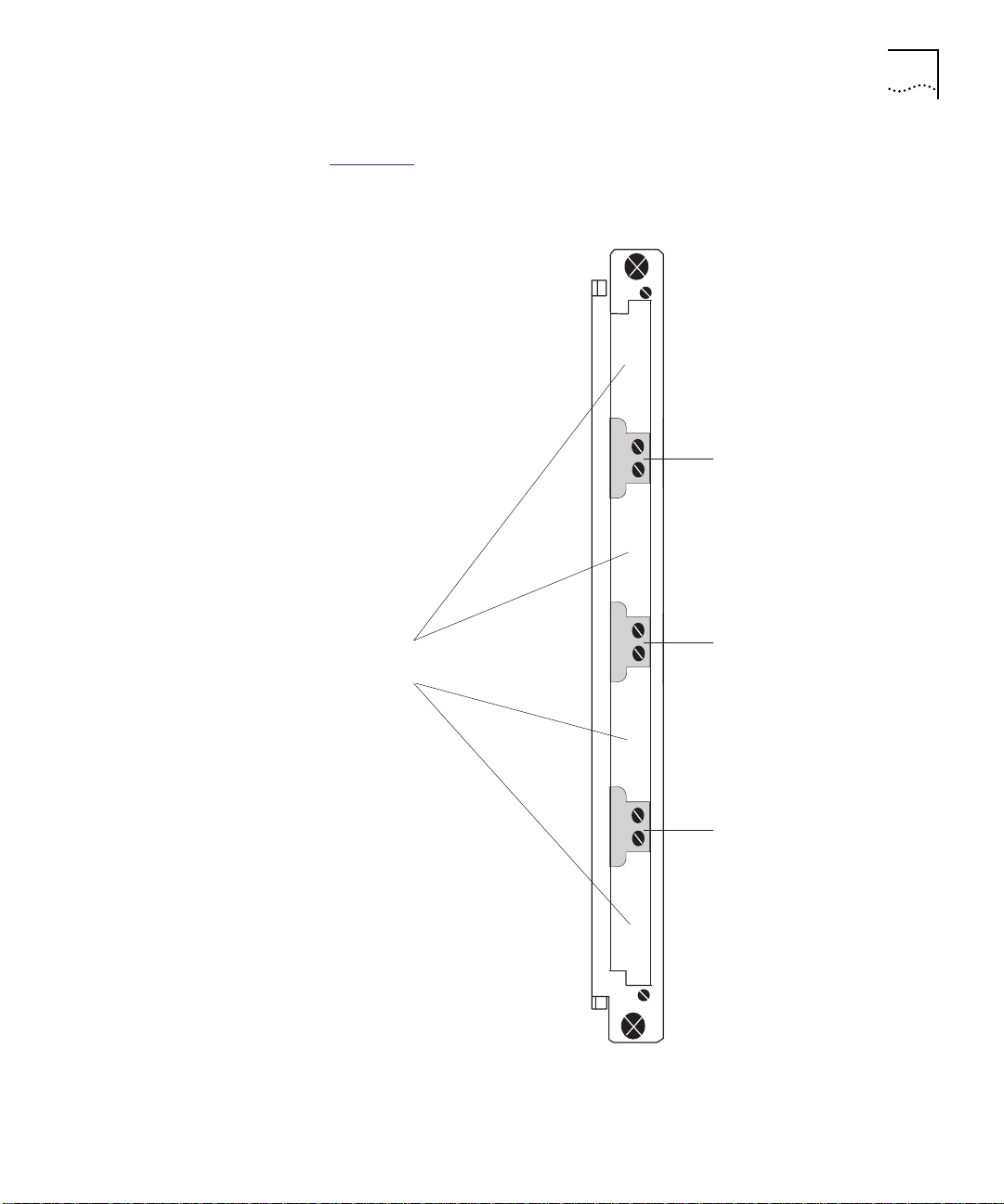
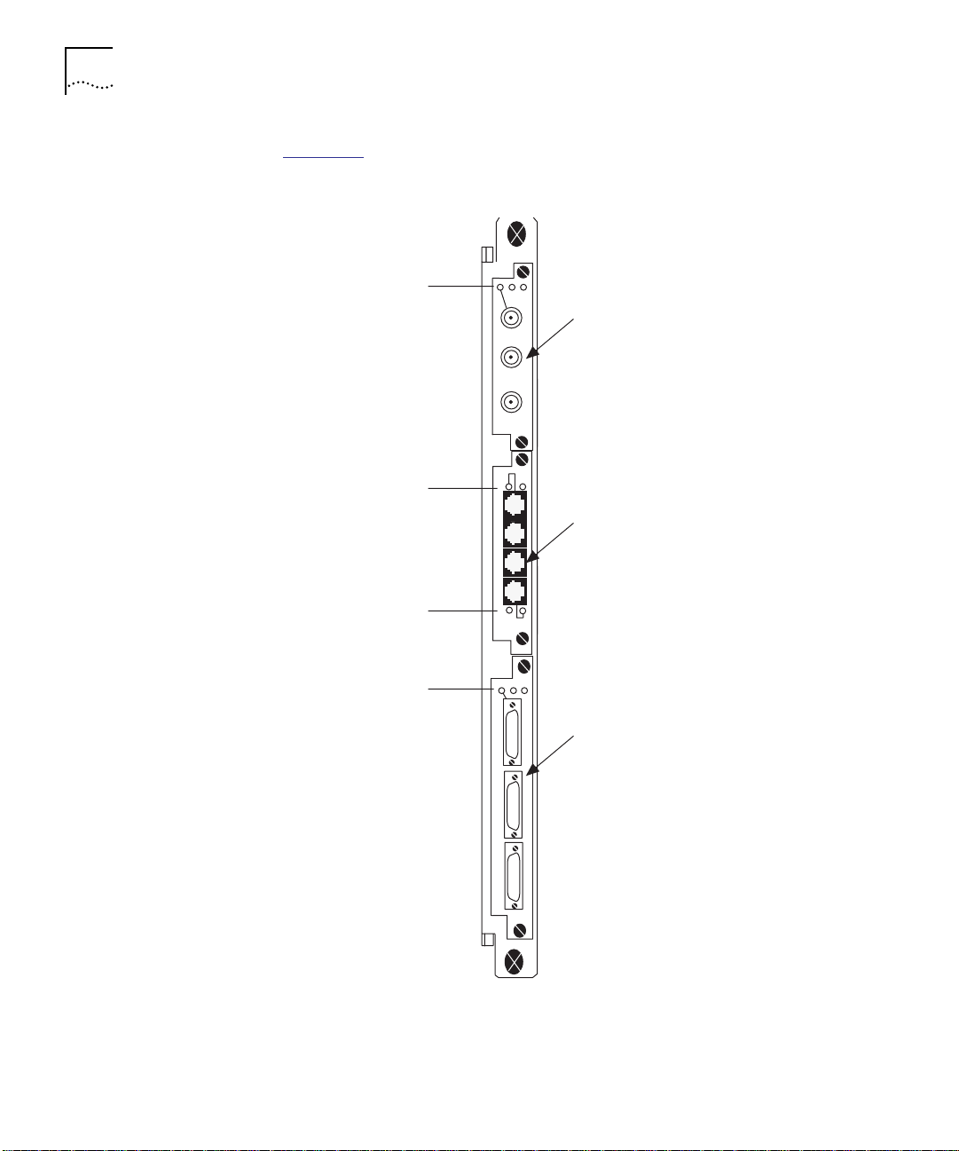
Figure 1-1 shows the EtherFlex Module with blank faceplates and no
I/O cards installed.
Removable bracket
Bays/
blank faceplates
Permanent bracket
Removable bracket
Figure 1-1 CoreBuilder 5000 EtherFlex Module Faceplate
Page 22

1-4 CHAPTER 1: INTRODUCTION
EtherFlex Module
Features
The CoreBuilder 5000 EtherFlex Module provides the following features:
■ Network Security – Supports security through the private line card
(PLC). The PLC provides continuous eavesdropping and intrusion
protection without impacting network performance.
■ Multiple Daughter Cards – Allow you to connect either network
monitor or private line cards for network management. The module
supports the following configurations:
■ 2 Private Line Cards
■ 2 daughters cards
■ 1 card of each simultaneously
■ Scalable Network Management Architecture – Allows you to
gather Ethernet and Remote Network Monitoring (RMON) network
statistics for any of the CoreBuilder 5000 backplane segments.
Supports up to 2 network monitor cards (NMC) per module for
in-depth monitoring of the network.
■ Network Statistics – All I/O cards provide support for Repeater
Management Information Base (MIB) statistics without the need for
a network monitor card.
■ Remote Diagnostics Mode – Checks driver and receiver integrity.
EtherFlex Module
Benefits
The CoreBuilder 5000 EtherFlex Module provides the following benefits:
■ Flexibility to mix and match media types using field-installable
I/O cards.
■ Per-port switching to all 8 of the CoreBuilder 5000 backplane
segments and isolated segments. Supports up to 8 segments,
simultaneously, in any combination.
■ IEEE Repeater Statistics-gathering for basic network monitoring
through the CoreBuilder 5000 security and network management
architecture.
■ Offers high port density at a low cost per port.
■ Supports per-port activity and status LEDs.
■ Maintains its own inventory and power management information in
non-volatile RAM (NVRAM).
Page 23

EtherFlex Module I/O Cards 1-5
EtherFlex Module I/O Cards
The EtherFlex Module supports several mixed-media I/O cards. All I/O
cards are field-installable. However, you must remove the EtherFlex
Module from the backplane to add, remove, or replace an I/O card on
the module.
The following I/O cards are supported:
■ BNC 10BASE-2 (Model Number 6103D-BNC)
■ RJ-45 10BASE-T (Model Number 6104D-TPP)
■ Male AUI (Model Number 6103D-AUIM)
■ Female AUI (Model Number 6103D-AUIF)
■ 10BASE-FB/FL (Model Number 6102D-FIB)
This section contains the following sections:
■ I/O Card Features and Benefits
■ I/O Card Theory of Operation
■ Maximum Number of I/O Cards Per Module
Page 24
1-6 CHAPTER 1: INTRODUCTION
Figure 1-2 shows an EtherFlex Module with three types of I/O cards
installed.
LEDs
BNC 10BASE-2 I/O Card
10BASE2
LEDs
RJ-45 10BASE-T I/O Card
LEDs
10BASET
LEDs
.
.
.
.
.
.
.
.
.
.
.
.
.
.
.
.
.
.
.
.
.
.
.
.
.
.
.
.
.
.
.
.
.
.
.
.
.
.
.
.
.
.
.
.
.
.
.
.
.
.
.
.
.
.
.
.
.
.
.
.
.
.
.
.
.
.
.
.
.
.
.
.
.
.
.
.
.
.
.
.
.
.
.
.
.
.
.
.
.
.
.
.
.
.
.
.
.
.
.
.
.
.
.
.
.
.
.
.
.
.
.
.
.
.
.
.
AUI-M
.
.
.
.
.
.
.
.
.
.
.
.
.
.
.
.
.
.
.
.
.
.
.
.
.
.
.
.
Make AUI I/O Card
Figure 1-2 I/O Cards Installed in an EtherFlex Module
Page 25

EtherFlex Module I/O Cards 1-7
I/O Card Features
and Benefits
I/O Card Theory of
Operation
The CoreBuilder 5000 EtherFlex Module I/O cards provide the following
features and benefits:
■ Multimedia Support – Flexibility to mix and match media types
using field-installable I/O cards.
■ Per-Port Switching – Per-port switching to all 8 of the CoreBuilder
5000 backplane segments and isolated segments. Supports up to
12 segments including backplane and isolated segments in any
combination.
■ Automatic Partitioning – When the number of collisions or
duration of any collision exceeds a threshold, the I/O card
automatically disables the port and then enables the port when the
I/O card detects good data.
■ IEEE Repeater Statistics – Provides IEEE Repeater
statistics-gathering for monitoring the CoreBuilder 5000 security and
network management architecture.
The EtherFlex Module I/O cards work as follows:
1 Each signal suffers a loss of power as it travels from transmitting device
to receiving device. The longer the cable length between transmitting
and receiving devices, the weaker the signal becomes during
transmission, thus lowering the chance that the receiving device can
interpret the data correctly.
2 To compensate for a weak signal, repeaters bolster the signal as it
passes through the network.
3 Regenerative repeaters sample signals along a network to determine
whether they are above or below the voltage level at which they were
originally transmitted. After each sampling, the repeaters reconstruct
the signals to their original shape and retransmit them, thus improving
data transmission.
4 Before sending the signal on to the cable (destination), each I/O card
restores the following characteristics to the signal:
■ Amplitude
■ Phase
■ Frequency
Page 26

1-8 CHAPTER 1: INTRODUCTION
Maximum Number
of I/O Cards Per
I/O Card Descriptions
Module
Table 1-1
■ I/O cards supported by the EtherFlex Module
■ Maximum number of bays occupied by each I/O card
■ Number of ports supported on each I/O card
■ Maximum number of ports supported by the EtherFlex Module
lists the:
Table 1-1 Maximum I/O Cards Supported by the EtherFlex Module
I/O Card Type
Number of I/O
Cards per
EtherFlex Module
Number
of Ports
per I/O
Card
Maximum
Ports per
EtherFlex
Module
RJ-45 10BASE-T 4 4 16
BNC 10BASE-2 4 3 12
Male AUI 2 3 6
Female AUI 2 3 6
1
10BASE-FB/FL 4 2 8
1
Refer to the section in this chapter, “Understanding Female AUI I/O Card
Limitations,” for the maximum number of Female AUI ports in a 17-slot hub.
This section describes the following I/O cards supported by the
CoreBuilder 5000 EtherFlex Module:
■ BNC 10BASE-2 I/O Card Features
■ RJ-45 10BASE-T I/O Card Features
■ Male AUI I/O Card Features
■ Understanding Female AUI I/O Card Limitations
■ 10BASE-FB/FL I/O Card Features
The CoreBuilder 5000 EtherFlex Module contains 4 bays (subslots) for
I/O cards. The module can hold up to 4 single-height or
2 double-height I/O cards at one time. Each I/O card has its own
faceplate and port status LEDs.
Page 27
I/O Card Descriptions 1-9
BNC 10BASE-2 I/O
Card Description
The CoreBuilder 5000 BNC 10BASE-2 I/O Card
(Model Number 6103D-BNC) is a single-height, 3-port repeater card
with built-in media attachment units (MAUs). Each port attaches
directly to a thin-wire (10BASE2) segment. Compatible with IEEE 802.3
specifications, this card provides full repeater functionality, allowing
you to connect up to 3 thin-wire Ethernet segments to the network.
BNC 10BASE-2 I/O Card Features
The CoreBuilder 5000 BNC 10BASE-2 I/O Card provides the following
features:
■ On-board Termination – Termination is set internal or external to
the BNC 10BASE-2 I/O Card, on a per-port basis.
■ Grounding Option – BNC connector shield grounding can either
be present or absent depending on whether the BNC jumper is
installed.
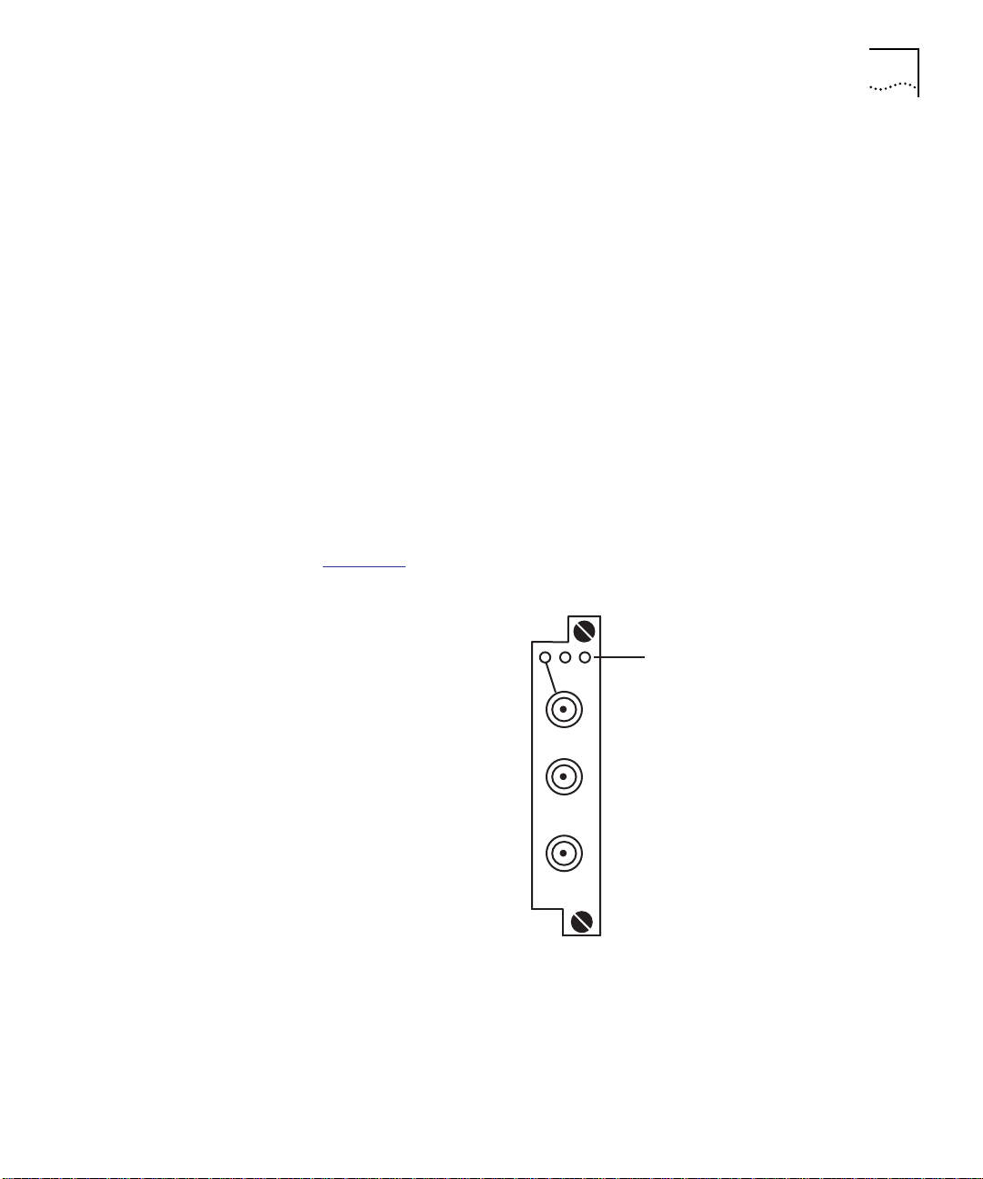
Figure 1-3
shows the BNC 10BASE-2 I/O Card faceplate and LEDs.
LEDs
10BASE2
Figure 1-3 BNC 10BASE-2 I/O Card Faceplate and LEDs
Page 28

1-10 CHAPTER 1: INTRODUCTION
RJ-45 10BASE-T I/O
Card Description
The CoreBuilder 5000 RJ-45 10BASE-T I/O Card
(Model Number 6104D-TPP)
is a single-height, 4-port repeater card
which supports networks utilizing RJ-45 connectors in 10BASE-T
installations.
The RJ-45 10BASE-T I/O Card connects up to 4 devices (PCs, terminals,
printers, modems) to the 3Com CoreBuilder 5000 Integrated System
Hub. The I/O card provides 4 twisted pair Ethernet ports which may be
switched individually to any of the CoreBuilder 5000 backplane
networks or extended (isolated) segments.
RJ-45 10BASE-T I/O Card Features
The CoreBuilder 5000 RJ-45 10BASE-T I/O Card provides the following
features:
■ Remote Diagnostic Mode – Checks driver and receiver integrity.
■ Port Redundancy – Prevents network failure by allowing you to
define a primary and secondary port in case one link fails.
■ Squelch Mode – Supports normal and low squelch settings based
on the 10BASE-T standard.
■ Auto Polarity Switching – Enables an RJ-45 10BASE-T I/O Card in
an EtherFlex Module to automatically switch the polarity of twisted
pair cabling. If, for instance, you erroneously reverse the polarity of
some twisted pair cabling while assembling it, Auto Polarity allows
you to automatically detect this problem and reverse the polarity.
■ Link Integrity – Allows you to enable or disable Link Integrity for
all ports on an RJ-45 10BASE-T I/O Card in an EtherFlex Module in
networks that comply with the 10BASE-T standard.
Page 29
I/O Card Descriptions 1-11
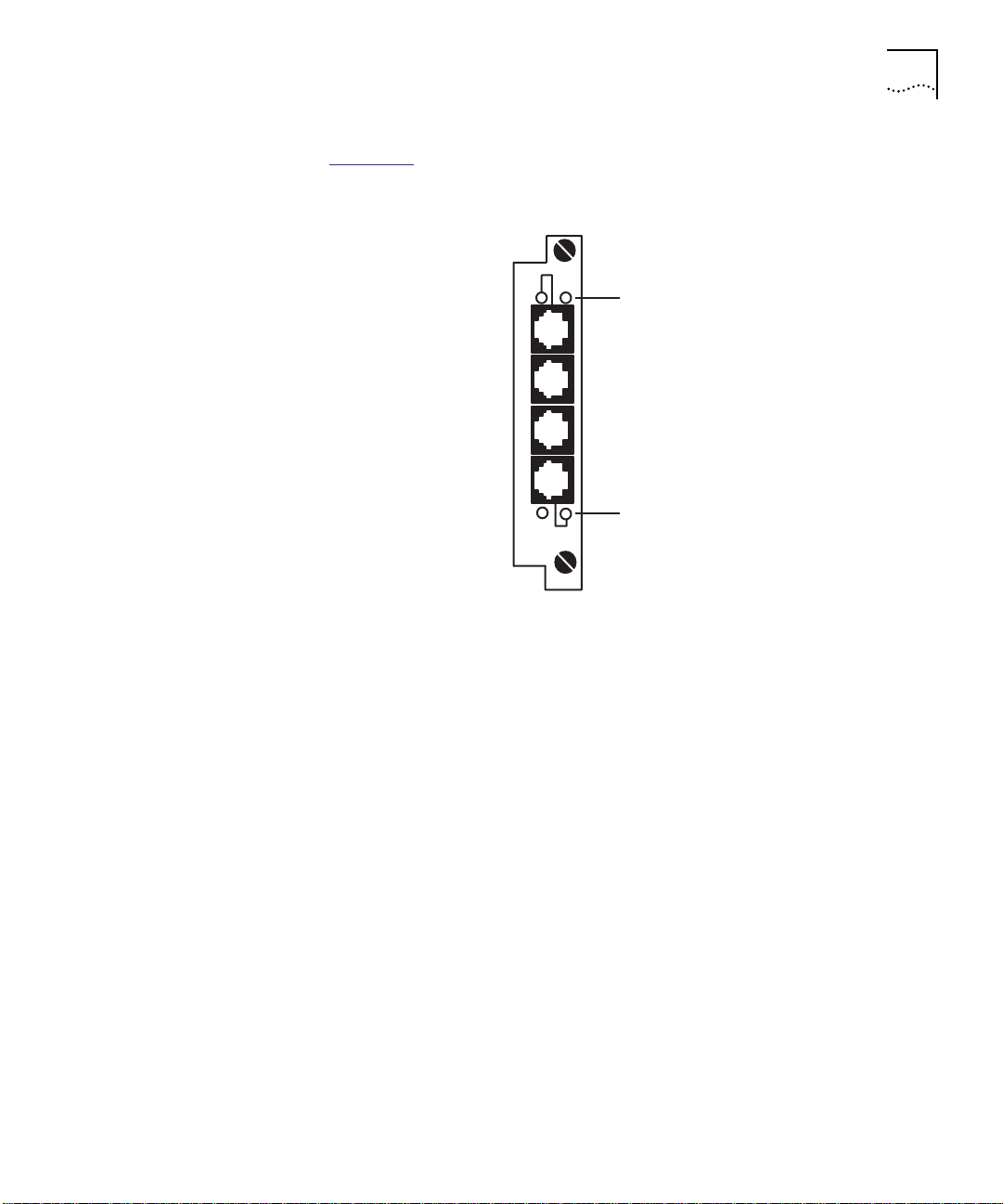
Figure 1-4 shows the RJ-45 10BASE-T I/O Card and LEDs.
LEDs
LEDs
10BASET
Male AUI I/O Card
Description
Figure 1-4 RJ-45 10BASE-T I/O Card Faceplate and LEDs
The CoreBuilder 5000 Male AUI I/O Card (Model Number 6103D-AUIM)
is a double-height transceiver, 3-port repeater card. Compatible with
IEEE 802.3 specifications, this I/O card is designed for attaching
computers, bridges, routers, and repeaters directly to your
CoreBuilder 5000 system through an AUI cable.
Male AUI I/O Card Features
The Male AUI I/O Card provides the following features:
■ Port Redundancy – Prevents network failure by allowing you to
define a primary and secondary port in case one link fails.
■ SQE Test – Provides an SQE (Software Quality Engineering) test for
repeater compatibility.
Page 30
1-12 CHAPTER 1: INTRODUCTION
Figure 1-5 shows the Male AUI I/O Card faceplate and LEDs.
LEDs
.
.
.
.
.
.
.
.
.
.
.
.
.
.
.
.
.
.
.
.
.
.
.
.
.
.
.
.
.
.
.
.
.
.
.
.
.
.
.
.
.
.
.
.
.
.
.
.
.
.
.
.
.
.
.
.
.
.
.
.
.
.
.
.
.
.
.
.
.
.
.
.
.
.
.
.
.
.
.
.
.
.
.
.
.
.
.
.
.
.
.
.
.
.
.
.
.
.
.
.
.
.
.
.
.
.
.
.
.
.
.
.
.
.
.
.
.
.
.
.
.
.
.
.
.
.
.
.
.
.
.
.
.
.
.
.
.
.
.
.
.
.
.
.
AUI-M
Figure 1-5 Male AUI I/O Card Faceplate and LEDs
Page 31

I/O Card Descriptions 1-13
Female AUI I/O Card
Description
The CoreBuilder 5000 Female AUI I/O Card
(Model Number 6103D-AUIF) is a double-height, 3-port repeater card
that attaches Ethernet segments directly to your CoreBuilder 5000
system using an AUI cable and external transceivers. Compatible with
IEEE 802.3 specifications, the Female AUI I/O Card provides a way to
connect any Ethernet segment running on 10BASE-5 transceiver cable
to your network.
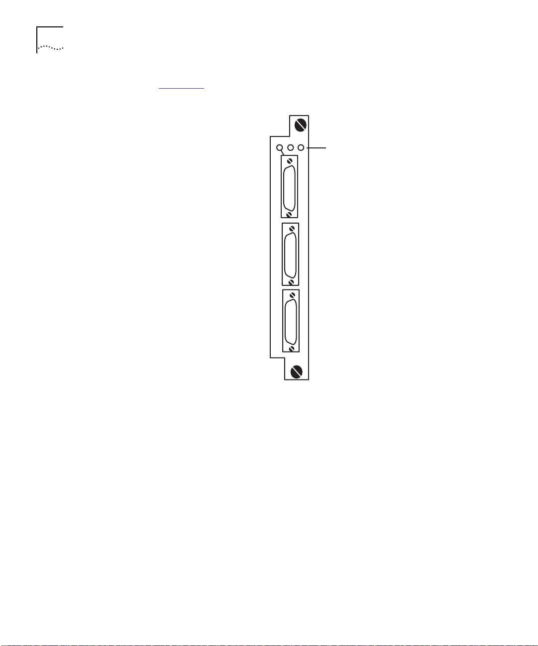
Figure 1-6
shows the Female AUI I/O Card and LEDs.
LEDs
AUI-F
Figure 1-6 Female AUI I/O Card Faceplate and LEDs
Understanding Female AUI I/O Card Limitations
The CoreBuilder 5000 Female AUI I/O Card uses significantly more
+12 Volt power than other I/O cards. As a result, there is a limitation on
the number of Female AUI ports that can exist in a CoreBuilder 5000
17-slot hub. The limitation to the number of ports configured on a
Female AUI I/O Card depends on the number of power supplies used in
that hub.
Page 32

1-14 CHAPTER 1: INTRODUCTION
Follow the guidelines outlined in Table 1-2 when installing a Female
AUI I/O Card in an EtherFlex Module.
Table 1-2 Female AUI I/O Card Limitations
Maximum Number
Number of Power Supplies Available
4 (with no redundant power supply) 23
4 (with 1 redundant power supply) 15
of Female AUI Ports
The maximum number of Female AUI I/O cards is 23 for CoreBuilder
5000 or ONline hubs in any combination.
If you are unsure how well your configuration of the Female AUI I/O
Card accommodates these guidelines, contact your supplier or 3Com
Technical Support.
10BASE-FB/FL I/O
Card Description
The CoreBuilder 5000 10BASE-FB/FL I/O Card
(Model Number 6102D-FIB) is a single-height, 2-port repeater,
autosensing I/O card that complies with the IEEE 802.3 standard. The
I/O card’s autosensing capability allows you to connect fiber to the
desktop (10BASE-FL) or fault-tolerant backbones (10BASE-FB). The
module determines if one end of the fiber link is 10BASE-FB or
10BASE-FL.
You can mix FB and FL networks on the same 10BASE-FB/FL I/O card.
10BASE-FB/FL I/O Card Features
The 10BASE-FB/FL I/O Card provides the following features:
■ Remote Diagnostic Mode – Checks driver and receiver integrity.
■ Port Redundancy – Prevents network failure by allowing you to
define a primary and secondary port in case one link fails.
■ Autosensing – Automatically configures the 10BASE-FB/FL ports on
the EtherFlex Module to the same protocol the network is running.
Page 33

Sample Etherflex Module Application 1-15
Figure 1-7 shows the 10BASE-FB/FL I/O Card faceplate and LEDs.
Sample Etherflex Module Application
RX
1
TX
RX
2
TX
FB/FL
LEDs
Figure 1-7 10BASE-FB/FL I/O Card Faceplate and LEDs
This section shows a sample application for the EtherFlex Module.
Figure 1-8
shows an EtherFlex Module application with the following
I/O cards installed:
■ RJ-45 10BASE-T – Utilizing 2 of 4 ports
■ BNC 10BASE-2 – Utilizing 3 ports
The sample application shows the following:
■ Two PCs connected directly to an RJ-45 10BASE-T I/O Card using a
twisted pair RJ-45 cable.
■ Three 10BASE-2 segments connected to a BNC 10BASE-2 I/O Card.
Each segment is grounded and terminated with 50 ohm termination
on both ends.
In Figure 1-8
■ The first and third segments (Ports 1 and 3) are externally
:
terminated. You do not set the BNC jumpers.
■ The second segment (Port 2) terminates at the port. When the
BNC port serves as the segment end point, install termination
through jumper settings on the BNC 10BASE-2 I/O Card.
Page 34

1-16 CHAPTER 1: INTRODUCTION
EtherFlex Module
RJ-45 10BASE-T
I/O Card
Port 1
Figure 1-8 shows a sample EtherFlex application.
RJ-45 cable
Where to Go From Here
Port 3
External
termination
Port 2
External
termination
CoreBuilder 50 00 hub
PC
PC
PC
PC
PC
PCPC
BNC 10BASE-2 I/O Card
PC
PC
10BASE2
Printer
PC
PC
PC
PC
10BASE2
Printer
10BASE2
Printer
External
termination
External
termination
External
termination
Figure 1-8 EtherFlex Application With RJ-45 10BASE-T and
BNC 10BASE-2 I/O Cards
Once you are familiar with the CoreBuilder 5000 EtherFlex Module,
evaluate the environment in which you plan to use the module and go
to Chapter 2, Designing and Expanding the Network
. Chapter 2
describes cabling considerations and configuration examples specific to
the EtherFlex Module in the CoreBuilder 5000 Integrated System Hub.
Page 35

DESIGNING AND EXPANDING THE
2
NETWORK
This chapter describes how to configure networks that use the
CoreBuilder
EtherFlex Module, and I/O cards.
This chapter contains the following sections:
■ Understanding General Network Configuration Rules
■ Configuring Fiber Backbone, Twisted Pair to-the-Desk
■ Configuring Twisted Pair Backbone, Twisted Pair to-the-Desk
■ Connecting an Ethernet Segment Using a Male AUI I/O Card
■ Using Patch Panels
■ Setting Redundant Links
■ Where to Go From Here
CAUTION: To ensure proper operation, install all equipment using only
approved cables. Refer to Appendix A
on connector and cable requirements.
™
5000 Integrated System Hub, the CoreBuilder 5000
, Specifications, for information
Understanding General Network Configuration Rules
This section describes general rules for configuring an Ethernet network
using fiber as the backbone medium and twisted pair as the horizontal
medium (connection to printers, PC). It also provides rules to ensure
that your network configuration conforms to distance limitations
imposed by Ethernet and networking equipment.
The following topics are discussed:
■ Before Configuring Your Network
■ Basic Network Rules
■ LAN Product Distances
Page 36

2-2 CHAPTER 2: DESIGNING AND EXPANDING THE NETWORK
Before Configuring
Before configuring the network, consider your:
Your Network
■ Network size from end to end:
■ 100 meters
■ 1000 meters
■ 4000 meters
■ Greater than 4000 meters
■ Plans for expansion. Once the network expands beyond a certain
size, you may need to add a switch or other internetworking device.
Basic Network Rules Table 2-1
■ Seven basic network rules to keep in mind when you construct
your network
■ 3Com Corporation’s recommendations for these rules
For hardware-specific information on the EtherFlex Module, refer to
Appendix A
Table 2-1 Seven Basic Network Rules
Rule Definition Recommendations/Notes
1 If possible, use 10BASE-FB
as the backbone medium.
2 Wire the backbone in a
3 Use the maximum Fiber
star topology for proper
fault isolation.
Ethernet network
diameter, which is
4200 meters of fiber
cable.
lists:
, Specifications.
Use 62.5 micron cable to conform with IEEE 10BASE-F and
ANSI FDDI standards.
Use ST-type connectors.
Make sure to lay extra fiber cables. The extra cost is small
and you need them as your network grows.
The star topology conforms to Ethernet and FDDI wiring.
Ensure that you run at least 2 fiber strands to each
backbone connection.
4200 meters is the maximum distance between any
2 transceivers on the network.
4200 meters does not include the transceiver cable (that
is, drop or patch cable) that connects a device with an
external transceiver. Transceiver cables can extend up to
50 meters. Thus, total network diameter can be as much
as 4300 (4200 m + 2 * 50 m) between any 2 nodes.
Page 37

Understanding General Network Configuration Rules 2-3
Table 2-1 Seven Basic Network Rules (continued)
Rule Definition Recommendations/Notes
4 Be aware that certain
LAN devices on the
network shrink the
maximum Fiber Ethernet
network diameter to less
than 4200 meters.
5 Assume that 1 meter of
coaxial or twisted pair
cable is equal to 1 meter
of fiber cable.
6 Ensure the fiber link
distances do not exceed
the limits imposed by the
optical power budget.
7 When in doubt about your
network distance, use a
switch or bridge.
Many LAN products delay the signal that travels through
them. This is known as equivalent distance. Each
microsecond delay:
Reduces the maximum link distance
Shrinks the network diameter by approximately
200 meters of fiber cable
Table 2-2
A conservative rule. For example, the actual equivalence is
about 1.1 meters of coaxial cable for each meter of fiber
cable. For simplicity, assume 1 meter.
For 62.5 micron cable, you can use up to 4000 meters
point-to-point using CoreBuilder 5000 or ONline Fiber
Modules. If you have poor quality cable or cross several
patch panels, you may have to sacrifice some distance in
cable length.
Some older, Ethernet fiber optic products are less
powerful than CoreBuilder 5000 Fiber Module optics. If
connecting to an Ethernet fiber optic product, remember
that the least powerful device determines the maximum
point-to-point distance.
If you are not certain if you have exceeded allowable
network distances, use a bridge to extend the network.
lists equivalent distances for 3Com products.
Page 38

2-4 CHAPTER 2: DESIGNING AND EXPANDING THE NETWORK
LAN Product
Distances
When you configure your network, each installed product reduces the
network diameter distance. Table 2-2
lists the LAN product equivalent
distances required for each LAN product installed.
Table 2-2 LAN Product Equivalent Distances
Equivalent Distance
LAN Product
CoreBuilder 5000 and ONline Ethernet 10BASE-T Modules 585
Incoming signal to TP port 420
Outgoing signal from TP port 165
CoreBuilder 5000 and ONline Ethernet 10BASE-FB
Modules
Incoming signal to fiber port 140
Outgoing signal from fiber port 50
CoreBuilder 5000 and ONline Ethernet 10BASE-FL Module 560
Incoming signal to fiber port 330
Outgoing signal from fiber port 230
CoreBuilder 5000 and ONline Ethernet Transceiver
Module
10BASE-FB Star Coupler (8 or 14 port) 180
CoreBuilder 5000 and ONline Ethernet BNC Module 900
Incoming signal to BNC port 450
Outgoing signal from BNC port 450
CoreBuilder 5000 and ONline Ethernet Repeater Module 800
Incoming signal to AUI port 600
Outgoing signal from AUI port 200
IEEE Repeater 800
(meters)
190
0
Page 39

Configuring Fiber Backbone, Twisted Pair to-the-Desk 2-5
Configuring Fiber
Backbone, Twisted
Pair to-the-Desk
Fiber Backbone
Configuration Rules
This section describes:
■ Fiber Backbone Configuration Rules
■ Fiber Backbone, Twisted Pair to-the-Desk Configuration Example
■ Verifying Fiber Backbone Configuration
When you configure a network with unshielded twisted pair (UTP)
cabling to the desk and fiber for the backbone, the following rules
apply:
■ Add a bridge if you will exceed 4 full repeater hops.
■ If traffic travels into a port on any repeater-based module and
out the backplane, then the module counts as a ½-repeater hop.
■ If traffic travels into the module through one port and out
another port on the same or a different module, then the
module counts as 1 full repeater hop.
■ The equivalent fiber distance for the EtherFlex 10BASE-FB I/O Card
or Ethernet 10BASE-FB Modules (see Table 2-2
■ 140 meters for signals that enter a 10BASE-FB port at the front
) is:
panel
■ 50 meters for signals that internally enter a 10BASE-FB Module
through the CoreBuilder 5000 hub backplane
■ The equivalent fiber distance for the EtherFlex 10BASE-T I/O Card or
Ethernet 10BASE-T Modules (see Ta b l e 2 - 2
■ 420 meters for signals that enter the EtherFlex 10BASE-T port at
) is:
the front panel
■ 165 meters for signals that internally enter a 10BASE-T port
through the CoreBuilder 5000 hub backplane
For each pair of EtherFlex 10BASE-T I/O Cards that a signal travels
through, deduct a fiber equivalent distance of 585 meters (420 m +
165 m = 585 m) from the overall allowable network diameter. You
must also deduct the fiber equivalent distance if a signal enters the
EtherFlex 10BASE-T I/O Card through one port and exits another port
of the same EtherFlex 10BASE-T I/O Card. The fiber equivalent distance
counts as 585 meters of fiber equivalent distance and as a full repeater
hop.
Page 40

2-6 CHAPTER 2: DESIGNING AND EXPANDING THE NETWORK
Fiber Backbone,
Twisted Pair
to-the-Desk
Configuration
Example
Fiber
backbone
1000 m
The sample configuration shown in Figure 2-1 uses EtherFlex
10BASE-FB I/O Cards to connect hubs and EtherFlex 10BASE-T I/O Cards
to connect to transceivers. Refer to the next page for a detailed
explanation of configuration distances.
1
2
4
3
6
5
8
7
10
9
1
2
3
4
5
6
7
8
9
10
1
2
4
3
6
5
8
7
10
9
1
2
3
4
5
6
7
8
9
10
500 m
Fiber backbone
1
2
4
3
6
5
8
7
10
9
1
2
3
4
5
6
7
8
9
10
Hub A
Hub B
Hub C
Unshielded twisted pair
100 m
A
Unshielded twisted pair
B
75 m
Unshielded twisted pair
C
Configuration Distance
1. Maximum Diameter:
2. Equivalent Distances:
Hub A:
Hub B:
Hub C:
Total:
3. Amount of cable between
transceivers:
Total:
4. Remaining Distance:
470 m
305 m
190 m
965 m
1000 m
100 m
500 m
75 m
4200 m
1675 m
1560 m
Figure 2-1 Sample Configuration Distance Calculation
Page 41

Configuring Twisted Pair Backbone, Twisted Pair to-the-Desk 2-7
Verifying Fiber
Backbone
Configuration
To determine if your network configuration is legal:
1 Begin with 4200 meters (m).
2 Identify the two transceivers that are the greatest fiber equivalent
distance apart. In Figure 2-1
, 10BASE-T Transceivers A and B are the
farthest apart.
3 Determine the sum of each hub’s equivalent distance using the
distances listed in Table 2-2
. For example, Hub A has an equivalent
distance of 470 m. This total represents the sum of the incoming signal
to the UTP port (420 m) and the outgoing signal from the fiber port
(50 m). Refer to Figure 2-1
for details.
4 Subtract the total equivalent distance of each hub located between
transceivers A and B (965 m) from the maximum network diameter
(4200 m). In this case, the subtotal is 3235 m.
5 Determine the total amount of cable between transceivers A and B
(1675 m) and subtract this number from the subtotal determined in
step 4 (3235 m).
The remaining distance equals 1560 m.
For the configuration shown in Figure 2-1
to function properly, the fiber
equivalent distance between Transceiver A and Transceiver B must be
less than 4200 meters. As a result of the calculation above,1560 meters
remain for expansion.
Configuring
Twisted Pair
Backbone, Twisted
Pair to-the-Desk
This section describes:
■ TTwisted Pair Backbone Configuration Rules
■ Twisted Pair Backbone, Twisted Pair to-the-Desk Configuration
Example
■ Verifying a Twisted Pair Backbone Configuration
Page 42

2-8 CHAPTER 2: DESIGNING AND EXPANDING THE NETWORK
Twisted Pair
Backbone
Configuration Rules
Twisted Pair
Backbone, Twisted
Pair to-the-Desk
Configuration
Example
When you configure a network with twisted pair cabling to the desk
and twisted pair for the backbone, the following rules apply:
■ Add a bridge if you have more than 8 EtherFlex modules serially
connected. Each bridge creates a subnetwork. Each subnetwork can
have its own 4200 meter network diameter.
■ If traffic travels into a port on any repeater-based module and
out the backplane, then the module counts as a ½-repeater hop.
■ If traffic travels into the module through one port and out
another port on the same or a different module, then the
module counts as 1 full repeater hop.
Because of the Ethernet 4-repeater rule, do not put more than 8
CoreBuilder 5000 Ethernet Modules in the path between any
2 transceivers. An exception to this is the CoreBuilder 5000 10-Port
FB Module and EtherFlex Modules with 10BASE-FB/FL I/O cards
configured as FB. These configurations allow more than 8 modules in
the path between 2 transceivers.
Figure 2-2 illustrates an example of a twisted pair network.
B
100 m
A
100 m
100 m
C
100 m
Figure 2-2 Example of a Twisted Pair Network
D
50 m
Page 43

Configuring Twisted Pair Backbone, Twisted Pair to-the-Desk 2-9
Verifying a Twisted Pair
Backbone
Configuration
Although fiber cable is not used in the configuration illustrated in
Figure 2-2
, you can calculate the fiber equivalent distance as follows:
1 Total amount of cable between workstations:
100 m + 100 m + 100 m + 100 m + 50 m = 450 m.
2 Total equivalent distance of the EtherFlex 10BASE-T Modules:
Each hub has an equivalent distance of (420 m + 165 m) or 585 m
Four hubs with a total equivalent distance of (585 m * 4) or 2340 m
exist.
3 Total equivalent distance: 450 m + 2340 m = 2790 m.
1
Incoming signal to the UTP port on each hub = 420 m. Outgoing
signal from the UTP port on each hub = 165 m. Refer to Table 2-2
more information on LAN product equivalent distances.
Although the twisted pair network example in Figure 2-2
uses only
CoreBuilder 5000 EtherFlex 10BASE-T Modules, it is also possible to use
other 10BASE-T modules.
Because the total equivalent distance (2790 meters) is less than
4200 meters, Figure 2-2
illustrates a legitimate configuration.
1.
for
Page 44

2-10 CHAPTER 2: DESIGNING AND EXPANDING THE NETWORK
Connecting an
Ethernet Segment
Using a Male AUI
I/O Card
This section shows a configuration in which the Male AUI I/O Card in
an EtherFlex Module is connected to network PCs.
Figure 2-3
shows a network setup of an Ethernet segment connecting
to a hub containing an EtherFlex Module with a Male AUI I/O Card.
CoreBuilder 5000 hub
1
2
4
3
6
5
8
7
10
9
1
2
3
4
5
6
7
8
9
10
Fiber backbone
1
2
4
3
6
5
8
7
10
9
1
2
3
4
5
6
7
8
9
10
50 m
AUI cable
CoreBuilder 5000 hub
3 m
AUI cable
PC
PC
Figure 2-3 Ethernet Segment Connected to EtherFlex Module
When you connect an AUI port to a device, the minimum AUI cable
distance is 3 meters and the maximum is 50 meters.
Page 45

Using Patch Panels 2-11
Using Patch Panels Patch panels make cable management simple when used in a
rack-mounted hub. However, patch panels weaken signals that pass
through them, thereby reducing achievable link distances.
3Com assumes the use of 1 patch panel in the 100 meter link distance
calculations specified in the examples in this guide. Each additional
patch panel in the link reduces the 100 meter link distance by
approximately 10 meters.
In the example shown in Figure 2-2
, if you used 2 patch panels
between the upper right PC and the upper right hub, you would have
to shorten the link distance of 100 meters to 90 meters. This is because
the maximum allowable link distance on 24-gauge wire (using
10BASE-T signaling with 2 intervening patch panels) is 100 meters
minus approximately 10 meters.
A patch panel installed between the lower right PC and the lower left
hub in Figure 2-2
does not affect the link because it is only 50 meters
away. Patch panels only affect lengths greater than 90 meters.
Page 46

2-12 CHAPTER 2: DESIGNING AND EXPANDING THE NETWORK
Setting Redundant Links
EtherFle x
Module
When you set up a redundant twisted pair link between ports on
CoreBuilder 5000 hubs, you prevent any possible network failure.
Figure 2-4
shows two examples of a redundant configuration using
RJ-45 10BASE-T and Male AUI I/O Cards in an EtherFlex Module.
CoreBuilder 5000 hub
T wisted pair
cable
Twisted pair
cable
CoreBuilder 5 000 hub
EtherFle x
Modules
AUI cable
Setting redu nd ant links between 2
ports on 1 I/O card on an EtherFlex
Module
Figure 2-4 Redundant Configurations
You can also enable redundancy between ONline modules in a
CoreBuilder 5000 Integrated System Hub.
Setting redundant links between 2 ports
on different I/O cards on 2 EtherFlex
Modules
Page 47

Setting Redundant Links 2-13
Setting Redundancy
Between Two Ports
on One EtherFlex
Module
Setting Redundancy
Between Two
EtherFlex Modules
To set link redundancy between 2 ports on 1 RJ-45 10BASE-T I/O Card
in an EtherFlex Module:
1 Connect 2 links to 2 ports on the module.
2 Use the SET PORT MODE REDUNDANT command to specify the primary
link port and the backup link port.
For example, if you set up a redundant link using the following
command:
SET POR T 8.1 MODE REDUNDANT 8.3
Port 1 in slot 8 becomes the primary link and port 3 in slot 8 becomes
the backup link.
To set link redundancy between 2 ports on different I/O cards in 2
EtherFlex Modules:
1 Connect 2 links to 2 ports between the modules.
2 Use the SET PORT MODE REDUNDANT command to specify the primary
link port and the backup link port.
For example, if you set up a redundant link using the following
command:
SET PORT 12.3 MODE REDUNDANT 8.2
Port 3 in slot 12 becomes the primary link and port 2 in slot 8 becomes
the backup link.
Only RJ-45 10BASE-T twisted pair, Male AUI, and 10BASE-FB/FL I/O
Cards support this feature.
CAUTION: Redundancy on the EtherFlex Module is a management
module software function. Consequently, a network loop could occur
if the module is set to redundant mode and it is powered down and
then up without a 3Com management module in the hub.
Page 48

2-14 CHAPTER 2: DESIGNING AND EXPANDING THE NETWORK
Once redundancy is configured, a switchover to the backup link occurs
under two conditions:
■ Link failure
■ Port partition
Once the switchover occurs and the backup link becomes operational,
the system automatically performs a switchover back to the primary link
once the problem is resolved.
Although you can configure redundancy between 2 ports on 1 module,
you should configure redundancy between 2 ports on 2 different
modules. This provides additional protection if, for example, one of the
modules fails.
Refer to the CoreBuilder 5000 Distributed Management Module User
Guide for more information on setting redundancy between module
ports.
Where to Go From Here
Once you complete this chapter, go to Chapter 3. Chapter 3, Installing
the Module and I/O Cards, describes installation procedures, explains
how to set the DIP switches, and explains how to monitor the front
panel using LEDs.
Page 49

INSTALLING THE MODULE AND
3
I/O CARDS
This chapter describes how to install the CoreBuilder™ 5000 EtherFlex
Module and I/O cards. A module reference card for the EtherFlex
Module (Document Number 17-00620) lists the DIP switch settings,
EtherFlex Module management commands, LED indicators, and other
module information. Store the card in the CoreBuilder 5000 reference
binder in the Reference Card area.
This chapter contains the following topics:
■ Precautionary Procedures
■ General Installation Rules
■ Quick Installation
■ Unpacking Procedures
■ Setting the DIP Switches
■ BNC 10BASE-2 I/O Card Jumpers
■ Connecting Module Daughter Cards
■ Installing I/O Cards
■ Installing the Module
■ Monitoring the Front Panel
■ Verifying LED and Network Operation
■ Where to Go From Here
CAUTION: Read the precautionary procedures before unpacking the
module.
Page 50

3-2 CHAPTER 3: INSTALLING THE MODULE AND I/O CARDS
Precautionary Procedures
Electrostatic discharge (ESD) can damage static-sensitive devices on
circuit boards. Follow these precautions when you handle the EtherFlex
Module and any I/O card that is installed on the module.
CAUTION: Do not remove the board from its antistatic shielding bag
until you are ready to inspect or install it.
CAUTION: Handle the board by the faceplate only.
Use one of the following proper grounding techniques when you install
the EtherFlex Module and I/O cards:
■ Use a foot strap and grounded mat or wear a grounded static
discharge wrist strap.
■ Touch the grounded rack or other source of ground just before you
handle the module and I/O cards.
Page 51

General Installation Rules 3-3
General Installation Rules
This section describes general rules to follow when installing and
replacing I/O cards on an EtherFlex module, as follows:
■ If you want to remove an I/O card from an EtherFlex carrier module,
you must:
■ Disable all ports on that module.
■ Reconfigure the module after you re-install it.
This is because each physical port on the module is associated with a
logical port in a top-to-bottom sequence.
For example, if 3 EtherFlex I/O cards are installed in a hub and each
card contains 3 ports (BNC I/O Card), ports 1 to 3 are associated with
the top-most I/O card, ports 4 to 6 with the center I/O card, and ports
7 to 9 with the bottom I/O card. If you remove the middle card, the
bottom card takes on ports 4 to 6 attributes and ports 7 to 9 no longer
exist.
■ Install daughtercards on the EtherFlex module before you install
I/O cards.
■ If you insert different types of I/O cards after configuring the
module, you must reconfigure the module if the number of ports
or media type changes.
■ If you replace an I/O card and the existing I/O card port number and
media type remain constant, then the module configuration does
not change.
■ I/O card ports are numbered sequentially from top to bottom on an
EtherFlex module. When you replace or install I/O cards, existing I/O
cards installed in the bays below the newly-installed I/O card must
be reconfigured.
■ When using the SHOW MODULE command, follow these guidelines
when numbering the subslot parameters:
■ EtherFlex module occupies subslot 1.
■ Daughtercards occupy subslots 2 and 3.
■ I/O cards in the EtherFlex module occupy subslots 4, 5, 6, and 7
(depending on the type of I/O card installed). Male AUI and
Female AUI I/O cards occupy subslots 4 and 6.
EtherFlex modules can occupy any slot in the hub.
Page 52

3-4 CHAPTER 3: INSTALLING THE MODULE AND I/O CARDS
Quick Installation Table 3-1 outlines the steps for the installation of your module and
I/O cards. If you are familiar with installing CoreBuilder 5000 modules,
use this table as a checklist. Otherwise, consult the remainder of this
chapter.
Table 3-1 Quick Installation Checklist
Step Procedure Chapter/Section
1 Verify that your network complies with the
basic rules for network design.
2 Unpack the module and I/O cards. Chapter 3, Unpacking
3 Configure the DIP switch settings. If you
have a network management module
installed in the hub, configure the module
using the management commands
described later in this chapter.
4 Insert I/O cards onto the EtherFlex Module.
5 Attach the Network Monitor Card or
6 Establish connections from the EtherFlex
7 Enter the SHOW POWER1 command at the
8 Verify LED status for normal operation. Chapter 3, Verifying LED
1
Refer to the CoreBuilder 5000 Integrated System Hub Installation and Operation Guide for
Tighten the faceplate screws of each I/O
card.
Private Line Card to the EtherFlex Module.
Module to devices using the appropriate
connectors and cabling.
command line of the terminal. This
command displays current power
requirements for the hub.
details on hub power requirements.
Chapter 2, Designing and
Expanding the Network
Procedures
Chapter 3, Setting the DIP
Switches or Chapter 4,
Configuring the EtherFlex
Module and I/O Cards
Chapter 3, Installing I/O
Cards
Chapter 3, Connecting
Module Daughter Cards
Chapter 3, Installing the
Module
Chapter 3, Installing the
Module
and Network Operation
For information about potential problems, consult the troubleshooting
techniques in Chapter 5
.
Page 53

Unpacking Procedures 3-5
Unpacking Procedures
To unpack the EtherFlex Module and I/O cards:
1 Verify that the EtherFlex Module (Model Number 6104M-MOD) is the
model you ordered by checking the model number listed on the side of
the shipping carton.
Note that the product model number printed on the shipping box
differs from the model number on the product. The model number on
the shipping box contains the prefix ’3C9’.
2 Verify that the I/O cards are the models that you ordered by checking
the Model Number listed on the side of the shipping carton.
3 Remove the EtherFlex Module and I/O cards from the shipping carton.
4 Remove the module and I/O cards from the antistatic shielding bag and
inspect them for damage.
Always handle the EtherFlex Module and the I/O cards by the faceplate,
being careful not to touch the components. If the module or I/O cards
appear to be damaged, return them to the antistatic shielding bag,
repack them in the shipping carton, and contact your local supplier.
Keep the shipping carton and antistatic shielding bag in which your
module and I/O cards were shipped for future storage or shipment.
Record the serial number of your EtherFlex Module and any I/O cards
you received. The Hub Planning Chart (located in the CoreBuilder 5000
reference binder) and the Module Planning Chart (supplied with your
module) are provided for this purpose.
Before You Begin Before installing the EtherFlex Module and I/O cards, be sure that the
module is equipped with:
■ 4 blank panels on the front of the module
■ 2 removable brackets
■ 2 screws per panel
■ 4 standoffs and screws
Standoffs with the screws are attached to the module. There is
1 standoff per bay (Figure 3-7
).
Page 54

3-6 CHAPTER 3: INSTALLING THE MODULE AND I/O CARDS
Place all unused blank faceplates, screws, and brackets in a safe place.
You will need them for future use.
Setting the DIP Switches
If you are using a management module and do not plan to use the DIP
configuration command, skip the section Setting the DIP Switches
in this chapter and go to one the following sections:
■ Section BNC 10BASE-2 I/O Card Jumpers if you are going to set
jumpers on the BNC 10BASE-2 I/O Card
■ Section Connecting Module Daughter Cards if you are going to
install an Ethernet Network Monitor Card or a Private Line Card
The CoreBuilder 5000 EtherFlex Module has an 8-position DIP switch.
All of the DIP switch settings on the EtherFlex Module are ignored if an
appropriate CoreBuilder 5000 network management module
(for example, DMM 2.2 or later) is already installed in the hub. Use
network management commands, rather than the DIP switches, to
configure the module.
This section contains the following information:
■ DIP Switch Features
■ Setting the DIP Switches
■ DIP Switch Definition
DIP Switch Features Use the DIP switch to:
later
■ Configure the module to a CoreBuilder 5000 backplane network
■ Choose the primary module configuration:
■ Non-volatile RAM configuration (software configuration)
■ DIP Segment selection (DIP-specified module configuration)
You cannot assign ports to different networks simultaneously using the
DIP switches on the EtherFlex Module. You must use network
management commands.
Page 55

Setting the DIP Switches 3-7
Setting the DIP
Switches
To set the module to access the DIP switch settings when using a
management module, issue the SET DEVICE DIP_ CONFIGUR ATIO N
ENABLE command from the management module.
If a CoreBuilder 5000 network management module is not installed in
your hub, your hub configuration defaults to the DIP switch settings on
the module.
Figure 3-1
shows the DIP switch location on an EtherFlex Module.
DIP switch
location
Backplane DIN
connector
DIP switches
Figure 3-1 EtherFlex Module DIP Switch Location
Page 56

3-8 CHAPTER 3: INSTALLING THE MODULE AND I/O CARDS
DIP Switch Definition Table 3-2 briefly describes the DIP switch settings. Each DIP switch
function is defined in Chapter 4, Configuring the EtherFlex Module and
I/O Cards:
■ Switches 1 through 4 allow you to configure all ports to one of the
backplane segments (Ethernet 1 to Ethernet 8) or as a workgroup
(Isolated_1).
■ Switch 5 allows you to switch between non-volatile RAM (NVRAM)
or DIP-switch controlled configuration.
■ Switches 6, 7, and 8 are not used.
■ Zero (0) is the Off position and 1 is the On position.
Table 3-2 Network Selection DIP Switch Settings
Network
Selection
DIP Switch Settings
Switch 4 Switch 3 Switch 2 Switch 1
1 (default) 0 0 0 0
2 0 0 0 1
3 0 0 1 0
4 0 0 1 1
5 0 1 0 0
6 0 1 0 1
7 0 1 1 0
8 0 1 1 1
Isolated_1 1
1
By default, Switch 5 is set to NVRAM. When enabled, settings stored in NVRAM take
precedence over DIP switch settings 1 through 4.
1
The DIP switch legend on the module refers to the backplane
connection as the channel selection (CHSEL). The channel setting and
the network setting are the same. Ports set to the same network
communicate with each other. If the switch labeled ISOLATE is On, it
sets the module to Isolated_1.
Page 57

BNC 10BASE-2 I/O Card Jumpers 3-9
When the EtherFlex Module is first installed, the hub checks for
configuration settings in the CoreBuilder 5000 Distributed Management
Module (DMM). If the hub is managed, the module uses the settings
from the DMM to check:
1 For configuration settings stored in NVRAM.
2 If there are no configuration settings in NVRAM or DIP switch 5 is set
to DIP-switch controlled configuration, the EtherFlex Module checks
the DIP switches for configuration information.
BNC 10BASE-2 I/O Card Jumpers
The BNC 10BASE-2 I/O Card is equipped with 6 jumper locations for
selecting termination and shield grounding.
The section describes:
■ BNC 10BASE-2 I/O Card Jumper Settings
■ BNC 10BASE-2 I/O Card Termination
■ BNC 10BASE-2 I/O Card Shield Grounding
■ Storing the BNC 10BASE-2 I/O Card Jumper
Page 58

3-10 CHAPTER 3: INSTALLING THE MODULE AND I/O CARDS
BNC 10BASE-2 I/O
Card Jumper Settings
There are 2 jumpers per port on the BNC 10BASE-2 I/O Card. Each port
can:
■ Be individually terminated
■ Have the cable shield grounded at one end of the connection
Figure 3-2
shows the component side view of the BNC 10BASE-2 I/O
Card with the location of the jumpers.
.
Component Side View
JP1
JP2
JP3
JP4
TERM
Port 1
SHIELD
TERM
Port 2
SHIELD
JP5
JP6
TERM
SHIELD
Jumpers (JP) BNC connectors
Port 3
Figure 3-2 BNC 10BASE-2 I/O Card Jumper Settings
Termination and chassis ground settings cannot be overridden by the
DMM.
Page 59

BNC 10BASE-2 I/O Card Jumpers 3-11
BNC 10BASE-2 I/O
Card Termination
Because of the characteristics of the BNC cable, you must set
termination for the BNC 10BASE-2 I/O Card. Termination on the BNC
10BASE-2 I/O Card can be set to one of the following:
■ External Termination
■ Internal Termination
External Termination
If you use separate external terminators, you do not install BNC
jumpers. However, to prevent interference, set termination at the
external device and store the BNC jumpers in the inactive position.
Internal Termination
If the BNC port on the EtherFlex Module serves as an end point to a
segment (no external termination), set termination through installed
jumpers on the BNC 10BASE-2 I/O Card (for an example,
see Figure 3-3
). Termination jumpers are shipped installed (internal
termination).
Setting BNC 10BASE-2 I/O Card Termination
Your network configuration may require that you reconfigure one or
more of the BNC jumper settings. For example:
■ If you are connecting the BNC 10BASE-2 I/O Card to a transient
point on an Ethernet segment which already has proper termination
at both ends, termination on the BNC 10BASE-2 I/O Card must be
removed.
■ If the point to which you are connecting the BNC 10BASE-2 I/O
Card is an end point of the segment, you must terminate the
segment through an installed jumper on the BNC 10BASE-2 I/O
Card.
Page 60

3-12 CHAPTER 3: INSTALLING THE MODULE AND I/O CARDS
Figure 3-3 shows termination options on a BNC 10BASE-2 I/O Card.
BNC 10BASE-2 I/O
Card Shield
Grounding
10BASE2
External
termination
Port 2
Port 3
Internal
termination
PC PC
PC PC
PC PC
PC PC
Printer
Printer
External
termination
External
termination
Figure 3-3 BNC 10BASE-2 I/O Card Termination Options
The application in Figure 3-3 shows:
■ Termination for Port 2 is external. The jumper is removed or in an
inactive position.
■ Termination for Port 3 is internal. The jumper is installed.
Shield grounding for the BNC 10BASE-2 I/O Card is set manually by
grounding the cable shield to the port ground at one end of a
connection between 2 hubs.
The shield grounding jumpers are shipped installed, but off-center.
That is, the shield-to-ground connection is not made. When you
connect 2 hubs, you must only ground one end of the cable
connection. If the segment is already properly grounded to a point on
the network, store the chassis ground jumper cap in an inactive
position (refer to the next section, Storing the BNC 10BASE-2 I/O Card
Jumper).
For proper tracking, install ground shield jumpers on all segments in
one location.
Page 61

BNC 10BASE-2 I/O Card Jumpers 3-13
Storing the BNC
10BASE-2 I/O Card
Jumper
When a jumper cap is not being used (not installed), you should store it
in an easily accessible location, in case the configuration for a port
changes such that internal termination or grounding is required. One
option is to store the cap on the module.
Figure 3-4
shows the position of the jumper cap in an active position
and in inactive positions.
Jumper caps
Jumpers
Jumpers
Active position
Figure 3-4 Storing Jumper Caps
Inactive positions
CAUTION: You must store the jumper cap on the BNC 10BASE-2 I/O
Card as described above. If you store the cap over a set of pins other
than those shown in Figure 3-4
, problems with data integrity on your
network will occur.
Page 62

3-14 CHAPTER 3: INSTALLING THE MODULE AND I/O CARDS
Connecting Module Daughter Cards
This section describes the location for connecting an Ethernet Network
Monitor Card or a Private Line Card to the EtherFlex Module. The
EtherFlex Module supports up to 2 daughter cards. This capability gives
you greater flexibility in both creating workgroups and configuring
modules.
You need to attach a CoreBuilder 5000 Ethernet Network Monitor Card
(ENMC) to monitor Ethernet and RMON statistics on your EtherFlex
Module. Attach the ENMC to the network you want to monitor. The
ENMC allows you to individually select and monitor each backplane
segment on your CoreBuilder 5000 Integrated System Hub. You can
assign this card to any of the 8 isolated or backplane segments.
You need to attach a CoreBuilder 5000 Private Line Card (PLC) to
provide continuous eavesdropping and intrusion protection without
affecting network performance. Up to 2 Private Line Cards can be
connected to the EtherFlex Module.
Use the same procedure for installing Ethernet Network Monitor Cards
(NMC) when you install Ethernet Private Line Cards (PLC). The PLC is
attached in the same subslot location as the NMC.
Once the ENMC or PLC is attached to the EtherFlex Module, you can
monitor the network using the following commands:
■ MONITOR
■ SHOW COUNTER
These commands are explained in more detail in Chapter 4,
Configuring the Module and I/O Cards
.
For details on installing Network Monitor Cards, refer to the
documentation that accompanies the CoreBuilder 5000 Ethernet
Network Monitor Card.
CAUTION: Install the daughter cards (Network Monitor or Private Line
Cards) before installing any I/O cards on the EtherFlex Module.
Page 63

Connecting Module Daughter Cards 3-15
Figure 3-5 provides a component side view of the EtherFlex Module
and the orientation of Network Monitor Cards on the module.
Screws
Standoffs
Subslot 3
Network
monitor
card
I/O card
connector
Subslot 2
NMC
connector
Network
monitor
card
Figure 3-5 Location of Network Monitor Cards on the Module
Page 64

3-16 CHAPTER 3: INSTALLING THE MODULE AND I/O CARDS
Installing I/O Cards The EtherFlex Module supports two types of I/O cards:
■ Single-height – Can be inserted into any one of the 4 bays on the
EtherFlex Module and include the following I/O cards:
■ 3-port BNC 10BASE-2
■ 4-port RJ-45 10BASE-T
■ 2-port 10BASE-FB/FL
■ Double-height – Can only be inserted into adjacent bays (1 and 2
or 3 and 4) on the EtherFlex Module and include the following I/O
cards:
■ 3-port Male AUI
■ 3-port Female AUI
This section describes:
■ General Installation Rules
■ Installing I/O Cards
General Installation
Rules
■ Replacing Existing I/O Cards
This section describes general rules to follow when installing and
replacing I/O cards on an EtherFlex Module.
■ Install daughter cards on the EtherFlex Module before you install
I/O cards.
■ If you replace I/O cards after configuring the module, you must
reconfigure the module, if the port number and media type change.
■ If you add an I/O card and the existing I/O card port number and
media type remain constant, then the module configuration does
not change.
■ I/O card ports are numbered sequentially in the bays on an EtherFlex
Module. When replacing or installing I/O cards, the I/O cards
configured in the bays below the newly-installed I/O card must be
reconfigured.
Page 65

Installing I/O Cards 3-17
■ When using the SHOW MODULE Command, follow these guidelines
when numbering the slot and subslot parameters:
■ EtherFlex Module occupies subslot 1
■ Daughtercards occupy subslots 2 and 3
■ I/O cards in the EtherFlex Module occupy subslots 4, 5, 6, and 7
(depending on the type of I/O card installed).
Installing I/O Cards This section describes how to install the following I/O cards onto an
EtherFlex Module:
■ Installing Single-Height I/O Cards
■ Installing Double-Height I/O Cards
Installing Single-Height I/O Cards
To install single-height I/O cards:
1 Remove 1 blank faceplate from the front of the EtherFlex Module. You
can select any one of the 4 bays in the module.
If you are installing more than one single-height I/O card, remove as
many blank faceplates, screws, and brackets as required to insert the
I/O cards.
2 Remove the 2 screws from the front of the module (Figure 3-6
Place the screws aside. You will use them again. Put the blank
faceplates in a safe place for future use.
).
Page 66

3-18 CHAPTER 3: INSTALLING THE MODULE AND I/O CARDS
Figure 3-6 shows the components to remove from the module when
you install a single-height I/O card.
.
Remove 2 screws
Remove blank faceplate
Figure 3-6 Removing 1 Blank Faceplate
Page 67

3 Remove the standoff screw from the module.
Installing I/O Cards 3-19
Figure 3-7
shows each standoff screw location on the EtherFlex
Module.
.
Standoff screw
Standoff and screw
Figure 3-7 Removing the Standoff Screw From the Module
4 Insert the I/O card from behind the module faceplate (Figure 3-8) and
orient the connector on the I/O card with the I/O connector on the
module.
Ensure the I/O faceplate is flush with the module faceplate.
Page 68

3-20 CHAPTER 3: INSTALLING THE MODULE AND I/O CARDS
Figure 3-8 shows how to insert a single-height I/O card onto an
EtherFlex Module.
Figure 3-8 Inserting a Single-Height I/O Card
5 Align the I/O card connector with the I/O connector on the module.
6 Gently press on the I/O card until you hear a click.
7 Place the standoff screw on the module and insert it through the
I/O card into the module. Tighten the standoff screw.
Page 69

Installing I/O Cards 3-21
When you replace a bracket on the faceplate, make certain that the
concave side of the bracket faces you and not the module faceplate.
Figure 3-9
shows how to position a bracket on the outside of the
module faceplate.
Bracket
Align screw holes on the bracket
to the holes on the module faceplate
Concave side
view of the bracket
Figure 3-9 Attaching the Bracket to the Module Faceplate
Brackets are always positioned on the outside of the module faceplate.
8 Screw in the I/O card from the front of the module.
Insert the same 2 screws you removed from the blank faceplate. Lightly
tighten each screw first, and then tighten all of the screws.
If you replace I/O cards after configuring the module, you must
reconfigure the module. You do not have to reconfigure the module
with a newly-inserted I/O card.
9 Insert the EtherFlex Module into the hub. Follow the instructions
described in the section Installing the Module
in this chapter.
Page 70

3-22 CHAPTER 3: INSTALLING THE MODULE AND I/O CARDS
Installing Double-Height I/O Cards
To install double-height I/O cards:
1 Remove 2 blank faceplates from the front of the EtherFlex Module.
Remove the 4 screws and the bracket from blank bays 1 and 2 or
3 and 4 on the front of the module.
Place the blank faceplates, screws, and bracket aside.
You only have 2 choices for positioning a double-height I/O card. You
can insert a double-height I/O card in bays 1 and 2 or bays 3 and 4.
Page 71

Installing I/O Cards 3-23
Figure 3-10 shows the components to remove from the module when
you install a double-height I/O card.
Remove blank faceplate
Remove
screws
Remove bracket
Remove blank faceplate
Figure 3-10 Removing 2 Blank Faceplates
2 Remove the corresponding 2 standoff screws from the module (see
Figure 3-7
) and place them aside.
Page 72

3-24 CHAPTER 3: INSTALLING THE MODULE AND I/O CARDS
3 Insert the I/O card from behind the module faceplate (Figure 3-11) and
orient the connector on the I/O card with the I/O connector on the
module.
Ensure the I/O faceplate is flush with the module faceplate.
Figure 3-11
shows how to install a double-height I/O card onto an
EtherFlex Module.
Figure 3-11 Installing a Double-Height I/O Card
4 Gently press the I/O card into place until you hear a click.
5 Screw in the 2 standoff screws through the I/O card onto the module.
6 Screw in the I/O card from the front of the module.
Insert 2 of the same screws you removed from the blank faceplates.
Lightly tighten each screw first, and then tighten all of the screws.
Page 73

Installing I/O Cards 3-25
If your EtherFlex Module contains empty bays, leave the blank
faceplates in the module. Store any unused blank faceplates, brackets,
and screws in a safe place.
7 Insert the EtherFlex Module into the hub. Follow the instructions
described in the section Installing the Module
in this chapter.
Replacing Existing
I/O Cards
This section describes the following procedures for replacing an existing
I/O card:
■ Replacing a Single-Height I/O Card
■ Replacing a Double-Height I/O Card
Replacing a Single-Height I/O Card
To replace a single-height I/O card with a double-height I/O card:
1 Remove the EtherFlex Module from the hub.
2 Remove the 4 screws and bracket from the front of the existing
I/O card and the adjacent blank faceplate or adjacent I/O card.
Place the screws aside. You will use them again. Place the blank
faceplate in a safe place for future use.
3 Remove the corresponding standoff screws from the module. Place
them aside.
4 Remove the I/O cards or blank faceplates and place them aside.
5 Insert the new I/O card from behind the module faceplate (Figure 3-11
Orient the connector on the I/O card with the I/O connector on the
module.
).
Ensure the I/O faceplate is flush with the module faceplate.
6 Screw in the standoff screws on the module.
7 Screw in the I/O card from the front of the module.
Insert 2 of the same screws you removed from the existing I/O card and
blank faceplate. Lightly tighten each screw first, and then tighten all of
the screws.
8 Insert the EtherFlex Module into the hub. Follow the instructions
described in the section Installing the Module
in this chapter.
Page 74

3-26 CHAPTER 3: INSTALLING THE MODULE AND I/O CARDS
Replacing a Double-Height I/O Card
To replace a double-height I/O card with a single-height I/O card:
1 Remove the EtherFlex Module from the hub.
2 Remove the 2 screws from the front of the existing I/O card. Place the
screws aside.
3 Remove the standoff screws from the module. Place them aside.
4 Remove the I/O card and place it aside.
5 Get the blank faceplate, 2 screws, and 1 bracket that you put aside
when you initially unpacked your module and I/O cards.
If you need a blank faceplate, screws, or bracket, call your service
representative and order Part Number 6100D-SPAR for a parts
replacement kit.
6 Insert the single-height I/O card from behind the module faceplate
(Figure 3-10
) and orient the connector on the I/O card with the I/O
connector on the module.
Ensure the I/O faceplate is flush with the module faceplate.
7 Insert the blank faceplate from behind the module faceplate into the
empty bay.
The blank faceplate is inserted from behind the module faceplate. Do
not place the blank faceplate on the front of the module faceplate.
8 Screw in the I/O card and blank faceplate from the front of the module.
Use the 2 screws you removed from the existing I/O card and the 2
screws you initially received with your module.
Lightly tighten each screw first, and then tighten all of the screws.
9 Screw in the standoff screws on the module.
10 Insert the EtherFlex Module into the hub. Follow the instructions
described in the next section, Installing the Module
.
Page 75

Installing the Module 3-27
Installing the Module
You do not need to power down the CoreBuilder 5000 Integrated
System Hub to install
or remove the EtherFlex Module. You can insert
the module while the hub is operating (this is called a hot swap).
The EtherFlex Module I/O cards must be inserted with the EtherFlex
Module removed from the hub.
To install the EtherFlex Module:
1 After all the I/O cards are installed on the EtherFlex Module, insert the
module into the hub.
2 Configure the EtherFlex Module:
■ If you plan to install the EtherFlex Module in a managed hub (for
example, DMM Version 2.2 or later), go to step 3 to complete
the installation. To configure the appropriate settings, go to
Chapter 4, Configuring the Module and I/O Cards
■ If you plan to insert the EtherFlex Module in an unmanaged hub,
.
configure the DIP switch settings on the module to the desired
settings and go to step 4.
3 To determine if the hub has adequate power for the new module, from
the Management Module command line enter the SHOW POWER
BUDGET command. Refer to Appendix A
, Specifications, for the power
requirements for each of the specified watt ranges.
Refer to the CoreBuilder 5000 Distributed Management Module
Commands Guide for information on the SHOW POWER BUDGET
command.
4 Locate an open slot in the hub. Remove the blank panel on the hub to
expose a slot for the module.
Page 76

3-28 CHAPTER 3: INSTALLING THE MODULE AND I/O CARDS
5 Insert the module into the board guides at the top and bottom of the
slot and slide it into the hub by pressing firmly at the top and bottom
of the faceplate. Figure 3-12
shows the installation of the module.
Figure 3-12 Installing a CoreBuilder 5000 Module in a Hub
Page 77

Installing the Module 3-29
6 Close the EtherFlex Module ejectors (Figure 3-13).
Opened
eject or
Figure 3-13 Opened and Closed Module Ejectors
Closed
ejector
7 Fasten the spring-loaded screws on the front of the EtherFlex Module
faceplate to the hub using your fingers (do not overtighten).
8 Attach the appropriate cables to the I/O cards on the EtherFlex Module.
Page 78

3-30 CHAPTER 3: INSTALLING THE MODULE AND I/O CARDS
Figure 3-14 shows a cable connection to an RJ-45 10BASE-T I/O Card.
.
CoreBuilder 5000 hub
Figure 3-14 EtherFlex Module RJ-45 Cable Connection
RJ-45 10BASE-T
I/O Card
RJ-45 connector
Monitoring the Front Panel
Monitoring Module
Status
Monitoring Port
Status Through LEDs
Use the LEDs on the front panel of each I/O card installed in the
EtherFlex Module to monitor the status of each port. Every port on
each I/O card has a single LED associated with it. This is a bi-color LED
which indicates:
■ Module status
■ Port status
■ Port activity
Module status is displayed through the individual port LEDs on each I/O
card. Flashing LEDs on the I/O cards installed in an EtherFlex Module
indicate that there may be a problem with the motherboard or an I/O
card.
The EtherFlex Module has 1 bi-color LED for each port on each I/O
card. Each LED indicates the state of a port as described in Table 3-3
.
The colors of the LEDs indicate the following:
■ Green – Displays port status information
■ Yellow – Displays port traffic information
Page 79

Monitoring the Front Panel 3-31
If a port has a problem, the LED blinks green. The number of blinks
indicates the type of problem. If the LED turns yellow during activity,
the port is OK.
Figure 3-15
.
.
.
.
.
.
.
.
.
.
.
.
.
.
.
.
.
.
.
.
.
.
.
.
.
.
.
.
.
.
.
.
.
.
.
.
.
.
.
.
.
.
.
.
.
.
.
.
.
.
.
.
.
.
.
.
.
.
.
.
.
.
.
.
.
.
.
.
.
.
.
.
.
.
.
.
.
.
.
.
.
.
.
.
.
.
.
.
.
.
.
.
.
.
.
.
.
.
.
.
.
.
.
.
.
.
.
.
.
.
.
.
.
.
.
.
.
.
.
.
.
.
.
.
.
.
.
.
.
.
.
.
.
.
.
.
.
.
.
.
.
.
.
.
AUI-M
shows the location of the LEDs on each type of I/O card.
Bi-Color Port Status
and Activity LEDs
RX
1
TX
RX
2
TX
AUI-F
10BASE2
10BASET
FB/FL
Male AUI
Figure 3-15 LED Location on Each Type of I/O Card
Female AUI
BNC 10BASE-2 RJ-45 10BASE-T
10BASE-FB/FL
Page 80

3-32 CHAPTER 3: INSTALLING THE MODULE AND I/O CARDS
Table 3-3 describes the possible port states indicated by the port LEDs.
Table 3-3 EtherFlex Module I/O Card LED Interpretations
LED Name Color State Indicates
Port Status/Activity Green On Port enabled and link OK.
Yellow1On Continuous traffic activity on port.
1
During a software download, all LEDs on the I/O cards in the EtherFlex Module
are yellow.
1 blink Link failure on the port.
No loopback detected on the AUI.
Carrier loss on the AUI.
No power on the I/O card.
2 blinks I/O card port partitioning.
3 blinks Port receive jabber error on only a Male
AUI I/O card and a 10BASE-FB/FL I/O
card configured as FB.
4 blinks Remote link failure on only
10BASE-FB/FL I/O card configured as FB
Off Port disabled.
Module has no power.
I/O card is unknown.
Software download to the EtherFlex
Module in progress.
Blinking Normal activity on the port.
Verifying LED and Network Operation
This section describes LED and network verification for the EtherFlex
Module, including:
■ Using the CoreBuilder 5000 Controller Module to Verify Bi-Color
LED Operation
■ Using the DMM to Verify Network Connections
For more information on the DMM, refer to the CoreBuilder 5000
Distributed Management Module User Guide.
Page 81

Verifying LED and Network Operation 3-33
Using the
CoreBuilder 5000
Controller Module
to Verify Bi-Color LED
Operation
Using the DMM to
Verify Network
Connections
The CoreBuilder 5000 Integrated System Hub controller module is
equipped with an LED test button on the front panel to verify LED
operation.
When you press the LED test button:
1 The module initiates a test to all modules in the hub. All LEDs should
respond by lighting continuously for approximately 5 seconds.
2 During this time period, the LEDs should alternate between green and
yellow about every ½ second. Any LED that does not light is defective.
(Refer to Chapter 5, Troubleshooting, for more information on defective
LEDs.) The LED test does not disrupt network operation.
During a software download to the EtherFlex Module all of the port
LEDs are illuminated yellow until the download process is complete.
The Distributed Management Module (DMM) allows you to verify each
network connection (both backplane and isolated) for all
CoreBuilder 5000 modules and monitor cards installed in your hub.
To verify network connections:
1 Press the Display Control toggle button located on the front of the
DMM.
2 Observe the DMM as it sequentially cycles through each network
connection (Ethernet 1 to 8 or Isolated 1 to 8).
3 Each status port LED associated with the network indicated on the
DMM LED matrix display illuminates.
Page 82

3-34 CHAPTER 3: INSTALLING THE MODULE AND I/O CARDS
The following example illustrates the verification process.
Verifying Network
Connections for the
EtherFlex Module
Where to Go From Here
This example describes how to verify network connections for a
newly-installed EtherFlex Module. Assume you have one module with
2 ports connected to Ethernet networks 1 and 3 (E1 and E3).
To verify the network configuration:
1 Press the Display Control toggle button located on the front of the
DMM.
2 Once initiated, the DMM cycles through each network connection (E1
and E3) and performs the following:
a Displays the current network under examination (as shown on the
DMM LCD display).
b Lights the status LEDs associated with the current network.
3 Because ports on the module are connected only to E1 and E3, the
network verification only lights the status LEDs associated with those
networks.
However, if you configure the module with connections to all
8 backplane networks, the network verification process cycles through
all 8 networks.
Once you complete this chapter, go to Chapter 4. Chapter 4,
Configuring the Module and I/O Cards, describes how to configure the
CoreBuilder 5000 EtherFlex Module and I/O cards using management
commands.
Page 83

CONFIGURING THE MODULE AND
4
Configuration Overview
I/O CARDS
This chapter describes how to configure the EtherFlex Module and
I/O cards. The EtherFlex Module must be configured using Distributed
Management Module (DMM) software Version 2.2 or later.
This chapter contains the following sections:
■ Configuration Overview
■ Configuring the EtherFlex Module and I/O Cards
■ Showing Module Configurations
■ Gathering Statistics
■ Monitoring the Network
■ Where to Go From Here
The CoreBuilder™ 5000 Distributed Management Module provides
network management for the CoreBuilder 5000 Integrated System
Hub and its modules. Use network management commands, rather
than the DIP switches, to configure the module. All of the DIP switch
settings on the EtherFlex Module are ignored if an appropriate
CoreBuilder 5000 network management module (for example, DMM
Version 2.2 or later) is already installed in the hub.
If network management is present when you first install the module,
the:
■ Network defaults to isolated mode.
■ Ports are automatically disabled (so that users cannot join the
network undetected by network management).
You must enable the ports you want to use and set the module ports
to the appropriate network using management commands.
Page 84

4-2 CHAPTER 4: CONFIGURING THE MODULE AND I/O CARDS
Configuring the EtherFlex Module and I/O Cards
Set Port Mode
Commands
Use the following SET PORT and SET MODULE network management
commands to configure the EtherFlex Module and I/O cards:
■ Set Port Mode Commands
■ Enable/Disable Link Integrity Command
■ Set Port Alert Filter Command
■ Set Port Auto Polarity Command
■ Set Port Squelch Command
■ Enable/Disable SQE Test Mode Command
■ 10BASE-FB/FL Commands
■ Network Selection
For additional information on network management commands, refer
to the CoreBuilder 5000 Distributed Management Module Commands
Guide.
The management commands described in this section apply to all I/O
cards supported by the EtherFlex Module except where noted.
This section describes the following SET PORT MODE commands:
■ Enable/Disable/Shutdown Ports
■ Set Port Redundancy
■ Set Remote Diagnostics
Enable/Disable/Shutdown Ports
This command allows you to enable, disable, and shut down each of
the ports on any I/O card on an EtherFlex Module.
When a port is set to:
■ Enable – It transmits to and receives data from the network to
which the port is assigned.
■ Disable – It does not transmit or receive data. (Link Integrity is not
affected.)
■ Shutdown – It turns off link integrity and the transmitter. The port
responds with status OFF at the terminal.
Page 85

Configuring the EtherFlex Module and I/O Cards 4-3
Use the following command to enable, disable, or shut down a port:
SET PORT {
slot .por t
{
slot
} MODE {disable}
.all } {enab le }
{shutdown}
Set Port Redundancy
This command allows you to set redundancy between ports on
RJ-45 10BASE-T, Male AUI, and 10BASE-FB/FL I/O Cards on an EtherFlex
Module. When you set 2 ports redundant to each other, the secondary
port takes over if the primary port fails.
Use the following command to set redundancy between ports:
SET PO RT {
slot.port
} MODE {redundant} {
{non -red un dant }
slot.p or t
}
Refer to Chapter 2, the section Setting Redundant Links, for an
example of port redundancy.
You can set redundancy on mixed-media ports on the following I/O
cards:
■ RJ-45 10BASE-T
■ Male AUI
■ 10BASE-FB/FL
Page 86

4-4 CHAPTER 4: CONFIGURING THE MODULE AND I/O CARDS
Set Remote Diagnostics
On the EtherFlex Module with an RJ-45 10BASE-T I/O Card, a port you
configure for remote diagnostics will transmit Link Integrity only if it
receives Link Integrity. This allows the RJ-45 10BASE-T I/O Card Remote
Diagnostic feature to be used in a redundant configuration to provide
even more fault tolerance (Figure 4-1
).
ONline or CoreBuilder 5000 hub
Primary
port
Backup
port
transmit
receiv e
transmit
receive
CoreBuilder 5000 hub
receive
transmit
receive
transmit
Remote
diagno stic
Remote
diagnostic
RJ-45 10BASE-T
on an
EtherFlex
Module
Figure 4-1 Remote Diagnostics Example
For example, if the primary port’s transmit link fails, the remote
diagnostic port on the RJ-45 10BASE-T I/O Card will stop transmitting
Link Integrity. The primary port will then sense the link failure and
switch over to the backup port.
Use the following command to set remote diagnostics:
SET PO RT {
slot.port
} MODE {remote_diagnostics} {
{non _rem ot e_di agn osti cs }
slot.port
}
The last variable (slot.port) in the command above is optional. When
Remote Diagnostic mode is enabled, it is referred to as a buddy port.
Page 87

Configuring the EtherFlex Module and I/O Cards 4-5
Enable/Disable Link
Integrity Command
Set Port Alert Filter
Command
This command allows you to enable or disable Link Integrity for all
ports on an RJ-45 10BASE-T I/O Card in an EtherFlex Module in
networks that comply with the 10BASE-T standard.
You should set Link Integrity to:
■ Disable – When connecting to older equipment that does not
comply with the 10BASE-T standard.
■ Enable – For all ports on your I/O card. You must enable Link
Integrity at both ends of the connection.
Use the following command to enable or disable Link Integrity for
each port:
SET PORT {
slot.port
{
slot.
all} {disabl e}
} LINK_ IN TE GR IT Y {ena ble }
This command allows you to override the PORT FILTER command
feature on a port-by-port basis on any I/O card in an EtherFlex Module.
The PORT FILTER command feature enables or disables the DMM
delivery of port up and port down traps. You can use this command to
continue to monitor port status on critical ports (for example, file
servers) while alerts from other ports are disabled.
Configure Alert Filter to:
■ Enable – To use the PORT ALERT filtering feature.
■ Disable – To cause all port up and port down alerts to display.
Use the following command to enable or disable the port up and port
down alerts for a port:
SET PO RT {
slot.port
{
slot.
all} {enabl e}
} ALERT_FILTER {disable}
The following output is an example of the SET PORT ALERT_FILTER
command issued for port 1 of a module in slot 1:
CB50 00> set po rt 1.1 aler t_filter di sable
Port 01 .01 Alert Filter set to DISABLE.
Set the SET PORT ALERT PORT_UP_DOWN FILTER command before you
use the SET PORT ALERT FILTER command.
Page 88

4-6 CHAPTER 4: CONFIGURING THE MODULE AND I/O CARDS
For more information on these commands, refer to the
CoreBuilder 5000 Distributed Management Module Commands Guide.
Set Port Auto
Polarity Command
Set Port Squelch
Command
This command enables an RJ-45 10BASE-T I/O Card in an EtherFlex
Module to automatically switch the polarity of twisted pair cabling. If,
for instance, you erroneously reverse the polarity of some twisted pair
cabling while assembling it, the AUTO POLARITY command enables you
to automatically detect this problem and reverse the polarity.
Use the following command to enable or disable auto polarity for a
port:
SET PO RT {
slot.port
{
slot.
all} {ena ble}
} AUTO_POLARITY {disable}
This command allows you to establish the squelch level on the module
as either normal (high) or low (sensitive) for ports on an RJ-45
10BASE-T I/O Card in an EtherFlex Module. The squelch level is
factory-set to ''normal'' to conform to the 10BASE-T standard.
There are two squelch settings for the module:
■ Low setting – Allows ports to receive weaker signals, allowing
longer distances. Increases the achievable link distance, with the
added risk of losing packets to impulse noise.
■ Normal setting – Allows ports to receive signals compliant with the
10BASE-T standard.
Use the following command to set squelch mode for a port:
SET PO RT {
slot.port
{
slot.
all} {low}
} SQU ELCH {norma l}
Page 89

Configuring the EtherFlex Module and I/O Cards 4-7
Enable/Disable SQE
Test Mode Command
10BASE-FB/FL
Commands
This command allows you to enable or disable SQE testing for ports on
a Male AUI I/O Card in an EtherFlex Module. The SQE test mode setting
tests the collision detection capability of the AUI port after each
transmission.
Use the following command to enable or disable SQE testing for each
port:
SET PO RT {
slot .por t
{
slot .
all} {dis able }
} SQE_TEST {enable}
When SQE testing is:
■ Enable – You can connect the port to any device except repeaters.
Enable is the default setting.
■ Disable – You can connect the port to baseband repeaters and
multi-port transceivers.
This section describes the following 10BASE-FB/FL commands:
■ FORCE 10BASE-FB/FL CONFIGURATION
■ SET AUTOSENSE
Force 10BASE-FB/FL
This command allows you to force a network to use FB or FL signaling.
Because the Ethernet fiber ports in your configuration can be FB or FL,
this command allows your network to be compatible with your
existing equipment.
Use the following command to force a network to use FB or FL
protocol:
SET PO RT {
slot.port
} FORCE _C ON FIGU RA TION {FL_ mode } {FB_mod e}
Page 90

4-8 CHAPTER 4: CONFIGURING THE MODULE AND I/O CARDS
Set Port Autosensing
This command allows you to enable or disable the automatic sensing
feature. The autosense feature automatically knows the protocol (FB or
FL) being used on the network.
Use the following command to enable or disable the autosensing
feature:
SET PO RT {
slot.port
{
slot.
all} {disable}
} AUTOSENSE {enable}
When autosense is:
■ Disabled – The media configuration field shows whether the port is
using FB or FL protocol.
■ Enabled – The media sense field shows whether the port is using
FB or FL protocol. The media module sense is what the FB/FL chip
on the Fiber I/O card uses to determine the protocol on the line
(either FB or FL).
If autosensing is enabled, the actual protocol running on the port is
shown by the media sense field and not the media configuration field.
Network Selection This command provides port-level configuration flexibility for the
CoreBuilder 5000 Integrated System Hub. You can assign ports
collectively or individually, to any of the 8 backplane segments or any of
the 8 isolated segments. The module supports up to 12 segments
simultaneously, in any combination.
Refer to the CoreBuilder 5000 Integrated System Hub Installation and
Operation Guide, Chapter 1, for a complete discussion of the
CoreBuilder 5000 Integrated System Hub architecture.
The DIP switch settings on the module refer to the backplane
connection as the channel selection (CHSEL). The channel setting and
the network setting are the same.
Page 91

Configuring the EtherFlex Module and I/O Cards 4-9
Assigning Ports on a Module to the Network
The DIP switch settings on the EtherFlex Module allow you to assign all
ports (collectively) on the module to network 1 through 8 or to an
extended segment. Network management lets you assign one or more
ports to a network.
Use the following command to assign a port to a network:
SET PO RT {
slot.port
{
slot.
all} {isola te d_ 1... _8 }
} NET WORK {eth erne t_ 1. .._8 }
Use this command to assign users to backplane segments or isolated
segments (workgroups). For instance, to create a module segment
workgroup, you must assign all of the users in the workgroup to one
isolated network (for example, ISOLATED_1).
Assigning a Daughter Card to a Network
If you have a CoreBuilder 5000 Ethernet Network Monitor Card or
Private Line Card installed on the module, network management allows
you to assign the card to a network. The CoreBuilder 5000 EtherFlex
Module supports up to 2 daughter cards. You can assign the daughter
cards to any of the 8 backplane segments, whether or not any of the
ports are assigned to that segment. The daughter cards can also be
assigned to any isolated segment.
Use the following command to assign a daughter card to a network:
SET MO DUL E {
slot.subslot
} NETWORK {ethernet_1...8}
{isolat ed _1 ..._ 8}
The CoreBuilder 5000 Ethernet Network Monitor Card is configured as
subslot 2 or 3 on the EtherFlex Module. The default, subslot 1, refers to
the EtherFlex Module.
Page 92

4-10 CHAPTER 4: CONFIGURING THE MODULE AND I/O CARDS
Showing Module Configurations
Show Module
Command
You can display status information about the EtherFlex Module using
the following network management commands:
■ SHOW MODULE
■ SHOW PORT
This command allows you to display both brief and verbose information
about a particular module.
Use the following command to display module information:
SHOW MODULE {
slot.subslot
{
slot.
all} {no_verbo se }
} {verbose}
The following output is an example of the SHOW MODULE VERBOSE
command issued for an EtherFlex Module installed in slot 2:
CB50 00> show m odule 2.1 verbose
Slot Module Version Network General Info rmation
----- - --------- --- ------ ------ ---- ---------- ---------
02.01 6104M-MOD 1.00 PER_PORT
6104M-MOD: CB5000 EtherFlex Module
Boot Versio n: 1.00
Non-Volatil e DIP Sett ing: ENAB LED
When you issue a SHOW MODULE command for a subslot occupied
by an EtherFlex I/O card, the system tells you the bay is empty, whether
or not there is an I/O card in that bay. This is normal operation.
To determine if an I/O card occupies a particular bay, use the SHOW
INVENTORY command instead of the SHOW MODULE command.
Page 93

Showing Module Configurations 4-11
Show Port Command This command allows you to display brief and verbose information on
both individual ports and all ports collectively.
Use the following command to display port information:
SHOW PORT {
slot.port
{
slot.
all} {no_ve rb ose}
} {verbose}
The following output is an example of the SHOW PORT ALL VERBOSE
command issued for an RJ-45 10BASE-T I/O Card in an EtherFlex
Module installed in slot 2.
CB50 00> show port 2.all verbose
Port Di splay for Module 6104D -TPP:
Port Mode Status Netwo rk Gener al I nform at ion
---- ---- ---- ---- -- ---- ----- -- ---- -- ----- -- -- ---- -
02.01 DISABLED LINK FAILURE ISOLATED_1
Aler t Fil te r: ENABLE D
Port Connec tor RJ-4 5
Network Dip Setting:I SOLATED_ 1
Squelch NORMAL
Link Integr ity: ENAB LED
Auto Polarity: ENABLED
02.02 DISABLED LINK FAILURE ISOLATED_1
Alert Filte r: ENA BLED
Port Co nnector: RJ-45
Network Dip Setting:I SOLATED_ 1
Squelch NORMAL
Link Integr ity: ENAB LED
Auto Polarity: DISABL ED
02.03 DISABLED LINK FAILURE ISOLATED_1
Alert Filter: ENABLED
Port Connector: RJ-45
Network Dip Setting:I SOLATED_ 1
Squelch NORMAL
Link Integr ity: ENAB LED
Auto Polarity: ENABLE D
The output example shown above lists only ports 1, 2, and 3 on the
RJ-45 10BASE-T I/O Card. The card can have up to 4 ports.
Page 94

4-12 CHAPTER 4: CONFIGURING THE MODULE AND I/O CARDS
Status Information
When a BNC 10BASE-2 I/O Card is installed on an EtherFlex Module,
the status information is different from the other I/O cards.
The status information for a BNC 10BASE-2 I/O Card includes the
following additional states:
■ Termination
■ Grounding
The following output is an example of the SHOW PORT ALL VERBOSE
command issued for port 5 on a BNC 10BASE-2 I/O Card in an
EtherFlex Module installed in slot 2.
CB50 00> show port 2.all verbose
Port Di splay for Module 6104M -MOD:
Port M ode Status Network Gen er al Info rm atio n
----- ----- - --------- ----- ---------- -------- ---------
02.05 D ISABLED OK ISOL ATED_1
Alert Filte r: DISABLED
Port Connector: FIBER
Network Dip Setting: ISOLATED_1
High Power Optics: DISABL ED
Media Config: FB
Media Sense: FL
Autose nsing: ENAB LED
The status information for a 10BASE-FB/FL I/O Card includes the
following additional states:
■ Autosense
■ Media Configuration
■ Media Sense
Page 95

Gathering Statistics 4-13
The following output is an example of the SHOW PORT ALL VERBOSE
command issued for port 3 on a 10BASE-FB/FL I/O Card in an EtherFlex
Module installed in slot 2.
CB50 00> show p ort 2.all verbose
Port Di splay for Module 6104M -MOD:
Port Mod e Status Network Gene ral Infor mation
---- --- ----- -- --------------- -------- ------ --------- ---
02.03 DISABLED OK ISOLATED_ 1
Alert Filter: DISAB LED
Port Connector: FIBER
Network Dip Setting: IS OLATED_1
High Power Optics DISABLE D
Media Config: FB
Media Sense: FL
Autose nse: ENABLED
Gathering Statistics This section describes how the EtherFlex Module gathers statistics. The
I/O cards are each equipped with a repeater chip that provides
statistics-gathering on each port without the use of a Network
Monitor Card. The statistics that are available include:
■ Network – Network statistics are presented by gathering events
from all ports on the EtherFlex Module and from other modules in
the hub whose ports are on the same network, and summarizing
them.
■ Module – Module statistics summarize the events on all ports on a
specified module on the same network.
■ Port – Per-port statistics are the number of events from traffic
entering the module from the ports on the I/O cards.
Page 96

4-14 CHAPTER 4: CONFIGURING THE MODULE AND I/O CARDS
Gathering Repeater
Statistics
Monitoring the Network
The EtherFlex Module gathers repeater statistics for each port (for
example, collision, partition, late collision, data rate mismatch, and
short event statistics).
Unlike repeater statistics, Ethernet and RMON statistics are available
only when a Network Monitor Card is defined. The NMC can return
network statistics from all cards in the hub.
You can install the monitor card on either the EtherFlex Module or the
Distributed Management Module for Ethernet (DMM-EC). For more
information on the DMM, refer to the CoreBuilder 5000 Distributed
Management Module User Guide.
The CoreBuilder 5000 Ethernet Network Monitor Card does not provide
per-port statistics for ONline modules when it is installed on the
EtherFlex Module. If, however, the card is installed on the DMM, it is
possible to collect per-port statistics for ONline modules.
This section describes how to monitor your network configuration. You
can monitor the network using the following commands:
■ MONITOR
■ SHOW COUNTER
Monitor Command This command allows you to monitor each network (individually) by
specifying the backplane segment, isolated or backplane, to which your
ports are configured. The MONITOR command reports the same
information as the SHOW COUNTER command except that the
MONITOR command display captures events only at the time of the
request.
Use the following command to monitor a network:
MONITOR {mm:ss} {ETHERNET} {ethernet_1..._8}
{REPEATER} {isolated_1..._8}
{RMON}
The system-specified range of time allotted for monitoring the network
is 00 to 30 minutes (mm) and 05 to 59 seconds (ss). Use these ranges
when specifying a length of time to monitor your network.
Page 97

Monitoring the Network 4-15
The following output is an example of the MONITOR REPEATER
command for an EtherFlex Module assigned to network ethernet_4.
This example monitors ethernet_4 every 5 seconds.
CB50 00> monito r 00:05 re peater ethernet _4 port 8.4
Repeater Statistics for ETHERNET_4
-----------------------------------------------------------Cumulative Last Time In terval
------ --------- -------- -------------------- -------- ---------
Readable Frames 15680 30 40
Readable Octets 0 0
Runts 0 0
FCS Er rors 0 0
Late Events 0 0
Short Events 0 0
Frame Too Long 0 0
Very Long Events 0 0
Alignm ent Error s 0 0
Collis ions 0 0
Data Rate Mismatches 0 0
Auto Partition Count 0 0
Last Source Addre ss N/ A 08-00-8f -00-11-11
Displa y will refr esh every 5 s econds.
Press C TRL-C to exit.
Show Counter
Command
This command displays cumulative information. The SHOW COUNTER
command provides you with detailed information on Ethernet and
RMON statistics. RMON statistics-gathering requires a Network Monitor
Card (NMC). Ethernet statistics do not require an NMC.
Use the following command to gather Ethernet and RMON statistics:
SHOW COUNTE R {ET HE RNET } {e ther ne t_1. .. _8}
{RMON}
Use the following command to view statistics on an isolated network:
SHOW COUNTE R REP EA TER {isolated_x} {module}
Page 98

4-16 CHAPTER 4: CONFIGURING THE MODULE AND I/O CARDS
Use the following command to show network, module, and port-level
repeater statistics:
SHOW COUNTE R REPE ATER {et hern et_1. .._8 }
SHOW COUNTE R REPE ATER {
SHOW COUNTE R REPE ATER {
Both the MONITOR and SHOW COUNTER commands provide
information for ongoing network statistics, as follows:
■ MONITOR – Displays network statistics periodically at the time
interval you specified in the command.
■ SHOW COUNTER – Allows you to display all statistics, at one time,
since the last CLEAR COUNTER command.
The following example illustrates RMON statistics gathering:
CB50 00> show c ounter rmon hosts ethernet _1
RMON Ho sts Table for Host Addr ess 08-00 -19-A4-B3 on Port 5.12
------ --------- -------- -------------------- -------- --------- Receiv ed Packets 24000
Receiv ed Octets 285000
Transm itted Pack ets 1200
Transm itted Octe ts 75000
Transm itted Erro rs 124
Transm itted Broa dcast Pac kets 150
Transm itted Mult icast Packets 280
module
port
}{
{isol ated_ 1... _8}
}{
slot
}
slot .port
}
Where to Go From Here
For more information on Ethernet, RMON, and repeater statistics, refer
to the CoreBuilder 5000 Distributed Management Module Commands
Guide.
Once you complete this chapter, go to Chapter 5 if necessary.
Chapter 5, Troubleshooting, describes troubleshooting procedures for
the CoreBuilder 5000 EtherFlex Module.
If you have problems configuring or installing your media module,
refer to Chapter 5 prior to contacting customer support.
Page 99

5
TROUBLESHOOTING
This chapter describes troubleshooting procedures for the
CoreBuilder
verifying that the module is operating properly.
This chapter contains the following sections:
■ Troubleshooting Using the I/O Card Port Status LEDs
■ Technical Assistance
■ Where to Go From Here
™
5000 EtherFlex Module. This information can assist you in
Page 100

5-2 CHAPTER 5: TROUBLESHOOTING
Troubleshooting
Using the I/O Card
Port Status LEDs
A blinking Port Status LED signals a problem with a port or a link
connected to a port. Once a port detects a problem, you can analyze
the problem by counting the number of blinks.
Table 5-1
outlines possible causes and several solutions for problems
indicated by blinking Port Status LEDs.
Table 5-1 Port Status LED Troubleshooting
LED
State
1 Blink Link Failure Cables not connected Connect cables.
2 Blinks Port
3 Blinks Jabber Error Packets are greater
4 Blinks Remote Link
Off Ports
Indication Possible Cause Corrective Action
Cables broken Check cables with cable
tester. Repair or replace
cables.
Link Integrity mismatch Make sure that both ends of
the connection have the same
Link Integrity setting.
Faulty cable Check cable with cable tester.
Partitioned
Failure
Disabled
Looped network Check network wiring
than the allowable
Ethernet packet size
The connection is bad
between the
transmitting port that
is reporting the error
and the receiving port
that is connected to
the transmit port.
Ports disabled Enable ports.
EtherFlex Module not
powered
Burned out Status LED Press the LED test on the
Bad EtherFlex Module
or I/O card
Repair or replace cable.
topology and remove any
loops that have been created.
Check the directly-connected
device.
Check the cable and
connections to this module
and the directly-connected
device.
Check the Controller Module
Power LEDs.
Controller Module.
Replace module.
 Loading...