

Page 1

CoreBuilder™5000 Ethernet
®
Carrier Assembly and
Configuration Guide
http://www.3com.com/
Document Number 17-00721-3
Published April 1997
Page 2

3Com Corporation
5400 Bayfront Plaza
Santa Clara, California
95052-8145
Copyright © 3Com Corporation, 1997. All rights reserved. No part of this documentation may be
reproduced in any form or by any means, or used to make any derivative work (such as translation,
transformation, or adaptation) without permission from 3Com Corporation. Portions of this document are
reproduced in whole or part with permission from third parties.
3Com Corporation reserves the right to revise this documentation and to make changes in content from
time to time without obligation on the part of 3Com Corporation to provide notification of such revision or
change.
3Com Corporation provides this documentation without warranty of any kind, either implied or expressed,
including, but not limited to, the implied warranties of merchantability and fitness for a particular purpose.
3Com may make improvements or changes in the products or programs described in this documentation at
any time.
UNITED STATES GOVERNMENT LEGENDS:
If you are a United States government agency, then this documentation and the software described herein
are provided to you subject to the following restricted rights:
For units of the Department of Defense:
Restricted Rights Legend: Use, duplication, or disclosure by the Government is subject to restrictions as set
forth in subparagraph (c) (1) (ii) for Restricted Rights in Technical Data and Computer Software Clause at
48 C.F.R. 52.227-7013.
For civilian agencies:
Restricted Rights Legend: Use, reproduction, or disclosure is subject to restrictions set forth in subparagraph
(a) through (d) of the Commercial Computer Software – Restricted Rights Clause at 48 C.F.R. 52.227-19
and the limitations set forth in the 3Com Corporation standard commercial agreement for the software.
Unpublished rights reserved under the copyright laws of the United States.
If there is any software on removable media described in this documentation, it is furnished under a license
agreement included with the product as a separate document, in the hardcopy documentation, or on the
removable media in a directory file named LICENSE.TXT. If you are unable to locate a copy, please contact
3Com and a copy will be sent to you.
Federal Communications Commission Notice
This equipment was tested and found to comply with the limits for a Class A digital device, pursuant to
Part 15 of the FCC Rules. These limits are designed to provide reasonable protection against harmful
interference when the equipment is operated in a commercial environment. This equipment generates,
uses, and can radiate radio frequency energy and, if not installed and used in accordance with the
instruction manual, may cause harmful interference to radio communications. Operation of this equipment
in a residential area is likely to cause harmful interference, in which case you must correct the interference
at your own expense.
Canadian Emissions Requirements
This Class A digital apparatus meets all requirements of the Canadian Interference-Causing Equipment
Regulations.
Cet appareil numérique de la classe A respecte toutes les exigences du Règlement sur le matériel brouilleur
du Canada.
EMC Directive Compliance
This equipment was tested and conforms to the Council Directive 89/336/EEC for electromagnetic
compatibility. Conformity with this directive is based upon compliance with the following harmonized
standards:
EN 55022 – Limits and Methods of Measurement of Radio Interference
EN 50082-1 – Electromagnetic Compatibility Generic Immunity Standard: Residential, Commercial, and
Light Industry
Warning: This is a Class A product. In a domestic environment, this product may cause radio interference, in
which case you may be required to take adequate measures.
Compliance with this directive depends on the use of shielded cables.
Low Voltage Directive Compliance
This equipment was tested and conforms to the Council Directive 72/23/EEC for safety of electrical
equipment. Conformity with this directive is based upon compliance with the following harmonized
standard:
EN 60950 – Safety of Information Technology Equipment
ii
Page 3

VCCI Class 1 Compliance
This equipment is in the 1st Class category (information equipment to be used in commercial or industrial
areas) and conforms to the standards set by the Voluntary Control Council for Interference by Information
Technology Equipment aimed at preventing radio interference in commercial or industrial areas.
Consequently, when the equipment is used in a residential area or in an adjacent area, radio interference
may be caused to radio and TV receivers, and so on.
Read the instructions for correct handling.
Fiber Cable Classification Notice
Use this equipment only with fiber cable classified by Underwriters Laboratories as to fire and smoke
characteristics in accordance with Section 770-2(b) and Section 725-2(b) of the National Electrical Code.
UK General Approval Statement
The CoreBuilder 5000 Integrated System Hub and ONline System Concentrator are manufactured to the
International Safety Standard EN 60950 and are approved in the U.K. under the General Approval Number
NS/G/12345/J/100003 for indirect connection to the public telecommunication network.
Trademarks
Unless otherwise indicated, 3Com registered trademarks are registered in the United States and may or may
not be registered in other countries.
3Com, Boundary Routing, CardFacts, EtherLink, LANplex, LANsentry, LinkBuilder, NETBuilder, NETBuilder II,
NetFacts, Parallel Tasking, SmartAgent, TokenDisk, TokenLink, Transcend, TriChannel, and ViewBuilder are
registered trademarks of 3Com Corporation.
3TECH, CELLplex, CoreBuilder, EtherDisk, EtherLink II, FDDILink, MultiProbe, NetProbe, and ONline are
trademarks of 3Com Corporation.
3ComFacts is a service mark of 3Com Corporation.
The 3Com Multichannel Architecture Communications System is registered under U.S. Patent
Number 5,301,303.
AT&T is a registered trademark of American Telephone and Telegraph Company.
Banyan and VINES are registered trademarks of Banyan Systems Inc.
CompuServe is a registered trademark of CompuServe, Inc.
DEC, DECnet, DELNI, POLYCENTER, VAX, VT100, VT220, and the Digital logo are trademarks of Digital
Equipment Corporation.
Hayes is a registered trademark of Hayes Microcomputer Products.
OpenView is a registered trademark of Hewlett-Packard Company.
Intel is a registered trademark of Intel Corporation.
AIX, IBM, and NetView are registered trademarks of International Business Machines Corporation.
Microsoft, MS-DOS, Windows, Windows 95, and Windows NT are registered trademarks of
Microsoft Corporation.
V30 is a trademark of NEC Corporation.
NetWare and Novell are registered trademarks of Novell, Incorporated.
IPX is a trademark of Novell, Incorporated.
OSF and OSF/Motif are registered trademarks of Open Software Foundation, Inc.
ONC, OpenWindows, Solaris, Solstice, Sun, Sun Microsystems, SunNet Manager, and SunOS are trademarks
of Sun Microsystems, Inc.
iii
Page 4

SPARCstation is a trademark licensed exclusively to Sun Microsystems Inc.
OPEN LOOK is a registered trademark of Unix System Laboratories, Inc.
UNIX is a registered trademark of X/Open Company, Ltd. in the United States and other countries.
Other brand and product names may be registered trademarks or trademarks of their respective holders.
iv
Page 5

CONTENTS
HOW TO USE THIS GUIDE
Audience 1
Document Conventions 1
Related Documents 2
1 INTRODUCTION
Carrier and Engine Terminology 1-1
Carrier and Engine Architecture 1-2
2 INSTALLATION
Precautionary Procedures 2-1
Unpacking Procedures 2-2
Assembling the Module 2-3
Special Engine Requirements 2-3
Assembling the Module 2-4
Setting the Carrier DIP Switches 2-9
CoreBuilder 5000 Carrier DIP Switch Functions 2-10
Identifying the CoreBuilder 5000 Carrier DIP Switches 2-10
Enabling or Disabling NVRAM Configuration Settings 2-11
Assigning Backplane Networks to Carrier Ports 2-11
Setting the Carrier Jumpers 2-12
Identifying the CoreBuilder 5000 Carrier Jumpers 2-13
CoreBuilder 5000 Carrier Jumper Definitions 2-13
Disabling the Fast Reset Function 2-14
Installing the Module in a CoreBuilder 5000 Hub 2-14
Page 6

3 CONFIGURATION
Configuration Overview 3-1
3Com Management Agents 3-1
Using DIP Switch and Jumper Settings 3-1
Using Management Commands 3-2
Using the 3Com CoreBuilder 5000 Manager 3-2
Carrier Configuration Source Overview 3-2
Carrier Configuration Sources 3-2
DMM Settings 3-2
Carrier NVRAM Settings 3-3
Carrier DIP Switch Settings 3-3
Carrier Default Settings 3-3
Hot-Swap Installation 3-4
Determining the Carrier Configuration Source 3-5
Configuring the Carrier 3-5
Selecting a Network 3-5
Saving the Configuration 3-6
Showing Carrier Configuration and Status 3-6
Using the SHOW MODULE Command 3-6
Module Capabilities Field 3-8
Engine Status Field 3-9
Using the SHOW PORT Command 3-9
Resetting the Carrier and Engines 3-10
Using the Front Panel Reset Switches 3-10
Using the RESET MODULE Command 3-11
A SPECIFICATIONS
Electrical Specifications A-1
Environmental Specifications A-2
Mechanical Specifications A-2
vi
Page 7

B TECHNICAL SUPPORT
Online Technical Services B-1
World Wide Web Site B-2
3Com Bulletin Board Service B-2
Access by Analog Modem B-2
Access by Digital Modem B-2
3ComFacts Automated Fax Service B-3
3ComForum on CompuServe Online Service B-3
Support From Your Network Supplier B-4
Support From 3Com Corporation B-5
Returning Products for Repair B-6
Accessing the 3Com MIB B-6
Contacting 3Com Technical Publications B-7
INDEX
3COM CORPORATION LIMITED WARRANTY
vii
Page 8

Page 9

FIGURES
1-1 Carrier and Engine Architecture 1-2
2-1 CoreBuilder 5000 Carrier Engine Bays 2-4
2-2 Blank Faceplate in Engine Bay 2 2-5
2-3 Interface Connectors for CoreBuilder 5000 Carrier and Engine 2-6
2-4 Faceplates for CoreBuilder 5000 Carrier and Engine 2-7
2-5 Fastening the Engine to the CoreBuilder 5000 Carrier 2-8
2-6 Installing a Second Engine 2-9
2-7 CoreBuilder 5000 Carrier DIP Switch Location 2-10
2-8 CoreBuilder 5000 Carrier Jumpers 2-13
2-9 Setting CoreBuilder 5000 Carrier Jumpers 2-13
2-10 Installing a CoreBuilder 5000 Module 2-15
2-11 Opened and Closed Module Ejectors 2-16
ix
Page 10

Page 11

TABLES
2-1 NVRAM DIP Switch Settings (Unmanaged Hub) 2-11
2-2 Network Selection DIP Switch Settings 2-12
2-3 CoreBuilder 5000 Carrier Jumper Settings 2-13
3-1 Determining the Carrier Configuration Source 3-5
3-2 Module Capability Codes 3-8
3-3 Engine Status Values 3-9
A-1 Carrier Electrical Specifications A-1
A-2 Carrier Environmental Specifications A-2
A-3 Carrier Mechanical Specifications A-2
xi
Page 12

Page 13

HOW TO USE THIS GUIDE
This guide explains how to assemble and configure a 3Com
CoreBuilder
5000 module that uses the 3Com
CoreBuilder 5000
Ethernet Carrier (also referenced in this guide as the carrier) as a base.
Audience This guide is intended for the following people at your site:
■ Network manager or administrator
■ Hardware installer
Document
The following document conventions are used in this guide:
Conventions
Convention Indicates Example
Courier text User input In the Agent Information Form,
enter MIS in the New Contact field.
System output After pressing the Apply button, the
system displays the message
Transm itting da ta.
Bold text Keystroke Type your password and press
Enter.
Italics Text emphasis,
document titles
Ensure that you press the Apply
button after you add the new
search parameters.
Page 14

2 HOW TO USE THIS GUIDE
Icon Notice Type Alerts you to...
Information note Important features or instructions
Caution Risk of personal safety, system damage, or loss
of data
Warning Risk of severe personal injury
Related Documents The following 3Com documents provide additional information on
related 3Com products:
■ CoreBuilder 5000 Integrated System Hub Installation and
Operation Guide (Document Number 17-00362) – Provides
information on the installation, operation, and configuration of the
3Com CoreBuilder 5000 Integrated System Hub.
■ CoreBuilder 5000 Distributed Management Module User Guide
(Document Number 17-00370) – Provides information on the
operation of the CoreBuilder 5000 Distributed Management
Module.
■ CoreBuilder 5000 Distributed Management Module Commands
Guide (Document Number 17-00372) – Provides information on
using Distributed Management Module commands.
■ CoreBuilder 5000 Manager for UNIX User Guide
(Document Number 17-00320) – Provides information on the
operation of the CoreBuilder 5000 Manager for UNIX
™
.
Page 15

1
INTRODUCTION
The 3Com CoreBuilder™ 5000 Ethernet Carrier is a single-slot
CoreBuilder 5000 module that supports the installation of special
hardware components, known as engines, in the 3Com
CoreBuilder 5000 Integrated System Hub.
This chapter contains the following sections:
■ Carrier and Engine Terminology
■ Carrier and Engine Architecture
®
Carrier and Engine Terminology
This section defines terms used in this guide to describe product
components:
■ Carrier – Connects the engine to backplane networks in the
CoreBuilder 5000 hub and provides power to the engine. The carrier
provides no communication functions.
■ Engine – Mounts on the carrier and provides network
communication functions.
■ Interface Connector – Connects the carrier to the engine. Both the
carrier and the engine have an interface connector.
■ Module – Refers to the fully-assembled combination of carrier and
engine components.
Page 16
1-2 INTRODUCTION
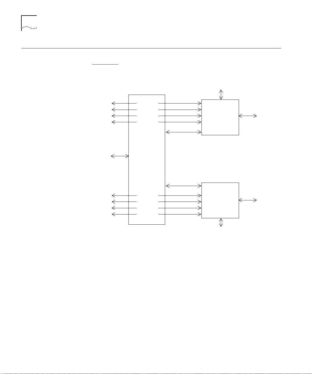
Carrier and Engine Architecture
This section provides an overview of the carrier and engine architecture.
Figure 1-1
Backplane
network
conne cti ons
Carrier
management
interface
Backplane
network
connections
is an architectural block diagram.
Engine management
interface
Port 1
Port 2
Port 3
Port 4
Control
interface
CARRIER
Control
interface
Port 5
Port 6
Port 7
Port 8
ENGINE 1
ENGINE 2
Devices
Devices
Figure 1-1 Carrier and Engine Architecture
Engi ne management
interface
Page 17

Carrier and Engine Architecture 1-3
The following list summarizes important features of the carrier and
engine architecture:
■ The carrier provides four internal ports for use by each engine.
These ports independently connect to backplane networks on the
hub. Some engines may not use all four ports.
■ You manage the engine through the engine management interface,
which is accessible through a serial connector on the front panel of
the engine. You can also use in-band management if the engine
supports it. For details on the engine management interface, refer to
the documentation for the engine.
■ You manage the carrier through the command interface provided by
the 3Com CoreBuilder 5000 Distributed Management Module
(DMM) installed in the hub.
■ The control interface between the carrier and the engine provides
internal timing and low-level control functions. These functions are
not user-accessible.
Page 18

Page 19

2
INSTALLATION
This chapter describes the installation of the CoreBuilder™ 5000
Ethernet Carrier. It contains the following sections:
■ Precautionary Procedures
■ Unpacking Procedures
■ Assembling the Module
■ Setting the Carrier DIP Switches
■ Setting the Carrier Jumpers
■ Installing the Module in a CoreBuilder 5000 Hub
Precautionary Procedures
Electrostatic discharge (ESD) can damage static-sensitive devices on
circuit boards. Observe the following precautions when you handle the
carrier:
CAUTION: Do not remove the board from its antistatic shielding bag
until you are ready to inspect or install it.
Handle the board by the faceplate only.
Use one of the following proper grounding techniques whenever you
handle the carrier:
■ Use a foot strap and grounded mat or wear a grounded static
discharge wrist strap.
■ Touch the grounded rack or other source of ground just before you
handle the carrier.
Page 20

2-2 INSTALLATION
Unpacking Procedures
To unpack the CoreBuilder 5000 Ethernet Carrier:
1 Verify that you received the correct model by checking the model
number listed on the side of the shipping carton.
Note that the product model number printed on the shipping box
differs from the model number on the product. The model number on
the shipping box contains the prefix ’3C9’.
2 Remove the carrier, in its antistatic wrapping, from the shipping carton.
3 Remove the carrier from the antistatic wrapping and inspect for
damage.
Handle the carrier by the faceplate only, being careful not to touch the
circuitry. If the carrier appears to be damaged, return it to the antistatic
wrapping, repack it in the shipping carton, and contact your local
supplier.
4 Verify that the contents of the shipment are complete:
■ CoreBuilder 5000 Ethernet Carrier (one or two engines may
already be mounted on the carrier)
■ CoreBuilder 5000 Ethernet Carrier Assembly and Configuration
Guide
■ Release notes, if applicable
5 Store the shipping carton and antistatic wrapping so that you can
repackage the carrier for storage or shipment.
Page 21

Assembling the Module
Assembling the Module 2-3
Your supplier may deliver the engine and carrier fully assembled.
If so, skip this section and go to Setting the Carrier DIP Switches on
page 2-9.
This section describes how to assemble the module by mounting the
engine on the CoreBuilder 5000 Ethernet Carrier. This section contains
the following sections:
■ Special Engine Requirements
■ Assembling the Module
Special Engine
Requirements
Some engines may have unique assembly requirements. Before
attempting to assemble the module, consult the documentation for
the engine.
Page 22
2-4 INSTALLATION
Assembling the
Module
CAUTION: Observe antistatic precautions as described in Precautionary
Procedures on page 2-1.
To assemble the module:
1 Select the engine bay in which you plan to install the engine
(Figure 2-1
).
You must use engine bay 1 if it is unoccupied. Use engine bay 2 only if
an engine is already installed in engine bay 1.
Engine bay 1
Engine bay 2
Figure 2-1 CoreBuilder 5000 Carrier Engine Bays
Page 23

Assembling the Module 2-5
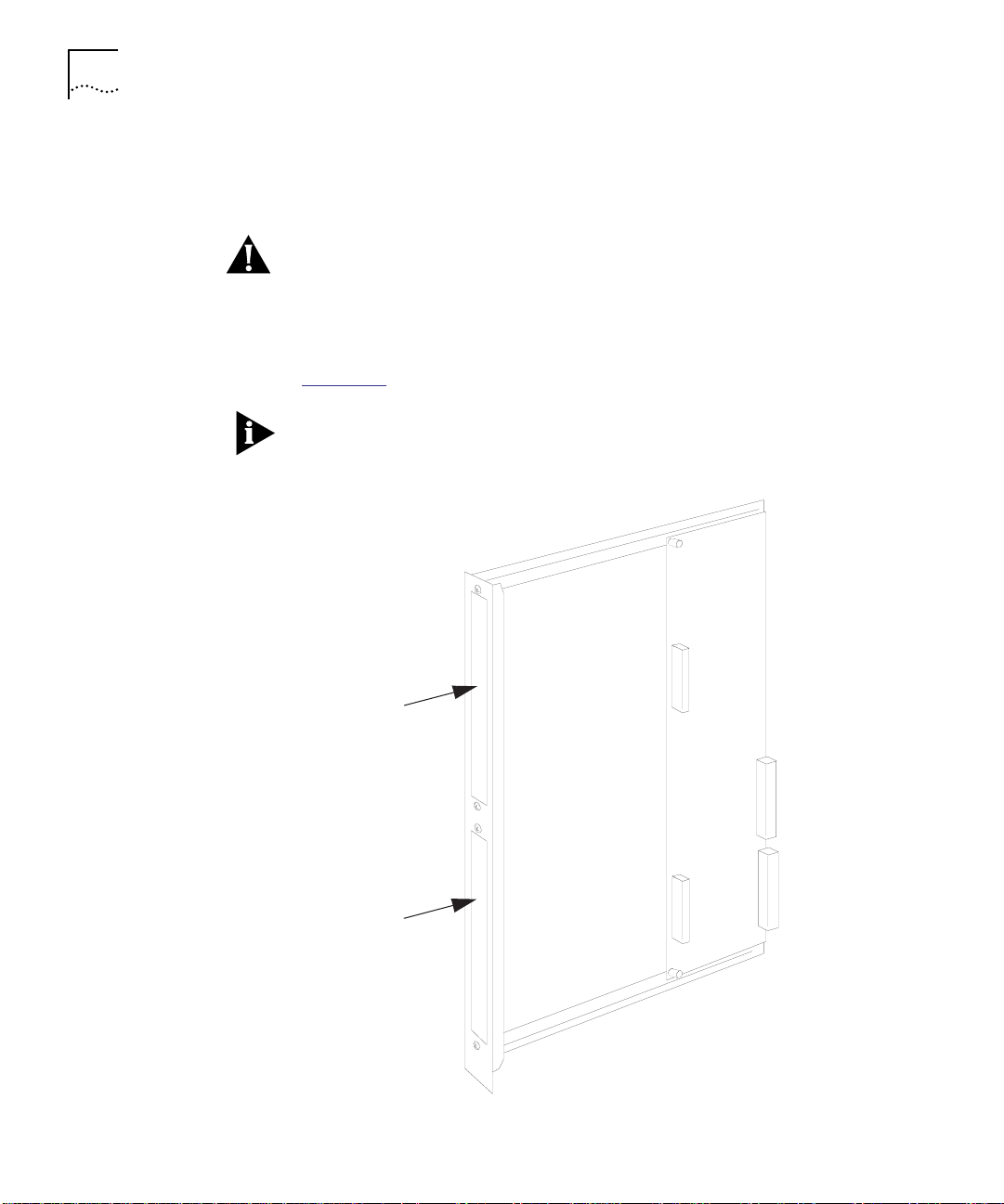
2 If you are installing an engine in engine bay 2, remove the two screws
that hold the blank faceplate in place (Figure 2-2
). Set the blank
faceplate and screws aside.
Screw
Blank faceplate
Screw
Figure 2-2 Blank Faceplate in Engine Bay 2
Page 24

2-6 INSTALLATION
3 Position the engine so that:
■ The interface connector on the engine inserts into the interface
connector on the carrier (Figure 2-3
■ The engine faceplate slides into place behind the carrier faceplate
(Figure 2-4
).
).
Slide the engine faceplate into place first, and then mate the
connectors.
Interface
connector
Interface
connector
Engine
Interface
connector
CoreBuilder 5000
carrier
Figure 2-3 Interface Connectors for CoreBuilder 5000 Carrier and Engine
Page 25

Carrier facepl ate
Engine faceplate
Assembling the Module 2-7
Figure 2-4 Faceplates for CoreBuilder 5000 Carrier and Engine
Page 26

2-8 INSTALLATION
4 As shown in Figure 2-5, use four screws and washers to fasten the
engine to:
■ The carrier standoffs (use the two screws and washers shipped
installed in the standoffs)
■ The carrier faceplate (use the two screws and washers packaged
with the engine)
Stando ff
Washer
Screw
Figure 2-5 Fastening the Engine to the CoreBuilder 5000 Carrier
Page 27

Setting the Carrier DIP Switches 2-9
If you are installing a second engine or an expansion card in the carrier,
first insert the outer front corner of the engine and then rotate the
inner front corner into place (Figure 2-6
). You must do this so that the
engine clears the ejector.
Ejector
Rotate en gine
in this direction
Setting the Carrier DIP Switches
Outer front corner of
engine
Figure 2-6 Installing a Second Engine
This section contains the following sections:
■ CoreBuilder 5000 Carrier DIP Switch Functions
■ Identifying the CoreBuilder 5000 Carrier DIP Switches
■ Enabling or Disabling NVRAM Configuration Settings
■ Assigning Backplane Networks to Carrier Ports
If you use a management module to manage your CoreBuilder 5000
hub, refer to Carrier Configuration Source Overview on page 3-2 before
setting the DIP switches.
Page 28

2-10 INSTALLATION
CoreBuilder 5000
Carrier DIP Switch
Functions
Identifying the
CoreBuilder 5000
Carrier DIP Switches
CoreBuilder 5000 Carrier DIP switches let you configure the following
functions:
■ NVRAM configuration settings
■ Backplane network assignments for carrier ports
Figure 2-7
locates and designates the CoreBuilder 5000 Carrier DIP
switches.
ONOFF
0
1
2
3
4
5
6
7
8
9
ENG 1
ENG 2
CH SEL 0
CH SEL 1
CH SEL 2
CH SEL 3
NV SEL
CH SEL 0
CH SEL 1
CH SEL 2
CH SEL 3
NV SEL
Figure 2-7 CoreBuilder 5000 Carrier DIP Switch Location
Page 29

Setting the Carrier DIP Switches 2-11
Enabling or
Disabling NVRAM
Configuration
Settings
Two NVRAM (labeled NV SEL) DIP switches control whether the
CoreBuilder 5000 Carrier uses configuration settings stored in NVRAM
(non-volatile memory) or DIP switches. Switch 4 provides the selection
for engine bay 1 and switch 9 provides the selection for engine bay 2.
In an unmanaged hub (a hub without a Distributed Management
Module (DMM) installed), the NVRAM DIP switch works as described in
Table 2-1
Table 2-1 NVRAM DIP Switch Settings (Unmanaged Hub)
NVRAM DIP
Switch
ON (enabled) The carrier uses configuration settings stored in its NVRAM. If
OFF (disabled) The carrier uses its DIP switch configuration settings.
.
Description
NVRAM does not contain settings, the carrier uses the following
configuration settings:
■ Ports 1 and 5 are assigned to the Isolated_1 network.
■ Ports 2 and 6 are assigned to the Isolated_2 network.
■ Ports 3 and 7 are assigned to the Isolated_3 network.
■ Ports 4 and 8 are assigned to the Isolated_4 network.
For instructions on using the NVRAM DIP switch in a managed hub
(DMM installed), refer to Carrier Configuration Source Overview on
page 3-2.
Assigning Backplane
Networks to Carrier
Ports
If the carrier is configured to use DIP switch settings, the network
selection DIP switch settings determine the backplane network
assignment for each port.
For information on configuring the carrier to use DIP switch settings:
■ In an unmanaged hub (no DMM installed), refer to Enabling or
Disabling NVRAM Configuration Settings on page 2-11.
■ In a managed hub (DMM installed), refer to Carrier Configuration
Source Overview on page 3-2.
Page 30

2-12 INSTALLATION
To select a network using DIP switches:
1 Set the switches according to Table 2-2
.
Table 2-2 Network Selection DIP Switch Settings
Network
Selection
Ethernet_1
(default)
Ethernet_2 OFF ON ON ON
Ethernet_3 ON OFF ON ON
Ethernet_4 OFF OFF ON ON
Ethernet_5 ON ON OFF ON
Ethernet_6 OFF ON OFF ON
Ethernet_7 ON OFF OFF ON
Ethernet_8 OFF OFF OFF ON
Isolate_1 ON ON ON OFF
Isolate_2 OFF ON ON OFF
Isolate_3 ON OFF ON OFF
Isolate_4 OFF OFF ON OFF
Switch combinations not listed in the Table 2-2
Switch Settings
CH SEL 0 CH SEL 1 CH SEL 2 CH SEL 3
ON ON ON ON
select Isolate_1.
Setting the Carrier Jumpers
This section describes how to use the CoreBuilder 5000 Carrier
jumpers. It contains the following sections:
■ Identifying the CoreBuilder 5000 Carrier DIP Switches
■ CoreBuilder 5000 Carrier Jumper Definitions
■ Disabling the Fast Reset Function
Page 31

Setting the Carrier Jumpers 2-13
Identifying the
CoreBuilder 5000
Carrier Jumpers
CoreBuilder 5000
Carrier Jumper
Definitions
Figure 2-8
locates and identifies the CoreBuilder 5000 Carrier jumpers.
ENG 1
FAST DIS
ENG 2
FAST DIS
P3
P4
Figure 2-8 CoreBuilder 5000 Carrier Jumpers
The CoreBuilder 5000 Carrier uses 2-pin jumpers, which can be
inserted or not inserted (Figure 2-9
).
Jumper pin
Not inserted (default)Inserted
Jumper
connector
Figure 2-9 Setting CoreBuilder 5000 Carrier Jumpers
Table 2-3 defines the CoreBuilder 5000 Carrier jumper settings.
Table 2-3 CoreBuilder 5000 Carrier Jumper Settings
Jumper Inserted Not Inserted
P3 (ENG 1 FAST DIS) Fast Reset disabled for
engine bay 1
P4 (ENG 2 FAST DIS) Fast Reset disabled for
engine bay 2
Fast Reset enabled for
engine bay 1 (default)
Fast Reset enabled for
engine bay 2 (default)
Page 32

2-14 INSTALLATION
Disabling the Fast
Reset Function
Installing the Module in a CoreBuilder 5000 Hub
The Fast Reset function restores clock synchronization to the engines if
a controller switchover occurs in the CoreBuilder 5000 hub.
■ If the engine supports Fast Reset, do not change the jumpers from
their default settings.
■ If the engine does not support Fast Reset, disable it. Disabling Fast
Reset causes a normal engine reset to occur during a controller
switchover.
To disable Fast Reset, insert the appropriate jumper (see Table 2-3
)
on the CoreBuilder 5000 Carrier.
You do not need to power down the CoreBuilder 5000 hub to install
or remove the module. You can insert the module while the hub is
operating (this is called a hot swap).
To install the module:
1 Use one of the following proper grounding techniques when you install
the module:
■ Properly ground yourself prior to handling the module.
■ Attach a static wrist guard to yourself or touch a grounded static
mat prior to handling the module.
2 To determine if the hub has enough power for the new module, enter
the SHOW POWER BUDGET command. Refer to Appendix A
for details
on power requirements for each of the specified wattages. For engine
power requirements, refer to the documentation for the engine.
Refer to the CoreBuilder 5000 Distributed Management Module
Commands Guide for information on the SHOW POWER BUDGET
command.
3 Locate an open slot in the hub. If necessary, remove a blank panel to
expose a slot.
Page 33

Installing the Module in a CoreBuilder 5000 Hub 2-15
4 Insert the module into the board guides at the top and bottom of the
slot and slide it into the hub by pressing firmly at a point slightly below
the center of the faceplate (Figure 2-10
).
Figure 2-10 Installing a CoreBuilder 5000 Module
Page 34

2-16 INSTALLATION
5 Close the ejectors (Figure 2-11).
Opened
ejector
Closed
eject or
Figure 2-11 Opened and Closed Module Ejectors
6 Using your fingers, tighten the spring-loaded screws on the front of the
carrier faceplate (do not overtighten).
Page 35

3
CONFIGURATION
This chapter describes how to configure the CoreBuilder 5000 Ethernet
Carrier. It contains the following sections:
■ Configuration Overview
■ Carrier Configuration Source Overview
■ Configuring the Carrier
■ Resetting the Carrier and Engines
To manage the engine, you must use engine management software.
For more information, refer to the documentation for the engine.
Configuration Overview
3Com Management
Agents
Using DIP Switch
and Jumper Settings
This section describes 3Com management agents and methods for
configuring the carrier. It contains the following sections:
■ 3Com Management Agents
■ Using DIP Switch and Jumper Settings
■ Using Management Commands
■ Using the 3Com CoreBuilder 5000 Manager
You can manage the carrier through SNMP (Simple Network
Management Protocol) or management commands if a local
management agent is available. Management agent services for the
carrier are provided by a 3Com CoreBuilder 5000 Distributed
Management Module (DMM) installed in the same hub as the carrier.
You can use DIP switches and jumpers on the carrier to perform certain
configuration functions. For information on using DIP switches and
jumpers, refer to Chapter 2
.
Page 36

3-2 CONFIGURATION
Using Management
Commands
Using the 3Com
CoreBuilder 5000
Manager
Carrier Configuration Source Overview
In this chapter, the section Configuring the Carrier on page 3-5
describes how to use management commands to make basic changes
to carrier configuration settings. For complete instructions on using
management commands to manage the carrier, refer to one of the
following:
■ CoreBuilder 5000 Distributed Management Module User Guide
(Document Number 17-00370)
■ CoreBuilder 5000 Management Module Commands Guide
(Document Number 17-00372)
The 3Com CoreBuilder 5000 Manager is an SNMP manager with a
graphical user interface. For instructions on using the CoreBuilder 5000
Manager to manage the carrier, refer to the CoreBuilder 5000 Manager
for UNIX User Guide (Document Number 17-00320).
This section describes the possible sources of carrier configuration
settings and the factors that determine which configuration source the
carrier uses. This section contains the following sections:
■ Carrier Configuration Sources
■ Hot-Swap Installation
Carrier
Configuration
Sources
■ Determining the Carrier Configuration Source
In a managed hub (hub with a DMM installed), the carrier obtains its
configuration settings from one of the following sources:
■ DMM settings
■ Carrier NVRAM settings
■ Carrier DIP switch settings
■ Carrier default settings
DMM Settings
The DMM can provide configuration settings to the carrier if you are
performing a hot-swap. For more information on hot-swapping, refer
to Hot-Swap Installation on page 3-4.
Page 37

Carrier Configuration Source Overview 3-3
Carrier NVRAM Settings
The carrier can store configuration settings in its NVRAM (Non-Volatile
Random Access Memory), which it can use when powering up in either
a managed or unmanaged hub. Two NVRAM DIP switches control
whether or not the carrier uses NVRAM settings. When the carrier is
shipped from the factory, its NVRAM contains no settings.
The carrier stores settings in NVRAM when either of the following
occurs:
■ You use a DMM configuration command or an SNMP manager to
change a carrier configuration setting. For example, if you use the
SET PORT NETWORK command to change a carrier port network
assignment, the carrier stores the new network assignment in its
NVRAM.
The carrier stores the new setting as soon as you issue the
command. The SAVE command does not affect the contents of
NVRAM.
■ The DMM sends settings to the carrier during a hot-swap. For a
definition of hot-swap, refer to Hot-Swap Installation on page 3-4.
For information on setting the NVRAM DIP switches, refer to Enabling
or Disabling NVRAM Configuration Settings on page 2-11.
Carrier DIP Switch Settings
The carrier contains a DIP switch that you can use to configure port
network assignments. For more information on DIP switch settings,
refer to Setting the Carrier DIP Switches on page 2-9.
Carrier Default Settings
In some cases the carrier uses default configuration settings contained
in its software. The carrier contains the following default settings for
port network assignment:
■ Ports 1 and 5 use Isolated_1
■ Ports 2 and 6 use Isolated_2
■ Ports 3 and 7 use Isolated_3
■ Ports 4 and 8 use Isolated_4
Page 38

3-4 CONFIGURATION
Hot-Swap Installation Whether or not you hot-swap the carrier affects which configuration
source the carrier uses.
Removing a carrier from the hub and installing an identical model
carrier in the same slot is a hot-swap. When you perform a hot-swap,
the DMM teaches the new carrier the configuration used by the old
carrier. The new carrier saves the settings in its NVRAM.
The DMM teaches the new carrier only if it has a saved configuration
for the old carrier installed in that slot. The DMM saves the
configuration when you do one of the following:
■ Issue the SAVE command.
■ Use SNMP to make the configuration changes to the carrier. The
DMM automatically saves the changes.
■ Reset or power-cycle the DMM. The DMM automatically learns and
saves the NVRAM configurations of all installed modules.
Swapping in a new carrier that contains a different engine from the old
carrier is still a hot-swap. Only the carrier models must be the same.
Page 39

Configuring the Carrier 3-5
Determining the
Carrier
Configuration Source
Table 3-1
shows how to determine the carrier configuration source.
Table 3-1 Determining the Carrier Configuration Source
Hot-swap?
DMM DIP
configuration
NVRAM DIP
*
Switch
Carrier
Configuration Source
Yes Disable ON or OFF DMM teaches the old
carrier configuration
settings to the new carrier.
Enable ON NVRAM settings
†
OFF DIP switch settings
No
‡
Disable ON NVRAM settings
2
OFF Default settings
Enable ON NVRAM settings
2
OFF DIP switch settings
* Use the SHOW DEVICE command to view the DIP configuration setting. Use the SET DEVICE
DIP_CONFIGURATION command to change the DIP configuration setting.
† If there are no settings stored in carrier NVRAM, the carrier uses default settings.
If the DMM detects a problem with the NVRAM configuration, it forces the carrier to use
default settings. For example, if you install the carrier with ports assigned to Ethernet_8 into
a CoreBuilder 5000 hub model that does not support Ethernet_8, the DMM forces the
carrier to use default settings. If the configuration problem is port-level, the DMM forces
only the affected ports to use default settings.
‡ The DMM must be fully initialized when you install the carrier module.
Configuring the Carrier
This section describes how to configure the carrier using network
management commands. It contains the following sections:
■ Selecting a Network
■ Saving the Configuration
■ Showing Carrier Configuration and Status
Selecting a Network The engine connects to the backplane through backplane ports on the
carrier. The carrier provides a total of eight backplane ports. Engine 1
uses ports 1 to 4 and Engine 2 uses ports 5 to 8. Depending on the
engine architecture, the engine may not use all of the ports.
Page 40

3-6 CONFIGURATION
You can assign a carrier module port to:
■ One of eight Ethernet backplane networks
■ One of four Isolated backplane networks
For details on backplane networks, refer to the CoreBuilder 5000
Integrated System Hub Installation and Operation Guide.
To assign the carrier module ports to a network using the network
management software, use the following command:
Saving the
Configuration
Showing Carrier
Configuration and
Status
SET PORT {
slot.port
} NETWORK {ethernet_1 ... ethernet_8}
{isolated_1 ... isolated_4}
For example, the following command sets port 1 in the carrier installed
in slot 3 to ethernet_2:
CB50 00> set po rt 3.1 network eth ernet_2
Port 03 .01 networ k id set to E THERNET_2
To save configuration changes, use the SAVE command. For example,
the following command saves all configuration changes:
CB50 00> save all
Failure to save module settings may result in the loss of configuration
data.
Use the following commands to show carrier configuration and status:
■ SHOW MODULE
■ SHOW PORT
Using the SHOW MODULE Command
The SHOW MODULE command displays information about a particular
module.
The syntax for the SHOW MODULE command is:
SHOW MODULE {
slot .sub sl ot
{all} {no_v er bo se}
} { ve rbos e}
Page 41

Configuring the Carrier 3-7
The following command uses the verbose option to display detailed
information on the carrier installed in slot 3:
CB50 00> show m odule 3.al l verbose
Slot Module Version Networ k General Inform ation
----- - --------- ----- ----- -- ------- ------ -- ----------- ------
03.01 6102M -SDEK 1. 00 PER_PORT 2109 R-RA
6102M-SDEK: CB5000 ON deck Ethe rnet Carr ier Module
Boot Versio n: 1.00
ENGINE 1 Mod el Number: 2109R-RA
Descri ption: LAN Acc ess
Expans ion Module Model Num ber:
Software Version: v5.04
Boot Versio n: v3.91
IP Defa ult Gatewa y: 155.10 2.2.1
Mailbo x Version: 1.00
No. Bac kplane Ports: 1
No. Fro nt Ports: 8
Engine Status: OK
NVRAM D ip Switch State: ENABLE D
Module Capabilit ies IPCFG;
ENGINE 2 Mod el Number: NOT INS TALLED
Description:
Expansion Module Model Number:
Software Version:
Boot Version:
IP Default G ateway: 0.0.0.0
Mailbox Ver sion: 0.00.0
No. Bac kplane Ports: 4
No. Fro nt Ports: 0
Engine Status: NOT INS TALLED
NVRAM D ip Switch State: DISABL ED
Module Capabilit ies NONE
If an output field is not applicable, it is left blank. In the example
above, no engine is installed in engine bay 2. Therefore, several fields
are blank in the section that describes engine 2.
Page 42

3-8 CONFIGURATION
Module Capabilities Field
The Module Capabilities field in the SHOW MODULE command output
contains a list of module capability codes. The codes describe optional
module capabilities that the installed engine supports. Module
capabilities are interactions that can occur through the interface
between the engine and the carrier.
Module capability codes indicate engine capabilities only.
Corresponding carrier management functions may not be available.
Also, module capability codes do not indicate engine functions that
are available through the engine management interface.
Table 3-2
Table 3-2 Module Capability Codes
Code Capability Description
ADSTAT Administrative State
IPCFG IP Configuration
MACCFG MAC Configuration
NETCFG Network Configuration
OPSTAT Operational Status
SANITY Heartbeat Check Engine supports echo requests and
SPDCFG Speed Configuration
defines the possible module capability codes.
Notification
Notification
Notification
Notification
Notification
Notification
Engine can report module and port
administrative states. Administrative
state refers to whether a module or
port is enabled or disabled.
Engine can report IP address changes.
Engine can report MAC address
changes.
Engine can accept notification of
backplane configuration changes.
Engine can report module and port
status information.
responses to support a heartbeat
mechanism.
Engine can accept notification of
speed changes.
Page 43

Configuring the Carrier 3-9
Engine Status Field
The Engine Status field in the SHOW MODULE command output
contains a value that describes current engine status. Table 3-3
describes the engine status values.
Table 3-3 Engine Status Values
Value Description
FATAL ERROR The engine reported a fatal error condition. Check
engine status using the engine management
interface.
INITIALIZING Carrier is waiting for installed engine to finish
initializing.
MAILBOX TIME-OUT A timeout failure occurred during communication on
the control interface between the carrier and engine.
Check engine status using the engine management
interface.
NOT INSTALLED No engine installed.
OKAY Engine has finished initializing and has communicated
its personality to the carrier.
TRANSIENT ERROR The engine reported a transient error condition.
Check engine status using the engine management
interface.
Using the SHOW PORT Command
The SHOW PORT command displays information on a single port or all
ports.
The syntax for the SHOW PORT command is:
SHOW PORT {
slot.port
{
slot
.all} {no_v erbose}
} {verbose}
Page 44

3-10 CONFIGURATION
CB50 00> show p ort 3.all verbose
Port Di splay for Module 6102M -SDEK :
Port Mode Status Netwo rk Gener al Inform ation
----- ------- ------------------- --------------- -------------------
03.01 L OGICAL OKAY ETHERNET_1 2109R -RA
Port Connec tor: BAC KPLANE
IP Addr ess: 155.1 04.15.40
Subnetwork Mask: ff.ff.ff.00
Statio n Address: 00- c0-2c-ff-fb-00
Dip Net work Setti ng: ETHERNE T_1
The following command displays information for port 1 on the carrier
installed in slot 3:
The command does not display data for unused ports. In the example
above, the engine uses only one of the four available backplane ports.
Therefore, the command displays information for one port only.
Resetting the Carrier and Engines
Using the Front Panel
Reset Switches
You can reset the carrier and installed engines using either of the
following methods:
■ Front panel reset switches
■ RESET MODULE command
To reset the carrier and installed engines, you can use the reset switch
provided on the engine faceplate.
■ To reset a single engine, press the reset switch for that engine and
hold it in for less than 3 seconds.
■ To reset all installed engines and the carrier, press the reset switch
on the engine and hold it in for longer than 3 seconds. If two
engines are installed, you can use either reset switch.
Page 45

Resetting the Carrier and Engines 3-11
Using the RESET
MODULE Command
To reset the carrier and installed engines, you can use the RESET
MODULE command.
The syntax for the RESET MODULE command is:
RESET MODUL E {s
lot.
1} {engine_1}
{engine_2}
{all}
engine_1 – Resets engine 1 only.
engine_2 – Resets engine 2 only.
all – Resets the carrier and all installed engines.
For example, the following command resets the carrier and all engines:
CB50 00> reset module 3.1 all
Resett ing module 3.1: all
Page 46

Page 47

A
SPECIFICATIONS
This appendix lists specifications for the CoreBuilder™ 5000 Ethernet
Carrier. This appendix contains the following sections:
■ Electrical Specifications
■ Environmental Specifications
■ Mechanical Specifications
Specifications listed in this appendix do not account for installed
engines.
Electrical Specifications
Table A-1 Carrier Electrical Specifications
Power
Requirements
Fuse Requirements 1 A @ +2 V
4 mA @ +2 V
800 mA @ +5 V
22 mA @ –5 V
15 A @ +5 V
1 A @ –5 V
3 A @ +12 V
2 A @ –12 V
Page 48

A-2 SPECIFICATIONS
Environmental Specifications
Mechanical Specifications
Table A-2 Carrier Environmental Specifications
Operating
Temperature
Storage
Temperature
Humidity Less than 95%, noncondensing
BTUs/hr 14.1 BTUs/hr
Table A-3 Carrier Mechanical Specifications
Dimensions 1.0" W x 14.37" H x 10.275" L
Weight 1.0 lb.
0 to 50 °C (32 to 122 °F)
–10 to 66 °C (14 to 151 °F)
Page 49

B
TECHNICAL SUPPORT
3Com provides access to technical support information through a
variety of services. This appendix describes these services.
Information contained in this appendix is correct at time of publication.
For the very latest, access 3Com Corporation’s World Wide Web site as
described below.
This appendix describes:
■ Online Technical Services
■ Support From Your Network Supplier
■ Support From 3Com Corporation
■ Returning Products for Repair
■ Accessing the 3Com MIB
Online Technical Services
■ Contacting 3Com Technical Publications
3Com offers worldwide product support 24 hours a day, 7 days a
week, through the following online systems:
■ World Wide Web Site
■ 3Com Bulletin Board Service
■ 3ComFacts Automated Fax Service
■ 3ComForum on CompuServe Online Service
Page 50

B-2 TECHNICAL SUPPORT
World Wide Web Site Access the latest networking information on 3Com Corporation’s World
Wide Web site by entering our URL into your Internet browser:
http ://ww w. 3Com .c om/
This service features news and information about 3Com products,
customer service and support, 3Com Corporation’s latest news releases,
NetAge Magazine, and more.
3Com Bulletin Board
Service
3ComBBS contains patches, software, and drivers for all 3Com
products, as well as technical articles. This service is available through
modem or ISDN 24 hours a day, 7 days a week.
Access by Analog Modem
To reach the service by modem, set your modem to 8 data bits,
no parity, and 1 stop bit. Call the telephone number nearest you:
Country Data Rate Telephone Number
Australia up to 14400 bps 61 2 9955 2073
Brazil up to 14400 bps 55 11 547 9666
France up to 14400 bps 33 1 6986 6954
Germany up to 28800 bps 4989 62732 188
Hong Kong up to 14400 bps 852 2537 5608
Italy (fee required) up to 14400 bps 39 2 27300680
Japan up to 14400 bps 81 3 3345 7266
Mexico up to 28800 bps 52 5 520 7853
P. R. of China up to 14400 bps 86 10 684 92351
Singapore up to 14400 bps 65 534 5693
Taiwan up to 14400 bps 886 2 377 5840
U.K. up to 28800 bps 44 1442 438278
U.S.A. up to 28800 bps 1 408 980 8204
Access by Digital Modem
ISDN users can call 3ComBBS using a digital modem for fast access up
to 56 Kbps. To access 3ComBBS using ISDN, use the following number:
408 654 2703
Page 51

Online Technical Services B-3
3ComFacts
Automated Fax
Service
3Com Corporation’s interactive fax service, 3ComFacts
SM
, provides data
sheets, technical articles, diagrams, and troubleshooting instructions on
3Com products 24 hours a day, 7 days a week.
Call 3ComFacts using your Touch-Tone telephone using one of these
international access numbers:
Country Telephone Number
Hong Kong 852 2537 5610
U.K. 44 1442 278279
U.S.A. 1 408 727 7021
Local access numbers are available within the following countries:
Telephone
Country
Australia 1 800 123853 Netherlands 06 0228049
Belgium 0800 71279 Norway 800 11062
Denmark 800 17319 Portugal 0505 442 607
Finland 98 001 4444 Russia (Moscow only) 956 0815
France 05 90 81 58 Spain 900 964 445
Germany 0130 81 80 63 Sweden 020 792954
Italy 1678 99085 U.K. 0800 626403
Number
Country
Telephone
Number
3ComForum on
CompuServe Online
Service
3ComForum is a CompuServe-based service containing patches,
software, drivers, and technical articles about 3Com products, as well
as a messaging section for peer support. To use 3ComForum, you
need a CompuServe
®
account.
To use 3ComForum:
1 Log on to CompuServe.
2 Ty pe
go threecom
3 Press Return to view the 3ComForum main menu.
Page 52

B-4 TECHNICAL SUPPORT
Support From Your Network Supplier
If additional assistance is required, contact your network supplier.
Several suppliers are authorized 3Com service partners who are
qualified to provide a variety of services, including network planning,
installation, hardware maintenance, application training, and support
services.
If you contact your network supplier for assistance, have the following
information ready:
■ Diagnostic error messages
■ A list of system hardware and software, including revision levels
■ Details about recent configuration changes, if applicable
If you are unable to contact your network supplier, refer to the
following section on how to contact 3Com.
Page 53

Support From 3Com Corporation B-5
Support From 3Com Corporation
If you are unable to receive support from your network supplier,
technical support contracts are available from 3Com.
Contact your local 3Com sales office to locate your authorized service
provider using one of the following numbers:
Regional Sales Office Telephone Number Regional Sales Office Telephone Number
3Com Corporation
U.S.A.
3Com ANZA
East
West
3Com Asia Limited
China
Hong Kong
India
Indonesia
Korea
Malaysia
Singapore
Taiwan
Thailand
3Com Benelux B.V.
Belgium
Netherlands
3Com Canada
Calgary
Montreal
Ottawa
Toronto
Vancouver
3Com France
3Com GmbH
Austria
Czech and Slovak Republics
Germany
Hungary
Poland
Switzerland
800 NET 3Com or
1 408 764 5000
61 2 9937 5000
61 3 9866 8022
86 10 68492 568 (Beijing)
86 21 6374 0220 Ext 6115
(Shanghai)
852 2501 1111
91 11 644 3974
62 21 523 9181
82 2 319 4711
60 3 732 7910
65 538 9368
886 2 377 5850
662 231 8151 4
32 725 0202
31 30 6029700
403 265 3266
514 683 3266
613 566 7055
416 498 3266
604 434 3266
33 1 69 86 68 00
43 1 5134323
42 2 21845 800
49 30 3498790 (Berlin)
49 89 627320 (Munich)
36 1 250 83 41
48 22 6451351
41 31 996 14 14
3Com Ireland
3Com Japan
3Com Latin America
Argentina
Brazil
Chile
Colombia
Mexico
Peru
Venezuela
3Com Mediterraneo
Italy
3Com Middle East
3Com Nordic AB
Denmark
Finland
Norway
Sweden
3Com Russia
3Com South Africa
3Com UK Limited
353 1 820 7077
81 3 3345 7251
54 1 312 3266
55 11 546 0869
56 2 633 9242
57 1 629 4110
52 5 520 7841
51 1 221 5399
58 2 953 8122
39 2 253011 (Milan)
39 6 5279941 (Rome)
971 4 349049
45 39 27 85 00
358 0 435 420 67
47 22 18 40 03
46 8 632 56 00
007 095 2580940
27 11 807 4397
44 131 2478558 (Edinburgh)
44 161 8737717 (Manchester)
44 1628 897000 (Marlow)
Page 54

B-6 TECHNICAL SUPPORT
Returning Products for Repair
Accessing the
3Com MIB
Before you send a product directly to 3Com for repair, you must first
obtain a Return Materials Authorization (RMA) number. Products sent
to 3Com without RMA numbers are returned to the sender unopened,
at the sender’s expense.
To obtain an RMA number, call or fax:
Country Telephone Number Fax Number
U.S.A. and Canada 1 800 876 3266, option 2 408 764 7120
Latin America 1 408 326 7801 408 764 7120
Europe, South Africa and
Middle East
Outside Europe, U.S.A.,
and Canada
44 1442 438125 44 1442 435822
1 408 326 7804 1 408 764 7120
The 3Com Management Information Base (MIB) describes commands
that enable you to manage 3Com SNMP-based products. The MIB is
available over the Internet on an anonymous FTP server. Updates to
these MIBs are released as new 3Com products are introduced.
To access Internet versions:
1 FTP to
ftp.3com.com (151.104.9.65).
2 Enter the login name anonymous .
3 Enter your full Internet e-mail address as the password
(for example,
4 Change to the /pub/mibs directory using the command
jdoe@company.com).
cd/pub/mibs.
5 Read the readisd.txt file to determine the MIB or MIBs you need to
manage your 3Com products.
6 To view the 3Com MIB, OID, or schema entries, enter the
■ To pause the display, press Ctrl+S.
■ To continue the display, press Ctrl+Q.
ls command.
7 Copy the MIB, OID, or schema files to your current directory using the
appropriate command (for example,
8 Exit the FTP session using the
quit command.
get isd.mib).
Page 55

Contacting 3Com Technical Publications B-7
Contacting 3Com Technical Publications
02/06/97
If you have comments or questions on 3Com Technical Publications
documents, contact the Technical Publications group by fax at
(508) 229-1551.
Page 56

Page 57

INDEX
Numerics
3Com Bulletin Board Service (3ComBBS) B-2
3Com sales offices B-5
3Com URL B-2
3ComFacts B-3
3ComForum B-3
A
Audience of Manual 1
B
bulletin board service B-2
C
CompuServe B-3
Contents, package 2-2
CoreBuilder 5000 Hub
hot swap capabilities
2-14
D
DIP Switch
setting
2-9
E
Edge Router Module
installing
Electrical specifications A-1
Electro-static discharge
precautionary procedures
Environmental specifications A-2
2-14
2-1
F
fax service. See 3ComFacts
FCC notice
ii
I
Installation
hot swap capabilities
installing the module 2-14 to 2-16
module 2-15, 2-16
2-14
M
Mechanical specifications A-2
Media module
procedures for handling
MIBs
3Com
B-6
2-1
Page 58

2 INDEX
N
Network Management Commands
Set Port Network
Network Selection 3-5
network supplier support B-4
3-6
O
Online technical services B-1
P
Package contents 2-2
R
returning products for repair B-6
S
Selecting a Network 3-6
using network management 3-6
Set Port Network Command 3-6
Shipment contents 2-2
Show Module Command 3-6
Show Port Command 3-9
Simple Network Management Protocol (SNMP)
commands
SNMP. See Simple Network Management Protocol
B-6
U
Unpacking Procedures 2-2
URL B-2
W
World Wide Web B-2
WWW B-2
T
technical support B-1
3Com URL B-2
bulletin board service B-2
fax service B-3
network suppliers B-4
product repair B-6
using CompuServe B-3
Page 59

3Com Corporation LIMITED WARRANTY
For purposes of this warranty, the CoreBuilder 5000 Ethernet Carrier is considered an Internetworking product.
HARDWARE 3Com warrants its hardware products to be free from defects in workmanship and materials, under
SOFTWARE 3Com warrants that the software programs licensed from it will perform in substantial conformance to the
normal use and service, for the following lengths of time from the date of purchase from 3Com or its
Authorized Reseller:
Internetworking products 1 year
Network adapters Lifetime
Ethernet stackable hubs and Unmanaged Ethernet fixed port repeaters Lifetime*
*Power supply and fans in the stackable hubs and unmanaged repeaters 1 year
Other hardware products 1 year
Spare parts and spares kits 90 days
If a product does not operate as warranted above during the applicable warranty period, 3Com shall, at
its option and expense, repair the defective product or part, deliver to Customer an equivalent product or
part to replace the defective item, or refund to Customer the purchase price paid for the defective
product. All products that are replaced will become the property of 3Com. Replacement products may be
new or reconditioned. Any replaced or repaired product or part has a 90-day warranty or the remainder of
the initial warranty period, whichever is longer.
3Com shall not be responsible for any software, firmware, information, or memory data of Customer
contained in, stored on, or integrated with any products returned to 3Com for repair, whether under
warranty or not.
program specifications therefor for a period of 90 days from the date of purchase from 3Com or its
Authorized Reseller. 3Com warrants the media containing software against failure during the warranty
period. No updates are provided. 3Com’s sole obligation with respect to this express warranty shall be (at
3Com’s discretion) to refund the purchase price paid by Customer for any defective software products, or
to replace any defective media with software which substantially conforms to 3Com’s applicable published
specifications. Customer assumes responsibility for the selection of the appropriate applications program
and associated reference materials. 3Com makes no warranty or representation that its software products
will work in combination with any hardware or applications software products provided by third parties,
that the operation of the software products will be uninterrupted or error free, or that all defects in the
software products will be corrected. For any third-party products listed in the 3Com software product
documentation or specifications as being compatible, 3Com will make reasonable efforts to provide
compatibility, except where the noncompatibility is caused by a “bug” or defect in the third party’s
product.
(1 year if not registered)
STANDARD WARRANTY
S
ERVICE
WARRANTIES EXCLUSIVE IF A 3COM PRODUCT DOES NOT OPERATE AS WARRANTED ABOVE, CUSTOMER’S SOLE REMEDY FOR
Standard warranty service for hardware products may be obtained by delivering the defective product,
accompanied by a copy of the dated proof of purchase, to 3Com’s Corporate Service Center or to an
Authorized 3Com Service Center during the applicable warranty period. Standard warranty service for
software products may be obtained by telephoning 3Com’s Corporate Service Center or an Authorized
3Com Service Center, within the warranty period. Products returned to 3Com’s Corporate Service Center
must be pre-authorized by 3Com with a Return Material Authorization (RMA) number marked on the
outside of the package, and sent prepaid, insured, and packaged appropriately for safe shipment. The
repaired or replaced item will be shipped to Customer, at 3Com’s expense, not later than 30 days after
receipt of the defective product by 3Com.
BREACH OF THAT WARRANTY SHALL BE REPAIR, REPLACEMENT, OR REFUND OF THE PURCHASE PRICE
PAID, AT 3COM’S OPTION. TO THE FULL EXTENT ALLOWED BY LAW, THE FOREGOING WARRANTIES AND
REMEDIES ARE EXCLUSIVE AND ARE IN LIEU OF ALL OTHER WARRANTIES, TERMS, OR CONDITIONS,
EXPRESS OR IMPLIED, EITHER IN FACT OR BY OPERATION OF LAW, STATUTORY OR OTHERWISE,
INCLUDING WARRANTIES, TERMS, OR CONDITIONS OF MERCHANTABILITY, FITNESS FOR A PARTICULAR
PURPOSE, AND SATISFACTORY QUALITY. 3COM NEITHER ASSUMES NOR AUTHORIZES ANY OTHER
PERSON TO ASSUME FOR IT ANY OTHER LIABILITY IN CONNECTION WITH THE SALE, INSTALLATION,
MAINTENANCE, OR USE OF ITS PRODUCTS.
Page 60

3COM SHALL NOT BE LIABLE UNDER THIS WARRANTY IF ITS TESTING AND EXAMINATION DISCLOSE
THAT THE ALLEGED DEFECT IN THE PRODUCT DOES NOT EXIST OR WAS CAUSED BY CUSTOMER’S OR
ANY THIRD PERSON’S MISUSE, NEGLECT, IMPROPER INSTALLATION OR TESTING, UNAUTHORIZED
ATTEMPTS TO REPAIR OR MODIFY, OR ANY OTHER CAUSE BEYOND THE RANGE OF THE INTENDED USE,
OR BY ACCIDENT, FIRE, LIGHTNING, OR OTHER HAZARD.
LIMITATION OF LIABILITY TO THE FULL EXTENT ALLOWED BY LAW, 3COM ALSO EXCLUDES FOR ITSELF AND ITS SUPPLIERS ANY
LIABILITY, WHETHER BASED IN CONTRACT OR TORT (INCLUDING NEGLIGENCE), FOR INCIDENTAL,
CONSEQUENTIAL, INDIRECT, SPECIAL, OR PUNITIVE DAMAGES OF ANY KIND, OR FOR LOSS OF REVENUE
OR PROFITS, LOSS OF BUSINESS, LOSS OF INFORMATION OR DATA, OR OTHER FINANCIAL LOSS ARISING
OUT OF OR IN CONNECTION WITH THE SALE, INSTALLATION, MAINTENANCE, USE, PERFORMANCE,
FAILURE, OR INTERRUPTION OF ITS PRODUCTS, EVEN IF 3COM OR ITS AUTHORIZED RESELLER HAS BEEN
ADVISED OF THE POSSIBILITY OF SUCH DAMAGES, AND LIMITS ITS LIABILITY TO REPAIR, REPLACEMENT,
OR REFUND OF THE PURCHASE PRICE PAID, AT 3COM’S OPTION. THIS DISCLAIMER OF LIABILITY FOR
DAMAGES WILL NOT BE AFFECTED IF ANY REMEDY PROVIDED HEREIN SHALL FAIL OF ITS ESSENTIAL
PURPOSE.
Some countries, states, or provinces do not allow the exclusion or limitation of implied warranties or the
limitation of incidental or consequential damages for certain products supplied to consumers, so the above
limitations and exclusions may be limited in their application to you. This warranty gives you specific legal
rights which may vary depending on local law.
GOVERNING LAW This Limited Warranty shall be governed by the laws of the state of California.
3Com Corporation, 5400 Bayfront Plaza, Santa Clara, CA 95052-8145 (408) 764-5000
10/20/96
 Loading...