

Page 1

3Com® Switch 4500G Family
www.3Com.com
Part Number: 10014899 Rev. AC
Published: October 2007
Getting Started Guide
Switch 4500G 24-Port
Switch 4500G 48-Port
Switch 4500G PWR 24-Port
Switch 4500G PWR 48-Port
Page 2

3Com Corporation
350 Campus Drive
Marlborough, MA
USA 01752-3064
Copyright © 2006-2007, 3Com Corporation. All rights reserved. No part of this documentation may be
reproduced in any form or by any means or used to make any derivative work (such as translation,
transformation, or adaptation) without written permission from 3Com Corporation.
3Com Corporation reserves the right to revise this documentation and to make changes in content from
time to time without obligation on the part of 3Com Corporation to provide notification of such revision
or change.
3Com Corporation provides this documentation without warranty, term, or condition of any kind, either
implied or expressed, including, but not limited to, the implied warranties, terms or conditions of
merchantability, satisfactory quality, and fitness for a particular purpose. 3Com may make improvements
or changes in the product(s) and/or the program(s) described in this documentation at any time.
If there is any software on removable media described in this documentation, it is furnished under a
license agreement included with the product as a separate document, in the hard copy documentation,
or on the removable media in a directory file named LICENSE.TXT or !LICENSE.TXT. If you are unable to
locate a copy, please contact 3Com and a copy will be provided to you.
UNITED STATES GOVERNMENT LEGEND
If you are a United States government agency, then this documentation and the software described
herein are provided to you subject to the following:
All technical data and computer software are commercial in nature and developed solely at private
expense. Software is delivered as “Commercial Computer Software” as defined in DFARS 252.227-7014
(June 1995) or as a “commercial item” as defined in FAR
rights as are provided in 3Com’s standard commercial license for the Software. Technical data is
provided with limited rights only as provided in DFAR 252.227-7015 (Nov
1987), whichever is applicable. You agree not to remove or deface any portion of any legend provided
on any licensed program or documentation contained in, or delivered to you in conjunction with, this
User Guide.
Unless otherwise indicated, 3Com registered trademarks are registered in the United States and may or
may not be registered in other countries.
3Com and the 3Com logo are registered trademarks of 3Com Corporation.
Cisco is a registered trademark of Cisco Systems, Inc.
Funk RADIUS is a registered trademark of Funk Software, Inc.
Aegis is a registered trademark of Aegis Group PLC.
Intel and Pentium are registered trademarks of Intel Corporation. Microsoft, MS-DOS, Windows, and
Windows NT are registered trademarks of Microsoft
trademarks of Novell,
licensed exclusively through X/Open Company, Ltd.
IEEE and 802 are registered trademarks of the Institute of Electrical and Electronics Engineers, Inc.
All other company and product names may be trademarks of the respective companies with which they
are associated.
ENVIRONMENTAL STATEMENT
It is the policy of 3Com Corporation to be environmentally friendly in all operations. To uphold our
policy, we are committed to:
Establishing environmental performance standards that comply with national legislation and regulations.
Conserving energy, materials and natural resources in all operations.
Reducing the waste generated by all operations. Ensuring that all waste conforms to recognized
environmental standards. Maximizing the recyclable and reusable content of all products.
Ensuring that all products can be recycled, reused and disposed of safely.
Ensuring that all products are labelled according to recognized environmental standards.
Improving our environmental record on a continual basis.
End of Life Statement
3Com processes allow for the recovery, reclamation and safe disposal of all end-of-life electronic
components.
Regulated Materials Statement
3Com products do not contain any hazardous or ozone-depleting material.
Inc. UNIX is a registered trademark in the United States and other countries,
2.101(a) and as such is provided with only such
1995) or FAR 52.227-14 (June
Corporation. Novell and NetWare are registered
Page 3

CONTENTS
ABOUT THIS GUIDE
Before You Start 5
Conventions 6
Related Documentation 6
INTRODUCING THE SWITCH 4500G FAMILY
About the Switch 4500G 7
Switch 4500G 24-Port and 48-Port—Front and Rear Panel Detail 8
Switch 4500G 24-Port and 48-Port Front Panel LEDs 10
Switch 4500G PWR 24-Port and 48-Port —Front and Rear Panel Detail 13
Switch 4500G PWR 24-Port and 48-Port Front Panel LEDs 15
System Specifications of the Switch 4500G 18
INSTALLING THE SWITCH
Rack-Mounting the Switch 20
Mounting the Switch on a Desktop 23
The Power-up Sequence 23
Connecting a Redundant Power Supply 24
Connecting Console Cable 28
SETTING UP SWITCH MANAGEMENT
Methods of Managing a Switch 31
Setting Up Your Switch 33
Manually Configuring IP Information 36
Viewing Automatically Configured IP Information 42
Setting Up Command Line Interface Management 44
Setting Up Command Line Interface Management using SSH 45
Setting Up Web Interface Management 45
Setting Up SNMP Management V1 or V2 46
Default Users and Passwords 47
PROBLEM SOLVING
Solving Problems Indicated by LEDs 50
Solving Hardware Problems 51
Solving Communication Problems 52
Solving Fabric Formation Problems 53
Page 4

PIN-OUTS
Null Modem Cable 55
PC-AT Serial Cable 55
Modem Cable 56
Ethernet Port RJ-45 Pin Assignments 56
TECHNICAL SPECIFICATIONS
Switch 4500G 24-Port 59
Switch 4500G 48-Port 60
Switch 4500G PWR 24-Port 61
witch 4500G PWR 48-Port 62
Grounding Lead 63
OBTAINING SUPPORT FOR YOUR 3COM PRODUCTS
Register Your Product to Gain Service Benefits 65
Solve Problems Online 65
Purchase Extended Warranty and Professional Services 65
Access Software Downloads 66
Contact Us 66
3COM NETWORK MANAGEMENT
3Com Network Supervisor 69
3Com Network Director 70
3Com Network Access Manager 70
3Com Enterprise Management Suite 71
Integration Kit with HP OpenView Network Node Manager 71
REDUNDANT POWER SUPPLY SAFETY INFORMATION
Important Safety Information 73
L’information de Sécurité Importante 74
Wichtige Sicherheitsinformationen 75
Información de Seguridad Importante 76
Importanti Informazioni di Sicurezza 78
Wa¿ne informacje o zabezpieczeniach 79
Regulatory Notices 81
Page 5

ABOUT THIS GUIDE
Download the latest
software and
documentation for your
3Com switch
Thank you for purchasing a 3Com Switch 4500G. As part of our
commitment to bringing you the most capable and dependable
network equipment, 3Com offers free software maintenance
updates and documentation updates on our website.
To obtain the most up-to-date operating software and user
documentation for the Switch 4500G, point your web browser to:
www.3Com.com/4500G and select the “Support and
Registration” link.
Please note that you must register your 3Com switch to receive
software upgrades. To register, point your web browser to
eSupport.3Com.com.
Before You Start The guide is intended for use by network administrators who
install and set up network equipment; consequently, it assumes a
basic working knowledge of Local Area Networks (LANs).
Release Notes The Release Notes provide important information about the
current software release, including new features, modifications,
known problems, and instructions for upgrading your switch. You
should read the Release Notes before installing the switch in your
network.
If the information in the Release Notes differs from this guide,
follow the instructions in the Release Notes.
User documentation and release notes are available in Adobe
Acrobat Reader Portable Document Format (PDF) on the 3Com
Wide Web site at http://www.3com.com
World
Page 6
6 ABOUT THIS GUIDE
Conventions Ta bl e 1 lists important conventions that are used throughout this guide.
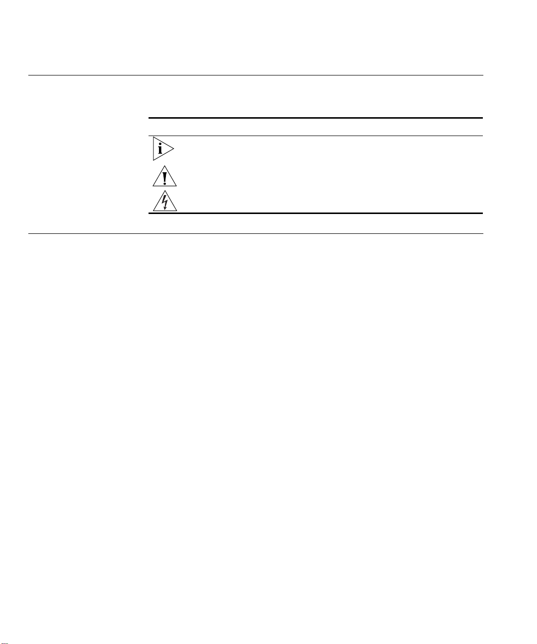
Table 1 Notice Icons
Icon Notice Type Description
Information note Information that describes important features or
Caution Information that alerts you to potential loss of data or
Warning Information that alerts you to potential personal injury
instructions
potential damage to an application, system, or device
Related Documentation
In addition to this guide, the Switch 4500G documentation includes the
following:
■ 3Com Switch 4500G Family Configuration Guide
This guide contains information on the features supported by your
switch and how they can be used to optimize your network. It is
supplied in PDF format on the 3Com Web site.
■ 3Com Switch 4500G Family Command Reference Guide
This guide provides detailed information about the web interface and
command line interface that enable you to manage the switch. It is
supplied in PDF format on the 3Com Web site.
■ 3Com Switch 4500G Family Quick Reference Guide
This guide contains:
■ a list of the features supported by the switch.
■ a summary of the command line interface commands for the switch.
This guide is also available under the Help button on the web
interface.
■ Release Notes
These notes provide information about the current software release,
including new features, modifications, and known problems. This
document also provides detailed instructions for upgrading your switch
with the latest software.
Page 7

INTRODUCING THE SWITCH 4500G
1
About the Switch 4500G
FAMILY
This chapter introduces the Switch 4500G and describes how it can be used in
your network. It includes a description of the hardware and software features and
covers the following topics:
■ About the Switch 4500G
■ Switch 4500G 24-Port and 48-Port—Front and Rear Panel Detail
■ Switch 4500G 24-Port and 48-Port Front Panel LEDs
■ Switch 4500G PWR 24-Port and 48-Port —Front and Rear Panel Detail
■ Switch 4500G PWR 24-Port and 48-Port Front Panel LEDs
■ System Specifications of the Switch 4500G
The 3Com® Switch 4500G (hereinafter referred to as Switch 4500G) are Gigabit
Ethernet switching products developed by 3Com. The 3Com® Switch 4500G
family delivers flexible quad-speed performance (10/100/1000 and 10-Gigabit)
and advanced voice-optimized features such as Power over Ethernet (PoE),
auto-QoS and auto-voice VLAN. This makes the Switch 4500G ideal for medium
businesses and small enterprises seeking to build a secure converged network.
Currently, the Switch 4500G includes the following models:
■ Switch 4500G 24-Port
■ Switch 4500G 48-Port
■ Switch 4500G PWR 24-Port
■ Switch 4500G PWR 48-Port
The Switch 4500G features the following advantages:
■ Providing full Gigabit speed access ports
■ Providing 10-Gigabit uplink ports
■ Supporting IPv4 hardware forwarding
■ Supporting jumbo frames
■ Supporting port security
■ Supporting link aggregation control protocol (LACP)
■ Supporting 256 VLANs
■ Supporting ACLs
■ Supporting port-based/flow-based mirroring
Page 8
8 CHAPTER 1: INTRODUCING THE SWITCH 4500G FAMILY
(6)
(7)
(8)
(9)
For information about using the software features of the Switch, refer to the
“Command Reference Guide” and the “Configuration Guide”.
Summary of Hardware
Features
Ta bl e 2 summarizes the hardware features that are supported by the Switch
4500G.
Table 2 Hardware Features
Feature Switch 4500G
Addresses Up to 8,000 supported
Auto-negotiation Supported on all ports
Forwarding Modes Store and Forward
Duplex Modes Half and full duplex on all front panel ports
Auto MDI/MDIX Supported on all ports. If fiber SFP transceivers are
Flow Control In full duplex operation all ports are supported.
Traffic Prioritization Supported (using the IEEE Std 802.ID, 1998 Edition):
Power over Ethernet Supported on all front panel ports (3CR17171-91 and
Ethernet, Fast Ethernet, and
Gigabit Ethernet Ports
SFP Ethernet Ports Supports fiber Gigabit Ethernet long-wave (LX),
Mounting 19-inch rack or standalone mounting
Clustering Up to 32 (0–31) units can be linked together
used, Auto MDIX is not supported.
The Switch 4500G ports can receive, but not send
pause frames.
Eight traffic queues per port
3CR17172-91only
Auto-negotiating 10/100/1000BASE-T ports or
100BASE-FX ports (3CR17181-91)
long-haul (LH70) and copper (T), 100BASE-LX10, and
100BASE-FX transceivers in any combination.
(31 members and 1 commander)
).
Switch 4500G 24-Port
and 48-Port—Front
and Rear Panel Detail
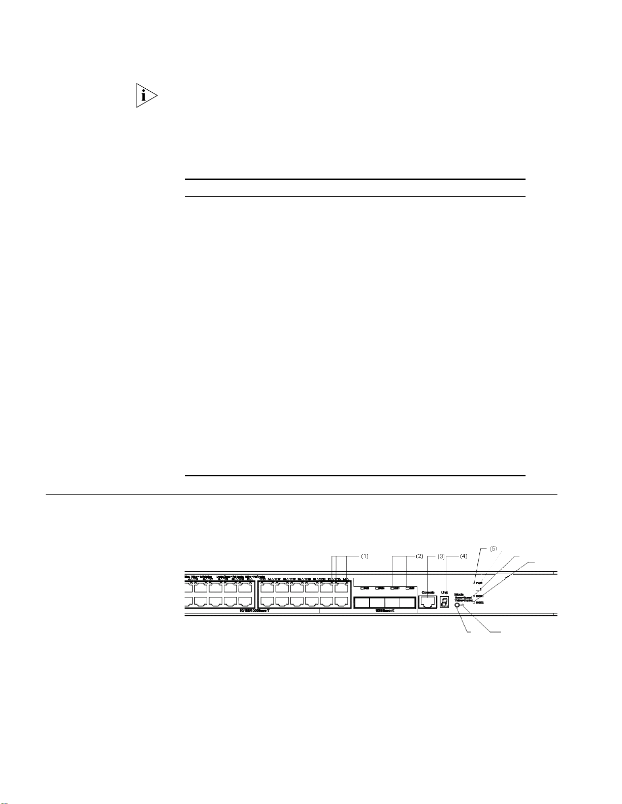
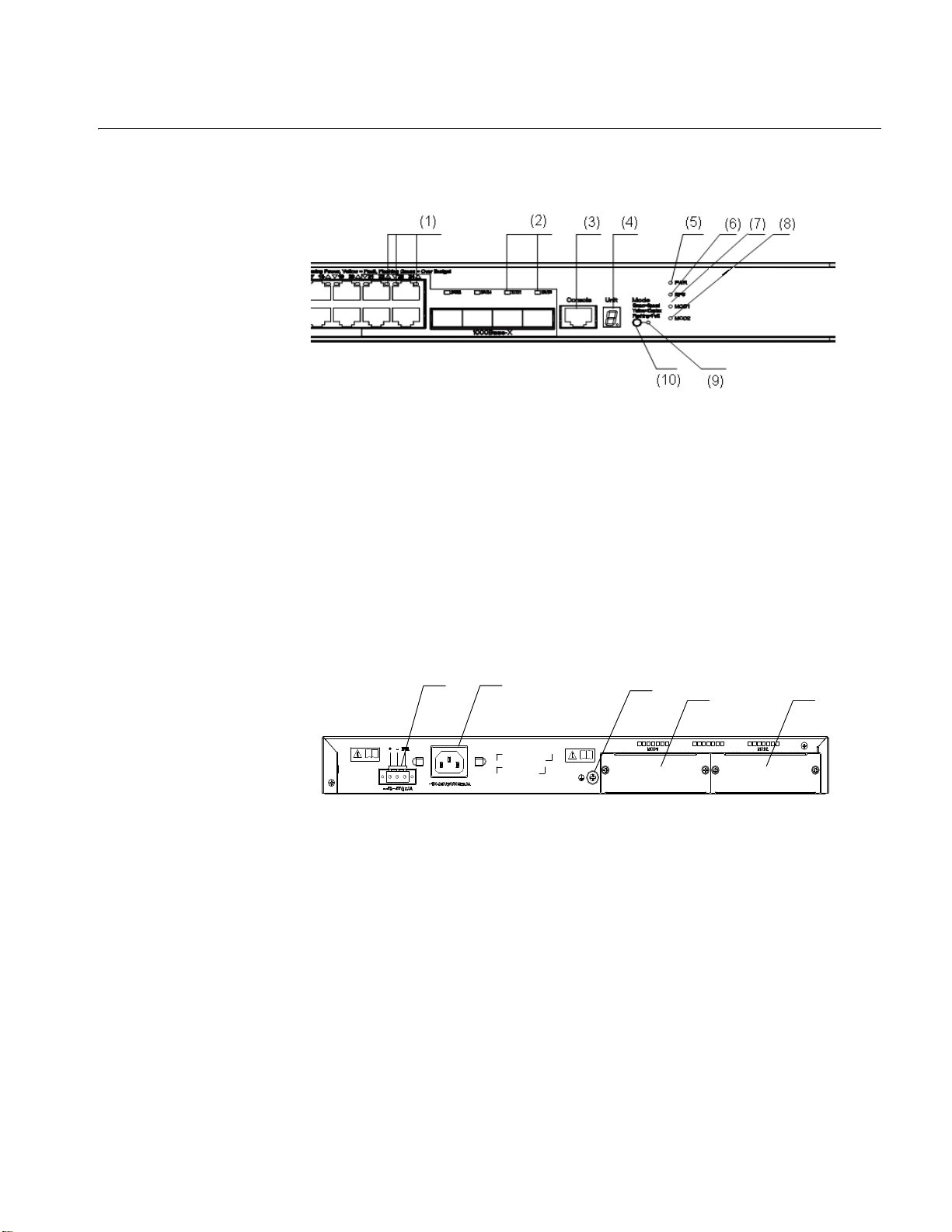
Figure 1 displays the front panel of the Switch 4500G 24-Port unit.
Figure 1 Switch 4500G 24-Port—front panel
(1) 10/100/1000 BASE-T autosensing
Ethernet port status LED
(3) Console port (4) 7-segment digitron display
(5) Power LED ((6) LED for extended slot 1
(8) LED for extended slot 2 (9) Mode LED
(10) Mode switching button
(2) Gigabit SFP Combo port status LED
Page 9
Switch 4500G 24-Port and 48-Port—Front and Rear Panel Detail 9
(1) (2)
(3)
(4)
(5)
(1) (2)
(3)
(4)
(5)
(2)
(3)
(4)
(7)
(8)
(9)
(1)
(2)
(3)
(4)
(5)
(1)
(2)
(3)
(4)
(5)
(2)
(3)
(4)
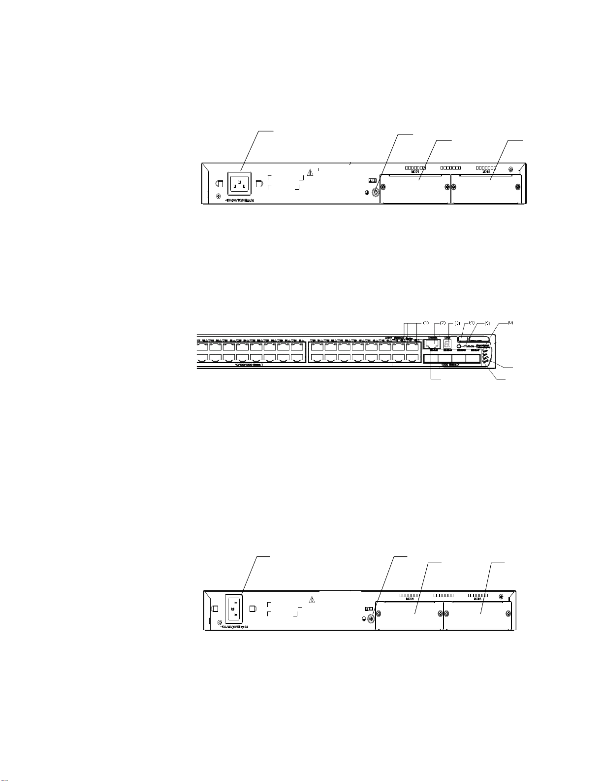
Figure 2 displays the rear panel of the Switch 4500G 24-Port unit.
Figure 2 Switch 4500G 24-Port—rear panel
(1) AC power input (2) Grounding terminal
(3) Extended slot 1 (4) Extended slot 2
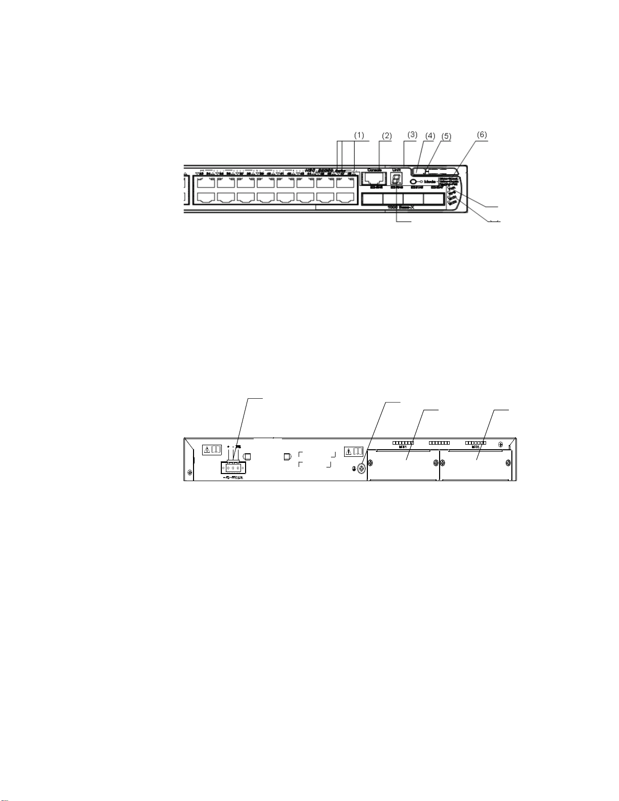
Figure 3 displays the front panel of the Switch 4500G 48-Port unit.
Figure 3 Switch 4500G 48-Port—front panel
(1) 10/100/1000 BASE-T autosensing
(2) Console port
Ethernet port status LED
(3) 7-segment digitron display (4) Mode switching button
(5) Mode LED (6) Power LED
(7) LED for extended slot 1 (8) LED for extended slot 2
(9) Gigabit SFP Combo port status LED
Figure 4 displays the rear panel of the Switch 4500G 48-Port unit.
Figure 4 Switch 4500G 48-Port—rear panel
(1) AC power input (2) Grounding terminal
(3) Extended slot 1 (4) Extended slot 2
Page 10

10 CHAPTER 1: INTRODUCING THE SWITCH 4500G FAMILY
Switch 4500G 24-Port and 48-Port Front Panel LEDs
The Switch 4500G 24-Port and 48-Port units provide LEDs on the front panel to
allow you to monitor the switch.
Ta bl e 3 describes these LEDs. You can use the
mode button on the front panel to switch the LEDs display mode (rate mode or
duplex mode).
Table 3 Switch 4500G 24-Port and 48-Port Front Panel LEDs
LED Label Status Description
Mode LED Mode Rate
Power LED PWR Green, ON The switch starts normally.
Module LED Module
(MOD)
mode
Duplex
mode
Green, blinking (1 Hz) The system is performing power-on
Red, ON The system fails the POST.
Yellow, blinking (1 Hz) One or more ports fail the POST.
OFF The switch is powered off.
Green, ON The module is installed and
Yellow, blinking The module is not supported or is in
OFF The module is not installed.
Green, ON The port status LEDs are showing
the port rates.
Yellow, ON The port status LEDs are showing
the duplex mode of the ports.
self test (POST).
operates normally.
trouble.
Page 11
Switch 4500G 24-Port and 48-Port Front Panel LEDs 11
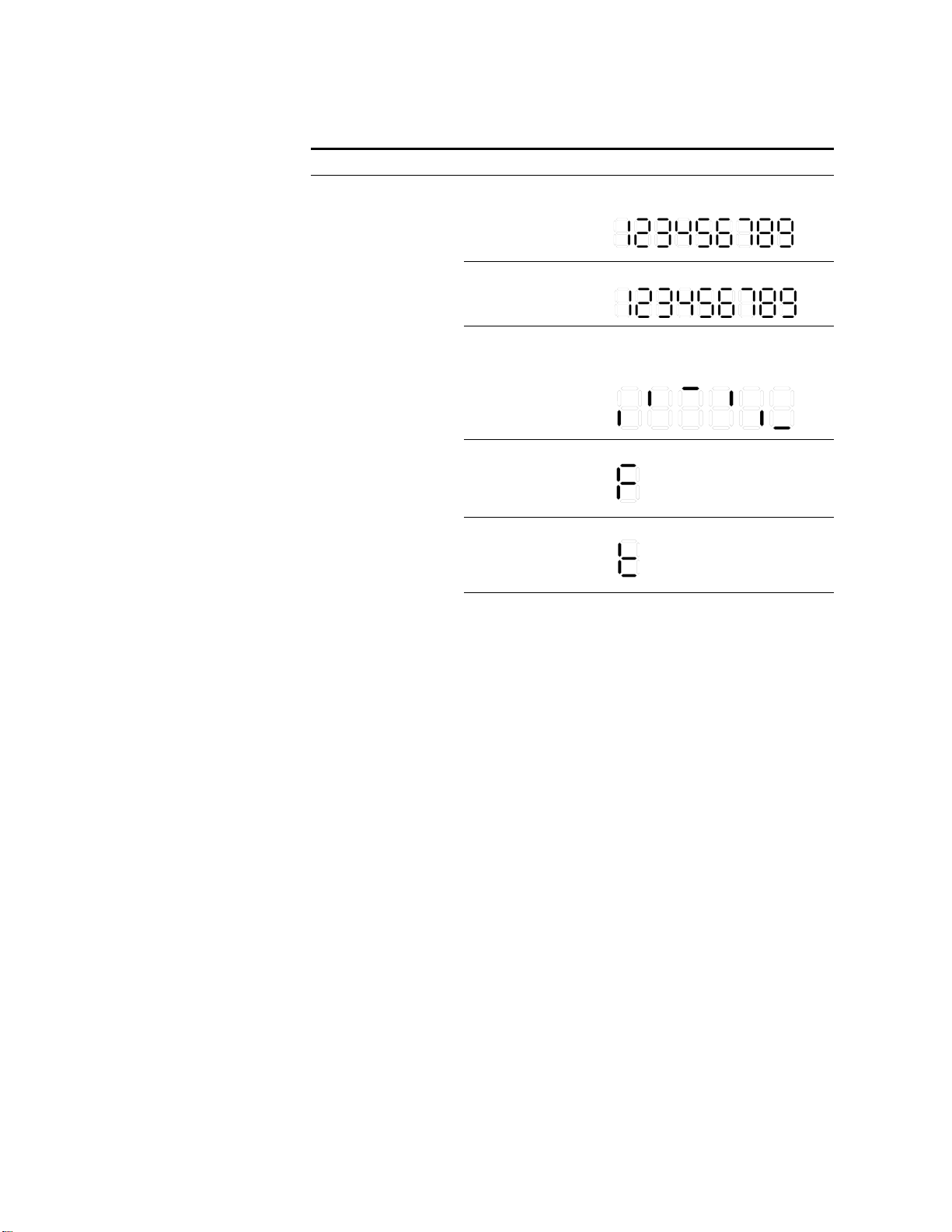
Table 3 Switch 4500G 24-Port and 48-Port Front Panel LEDs
LED Label Status Description
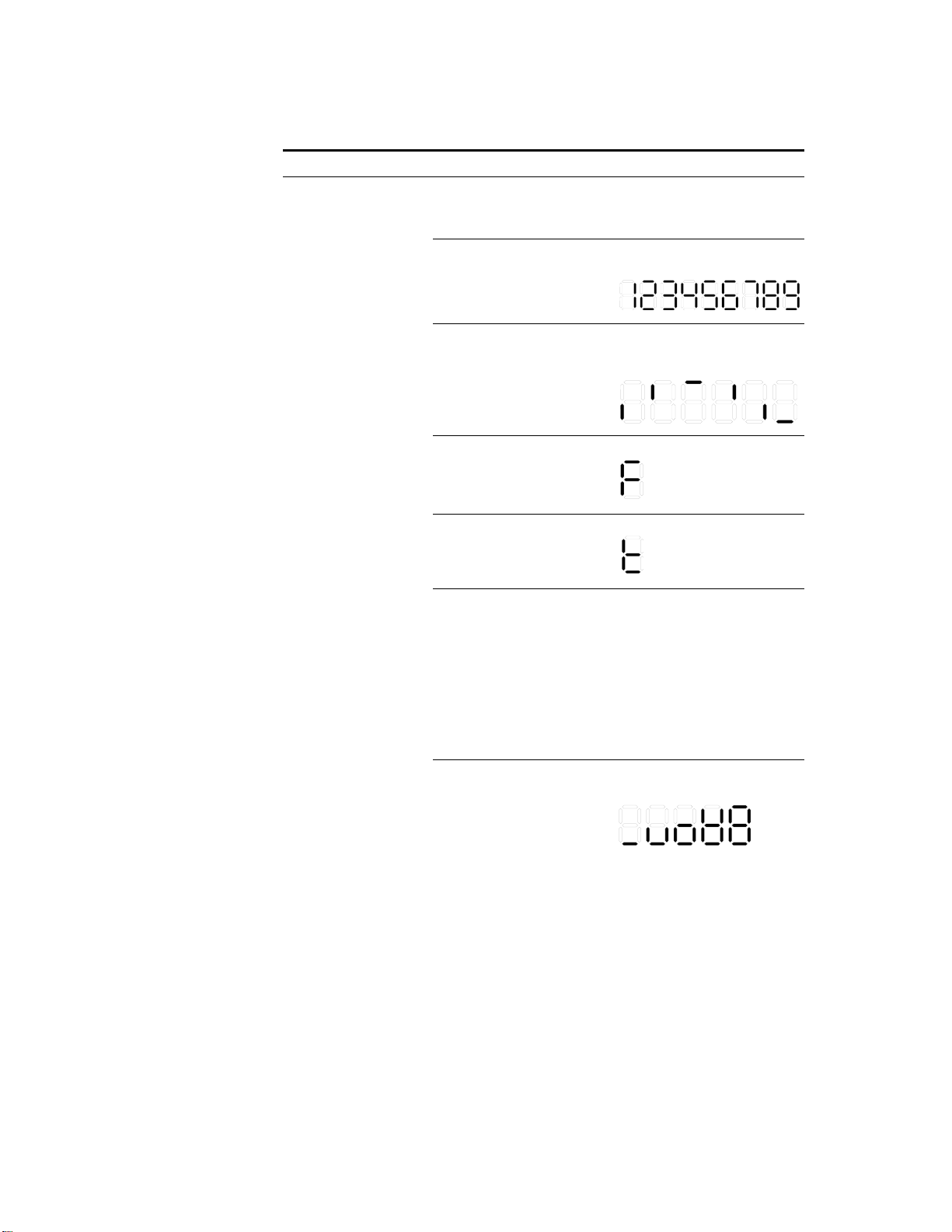
7-segment
digitron
Unit POST
running
Green,
blinking
The POST ID of the in-process test is
displayed.
display
POST
failed
Loading
software
Fan
failure
Overtemp
erature
alarm
Cluster
status
Red,
The POST ID of the failed test blinks.
blinking
Green,
blinking
A light bar rotates clockwise around
the display during the loading
procedure.
Red, ON An “F” is displayed.
Red, ON A “t” is displayed.
Green, ON A “C” is displayed if this is a
command switch.
An “S” is displayed if this is a
member switch.
A “c” is displayed if this is a
candidate switch.
A “1” is displayed when the switch
operates independently.
Page 12

12 CHAPTER 1: INTRODUCING THE SWITCH 4500G FAMILY
Table 3 Switch 4500G 24-Port and 48-Port Front Panel LEDs
LED Label Status Description
10/100/1000
BASE-T
Ethernet port
status LED
1000Base SFP
port status
LED
Rate
mode
Duplex
mode
This LED
is not
influence
d by the
mode
button
Green The port works at the rate of 1000
Mbps; the LED blinks quickly when
the port is sending or receiving
data.
Yellow The port works at the rate of
10/100 Mbps; the LED blinks quickly
when the port is sending or
receiving data.
Yellow,
blinking
(3 Hz)
OFF The port is not connected.
Green The port works in full duplex mode;
Yellow The port works in half duplex mode;
Yellow,
blinking
(3 Hz)
OFF The port is not connected.
Green The port works at the rate of 1000
Yellow,
blinking
(3 Hz)
OFF The port is not connected.
POST fails on the port.
the LED blinks quickly when the
port is sending or receiving data.
the LED blinks quickly when the
port is sending or receiving data.
POST fails on the port.
Mbps; the LED blinks quickly when
the port is sending or receiving
data.
POST fails on the port.
Page 13
Switch 4500G PWR 24-Port and 48-Port —Front and Rear Panel Detail 13
(1) (2)
(3)
(4)
(5)
(1) (2)
(3)
(4)
(5)
Switch 4500G PWR
24-Port and 48-Port
—Front and Rear
Panel Detail
Figure 5 displays the front panel of the Switch 4500G PWR 24-Port unit.
Figure 5 Switch 4500G PWR 24-Port Front Unit’s Front Panel
(1) 10/100/1000 BASE-T autosensing
Ethernet port status LEDs
(3) Console port (4) 7-segment digitron display
(5) Power LED (6) DC power LED
(7) LED for extended slot 1 (8) LED for extended slot 2
(9) Mode LED (10) Mode switching button
(2) Gigabit SFP Combo port status LED
Figure 6 displays the rear panel of the Switch 4500G PWR 24-Port Ethernet
Switch.
Figure 6 Switch 4500G PWR 24-Port Unit’s Rear Panel
(1) 10/100/1000 BASE-T autosensing
Ethernet port status LED
(3) Grounding terminal (4) Extended slot 1
(5) Extended slot 2
(2) AC power input
Page 14
14 CHAPTER 1: INTRODUCING THE SWITCH 4500G FAMILY
(7)
(8)
(9)
(1) (2)
(3)
(4)
(5)
(1) (2)
(3)
(4)
(5)
(2)
(3)
(4)
Figure 7 displays the Switch 4500G PWR 48-Port unit’s front panel.
Figure 7 Switch 4500G PWR 48-Port Unit’s Front panel
(1) 10/100/1000 BASE-T autosensing
Ethernet port status LEDs
(3) 7-segment digitron display (4) Mode switching button
(5) Mode LED (6) Power LED
(7) LED for extended slot 1 (8) LED for extended slot 2
(9) Gigabit SFP Combo port status LED
(2) Console port
Figure 8 describes the Switch 4500G PWR 48-Port unit’s rear panel.
Figure 8 Switch 4500G PWR 48-Port Unit’s Rear Panel
(1) AC power input (2) Grounding terminal
(3) Extended slot 1 (4) Extended slot 2
Page 15

Switch 4500G PWR 24-Port and 48-Port Front Panel LEDs 15
Switch 4500G PWR 24-Port and 48-Port Front Panel LEDs
Ta bl e 4 describes the Switch 4500G PWR 24-Port and PWR 48-Port units’ LEDs.
Table 4 Switch 4500G PWR 24-Port and 48-Port Front Panel LEDs
LED Label Status Description
Mode LED Mode Rate mode Green, ON The port status LEDs are
showing the port rate.
Duplex
mode
PoE mode Green,
Power LED PWR Green, ON The switch starts normally.
Green, blinking (1 Hz) The system is performing
Red, ON The POST fails the POST.
Yellow, blinking (1 Hz) One or more ports fail the
OFF The switch is powered off.
Module LED Module
(MOD)
Green, ON The module is installed and
Yellow, blinking The module is not supported
OFF The module is not installed.
Yellow, ON The port status LEDs are
blinking (1 Hz)
showing the duplex mode of
the port.
The port status LEDs are
showing the PoE status of the
port.
power-on self test (POST).
POST.
operates normally.
or is in trouble.
Page 16
16 CHAPTER 1: INTRODUCING THE SWITCH 4500G FAMILY
0 - 20%
21 - 4 0%
41 - 6 0%
61 - 8 0%
81 - 1 00%
Table 4 Switch 4500G PWR 24-Port and 48-Port Front Panel LEDs
LED Label Status Description
7-segment
Unit POST
digitron
display
running
Green,
blinking
The POST ID of the in-process
test is displayed.
POST failed Red, blinking The POST ID of the failed test
blinks.
Loading
software
Green,
blinking
A light bar rotates clockwise
around the display during the
loading procedure.
Fan failure Red, ON An “F” is displayed.
Overtemper
Red, ON A “t” is displayed.
ature alarm
Cluster
status
Green, ON A “C” is displayed if there is a
command switches.
An “S” is displayed if there is
a member switches.
A “c” is displayed if there is a
candidate switches.
A “1” is displayed when the
switch operates
independently.
PoE mode Green, ON Show the utilization of the
power
Page 17

Switch 4500G PWR 24-Port and 48-Port Front Panel LEDs 17
Table 4 Switch 4500G PWR 24-Port and 48-Port Front Panel LEDs
LED Label Status Description
10/100/1000
BASE-T
Ethernet port
status LED
10/100/1000
BASE-T
Ethernet port
status LED
(continued)
1000 Base
SFP port
status LED
None Rate mode Green The port works at the rate of
1000 Mbps; the LED blinks
quickly when the port is
sending or receiving data.
Duplex
mode
PoE mode Green, ON The port supplies power
None PoE mode
(continued)
None This LED is
not
influenced
by the mode
button
Yellow The port works at the rate of
Yellow,
blinking (3 Hz)
OFF The port is not connected.
Green The port works in full duplex
Yellow The port works in half duplex
Yellow,
blinking (3 Hz)
OFF The port is not connected.
Green,
blinking (1 Hz)
Yellow, ON The devices attached to the
Yellow,
blinking (3 Hz)
OFF The port does not supply
Green The port works at the rate of
Yellow,
blinking (3 Hz)
OFF The port is not connected.
10/100 Mbps; the LED blinks
quickly when the port is
sending or receiving data.
POST fails on the port.
mode; the LED blinks quickly
when the port is sending or
receiving data.
mode; the LED blinks quickly
when the port is sending or
receiving data.
POST fails on the port.
normally
The required power of the
attached devices has exceeded
the maximum power that the
port can supply.
The total power that the
switch supplies has reached
the maximum power, so the
port does not supply power
any more.
port are not powered devices
(PDs), so the port does not
supply power.
The PoE power fails, so the
port cannot supply power.
POST fails on the port
power.
1000 Mbps; the LED blinks
quickly when the port is
sending or receiving data.
POST fails on the port.
Page 18

18 CHAPTER 1: INTRODUCING THE SWITCH 4500G FAMILY
System Specifications of the Switch 4500G
Ta bl e 5 provides the system specifications for the Switch 4500G.
Table 5 System specifications of the Switch 4500G
Switch 4500G
24-Port
Item
Physical
dimensions
(H W D)
Weight 4 kg (8.8 lb) 4.5 kg (9.9 lb) 6 kg (13.2 lb) 6.5 kg (14.3 lb)
Console port One Console port
GE ports on
the front
panel
Optional
interface
modules
AC Input
voltage
Power
consumption
(full load)
Operating
temperature
Relative
humidity
(noncondensing)
3CR17761-91
43.6 440 300 mm
(1.72 17.3 11.8 in.)
24 ×
10/100/100
Mbps Ethernet
ports
Four Gigabit SFP
Combo ports
Switch 4500G 2-port 10-Gigabyte Module, 3C17766
Switch 4500G 2-port Local Connection Module, 3C17767
Switch 4500G 1-port 10-Gigabyte Module, 3C17768
Rated voltage range: 100 VAC to 240 VAC, 50/60 Hz
Max voltage range: 90 VAC to 264 VAC, 47/63 Hz
80 W 120 W 455 W, with 85
0°C to 45°C (32°F to 113°F)
10% to 90%
Switch 4500G
48-Port
3CR17762-91
48 ×
10/100/100
Mbps Ethernet
ports
Four Gigabit SFP
Combo ports
Switch 4500G
PWR 24-Port
3CR17771-91
43.6 440 420 mm
(1.72 17.3 16.5 in.)
24 ×
10/100/100
Mbps Ethernet
ports
Four Gigabit SFP
Combo ports
W of system
power
consumption
and 370 W of
PoE power
Switch 4500G
PWR 48-Port
3CR17772-91
48 ×
10/100/100
Mbps Ethernet
ports
Four Gigabit SFP
Combo ports
500 W when
RPS is not
connected, with
130 W of
system power
consumption
and 370 W of
PoE power
870 W when
RPS is
connected, with
130 W of
system power
consumption
and 740 W of
PoE power
Page 19

2
INSTALLING THE SWITCH
This section contains information that you need to install and set up your 3Com®
switch. For information on upgrading your switch, refer to the Switch 4500G
Release Notes available at www.3com.com.
WARNING: Safety Information. Before you install or remove any components
from the Switch or carry out any maintenance procedures, you must read the
3Com Switch Family Safety and Regulatory Information document enclosed
with your switch as well as
Information” on page 73.
AVERTISSEMENT: Consignes de securite. AAvant d’installer ou d’enlever un
composant du commutateur ou de réaliser une procédure de maintenance, vous
devez prendre connaissance du document 3Com Switch Family Safety and
Regulatory Information accompagnant le commutateur ainsi que de l’annexe D,
“Redundant Power Supply Safety Information” on page 73.
Appendix E, “Redundant Power Supply Safety
VORSICHT: Sicherheitsinformationen. Bevor Sie dem Switch Komponenten
hinzufügen oder daraus entfernten oder Wartungsaufgaben durchführen, müssen
Sie das dem Switch beigefügte Dokument 3Com Switch Family Safety and
Regulatory Information (Sicherheitsinformationen und Betriebsbestimmungen
der 3Com Switchfamilie) sowie Anhang D,
Information” on page 73 lesen.
ADVERTENCIA: Información de seguridad. Antes de instalar o suprimir
cualquier componente del conmutador o de realizar cualquier tarea de
mantenimiento, debe leer el documento 3Com Switch Family Safety and
Regulatory Information adjunto con el conmutador así como el Apéndice D,
“Redundant Power Supply Safety Information” on page 73.
AVVERTENZA: Informazioni di sicurezza. Prima di installare o rimuovere
qualsiasi componente dallo Switch o di eseguire qualsiasi procedura di
manutenzione, leggere il documento 3Com Switch Family Safety and
Regulatory Information fornito con lo switch e l'Appendice D,
Power Supply Safety Information” on page 73.
OSTRZEŻENIE: Informacje o zabezpieczeniach. Przed zainstalowaniem lub
pozbyciem się jakiegokolwiek elementu z Przełącznika lub przeprowadzeniem
jakichkolwiek czynności konserwacyjnych, należy obowiązkowo przeczytać
3Com Switch Family Safety and Regulatory Information dołączone do
przełącznika oraz w Załączniku D, “Redundant Power Supply Safety Information”
on page 73.
“Redundant Power Supply Safety
“Redundant
CAUTION: Opening the switch or tampering with the warranty sticker can void
your warranty.
Page 20
20 CHAPTER 2: INSTALLING THE SWITCH
ATTENTION : le fait d’ouvrir le commutateur ou d’altérer la vignette de garantie
pourrait rendre la garantie nulle.
WARNUNG: Öffnen des Switches oder Manipulation des Garantieaufklebers kann
das Erlöschen der Garantie zur Folge haben.
PRECAUCIÓN: si se abre el conmutador o se manipula el adhesivo de la garantía,
ésta quedará invalidada.
ATTENZIONE: L'apertura dello switch o la manomissione dell'adesivo di garanzia
può invalidare la garanzia.
OSTRZEŻENIE: Otwarcie przełącznika lub naruszenie plomby gwarancyjnej
może unieważnić gwarancję.
Rack-Mounting the Switch
Follow the steps below to mount your switch in a standard 19-inch rack:
1 Check that the rack is sturdy and properly grounded. Attach the rack-mount
brackets to the front or rear panel of the chassis with screws.
2 Place the switch on a shelf in the rack and slide it to a proper position along the
guide rails, reserving a suitable clearance between the device and the guide rails.
3 Fix the brackets to the rack posts with screws, making sure that the device is
securely attached.
Page 21
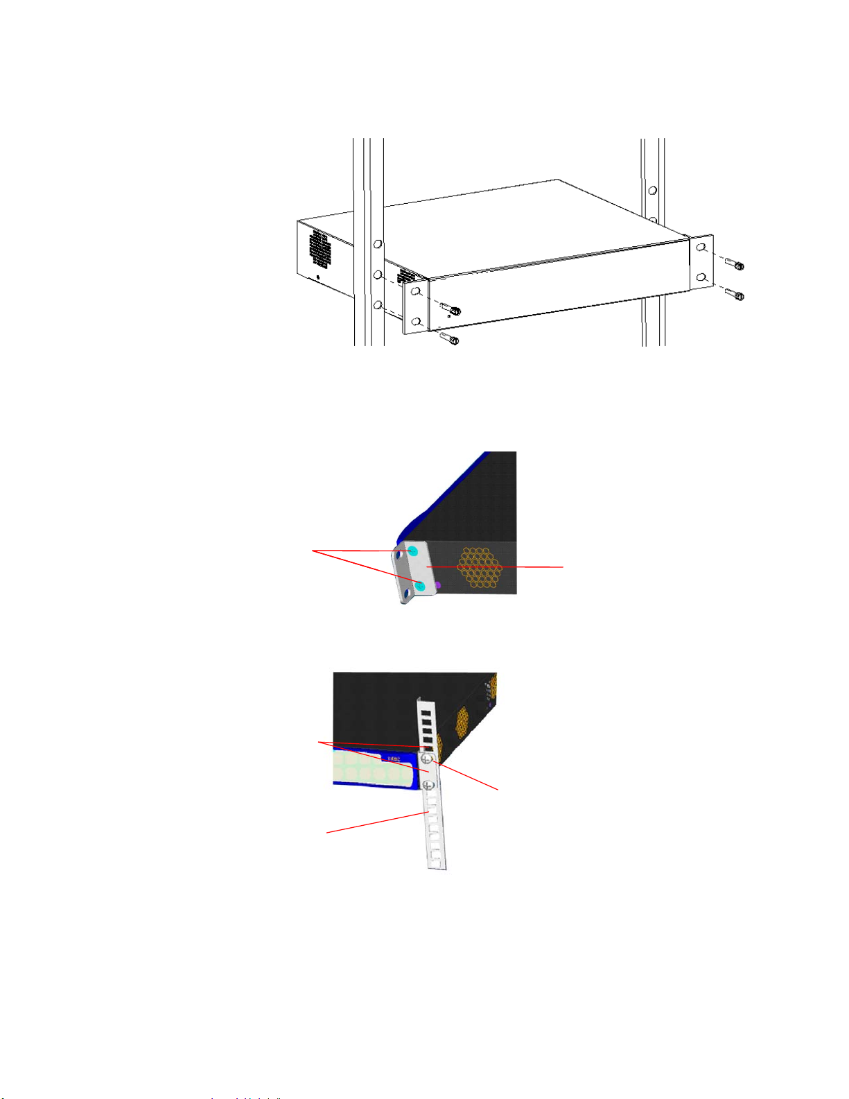
Figure 9 Installing the switch in a 19-inch rack
Front
bracket
Screw
Front
bracket
Screw
Screw
Front mount angle
Front
bracket
Screw
Front mount angle
Front
bracket
Rack-Mounting the Switch 21
Mounting the Front
bracket
Mount the front bracket as shown in Figure 10 and Figure 11.
Figure 10 Mount the front bracket to the device
Figure 11 Mount the front bracket to the mount angel of the rack
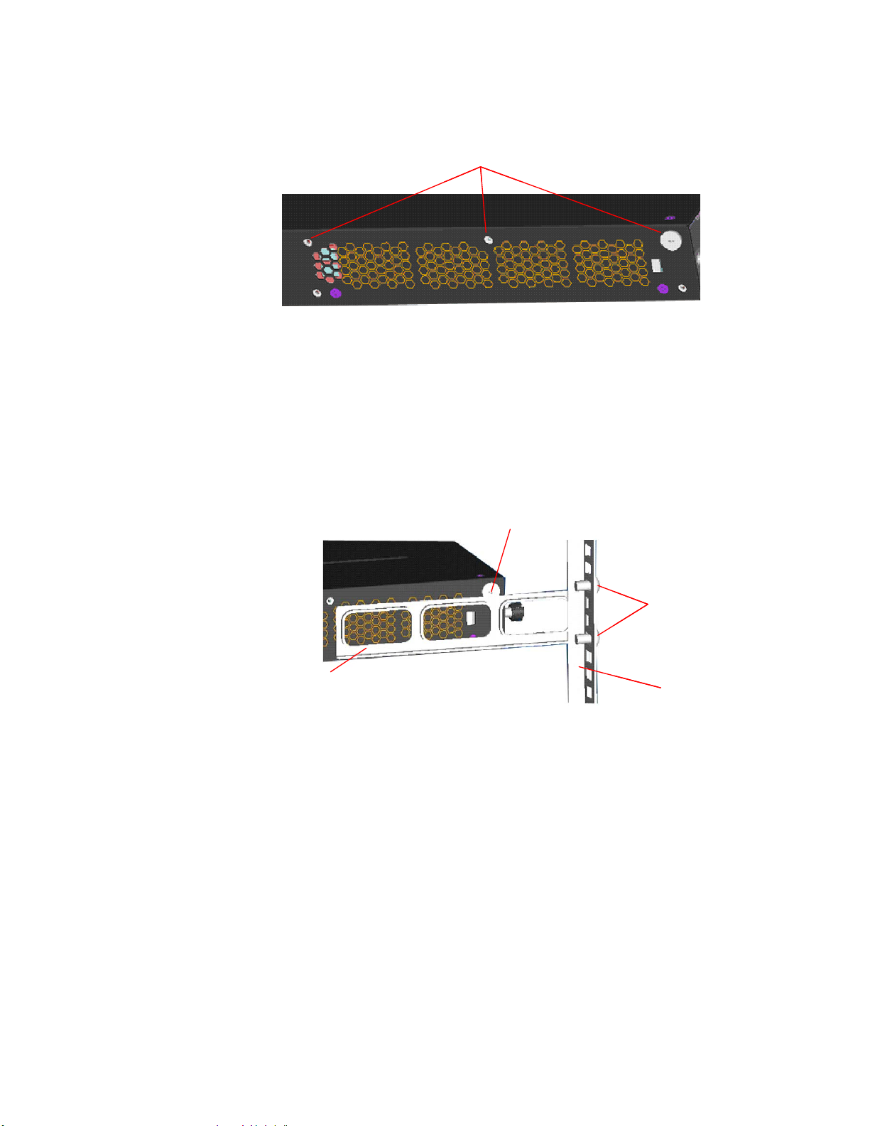
Mounting the Rear
Bracket
The Switch 4500G 24-Port and Switch 4500G 48-Port units do not need rear
brackets. The description on mounting rear brackets is only for the Switch 4500G
PWR 24-Port and Switch 4500G PWR 48-Port.
Mount a screw on the back of the switch to closely connect the switch with the
rear bracket to support the switch. There are three positions for screw mounting
as shown in
Figure 12.
Page 22
22 CHAPTER 2: INSTALLING THE SWITCH
Three positions for screw mountingThree positions for screw mounting
Screw 1
Screw 2
Rear brac ket
Rear mount
angle
Screw 1
Screw 2
Rear brac ket
Rear mount
angle
Figure 12 Positions for screw mounting on the switch
Follow the steps below to mount the rear bracket:
1 Use screws to fix the rear bracket to the rear mount angle.
2 Determine the position for screw mounting on the switch according to the
position of the mount angle.
3 Mount the screw to the switch and make sure the screw and the rear bracket are
closely connected.
Figure 13 Installation completed 1
Screw 1: Fix the rear bracket to the mount
angle.
Screw 2 is mounted to the switch.
Page 23
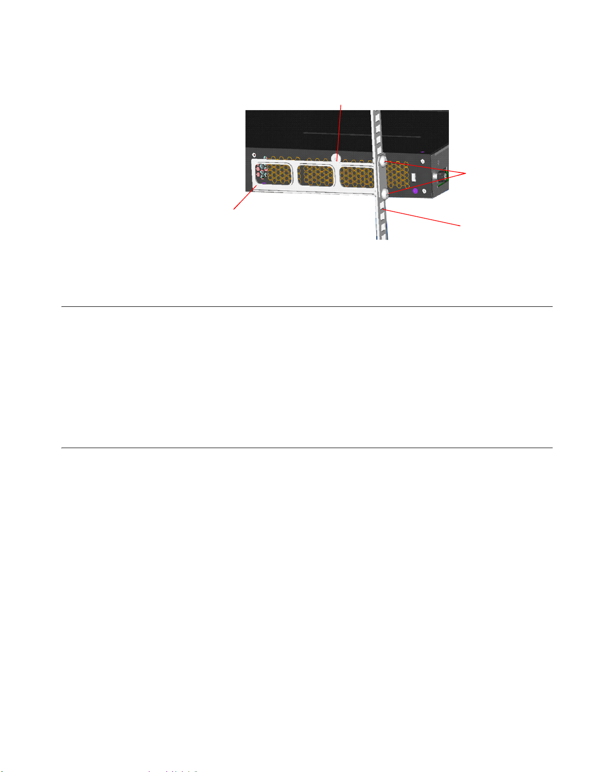
Figure 14 Installation completed 2
Screw 2
Screw 1
Rear mount angle
Rear bracket
Screw 2
Screw 1
Rear mount angle
Rear bracket
Mounting the Switch on a Desktop 23
Mounting the Switch on a Desktop
The Power-up Sequence
Powering-up the Switch
4500G
1 Plug the power cord into the power socket at the rear of the Switch.
Screw 1: Fix the rear bracket to the mount
angle.
Screw 2 is mounted to the switch.
In many cases, standard 19-inch racks are not available. Therefore, switches are
often placed on a desktop. To place your switch on a desktop, you simply need to:
■ Make sure that the surface is clean, flat, and sturdy.
■ Makes sure that the environment is well ventilated and allow 10 cm (3.9 in.) of
space around the chassis for heat dissipation.
■ Do not place heavy objects on your switch.
■ When stacking, the vertical distance between two switches must be at least 1.5
cm (0.59 in).
The following sections describe how to get your Switch 4500G powered-up and
ready for operation.
Use the following sequence of steps to power-up the Switch.
2 Plug the other end of the power cord into your power outlet.
Checking for Correct
Operation of LEDs
The Switch powers-up and runs through its Power On Self Test (POST), which
takes approximately one minute.
During the Power On Self Test, all ports on the Switch are disabled and the LEDs
light. The PWR LED will flash green during the POST.
When the POST has completed, check the PWR LED to make sure that your Switch
is operating correctly.
Ta bl e 6 shows possible colors for the LED.
Page 24
24 CHAPTER 2: INSTALLING THE SWITCH
Ta bl e 6 PWR LED Colors
Color State
Green The Switch is powered-up and operating normally.
Red The Switch has failed its Power On Self Test (POST).
Yellow flashing Some ports have failed POST
Off The Switch is not receiving power.
* In this event you can still use the Switch using the remaining ports that have passed the
POST.
If there is evidence of a problem, see “Solving Problems Indicated by LEDs” on
page 52 for a list of suggested solutions.
CAUTION: The Switch has no ON/OFF switch; the only method of connecting or
disconnecting mains power is by connecting or disconnecting the power cord.
*
Connecting a Redundant Power Supply
The Switch 4500G 26-port PWR has a -48V DC Redundant Power Supply socket.
WARNING: Only properly trained and qualified personnel should install the
Redundant Power Supply (RPS).
WARNING: Make sure to read these instructions in conjunction with the RPS flyer
and the safety and installation instructions supplied with your RPS.
Page 25

Connecting a Redundant Power Supply 25
WARNING: When powering any Switch 4500G from an RPS, make sure that the
unit is earthed (grounded) by either connecting the power cord to the unit or by
connecting the earth terminal on the rear of the unit to a reliable electrical earth
(or by connecting both). Ensure that the earth connection is made before
connecting the DC supply from the RPS.
3Com switches that support -48V DC RPS inputs, and are PoE enabled, can only
be powered by an RPS that complies with the isolation requirements of IEEE-Std
802.3af. Non PoE enabled switches do not have this restriction.
WARNING: Do not use a standard 'positive-earthed' -48V redundant power
system suitable for use with telecommunications equipment with the 3Com
Power-over-Ethernet (PoE) network switches. In order to meet the IEEE 802.3af
(PoE) specification, the -48V output must be isolated from earth (ground) and
meet the isolation requirements in that specification.
WARNING: Any RPS must be approved as a SELV output in accordance with IEC
60950-1/UL 60950-1/EN 60950-1.
WARNING: The characteristics of the Switch 4500G DC supply input are provided
in Tab le 11 on page 19.
Specifying the
Redundant Power
System
You can power the Switch 4500G using three methods:
■ AC Mains only — this does not offer any power redundancy. If the AC mains
supply or the AC power supply fails, the switch powers off.
■ AC Mains and -48V DC (primary supply) — the internal AC supply acts as
the backup in the event of a DC power failure.
■ DC only — the switch does not need an AC supply and the resiliency is
provided by the DC supply. This is useful in environments where only DC power
is available.
The RPS provides two main benefits:
■ Power Redundancy — if a switch is powered from the mains supply unit, a
failure of the internal power supply causes the switch to fail. You can avoid this
by connecting both the AC and DC RPS supplies to the switch. You can also
add redundancy to the DC power by using (N+1) DC power supplies to further
increase the availability of the system.
■ Uninterruptable Power — the system allows easy connection and
maintenance of batteries to the RPS shelf to further increase the availability of
the system.
3Com’s redundant power solution allows you to use any off-the-shelf -48V DC
RPS that meets the requirements defined in
Ta bl e 11 on page 19.
For an approved vendor list, more details about purchasing the 3Com
recommended RPS, and a full set of requirements go to:
http://www.3Com.com/RPS
The 3Com recommended RPS generates -48V DC power using power supply units
(or rectifiers). The outputs of the rectifier(s) are connected together so that you
can increase the total -48V power available by adding rectifiers. For example, three
Page 26

26 CHAPTER 2: INSTALLING THE SWITCH
1500W rectifiers can provide up to 4500W. Hot removal or insertion of a rectifier
does not affect the -48V DC output voltage.
Ta bl e 7 shows an example of the total power available from several 1500W
rectifiers.
A minimum of two rectifiers are required for each shelf to provide N+1 rectifier
redundancy.
Ta bl e 7 Power Availability
The unearthed -48V DC power distribution provides the mechanism to connect to
the Switch 4500G. The distribution consists of several circuit breakers and
connection terminals for the positive (common) and negative -48V outputs.
Individually connect each Switch 4500G to a circuit breaker terminal.
No Rectifier
Redundancy
N+1 Rectifier
Redundancy
Rectifiers
1 2 3 4 5 6
1500W 3000W 4500W 6000W 7500W 9000W
- 1500W 3000W 4500W 6000W 7500W
Connecting the Switch
to the Redundant Power
System
You can also connect a battery to battery terminals prior to the DC power
distribution to provide uninterrupted power and to be protected against the loss
of AC mains power.
3Com’s RPS solution uses -48V DC power distribution. The RPS system provides
bulk -48V DC power that is separately distributed to a number of network
switches.
Each RPS consists of a shelf that can house from one to six rectifiers, a Distribution
Module, and a Management Module.
When connecting the RPS to the switch, the circuit breaker and 2-core cables need
to be matched to the switch’s power rating.
Ta bl e 8 shows the recommended
circuit breaker and cable rating for the Switch 4500G. The recommended cable
length should not exceed three metres (9.84 feet).
Ta bl e 8 Switch 4500G Circuit Breaker and Cable Ratings
Circuit Breaker Minimum 2-Core Cable Diameter
PoE 25A C type 12 AWG (solid or stranded cable)
WARNING: Make sure to follow the RPS Manufacturers recommendations when
connecting the cable to the RPS.
WARNING: Ensure that the circuit breaker in the RPS is in the open (off) position
when connecting the cable to the RPS and the cable and connector to the switch.
WARNING: Ensure that the positive terminal on the switch is connected to the
positive (common) terminal of the RPS and that the negative terminal on the
switch is connected to the negative (circuit breaker) terminal of the RPS.
Page 27

Connecting a Redundant Power Supply 27
+
-
NULL
-48 -60V;2.0A
100-240V;50/60Hz;1.0A
~
NULL
-48 -60V;2 0A
Null
+
-
Pinout
Cable Tie
Figure 15 shows how to connect the power supply to the RPS socket in the back
of the switch. Use the cable tie supplied with your switch to support the cable in
the back of the RPS connector as shown in
Figure 15 RPS Connection to the Switch
Figure 15.
Connecting the Earthing
Using Power over
Ethernet
Cable
When the RPS is connected to the switch, you can move the circuit breaker in the
RPS to the closed (on) position and the switch will be powered by the -48V DC
power.
The -48V DC power takes priority over the AC mains and powers the switch if it is
connected.
Use the earthing cable that accompanies your switch if the length is suitable.
Alternatively use the earthing cable specification as defined in
“Earthing Lead” on
page 20.
The earthing cable is only required if the switch is powered by the RPS only.
The recommended cable length should not exceed three meters (9.84 feet).
The Switch 4500G Power over Ethernet (PoE) units can supply power to any IEEE
802.3af compliant device through any of its front panel ports over a Category 5 or
Category 5e Ethernet cable. The same cable connects the device to the network.
The Switch 4500G units can supply power through the 10/100 ports only.
Power over Ethernet is a self-configuring protocol. When you plug a PoE
compliant device into one of the ports on the switch, the switch supplies the
Page 28

28 CHAPTER 2: INSTALLING THE SWITCH
power required to the device, providing that the total power budget for the switch
is not exceeded.
A PoE switch combines the functionality of a standard Ethernet switch with a
single power supply that can power multiple devices. Using a PoE switch has the
following advantages over an non-powered network.
■ Reduced Cabling — a PoE (802.3af) compliant device that has its power
■ Increased Reliability — a device powered by a PoE switch can take advantage
The switch supports resistor detection according to IEEE 802.3af and pre-standard
detection methods.
The Switch 4500G supports 3Com 802.3af equipment. For the latest list of
supported devices, refer to the product page on the 3Com web site at
http://www.3com.com/
supplied over its Ethernet cable does not require a separate power supply. If,
for example, you use the switch to connect a 3Com 11 Mbps Wireless LAN
Access Point 8500 to the network, then only a network cable is required to
provide both power and network connectivity.
of the facilities available to the switch. You can fit the switch with a redundant
power supply or uninterruptible power supply to increase its uptime.
Connecting Console Cable
Console Cable A Console cable is an 8-core cable. One end of the cable is a crimped RJ-45
For additional information on Power over Ethernet, refer to the Power over
Ethernet Configuration chapter in the Configuration Guide available on the 3Com
Web site. Power over Ethernet management is available using the web interface or
the command line interface (CLI).
connector for the connection to the Console port of the switch, and the other end
is a DB-9 female connector for the connection to the serial port on the Console
terminal, as shown in
Figure 16 Console cable
Figure 16.
Page 29

Connecting Console Cable 29
Table 9 Console cable pinouts
RJ-45 Signal Direction DB9 (modem) DB9 (console)
1 RTS — 7 8
2 DTR — 4 6
3 TXD — 3 2
4 CD — 1 5
5 GND — 5 5
6 RXD — 2 3
7 DSR — 6 4
8 CTS — 8 7
When you want to use the terminal to configure the switch, follow these steps to
connect a terminal device to your switch using console cables:
1 Plug the DB-9 female connector of the Console cable to the serial port of the PC
or terminal where the switch is to be configured.
2 Connect the RJ-45 connector of the Console cable to the Console port of the
switch.
CAUTION: Pay attention to the mark on the Console port and be sure to plug the
connector to the right port.
If the switch has been powered on:
■ First connect the DB-9 connector of the Console cable to the PC before
connecting the RJ-45 connector to the switch.
■ Disconnect the DB-9 connector of the Console cable from the PC after
disconnecting the RJ-45 connector from the switch.
Page 30

30 CHAPTER 2: INSTALLING THE SWITCH
Page 31

3
SETTING UP SWITCH MANAGEMENT
To make full use of the features offered by your switch, and to change and
monitor the way it works, you have to access the management software that
resides on the switch. Managing the switch can help you to improve the efficiency
of the switch and therefore the overall performance of your network.
This chapter explains the initial set up of the switch and the different methods of
accessing the management software to manage a switch. It covers the following
topics:
■ Methods of Managing a Switch
■ Setting Up Your Switch
■ Manually Configuring IP Information
■ Viewing Automatically Configured IP Information
■ Setting Up Command Line Interface Management
Methods of Managing a Switch
Command Line Interface
Management
■ Setting Up Command Line Interface Management using SSH
■ Setting Up Web Interface Management
■ Setting Up SNMP Management V1 or V2
■ Default Users and Passwords
■ For information on the lost password procedure please refer to the
Configuration Guide that is supplied with your switch.
You can manage your switch using the:
■ Command line interface
■ Command line interface using SSH
■ Web interface
■ SNMP
Each switch has a command line interface (CLI) that allows you to manage the
switch from a workstation, either locally using a console port connection (see
Figure 17), or remotely over the network (see Figure 18).
Page 32

32 CHAPTER 3: SETTING UP SWITCH MANAGEMENT
Console Port
Connection
Workstation
(with terminal emulation
software installed)
Console Cable
Switch
Switch
Workstation
Connect over Network
via Telnet
Workstation
Switch
Connect over Network
via web browser
Figure 17 CLI Management using the Console Port
Figure 18 CLI Management over the Network
Refer to “Setting Up Command Line Interface Management” on page 44.
There are two main views in the CLI:
Command Line Interface
Management using SSH
Web Interface
Management
■ User View
This view is shown when you first connect to the switch and shows basic
information about operation and statistics. The prompt for user view is
<4500G>.
■ System View
This view enables you to configure the system parameters. To display this view,
from user view enter system-view. The prompt for system view is [4500G].
The Switch 4500G supports Secure Shell version 2.0 (SSHv2.0), allowing secure
access to the switch’s Command Line Interface.
If you use SSH to administer your switch and the network traffic is intercepted, no
passwords or configuration information will be visible in the data. To securely
administer the switch using the Command Line Interface you need a third party
SSH client.
Each switch has an internal set of web pages that allow you to manage the switch
using a Web browser remotely over an IP network (see
Figure 19 Web Interface Management over the Network
Figure 19).
Refer to “Setting Up Web Interface Management” on page 45.
Page 33

Setting Up Your Switch 33
SNMP Network Management
Workstation
Switch
Connect over Network
using SNMP
SNMP Management You can manage a switch using any network management workstation running
the Simple Network Management Protocol (SNMP) as shown in
Figure 20. For
example, you can use the 3Com Network Director software, available from the
3Com website. For information on the 3Com’s network management tools, refer
Appendix D on page 69.
to
Figure 20 SNMP Management over the Network
Refer to “Setting Up SNMP Management V1 or V2” on page 46.
Setting Up Your Switch
This section provides an overview of what you need to do to get your switch set
up and ready for management when it is in its default state. The whole setup
process is summarized in
Figure 21. Detailed steps are contained in the sections
that follow. In brief, you need to:
■ Configure IP information manually for your switch or view the automatically
configured IP information.
■ Prepare for your chosen method of management.
Page 34

34 CHAPTER 3: SETTING UP SWITCH MANAGEMENT
Plug and Play Setup
Initial IP Information Set up
Feature Management
Power Up the Switch.
IP Information is automatica lly configured
using DHCP
See page 35
Do you want to manually
configure the IP information?
Connect to the console port and use the
Command Line Inter-
face.
See page 36
How do you want to manage your Switch? See page 31
SNMP
See page 46
Command Line Interface
Connect using the
console port.
See page 44
Web Interface
Connect over the
network using Telnet.
See page 44
Connect over the
network.
See page 46
How do you want to view the automatically
configured IP information?
How do you want to connect to the Switch?
Connect to a front panel port
and use the Web Interface or
Command Line
Interface.
See page 36
Use 3Com Network
Director (3ND).
See page 42
Connect to the console
port and use the
Command Line
Interface.
See page 43
Yes
No
Figure 21 Initial Switch Setup and Management Flow Diagram
IP Configuration You can use one of the following methods to allocate IP information to your
CAUTION: To protect your switch from unauthorized access, you must change all
three default passwords as soon as possible, even if you do not intend to actively
manage your switch. For more information on default users and changing default
passwords, see
switch (essential if you wish to manage your switch across the network).
Configuring IP Manually
When you configure the IP information, the switch retains the information that
you enter until you change it again. You should configure manually configure the
IP address if:
■ You do not have a DHCP or BootP server on your network.
■ You want to remove the risk of the IP address changing.
■ Your DHCP or BootP server does not allow you to allocate static IP addresses.
“Default Users and Passwords” on page 47.
(Static IP addresses are necessary to ensure that the switch is always allocated
the same IP information.)
Page 35

Setting Up Your Switch 35
For most installations, 3Com recommends that you configure the switch IP
information manually. This makes management simpler and more reliable as it is
not dependent on a DHCP or BootP server, and eliminates the risk of the IP address
changing.
To manually enter IP information for your switch, work through the “Manually
Configuring IP Information” on page 36.
Automatically Configuring the IP Address using DHCP
By default the switch attempts to configure its IP Information by obtaining an IP
address from a DHCP server on the network.
When using automatic IP configuration it is important that the switch’s IP address
is static, otherwise you will not know what the IP address is and it will be difficult
to manage that switch. Most DHCP servers allow you to configure static IP
addresses. Refer to the DHCP server’s documentation for instructions.
For a detailed description of how automatic IP configuration operates, refer to the
Switch 4500G Configuration Guide on 3Com’s Web site at www.3com.com.
You should use DHCP to automatically configure the IP address infomration if:
Preparing to Manage
Your Switch
■ Your network uses DHCP to allocate IP information.
■ Flexibility is needed. If the switch is deployed onto a different subnet, it will
automatically reconfigure itself with an appropriate IP address, instead of you
having to manually reconfigure the switch.
If the switch is not allocated with an automatic IP address, the IP configuration will
be blank or shown as ‘’’’.
If you use the automatic IP configuration method, you need to discover the
automatically allocated IP information before you can begin managing the switch.
Follow the instructions in
“Viewing Automatically Configured IP Information” on
page 42.
Once your switch’s initial set up is complete you can set up your chosen
management method as described in
“Methods of Managing a Switch” on
page 31.
For detailed information about the specific web interface operations and
command line interface commands and problem solving, refer to the “Switch
4500G Command Reference Guide” on the 3Com Web site.
Page 36

36 CHAPTER 3: SETTING UP SWITCH MANAGEMENT
Console Port
Connection
Workstation
(with terminal emulation
software installed)
Console Cable
Switch
Manually Configuring IP Information
Connecting to the
Console Port
You can manually configure the switch’s IP information by:
■ Connecting a workstation to the switch’s console port using a console cable.
You can then manually enter the IP information using the command line
interface (CLI).
■ Connecting a workstation to one of the port’s on the switch’s front panel using
an Ethernet cable. You can then manually enter the IP information using the
web interface or the command line interface.
To set up your switch manually you can make a connection to the console port,
(this example describes a local connection to the console port, rather than one
using a modem). You can do this while the switch is offline, before you connect
the switch to a network, or while the switch is connected to a network.
Prerequisites
■ A workstation with terminal emulation software installed, such as Microsoft
Hyperterminal. This software allows you to communicate with the switch
directly through the console port.
■ Documentation supplied with the terminal emulation software.
■ The console cable (RJ-45) supplied with your switch.
You can find pin-out diagrams for the cable in Appendix A on page 55.
■ IP information including the:
■ IP address
■ subnet mask
■ default gateway
■ management VLAN ID, normally set to the default value (1)
Connecting the Workstation to the Switch
To connec the workstation to the switch, perform the following steps:
1 Connect the workstation to the console port using the console cable as shown in
Figure 22.
Figure 22 Connecting a Workstation to the Switch using the Console Port
To connect the cable:
a Attach the RJ-45 connector on the cable to the switch’s console port.
b Attach the other end of the cable to the workstation and tighten the retaining
screws on the cable to prevent it from being loosened.
2 Open your terminal emulation software and configure the COM port settings to
which you have connected the cable. The settings must be set to match the
default settings for the switch, which are:
Page 37

Manually Configuring IP Information 37
■ 19,200 baud (bits per second)
■ 8 data bits
■ no parity
■ 1 stop bit
■ no hardware flow control
Refer to the documentation that accompanies the terminal emulation software for
more information.
3 Power up the switch. The Power on Self Test (POST) run automatically. The Switch
4500G takes approximately one minute to boot.
Setting Up the Switch with IP Information
You are now ready to manually set up the switch with IP information using the
command line interface.
1 The command line interface login sequence begins as soon as the switch detects a
connection to its console port.
If the login prompt does not begin immediately, press Enter a few times until it
starts.
2 At the login prompts, enter admin as your user name and press Enter. At the
password prompt press Enter again. If you have logged on correctly, <4500G> is
displayed as shown in
Figure 23.
You automatically log on in User View.
Page 38

38 CHAPTER 3: SETTING UP SWITCH MANAGEMENT
Figure 23 User View Login
Starting......
***********************************************************
* *
* Switch 4500G 48-Port BOOTROM, Version 120 *
* *
***********************************************************
Copyright (c) 2004-2007 3Com Corporation and its licensors.
Creation date : Sep 5 2007, 14:07:22
CPU Clock Speed : 264MHz
BUS Clock Speed : 33MHz
Memory Size : 128MB
Mac Address : 0016e0d67c00
Press Ctrl-B to enter Boot Menu... 0
Auto-booting...
Decompress Image................................................................
................................................................................
................................................................................
................................................................................
................................................................................
................................................................................
................................................................................
................................................................................
................................................................................
..................OK!
Starting at 0x80100000...
User interface aux0 is available.
Press ENTER to get started.
Login authentication
Page 39

Manually Configuring IP Information 39
Username:admin
Password:
<4500G>
%Apr 26 12:00:42:811 2000 4500G SHELL/4/LOGIN: admin login from aux0
<4500G>
New diagram for Figure
28:****************************************************************
* All rights reserved (2004-2007) *
* Without the owner's prior written consent, *
* no decompiling or reverse-engineering shall be allowed. *
*****************************************************************
Login authentication
Username:admin
Password:
<4500G>
This a new figure 29:
******************************************************************************
* All rights reserved (2004-2007) *
* Without the owner's prior written consent, *
* no decompiling or reverse-engineering shall be allowed. *
******************************************************************************
User interface aux0 is available.
Please press ENTER.
Login authentication
Username:admin
Password:
<4500G>
%Sep 14 15:04:27:761 2007 4500G SHELL/4/LOGIN: admin login from aux0
<4500G>display ip interface brief
*down: administratively down
(s): spoofing
Interface Physical Protocol IP Address
Vlan-interface1 up up 10.10.23.221
<4500G>
3 Enter the system-view command and press Enter. The [S4500G] prompt is
displayed.
4 Ty pe interface vlan 1 and press Enter.
5 Enter the IP address and subnet mask for the switch as follows:
ip address xxx.xxx.xxx.xxx mmm.mmm.mmm.mmm
(where xxx.xxx.xxx.xxx is the IP address and mmm.mmm.mmm.mmm is the subnet
mask of the switch)
6 Select the quit command and enter the switch’s default gateway:
ip route-static 0.0.0.0 0.0.0.0 xxx.xxx.xxx.xxx
(where xxx.xxx.xxx.xxx is the IP address of the default gateway)
7 From the User View, type save to save the switch’s configuration (this information
is not saved automatically when the switch is powered down).
Page 40

40 CHAPTER 3: SETTING UP SWITCH MANAGEMENT
Front Panel
Port Connection
Ethernet Cable
Workstation
(with a Network
Interface Card
installed)
Switch
You can now set up your chosen management method. See “Methods of
Managing a Switch” on page 31.
If you do not intend to use the command line interface using the console port to
manage the switch, you can disconnect the serial cable and close the terminal
emulator software.
Connecting to a Front
Panel Port
To set up your switch manually you can, alternatively, make a connection to a front
panel port. To do this you will need an IP address, refer to
“Viewing Automatically
Configured IP Information” on page 42 for more information.
The procedure described in this section assumes the unit is powered up in
standalone mode.
Prerequisites
■ A workstation running a suitable operating system. Refer to “Choosing a
Browser” on page 45.
■ A Network Interface Card (NIC).
■ A Category 5 twisted pair Ethernet cable with RJ-45 connectors at both ends.
■ A suitable Web browser. Refer to “Choosing a Browser”on page 45.
■ Existing IP address of the switch.
■ The switch’s IP information, including the:
■ IP address
■ subnet mask
■ default gateway
■ management VLAN ID, normally set to the default value (1)
Connecting the Workstation to the Switch
1 Connect the workstation to a front panel port using an Ethernet cable as shown in
Figure 24.
Figure 24 Connecting a Workstation to the Switch using a Front Panel Port
To connect the cable:
a Attach an RJ-45 connector at one end of the Ethernet cable to the Network
Interface Card (NIC) in the workstation.
b Connect the RJ-45 connector at the other end of the cable to one of the
switch’s front panel ports.
Do not interconnect the switch to any other unconfigured switch.
Page 41

Manually Configuring IP Information 41
Setting Up the Switch with IP Information
You can now review or change the switch’s IP information. You can do this using
the Web interface or the command line interface (CLI) using telnet.
Using the Web Interface
1 Power-up the switch. This takes approximately one minute.
2 Open a suitable Web browser and enter the IP address of your switch in the
Address field.
If there is no response, wait for one minute then re-enter the IP address.
If a pop up message appears displaying download and install simplified Chinese
information, click Cancel.
3 At the login prompt, enter admin as your user name and press Enter and at the
password prompt press Enter again. If you have logged on correctly, the Device
View of the switch is displayed.
4 To enter basic setup information for the switch, select Administration > IP
Setup and then follow the wizard through various system screens to enter the IP
address and subnet mask that you want the switch to use when it is connected to
the network. The final page displays a summary of the information entered.
5 Select Save Configuration to save the configuration to your switch.
The initial setup of your switch is now complete and you can now set up your
chosen management method. See
“Methods of Managing a Switch” on page 31.
Using Command Line Interface with Telnet
1 To start a Telnet session to the unit, click Start in Microsoft Windows.
a Click Run.
b In Open field, type the unit’s IP address:
Telnet xxx.xxx.xxx.xxx
(where xxx.xxx.xxx.xxx is the switch’s IP address)
c Click OK.
2 Press Enter to open a login prompt.
If the login prompt does not begin immediately, press Return a few times until it
starts.
3 At the login prompt, enter admin as your user name and press Return at the
password prompt. If you have logged on correctly, <4500G> is displayed as shown
in the example in
Figure 25.
Page 42

42 CHAPTER 3: SETTING UP SWITCH MANAGEMENT
Figure 25 User View Login using Telnet
4 Enter the system-view command and Enter.
5 Enter interface vlan 1 and Enter.
6 Enter the IP address and subnet mask for the switch as follows:
ip address xxx.xxx.xxx.xxx mmm.mmm.mmm.mmm
(where xxx.xxx.xxx.xxx is the IP address and mmm.mmm.mmm.mmm is the subnet
mask of the switch)
Viewing Automatically Configured IP Information
Using 3Com Network
Director
7 Enter the default gateway for the switch:
ip route-static 0.0.0.0 0.0.0.0 xxx.xxx.xxx.xxx
(where xxx.xxx.xxx.xxx is the IP address of the default gateway)
8 Enter the save command to save the configuration (the configuration is not
saved automatically when the switch is powered down).
The initial set up of your switch is now complete and you can set up your
management method. See
“Methods of Managing a Switch” on page 31.
If you allow the switch to automatically configure its own IP information you need
to discover and view the IP information before you can begin to manage the
switch by:
■ Using 3Com Network Director to auto-discover the switch and display the its
automatically allocated IP information.
■ Connecting a workstation to the switch’s console port using a console cable,
then using the command line interface to view its automatically assigned IP
information.
Each method is described in detail below.
You can use the 3Com Network Director application (available from the 3Com
website) to discover the automatically allocated IP information.
1 Connect your switch to the network.
2 Power-up the switch and wait for two minutes.
3 Launch 3Com Network Director and run the Auto-discovery wizard.
3Com Network Director will auto-discover the new switch and display the IP
information that has been automatically allocated to the switch.
Page 43

Viewing Automatically Configured IP Information 43
Most DHCP and BootP servers allow static IP addresses to be configured so that
you know what IP address the switch will be given. Refer to the documentation
that accompanies your DHCP or BootP server.
If your network does not have a DHCP or BootP server, the workstation running
3Com Network Director must be on the same subnet as the switch, because
Auto-IP addresses are non-routable.
Connecting to the
Console Port
Alternatively, you can view the automatically configured IP information using the
command line interface (CLI) through a connection to the console port. (This
example describes a local connection to the console port, rather than a remote
one using a modem.) For further information on connecting using the console
port see
“Connecting the Workstation to the Switch”on page 36.
Viewing IP Information using the Console Port
You are now ready to view the automatically allocated IP information using the
command line interface.
1 Connect your switch to the network using the Ethernet cable. As soon as a
network connection is made the switch begins the automatic IP configuration
process.
The automatic IP configuration process usually completes within one minute.
2 The command line interface login sequence begins as soon as the switch detects a
connection to its console port.
If the login prompt does not begin immediately, press Return a few times until it
starts.
3 At the login and password prompts, enter admin as your user name and press
Return at the password prompt. If you have logged on correctly, <4500G> is
displayed as shown in the example in
Figure 26.
Figure 26 User View Login
4 Enter display ip interface br to view a summary of allocated IP
addresses.
The initial set up of your switch is now complete and the switch is ready for you to
set up your chosen management method. See
“Methods of Managing a Switch”
on page 31.
Page 44

44 CHAPTER 3: SETTING UP SWITCH MANAGEMENT
If you do not intend to use the command line interface using the console port to
manage the switch, you can logout, disconnect the serial cable and close the
terminal emulator software.
Setting Up Command
Line Interface
This section describes how you can set up command line interface management
using a local console port connection or over the network.
Management
User Interface Overview User interface configuration is provided by the switch to configure and manage
the port data. There are two types of user interfaces:
■ AUX User Interface—used to log in to your switch using the console port. A
fabric can have up to eight AUX user interfaces.
■ VTY User Interface—used to Telnet to the switch. The switch can have up to
five VTY user interfaces.
CLI Management using
the Console Port
CLI Management over
the Network
To manage a switch using the command line interface using the local console port
connection:
1 Ensure you have connected your workstation to the console port correctly as
described in
“Connecting to the Console Port” on page 36.
2 Your switch is now ready to continue being managed and/or configured through
the CLI using its console port.
To manage a switch using the command line interface over a network using
Te ln e t:
1 Ensure you have already set up the switch with IP information as described in
“Methods of Managing a Switch” on page 31.
2 Check that you have the IP protocol correctly installed on your management
workstation. You can check this by trying to browse the World Wide Web. If you
can browse, the IP protocol is installed.
3 Check you can communicate with the switch by entering a ping command at the
DOS prompt in the following format:
c:\ ping xxx.xxx.xxx.xxx
(where xxx.xxx.xxx.xxx is the IP address of the switch)
If you get an error message, check that your IP information has been entered
correctly and the switch is powered up.
4 To open a Telnet session using the DOS prompt, enter the IP address of the switch
that you wish to manage in the following format:
>telnet xxx.xxx.xxx.xxx
(where xxx.xxx.xxx.xxx is the IP address of the switch)
If opening a Telnet session using third party software you will need to enter the IP
address in the format suitable for that software.
5 At the login and password prompts, enter admin as your user name and press
Return at the password prompt (or the password of your choice if you have
already modified the default passwords).
Page 45

Setting Up Command Line Interface Management using SSH 45
If the login prompt does not display immediately, press Return a few times until it
starts.
6 If you have logged on correctly, the switch you want to manage is displayed as
<4500G>, as shown in
Figure 23 on page 38.
Setting Up Command Line Interface Management using SSH
Setting Up Web Interface Management
Prerequisites ■ Ensure that you have already set up the switch with IP information as described
To set up command line interface management using SSH, refer to the chapter
entitled “SSH Terminal Service” in the “3Com® Switch 4500G Family
Configuration Guide.”
This section describes how you can set up web interface management over the
network.
“Methods of Managing a Switch” on page 31.
in
■ Ensure that the switch is connected to the network using a Category 5 twisted
pair Ethernet cable with RJ-45 connectors.
■ A suitable Web browser.
Choosing a Browser
To display the web interface correctly, use one of the following Web browser and
platform combinations:
Table 10 Supported Web Browsers and Platforms
Platform
Windows
Browser
Netscape 7.1 Yes Yes No No Yes
Internet Explorer 5.5 Yes Yes Yes No No
Internet Explorer 6.0 Yes Yes Yes No No
Mozilla 1.4 No No No Yes Yes
2000
Windows XPWindows
Server 2003
Red Hat
Linux 9
Solaris
7/9
For the browser to operate the web interface correctly, JavaScript™ and Cascading
Style Sheets must be enabled on your browser. These features are enabled on a
browser by default. You will only need to enable them if you have changed your
browser settings.
Page 46

46 CHAPTER 3: SETTING UP SWITCH MANAGEMENT
Web Management Over
the Network
Setting Up SNMP Management V1 or V2
To manage a switch using the web interface over an IP network:
1 Check that you have the IP protocol correctly installed on your management
workstation. You can check this by trying to browse the World Wide Web. If you
can browse, the IP protocol is installed.
2 Check you can communicate with the switch by entering a ping command at the
DOS prompt in the following format:
c:\ ping xxx.xxx.xxx.xxx
(where xxx.xxx.xxx.xxx is the IP address of the switch)
If you get an error message, check that your IP information has been entered
correctly and the switch is powered up.
3 Open your web browser and enter the IP address of the switch that you wish to
manage in the URL locator, for example, in the following format:
http://xxx.xxx.xxx.xxx
4 At the login and password prompts, enter admin as your user name and press
Return at the password prompt (or the password of your choice if you have
already modified the default passwords).
5 Click on the Device View button to display the web management options.
Any network management application running the Simple Network Management
Protocol (SNMP) can manage a switch if:
■ The correct Management Information Bases (MIBs) are installed on the
management workstation.
■ The management workstation is connected to the switch using a port in VLAN
1 (the Default VLAN). By default, all ports on the switch are in VLAN 1.
You can use the 3Com Network Director application that is available from the
3Com website to provide SNMP management for your switch. If you use 3Com
Network Director it automatically loads the correct MIBs and necessary files onto
your workstation.
Prerequisites ■ Documentation supplied with the SNMP network management application
software.
■ The default read community string is public. The default write community
string is private.
■ To display the current configuration of the community strings in the System
View, enter display snmp-agent community.
■ To configure new read community strings, enter snmp community read
(new community string up to 32 characters).
■ To configure new write community strings, enter snmp community write
(new community string up to 32 characters).
■ To remove a community string, enter undo snmp-agent community (the
string to be removed).
To manage your switch using an SNMP network management application, you
need to specify SNMP community strings for the users defined on the switch. You
Page 47

Default Users and Passwords 47
can do this using the command line interface system management snmp
community command. Refer to the command line interface section of the
“SuperStack 4 Switch Command Reference Guide” for more information.
SNMP V3 is on as default. All commands are in snmp menu in System View.
Default Users and Passwords
If you intend to manage the switch using the web interface or the command line
interface, or to change the default passwords, you need to log in with a valid user
name and password. The switch has three default user names, and each user
name has a different password and level of access. These default users are listed in
Ta bl e 11.
CAUTION: To protect your switch from unauthorized access, you must change all
three default passwords as soon as possible, even if you do not intend to actively
manage your switch.
Table 11 Default Users
User
Name
monitor monitor monitor
manager manager manager
admin (no
Default
Password
password)
Access Level
The user can view all manageable parameters, except
special/security features, but cannot change any
manageable parameters
The user can access and change the operational parameters
but not special/security features
security
The user can access and change all manageable parameters
Use the admin default user name (no password) to login and carry out initial
switch setup.
To set a password for the admin user in the CLI, enter the following from system
view:
[4500G]local-user admin <cr>
[4500G-luser-admin]password simple xxxxxxxx
(where xxxxxxxx is your chosen password).
Save the configuration in the User View.
For information on the lost password procedure please refer to the Configuration
Guide that is supplied with your switch.
Page 48

48 CHAPTER 3: SETTING UP SWITCH MANAGEMENT
Page 49

4
PROBLEM SOLVING
This chapter helps you to diagnose and solve problems you may have with the
operation of your switch. There is also an explanation of IP addressing and
upgrading software.
The topics covered are:
■ Solving Problems Indicated by LEDs
■ Solving Hardware Problems
■ Solving Communication Problems
■ Solving Fabric Formation Problems
If you experience a problem that is not listed here, it may be included in the
Support section of the switch 4500G Command Reference Guide on the CD-ROM
that accompanies your switch.
For Technical Support information, see Appendix C “Obtaining Support for
Your 3Com Products” on page 65.
Page 50

50 CHAPTER 4: PROBLEM SOLVING
Solving Problems Indicated by LEDs
If the LEDs on the switch indicate a problem, refer to the list of suggested
solutions below.
The PWR LED does not light
Check that the power cable is firmly connected to the switch and to the supply
outlet. If the connection is secure and there is still no power, you may have a faulty
power cord or an internal fault. Check the power cord by:
■ Testing it in another device.
■ Connecting a working power cord to the ‘problem’ device and contact your
supplier for advice.
On powering-up, the PWR LED lights Red
The switch unit has failed its Power On Self Test (POST) because of an internal
problem. The fault type will be indicated on the unit LEDs. Contact your supplier
for advice.
On powering-up, the PWR LED is flashing yellow
A port has failed and has been automatically disabled. You can verify this by
checking that the Port LED is quickly flashing Yellow. If a port fails, the switch
passes its Power On Self Test and continues to operate normally.
A Port LED is flashing yellow
The port has failed and has been automatically disabled. The switch passes its
Power On Self Test and continues to operate normally, even if one or more ports
are disabled.
A link is connected and yet the Port LED does not light
Check that:
■ The switch and the device at the other end of the link (or cable) are connected
securely.
■ The devices at both ends of the link are powered-up
■ The quality of cable is satisfactory
■ Auto-negotiation settings are the same at both ends.
Auto-negotiation problems will occur with 10BASE-T or 100BASE-T where
auto-negotiation is disabled and incorrect cables are being used (cross-over or
straight).
Auto-negotiation problems will occur with fiber if:
■ The Receiver (RX) and Transceiver (TX) cable connectors are swapped
■ Fibers are broken
■ Auto-negotiation differs at either end (a link appears at the ‘fixed’ end and
not at the auto-negotiation end)
Page 51

Solving Hardware Problems 51
Solving Hardware Problems
In the rare event of your switch unit experiencing a hardware failure, refer to the
list of suggested solutions below.
A fan failure warning message is received
Your switch has a fan monitoring system that will generate fan failure warning
messages. Fan failure could potentially reduce the lifetime of the switch. The
monitoring system polls the fan status at periodic intervals while the unit is
powered up.
If one fan has failed in the switch, a warning message will be generated in the
following ways:
■ Unit LED
The seven segment display will show a green flashing ‘f’.
■ RMON Trap
If configured, an RMON trap is generated and sent to the management
workstation.
■ Command Line Interface
An indication of a general hardware failure is provided through the Top level
menu displayed when logging on to the CLI. For more detailed information
about the failure select the display logbuffer command.
■ Web interface
An indication of fan failure is provided through the Device Summary table for
the specific unit. In addition all Summary tables turn red to indicate the fan
failure.
If a fan failure warning message is generated:
1 Power off the unit.
2 Check that the air vents are not obstructed.
3 Power cycle the unit. To do this, remove and reconnect the AC mains supply. If
another fan failure warning message is generated using the Command Line
Interface or the Web interface, return the unit to 3Com.
Unit fails, no SNMP fan failure message is received
1 Power cycle the unit. To do this, remove and reconnect the AC mains supply.
2 Check the command line interface (display logbuffer command) to
determine whether a thermal shutdown has occurred.
3 If no, return the unit:
If yes, check that:
■ The air vents are not obstructed.
■ The ambient temperatures and environmental conditions meet those specified
Appendix B.
in
4 Power cycle the unit. If a further thermal shutdown occurs, and all environmental
conditions are satisfactory, return the unit to 3Com.
Page 52

52 CHAPTER 4: PROBLEM SOLVING
Error message indicating that the SFP transceiver is invalid
The switch has identified that the SFP does not meet the minimum requirements
for the switch and has disabled the port. To correct this problem, completely
remove the SFP and replace it with a 3Com approved SFP.
Error message indicating that the SFP transceiver is faulty
To correct this problem, completely remove the SFP and then reinsert it.
Alternatively, insert another identical SFP. If the problem persists, contact 3Com
Technical Support.
Solving Communication Problems
If you experience communication problems with the switch, ensure that:
■ The switch IP address and Management VLAN ID has been configured.
■ If the switch is separated from your management application by a router,
ensure that the default gateway IP address within the switch is the same as the
IP address of the router.
■ The switch’s IP address has been entered correctly in your network
management application (such as 3Com Network Director).
The following is a brief overview of IP addressing, and how to obtain a registered
IP address.
IP Addressing
To be managed correctly, each device on your network (for example a switch or
Hub) must have a unique IP address. IP addresses have the format n.n.n.n where n
is a decimal number between 0 and 255. An example IP address is 192.168.100.8.
The IP address is split into two parts:
■ The first part (‘192.168.100’ in the example) identifies the network on which
the device resides
■ The second part (‘.8’ in the example) identifies the device within the network
The natural subnet mask for this example is 255.255.255.0.
If your network has a connection to the external IP network, that is, you access the
Internet, you must apply for a registered IP address.
How do you obtain a registered IP Address?
The IP registration system ensures that every IP address used is unique; if you do
not have a registered IP address, you may be using an identical address to
someone else and your network will not operate correctly.
InterNIC Registration Services is the organization responsible for supplying
registered IP addresses. The following contact information is correct at time of
publication:
World Wide Web site: http://www.internic.net
If your IP network is internal to your organization only, that is, you do not access
the Internet, you may use any arbitrary IP address as long as it is not being used by
Page 53

Solving Fabric Formation Problems 53
another device on your network. 3Com suggests you use addresses in the range
192.168.0.0 to 192.168.255.255 with a subnet mask of 255.255.255.0.
These suggested IP addresses are part of a group of IP addresses that have been
set aside specially for use ‘in house’ only.
Solving Fabric Formation Problems
If you are having problems with correctly forming a fabric, first ensure that
Spanning Tree is enabled. If it is enabled, do the following:
1 Power off all units in the fabric.
2 Check all the cable connections in the fabric.
3 Check the ports have been enabled as fabric ports.
4 Power on all units in the fabric.
Page 54

54 CHAPTER 4: PROBLEM SOLVING
Page 55

PIN-OUTS
A
Null Modem Cable RJ-45 to RS-232 25-pin
Switch 5500
Cable connector: RJ-45 female
Screen
TxD
RxD
Ground
RTS
CTS
DSR
DCD
DTR
Shell
3
2
5
7
8
6
1
4
PC-AT Serial Cable RJ-45 to 9-pin
Switch 5500
Cable connector: RJ-45 female
Screen
DTR
TxD
RxD
CTS
Ground
DSR
RTS
DCD
Shell
4
3
2
8
5
6
7
1
PC/Terminal
Cable connector: 25-pin male/female
1
3
2
7
4
20
5
6
8
PC-AT Serial Port
Cable connector: 9-pin female
Shell
1
2
3
4
5
6
7
8
Screen
RxD
TxD
Ground
RTS
DTR
CTS
DSR
DCD
Screen
DCD
RxD
TxD
DTR
Ground
DSR
RTS
CTS
only required if screen
always required
required for handshake
only required if screen
Required for handshake
Always required
required for handshake
always required
required for handshake
Page 56

56 APPENDIX A: PIN-OUTS
Modem Cable RJ-45 to RS-232 25-pin
Ethernet Port RJ-45 Pin Assignments
Switch 5500
Cable connector: RJ-45 female
Screen
TxD
RxD
RTS
CTS
DSR
Ground
DCD
DTR
Shell
3
2
7
8
6
5
1
4
RS-232 Modem Port
Cable connector: 25-pin male
1
2
3
4
5
6
7
8
20
Screen
TxD
RxD
RTS
CTS
DSR
Ground
DCD
DTR
10/100 and 1000BASE-T RJ-45 connections.
Ta bl e 10 Pin assignments
Pin Number 10/100 1000
Ports configured as MDI
1 Transmit Data + Bidirectional Data A+
2 Transmit Data − Bidirectional Data A−
3 Receive Data + Bidirectional Data B+
4 Not assigned Bidirectional Data C+
5 Not assigned Bidirectional Data C−
6 Receive Data − Bidirectional Data B−
7 Not assigned Bidirectional Data D+
8 Not assigned Bidirectional Data D−
Page 57

Ethernet Port RJ-45 Pin Assignments 57
Ta bl e 11 Pin assignments
Pin Number 10/100 1000
Ports configured as MDIX
1 Receive Data + Bidirectional Data B+
2 Receive Data − Bidirectional Data B−
3 Transmit Data + Bidirectional Data A+
4 Not assigned Bidirectional Data A−
5 Not assigned Bidirectional Data D+
6 Transmit Data − Bidirectional Data D−
7 Not assigned Bidirectional Data C+
8 Not assigned Bidirectional Data C−
Page 58

58 APPENDIX A: PIN-OUTS
Page 59

B
Switch 4500G 24-Port
TECHNICAL SPECIFICATIONS
Physical Dimensions Height: 44 mm (1.7 in.) x Width: 440 mm
(17.3 in.) x Depth: 274 mm (10.8 in.)
Weight: 4.4kg (9.72 Ibs)
Environmental
Requirements
Operating Temperature 0 ° to 40 °C (32 ° to 104 °F)
Storage Temperature −10 ° to +70 °C (14 ° to 158 °F)
Operating Humidity 95% non-condensing
Standards
Safety
Agency Certifications UL 60950-1, EN 60950-1, CSA 22.2 No.
EMC
Emissions CISPRR 22 Class A, EN55022 Class A, FCC Part
Immunity EN 55024
Heat Dissipation 80 watts maximum (275 BTU/hour maximum)
Power Supply (AC)
Line Frequency 50/60Hz
Input Voltage 100–240 VAC
Current Rating 1.5A (amps) maximum
EN60068 to 3Com schedule (Package testing: paras
2.1, 2.2, 2.30, and 2.32. Operational testing: paras
2.1, 2.2, 2.30 and 2.13).
60950-1, IEC 60950-1.
15 Subpart B Class A,
ICES-003 Class A, EN61000-3-2, EN61000-3-3
Page 60

60 APPENDIX B: TECHNICAL SPECIFICATIONS
Switch 4500G 48-Port
Physical Dimensions Height: 44 mm (1.7 in.) x Width: 440 mm (17.3 in.) x
Environmental
Requirements
Operating Temperature 0 ° to 40 °C (32 ° to 104 °F)
Storage Temperature −10 ° to +70 °C (14 ° to 158 °F)
Operating Humidity 95% non-condensing
Standards
Safety
Agency Certifications UL 60950-1, EN 60950-1, CSA 22.2 No. 60950-1,
EMC
Emissions CISPR 22 Class A, EN55022 Class A, FCC Part 15
Immunity EN 55024
Heat Dissipation 80 watts maximum (275 BTU/hour maximum)
Power Supply (AC)
Line Frequency 50/60Hz
Input Voltage 100–240 VAC
Current Rating 2.0A (amps) maximum
Depth: 274 mm (10.8 in.)
Weight: 4.7kg (10.9 lbs)
EN60068 to 3Com schedule (Package testing: paras
2.1, 2.2, 2.30, and 2.32. Operational testing: paras 2.1,
2.2, 2.30 and 2.13).
IEC 60950-1.
Subpart B Class A,
ICES-003 Class A, VCCI Class A,
EN61000-3-2, EN61000-3-3
Page 61

Switch 4500G PWR 24-Port
Physical Dimensions Height: 44 mm (1.7 in.) x Width: 440 mm
Environmental
Requirements
Operating Temperature 0 ° to 40 °C (32 ° to 104 °F)
Storage Temperature −10 ° to +70 °C (14 ° to 158 °F)
Operating Humidity 95% non-condensing
Standards
Safety
Agency Certifications UL 60950-1, EN 60950-1, CSA 22.2 No.
EMC
Emissions CISPRR 22 Class A, EN55022 Class A, FCC Part
Immunity EN 55024
Heat Dissipation 80 watts maximum (275 BTU/hour maximum)
Power Supply (AC)
Line Frequency 50/60Hz
Input Voltage 100–240 VAC
Current Rating AC: 8.0 A (amps) maximum
Switch 4500G PWR 24-Port 61
(17.3 in.) x Depth: 420mm (16.5 in.)
Weight: 6.0kg (13.2 Ibs)
EN60068 to 3Com schedule (Package testing: paras
2.1, 2.2, 2.30, and 2.32. Operational testing: paras
2.1, 2.2, 2.30 and 2.13).
60950-1, IEC 60950-1.
15 Subpart B Class A,
ICES-003 Class A, EN61000-3-2, EN61000-3-3
DC: 15.0 A maximum
Page 62

62 APPENDIX B: TECHNICAL SPECIFICATIONS
witch 4500G PWR 48-Port
Physical Dimensions Height: 44 mm (1.7 in.) x Width: 440 mm (17.3 in.) x
Environmental
Requirements
Operating Temperature 0 ° to 40 °C (32 ° to 104 °F)
Storage Temperature −10 ° to +70 °C (14 ° to 158 °F)
Operating Humidity 95% non-condensing
Standards
Safety
Agency Certifications UL 60950-1, EN 60950-1, CSA 22.2 No. 60950-1,
EMC
Emissions CISPR 22 Class A, EN55022 Class A, FCC Part 15
Immunity EN 55024
Heat Dissipation 80 watts maximum (275 BTU/hour maximum)
Power Supply (AC)
Line Frequency 50/60Hz
Input Voltage 100–240 VAC
Current Rating AC: 8.0 A (amps) maximum
Depth: 420mm (16.5 in.)
Weight: 6.5kg (14.3 Ibs)
EN60068 to 3Com schedule (Package testing: paras
2.1, 2.2, 2.30, and 2.32. Operational testing: paras 2.1,
2.2, 2.30 and 2.13).
IEC 60950-1.
Subpart B Class A,
ICES-003 Class A, VCCI Class A,
EN61000-3-2, EN61000-3-3
DC: 18.0 A maximum
Page 63

Grounding Lead
Grounding Lead 63
Safety Requirements The Grounding Cable (in PWR Units only) shall comply with
Voltage Rating 600V
AWG 18
Insulation Thickness 0.4mm
Insulation Colour Green/Yellow
the following safety standards:
UL Subject 758, UL 1581 and CSA C22.2 No. 210
UL VW-1 and CSA FT1 Vertical Flame Test
Page 64

64 APPENDIX B: TECHNICAL SPECIFICATIONS
Page 65

C
OBTAINING SUPPORT FOR YOUR 3COM PRODUCTS
3Com offers product registration, case management, and repair services
through
to access these services, which are described in this appendix.
eSupport.3com.com. You must have a user name and password
Register Your Product to Gain Service Benefits
Solve Problems Online
Purchase Extended Warranty and Professional Services
To take advantage of warranty and other service benefits, you must first
register your product at:
http://eSupport.3com.com/
3Com eSupport services are based on accounts that are created or that
you are authorized to access.
3Com offers the following support tool:
■ 3Com Knowledgebase — Helps you to troubleshoot 3Com
products. This query-based interactive tool is located at:
http://knowledgebase.3com.com
It contains thousands of technical solutions written by 3Com support
engineers.
To enhance response times or extend your warranty benefits, you can
purchase value-added services such as 24x7 telephone technical support,
software upgrades, onsite assistance, or advanced hardware
replacement.
Experienced engineers are available to manage your installation with
minimal disruption to your network. Expert assessment and
implementation services are offered to fill resource gaps and ensure the
Page 66

66 APPENDIX C: OBTAINING SUPPORT FOR YOUR 3COM PRODUCTS
success of your networking projects. For more information on 3Com
Extended Warranty and Professional Services, see:
http://www.3com.com/
Contact your authorized 3Com reseller or 3Com for additional product
and support information. See the table of access numbers later in this
appendix.
Access Software Downloads
You are entitled to bug fix / maintenance releases for the version of
software that you initially purchased with your 3Com product. To obtain
access to this software, you need to register your product and then use
the Serial Number as your login. Restricted Software is available at:
http://eSupport.3com.com/
To obtain software releases that follow the software version that you
originally purchased, 3Com recommends that you buy an Express or
Guardian contract, a Software Upgrades contract, or an equivalent
support contract from 3Com or your reseller. Support contracts that
include software upgrades cover feature enhancements, incremental
functionality, and bug fixes, but they do not include software that is
released by 3Com as a separately ordered product. Separately orderable
software releases and licenses are listed in the 3Com Price List and are
available for purchase from your 3Com reseller.
Contact Us 3Com offers telephone, internet, and e-mail access to technical support
and repair services. To access these services for your region, use the
appropriate telephone number, URL, or e-mail address from the table in
the next section.
Telephone Technical
Support and Repair
To obtain telephone support as part of your warranty and other service
benefits, you must first register your product at:
http://eSupport.3com.com/
Page 67

Contact Us 67
When you contact 3Com for assistance, please have the following
information ready:
■ Product model name, part number, and serial number
■ A list of system hardware and software, including revision level
■ Diagnostic error messages
■ Details about recent configuration changes, if applicable
To send a product directly to 3Com for repair, you must first obtain a
return materials authorization number (RMA). Products sent to 3Com
without authorization numbers clearly marked on the outside of the
package will be returned to the sender unopened, at the sender’s
expense. If your product is registered and under warranty, you can obtain
an RMA number online at
http://eSupport.3com.com/. First-time users
must apply for a user name and password.
Telephone numbers are correct at the time of publication. Find a current
directory of 3Com resources by region at:
http://csoweb4.3com.com/contactus/
Country Telephone Number Country Telephone Number
Asia, Pacific Rim — Telephone Technical Support and Repair
Australia
Hong Kong
India
Indonesia
Japan
Malaysia
New Zealand
Pakistan Call the U.S. direct by dialing 00 800 01001, then dialing 800 763 6780
Sri Lanka Call the U.S. direct by dialing 02 430 430, then dialing 800 763 6780
Vietnam Call the U.S. direct by dialing 1 201 0288, then dialing 800 763 6780
You can also obtain non-urgent support in this region at this email address apr_technical_support@3com.com
Or request a return material authorization number (RMA) by FAX using this number:
email at this email address:
Europe, Middle East, and Africa — Telephone Technical Support and Repair
From anywhere in these regions not listed below, call: +44 1442 435529
From the following countries, call the appropriate number:
1800 075 316
2907 0456
000 800 440 1193
001 803 852 9825
03 3507 5984
1800 812 612
0800 450 454
ap_rma_request@3com.com
Philippines
PR of China
Singapore
South. Korea
Ta iw a n
Thailand
1800 144 10220 or
029003078
800 810 0504
800 616 1463
080 698 0880
00801 444 318
001 800 441 2152
+61 2 9937 5048, or send an
Page 68

68 APPENDIX C: OBTAINING SUPPORT FOR YOUR 3COM PRODUCTS
Country Telephone Number Country Telephone Number
Austria
Belgium
Denmark
Finland
France
Germany
Hungary
Ireland
Israel
Italy
0800 297 468
0800 71429
800 17309
0800 113153
0800 917959
0800 182 1502
06800 12813
1 800 553 117
180 945 3794
800 879489
Luxembourg
Netherlands
Norway
Poland
Portugal
South Africa
Spain
Sweden
Switzerland
U.K.
800 23625
0800 0227788
800 11376
00800 4411 357
800 831416
0800 995 014
900 938 919
020 795 482
0800 553 072
0800 096 3266
You can also obtain support in this region using this URL: http://emea.3com.com/support/email.html
You can also obtain non-urgent support in this region at these email addresses:
Technical support and general requests: customer_support@3com.com
Return material authorization: warranty_repair@3com.com
Contract requests: emea_contract@3com.com
Latin America — Telephone Technical Support and Repair
Antigua
Argentina
Aruba
Bahamas
Barbados
Belize
Bermuda
Bonaire
Brazil
Cayman
Chile
Colombia
Costa Rica
Curacao
Ecuador
Dominican Republic
1 800 988 2112
0 810 444 3COM
1 800 998 2112
1 800 998 2112
1 800 998 2112
52 5 201 0010
1 800 998 2112
1 800 998 2112
0800 13 3COM
1 800 998 2112
AT&T +800 998 2112
AT&T +800 998 2112
AT&T +800 998 2112
1 800 998 2112
AT&T +800 998 2112
AT&T +800 998 2112
Guatemala
Haiti
Honduras
Jamaica
Martinique
Mexico
Nicaragua
Panama
Paraguay
Peru
Puerto Rico
Salvador
Trinidad and Tobago
Uruguay
Venezuela
Virgin Islands
AT&T +800 998 2112
57 1 657 0888
AT&T +800 998 2112
1 800 998 2112
571 657 0888
01 800 849CARE
AT&T +800 998 2112
AT&T +800 998 2112
54 11 4894 1888
AT&T +800 998 2112
1 800 998 2112
AT&T +800 998 2112
1 800 998 2112
AT&T +800 998 2112
AT&T +800 998 2112
57 1 657 0888
You can also obtain support in this region in the following ways:
■ Spanish speakers, enter the URL: http://lat.3com.com/lat/support/form.html
■ Portuguese speakers, enter the URL: http://lat.3com.com/br/support/form.html
■ English speakers in Latin America, send e-mail to: lat_support_anc@3com.com
US and Canada — Telephone Technical Support and Repair
All locations: All 3Com products: 1 800 876 3266
Published 1 April 2005
Page 69

D
3COM NETWORK MANAGEMENT
3Com has a range of network management applications to address
networks of all sizes and complexity, from small and medium businesses
through large enterprises. The applications include:
■ 3Com Network Supervisor
■ 3Com Network Director
■ 3Com Network Access Manager
■ 3Com Enterprise Management Suite
■ Integration Kit with HP OpenView Network Node Manager
Details of these and other 3Com Network Management Solutions can be
found at
www.3com.com/network_management
3Com Network Supervisor
3Com® Network Supervisor (3NS) is an easy-to-use management
application that graphically discovers, maps, and monitors the network
and links. It maps devices and connections so you can easily:
■ Monitor stress levels
■ Set thresholds and alerts
■ View network events
■ Generate reports in user-defined formats
■ Launch embedded device configuration tools
3NS is configured with intelligent defaults and the ability to detect
network configuration problems. It can also offer optimization
suggestions, making this application ideal for network managers with all
levels of experience.
To find out more about 3Com Network Supervisor and to download a
trial version, go to:
www.3com.com/3ns
Page 70

70 APPENDIX D: 3COM NETWORK MANAGEMENT
3Com Network Director
3Com Network Access Manager
3Com Network Director (3ND) is a standalone application that allows you
to carry out key management and administrative tasks on midsize
networks. By using 3ND you can discover, map, and monitor all your
3Com devices on the network. It simplifies tasks such as backup and
restore for 3Com device configurations as well as firmware and agent
upgrades. 3ND makes it easy to roll out network-wide configuration
changes with its intelligent VLAN configuration tools and the powerful
template based configuration tools. Detailed statistical monitoring and
historical reporting give you visibility into how your network is
performing.
To find out more about how 3Com Network Director can help you
manage your 3Com network and to download a trial version, go to:
www.3com.com/3nd
3Com Network Access Manager is installed seamlessly into Microsoft
Active Directory and Internet Authentication Service (IAS). It simplifies the
task of securing the network perimeter by allowing the administrator to
easily control network access directly from the “Users and Computers”
console in Microsoft Active Directory. With a single click, a user (or even
an entire department) can be moved to a different VLAN, or a computer
can be blocked from connecting to the network.
3Com Network Access Manager leverages the advanced desktop security
capabilities of 3Com switches and wireless access points (using IEEE
802.1X or RADA desktop authentication) to control both user and
computer access to the network.
To find out more about 3Com Network Access Manager, go to:
www.3com.com/NAM
Page 71

3Com Enterprise Management Suite 71
3Com Enterprise Management Suite
3Com Enterprise Management Suite (EMS) delivers comprehensive
management that is flexible and scalable enough to meet the needs of
the largest enterprises and advanced networks.
This solution provides particularly powerful configurations and change
control functions, including the ability to:
■ Customize scheduled bulk operations
■ Create a detailed audit trail of all network changes
■ Support multiple distributed IT users with varying access levels and
individualized network resource control
The client-server offering operates on Windows and UNIX (Linux and
Solaris) systems.
3Com EMS is available in four packages, varying in the maximum number
of devices actively managed. These include SNMP-capable devices such as
switches, routers, security switches, the 3Com VCX™ IP Telephony server,
and wireless access points:
■ Up to 250 devices
■ Up to 1,000 devices
■ Up to 5,000 devices
Integration Kit with HP OpenView Network Node Manager
■ An unlimited number of devices
To find out more about 3Com Enterprise Management Suite, go to:
www.3com.com/ems
3Com Integration Kit for HP OpenView Network Node Manager offers
businesses the option of managing their 3Com network directly from HP
OpenView Network Node Manager. The kit includes Object IDs, icons,
MIBs, and traps for 3Com devices. The package supports both Windows
platforms and UNIX or Solaris platforms. It can be installed as a
standalone plug-in to HP OpenView, or used with a 3Com management
application such as 3Com Enterprise Management Suite (EMS).
To find out more about 3Com Integration Kit for HP OpenView Network
Node Manager, go to:
www.3com.com/hpovintkit
Page 72

72 APPENDIX D: 3COM NETWORK MANAGEMENT
Page 73

REDUNDANT POWER SUPPLY
E
SAFETY INFORMATION
Important Safety Information
WARNING: This device has more than one power input. Disconnect all
power inputs to power off this device.
WARNING: The installation of the Redundant Power Supply (RPS) should
only be carried out by properly trained and qualified personnel.
WARNING: These instructions must be read in conjunction with the RPS
flyer and the safety and installation instructions supplied with your RPS.
WARNING: When powering any Switch 4210 from an RPS, the unit must
be earthed (grounded). This can be achieved by either connecting the
power cord to the unit or by connecting the earth terminal on the rear of
the unit to a reliable electrical earth, or by connecting both. It must be
ensured that the earth connection is made before connecting the DC
supply from the RPS.
WARNING: Any RPS must be approved as an unearthed SELV output in
accordance with IEC 60950-1/UL 60950-1/EN 60950-1.
WARNING: RPS Manufacturers’ recommendations must be followed
when connecting the cable to the RPS.
WARNING: Ensure that the circuit breaker in the RPS is in the open (off)
position when connecting the cable to the RPS.
WARNING: You must ensure that the positive terminal on the Switch is
connected to the positive (common) terminal of the RPS and that the
negative terminal on the Switch is connected to the negative (circuit
breaker) terminal of the RPS.
Page 74

74 APPENDIX E: REDUNDANT POWER SUPPLY SAFETY INFORMATION
WARNING: Ensure that the circuit breaker in the RPS is in the open (off)
position when connecting the RPS cable and connector to the Switch.
WARNING: Do not use a standard 'positive-earthed' -48V redundant
power system suitable for use with telecommunications equipment with
the 3Com Power-over-Ethernet (PoE) network switches. In order to meet
the IEEE 802.3af (PoE) specification, the -48V output must be isolated
from earth (ground) and meet the isolation requirements in that
specification.
L’information de Sécurité Importante
AVERTISSEMENT: Ce périphérique comporte plusieurs entrées
d'alimentation. Déconnectez toutes les entrées d'alimentation afin de le
mettre hors tension.
AVERTISSEMENT: L'installation du RPS (Redundant Power Supply) ne
doit être confiée qu'à un personnel formé et qualifié.
AVERTISSEMENT: Ces instructions doivent être lues conjointement avec
les instructions d'installation et les consignes de sécurité qui
accompagnent le RPS.
AVERTISSEMENT: Lorsqu'un commutateur Switch 4210 est alimenté par
un module RPS, l'unité doit être mise à la terre. Pour cela, branchez le
cordon d'alimentation à l'unité ou branchez la borne de mise à la terre
située à l'arrière de l'unité à une prise de terre fiable, ou procédez aux
deux raccordements. Assurez-vous que l'unité est mise à la terre avant de
raccorder l'alimentation CC du RPS.
AVERTISSEMENT: Le RPS doit être approuvé en tant que sortie SELV non
reliée à la terre, conformément à la norme IEC 60950-1/UL 60950-1/EN
60950-1.
AVERTISSEMENT: Ces instructions doivent être lues conjointement avec
les caractéristiques de l'alimentation CC du Switch 4210 fournies en
annexe C, Spécifications techniques.
AVERTISSEMENT: Vous devez respecter les recommandations du
fabricant lors du branchement du câble au module RPS.
Page 75

AVERTISSEMENT: Assurez-vous que le disjoncteur du RPS est ouvert (off)
lors du branchement du câble au RPS.
AVERTISSEMENT: Assurez-vous de brancher la borne positive du
commutateur à la borne positive (commune) du RPS, et la borne négative
du commutateur à la borne négative (disjoncteur) du RPS.
AVERTISSEMENT: Assurez-vous que le disjoncteur du RPS est ouvert (off)
lors du branchement du câble et du connecteur du RPS au commutateur
3Com.
AVERTISSEMENT : N’utilisez pas de système standard d’alimentation
redondante à 48 V relié à la terre convenant aux équipements de
télécommunication avec les commutateurs réseau PoE
(Power-Over-Ethernet) de 3Com. En vue de respecter la spécification IEEE
802.3af (PoE), la sortie 48 V doit être isolée de la terre (masse) et se
conformer aux exigences d’isolation de cette spécification.
Wichtige Sicherheitsinformationen
Wichtige Sicherheitsinformationen 75
VORSICHT: Dieses Gerät besitzt mehrere Eingänge zur Stromversorgung.
Trennen Sie das Gerät zum Ausschalten von allen Stromquellen.
VORSICHT: Die RPS (Redundant Power Supply, redundante
Stromversorgung) darf nur von entsprechend geschultem und
qualifiziertem Fachpersonal installiert werden.
VORSICHT: Diese Anleitungen müssen im Zusammenhang mit den
Sicherheitshinweisen und Installationsanleitungen zu Ihrer RPS gelesen
werden.
VORSICHT: Bei der Stromversorgung eines Switch 4210 über eine RPS
muss das Gerät geerdet sein. Hierfür kann entweder das Netzkabel an
das Gerät angeschlossen werden oder die Erdungsklemme an der
Rückseite des Geräts mit einer zuverlässigen elektrischen Erdung
verbunden werden oder beides. Es ist sicherzustellen, dass die
Erdungsverbindung vor dem Anschließen der von der RPS bereitgestellten
Gleichstromversorgung hergestellt wird.
VORSICHT: Jede RPS muss als nicht geerdetes SELV-Ausgangsgerät
gemäß IEC 60950-1/UL 60950-1/EN 60950-1 zugelassen sein.
Page 76

76 APPENDIX E: REDUNDANT POWER SUPPLY SAFETY INFORMATION
VORSICHT: Diese Anleitungen müssen im Zusammenhang mit den
Eigenschaften des Gleichstrom-Versorgungseingangs des Switch 4210
gelesen werden, die in Anhang C, "Technische Daten", aufgeführt sind.
VORSICHT: Beim Anschließen des Kabels an die RPS sind die
Empfehlungen des Herstellers zu beachten.
VORSICHT: Stellen Sie sicher, dass sich der Schutzschalter an der RPS
beim Anschließen des Kabels an die RPS in der geöffneten Stellung (Aus)
befindet.
VORSICHT: Stellen Sie auf jeden Fall sicher, dass die positive Klemme am
Switch an die positive (gemeinsame) Klemme der RPS und die negative
Klemme am Switch an die negative (gemeinsame) Klemme der RPS
angeschlossen wird.
VORSICHT: Stellen Sie sicher, dass sich der Schutzschalter an der RPS
beim Anschließen des RPS-Kabels und des Steckers des 3Com Switch in
der geöffneten Stellung (Aus) befindet.
VORSICHT: Verwenden Sie mit den 3Com PoE-Netzwerkswitches kein
"positiv geerdetes" redundantes Standard-Netzsystem mit -48 Volt, wie
es für Telekommunikationsgeräte geeignet ist. Um den IEEE 802.3af
(PoE)-Spezifikationen zu entsprechen, muss der -48 Volt Ausgang erdfrei
sein und die Isolierungsanforderungen dieser Spezifikation erfüllen.
Información de Seguridad Importante
ADVERTENCIA: Este dispositivo dispone de más de una entrada de
alimentación. Desconecte todas las entradas de alimentación del
dispositivo.
ADVERTENCIA: La instalación del sistema de alimentación superflua
(RPS) sólo debería llevarla a cabo personal cualificado y con la debida
formación.
ADVERTENCIA: Estas instrucciones deben leerse junto con las
instrucciones de instalación y seguridad que se facilitan con el sistema
RPS.
ADVERTENCIA: al encender cualquier Switch 4210 desde un RPS, la
unidad debe contar con una toma de tierra (conexión a tierra). Esto se
Page 77

Información de Seguridad Importante 77
puede conseguir conectando el cable de alimentación de la unidad o bien
conectando el terminal de tierra en la parte posterior de la unidad a una
toma de tierra fiable, o conectando ambas. Deberá asegurarse de que la
conexión a tierra se realiza antes de conectar el suministro de CC del RPS.
ADVERTENCIA: Todos los RPS deben estar homologados como salidas
SELV sin toma de tierra según IEC 60950-1/UL 60950-1/EN 60950-1.
ADVERTENCIA: Estas instrucciones deben leerse junto con las
características de la entrada de suministro de CC del Switch 4210 del
Apéndice C, Especificaciones técnicas.
ADVERTENCIA: al conectar el cable al RPS deberán seguirse las
recomendaciones del fabricante.
ADVERTENCIA: asegúrese de que el disyuntor del RPS se encuentra en la
posición de abierto (desactivado) al conectar el cable al RPS.
ADVERTENCIA: deberá asegurarse de que el terminal positivo del Switch
está conectado al terminal positivo (común) del RPS, y de que el terminal
negativo del Switch está conectado al terminal negativo (disyuntor) del
RPS.
ADVERTENCIA: asegúrese de que el disyuntor del RPS se encuentra en la
posición de abierto (desactivado) al conectar el cable del RPS y el conector
al Switch 3Com.
ADVERTENCIA: No utilice un sistema de alimentación eléctrica
redundante de -48 V con conexión a tierra positiva, adecuado para su uso
con equipos de telecomunicaciones, con los conmutadores de red
alimentados a través de Ethernet (PoE) de 3Com. Para cumplir con la
especificación IEEE 802.3af (PoE), la salida de -48V debe estar aislada de
la de tierra y cumplir con los requisitos de aislamiento de dicha
especificacion.
Page 78

78 APPENDIX E: REDUNDANT POWER SUPPLY SAFETY INFORMATION
Importanti Informazioni di Sicurezza
AVVERTENZA: Il dispositivo presenta più punti di alimentazione. Per
spegnere il dispositivo, scollegare tutti i punti di alimentazione.
AVVERTENZA: le operazioni di installazione dell'RPS (Redundant Power
Supply) devono essere eseguite esclusivamente da personale qualificato e
opportunamente addestrato.
AVVERTENZA: queste istruzioni devono essere lette insieme alle
istruzioni di sicurezza e installazione fornite con l'RPS.
AVVERTENZA: se si accende uno Switch 4210 da un RPS, l'unità deve
disporre di messa a terra. Per accendere lo switch, è possibile collegare il
cavo di alimentazione all'unità, collegare il terminale di terra situato sul
retro dell'unità a una presa elettrica di terra sicura oppure collegarli
entrambi. Prima di collegare l'alimentazione CC dell'RPS, è necessario
verificare la messa a terra.
AVVERTENZA: tutti gli RPS devono essere approvati come dispositivi di
uscita SELV non messi a terra in conformità con le norme IEC 60950-1/UL
60950-1/EN 60950-1.
AVVERTENZA: queste istruzioni devono essere lette insieme ai valori di
ingresso dell'alimentazione CC dello Switch 4210 che vengono forniti
nell'Appendice C, Specifiche tecniche.
AVVERTENZA: quando si collega il cavo all'RPS, si consiglia di rispettare
le raccomandazioni fornite dal fabbricante.
AVVERTENZA: durante il collegamento del cavo all'RPS, verificare che il
salvavita dell'RPS si trovi in posizione Acceso (spento).
AVVERTENZA: è necessario verificare che il polo positivo sullo switch sia
collegato al polo positivo (comune) dell'RPS e che il polo negativo sullo
switch sia collegto al polo negativo (salvavita) dell'RPS.
AVVERTENZA: prima di collegare il cavo RPS e il connettore allo switch
3Com, verificare che il salvavita si trovi in posizione Acceso (spento).
AVVERTENZA: Non usare con gli switch di rete PoE
(Power-over-Ethernet) di 3Com sistemi di alimentazione ridondante
Page 79

standard con 'messa a terra positiva' a -48 V normalmente usati con gli
apparecchi di telecomunicazione. Per soddisfare lo standard IEEE 802.3af
(PoE), l'uscita a -48V deve essere isolata da terra e soddisfare i requisiti
d'isolamento per quello standard.
Ważne informacje o zabezpieczeniach
OSTRZEŻENIE: To ur z ądzenie ma kilka punktów podłączenia zasilania.
Aby wyłączyć urządzenie, należy odłączyć wszystkie punkty zasilania.
OSTRZEŻENIE: Instalacja zasilacza nadmiarowego (RPS) powinna być
wykonywana przez odpowiednio przeszkolony i wykwalifikowany personel.
OSTRZEŻENIE: Te instrukcje należy przeczytać razem z instrukcjami
dotyczącymi bezpieczeństwa i instalacji dostarczonymi z systemem zasilania nadmiarowego.
Wa¿ne informacje o zabezpieczeniach 79
OSTRZEŻENIE: Jeśli dowolny przełącznik Switch 4210 jest zasilany z
zasilacza RPS, urządzenie musi być uziemione. Można to uzyskać przez
podłączenie przewodu zasilającego do urządzenia lub przez podłączenie
końcówki uziemienia z tyłu urządzenia do dobrego elementu uziemiającego. Należy upewnić się, że urządzenie zostało uziemione przed
podłączeniem zasilacza prądu stałego do zasilacza RPS.
OSTRZEŻENIE:
emionego źródła zasilania SELV zgodny z normami IEC 60950-1/UL
60950-1/EN 60950-1.
OSTRZEŻENIE: Te instrukcje należy przeczytać razem z charaktery-
styką zasilającego prądu stałego przełącznika Switch 4210 opisaną w
Dodatku C, Specyfikacja techniczna.
OSTRZEŻENIE: Podczas podłączania kabla do zasilacza RPS należy
przestrzegać zaleceń producenta.
OSTRZEŻENIE: Podczas podłączania kabla do zasilacza RPS należy
upewnić się, że wyłącznik w zasilaczu jest w pozycji otwartej (wyłączony).
OSTRZEŻENIE: Należy upewnić się, że końcówka dodatnia przełącznika
Wszystkie zasilacze RPS muszą mieć certyfikat nieuzi-
Page 80

80 APPENDIX E: REDUNDANT POWER SUPPLY SAFETY INFORMATION
jest podłączona do dodatniej (wspólnej) końcówki zasilacza RPS, a ujemna końcówka przełącznika jest podłączona do ujemnej końcówki
(wyłącznika) zasilacza RPS.
OSTRZEŻENIE: Nie używać standardowego „dodatnio uziemionego”
-48-woltowego nadmiarowego systemu zasilania odpowiedniego przy
użyciu ze sprzętem telekomunikacyjnym wraz z przełącznikami siecio-
wymi firmy 3Com w technologii Power-over-Ethernet (PoE). Aby spełnić
wymagania specyfikacji IEEE 802.3af (PoE), -48-woltowy przewodnik
wyjścia musi być odizolowany od ziemi (uziomu) i spełnił wymagania
wykonania izolacji opisanymi w tej specyfikacji.
Page 81

Regulatory Notices
Regulatory Notices 81
FCC Statement This equipment has been tested and found to comply with the limits for a Class A digital device, pursuant to
part 15 of the FCC rules. These limits are designed to provide reasonable protection against harmful
interference when the equipment is operated in a commercial environment. This equipment generates, uses
and can radiate radio frequency energy and, if not installed and used in accordance with the instructions, may
cause harmful interference to radio communications. Operation of this equipment in a residential area is likely
to cause harmful interference to radio communications, in which case the user will be required to correct the
interference at their own expense.
Information to the
User
If this equipment does cause interference to radio or television reception, which can be determined by turning
the equipment off and on, the user is encouraged to try to correct the interference by one or more of the
following measures:
■ Reorient the receiving antenna.
■ Relocate the equipment with respect to the receiver.
■ Move the equipment away from the receiver.
■ Plug the equipment into a different outlet so that equipment and receiver are on different branch circuits.
How to identify and resolve radio-TV interference problems
This booklet is available from the U.S. Government Printing Office, Whashington, DC 20402, Stock No.
004-000-00345-4.
In order to meet FCC emissions limits, this equipment must be used only with cables which comply with IEEE
802.3.
ICES Statement This Class A digital apparatus complies with Canadian ICES-003.
Cet appareil numérique de la classe A respecte Class A est conforme a la norme NMB-003 du Canada.
CE Statements (Europe)
EU Representative:
3Com Europe Limited
Peoplebuilding 2, Peoplebuilding Estate
Maylands Avenue
Hemel Hempstead, Hertfordshire
HP2 4NW
United Kingdom
This product complies with the European Low Voltage Directive 73/23/EEC as amended by European Directive
93/68/EEC and EMC Directive 2004/108/EC.
Warning: This is a class A product. In a domestic environment this product may cause radio interference in
which case the user may be required to take adequate measures.
A copy of the signed Declaration of Conformity can be downloaded from the Product Support web page for
the Switch 4210 Product Family at http://www.3com.com.
Also available at http://support.3com.com/doc/Switch_4210_EU_DOC.pdf.
VCCI Statement
Page 82

82 APPENDIX E: REDUNDANT POWER SUPPLY SAFETY INFORMATION
 Loading...