

Page 1

Switch 4500 26-Port
Switch 4500 50-Port
Switch 4500 PWR 26-Port
Switch 4500 PWR 50-Port
3Com Switch 4500 Family
Configuration Guide
Product Version: V03.03.00
Manual Version:
6W101-20090811
www.3com.com
3Com Corporation
350 Campus Drive, Marlborough,
MA, USA 01752 3064
Page 2

Copyright © 2006-2009, 3Com Corporation. All rights reserved. No part of this documentation may be
reproduced in any form or by any means or used to make any derivative work (such as translation,
transformation, or adaptation) without written permission from 3Com Corporation.
3Com Corporation reserves the right to revise this documentation and to make changes in content from time to
time without obligation on the part of 3Com Corporation to provide notification of such revision or change.
3Com Corporation provides this documentation without warranty, term, or condition of any kind, either implied
or expressed, including, but not limited to, the implied warranties, terms or conditions of merchantability,
satisfactory quality, and fitness for a particular purpose. 3Com may make improvements or changes in the
product(s) and/or the program(s) described in this documentation at any time.
If there is any software on removable media described in this documentation, it is furnished under a license
agreement included with the product as a separate document, in the hard copy documentation, or on the
removable media in a directory file named LICENSE.TXT or !LICENSE.TXT. If you are unable to locate a copy,
please contact 3Com and a copy will be provided to you.
UNITED STATES GOVERNMENT LEGEND
If you are a United States government agency, then this documentation and the software described herei n are
provided to you subject to the following:
All technical data and computer software are commercial in nature and developed solely at private expense.
Software is delivered as “Commercial Computer Software” as defined in DFARS 252.227-7014 (June 1995) or
as a “commercial item” as defined in FAR 2.101(a) and as such is provided with only such rights as are
provided in 3Com’s standard commercial license for the Software. Technical data is provided with limited rights
only as provided in DFAR 252.227-7015 (Nov 1995) or FAR 52.227-14 (June 1987), whichever is applicable.
You agree not to remove or deface any portion of any legend provided on any licensed program or
documentation contained in, or delivered to you in conjunction with, this User Guide.
Unless otherwise indicated, 3Com registered trademarks are registered in the United States and may or may
not be registered in other countries.
3Com and the 3Com logo are registered trademarks of 3Com Corporation.
All other company and product names may be trademarks of the respective companies with which they are
associated.
ENVIRONMENTAL STATEMENT
It is the policy of 3Com Corporation to be environmentally-friendly in all operations. To uphold our policy, we
are committed to:
Establishing environmental performance standards that comply with national legislation and regulations.
Conserving energy, materials and natural resources in all operations.
Reducing the waste generated by all operations. Ensuring that all waste conforms to recognized environmental
standards. Maximizing the recyclable and reusable content of all products.
Ensuring that all products can be recycled, reused and disposed of safely.
Ensuring that all products are labelled according to recognized environmental standards.
Improving our environmental record on a continual basis.
End of Life Statement
3Com processes allow for the recovery, reclamation and safe disposal of all end-of-life electronic components.
Regulated Materials Statement
3Com products do not contain any hazardous or ozone-depleting material.
Environmental Statement about the Documentation
The documentation for this product is printed on paper that comes from sustainable, managed forests; it is fully
biodegradable and recyclable, and is completely chlorine-free. The varnish is environmentally-friendly, and the
inks are vegetable-based with a low heavy-metal content.
Page 3

About This Manual
Organization
3Com Switch 4500 Family Configuration Guide is organized as follows:
Part Contents
1 Login
2 Configuration File Management Introduces configuration file and the related configuration.
3 VLAN Introduces VLAN and related configuration.
4 IP Address and Performance
Optimization
5 Voice VLAN Introduces voice VLAN and the related configuration.
6 Port Basic Configuration Introduces port basic configuration.
7 Link Aggregation Introduces link aggregation and the related configuration.
8 Port Isolation Introduces port isolation and the related configuration.
9 Port Security Introduces port security and the related configuration.
10 DLDP Introduces DLDP and the related configuration.
11 MAC Address Table Management
12 Auto Detect
13 MSTP Introduces STP, MSTP, and the related configuration.
Introduces the ways to log into an Ethernet switch and CLI
related configuration.
Introduces IP address and IP performance optimization
related configuration
Introduces MAC address forwarding table management and
the related configuration
Introduces auto detect function and the related
configuration.
14 Routing Protocol
15 Multicast
16 802.1x and System Guard Introduces 802.1x and the related configuration.
17 AAA
18 MAC Address Authentication
19 ARP Introduces ARP and the related configuration.
20 DHCP
21 ACL Introduces ACL and the related configuration.
22 QoS Introduces QoS and the related configuration.
23 Mirroring Introduces mirroring and the related configuration.
24 XRN Fabric Introduces XRN fabric and the related configuration.
25 Cluster Introduces cluster and the related configuration.
Introduces static routing protocol, RIP, routing policy, and
the related configuration.
Introduces multicast, IGMP snooping, and the related
configuration.
Introduces AAA, RADIUS, EAD, and the related
configurations.
Introduces MAC address authentication and the related
configuration.
Introduces DHCP relay agent, DHCP Snooping,
DHCP/BOOTP client, and the related configuration.
26 PoE-PoE Profile Introduces PoE, PoE profile and the related configuration.
Page 4

Part Contents
27 UDP Helper Introduces UDP helper and the related configuration.
28 SNMP-RMON
29 NTP Introduces NTP and the related configuration.
30 SSH Introduces SSH2.0 and the related configuration.
31 File System Management Introduces basic configuration for file system management.
32 FTP-SFTP-TFTP
33 Information Center Introduces information center and the related configuration.
34 System Maintenance and
Debugging
35 VLAN-VPN
36 Remote-ping Introduces Remote-ping and the related configuration.
37 IPv6 Management
38 Access Management
39 Appendix Lists the acronyms used in this manual
Introduces the configuration for network management
through SNMP and RMON
Introduces basic configuration for FTP, SFTP and TFTP,
and the applications.
Introduces system maintenance and debugging.
Introduces VLAN-VPN, selective QinQ, and the related
configuration.
Introduces IPv6, IPv6 applications, and the related
configuration.
Introduces Access Management and the related
configuration.
Conventions
The manual uses the following conventions:
Command conventions
Convention Description
Boldface
italic
[ ] Items (keywords or arguments) in square brackets [ ] are optional.
{ x | y | ... }
[ x | y | ... ]
{ x | y | ... } *
[ x | y | ... ] *
The keywords of a command line are in Boldface.
Command arguments are in italic.
Alternative items are grouped in braces and separated by vertical bars.
One is selected.
Optional alternative items are grouped in square brackets and
separated by vertical bars. One or none is selected.
Alternative items are grouped in braces and separated by vertical bars.
A minimum of one or a maximum of all can be selected.
Optional alternative items are grouped in square brackets and
separated by vertical bars. Many or none can be selected.
&<1-n>
# A line starting with the # sign is comments.
The argument(s) before the ampersand (&) sign can be entered 1 to n
times.
Page 5

GUI conventions
Convention Description
< > Button names are inside angle brackets. For example, click <OK>.
[ ]
/
Symbols
Convention Description
Related Documentation
In addition to this manual, each 3com Switch 4500 documentation set includes the following:
Window names, menu items, data table and field names are inside
square brackets. For example, pop up the [New User] window.
Multi-level menus are separated by forward slashes. For example,
[File/Create/Folder].
Means reader be extremely careful. Improper operation may cause
bodily injury.
Means reader be careful. Improper operation may cause data loss or
damage to equipment.
Means a complementary description.
Manual Description
3Com Switch 4500 Family Command
Reference Guide
3Com Switch 4500 Family Quick
Reference Guide
3Com Switch 4500 Family Getting
Started Guide
3Com Switch 4500 Family Release
Notes
Obtaining Documentation
You can access the most up-to-date 3Com product documentation on the World Wide Web at this URL:
http://www.3com.com.
Provide detailed descriptions of command line interface
(CLI) commands, that you require to manage your switch.
Provide a summary of command line interface (CLI)
commands that are required for you to manage your
Stackable Switch.
This guide provides all the information you need to install
and use the 3Com Switch 4500 Family.
Contain the latest information about your product. If
information in this guide differs from information in the
release notes, use the information in the Release Notes.
Page 6

Table of Contents
1 Logging In to an Ethernet Switch ············································································································1-1
Logging In to an Ethernet Switch ············································································································1-1
Introduction to the User Interface············································································································1-1
Supported User Interfaces ··············································································································1-1
Relationship Between a User and a User Interface ········································································1-2
User Interface Index ························································································································1-2
Common User Interface Configuration····························································································1-3
2 Logging In Through the Console Port·····································································································2-1
Introduction ·············································································································································2-1
Setting Up a Login Environment for Login Through the Console Port····················································2-1
Console Port Login Configuration ···········································································································2-3
Common Configuration····················································································································2-3
Console Port Login Configurations for Different Authentication Modes ·················································2-5
Console Port Login Configuration with Authentication Mode Being None··············································2-6
Configuration Procedure··················································································································2-6
Configuration Example ····················································································································2-6
Console Port Login Configuration with Authentication Mode Being Password ······································2-7
Configuration Procedure··················································································································2-7
Configuration Example ····················································································································2-8
Console Port Login Configuration with Authentication Mode Being Scheme·········································2-9
Configuration Procedure··················································································································2-9
Configuration Example ··················································································································2-10
3 Logging In Through Telnet·······················································································································3-1
Introduction ·············································································································································3-1
Common Configuration to Control Telnet Access···················································································3-1
Telnet Configurations for Different Authentication Modes·······························································3-3
Telnet Configuration with Authentication Mode Being None ··································································3-4
Configuration Procedure··················································································································3-4
Configuration Example ····················································································································3-4
Telnet Configuration with Authentication Mode Being Password ···························································3-5
Configuration Procedure··················································································································3-5
Configuration Example ····················································································································3-6
Telnet Configuration with Authentication Mode Being Scheme······························································3-7
Configuration Procedure··················································································································3-7
Configuration Example ····················································································································3-8
Telnetting to a Switch······························································································································3-9
Telnetting to a Switch from a Terminal····························································································3-9
Telnetting to another Switch from the Current Switch···································································3-11
4 Logging In Using a Modem·······················································································································4-1
Introduction ·············································································································································4-1
Configuration on the Switch Side············································································································4-1
Modem Configuration ······················································································································4-1
i
Page 7

Switch Configuration························································································································4-2
Modem Connection Establishment ·········································································································4-2
5 CLI Configuration ······································································································································5-1
Introduction to the CLI·····························································································································5-1
Command Hierarchy ·······························································································································5-1
Command Level and User Privilege Level ······················································································5-1
Modifying the Command Level········································································································5-2
Switching User Level ·······················································································································5-3
CLI Views ················································································································································5-5
CLI Features ···········································································································································5-8
Online Help······································································································································5-8
Terminal Display······························································································································5-9
Command History··························································································································5-10
Error Prompts ································································································································5-10
Command Edit·······························································································································5-11
6 Logging In Through the Web-based Network Management Interface ·················································6-1
Introduction ·············································································································································6-1
Establishing an HTTP Connection ··········································································································6-1
Configuring the Login Banner ·················································································································6-2
Configuration Procedure··················································································································6-2
Configuration Example ····················································································································6-3
Enabling/Disabling the WEB Server ·······································································································6-3
7 Logging In Through NMS··························································································································7-1
Introduction ·············································································································································7-1
Connection Establishment Using NMS ···································································································7-1
8 Configuring Source IP Address for Telnet Service Packets·································································8-1
Overview ·················································································································································8-1
Configuring Source IP Address for Telnet Service Packets ···································································8-1
Displaying Source IP Address Configuration··························································································8-2
9 User Control···············································································································································9-1
Introduction ·············································································································································9-1
Controlling Telnet Users ·························································································································9-1
Introduction······································································································································9-1
Controlling Telnet Users by ACL ·····································································································9-2
Configuration Example ····················································································································9-3
Controlling Network Management Users by Source IP Addresses ························································9-3
Prerequisites····································································································································9-4
Controlling Network Management Users by Source IP Addresses·················································9-4
Configuration Example ····················································································································9-4
Controlling Web Users by Source IP Address ························································································9-5
Prerequisites····································································································································9-5
Controlling Web Users by Source IP Addresses·············································································9-5
Logging Out a Web User·················································································································9-6
Configuration Example ····················································································································9-6
ii
Page 8

1 Logging In to an Ethernet Switch
Go to these sections for information you are interested in:
z Logging In to an Ethernet Switch
z Introduction to the User Interface
Logging In to an Ethernet Switch
To manage or configure a Switch 4500, you can log in to it in one of the following three methods:
z Command Line Interface
z Web-based Network Management Interface
z Network Management Station
The following table shows the configurations corresponding to each method:
Method Tasks
Command Line Interface
Web-based Network Management Interface
Network Management Station Logging In Through NMS
Introduction to the User Interface
Supported User Interfaces
Logging In Through the Console Port
Logging In Through Telnet
Logging In Using a Modem
CLI Configuration
Logging In Through the Web-based Network
Management Interface
The auxiliary (AUX) port and the console port of a 3Com low-end and mid-range Ethernet switch are the
same port (referred to as console port in the following part). You will be in the AUX user interface if you
log in through this port.
Switch 4500 supports two types of user interfaces: AUX and VTY.
z AUX user interface: A view when you log in through the AUX port. AUX port is a line device port.
z Virtual type terminal (VTY) user interface: A view when you log in through VTY. VTY port is a
logical terminal line used when you access the device by means of Telnet or SSH.
1-1
Page 9

Table 1-1 Description on user interface
User interface Applicable user Port used Remarks
AUX
Users logging in through the
console port
VTY Telnet users and SSH users Ethernet port
One user interface corresponds to one user interface view, where you can configure a set of parameters,
such as whether to authenticate users at login and the user level after login. When the user logs in
through a user interface, the connection follows these parameter settings, thus implementing
centralized management of various sessions.
Relationship Between a User and a User Interface
You can monitor and manage users logging in through different modes by setting different types of user
interfaces. Switch 4500 provides one AUX user interface and five VTY user interfaces.
z A user interface does not necessarily correspond to a specific user.
z When a user logs in, the system automatically assigns the user a free user interface with the
smallest number based on the user login mode. The login process of the user is restricted by the
configurations under this user interface.
z The user interface assigned to a user depending on the login mode and login time.
Console port
Each switch can
accommodate one AUX
user.
Each switch can
accommodate up to five
VTY users.
A user interface can be used by one user at one time, however, the user interface is not dedicated to a
specific user. For example, user A can use VTY 0 to log in to the device. When user A logs out, user B
can use VTY 0 to log in to the device.
User Interface Index
Two kinds of user interface index exist: absolute user interface index and relative user interface index.
1) The absolute user interface indexes are as follows:
z The absolute AUX user interfaces are numbered 0 through 7.
z VTY user interface indexes follow AUX user interface indexes. The first absolute VTY user
interface is numbered 8, the second is 9, and so on.
2) A relative user interface index can be obtained by appending a number to the identifier of a user
interface type. It is generated by user interface type. The relative user interface indexes are as
follows:
z AUX user interfaces are numbered from AUX0 to AUX7.
z VTY user interfaces are numbered VTY0, VTY1, and so on.
Switch 4500 supports XRN Fabric. A Fabric can contain up to eight devices. Accordingly, the AUX user
interfaces in a Fabric can be numbered from AUX0 to AUX7, through which all the console ports of the
units in a Fabric can be identified. Refer to the XRN Fabric part for information about Fabric.
1-2
Page 10

Common User Interface Configuration
Follow these steps to configure common user interface:
To do… Use the command… Remarks
Lock the current user
interface
lock
Optional
Available in user view
A user interface is not locked
by default.
Specify to send messages
to all user interfaces/a
send { all | number | type number }
specified user interface
Free a user interface free user-interface [ type ] number
Enter system view
Set the banner
Set a system name for the
switch
Enable copyright
information displaying
Enter user interface view
system-view
header [ incoming | legal | login |
shell ] text
sysname string
copyright-info enable
user-interface [ type ] first-number
[ last-number ]
Display the information
about the current user
display users [ all ]
interface/all user interfaces
Optional
Available in user view
Optional
Available in user view
—
Optional
By default, no banner is
configured
Optional
Optional
By default, copyright
displaying is enabled. That is,
the copy right information is
displayed on the terminal after
a user logs in successfully.
—
Display the physical
attributes and configuration
of the current/a specified
user interface
Display the information
about the current web users
display user-interface [ type
number | number ]
display web users
1-3
Optional
Available in any view.
Page 11

2 Logging In Through the Console Port
Go to these sections for information you are interested in:
z Introduction
z Setting Up a Login Environment for Login Through the Console Port
z Console Port Login Configuration
z Console Port Login Configuration with Authentication Mode Being None
z Console Port Login Configuration with Authentication Mode Being Password
z Console Port Login Configuration with Authentication Mode Being Scheme
Introduction
To log in through the console port is the most common way to log in to a switch. It is also the prerequisite
to configure other login methods. By default, you can locally log in to Switch 4500 through its console
port only.
Table 2-1 lists the default settings of a console port.
Table 2-1 The default settings of a console port
Setting Default
Baud rate 19,200 bps
Flow control None
Check mode (Parity) None
Stop bits 1
Data bits 8
To log in to a switch through the console port, make sure the settings of both the console port and the
user terminal are the same.
After logging in to a switch, you can perform configuration for AUX users. Refer to
Configuration
for more.
Console Port Login
Setting Up a Login Environment for Login Through the Console Port
Following are the procedures to connect to a switch through the console port.
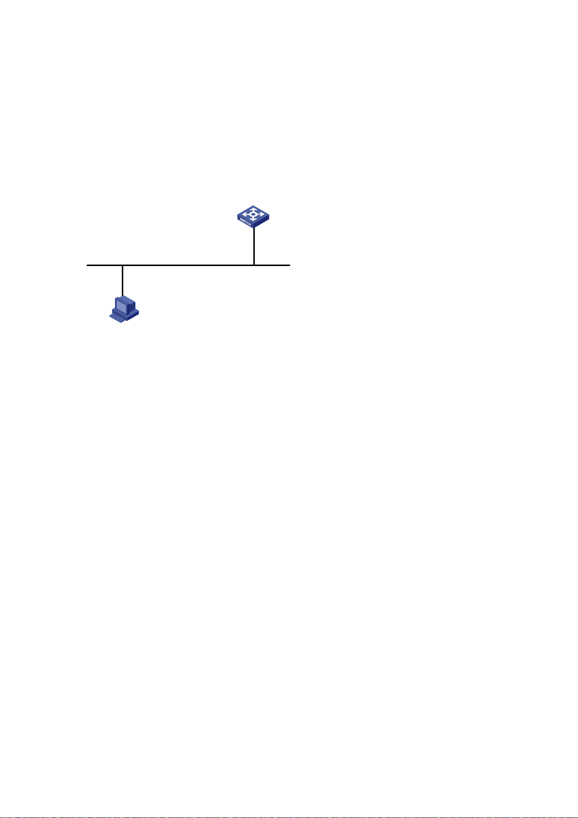
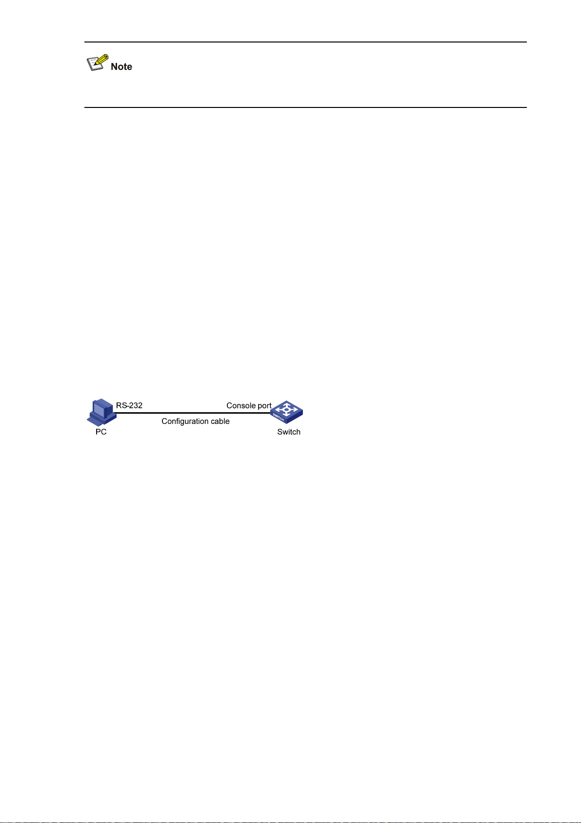
1) Connect the serial port of your PC/terminal to the console port of the switch, as shown in
2-1.
Figure 2-1 Diagram for connecting to the console port of a switch
2-1
Figure
Page 12
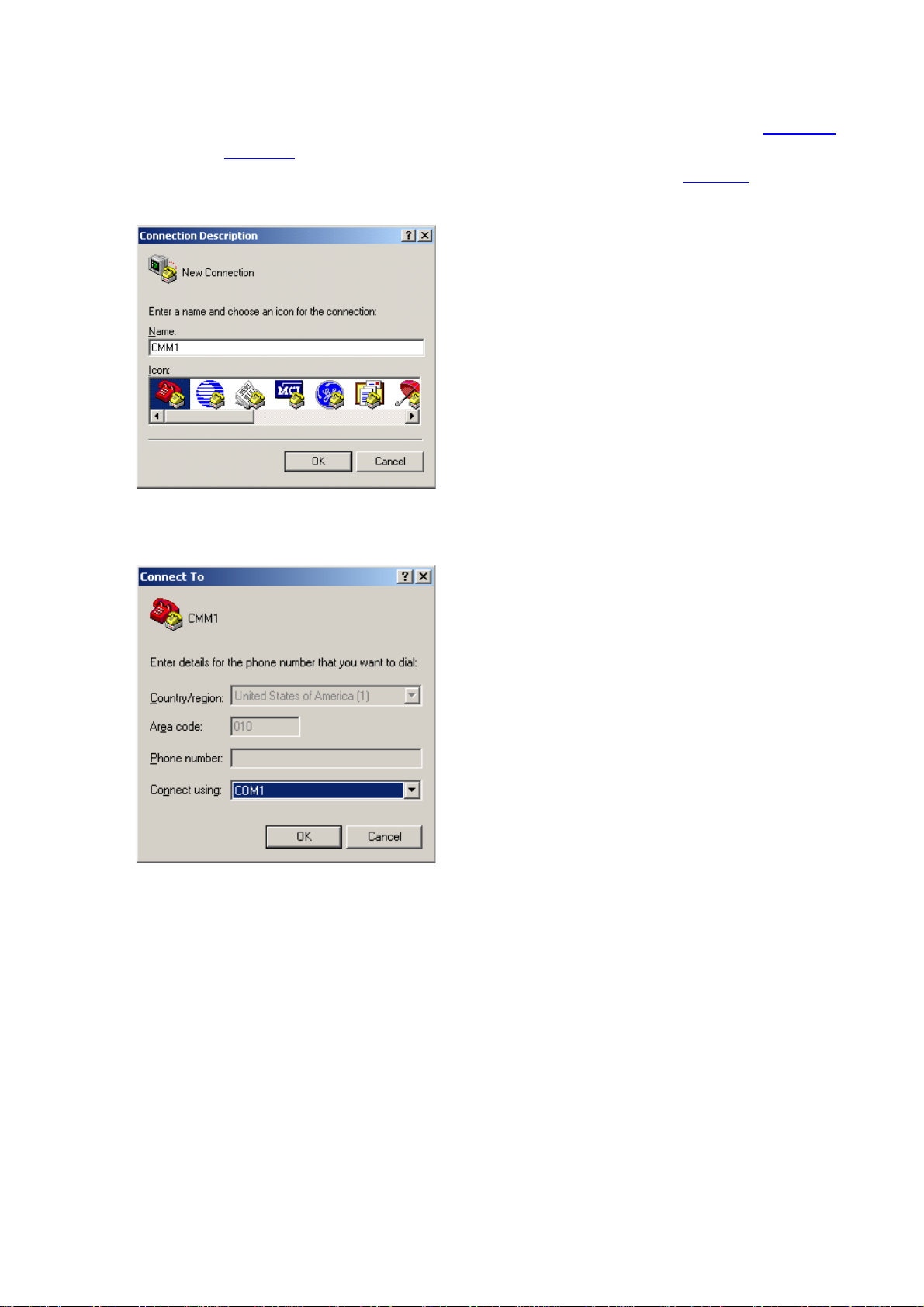
2) If you use a PC to connect to the console port, launch a terminal emulation utility (such as Terminal
in Windows 3.X or HyperTerminal in Windows 9X/Windows 2000/Windows XP. The following
assumes that you are running Windows XP) and perform the configuration shown in
through
the PC and the console port of the switch) are configured as those listed in
Figure 2-4 for the connection to be created. Normally, both sides (that is, the serial port of
Table 2-1.
Figure 2-2
Figure 2-2 Create a connection
Figure 2-3 Specify the port used to establish the connection
2-2
Page 13
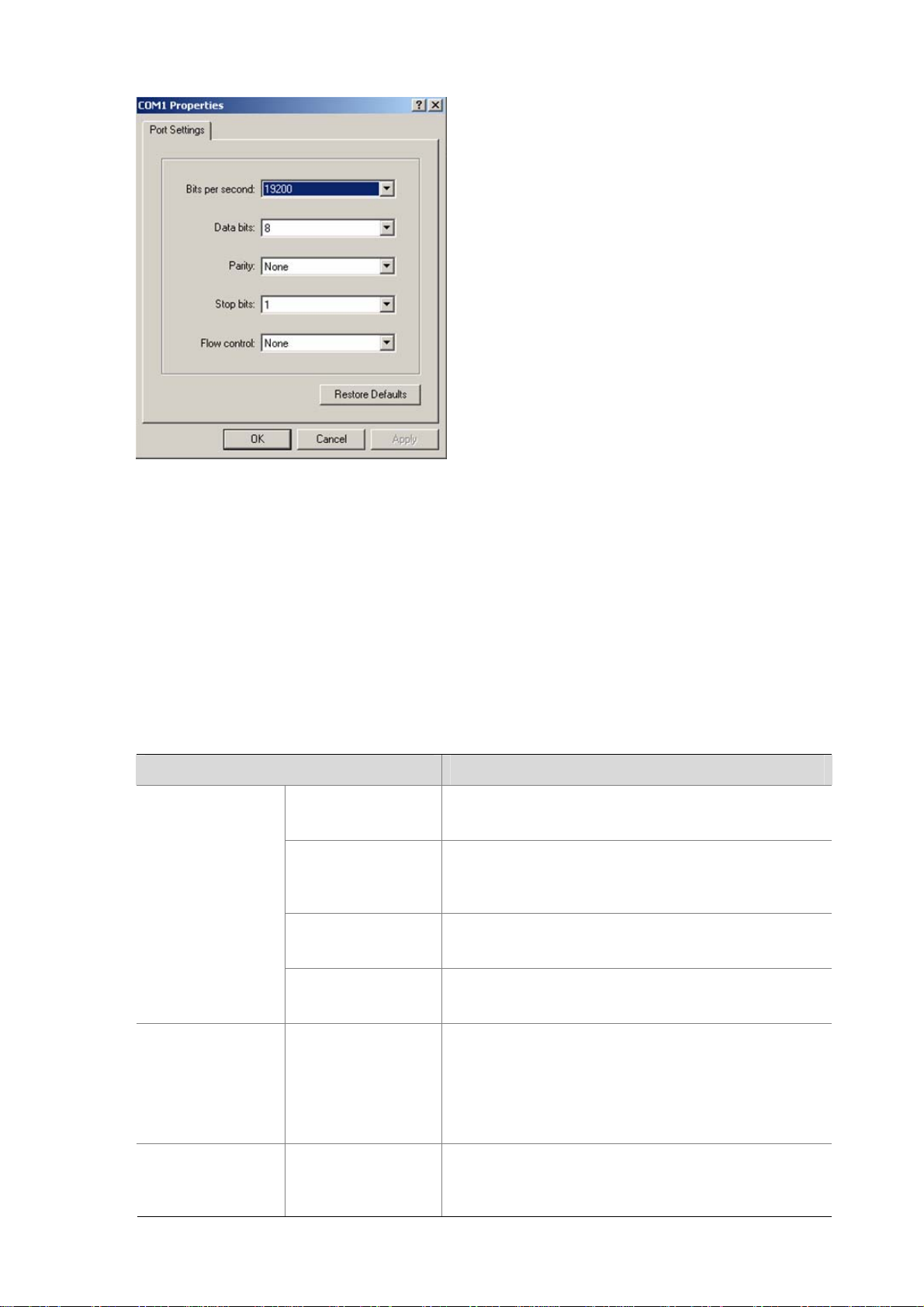
Figure 2-4 Set port parameters
3) Turn on the switch. You will be prompted to press the Enter key if the switch successfully
completes POST (power-on self test). The prompt appears after you press the Enter key.
4) You can then configure the switch or check the information about the switch by executing the
corresponding commands. You can also acquire help by typing the ? character. Refer to related
parts in this manual for information about the commands used for configuring the switch.
Console Port Login Configuration
Common Configuration
Table 2-2 Common configuration of console port login
Configuration Remarks
Baud rate
Check mode
Console port
configuration
Stop bits
Optional
The default baud rate is 19,200 bps.
Optional
By default, the check mode of the console port is set to
“none”, which means no check bit.
Optional
The default stop bits of a console port is 1.
AUX user interface
configuration
Terminal
configuration
Data bits
Configure the
command level
available to the
users logging in to
the AUX user
interface
Make terminal
services available
Optional
The default data bits of a console port is 8.
Optional
By default, commands of level 3 are available to the
users logging in to the AUX user interface.
Optional
By default, terminal services are available in all user
interfaces
2-3
Page 14

Configuration Remarks
Set the maximum
number of lines the
screen can contain
Set history
command buffer
size
Set the timeout time
of a user interface
Optional
By default, the screen can contain up to 24 lines.
Optional
By default, the history command buffer can contain up
to 10 commands.
Optional
The default timeout time is 10 minutes.
The change to console port configuration takes effect immediately, so the connection may be
disconnected when you log in through a console port and then configure this console port. To configure
a console port, you are recommended to log in to the switch in other ways. To log in to a switch through
its console port after you modify the console port settings, you need to modify the corresponding
settings of the terminal emulation utility running on your PC accordingly in the dialog box shown in
Figure 2-4.
Follow these steps to set common configuration of console port login:
To do… Use the command… Remarks
Enter system view
system-view
—
Enter AUX user interface view user-interface aux 0 —
Set the baud
rate
speed speed-value
Optional
The default baud rate of a console
port is 19,200 bps.
Optional
Configure
the console
Set the check
mode
parity { even | none |
odd }
By default, the check mode of a
console port is none, that is, no
check is performed.
port
Set the stop bits stopbits { 1 | 1.5 | 2 }
Optional
The stop bits of a console port is 1.
Optional
Set the databits databits { 7 | 8 }
The default databits of a console port
is 8.
Optional
Configure the command level
available to users logging in to
the user interface
user privilege level level
By default, commands of level 3 are
available to users logging in to the
AUX user interface, and commands
of level 0 are available to users
logging in to the VTY user interface.
Enable terminal services
shell
Optional
By default, terminal services are
available in all user interfaces.
2-4
Page 15
To do… Use the command… Remarks
Optional
By default, the screen can contain up
Set the maximum number of
lines the screen can contain
Set the history command
buffer size
Set the timeout time for the
user interface
screen-length
screen-length
history-command
max-size value
idle-timeout minutes
[ seconds ]
to 24 lines.
You can use the screen-length 0
command to disable the function to
display information in pages.
Optional
The default history command buffer
size is 10, that is, a history command
buffer of a user can store up to 10
commands by default.
Optional
The default timeout time of a user
interface is 10 minutes.
With the timeout time being 10
minutes, the connection to a user
interface is terminated if no operation
is performed in the user interface
within 10 minutes.
You can use the idle-timeout 0
command to disable the timeout
function.
Console Port Login Configurations for Different Authentication Modes
Table 2-3 Console port login configurations for different authentication modes
Authentication
mode
None Set the authentication mode to none
Password
Scheme
Authentication related configuration Remarks
Optional
Console Port
Console Port
Console Port
Set the authentication mode to local password
authentication
Set the password for local authentication
Set the authentication mode to scheme
Specify to perform local authentication or
remote authentication
Set user names and passwords locally or on
AAA Server
Refer to
Login Configuration with
Authentication Mode
Being None
Refer to
Login Configuration with
Authentication Mode
Being Password.
Refer to
Login Configuration with
Authentication Mode
Being Scheme
.
2-5
Page 16

Changes made to the authentication mode for console port login takes effect after you quit the
command-line interface and then log in again.
Console Port Login Configuration with Authentication Mode Being None
Configuration Procedure
Follow these steps to configure console port login with the authentication mode being none:
To do… Use the command… Remarks
Enter system view
Enter AUX user interface view user-interface aux 0 —
Configure not to authenticate
users
Configuration Example
Network requirements
Assume that the switch is configured to allow users to log in through Telnet, and the current user level is
set to the administrator level (level 3). Perform the following configurations for users logging in through
the console port (AUX user interface).
z Do not authenticate the users.
z Commands of level 2 are available to the users logging in to the AUX user interface.
z The baud rate of the console port is 19,200 bps.
z The screen can contain up to 30 lines.
z The history command buffer can contain up to 20 commands.
z The timeout time of the AUX user interface is 6 minutes.
system-view
authentication-mode
none
—
Required
By default, users logging in through
the console port (AUX user interface)
are not authenticated.
2-6
Page 17

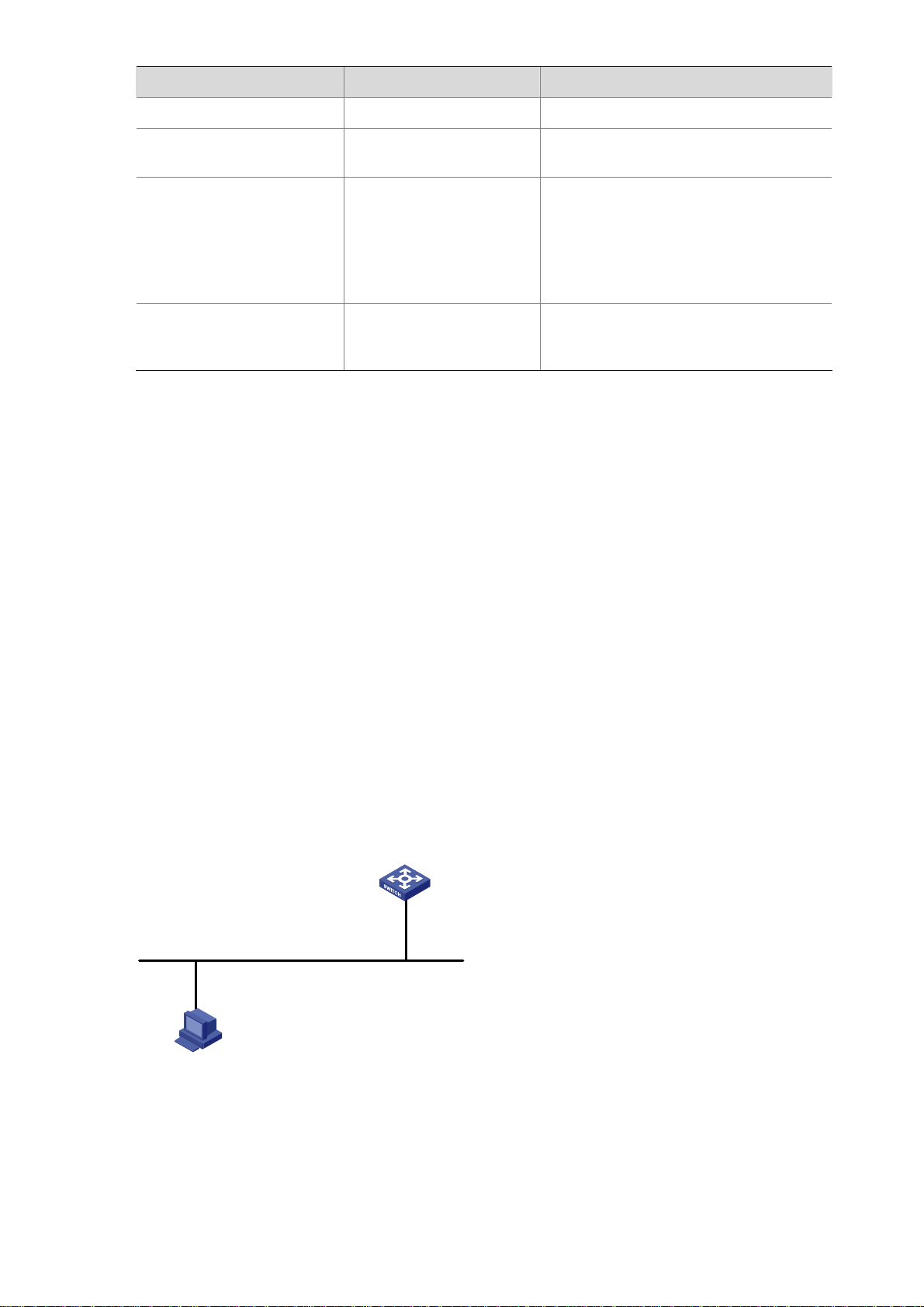
Network diagram
Figure 2-5 Network diagram for AUX user interface configuration (with the authentication mode being
none)
Configuration PC
running Telnet
Configuration procedure
GE1/0/1
Ethernet
# Enter system view.
<Sysname> system-view
# Enter AUX user interface view.
[Sysname] user-interface aux 0
# Specify not to authenticate users logging in through the console port.
[Sysname-ui-aux0] authentication-mode none
# Specify commands of level 2 are available to users logging in to the AUX user interface.
[Sysname-ui-aux0] user privilege level 2
# Set the baud rate of the console port to 19,200 bps.
[Sysname-ui-aux0] speed 19200
# Set the maximum number of lines the screen can contain to 30.
[Sysname-ui-aux0] screen-length 30
# Set the maximum number of commands the history command buffer can store to 20.
[Sysname-ui-aux0] history-command max-size 20
# Set the timeout time of the AUX user interface to 6 minutes.
[Sysname-ui-aux0] idle-timeout 6
After the above configuration, you need to modify the configuration of the terminal emulation utility
running on the PC accordingly in the dialog box shown in
Figure 2-4 to log in to the switch successfully.
Console Port Login Configuration with Authentication Mode Being Password
Configuration Procedure
Follow these steps to configure console port login with the authentication mode being password:
2-7
Page 18
To do… Use the command… Remarks
Enter system view
Enter AUX user interface
view
Configure to authenticate
users using the local
password
Set the local password
Configuration Example
Network requirements
Assume the switch is configured to allow users to log in through Telnet, and the user level is set to the
administrator level (level 3). Perform the following configurations for users logging in through the
console port (AUX user interface).
system-view
—
user-interface aux 0 —
Required
By default, users logging in to a switch
authentication-mode
password
through the console port are not
authenticated; while those logging in
through Modems or Telnet are
authenticated.
set authentication
password { cipher |
Required
simple } password
z Authenticate the users using passwords.
z Set the local password to 123456 (in plain text).
z The commands of level 2 are available to the users.
z The baud rate of the console port is 19,200 bps.
z The screen can contain up to 30 lines.
z The history command buffer can store up to 20 commands.
z The timeout time of the AUX user interface is 6 minutes.
Network diagram
Figure 2-6 Network diagram for AUX user interface configuration (with the authentication mode being
password)
GE1/0/1
Ethernet
Configuration PC
running Telnet
Configuration procedure
# Enter system view.
2-8
Page 19

<Sysname> system-view
# Enter AUX user interface view.
[Sysname] user-interface aux 0
# Specify to authenticate users logging in through the console port using the local password.
[Sysname-ui-aux0] authentication-mode password
# Set the local password to 123456 (in plain text).
[Sysname-ui-aux0] set authentication password simple 123456
# Specify commands of level 2 are available to users logging in to the AUX user interface.
[Sysname-ui-aux0] user privilege level 2
# Set the baud rate of the console port to 19,200 bps.
[Sysname-ui-aux0] speed 19200
# Set the maximum number of lines the screen can contain to 30.
[Sysname-ui-aux0] screen-length 30
# Set the maximum number of commands the history command buffer can store to 20.
[Sysname-ui-aux0] history-command max-size 20
# Set the timeout time of the AUX user interface to 6 minutes.
[Sysname-ui-aux0] idle-timeout 6
After the above configuration, you need to modify the configuration of the terminal emulation utility
running on the PC accordingly in the dialog box shown in
Figure 2-4 to log in to the switch successfully.
Console Port Login Configuration with Authentication Mode Being Scheme
Configuration Procedure
Follow these steps to configure console port login with the authentication mode being scheme:
To do… Use the command… Remarks
Enter system view
system-view
Enter AUX user interface view user-interface aux 0 —
Configure to authenticate
users in the scheme mode
authentication-mode
scheme [ commandauthorization ]
—
Required
The specified AAA scheme
determines what authentication
mode is adopted, local or
RADIUS.
By default, users logging in
through the console port (AUX
user interface) are not
authenticated.
Quit to system view
quit
—
2-9
Page 20
To do… Use the command… Remarks
Enter the
default ISP
domain view
Specify the AAA
scheme to be
applied to the
domain
Configure
the
authenticati
on mode
Quit to system
view
Create a local user (Enter local
user view.)
Set the authentication
password for the local user
domain domain-name
scheme { local | none |
radius-scheme
radius-scheme-name
[ local ] }
quit
local-user user-name
password { simple | cipher }
password
Optional
By default, the local AAA scheme
is applied.
If you specify to apply the local
AAA scheme, you need to
perform the configuration
concerning local user as well.
If you specify to apply a RADIUS
scheme, you need to perform the
following configuration as well:
z Perform RADIUS
configuration on the switch.
(Refer to the AAA part for
more.)
z Configure the user name and
password accordingly on the
AAA server. (Refer to the user
manual of AAA server.)
Required
No local user exists by default.
Required
Specify the service type for
AUX users
service-type terminal [ level
level ]
Required
Note that:
If you configure to authenticate the users in the scheme mode, the command level available to users
logging in to a switch depends on the command level specified in the AAA scheme:
z When the AAA scheme is local authentication, the command level available to users depends on
the service-type terminal [ level level ] command.
z When the AAA scheme is RADIUS authentication, you need to set the corresponding user level on
the RADIUS server.
For the introduction to AAA, RADIUS, refer to the AAA part of this manual.
Configuration Example
Network requirements
Assume the switch is configured to allow users to log in through Telnet, and the user level is set to the
administrator level (level 3). Perform the following configurations for users logging in through the
console port (AUX user interface).
z Configure the local user name as guest.
z Set the authentication password of the local user to 123456 (in plain text).
2-10
Page 21
z Set the service type of the local user to Terminal and the command level to 2.
z Configure to authenticate the users in the scheme mode.
z The baud rate of the console port is 19,200 bps.
z The screen can contain up to 30 lines.
z The history command buffer can store up to 20 commands.
z The timeout time of the AUX user interface is 6 minutes.
Network diagram
Figure 2-7 Network diagram for AUX user interface configuration (with the authentication mode being
scheme)
GE1/0/1
Ethernet
Configuration PC
running Telnet
Configuration procedure
# Enter system view.
<Sysname> system-view
# Create a local user named guest and enter local user view.
[Sysname] local-user guest
# Set the authentication password to 123456 (in plain text).
[Sysname-luser-guest] password simple 123456
# Set the service type to Terminal, Specify commands of level 2 are available to users logging in to the
AUX user interface.
[Sysname-luser-guest] service-type terminal level 2
[Sysname-luser-guest] quit
# Enter AUX user interface view.
[Sysname] user-interface aux 0
# Configure to authenticate users logging in through the console port in the scheme mode.
[Sysname-ui-aux0] authentication-mode scheme
# Set the baud rate of the console port to 19,200 bps.
[Sysname-ui-aux0] speed 19200
# Set the maximum number of lines the screen can contain to 30.
[Sysname-ui-aux0] screen-length 30
# Set the maximum number of commands the history command buffer can store to 20.
2-11
Page 22

[Sysname-ui-aux0] history-command max-size 20
# Set the timeout time of the AUX user interface to 6 minutes.
[Sysname-ui-aux0] idle-timeout 6
After the above configuration, you need to modify the configuration of the terminal emulation utility
running on the PC accordingly in the dialog box shown in
Figure 2-4 to log in to the switch successfully.
2-12
Page 23

3 Logging In Through Telnet
Go to these sections for information you are interested in:
z Introduction
z Telnet Configuration with Authentication Mode Being None
z Telnet Configuration with Authentication Mode Being Password
Introduction
Switch 4500 supports Telnet. You can manage and maintain a switch remotely by Telnetting to the
switch.
To log in to a switch through Telnet, the corresponding configuration is required on both the switch and
the Telnet terminal.
You can also log in to a switch through SSH. SSH is a secure shell added to Telnet. Refer to the SSH
Operation for related information.
Table 3-1 Requirements for Telnetting to a switch
Item Requirement
The IP address is configured for the VLAN of the switch, and the route between
the switch and the Telnet terminal is reachable. (Refer to the IP Address
Switch
Telnet terminal
Telnetting to a switch using IPv6 protocols is similar to Telnetting to a switch using IPv4 protocols. Refer
to the IPv6 Management part for related information.
Configuration – IP Performance Configuration and Routing Protocol parts for
more.)
The authentication mode and other settings are configured. Refer to
Table 3-3.
and
Telnet is running.
The IP address of the VLAN interface of the switch is available.
Table 3-2
Common Configuration to Control Telnet Access
Table 3-2 Common Telnet configuration
Configuration Description
VTY user
interface
configuration
Configure the command
level available to users
logging in to the VTY user
interface
Optional
By default, commands of level 0 are available to
users logging in to a VTY user interface.
3-1
Page 24

Configuration Description
VTY terminal
configuration
Configure the protocols the
user interface supports
Set the commands to be
executed automatically after
a user log in to the user
interface successfully
Make terminal services
available
Set the maximum number of
lines the screen can contain
Set history command buffer
size
Set the timeout time of a user
interface
Optional
By default, Telnet and SSH protocol are
supported.
Optional
By default, no command is executed
automatically after a user logs into the VTY user
interface.
Optional
By default, terminal services are available in all
user interfaces
Optional
By default, the screen can contain up to 24 lines.
Optional
By default, the history command buffer can
contain up to 10 commands.
Optional
The default timeout time is 10 minutes.
Follow these steps to set common telnet configuration:
To do… Use the command… Remarks
Enter system view
Enter one or more VTY user
interface views
system-view
user-interface vty
first-number [ last-number ]
Configure the command level
available to users logging in to
user privilege level level
VTY user interface
Configure the protocols to be
supported by the VTY user
interface
protocol inbound { all |
ssh | telnet }
Set the commands to be
executed automatically after a
user logs in to the user
auto-execute command
text
interface successfully
Enable terminal services
shell
—
—
Optional
By default, commands of level 0
are available to users logging in to
VTY user interfaces.
Optional
By default, both Telnet protocol
and SSH protocol are supported.
Optional
By default, no command is
executed automatically after a
user logs into the VTY user
interface.
Optional
By default, terminal services are
available in all user interfaces.
Set the maximum number of
lines the screen can contain
screen-length
screen-length
3-2
Optional
By default, the screen can contain
up to 24 lines.
You can use the screen-length 0
command to disable the function to
display information in pages.
Page 25
To do… Use the command… Remarks
Optional
The default history command
Set the history command buffer
size
history-command
max-size value
buffer size is 10, that is, the history
command buffer of a user can
store up to 10 commands by
default.
Optional
The default timeout time of a user
interface is 10 minutes.
With the timeout time being 10
Set the timeout time of the VTY
user interface
idle-timeout minutes
[ seconds ]
minutes, the connection to a user
interface is terminated if no
operation is performed in the user
interface within 10 minutes.
You can use the idle-timeout 0
command to disable the timeout
function.
Telnet Configurations for Different Authentication Modes
Table 3-3 Telnet configurations for different authentication modes
Authentication
mode
None Set the authentication mode to none
Password
Scheme
Authentication related configuration Description
Set the authentication mode to local
password authentication
Set the password for local authentication
Set the authentication mode to scheme
Specify to perform local authentication or
remote authentication
Set user names and passwords locally or
on AAA Server
Refer to
Configuration with
Console Port Login
Authentication Mode Being
.
None
Refer to
Configuration with
Console Port Login
Authentication Mode Being
Password
Refer to
Configuration with
.
Console Port Login
Authentication Mode Being
Scheme
.
3-3
Page 26

To improve security and prevent attacks to the unused Sockets, TCP 23 and TCP 22, ports for Telnet
and SSH services respectively, will be enabled or disabled after corresponding configurations.
z If the authentication mode is none, TCP 23 will be enabled, and TCP 22 will be disabled.
z If the authentication mode is password, and the corresponding password has been set, TCP 23
will be enabled, and TCP 22 will be disabled.
z If the authentication mode is scheme, there are three scenarios: when the supported protocol is
specified as telnet, TCP 23 will be enabled; when the supported protocol is specified as ssh, TCP
22 will be enabled; when the supported protocol is specified as all, both the TCP 23 and TCP 22
port will be enabled.
Telnet Configuration with Authentication Mode Being None
Configuration Procedure
Follow these steps to configure Telnet with the authentication mode being none:
To do… Use the command… Remarks
Enter system view
Enter one or more VTY user
interface views
Configure not to authenticate
users logging in to VTY user
interfaces
Note that if you configure not to authenticate the users, the command level available to users logging in
to a switch depends on the user privilege level level command
Configuration Example
Network requirements
Assume current user logins through the console port, and the current user level is set to the
administrator level (level 3). Perform the following configurations for users logging in through VTY 0
using Telnet.
system-view
user-interface vty
first-number [ last-number ]
authentication-mode none
—
—
Required
By default, VTY users are
authenticated after logging in.
z Do not authenticate the users.
z Commands of level 2 are available to the users.
z Telnet protocol is supported.
z The screen can contain up to 30 lines.
z The history command buffer can contain up to 20 commands.
z The timeout time of VTY 0 is 6 minutes.
3-4
Page 27

Network diagram
Figure 3-1 Network diagram for Telnet configuration (with the authentication mode being none)
Configuration procedure
# Enter system view.
<Sysname> system-view
# Enter VTY 0 user interface view.
[Sysname] user-interface vty 0
# Configure not to authenticate Telnet users logging in to VTY 0.
[Sysname-ui-vty0] authentication-mode none
# Specify commands of level 2 are available to users logging in to VTY 0.
[Sysname-ui-vty0] user privilege level 2
# Configure Telnet protocol is supported.
[Sysname-ui-vty0] protocol inbound telnet
# Set the maximum number of lines the screen can contain to 30.
[Sysname-ui-vty0] screen-length 30
# Set the maximum number of commands the history command buffer can store to 20.
[Sysname-ui-vty0] history-command max-size 20
# Set the timeout time to 6 minutes.
[Sysname-ui-vty0] idle-timeout 6
Telnet Configuration with Authentication Mode Being Password
Configuration Procedure
Follow these steps to configure Telnet with the authentication mode being password:
To do… Use the command… Remarks
Enter system view
system-view
—
Enter one or more VTY
user interface views
Configure to authenticate
users logging in to VTY
user interfaces using the
local password
Set the local password
user-interface vty
first-number [ last-number ]
authentication-mode
password
set authentication
password { cipher | simple }
password
3-5
—
Required
Required
Page 28

When the authentication mode is password, the command level available to users logging in to the user
interface is determined by the user privilege level command.
Configuration Example
Network requirements
Assume current user logins through the console port and the current user level is set to the
administrator level (level 3). Perform the following configurations for users logging in to VTY 0 using
Telnet.
z Authenticate users using the local password.
z Set the local password to 123456 (in plain text).
z Commands of level 2 are available to the users.
z Telnet protocol is supported.
z The screen can contain up to 30 lines.
z The history command buffer can contain up to 20 commands.
z The timeout time of VTY 0 is 6 minutes.
Network diagram
Figure 3-2 Network diagram for Telnet configuration (with the authentication mode being password)
Configuration procedure
# Enter system view.
<Sysname> system-view
# Enter VTY 0 user interface view.
[Sysname] user-interface vty 0
# Configure to authenticate users logging in to VTY 0 using the password.
[Sysname-ui-vty0] authentication-mode password
# Set the local password to 123456 (in plain text).
[Sysname-ui-vty0] set authentication password simple 123456
# Specify commands of level 2 are available to users logging in to VTY 0.
[Sysname-ui-vty0] user privilege level 2
# Configure Telnet protocol is supported.
[Sysname-ui-vty0] protocol inbound telnet
# Set the maximum number of lines the screen can contain to 30.
[Sysname-ui-vty0] screen-length 30
# Set the maximum number of commands the history command buffer can store to 20.
[Sysname-ui-vty0] history-command max-size 20
# Set the timeout time to 6 minutes.
[Sysname-ui-vty0] idle-timeout 6
3-6
Page 29

Telnet Configuration with Authentication Mode Being Scheme
Configuration Procedure
Follow these steps to configure Telnet with the authentication mode being scheme:
To do… Use the command… Remarks
Enter system view
Enter one or more VTY user
interface views
Configure to authenticate
users in the scheme mode
Quit to system view
Enter the
default ISP
domain view
Configure the
AAA scheme
Configure
the
to be applied
to the domain
authenticati
on scheme
Quit to
system view
system-view
user-interface vty
first-number [ last-number ]
authentication-mode
scheme [ commandauthorization ]
quit
domain domain-name
scheme { local | none |
radius-scheme
radius-scheme-name
[ local ] }
quit
—
—
Required
The specified AAA scheme
determines what authentication
mode is adopted, local or RADIUS.
Users are authenticated locally by
default.
—
Optional
By default, the local AAA scheme is
applied. If you specify to apply the
local AAA scheme, you need to
perform the configuration
concerning local user as well.
If you specify to apply RADIUS
scheme, you need to perform the
following configuration as well:
z Perform AAA&RADIUS
configuration on the switch.
(Refer to the AAA part for more.)
z Configure the user name and
password accordingly on the
AAA server. (Refer to the user
manual of AAA server.)
Create a local user and enter
local user view
Set the authentication
password for the local user
Specify the service type for
VTY users
local-user user-name
password { simple | cipher }
password
service-type telnet [ level
level ]
No local user exists by default.
Required
Required
Note that:
If you configure to authenticate the users in the scheme mode, the command level available to the users
logging in to the switch depends on the user level defined in the AAA scheme.
z When the AAA scheme is local, the user level depends on the service-type { ftp | lan-access |
{ ssh | telnet | terminal }* [ level level ] } command.
z When the AAA scheme is RADIUS, you need to specify the user level of a user on the
corresponding RADIUS server.
3-7
Page 30
Refer to the AAA part of this manual for information about AAA, RADIUS.
Configuration Example
Network requirements
Assume current user logins through the console port and the user level is set to the administrator level
(level 3). Perform the following configurations for users logging in to VTY 0 using Telnet.
z Configure the local user name as guest.
z Set the authentication password of the local user to 123456 (in plain text).
z Set the service type of VTY users to Telnet and the command level to 2.
z Configure to authenticate users logging in to VTY 0 in scheme mode.
z Only Telnet protocol is supported in VTY 0.
z The screen can contain up to 30 lines.
z The history command buffer can store up to 20 commands.
z The timeout time of VTY 0 is 6 minutes.
Network diagram
Figure 3-3 Network diagram for Telnet configuration (with the authentication mode being scheme)
Configuration procedure
# Enter system view.
<Sysname> system-view
# Create a local user named guest and enter local user view.
[Sysname] local-user guest
# Set the authentication password of the local user to 123456 (in plain text).
[Sysname-luser-guest] password simple 123456
# Set the service type to Telnet, Specify commands of level 2 are available to users logging in to VTY 0..
[Sysname-luser-guest] service-type telnet level 2
[Sysname-luser-guest] quit
# Enter VTY 0 user interface view.
[Sysname] user-interface vty 0
# Configure to authenticate users logging in to VTY 0 in the scheme mode.
[Sysname-ui-vty0] authentication-mode scheme
# Configure Telnet protocol is supported.
[Sysname-ui-vty0] protocol inbound telnet
3-8
Page 31

# Set the maximum number of lines the screen can contain to 30.
[Sysname-ui-vty0] screen-length 30
# Set the maximum number of commands the history command buffer can store to 20.
[Sysname-ui-vty0] history-command max-size 20
# Set the timeout time to 6 minutes.
[Sysname-ui-vty0] idle-timeout 6
Telnetting to a Switch
Telnetting to a Switch from a Terminal
1) Assign an IP address to VLAN-interface 1 of the switch (VLAN 1 is the default VLAN of the switch).
z Connect the serial port of your PC/terminal to the console port of the switch, as shown in Figure 3-4
Figure 3-4 Diagram for establishing connection to a console port
z Launch a terminal emulation utility (such as Terminal in Windows 3.X or HyperTerminal in
Windows 95/Windows 98/Windows NT/Windows 2000/Windows XP) on the PC terminal, with the
baud rate set to 19,200 bps, data bits set to 8, parity check set to none, and flow control set to none.
z Turn on the switch and press Enter as prompted. The prompt appears.
z Perform the following operations in the terminal window to assign IP address 202.38.160.92/24 to
VLAN-interface 1 of the switch.
<Sysname> system-view
[Sysname] interface Vlan-interface 1
[Sysname-Vlan-interface1] ip address 202.38.160.92 255.255.255.0
2) Perform Telnet-related configuration on the switch. Refer to Telnet Configuration with
Authentication Mode Being None
Telnet Configuration with Authentication Mode Being Scheme for more.
and
3) Connect your PC/terminal and the Switch to an Ethernet, as shown in
, Telnet Configuration with Authentication Mode Being Password,
Figure 3-5. Make sure the
port through which the switch is connected to the Ethernet belongs to VLAN 1 and the route
between your PC and VLAN-interface 1 is reachable.
3-9
Page 32

Figure 3-5 Network diagram for Telnet connection establishment
Workstation
WorkstationServer
Ethernet
Configuration PC
running Telnet
Ethernet Switch
Ethernet port
4) Launch Telnet on your PC, with the IP address of VLAN-interface 1 of the switch as the parameter,
as shown in
Figure 3-6.
Figure 3-6 Launch Telnet
5) If the password authentication mode is specified, enter the password when the Telnet window
displays “Login authentication” and prompts for login password. The CLI prompt (such as
<Sysname>) appears if the password is correct. If all VTY user interfaces of the switch are in use,
you will fail to establish the connection and receive the message that says “All user interfaces are
used, please try later!”. A 3Com switch can accommodate up to five Telnet connections at same
time.
6) After successfully Telnetting to the switch, you can configure the switch or display the information
about the switch by executing corresponding commands. You can also type ? at any time for help.
Refer to the relevant parts in this manual for the information about the commands.
z A Telnet connection is terminated if you delete or modify the IP address of the VLAN interface in
the Telnet session.
z By default, commands of level 0 are available to Telnet users authenticated by password. Refer to
the CLI part for information about command hierarchy.
3-10
Page 33

Telnetting to another Switch from the Current Switch
You can Telnet to another switch from the current switch. In this case, the current switch operates as the
client, and the other operates as the server. If the interconnected Ethernet ports of the two switches are
in the same LAN segment, make sure the IP addresses of the two management VLAN interfaces to
which the two Ethernet ports belong to are of the same network segment, or the route between the two
VLAN interfaces is available.
As shown in
Figure 3-7, after Telnetting to a switch (labeled as Telnet client), you can Telnet to another
switch (labeled as Telnet server) by executing the telnet command and then configure it.
Figure 3-7 Network diagram for Telnetting to another switch from the current switch
2) Perform Telnet-related configuration on the switch operating as the Telnet server. Refer to
Configuration with Authentication Mode Being None
Mode Being Password
, and Telnet Configuration with Authentication Mode Being Scheme for
, Telnet Configuration with Authentication
Telnet
more.
3) Telnet to the switch operating as the Telnet client.
4) Execute the following command on the switch operating as the Telnet client:
<Sysname> telnet xxxx
Note that xxxx is the IP address or the host name of the switch operating as the Telnet server. You can
use the ip host to assign a host name to a switch.
1) After successful login, the CLI prompt (such as <Sysname>) appears. If all the VTY user interfaces
of the switch are in use, you will fail to establish the connection and receive the message that says
“All user interfaces are used, please try later!”.
2) After successfully Telnetting to the switch, you can configure the switch or display the information
about the switch by executing corresponding commands. You can also type ? at any time for help.
Refer to the following chapters for the information about the commands.
3-11
Page 34

4 Logging In Using a Modem
Go to these sections for information you are interested in:
z Introduction
z Configuration on the Switch Side
z Modem Connection Establishment
Introduction
The administrator can log in to the console port of a remote switch using a modem through public
switched telephone network (PSTN) if the remote switch is connected to the PSTN through a modem to
configure and maintain the switch remotely. When a network operates improperly or is inaccessible, you
can manage switches in the network remotely in this way.
To log in to a switch in this way, you need to configure the administrator side and the switch properly, as
listed in the following table.
Table 4-1 Requirements for logging in to a switch using a modem
Item Requirement
The PC can communicate with the modem connected to it.
Administrator
side
Switch side
The modem is properly connected to PSTN.
The telephone number of the switch side is available.
The modem is connected to the console port of the switch properly.
The modem is properly configured.
The modem is properly connected to PSTN and a telephone set.
The authentication mode and other related settings are configured on the switch.
Refer to
Table 2-3.
Configuration on the Switch Side
Modem Configuration
Perform the following configuration on the modem directly connected to the switch:
AT&F ----------------------- Restore the factory settings
ATS0=1 ----------------------- Configure to answer automatically after the first ring
AT&D ----------------------- Ignore DTR signal
AT&K0 ----------------------- Disable flow control
AT&R1 ----------------------- Ignore RTS signal
AT&S0 ----------------------- Set DSR to high level by force
ATEQ1&W ----------------------- Disable the Modem from returning command response and the
result, save the changes
4-1
Page 35

You can verify your configuration by executing the AT&V command.
The configuration commands and the output of different modems may differ. Refer to the user manual
of the modem when performing the above configuration.
Switch Configuration
After logging in to a switch through its console port by using a modem, you will enter the AUX user
interface. The corresponding configuration on the switch is the same as those when logging in to the
switch locally through its console port except that:
z When you log in through the console port using a modem, the baud rate of the console port is
usually set to a value lower than the transmission speed of the modem. Otherwise, packets may
get lost.
z Other settings of the console port, such as the check mode, the stop bits, and the data bits, remain
the default.
The configuration on the switch depends on the authentication mode the user is in. Refer to
for the information about authentication mode configuration.
Configuration on switch when the authentication mode is none
Refer to Console Port Login Configuration with Authentication Mode Being None.
Configuration on switch when the authentication mode is password
Refer to Console Port Login Configuration with Authentication Mode Being Password.
Configuration on switch when the authentication mode is scheme
Refer to Console Port Login Configuration with Authentication Mode Being Scheme.
Modem Connection Establishment
1) Before using Modem to log in the switch, perform corresponding configuration for different
authentication modes on the switch. Refer to
Mode Being None
Console Port Login Configuration with Authentication Mode Being Scheme for more.
and
, Console Port Login Configuration with Authentication Mode Being Password,
2) Perform the following configuration to the modem directly connected to the switch. Refer to
Configuration
for related configuration.
3) Connect your PC, the modems, and the switch, as shown in
properly connected to telephone lines.
Console Port Login Configuration with Authentication
Table 2-3
Modem
Figure 4-1. Make sure the modems are
4-2
Page 36

Figure 4-1 Establish the connection by using modems
Modem serial cable
Telephone line
PSTN
Modem
Telephone number
of the romote end:
82882285
Console port
Modem
4) Launch a terminal emulation utility on the PC and set the telephone number to call the modem
directly connected to the switch, as shown in
Figure 4-2 through Figure 4-4. Note that you need to
set the telephone number to that of the modem directly connected to the switch.
Figure 4-2 Create a connection
4-3
Page 37

Figure 4-3 Set the telephone number
Figure 4-4 Call the modem
5) If the password authentication mode is specified, enter the password when prompted. If the
password is correct, the prompt (such as <Sysname>) appears. You can then configure or manage
the switch. You can also enter the character ? at anytime for help. Refer to the related parts in this
manual for information about the configuration commands.
If you perform no AUX user-related configuration on the switch, the commands of level 3 are available
to modem users. Refer to the CLI part for information about command level.
4-4
Page 38

5 CLI Configuration
When configuring CLI, go to these sections for information you are interested in:
z Introduction to the CLI
z Command Hierarchy
z CLI Views
z CLI Features
Introduction to the CLI
A command line interface (CLI) is a user interface to interact with a switch. Through the CLI on a switch,
a user can enter commands to configure the switch and check output information to verify the
configuration. Each 3com switch 4500 provides an easy-to-use CLI and a set of configuration
commands for the convenience of the user to configure and manage the switch.
The CLI on the 3com switch 4500 provides the following features, and so has good manageability and
operability.
z Hierarchical command protection: After users of different levels log in, they can only use
commands at their own, or lower, levels. This prevents users from using unauthorized commands
to configure switches.
z Online help: Users can gain online help at any time by entering a question mark (?).
z Debugging: Abundant and detailed debugging information is provided to help users diagnose and
locate network problems.
z Command history function: This enables users to check the commands that they have lately
executed and re-execute the commands.
z Partial matching of commands: The system will use partially matching method to search for
commands. This allows users to execute a command by entering partially-spelled command
keywords as long as the keywords entered can be uniquely identified by the system.
Command Hierarchy
Command Level and User Privilege Level
To restrict the different users’ access to the device, the system manages the login users and all the
commands by their privilege levels.
All the commands and login users are categorized into four levels, which are visit, monitor, system, and
manage from low to high, and identified respectively by 0 through 3. After users at different privilege
levels log in, they can only use commands at their own, or lower, levels. For example, level 2 users can
only use level 0 through level 2 commands, not level 3 commands.
Command level
Based on user privilege, commands are classified into four levels, which default to:
z Visit level (level 0): Commands at this level are mainly used to diagnose network, and they cannot
be saved in configuration file. For example, ping, tracert and telnet are level 0 commands.
5-1
Page 39

z Monitor level (level 1): Commands at this level are mainly used to maintain the system and
diagnose service faults, and they cannot be saved in configuration file. Such commands include
debugging and terminal.
z System level (level 2): Commands at this level are mainly used to configure services. Commands
concerning routing and network layers are at this level. These commands can be used to provide
network services directly.
z Manage level (level 3): Commands at this level are associated with the basic operation modules
and support modules of the system. These commands provide support for services. Commands
concerning file system, FTP/TFTP/XModem downloading, user management, and level setting are
at this level.
By using the command-privilege level command, the administrator can change the level of a
command in a specific view as required. For details, refer to
User privilege level
Users logged into the switch fall into four user privilege levels, which correspond to the four command
levels respectively. Users at a specific level can only use the commands at the same level or lower
levels.
Modifying the Command Level.
By default, the Console user (a user who logs into the switch through the Console port) is a level-3 user
and can use commands of level 0 through level 3, while Telnet users are level-0 users and can only use
commands of level 0.
You can use the user priv ilege level command to set the default user privilege level for users logging in
through a certain user interface.
If a user logs in using AAA authentication, the user privilege level depends on the configuration of the
AAA scheme. For details, refer to AAA Operation.
Users can switch their user privilege level temporarily without logging out and disconnecting the current
connection; after the switch, users can continue to configure the device without the need of relogin and
reauthentication, but the commands that they can execute have changed. For details, refer to
User Level
.
Modifying the Command Level
Switching
Modifying the command level
All the commands in a view are defaulted to different levels, as shown in Command level. The
administrator can modify the command level based on users’ needs to make users of a lower level use
commands with a higher level or improve device security.
Follow these steps to set the level of a command in a specific view:
5-2
Page 40

To do… Use the command… Remarks
Enter system view
Configure the level of a command in
a specific view
system-view
command-privilege level level view
view command
—
Required
z You are recommended to use the default command level or modify the command level under the
guidance of professional staff; otherwise, the change of command level may bring inconvenience
to your maintenance and operation, or even potential security problem.
z When you change the level of a command with multiple keywords or arguments, you should input
the keywords or arguments one by one in the order they appear in the command syntax. Otherwise,
your configuration will not take effect. The values of the arguments should be within the specified
ranges.
z After you change the level of a command in a certain view to be lower than the default level, change
the level of the command used to enter the view accordingly.
Configuration example
The network administrator (a level 3 user) wants to change some TFTP commands (such as tftp get )
from level 3 to level 0, so that general Telnet users (level 0 users) are able to download files through
TFTP.
# Change the tftp get command in user view (shell) from level 3 to level 0. (Originally, only level 3 users
can change the level of a command.)
<Sysname> system-view
[Sysname] command-privilege level 0 view shell tftp
[Sysname] command-privilege level 0 view shell tftp 192.168.0.1
[Sysname] command-privilege level 0 view shell tftp 192.168.0.1 get
[Sysname] command-privilege level 0 view shell tftp 192.168.0.1 get bootrom.btm
After the above configuration, general Telnet users can use the tftp get command to download file
bootrom.btm and other files from TFTP server 192.168.0.1 and other TFTP servers.
Switching User Level
Overview
Users can switch their user privilege level temporarily without logging out and disconnecting the current
connection; after the switch, users can continue to configure the device without the need of relogin and
reauthentication, but the commands that they can execute have changed.
For example, if the current user privilege level is 3, the user can configure system parameters; after
switching the user privilege level to 0, the user can only execute some simple commands, like ping and
tracert, and only a few display commands.
The switching of user privilege level is temporary, and effective for the current login; after the user relogs
in, the user privilege restores to the original level.
5-3
Page 41

To avoid misoperations, the administrators are recommended to log in to the device by using a lower
privilege level and view device operating parameters, and when they have to maintain the device, they
can switch to a higher level temporarily; when the administrators need to leave for a while or ask
someone else to manage the device temporarily, they can switch to a lower privilege level before they
leave to restrict the operation by others.
The high-to-low user level switching is unlimited. However, the low-to-high user level switching requires
the corresponding authentication.
Complete the following tasks to configure user level switching:
Task Remarks
The administrator configures
the user level switching
authentication policies
The user switches user level
after logging in
Adopting super password authentication for user level switching
Required
Switching to a specific user level Required
Adopting super password authentication for user level switching
With the super password set, you can pass the super password authentication successfully only when
you provide the super password as prompted. If no super password is set, the system prompts
“%Password is not set” when you attempt to switch to a higher user level. In this case, you cannot pass
the super password authentication.
For example, after the administrator configures the super password level 3 simple 123 command,
when users of level 0 through level 2 want to switch to user level 3, they need to input super password
123.
The following table lists the operations to configure super password authentication for user level
switching, which can only be performed by level-3 users (administrators).
Follow these steps to set a password for use level switching:
To do… Use the command… Remarks
Enter system view
system-view
—
Required
Set the super password for
user level switching
super password [ level level ]
{ cipher | simple } password
The configuration will take effect
on all user interfaces.
By default, the super password is
not set.
The super password is for level switching only and is different from the login password.
Switching to a specific user level
Follow these steps to switch to a specific user level:
5-4
Page 42

To do… Use the command… Remarks
Switch to a specified user
level
super [ level ]
Required
Execute this command in user view.
z If no user level is specified in the super password command or the super command, level 3 is
used by default.
z For security purpose, the password entered is not displayed when you switch to another user level.
You will remain at the original user level if you have tried three times but failed to enter the correct
authentication information.
Configuration examples
After a general user telnets to the switch, his/her user level is 0. Now, the network administrator wants to
allow general users to switch to level 3, so that they are able to configure the switch.
z The administrator configures the user level switching authentication policies.
# Set the password used by the current user to switch to level 3.
[Sysname] super password level 3 simple 123
z A VTY 0 user switches its level to level 3 after logging in.
# A VTY 0 user telnets to the switch, and then uses the set password to switch to user level 3.
<Sysname> super 3
Password:
User privilege level is 3, and only those commands can be used
whose level is equal or less than this.
Privilege note: 0-VISIT, 1-MONITOR, 2-SYSTEM, 3-MANAGE
# After configuring the switch, the general user switches back to user level 0.
<Sysname> super 0
User privilege level is 0, and only those commands can be used
whose level is equal or less than this.
Privilege note: 0-VISIT, 1-MONITOR, 2-SYSTEM, 3-MANAGE
CLI Views
CLI views are designed for different configuration tasks. They are both correlated and distinguishing.
For example, once a user logs into a switch successfully, the user enters user view, where the user can
perform some simple operations such as checking the operation status and statistics information of the
switch. After executing the system-view command, the user enters system view, where the user can go
to other views by entering corresponding commands.
Table 5-1 lists the CLI views provided by the 3com switch 4500, operations that can be performed in
different CLI views and the commands used to enter specific CLI views.
5-5
Page 43

Table 5-1 CLI views
View
User view
System view
Ethernet port
view
Aux1/0/0 port
(the console
port) view
Available
operation
Display operation
status and
statistical
information of the
switch
Configure system
parameters
Configure Ethernet
port parameters
The 3com switch
4500 does not
support
configuration on
port Aux1/0/0
Prompt example Enter method Quit method
Execute the
quit command
to log out of the
switch.
Execute the
quit or return
command to
return to user
view.
Execute the
quit command
to return to
system view.
<Sysname>
[Sysname]
100 Mbps Ethernet
port view:
[Sysname-Etherne
t1/0/1]
Enter user view
once logging into
the switch.
Execute the
system-view
command in user
view.
Execute the
interface ethernet
command in
system view.
Execute the
1000 Mbps
Ethernet port view:
[Sysname-Gigabit
Ethernet1/0/25]
Execute the
interface
gigabitethernet
command in
system view.
return
command to
return to user
view.
Execute the
[Sysname-Aux1/0/
0]
interface aux 1/0/0
command in
system view
VLAN view
VLAN
interface view
Loopback
interface view
NULL
interface view
Local user
view
Configure VLAN
parameters
Configure VLAN
interface
parameters,
including the
management
VLAN parameters
Configure loopback
interface
parameters
Configure NULL
interface
parameters
Configure local
user parameters
[Sysname-vlan1]
[Sysname-Vlan-int
erface1]
[Sysname-LoopBa
ck0]
[Sysname-NULL0]
[Sysname-luser-us
er1]
Execute the vlan
command in
system view.
Execute the
interface
Vlan-interface
command in
system view.
Execute the
interface
loopback
command in
system view.
Execute the
interface null
command in
system view.
Execute the
local-user
command in
system view.
User interface
view
Configure user
interface
parameters
[Sysname-ui-aux0]
5-6
Execute the
user-interface
command in
system view.
Page 44

View
FTP client
view
SFTP client
view
MST region
view
Cluster view
Public key
view
Available
operation
Configure FTP
client parameters
Configure SFTP
client parameters
Configure MST
region parameters
Configure cluster
parameters
Configure the RSA
public key for SSH
users
Configure the RSA
or DSA public key
for SSH users
Prompt example Enter method Quit method
Execute the ftp
[ftp]
command in user
view.
Execute the sftp
sftp-client>
command in
system view.
Execute the stp
[Sysname-mst-regi
on]
region-configurati
on command in
system view.
Execute the
[Sysname-cluster]
cluster command
in system view.
Execute the rsa
[Sysname-rsa-publ
ic-key]
[Sysname-peer-pu
blic-key]
peer-public-key
command in
system view.
Execute the
public-key peer
command in
Execute the
peer-public-ke
y end
command to
return to system
view.
system view.
Public key
editing view
RIP view
Routing policy
view
Basic ACL
view
Advanced
ACL view
Layer 2 ACL
view
Edit the RSA public
key for SSH users
Edit the RSA or
DSA public key for
SSH users
Configure RIP
protocol
parameters
Configure routing
policy
Define rules for a
basic ACL (with ID
ranging from 2000
to 2999)
Define rules for an
advanced ACL
(with ID ranging
from 3000 to 3999)
Define rules for an
layer 2 ACL (with
ID ranging from
4000 to 4999)
[Sysname-rsa-keycode]
[Sysname-peer-ke
y-code]
[Sysname-rip]
[Sysname-route-p
olicy]
[Sysname-aclbasic-2000]
[Sysname-acl-adv3000]
[Sysname-acl-ethe
rnetframe-4000]
Execute the
public-key-code
begin command in
public key view.
Execute the rip
command in
system view.
Execute the
route-policy
command in
system view.
Execute the acl
number command
in system view.
Execute the acl
number command
in system view.
Execute the acl
number command
in system view.
Execute the
public-key-cod
e end
command to
return to public
key view.
Execute the
quit command
to return to
system view.
Execute the
return
command to
return to user
view.
User-defined
ACL view
Define rules for a
user-defined ACL
(with ID ranging
from 5000 to 5999)
[Sysname-acl-user
-5000]
5-7
Execute the acl
number command
in system view.
Page 45

View
RADIUS
scheme view
ISP domain
view
Remote-ping
test group
view
PoE profile
view
Detected
group view
QinQ view
Available
operation
Configure RADIUS
scheme
parameters
Configure ISP
domain parameters
Configure
remote-ping test
group parameters
Configure PoE
profile parameters
Configure detected
group parameters
Configure QinQ
parameters
Prompt example Enter method Quit method
[Sysname-radius-1
]
[Sysname-isp-aaa
123.net]
Execute the radius
scheme command
in system view.
Execute the
domain command
in system view.
Execute the
[Sysname-remoteping-a123-a123]
remote-ping
command in
system view.
Execute the
[Sysname-poe-pro
file-a123]
poe-profile
command in
system view.
Execute the
[Sysname-detect-g
roup-1]
detect-group
command in
system view.
Execute the
quit command
to return to
Ethernet port
view.
Execute the
return
command to
return to user
[Sysname-Etherne
t1/0/1-vid-20]
Execute the
vlan-vpn vid
command in
Ethernet port view.
The vlan-vpn
enable command
should be first
executed.
view.
The shortcut key <Ctrl+Z> is equivalent to the return command.
CLI Features
Online Help
When configuring the switch, you can use the online help to get related help information. The CLI
provides two types of online help: complete and partial.
Complete online help
1) Enter a question mark (?) in any view on your terminal to display all the commands available in the
view and their brief descriptions. The following takes user view as an example.
<Sysname> ?
User view commands:
backup Backup current configuration
boot Set boot option
5-8
Page 46

cd Change current directory
clock Specify the system clock
cluster Run cluster command
copy Copy from one file to another
debugging Enable system debugging functions
delete Delete a file
dir List files on a file system
display Display current system information
<Other information is omitted>
2) Enter a command, a space, and a question mark (?).
If the question mark “?” is at a keyword position in the command, all available keywords at the position
and their descriptions will be displayed on your terminal.
<Sysname> clock ?
datetime Specify the time and date
summer-time Configure summer time
timezone Configure time zone
If the question mark “?” is at an argument position in the command, the description of the argument will
be displayed on your terminal.
[Sysname] interface vlan-interface ?
<1-4094> VLAN interface number
If only <cr> is displayed after you enter “?”, it means no parameter is available at the “?” position, and
you can enter and execute the command directly.
[Sysname] interface vlan-interface 1 ?
<cr>
Partial online help
1) Enter a character/string, and then a question mark (?) next to it. All the commands beginning with
the character/string will be displayed on your terminal. For example:
<Sysname> p?
ping
pwd
2) Enter a command, a space, a character/string and a question mark (?) next to it. All the keywords
beginning with the character/string (if available) are displayed on your terminal. For example:
<Sysname> display v?
version
vlan
voice
3) Enter the first several characters of a keyword of a command and then press <Tab>. If there is a
unique keyword beginning with the characters just typed, the unique keyword is displayed in its
complete form. If there are multiple keywords beginning with the characters, you can have them
displayed one by one (in complete form) by pressing <Tab> repeatedly.
Terminal Display
The CLI provides the screen splitting feature to have display output suspended when the screen is full.
When display output pauses, you can perform the following operations as needed (see
Table 5-2).
5-9
Page 47

Table 5-2 Display-related operations
Operation Function
Press <Ctrl+C>
Press any character except <Space>, <Enter>, /,
+, and - when the display output pauses
Press the space key Get to the next page.
Press <Enter> Get to the next line.
Command History
The CLI provides the command history function. You can use the display history-command command
to view a specific number of latest executed commands and execute them again in a convenient way.
By default, the CLI can store up to 10 latest executed commands for each user. You can view the
command history by performing the operations listed in the following table:
Follow these steps to view history commands:
Purpose Operation Remarks
Display the latest
executed history
commands
Stop the display output and execution of the
command.
Stop the display output.
Execute the display
history-command command
This command displays the
command history.
Recall the previous
history command
Recall the next history
command
z The Windows 9x HyperTerminal explains the up and down arrow keys in a different way, and
therefore the two keys are invalid when you access history commands in such an environment.
However, you can use <Ctrl+ P> and <Ctrl+ N> instead to achieve the same purpose.
z When you enter the same command multiple times consecutively, only one history command entry
is created by the command line interface.
Error Prompts
If a command passes the syntax check, it will be successfully executed; otherwise, an error message
will be displayed.
Press the up arrow key or
<Ctrl+P>
Press the down arrow key or
<Ctrl+N>
Table 5-3 lists the common error messages.
This operation recalls the previous
history command (if available).
This operation recalls the next history
command (if available).
5-10
Page 48

Table 5-3 Common error messages
Error message Remarks
The command does not exist.
Unrecognized command
Incomplete command The command entered is incomplete.
Too many parameters The parameters entered are too many.
Ambiguous command The parameters entered are ambiguous.
Wrong parameter A parameter entered is wrong.
found at '^' position An error is found at the '^' position.
Command Edit
The CLI provides basic command edit functions and supports multi-line editing. The maximum number
of characters a command can contain is 254.
Table 5-4 Edit operations
The keyword does not exist.
The parameter type is wrong.
The parameter value is out of range.
Table 5-4 lists the CLI edit operations.
Press… To…
Insert the corresponding character at the cursor position and
A common key
move the cursor one character to the right if the command is
shorter than 254 characters.
Backspace key
Delete the character on the left of the cursor and move the
cursor one character to the left.
Left arrow key or <Ctrl+B> Move the cursor one character to the left.
Right arrow key or <Ctrl+F> Move the cursor one character to the right.
Up arrow key or <Ctrl+P>
Down arrow key or <Ctrl+N>
Display history commands.
Use the partial online help. That is, when you input an
incomplete keyword and press <Tab>, if the input parameter
uniquely identifies a complete keyword, the system
substitutes the complete keyword for the input parameter; if
<Tab>
more than one keywords match the input parameter, you can
display them one by one (in complete form) by pressing
<Tab> repeatedly; if no keyword matches the input
parameter, the system displays your original input on a new
line without any change.
5-11
Page 49

6 Logging In Through the Web-based Network
Management Interface
Go to these sections for information you are interested in:
z Introduction
z Establishing an HTTP Connection
z Configuring the Login Banner
z Enabling/Disabling the WEB Server
Introduction
Switch 4500 has a Web server built in. It enables you to log in to Switch 4500 through a Web browser
and then manage and maintain the switch intuitively by interacting with the built-in Web server.
To log in to Switch 4500 through the built-in Web-based network management interface, you need to
perform the related configuration on both the switch and the PC operating as the network management
terminal.
Table 6-1 Requirements for logging in to a switch through the Web-based network management
system
Item Requirement
The VLAN interface of the switch is assigned an IP address, and the route
between the switch and the Web network management terminal is reachable.
Switch
the network
management
terminal
(Refer to the IP Address Configuration – IP Performance Configuration and
Routing Protocol parts for related information.)
The user name and password for logging in to the Web-based network
management system are configured.
IE is available. PC operating as
The IP address of the VLAN interface of the switch, the user name, and the
password are available.
Establishing an HTTP Connection
1) Assign an IP address to VLAN-interface 1 of the switch (VLAN 1 is the default VLAN of the switch).
Telnetting to a Switch from a Terminal for related information.
See
2) Configure the user name and the password on the switch for the Web network management user to
log in.
# Create a Web user account, setting both the user name and the password to admin and the user level
to 3.
<Sysname> system-view
[Sysname] local-user admin
[Sysname-luser-admin] service-type telnet level 3
[Sysname-luser-admin] password simple admin
6-1
Page 50

3) Establish an HTTP connection between your PC and the switch, as shown in Figure 6-1.
Figure 6-1 Establish an HTTP connection between your PC and the switch
4) Log in to the switch through IE. Launch IE on the Web-based network management terminal (your
PC) and enter the IP address of the management VLAN interface of the switch in the address bar.
(Make sure the route between the Web-based network management terminal and the switch is
available.)
5) When the login authentication interface (as shown in
the password configured in step 2 and click <Login> to bring up the main page of the Web-based
network management system.
Figure 6-2 The login page of the Web-based network management system
Figure 6-2) appears, enter the user name and
Configuring the Login Banner
Configuration Procedure
If a login banner is configured with the header command, when a user logs in through Web, the banner
page is displayed before the user login authentication page. The contents of the banner page are the
login banner information configured with the header command. Then, by clicking <Continue> on the
banner page, the user can enter the user login authentication page, and enter the main page of the
Web-based network management system after passing the authentication. If no login banner is
configured by the header command, a user logging in through Web directly enters the user login
authentication page.
Follow these steps to configure the login banner:
To do… Use the command… Remarks
Enter system view
Configure the banner to be
displayed when a user logs in
through Web
system-view
header login text
—
Required
By default, no login banner is
configured.
6-2
Page 51

Configuration Example
Network requirements
z A user logs in to the switch through Web.
z The banner page is desired when a user logs into the switch.
Network diagram
Figure 6-3 Network diagram for login banner configuration
Configuration Procedure
# Enter system view.
<Sysname> system-view
# Configure the banner Welcome to be displayed when a user logs into the switch through Web.
[Sysname] header login %Welcome%
Assume that a route is available between the user terminal (the PC) and the switch. After the
above-mentioned configuration, if you enter the IP address of the switch in the address bar of the
browser running on the user terminal and press <Enter>, the browser will display the banner page, as
shown in
Figure 6-4.
Figure 6-4 Banner page displayed when a user logs in to the switch through Web
Click <Continue> to enter user login authentication page. You will enter the main page of the
Web-based network management system if the authentication succeeds.
Enabling/Disabling the WEB Server
Follow these steps to enable/Disable the WEB Server:
6-3
Page 52

To do… Use the command… Remarks
Enter system view
system-view
—
Required
Enable the Web server
ip http shutdown
By default, the Web server is
enabled.
Disable the Web server
undo ip http shutdown
Required
To improve security and prevent attack to the unused Sockets, TCP 80 port (which is for HTTP service)
is enabled/disabled after the corresponding configuration.
z Enabling the Web server (by using the undo ip http shutdown command) opens TCP 80 port.
z Disabling the Web server (by using the ip http shutdown command) closes TCP 80 port.
6-4
Page 53

7 Logging In Through NMS
Go to these sections for information you are interested in:
z Introduction
z Connection Establishment Using NMS
Introduction
You can also log in to a switch through a Network Management Station (NMS), and then configure and
manage the switch through the agent software on the switch. Simple Network Management Protocol
(SNMP) is applied between the NMS and the agent. Refer to the SNMP-RMON part for related
information.
To log in to a switch through an NMS, you need to perform related configuration on both the NMS and
the switch.
Table 7-1 Requirements for logging in to a switch through an NMS
Item Requirement
The IP address of the VLAN interface of the switch is configured. The route between
the NMS and the switch is reachable. (Refer to the IP Address Configuration – IP
Switch
NMS
Performance Configuration and Routing Protocol parts for related information.)
The basic SNMP functions are configured. (Refer to the SNMP-RMON part for
related information.)
The NMS is properly configured. (Refer to the user manual of your NMS for related
information.)
Connection Establishment Using NMS
Figure 7-1 Network diagram for logging in through an NMS
Switch
Network
NMS
7-1
Page 54

8 Configuring Source IP Address for Telnet Service
Packets
Go to these sections for information you are interested in:
z Overview
z Configuring Source IP Address for Telnet Service Packets
z Displaying Source IP Address Configuration
Overview
You can configure source IP address or source interface for the Telnet server and Telnet client. This
provides a way to manage services and enhances security.
The source IP address specified for Telnet service packets is the IP address of an Loopback interface or
VLAN interface. After you specify the IP address of a virtual Loopback interface or an unused VLAN
interface as the source IP address of Telnet service packets, the IP address is used as the source IP
address no matter which interface of the switch is used to transmit packets between the Telnet client
and the Telnet server. This conceals the IP address of the actual interface used. As a result, external
attacks are guarded and the security is improved. On the other hand, you can configure the Telnet
server to accept only Telnet service packets with specific source IP addresses to make sure specific
users can log into the switch.
Configuring Source IP Address for Telnet Service Packets
This feature can be configured in either user view or system view. The configuration performed in user
view takes effect for only the current session, while the configuration performed in system view takes
effect for all the following sessions.
Configuration in user view
Table 8-1 Configure a source IP address for service packets in user view
Operation Command Description
Specify a source IP address for
the Telnet client
telnet remote-server source-ip ip-address
Optional
Specify a source interface for the
Telnet client
Configuration in system view
Table 8-2 Configure a source IP address for service packets in system view
Operation Command Description
Specify a source IP address for
Telnet server
telnet remote-server source-interface
interface-type interface-number
telnet-server source-ip ip-address
8-1
Optional
Optional
Page 55

Operation Command Description
Specify a source interface for
Telnet server
Specify source IP address for
Telnet client
Specify a source interface for
Telnet client
telnet-server source-interface
interface-type interface-number
telnet source-ip ip-address
telnet source-interface interface-type
interface-number
To perform the configurations listed in Table 8-1 and Table 8-2, make sure that:
z The IP address specified is that of the local device.
z The interface specified exists.
z If a source IP address (or source interface) is specified, you need to make sure that the route
between the IP addresses (or interface) of both sides is reachable.
Displaying Source IP Address Configuration
Optional
Optional
Optional
Execute the display command in any view to display the operation state after the above configurations.
You can verify the configuration effect through the displayed information.
Table 8-3 Display the source IP address configuration
Operation Command Description
Display the source IP address
configured for the Telnet client
Display the source IP address
configured for the Telnet server
display telnet source-ip
display telnet-server
source-ip
You can execute the two
commands in any view.
8-2
Page 56

9 User Control
Go to these sections for information you are interested in:
z Introduction
z Controlling Telnet Users
z Controlling Network Management Users by Source IP Addresses
z Controlling Web Users by Source IP Address
Refer to the ACL part for information about ACL.
Introduction
You can control users logging in through Telnet, SNMP and WEB by defining Access Control List (ACL),
as listed in
Table 9-1 Ways to control different types of login users
Login mode Control method Implementation Related section
Telnet
SNMP
WEB
Table 9-1.
By source IP address Through basic ACL
By source and
destination IP address
By source MAC
address
By source IP
addresses
By source IP
addresses
Disconnect Web
users by force
Through advanced
ACL
Through Layer 2 ACL
Through basic ACL
Through basic ACL
By executing
commands in CLI
Controlling Telnet Users
Controlling Network
Management Users by
Source IP Addresses
Controlling Web Users by
Source IP Address
Logging Out a Web User
Controlling Telnet Users
Introduction
The controlling policy against Telnet users’ access to VTY user interfaces is determined by referencing
ACL. For the introduction to ACL, refer to the ACL part of this manual.
9-1
Page 57

z If no ACL is configured on the VTY user interface, users are not controlled when establishing a
Telnet connection using this user interface.
z If an ACL is configured on the VTY user interface, there will be two possibilities: if the packets for
establishing a Telnet connection match the ACL rule configured on the VTY user interface, the
connection will be permitted or denied according to the ACL rule; if not, the connection will be
denied directly.
Controlling Telnet Users by ACL
Controlling Telnet users by ACL is achieved by the following two ways:
z inbound: Applies the ACL to the users Telnetting to the local switch through the VTY user
interface.
z outbound: Applies the ACL to the users Telnetting to other devices through the current user
interface. This keyword is unavailable to Layer 2 ACLs.
You can configure the following three types of ACLs as needed:
Table 9-2 ACL categories
Category ACL number Matching criteria
Basic ACL 2000 to 2999 Source IP address
Advanced ACL 3000 to 3999
Source IP address and
destination IP address
Layer 2 ACL 4000 to 4999 Source MAC address
Source and destination in this manual refer to a Telnet client and a Telnet server respectively.
z If the inbound keyword is specified, the Telnet client is the user telnetting to the local switch and
the Telnet server is the local switch.
z If the outbound keyword is specified, the Telnet client is the local switch, and the Telnet server is
another device to which the user is telnetting.
Follow these steps to control Telnet users by ACL:
To do… Use the command… Remarks
Enter system view
system-view
—
Create a basic ACL or enter
basic ACL view
Define rules for the ACL
Quit to system view
Enter user interface view
acl number acl-number
[ match-order { auto |
config } ]
rule [ rule-id ] { deny |
permit } [ rule-string ]
quit
user-interface [ type ]
first-number [ last-number ]
9-2
As for the acl number command, the
config keyword is specified by
default.
Required
—
—
Page 58

To do… Use the command… Remarks
Apply a
basic or
advanced
Apply an
ACL to
control
ACL to
control
Telnet users
Telnet users
by ACL
Apply a
Layer 2 ACL
to control
Telnet users
Configuration Example
Network requirements
Only the Telnet users sourced from the IP address of 10.110.100.52 are permitted to access the switch.
Network diagram
Figure 9-1 Network diagram for controlling Telnet users using ACLs
acl acl-number { inbound |
outbound }
acl acl-number inbound
Required
Use either command
z The inbound keyword specifies to
filter the users trying to Telnet to
the current switch.
z The outbound keyword specifies
to filter users trying to Telnet to
other switches from the current
switch.
10.110.100.46
Host A
IP network
Switch
Host B
10.110.100.52
Configuration procedure
# Define a basic ACL.
<Sysname> system-view
[Sysname] acl number 2000
[Sysname-acl-basic-2000] rule 1 permit source 10.110.100.52 0
[Sysname-acl-basic-2000] quit
# Apply the ACL.
[Sysname] user-interface vty 0 4
[Sysname-ui-vty0-4] acl 2000 inbound
Controlling Network Management Users by Source IP Addresses
You can manage Switch 4500 through network management software. Network management users can
access switches through SNMP.
You need to perform the following two operations to control network management users by source IP
addresses.
9-3
Page 59

z Defining an ACL
z Applying the ACL to control users accessing the switch through SNMP
To control whether an NMS can manage the switch, you can use this function.
Prerequisites
The controlling policy against network management users is determined, including the source IP
addresses to be controlled and the controlling actions (permitting or denying).
Controlling Network Management Users by Source IP Addresses
Controlling network management users by source IP addresses is achieved by applying basic ACLs,
which are numbered from 2000 to 2999.
Follow these steps to control network management users by source IP addresses:
To do… Use the command… Remarks
Enter system view
system-view
—
As for the acl number
Create a basic ACL or
enter basic ACL view
acl number acl-number [ match-order
{ auto | config } ]
command, the config
keyword is specified by
default.
Define rules for the ACL rule [ rule-id ] { deny | permit } [ rule-string ] Required
Quit to system view
Apply the ACL while
configuring the SNMP
community name
quit
snmp-agent community { read | write }
community-name [ acl acl-number |
mib-view view-name ]*
—
snmp-agent group { v1 | v2c }
Apply the ACL while
configuring the SNMP
group name
Apply the ACL while
configuring the SNMP
user name
group-name [ read-view read-view ]
[ write-view write-view ] [ notify-view
notify-view ] [ acl acl-number ]
snmp-agent group v3 group-name
[ authentication | privacy ] [ read-view
read-view ] [ write-view write-view ]
[ notify-view notify-view ] [ acl acl-number ]
snmp-agent usm-user { v1 | v2c }
user-name group-name [ acl acl-number ]
snmp-agent usm-user v3 user-name
group-name [ [ cipher ]
authentication-mode { md5 | sha }
auth-password [ privacy-mode { des56 |
Required
According to the SNMP
version and configuration
customs of NMS users,
you can reference an ACL
when configuring
community name, group
name or username. For
the detailed configuration,
refer to SNMP-RMON for
more.
aes128 } priv-password ] ] [ acl
acl-number ]
Configuration Example
Network requirements
Only SNMP users sourced from the IP addresses of 10.110.100.52 are permitted to log in to the switch.
9-4
Page 60

Network diagram
Figure 9-2 Network diagram for controlling SNMP users using ACLs
10.110.100.46
Host A
Host B
10.110.100.52
Configuration procedure
# Define a basic ACL.
<Sysname> system-view
[Sysname] acl number 2000
[Sysname-acl-basic-2000] rule 1 permit source 10.110.100.52 0
[Sysname-acl-basic-2000] quit
IP network
Switch
# Apply the ACL to only permit SNMP users sourced from the IP addresses of 10.110.100.52 to access
the switch.
[Sysname] snmp-agent community read aaa acl 2000
[Sysname] snmp-agent group v2c groupa acl 2000
[Sysname] snmp-agent usm-user v2c usera groupa acl 2000
Controlling Web Users by Source IP Address
You can manage Switch 4500 remotely through Web. Web users can access a switch through HTTP
connections.
You need to perform the following two operations to control Web users by source IP addresses.
z Defining an ACL
z Applying the ACL to control Web users
To control whether a Web user can manage the switch, you can use this function.
Prerequisites
The controlling policy against Web users is determined, including the source IP addresses to be
controlled and the controlling actions (permitting or denying).
Controlling Web Users by Source IP Addresses
Controlling Web users by source IP addresses is achieved by applying basic ACLs, which are
numbered from 2000 to 2999.
Follow these steps to control Web users by source IP addresses:
9-5
Page 61

To do… Use the command… Remarks
Enter system view
Create a basic ACL or enter
basic ACL view
Define rules for the ACL
Quit to system view
Apply the ACL to control
Web users
Logging Out a Web User
The administrator can log out a Web user using the related command.
Follow the step below to log out a Web user:
To do… Use the command… Remarks
Log out a Web user
system-view
acl number acl-number
[ match-order { config | auto } ]
rule [ rule-id ] { deny | permit }
[ rule-string ]
quit
ip http acl acl-number
free web-users { all | user-id user-id |
user-name user-name }
—
As for the acl number
command, the config keyword
is specified by default.
Required
—
Optional
By default, no ACL is applied
for Web users.
Required
Available in user view
Configuration Example
Network requirements
Only the Web users sourced from the IP address of 10.110.100.52 are permitted to access the switch.
Network diagram
Figure 9-3 Network diagram for controlling Web users using ACLs
10.110.100.46
Host A
IP network
Host B
10.110.100.52
Switch
Configuration procedure
# Define a basic ACL.
<Sysname> system-view
[Sysname] acl number 2030
[Sysname-acl-basic-2030] rule 1 permit source 10.110.100.52 0
9-6
Page 62

[Sysname-acl-basic-2030] quit
# Apply ACL 2030 to only permit the Web users sourced from the IP address of 10.110.100.52 to access
the switch.
[Sysname] ip http acl 2030
9-7
Page 63

Table of Contents
1 Configuration File Management···············································································································1-1
Introduction to Configuration File ············································································································1-1
Configuration Task List ···························································································································1-2
Saving the Current Configuration ····································································································1-2
Erasing the Startup Configuration File ····························································································1-3
Specifying a Configuration File for Next Startup ·············································································1-4
Displaying Switch Configuration······································································································1-5
i
Page 64

1 Configuration File Management
When configuring configuration file management, go to these sections for information you are
interested in:
z Introduction to Configuration File
z Configuration Task List
Introduction to Configuration File
A configuration file records and stores user configurations performed to a switch. It also enables users
to check switch configurations easily.
Types of configuration
The configuration of a switch falls into two types:
z Saved configuration, a configuration file used for initialization. If this file does not exist, the switch
starts up without loading any configuration file.
z Current configuration, which refers to the user’s configuration during the operation of a switch. This
configuration is stored in Dynamic Random-Access Memory (DRAM). It is removed when
rebooting.
Format of configuration file
Configuration files are saved as text files for ease of reading. They:
z Save configuration in the form of commands.
z Save only non-default configuration settings.
z The commands are grouped into sections by command view. The commands that are of the same
command view are grouped into one section. Sections are separated by comment lines. (A line is a
comment line if it starts with the character #.)
z The sections are listed in this order: system configuration section, logical interface configuration
section, physical port configuration section, routing protocol configuration section, user interface
configuration, and so on.
z End with a return.
The operating interface provided by the configuration file management function is user-friendly. With it,
you can easily manage your configuration files.
Main/backup attribute of the configuration file
Main and backup indicate the main and backup attribute of the configuration file respectively. A main
configuration file and a backup configuration file can coexist on the switch. As such, when the main
configuration file is missing or damaged, the backup file can be used instead. This increases the safety
and reliability of the file system compared with the switch that only support one configuration file. You
can configure a file to have both main and backup attribute, but only one file of either main or backup
attribute is allowed on a switch.
The following three situations are concerned with the main/backup attributes:
1-1
Page 65

z When saving the current configuration, you can specify the file to be a main or backup or normal
configuration file.
z When removing a configuration file from a switch, you can specify to remove the main or backup
configuration file. Or, if it is a file having both main and backup attribute, you can specify to erase
the main or backup attribute of the file.
z When setting the configuration file for next startup, you can specify to use the main or backup
configuration file.
Startup with the configuration file
When booting, the system chooses the configuration files following the rules below:
1) If the main configuration file exists, the switch initializes with this configuration.
2) If the main configuration file does not exist but the backup configuration file exists, the switch
initializes with the backup configuration.
3) If neither the main nor the backup configuration file exists, but the default configuration file
config.def exists, the switch initializes with the default configuration file; if the default configuration
file does not exist, the switch starts up without loading the configuration file.
Configuration Task List
Complete these tasks to configure configuration file management:
Task Remarks
Saving the Current Configuration Optional
Erasing the Startup Configuration File Optional
Specifying a Configuration File for Next Startup Optional
Saving the Current Configuration
You can modify the configuration on your switch at the command line interface (CLI). To use the
modified configuration for your subsequent startups, you must save it (using the save command) as a
configuration file.
Use the following command to save current configuration:
To do… Use the command… Remarks
Save current configuration
save [ cfgfile | [ safely ]
[ backup | main ] ]
Required
Available in any view
Modes in saving the configuration
z Fast saving mode. This is the mode when you use the save command without the safely keyword.
The mode saves the file quicker but is likely to lose the original configuration file if the switch
reboots or the power fails during the process.
z Safe mode. This is the mode when you use the save command with the safely keyword. The mode
saves the file slower but can retain the original configuration file in the switch even if the switch
reboots or the power fails during the process.
1-2
Page 66

When you use the save safely command to save the configuration file, if the switch reboots or the
power fails during the saving process, the switch initializes itself in the following two conditions when it
starts up next time:
z If a configuration file with the extension .cfg exists in the Flash, the switch uses the configuration
file to initialize itself when it starts up next time.
z If there is no .cfg configuration file in the Flash, but there is a configuration file with the
extension .cfgbak (backup configuration file containing the original configuration information)
or/and a configuration file with the extension .cfgtmp (temporary configuration file containing the
current configuration information) in the Flash, you can change the extension .cfgbak or .cfgtmp
to .cfg using the rename command. The switch will use the renamed configuration file to initialize
itself when it starts up next time.
For details of the rename command, refer to the File System Management part of the manual.
Three attributes of the configuration file
z Main attribute. When you use the save [ [ safely ] [ main ] ] command to save the current
configuration, the configuration file you get has main attribute. If this configuration file already
exists and has backup attribute, the file will have both main and backup attributes after execution of
this command. If the filename you entered is different from that existing in the system, this
command will erase its main attribute to allow only one main attribute configuration file in the
switch.
z Backup attribute. When you use the save [ safely ] backup command to save the current
configuration, the configuration file you get has backup attribute. If this configuration file already
exists and has main attribute, the file will have both main and backup attributes after execution of
this command. If the filename you entered is different from that existing in the system, this
command will erase its backup attribute to allow only one backup attribute configuration file in the
switch.
z Normal attribute. When you use the save cfgfile command to save the current configuration, the
configuration file you get has normal attribute if it is not an existing file. Otherwise, the attribute is
dependent on the original attribute of the file.
z It is recommended to adopt the fast saving mode in the conditions of stable power and adopt the
safe mode in the conditions of unstable power or remote maintenance.
z If you use the save command after a fabric is formed on the switch, the units in the fabric save their
own startup configuration files automatically.
z The extension name of the configuration file must be .cfg.
Erasing the Startup Configuration File
You can clear the configuration files saved on the switch through commands.
Use the following command to erase the configuration file:
1-3
Page 67

To do… Use the command… Remarks
Erase the startup configuration
file from the storage switch
reset saved-configuration
[ backup | main ]
Required
Available in user view
You may need to erase the configuration file for one of these reasons:
z After you upgrade software, the old configuration file does not match the new software.
z The startup configuration file is corrupted or not the one you needed.
The following two situations exist:
z While the reset saved-configuration [ main ] command erases the configuration file with main
attribute, it only erases the main attribute of a configuration file having both main and backup
attribute.
z While the reset saved-configuration backup command erases the configuration file with backup
attribute, it only erases the backup attribute of a configuration file having both main and backup
attribute.
This command will permanently delete the configuration file from the switch.
Specifying a Configuration File for Next Startup
Use the following command to specify a configuration file for next startup:
To do… Use the command… Remarks
Specify a configuration file for
next startup
You can specify a configuration file to be used for the next startup and configure the main/backup
attribute for the configuration file.
Assigning main attribute to the startup configuration file
z If you save the current configuration to the main configuration file, the system will automatically set
the file as the main startup configuration file.
z You can also use the startup saved-configuration cfgfile [ main ] command to set the file as main
startup configuration file.
startup saved-configuration
cfgfile [ backup | main ]
Required
Available in user view
Assigning backup attribute to the startup configuration file
z If you save the current configuration to the backup configuration file, the system will automatically
set the file as the backup startup configuration file.
z You can also use the startup saved-configuration cfgfile backup command to set the file as
backup startup configuration file.
1-4
Page 68

The configuration file must use .cfg as its extension name and the startup configuration file must be
saved at the root directory of the switch.
Displaying Switch Configuration
To do… Use the command… Remarks
Display the initial configuration
file saved in the Flash of a
switch
Display the configuration file
used for this and next startup
Display the current VLAN
configuration of the switch
Display the validated
configuration in current view
Display current configuration
display saved-configuration [ unit unit-id ]
[ by-linenum ]
display startup [ unit unit-id ]
display current-configuration vlan
[ vlan-id ] [ by-linenum ]
display this [ by-linenum ]
display current-configuration
[ configuration [ configuration-type ] |
interface [ interface-type ]
[ interface-number ] ] [ by-linenum ] [ | { begin
| exclude | include } regular-expression ]
Available in any
view.
1-5
Page 69

Table of Contents
1 VLAN Overview··········································································································································1-1
VLAN Overview·······································································································································1-1
Introduction to VLAN ·······················································································································1-1
Advantages of VLANs ·····················································································································1-2
VLAN Principles·······························································································································1-2
VLAN Interface ································································································································1-4
VLAN Classification ·························································································································1-4
Port-Based VLAN····································································································································1-4
Link Types of Ethernet Ports ···········································································································1-4
Assigning an Ethernet Port to Specified VLANs ·············································································1-5
Configuring the Default VLAN ID for a Port·····················································································1-5
2 VLAN Configuration ··································································································································2-1
VLAN Configuration ································································································································2-1
VLAN Configuration Task List ·········································································································2-1
Basic VLAN Configuration···············································································································2-1
Basic VLAN Interface Configuration································································································2-2
Displaying VLAN Configuration ·······································································································2-3
Configuring a Port-Based VLAN ·············································································································2-3
Port-Based VLAN Configuration Task List ······················································································2-3
Configuring the Link Type of an Ethernet Port ················································································2-3
Assigning an Ethernet Port to a VLAN ····························································································2-4
Configuring the Default VLAN for a Port ·························································································2-5
Displaying and Maintaining Port-Based VLAN················································································2-5
Port-Based VLAN Configuration Example·······················································································2-5
i
Page 70

1 VLAN Overview
This chapter covers these topics:
z VLAN Overview
z Port-Based VLAN
VLAN Overview
Introduction to VLAN
The traditional Ethernet is a broadcast network, where all hosts are in the same broadcast domain and
connected with each other through hubs or switches. Hubs and switches, which are the basic network
connection devices, have limited forwarding functions.
z A hub is a physical layer device without the switching function, so it forwards the received packet to
all ports except the inbound port of the packet.
z A switch is a link layer device which can forward a packet according to the MAC address of the
packet. A switch builds a table of MAC addresses mapped to associated ports with that address
and only sends a known MAC’s traffic to one port. When the switch receives a broadcast packet or
an unknown unicast packet whose MAC address is not included in the MAC address table of the
switch, it will forward the packet to all the ports except the inbound port of the packet.
The above scenarios could result in the following network problems.
z Large quantity of broadcast packets or unknown unicast packets may exist in a network, wasting
network resources.
z A host in the network receives a lot of packets whose destination is not the host itself, causing
potential serious security problems.
z Related to the point above, someone on a network can monitor broadcast packets and unicast
packets and learn of other activities on the network. Then they can attempt to access other
resources on the network, whether or not they are authorized to do this.
Isolating broadcast domains is the solution for the above problems. The traditional way is to use routers,
which forward packets according to the destination IP address and does not forward broadcast packets
in the link layer. However, routers are expensive and provide few ports, so they cannot split the network
efficiently. Therefore, using routers to isolate broadcast domains has many limitations.
The Virtual Local Area Network (VLAN) technology is developed for switches to control broadcasts in
LANs.
A VLAN can span across physical spaces. This enables hosts in a VLAN to be located in different
physical locations.
By creating VLANs in a physical LAN, you can divide the LAN into multiple logical LANs, each of which
has a broadcast domain of its own. Hosts in the same VLAN communicate in the traditional Ethernet
way. However, hosts in different VLANs cannot communicate with each other directly but need the help
of network layer devices, such as routers and Layer 3 switches.
implementation.
1-1
Figure 1-1 illustrates a VLAN
Page 71

Figure 1-1 A VLAN implementation
Advantages of VLANs
Compared with the traditional Ethernet, VLAN enjoys the following advantages.
z Broadcasts are confined to VLANs. This decreases bandwidth consumption and improves network
performance.
z Network security is improved. Because each VLAN forms a broadcast domain, hosts in different
VLANs cannot communicate with each other directly unless routers or Layer 3 switches are used.
z A more flexible way to establish virtual workgroups. VLAN can be used to create a virtual
workgroup spanning physical network segments. When the physical position of a host changes
within the range of the virtual workgroup, the host can access the network without changing its
network configuration.
VLAN Principles
VLAN tag
To enable a network device to identify frames of different VLANs, a VLAN tag field is inserted into the
data link layer encapsulation.
In 1999, IEEE issues the IEEE 802.1Q protocol to standardize VLAN implementation, defining the
structure of VLAN-tagged packets.
In traditional Ethernet data frames, the type field of the upper layer protocol is encapsulated after the
destination MAC address and source MAC address, as shown in
Figure 1-2
Figure 1-2 Encapsulation format of traditional Ethernet frames
Figure 1-2 DA refers to the destination MAC address, SA refers to the source MAC address, and Type
In
refers to the upper layer protocol type of the packet. IEEE 802.1Q protocol defines that a 4-byte VLAN
1-2
Page 72

tag is encapsulated after the destination MAC address and source MAC address to show the
information about VLAN.
Figure 1-3 Format of VLAN tag
As shown in
Figure 1-3, a VLAN tag contains four fields, including the tag protocol identifier (TPID),
priority, canonical format indicator (CFI), and VLAN ID.
z TPID is a 16-bit field, indicating that this data frame is VLAN-tagged. By default, it is 0x8100 in
Ethernet switches.
z Priority is a 3-bit field, referring to 802.1p priority. Refer to the “QoS-QoS profile” part of this manual
for details.
z CFI is a 1-bit field, indicating whether the MAC address is encapsulated in the standard format. 0
(the value of the CFI filed) indicates the MAC address is encapsulated in the standard format and 1
indicates the MAC address is not encapsulated in the standard format. The value is 0 by default.
z VLAN ID is a 12-bit field, indicating the ID of the VLAN to which this packet belongs. It is in the
range of 0 to 4,095. Generally, 0 and 4,095 is not used, so the field is in the range of 1 to 4,094.
The Ethernet II encapsulation format is used here. Besides the Ethernet II encapsulation format, other
encapsulation formats such as 802.2 LLC and 802.2 SNAP are also supported by Ethernet. The VLAN
tag fields are also added to frames encapsulated in these formats for VLAN identification.
VLAN ID identifies the VLAN to which a packet belongs. When a switch receives a packet carrying no
VLAN tag, the switch encapsulates a VLAN tag with the default VLAN ID of the inbound port for the
packet, and sends the packet to the default VLAN of the inbound port for transmission.
MAC address learning mechanism of VLANs
Switches make forwarding decisions based on destination MAC addresses. For this purpose, each
switch maintains a MAC address table, of which each entry records the MAC address of a terminal
connected to the switch and to which port this terminal is connected, assuming that no VLAN is involved.
For the ease of management, a MAC learning mechanism is adopted on switches. With this mechanism,
a switch can populate its MAC address table automatically by learning the source MAC address of
incoming traffic and on which port the traffic is received. When forwarding traffic destined for the learned
MAC address, the switch looks up the table and forwards the traffic according to the entry.
After VLANs are configured, a switch adopts one of the following MAC address learning mechanisms:
z Shared VLAN learning (SVL), where the switch records all learned MAC address entries in one
MAC address table, regardless of in which VLAN they are learned. This table is called the shared
MAC address forwarding table. Packets received in any VLAN on a port are forwarded according to
this table.
1-3
Page 73

z Independent VLAN learning (IVL), where the switch maintains an independent MAC address
forwarding table for each VLAN. The source MAC address of a packet received in a VLAN on a port
is recorded to the MAC address forwarding table of this VLAN only, and packets received in a
VLAN are forwarded according to the MAC address forwarding table for the VLAN.
Currently, Switch 4500 series Ethernet switches adopt the IVL mode only. For more information about
the MAC address forwarding table, refer to the “MAC Address Forwarding Table Management” part of
the manual.
VLAN Interface
Hosts in different VLANs cannot communicate with each other directly unless routers or Layer 3
switches are used to do Layer 3 forwarding. The Switch 4500 series Ethernet switches support VLAN
interfaces configuration to forward packets in Layer 3.
VLAN interface is a virtual interface in Layer 3 mode, used to realize the layer 3 communication
between different VLANs, and does not exist on a switch as a physical entity. Each VLAN has a VLAN
interface, which can forward packets of the local VLAN to the destination IP addresses at the network
layer. Normally, since VLANs can isolate broadcast domains, each VLAN corresponds to an IP network
segment. And a VLAN interface serves as the gateway of the segment to forward packets in Layer 3
based on IP addresses.
VLAN Classification
Depending on how VLANs are established, VLANs fall into the following six categories.
z Port-based VLANs
z MAC address-based VLANs
z Protocol-based VLANs
z IP-subnet-based VLANs
z Policy-based VLANs
z Other types
At present, the Switch 4500 series switches support the port-based VLANs.
Port-Based VLAN
Link Types of Ethernet Ports
You can configure the link type of a port as access, trunk, or hybrid. The three link types use different
VLAN tag handling methods. When configuring the link type of a port, note that:
z An access port can belong to only one VLAN. Usually, ports directly connected to PCs are
configured as access ports.
z A trunk port can carry multiple VLANs to receive and send traffic for them. Except traffic of the
default VLAN, traffic passes through a trunk port will be VLAN tagged. Usually, ports connecting
network devices are configured as trunk ports to allow members of the same VLAN to
communicate with each other across multiple network devices.
z Like a trunk port, a hybrid port can carry multiple VLANs to receive and send traffic for them. Unlike
a trunk port, a hybrid port allows traffic of all VLANs to pass through VLAN untagged. You can
configure a port connected to a network device or user terminal as a hybrid port for access link
connectivity or trunk connectivity.
1-4
Page 74

A hybrid port allows the packets of multiple VLANs to be sent untagged, but a trunk port only allows the
packets of the default VLAN to be sent untagged.
The three types of ports can coexist on the same device.
Assigning an Ethernet Port to Specified VLANs
You can assign an Ethernet port to a VLAN to forward packets for the VLAN, thus allowing the VLAN on
the current switch to communicate with the same VLAN on the peer switch.
An access port can be assigned to only one VLAN, while a hybrid or trunk port can be assigned to
multiple VLANs.
Before assigning an access or hybrid port to a VLAN, create the VLAN first.
Configuring the Default VLAN ID for a Port
An access port can belong to only one VLAN. Therefore, the VLAN an access port belongs to is also the
default VLAN of the access port. A hybrid/trunk port can belong to multiple VLANs, so you should
configure a default VLAN ID for the port.
After a port is added to a VLAN and configured with a default VLAN, the port receives and sends
packets in a way related to its link type. For detailed description, refer to the following tables:
Table 1-1 Packet processing of an access port
Processing of an incoming packet
For an untagged packet For a tagged packet
z If the VLAN ID is just the
Receive the packet and tag
the packet with the default
VLAN tag.
default VLAN ID, receive the
packet.
z If the VLAN ID is not the
default VLAN ID, discard the
packet.
Processing of an outgoing
packet
Strip the tag from the packet and
send the packet.
1-5
Page 75

Table 1-2 Packet processing of a trunk port
Processing of an incoming packet
For an untagged packet For a tagged packet
z If the port has already
been added to its default
VLAN, tag the packet with
the default VLAN tag and
then forward the packet.
z If the port has not been
added to its default VLAN,
discard the packet.
z If the VLAN ID is one of the
VLAN IDs allowed to pass
through the port, receive the
packet.
z If the VLAN ID is not one of
the VLAN IDs allowed to
pass through the port,
discard the packet.
Table 1-3 Packet processing of a hybrid port
Processing of an incoming packet
For an untagged packet For a tagged packet
z If the port has already
been added to its default
VLAN, tag the packet with
the default VLAN tag and
then forward the packet.
z If the port has not been
added to its default VLAN,
discard the packet.
z If the VLAN ID is one of the
VLAN IDs allowed to pass
through the port, receive the
packet.
z If the VLAN ID is not one of
the VLAN IDs allowed to
pass through the port,
discard the packet.
Processing of an outgoing
packet
z If the VLAN ID is just the
default VLAN ID, strip off the
tag and send the packet.
z If the VLAN ID is not the
default VLAN ID, keep the
original tag unchanged and
send the packet.
Processing of an outgoing
packet
Send the packet if the VLAN ID
is allowed to pass through the
port. Use the port hybrid vlan
command to configure whether
the port keeps or strips off the
tags when sending packets of a
VLAN (including the default
VLAN).
1-6
Page 76

2 VLAN Configuration
When configuring VLAN, go to these sections for information you are interested in:
z VLAN Configuration
z Configuring a Port-Based VLAN
VLAN Configuration
VLAN Configuration Task List
Complete the following tasks to configure VLAN:
Task Remarks
Basic VLAN Configuration Required
Basic VLAN Interface Configuration Optional
Displaying VLAN Configuration Optional
Basic VLAN Configuration
Follow these steps to perform basic VLAN configuration:
To do... Use the command... Remarks
Enter system view
Create multiple VLANs in batch vlan { vlan-id1 to vlan-id2 | all } Optional
Create a VLAN and enter VLAN
view
Assign a name for the current
VLAN
system-view
vlan vlan-id
name text
—
Required
By default, there is only one
VLAN, that is, the default VLAN
(VLAN 1).
Optional
By default, the name of a VLAN
is its VLAN ID. VLAN 0001 for
example.
Specify the description string of
the current VLAN
description text
2-1
Optional
By default, the description
string of a VLAN is its VLAN ID.
VLAN 0001 for example.
Page 77

z VLAN 1 is the system default VLAN, which needs not to be created and cannot be removed, either.
z The VLAN you created in the way described above is a static VLAN. On the switch, there are
dynamic VLANs which are registered through GVRP. For details, refer to “GVRP” part of this
manual.
z When you use the vlan command to create VLANs, if the destination VLAN is an existing dynamic
VLAN, it will be transformed into a static VLAN and the switch will output the prompt information.
Basic VLAN Interface Configuration
Configuration prerequisites
Before configuring a VLAN interface, create the corresponding VLAN.
Configuration procedure
Follow these steps to perform basic VLAN interface configuration:
To do... Use the command... Remarks
Enter system view
Create a VLAN interface and
enter VLAN interface view
Specify the description string
for the current VLAN interface
Disable the VLAN interface
Enable the VLAN Interface
system-view
interface Vlan-interface
vlan-id
description text
shutdown
undo shutdown
—
Required
By default, there is no VLAN
interface on a switch.
Optional
By default, the description
string of a VLAN interface is the
name of this VLAN interface.
Vlan-interface1 Interface for
example.
Optional
By default, the VLAN interface
is enabled. In this case, the
VLAN interface’s status is
determined by the status of the
ports in the VLAN, that is, if all
ports of the VLAN are down,
the VLAN interface is down
(disabled); if one or more ports
of the VLAN are up, the VLAN
interface is up (enabled).
If you disable the VLAN
interface, the VLAN interface
will always be down, regardless
of the status of the ports in the
VLAN.
2-2
Page 78

The operation of enabling/disabling a VLAN’s VLAN interface does not influence the physical
status of the Ethernet ports belonging to this VLAN.
Displaying VLAN Configuration
To do... Use the command... Remarks
Display the VLAN interface
information
Display the VLAN information
display interface
Vlan-interface [ vlan-id ]
display vlan [ vlan-id [ to
vlan-id ] | all | dynamic | static ]
Configuring a Port-Based VLAN
Port-Based VLAN Configuration Task List
Complete these tasks to configure port-based VLAN:
Task Remarks
Configuring the Link Type of an Ethernet Port Optional
Assigning an Ethernet Port to a VLAN Required
Configuring the Default VLAN for a Port Optional
Displaying and Maintaining Port-Based VLAN Optional
Available in any view.
Configuring the Link Type of an Ethernet Port
Follow these steps to configure the link type of an Ethernet port:
To do… Use the command… Remarks
Enter system view
Enter Ethernet port view
Configure the port link type
To change the link type of a port from trunk to hybrid or vice versa, you must set the link type to access
first.
system-view —
interface interface-type
interface-number
port link-type { access |
hybrid | trunk }
2-3
—
Required
The link type of an Ethernet
port is access by default.
Page 79

Assigning an Ethernet Port to a VLAN
You can assign an Ethernet port to a VLAN in Ethernet port view or VLAN view.
z You can assign an access port to a VLAN in either Ethernet port view or VLAN view.
z You can assign a trunk port or hybrid port to a VLAN only in Ethernet port view.
1) In Ethernet port view
Follow these steps to assign an Ethernet port to one or multiple VLANs:
To do… Use the command… Remarks
Enter system view
Enter Ethernet port view
Access port
system-view
interface interface-type
interface-number
port access vlan vlan-id
—
—
Assign the
current port
to one or
multiple
VLANs
Trunk port
Hybrid port
port trunk permit vlan
{ vlan-id-list | all }
port hybrid vlan vlan-id-list
{ tagged | untagged }
Optional
By default, all Ethernet ports
belong to VLAN 1.
When assigning an access or hybrid port to a VLAN, make sure the VLAN already exists.
2) In VLAN view
Follow these steps to assign one or multiple access ports to a VLAN in VLAN view:
To do… Use the command… Remarks
Enter system view
Enter VLAN view
Assign the specified access
port or ports to the current
VLAN
system-view
vlan vlan-id
port interface-list
2-4
—
Required
If the specified VLAN does not
exist, this command creates the
VLAN first.
Required
By default, all ports belong to
VLAN 1.
Page 80

Configuring the Default VLAN for a Port
Because an access port can belong to only one VLAN, its default VLAN is the VLAN it resides in and
cannot be configured.
This section describes how to configure a default VLAN for a trunk or hybrid port.
Follow these steps to configure the default VLAN for a port:
To do… Use the command… Remarks
Enter system view
Enter Ethernet port view
Configure
Trunk port
system-view
interface interface-type
interface-number
port trunk pvid vlan vlan-id
the default
VLAN for the
current port
Hybrid port
port hybrid pvid vlan vlan-id
The local and remote trunk (or hybrid) ports must use the same default VLAN ID for the traffic of the
default VLAN to be transmitted properly.
Displaying and Maintaining Port-Based VLAN
To do… Use the command… Remarks
—
—
Optional
The link type of a port
is access by default.
Display the hybrid or trunk ports display port { hybrid | trunk } Available in any view.
Port-Based VLAN Configuration Example
Network requirements
z As shown in Figure 2-1, Switch A and Switch B connect to PC 1/PC 2 and Server 1/Server 2 used
by different departments.
z To isolate data between different departments, PC 1 and Server 1 are assigned to VLAN 100 with
the descriptive string being Dept1; PC 2 and Server 2 are assigned to VLAN 200 with the
descriptive string being Dept2.
2-5
Page 81

Network diagram
Figure 2-1 Network diagram for VLAN configuration
Server2 Server1
SwitchA
GE1/0/2
GE1/0/1
PC1 PC2
GE1/0/12
GE1/0/10
SwitchB
GE1/0/13
GE1/0/11
Configuration procedure
z Configure Switch A.
# Create VLAN 100, specify its descriptive string as Dept1, and add GigabitEthernet 1/0/1 to VLAN 100.
<SwitchA> system-view
[SwitchA] vlan 100
[SwitchA-vlan100] description Dept1
[SwitchA-vlan100] port GigabitEthernet 1/0/1
[SwitchA-vlan100] quit
z Configure Switch B.
# Create VLAN 100, specify its descriptive string as Dept1, and add GigabitEthernet 1/0/13 to VLAN
100.
<SwitchB> system-view
[SwitchB] vlan 100
[SwitchB-vlan100] description Dept1
[SwitchB-vlan100] port GigabitEthernet 1/0/13
[SwitchB-vlan103] quit
# Create VLAN 200, specify its descriptive string as Dept2 and add GigabitEthernet 1/0/11 and
GigabitEthernet 1/0/12 to VLAN 200.
[SwitchB] vlan 200
[SwitchB-vlan200] description Dept2
[SwotchB-vlan200] port GigabitEthernet1/0/11 GigabitEthernet 1/0/12
[SwitchB-vlan200] quit
z Configure the link between Switch A and Switch B.
Because the link between Switch A and Switch B needs to transmit data of both VLAN 100 and VLAN
200, you can configure the ports at both ends of the link as trunk ports and permit packets of the two
VLANs to pass through the two ports.
# Configure GigabitEthernet 1/0/2 of Switch A.
[SwitchA] interface GigabitEthernet 1/0/2
[SwitchA-GigabitEthernet1/0/2] port link-type trunk
2-6
Page 82

[SwitchA-GigabitEthernet1/0/2] port trunk permit vlan 100
[SwitchA-GigabitEthernet1/0/2] port trunk permit vlan 200
# Configure GigabitEthernet 1/0/10 of Switch B.
[SwitchB] interface GigabitEthernet 1/0/10
[SwitchB-GigabitEthernet1/0/10] port link-type trunk
[SwitchB-GigabitEthernet1/0/10] port trunk permit vlan 100
[SwitchB-GigabitEthernet1/0/10] port trunk permit vlan 200
2-7
Page 83

Table of Contents
1 IP Addressing Configuration····················································································································1-1
IP Addressing Overview··························································································································1-1
IP Address Classes ·························································································································1-1
Special IP Addresses ······················································································································1-2
Subnetting and Masking··················································································································1-2
Configuring IP Addresses ·······················································································································1-3
Configuring IP Addresses················································································································1-3
Configuring Static Domain Name Resolution ··················································································1-4
Displaying IP Addressing Configuration··································································································1-4
IP Address Configuration Examples ·······································································································1-4
IP Address Configuration Example ·································································································1-4
Static Domain Name Resolution Configuration Example································································1-5
2 IP Performance Optimization Configuration···························································································2-1
IP Performance Overview ·······················································································································2-1
Introduction to IP Performance Configuration ·················································································2-1
Introduction to FIB ···························································································································2-1
Protocols and Standards ·················································································································2-1
Configuring IP Performance Optimization·······························································································2-1
IP Performance Optimization Configuration Task List ····································································2-1
Configuring TCP Attributes··············································································································2-1
Disabling Sending of ICMP Error Packets·······················································································2-2
Displaying and Maintaining IP Performance Optimization Configuration ···············································2-3
i
Page 84

1 IP Addressing Configuration
The term IP address used throughout this chapter refers to IPv4 address. For details about IPv6
address, refer to IPv6 Management.
When configuring IP addressing, go to these sections for information you are interested in:
z IP Addressing OverviewConfiguring IP Addresses
z Displaying IP Addressing Configuration
z IP Address Configuration Examples
IP Addressing Overview
IP Address Classes
On an IP network, a 32-bit address is used to identify a host. An example is
01010000100000001000000010000000 in binary. To make IP addresses in 32-bit form easier to read,
they are written in dotted decimal notation, each being four octets in length, for example, 10.1.1.1 for the
address just mentioned.
Each IP address breaks down into two parts:
z Net ID: The first several bits of the IP address defining a network, also known as class bits.
z Host ID: Identifies a host on a network.
IP addresses are divided into five classes, as shown in the following figure (in which the blue parts
represent the address class).
Figure 1-1 IP address classes
Table 1-1 describes the address ranges of these five classes.
1-1
Page 85

Table 1-1 IP address classes and ranges
Class Address range Remarks
The IP address 0.0.0.0 is used by a host at
bootstrap for temporary communication. This
address is never a valid destination address.
A 0.0.0.0 to 127.255.255.255
Addresses starting with 127 are reserved for
loopback test. Packets destined to these
addresses are processed locally as input
packets rather than sent to the link.
B 128.0.0.0 to 191.255.255.255 ––
C 192.0.0.0 to 223.255.255.255 ––
D 224.0.0.0 to 239.255.255.255 Multicast addresses
E 240.0.0.0 to 255.255.255.255
Special IP Addresses
The following IP addresses are for special use, and they cannot be used as host IP addresses:
z IP address with an all-zero net ID: Identifies a host on the local network. For example, IP address
0.0.0.16 indicates the host with a host ID of 16 on the local network.
z IP address with an all-zero host ID: Identifies a network.
z IP address with an all-one host ID: Identifies a directed broadcast address. For example, a packet
with the destination address of 192.168.1.255 will be broadcasted to all the hosts on the network
192.168.1.0.
Subnetting and Masking
Subnetting was developed to address the risk of IP address exhaustion resulting from fast expansion of
the Internet. The idea is to break a network down into smaller networks called subnets by using some
bits of the host ID to create a subnet ID. To identify the boundary between the host ID and the
combination of net ID and subnet ID, masking is used.
Reserved for future use except for the
broadcast address 255.255.255.255.
Each subnet mask comprises 32 bits related to the corresponding bits in an IP address. In a subnet
mask, the part containing consecutive ones identifies the combination of net ID and subnet ID whereas
the part containing consecutive zeros identifies the host ID.
Figure 1-2 shows how a Class B network is subnetted.
Figure 1-2 Subnet a Class B network
In the absence of subnetting, some special addresses such as the addresses with the net ID of all zeros
and the addresses with the host ID of all ones, are not assignable to hosts. The same is true for
1-2
Page 86

subnetting. When designing your network, you should note that subnetting is somewhat a tradeoff
between subnets and accommodated hosts. For example, a Class B network can accommodate 65,534
16
– 2. Of the two deducted Class B addresses, one with an all-ones host ID is the broadcast address
(2
and the other with an all-zero host ID is the network address) hosts before being subnetted. After you
9
break it down into 512 (2
) subnets by using the first 9 bits of the host ID for the subnet, you have only 7
bits for the host ID and thus have only 126 (2
is thus 64,512 (512 × 126), 1022 less after the network is subnetted.
Class A, B, and C networks, before being subnetted, use these default masks (also called natural
masks): 255.0.0.0, 255.255.0.0, and 255.255.255.0 respectively.
Configuring IP Addresses
Configuring IP Addresses
S4500 Series Ethernet Switches support assigning IP addresses to loopback interfaces and VLAN
interfaces.
A loopback interface is a virtual interface. The physical layer state and link layer protocols of a loopback
interface are always up unless the loopback interface is manually shut down. A loopback interface can
be configured with an IP address, so routing protocols can be enabled on a loopback interface, and a
loopback interface is capable of sending and receiving routing protocol packets.
7
– 2) hosts in each subnet. The maximum number of hosts
Each VLAN needs an IP address so that it can be addressed. For more information about VLAN
interfaces, refer to VLAN Operation in this manual.
Besides directly assigning an IP address to a VLAN interface, you may configure a VLAN interface to
obtain an IP address through BOOTP or DHCP as alternatives. If you change the way an interface
obtains an IP address, from manual assignment to BOOTP for example, the IP address obtained from
BOOTP will overwrite the old one manually assigned.
This chapter only covers how to assign an IP address manually. For the other two approaches, refer to
the part discussing DHCP.
Follow these steps to configure an IP address for an interface:
To do… Use the command… Remarks
Enter system view
system-view
––
Enter interface view
Assign an IP address to
the Interface
interface interface-type
interface-number
ip address ip-address { mask |
mask-length }
1-3
––
Required
No IP address is assigned by
default.
Page 87

z A newly specified IP address overwrites the previous one if there is any.
z The IP address of a VLAN interface must not be on the same network segment as that of a
loopback interface on a device.
Configuring Static Domain Name Resolution
Follow these steps to configure static domain name resolution:
To do… Use the command… Remarks
Enter system view
Configure a mapping between
a host name and an IP address
system-view
ip host hostname ip-address
z The IP address you assign to a host name last time will overwrite the previous one if there is any.
z You may create up to 50 static mappings between domain names and IP addresses.
Displaying IP Addressing Configuration
To do… Use the command… Remarks
Display static DNS database
Display information about a
specified or all Layer 3 interfaces
Display brief configuration
information about a specified or all
Layer 3 interfaces
display ip host
display ip interface [ interface-type
interface-number ]
display ip interface brief
[ interface-type [ interface-number ] ]
—
Required
No IP address is assigned to a
host name by default.
Available in any
view
IP Address Configuration Examples
IP Address Configuration Example
Network requirement
Assign IP address 129.2.2.1 with mask 255.255.255.0 to VLAN-interface 1 of the switch.
1-4
Page 88

Network diagram
Figure 1-3 Network diagram for IP address configuration
Configuration procedure
# Configure an IP address for VLAN-interface 1.
<Switch> system-view
[Switch] interface vlan-interface 1
[Switch-Vlan-interface1] ip address 129.2.2.1 255.255.255.0
Static Domain Name Resolution Configuration Example
Network requirements
The switch uses static domain name resolution to access host 10.1.1.2 through domain name
host.com.
Network diagram
Figure 1-4 Network diagram for static DNS configuration
Configuration procedure
# Configure a mapping between host name host.com and IP address 10.1.1.2.
<Sysname> system-view
[Sysname] ip host host.com 10.1.1.2
# Execute the ping host.com command to verify that the device can use static domain name resolution
to get the IP address 10.1.1.2 corresponding to host.com.
[Sysname] ping host.com
PING host.com (10.1.1.2): 56 data bytes, press CTRL_C to break
Reply from 10.1.1.2: bytes=56 Sequence=1 ttl=127 time=3 ms
Reply from 10.1.1.2: bytes=56 Sequence=2 ttl=127 time=3 ms
Reply from 10.1.1.2: bytes=56 Sequence=3 ttl=127 time=2 ms
Reply from 10.1.1.2: bytes=56 Sequence=4 ttl=127 time=5 ms
Reply from 10.1.1.2: bytes=56 Sequence=5 ttl=127 time=3 ms
--- host.com ping statistics -- 5 packet(s) transmitted
5 packet(s) received
0.00% packet loss
1-5
Page 89

round-trip min/avg/max = 2/3/5 ms
1-6
Page 90

2 IP Performance Optimization Configuration
When optimizing IP performance, go to these sections for information you are interested in:
z IP Performance Overview
z Configuring IP Performance Optimization
z Displaying and Maintaining IP Performance Optimization Configuration
IP Performance Overview
Introduction to IP Performance Configuration
In some network environments, you can adjust the IP parameters to achieve best network performance.
The IP performance optimization configuration supported by S4500 Series Ethernet Switches includes:
z Configuring TCP attributes
z Disabling ICMP to send error packets
Introduction to FIB
Every switch stores a forwarding information base (FIB). FIB is used to store the forwarding information
of the switch and guide Layer 3 packet forwarding.
You can know the forwarding information of the switch by viewing the FIB table. Each FIB entry includes:
destination address/mask length, next hop, current flag, timestamp, and outbound interface.
When the switch runs normally, its FIB table and routing table have the same contents.
Protocols and Standards
z RFC 793, Transmission Control Protocol
z RFC 1323, TCP Extensions for High Performance
Configuring IP Performance Optimization
IP Performance Optimization Configuration Task List
Complete the following tasks to configure IP performance Optimization:
Task Remarks
Configuring TCP Attributes Optional
Disabling Sending of ICMP Error Packets Optional
Configuring TCP Attributes
TCP optional parameters that can be configured include:
2-1
Page 91

z synwait timer: When sending a SYN packet, TCP starts the synwait timer. If no response packet is
received within the synwait timer interval, the TCP connection cannot be created.
z finwait timer: When a TCP connection is changed into FIN_WAIT_2 state, the finwait timer is
started. If no FIN packet is received within the timer timeout, the TCP connection will be terminated.
If a FIN packet is received, the TCP connection state changes to TIME_WAIT. If a non-FIN packet
is received, the system restarts the timer upon receiving the last non-FIN packet. The connection is
broken after the timer expires.
z Size of TCP receive/send buffer
Follow these steps to configure TCP attributes:
To do… Use the command… Remarks
Enter system view
Configure the TCP synwait
timer
Configure the TCP finwait timer
Configure the size of TCP
receive/send buffer
system-view
tcp timer syn-timeout
time-value
tcp timer fin-timeout
time-value
tcp window window-size
Disabling Sending of ICMP Error Packets
Sending error packets is a major function of the Internet Control Message Protocol (ICMP). In case of
network abnormalities, ICMP packets are usually sent by the network or transport layer protocols to
notify corresponding devices so as to facilitate management.
Advantages of sending ICMP error packets
ICMP redirect packets and destination unreachable packets are two kinds of ICMP error packets. Their
sending conditions and functions are as follows.
—
Optional
75 seconds by default.
Optional
675 seconds by default.
Optional
8 kilobytes by default.
1) Sending ICMP redirect packets
A host may have only a default route to the default gateway in its routing table after startup. The default
gateway will send an ICMP redirect packet to the source host, telling it to reselect a better next hop to
send the subsequent packets, if the following conditions are satisfied:
z The receiving and forwarding interfaces are the same.
z The selected route has not been created or modified by any ICMP redirect packet.
z The selected route is not the default route.
z There is no source route option in the data packet.
ICMP redirect packets simplify host administration and enables a host to gradually establish a sound
routing table.
2) Sending ICMP destination unreachable packets
If a device receives an IP packet with an unreachable destination, it will drop the packet and send an
ICMP destination unreachable error packet to the source.
Conditions for sending an ICMP unreachable packet:
z If neither a route nor the default route for forwarding a packet is available, the device will send a
“network unreachable” ICMP error packet.
2-2
Page 92

z If the destination of a packet is local while the transport layer protocol of the packet is not supported
by the local device, the device sends a “protocol unreachable” ICMP error packet to the source.
z When receiving a packet with the destination being local and transport layer protocol being UDP, if
the packet’s port number does not match the running process, the device will send the source a
“port unreachable” ICMP error packet.
z If the source uses “strict source routing" to send packets, but the intermediate device finds that the
next hop specified by the source is not directly connected, the device will send the source a “source
routing failure” ICMP error packet.
z When forwarding a packet, if the MTU of the sending interface is smaller than the packet but the
packet has “Don’t Fragment” set, the device will send the source a “fragmentation needed and
Don’t Fragment (DF)-set” ICMP error packet.
Disadvantages of sending ICMP error packets
Although sending ICMP error packets facilitate control and management, it still has the following
disadvantages:
z Sending a lot of ICMP packets will increase network traffic.
z If a device receives a lot of malicious packets that cause it to send ICMP error packets, its
performance will be reduced.
z As the ICMP redirection function increases the routing table size of a host, the host’s performance
will be reduced if its routing table becomes very large.
z If a host sends malicious ICMP destination unreachable packets, end users may be affected.
To prevent the above mentioned problems, you can disable the device from sending such ICMP error
packets.
Follow these steps to disable sending ICMP error packets:
To do… Use the command… Remarks
Enter system view
Disable sending of ICMP redirects
Disable sending of ICMP destination
unreachable packets
system-view
undo icmp redirect send
undo icmp unreach send
—
Required
Enabled by default.
Required
Enabled by default.
Displaying and Maintaining IP Performance Optimization Configuration
To do… Use the command… Remarks
Display TCP connection status
display tcp status
Available in
any view
Display TCP connection statistics
Display UDP traffic statistics
Display IP traffic statistics
display tcp statistics
display udp statistics
display ip statistics
2-3
Page 93

To do… Use the command… Remarks
Display ICMP traffic statistics
Display the current socket
information of the system
Display the forwarding information
base (FIB) entries
Display the FIB entries matching the
destination IP address
Display the FIB entries filtering
through a specific ACL
Display the FIB entries in the buffer
which begin with, include or exclude
the specified character string.
Display the FIB entries filtering
through a specific prefix list
Display the total number of the FIB
entries
Clear IP traffic statistics
Clear TCP traffic statistics
Clear UDP traffic statistics
display icmp statistics
display ip socket [ socktype sock-type ]
[ task-id socket-id ]
display fib
display fib ip_address1 [ { mask1 |
mask-length1 } [ ip_address2 { mask2 |
mask-length2 } | longer ] | longer ]
display fib acl number
display fib | { begin | include | exclude }
regular-expression
display fib ip-prefix ip-prefix-name
display fib statistics
reset ip statistics
reset tcp statistics
reset udp statistics
Available in
user view
2-4
Page 94

Table of Contents
1 Voice VLAN Configuration························································································································1-1
Voice VLAN Overview·····························································································································1-1
How an IP Phone Works ·················································································································1-1
How Switch 4500 Series Switches Identify Voice Traffic ································································1-3
Setting the Voice Traffic Transmission Priority ···············································································1-3
Configuring Voice VLAN Assignment Mode of a Port·····································································1-4
Support for Voice VLAN on Various Ports·······················································································1-4
Security Mode of Voice VLAN ·········································································································1-6
Voice VLAN Configuration ······················································································································1-7
Configuration Prerequisites ·············································································································1-7
Configuring the Voice VLAN to Operate in Automatic Voice VLAN Assignment Mode··········1-7
Configuring the Voice VLAN to Operate in Manual Voice VLAN Assignment Mode ·········1-8
Displaying and Maintaining Voice VLAN·······························································································1-10
Voice VLAN Configuration Example ·····································································································1-11
Voice VLAN Configuration Example (Automatic Voice VLAN Assignment Mode) ·······························1-11
Voice VLAN Configuration Example (Manual Voice VLAN Assignment Mode) ···································1-13
i
Page 95

1 Voice VLAN Configuration
When configuring voice VLAN, go to these sections for information you are interested in:
z Voice VLAN Overview
z Voice VLAN Configuration
z Displaying and Maintaining Voice VLAN
z Voice VLAN Configuration Example
Voice VLAN Overview
Voice VLANs are allocated specially for voice traffic. After creating a voice VLAN and assigning ports
that connect voice devices to the voice VLAN, you can have voice traffic transmitted in the dedicated
voice VLAN and configure quality of service (QoS) parameters for the voice traffic to improve its
transmission priority and ensure voice quality.
How an IP Phone Works
IP phones can convert analog voice signals into digital signals to enable them to be transmitted in
IP-based networks. Used in conjunction with other voice devices, IP phones can offer large-capacity
and low-cost voice communication solutions. As network devices, IP phones need IP addresses to
operate properly in a network. An IP phone can acquire an IP address automatically or through manual
configuration. The following part describes how an IP phone acquires an IP address automatically.
The following part only describes the common way for an IP phone to acquire an IP address. The
detailed process may vary by manufacture. Refer to the corresponding user manual for the detailed
information.
When an IP phone applies for an IP address from a DHCP server, the IP phone can also apply for the
following extensive information from the DHCP server through the Option184 field:
z IP address of the network call processor (NCP)
z IP address of the secondary NCP server
z Voice VLAN configuration
z Failover call routing
Following describes the way an IP phone acquires an IP address.
1-1
Page 96

Figure 1-1 Network diagram for IP phones
As shown in
Figure 1-1, the IP phone needs to work in conjunction with the DHCP server and the NCP
to establish a path for voice data transmission. An IP phone goes through the following three phases to
become capable of transmitting voice data.
1) After the IP phone is powered on, it sends an untagged DHCP request message containing four
special requests in the Option 184 field besides the request for an IP address. The message is
broadcast in the default VLAN of the receiving port. After receiving the DHCP request message,
DHCP Server 1, which resides in the default VLAN of the port receiving the message, responds as
follows:
z If DHCP Server 1 does not support Option 184, it returns the IP address assigned to the IP phone
but ignores the other four special requests in the Option 184 field. Without information about voice
VLAN, the IP phone can only send untagged packets in the default VLAN of the port the IP phone is
connected to. In this case, you need to manually configure the default VLAN of the port as a voice
VLAN.
In cases where an IP phone obtains an IP address from a DHCP server that does not support Option
184, the IP phone directly communicates through the gateway after it obtains an IP address. It does not
go through the steps described below.
z If DHCP Server 1 supports Option 184, it returns the IP address assigned to the IP phone, the IP
address of the NCP, the voice VLAN ID, and so on.
2) On acquiring the voice VLAN ID and NCP address from DHCP Server 1, the IP phone
communicates with the specified NCP to download software, ignores the IP address assigned by
DHCP Server 1, and sends a new DHCP request message carrying the voice VLAN tag to the
voice VLAN.
3) After receiving the DHCP request, DHCP Server 2 residing in the voice VLAN assigns a new IP
address to the IP phone and sends a tagged response message to the IP phone. After the IP phone
receives the tagged response message, it sends voice data packets tagged with the voice VLAN
tag to communicate with the voice gateway. In this case, the port connecting to the IP phone must
be configured to allow the packets tagged with the voice VLAN tag to pass.
1-2
Page 97

z An untagged packet carries no VLAN tag.
z A tagged packet carries the tag of a VLAN.
To set an IP address and a voice VLAN for an IP phone manually, just make sure that the voice VLAN ID
to be set is consistent with that of the switch and the NCP is reachable to the IP address to be set.
How Switch 4500 Series Switches Identify Voice Traffic
Switch 4500 series Ethernet switches determine whether a received packet is a voice packet by
checking its source MAC address against an organizationally unique identifier (OUI) list. If a match is
found, the packet is considered as a voice packet. Ports receiving packets of this type will be added to
the voice VLAN automatically for transmitting voice data.
You can configure OUI addresses for voice packets or specify to use the default OUI addresses.
An OUI address is a globally unique identifier assigned to a vendor by IEEE. You can determine which
vendor a device belongs to according to the OUI address which forms the first 24 bits of a MAC address.
Switch 4500 series Ethernet switches support OUI address mask configuration. You can adjust the
matching depth of MAC address by setting different OUI address masks.
The following table lists the five default OUI addresses on Switch 4500 series switches.
Table 1-1 Default OUI addresses pre-defined on the switch
Number OUI address Vendor
1 0003-6b00-0000 Cisco phones
2 000f-e200-0000 H3C Aolynk phones
3 00d0-1e00-0000 Pingtel phones
4 00e0-7500-0000 Polycom phones
5 00e0-bb00-0000 3Com phones
Setting the Voice Traffic Transmission Priority
In order to improve transmission quality of voice traffic, the switch by default re-marks the priority of the
traffic in the voice VLAN as follows:
z Set the CoS (802.1p) priority to 6.
z Set the DSCP value to 46.
1-3
Page 98

Configuring Voice VLAN Assignment Mode of a Port
A port can work in automatic voice VLAN assignment mode or manual voice VLAN assignment mode.
You can configure the voice VLAN assignment mode for a port according to data traffic passing through
the port.
Processing mode of untagged packets sent by IP voice devices
z Automatic voice VLAN assignment mode. An Switch 4500 Ethernet switch automatically adds a
port connecting an IP voice device to the voice VLAN by learning the source MAC address in the
untagged packet sent by the IP voice device when it is powered on. The voice VLAN uses the aging
mechanism to maintain the number of ports in the voice VLAN. When the aging timer expires, the
ports whose OUI addresses are not updated (that is, no voice traffic passes) will be removed from
the voice VLAN. In voice VLAN assignment automatic mode, ports can not be added to or removed
from a voice VLAN manually.
z Manual voice VLAN assignment mode: In this mode, you need to add a port to a voice VLAN or
remove a port from a voice VLAN manually.
Processing mode of tagged packets sent by IP voice devices
Tagged packets from IP voice devices are forwarded based on their tagged VLAN IDs, whether the
automatic or manual voice VLAN assignment mode is used.
If the voice traffic transmitted by an IP voice device carries VLAN tags, and 802.1x authentication and
guest VLAN is enabled on the port which the IP voice device is connected to, assign different VLAN IDs
for the voice VLAN, the default VLAN of the port, and the 802.1x guest VLAN to ensure the effective
operation of these functions.
Support for Voice VLAN on Various Ports
Voice VLAN packets can be forwarded by access ports, trunk ports, and hybrid ports. You can enable a
trunk or hybrid port belonging to other VLANs to forward voice and service packets simultaneously by
enabling the voice VLAN.
For different types of IP phones, the support for voice VLAN varies with port types and port configuration.
For IP phones capable of acquiring IP address and voice VLAN automatically, the support for voice
VLAN is described in
Table 1-2.
1-4
Page 99

Table 1-2 Matching relationship between port types and voice devices capable of acquiring IP address
and voice VLAN automatically
Voice VLAN
assignment
mode
Automatic
Manual
Voice
traffic
type
Tagged
voice
traffic
Untagge
d voice
traffic
Tagged
voice
traffic
Port type Supported or not
Access Not supported
Supported
Trunk
Make sure the default VLAN of the port exists and is not
a voice VLAN, and the access port permits the traffic of
the default VLAN.
Supported
Hybrid
Make sure the default VLAN of the port exists and is not
a voice VLAN, and the default VLAN is in the list of the
VLANs whose traffic is permitted by the access port.
Access
Trunk
Hybrid
Not supported, because the default VLAN of the port
must be a voice VLAN and the access port is in the voice
VLAN. This can be done by adding the port to the voice
VLAN manually.
Access Not supported
Supported
Trunk
Make sure the default VLAN of the port exists and is not
a voice VLAN, and the access port permits the traffic of
the default VLAN and the voice VLAN.
Supported
Make sure the default VLAN of the port exists and is not
Hybrid
a voice VLAN, the port permits the traffic of the default
VLAN, and the voice VLAN is in the list of the tagged
VLANs whose traffic is permitted by the access port.
Access
Supported
Make sure the default VLAN of the port is a voice VLAN.
Supported
Untagge
d voice
Trunk
Make sure the default VLAN of the port is a voice VLAN
and the port permits the traffic of the VLAN.
traffic
Supported
Hybrid
Make sure the default VLAN of the port is a voice VLAN
and is in the list of untagged VLANs whose traffic is
permitted by the port.
IP phones acquiring IP address and voice VLAN through manual configuration can forward only tagged
traffic, so the matching relationship is relatively simple, as shown in
Table 1-3:
1-5
Page 100

Table 1-3 Matching relationship between port types and voice devices acquiring voice VLAN through
manual configuration
Voice VLAN
assignment mode
Automatic
Manual
Port type Supported or not
Access Not supported
Supported
Trunk
Make sure the default VLAN of the port exists and is not a
voice VLAN, and the access port permits the traffic of the
default VLAN.
Supported
Hybrid
Make sure the default VLAN of the port exists and is not a
voice VLAN, and the default VLAN is in the list of the tagged
VLANs whose traffic is permitted by the access port.
Access Not supported
Supported
Trunk
Make sure the default VLAN of the port exists and is not a
voice VLAN, and the access port permits the traffic of the
default VLAN.
Supported
Make sure the default VLAN of the port exists and is not a
Hybrid
voice VLAN, and the default VLAN and the voice VLAN is in
the list of the tagged VLANs whose traffic is permitted by the
access port.
Security Mode of Voice VLAN
The automatic mode and manual mode described earlier only apply to the process of assigning a port to
the voice VLAN. After a port is assigned to the voice VLAN, the switch receives and forwards all voice
VLAN-tagged traffic without matching the source MAC address of each received packet against its OUI
list. For a port in the manual mode with the default VLAN as the voice VLAN, any untagged packet can
be transmitted in the voice VLAN. This makes the voice VLAN vulnerable to flow attacks, because
malicious users can create a large amount of voice VLAN-tagged packets to consume the voice VLAN
bandwidth, affecting normal voice communication.
H3C series switches provide the security mode for voice VLAN to address this problem. When the voice
VLAN works in security mode, the switch checks the source MAC address of each packet to enter the
voice VLAN and drops the packets whose source MAC addresses do not match the OUI list. However,
checking packets occupies lots of system resources. Therefore, in a relatively safe network, you can
configure the voice VLAN to operate in normal mode.
The following table presents how a packet is handled when the voice VLAN is operating in security
mode and normal mode.
Table 1-4 How a packet is handled when the voice VLAN is operating in different modes
Voice VLAN
Mode
Security
Untagged packet
Packet Type Processing Method
If the source MAC address of the packet
1-6
 Loading...