

Configuration Guide
WDS Bridging and Antenna Installation
3CRWE725075
3CRWE825075A
3CRWE875075A
3CRWE885075A
The 3Com Access Point 7250/8250/8750/8850 supports WDS Bridging, which provides a flexible way to
extend a wireless network. With WDS Bridging, you can increase your network to large, open locations
where pulling wire is cost-prohibitive, restricted, or physically impossible.
This guide explains how to configure a WDS link between two 3Com access points, and describes some
common installation scenarios for using WDS Bridging.
NOTE: For more information on the access points, including complete installation and
configuration instructions, see the Wireless
product CD in PDF format.
Understanding WDS Bridging Support
A Distribution System (DS) is a network (typically a wired network) that interconnects separate access
points into a single LAN. With WDS, the interconnection no longer needs to be physically wired.
uses the wireless medium to interconnect separate access points, thereby eliminating the cost and
WDS
inconvenience that may hinder wire installations.
A WDS link can be used in a simple point-to-point link, a complex point-to-multipoint link, or a
multilayer topology.
LAN Access Points User Guide included on the
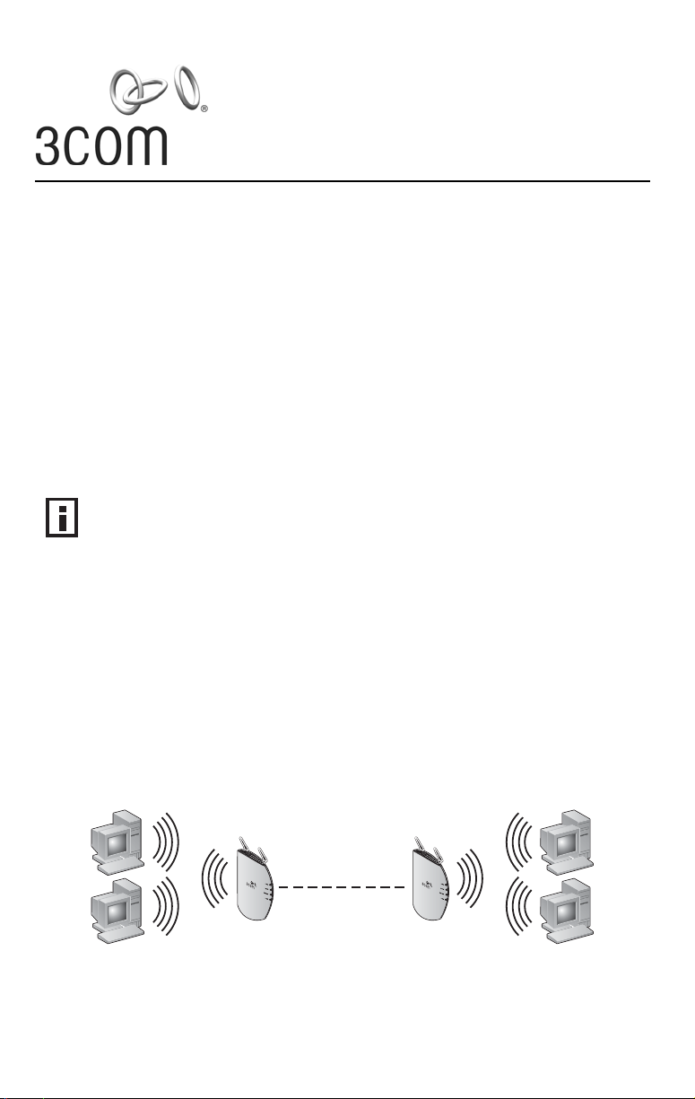
Point-to-Point WDS Link
The following example shows a point-to-point WDS link configured between two access points.
Wireless Desktops Wireless Desktops
WDS Link
1
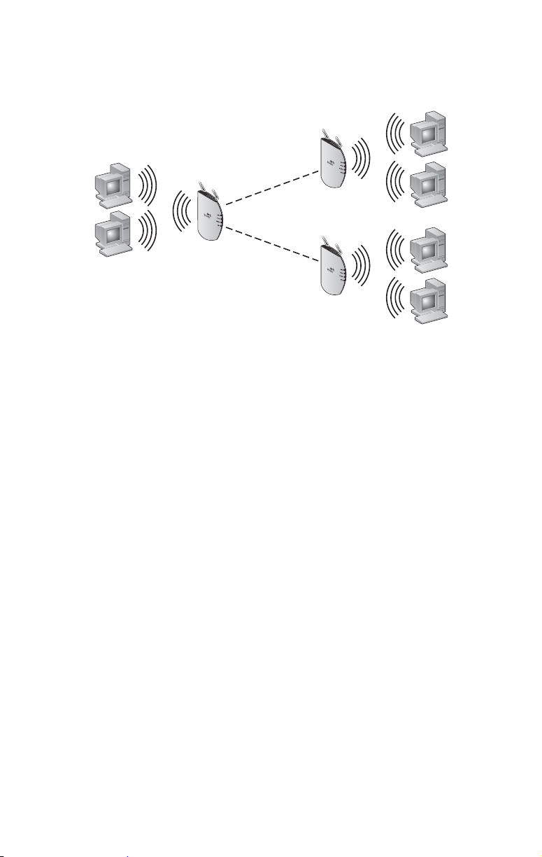
Point-to-Multipoint WDS Link
W
The following example shows point-to-multipoint WDS links configured between multiple access points.
Wireless Desktops
Point-to-Point WDS Link
ireless Desktops
WDS Link
Wireless Desktops
WDS Link
WDS Security and Spanning Tree Support
For added security, the AP 8250 supports AES encryption over the WDS link. Additionally, Spanning Tree
Protocol (STP) support prevents loops from being formed on the network. For more information on these
items, see the Wireless LAN Access Points User Guide.
Configuring WDS Bridging
WDS Bridging can be configured in numerous ways. This section describes two common installation
scenarios and the equipment required to complete the configurations:
Remote building wireless access with the AP8850
Remote building wireless access with the AP8250 and 802.11g Upgrade Kit
Configuration Guidelines
Before configuring the WDS settings, review the following guidelines:
The WDS link can be set up between 3Com access points only.
The pair of access points to be configured with a WDS link must be set to the same
radio channel and SSID, and the link must be set up between 802.11a radios or
802.11g radios (that is, 802.11a to 802.11a or 802.11g to 802.11g).
The access points must be configured with security and standard access point settings
before configuring the WDS link(s).
A Root Bridge can have a maximum of six Child Bridges assigned to it.
A Child Bridge can have a maximum of five Child Bridges assigned to it.
Antenna Guidelines
The 802.11a and 802.11g radios can be used with the following antennas in a bridging application:
802.11a radio: 3CWE591, 3CWE598, 3CWE596
802.11g radio: 3CWE491, 3CWE495, 3CWE498
2
Safety Guidelines
Only a licensed electrician with expert knowledge of outdoor installation and weather proofing
techniques should perform an outdoor installation. Professional network personnel should oversee the
entire installation. The importance of this is paramount, for the sake of compliance with local building
codes, regulatory issues, and for the safety of people and equipment.
CAUTION: Review the safety notices on page 9 before continuing.
!
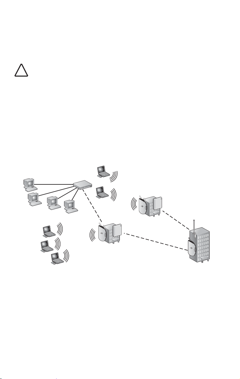
Remote Building Wireless Access with the AP8850
This installation scenario describes one layer of bridging with one Root-Bridge and one Child Bridge. This
scenario is common, for example, in schools or universities where students or professionals in remote
buildings need secure, high-bandwidth wireless access.
In this configuration, an AP 8850 is installed and connected to the wired LAN and at each of the desired
remote locations.
The bridge at the center of the network is configured as the Root Bridge with an
omnidirectional antenna.
The remote bridges are configured as Child Bridges and use directional antennas, which
are aimed at the Root Bridge antenna.
T
M
T
M
Child Bridge 1
Root Bridge
T
M
T
M
T
M
Child Bridge 2
The 802.11g radio at the remote location can be configured with any security configuration desired,
including open security or full WPA security with 802.1X client authentication and AES encryption.
3

Required Products
To use this configuration, you need the following products:
Root-Bridge
Each Remote
Location
Bridge)
(Child
802.11a/g Bridging Access Point (3CRWE885075A)
Ultra Low Loss Cable (3CWE580 or 3CWE581 or 3CWE582)
6/8 Dual-Band Omnidirectional Antenna (3CWE591)
802.11a/g Bridging Access Point (3CRWE885075A)
Ultra Low Loss Cable (3CWE580 or 3CWE581 or 3CWE582)
8/10 dBi Dual-Band Panel Antenna (3CWE598) or one 18/20 dBi Dual-
Band Panel Antenna (3CWE596)
To set up the remote building wireless access:
1 Make sure the AP8850 access points are running the latest
firmware.
To use WDS Bridging, the access points must be running firmware version 3.0.14 or
later. To download the latest firmware, go to the 3Com web site (www.3com.com).
2 Configure the access points with the same Radio and Encryption
settings.
Before physically installing the equipment, configure the access points with the same
Radio and Encryption settings. This configuration is done by connecting to the
Configuration Management System on the access points.
Note: For instructions on connecting to the Configuration Management System, see the
Wireless LAN Access Points User Guide.
a On the access point that is to be configured as the Root-Bridge, open the access point
Configuration Management System and click Advanced Setup.
b Open the Radio Settings page and set the following items:
Transmit antenna—set to the correct antenna port (usually port A, which is the port
that is closest to the LEDs). The transmit antenna must be set to the same port that
the antenna cable is connected to.
Radio Channel—disable the auto channel selection and set the desired radio channel
setting (for example, set the Radio Channel to 152).
SSID—set the desired SSID name (for example, set the SSID name to A Bridge).
c When finished, click Apply.
d Open the Security page for the A radio and set the following items:
Enable Encryption, choose AES as the Cypher Mode, choose WPA Pre-shared Key as
the Key Management, select Alpha Numeric as the Key Type, and enter a password
for the Pre-Shared Key (between 8 and 63 characters; for example, 3ComBridge).
e When finished, click Apply.
f Repeat steps a–e on the Child Bridge A radio.
After the Radio and Encryption settings are set, the access points are ready for the
WDS
link configuration.
4

3 Configure the access points to establish the WDS link.
a On the access point that is to be configured as the Root-Bridge, open the access point
Configuration Management System and click Advanced Setup.
Open the WDS/STP Settings page and set the 802.11a radio to Root-Bridge mode.
Click the Scan for WDS
to as the Child Bridge, copy the MAC address into the Bridge field, and then click
Apply.
Link button. Highlight the access point that you want to link
b On the access point that is to be configured as the Child Bridge, open the access point
Configuration Management System and click Advanced Setup.
Open the WDS/STP Settings page and configure the 802.11a radio to Bridge mode.
Click the Scan for WDS Link button. Highlight the access point you configured as the
Root-Bridge, copy the MAC address into the Parent Bridge field, and then click Apply.
c Reboot the access points.
d On the Child Bridge, open the Configuration Management System, click Advanced
Setup, Status, and then AP Status. Verify the WDS link is active.
After the WDS link is active, the access points are ready for physical installation.
4 Install the Root-Bridge.
The Root-Bridge is installed in the main building that has the physical LAN link.
a Connect the Root-Bridge to the wired LAN.
b Connect the external 3CWE591 antenna to the SMA connector that is closest to the
LEDs on the access point using the 3CWE580 cable.
c Mount the antenna in an area that has a direct “line of sight” from the Root-Bridge to
the Child Bridge.
5 Install the Child Bridge.
The Child Bridge is installed in the remote building where you want to gain wireless
network access.
a Connect the external 3CWE596 antenna to the access point using the 3CWE580 cable.
b Mount the antenna and aim it toward the Root-Bridge antenna.
Note: For best performance, make sure the antennas are mounted at
approximately the same height.
c Plug in the access point and verify the WDS link is active.
To verify the WDS link, access the Configuration Management System and select
Advanced Setup, Status, AP Status.
d Configure the 802.11g radio for local access point service.
The Child Bridge now has a secure wireless connection to the network.
e Connect to the network via the access point to verify the connection.
5

Remote Building Wireless Access with the AP8250 and
802.11g Upgrade Kit
This installation scenario describes one layer of bridging with one Root-Bridge and one Child Bridge. This
scenario is common, for example, in schools or universities where students or professionals in remote
buildings need secure, high-bandwidth 802.11b or 802.11g access to the network.
In this configuration, an AP8250 or AP7250 is placed on the network and an AP8250 with the 802.11g
Upgrade Kit is placed at each of the desired remote locations.
The access point at the center of the network is configured as the Root Bridge with an
omnidirectional antenna.
The remote bridges are configured as Child Bridges and use an 8 dBi directional antenna
.
(3CWE495), which is aimed at the Root-Bridge.
T
M
T
M
Child Bridge 1
Root Bridge
T
M
Child Bridge 2
T
M
T
M
Because the WDS radio and the local access point radio are operating in approximately the same
frequency range, the following guidelines must be followed for successful installation:
The WDS link should be configured on Channel 2 or Channel 10.
The access point radio should be configured on the other Channel (for AP8250 and
AP8750 only).
The directional antenna for the WDS link must be located at least three feet from the
AP8250 and aimed away from the AP8250.
The radio that is using the external antenna must be configured to transmit from the
appropriate antenna connector (this is configured on the Radio
Settings page in the
Configuration Management System).
Required Products
To use this configuration, you need the following products:
Root Bridge
Each Remote
Location
Bridge)
(Child
AP8250 or AP7250 (3CRWE825075A or 3CRWE725075A)
Ultra Low Loss Cable (3CWE580 or 3CWE581 or 3CWE582)
8 dBi Omnidirectional Antenna (3CWE491)
AP8250 (3CRWE825075A)
802.11g Upgrade Kit (3CRWEGMOD75A)
Ultra Low Loss Cable (3CWE580 or 3CWE581 or 3CWE582)
8 dBi Panel Antenna (3CWE498) or 13 dBi Panel Antenna (3CWE495)
6

To set up the remote building wireless access:
1 Make sure the AP8250 access points are running the latest
firmware.
To use WDS Bridging, the access points must be running firmware version 3.1.0 or later.
To download the latest firmware, go to the 3Com web site (www.3com.com).
2 Configure the access points with the same Radio and Encryption
settings.
Before physically installing the equipment, configure the access points with the same
Radio and Encryption settings. This configuration is done by connecting to the
Configuration Management System on the access point.
Note: For instructions on connecting to the Configuration Management System, see the
Wireless LAN Access Points User Guide.
a On the access point that is to be configured as the Root-Bridge, open the access point
Configuration Management System and click Advanced Setup.
b Open the Radio Settings page and set the following items:
Transmit antenna—set to the correct antenna port (usually port A, which is the port
that is closest to the LEDs). The transmit antenna must be set to the same port that
the antenna cable is connected to.
Radio Channel—disable the auto channel section, and set the desired radio channel
settings (for example, set the Radio Channel to 6).
SSID—set the desired SSID name (for example, set the SSID name to G Bridge).
c When finished, click Apply.
d Open the Security page for the G radio and set the following items:
Enable Encryption, choose AES as the Cypher Mode, choose WPA Pre-shared Key as
the Key Management, select Alpha Numeric as the Key Type, and enter a password
for the Pre-shared key (between 8 and 63 characters; for example, 3ComBridge).
Repeat steps on the Child Bridge G Radio.
e When finished, click Apply.
f Repeat steps a–e on the access point that is to be configured as the Child Bridge.
3 Configure the access points to establish the WDS link.
a On the access point that is to be configured as the Root-Bridge, open the access point
Configuration Management System and click Advanced Setup.
Open the WDS/STP Settings page and set the 802.11g radio to Root-Bridge mode.
Click the Scan for WDS
to as the Child Bridge, copy the MAC address into the Child Bridge field, and then
click Apply.
b On the access point that is to be configured as the Child Bridge, open the access point
Configuration Management System and click Advanced Setup.
Open the WDS/STP Settings page and configure the 802.11a radio to Bridge mode.
Click the Scan for WDS Link button. Highlight the access point you configured as the
Root-Bridge, copy the MAC address into the Parent Bridge field, and then click Apply.
c Reboot the access points.
d On the Child Bridge, open the Configuration Management System, click Advanced
Setup, Status, and then AP Status. Verify the WDS link is active.
After the WDS link is active, the access points are ready for physical installation.
Link button. Highlight the access point that you want to link
7

4 Install the Root-Bridge.
The Root-Bridge is installed in the main building that has the physical LAN link.
a Connect the Root-Bridge to the wired LAN.
b Connect the external 3CWE491 antenna to the SMA connector that is closest to the
LEDs on the access point using the 3CWE580 cable.
c Mount the antenna in an area that has a direct “line of sight” from the Root-Bridge to
the Child Bridge.
5 Install the Child Bridge.
The Child Bridge is installed in the remote building where you want to gain wireless
network access.
a Connect the external 3CWE596 antenna to the access point using the 3CWE580 cable.
b Mount the antenna and aim it toward the Root-Bridge antenna.
Note: For best performance, make sure the antennas are mounted at
approximately the same height.
c Plug in the access point and verify the WDS link is active.
To verify the WDS link, access the Configuration Management System and select
Advanced Setup, Status, AP Status.
d Configure the 802.11g radio for local access point service.
The Child Bridge now has a secure wireless connection to the network.
e Connect to the network via the access point to verify the connection.
8

Safety Notices
This equipment must be installed in compliance with local and national building codes, regulatory
restrictions, and FCC rules. For the safety of people and equipment, only professional network personnel
should install the equipment, cables, and antennas.
WARNING: Do not install the antennas near overhead power lines, electric light or power
circuits, or where it can come into contact with such circuits. Provide ten feet or more
clearance between the antenna and such power lines or circuits. Do not install the bridge
flush with the rooftop or wall. When installing the bridge, do not come into contact with
such circuits, which can cause serious injury or death. Follow local and national codes for
proper installation and grounding of antennas.
CAUTION: To comply with FCC radio frequency (RF) exposure limits, antennas should be
located at least two meters (six feet) or more from the bodies of all persons.
!
CAUTION: Do not install the bridge or connect and disconnect cables during periods of
lightning activity.
!
CAUTION: To avoid possible injury or damage to equipment, you must use either the
provided power supply or IEEE 802.3af compliant power supply equipment that is safety
!
certified according to UL, CSA, IEC, or other applicable national or international safety
requirements for the country of use. All references to power supply in this document refer
to equipment meeting these requirements.
CAUTION: It is the responsibility of the installer to ensure that the power over Ethernet (POE)
power supply is properly connected. Connection to any other device, such as a standard
!
Ethernet card or another POE supply, may result in permanent damage to equipment, electric
shock, or fire. Refer to the installation instructions for proper installation.
CAUTION: The 3Com power supply (part number 61-0107-000) input relies on a 16A rated
building fuse or circuit protector for short circuit protection of the line to neutral conductors.
!
CAUTION: If the antenna is installed outside, you need to use a lightning arrestor. 3Com
recommends the Huber Suhner lightning protector, item number 22652538. For more
!
information on this product, go to http://products.hubersuhner.com.
A lightning arrestor will not prevent damage from direct lightning strikes. It is extremely
important to ensure that the bridge is installed at least 1 meter (3 feet) below the top of the
grounded pole or mast.
CAUTION: Minimize damage from direct lightning strikes by mounting the antenna at least
1 Meter (3 feet) below the top of the mast.
!
9

Copyright © 2005 3Com Corporation. All rights reserved. 3Com, and the 3Com Logo are registered
trademarks of 3Com Corporation. All other company and product names may be trademarks of the
respective companies with which they are associated.
Part No. DIA72507-5AAA01
Published March 2005
 Loading...