

Page 1

OfficeConnect® Gateway
ADSL Data and Voice (3CR100AV97)
Quick Start Guide
Page 2

3Com Corporation
5400 Bayfront Plaza
Santa Clara, California 95052-8145
Copyright © 2001 3Com Corporation. All rights reserved. No part of this documentation may be reproduced in any form or by any
means or used to make any derivative work (such as translation, transformation, or adaptation) without written permission from 3Com
Corporation.
3Com Corporation reserves the right to revise this documentation and to make changes in content from time to time without obligation
on the part of 3Com Corporation to provide notification of such revision or change.
3Com Corporation provides this documentation without warranty of any kind, either implied or expressed, including, but not limited
to, the implied warranties of merchantability and fitness for a particular purpose. 3Com may make improvements or changes in the
product(s) and/or the program(s) described in this documentation at any time.
UNITED STATES GOVERNMENT LEGENDS:
If you are a United States government agency, then this documentation and the software described herein are provided to you subject
to the following:
United States Government Legend: All technical data and computer software is commercial in nature and developed solely at private
expense. Software is delivered as Commercial Computer Software as defined in DFARS 252.227-7014 (June 1995) or as a commercial
item as defined in FAR 2.101(a) and as such is provided with only such rights as are provided in 3Com’s standard commercial license
for the Software. Technical data is provided with limited rights only as provided in DFAR 252.227-7015 (Nov 1995) or FAR 52.227-14
(June 1987), whichever is applicable. You agree not to remove or deface any portion of any legend provided on any licensed program
or documentation contained in, or delivered to you in conjunction with this Quick Start Guide.
Unless otherwise indicated, 3Com registered trademarks are registered in the United States and may or may not be registered in other
countries.
3Com and OfficeConnect are registered trademarks of 3Com Corporation. The 3Com logo is a trademark of 3Com Corporation. All other
company and product names may be trademarks of their respective companies.
FCC Class A Statement
UNITED STATES
NOTE: This equipment has been tested and found to comply with the limits for a Class A digital device, pursuant to Part 15 of the FCC
Rules. These limits are designed to provide reasonable protection against harmful interference when the equipment is operated in a
commercial environment. This equipment generates, uses and can radiate radio frequency energy and, if not installed and used in
accordance with the instruction manual, may cause harmful interference to radio communications. However, there is no guarantee that
interference will not occur in a particular installation. Operation of this equipment in a residential area is likely to cause harmful interference in which case the user will be required to correct the interference at his own expense.
This device complies with part 15 of the FCC Rules. Operation is subject to the following two conditions:
(1) This device may not cause harmful interference, and
(2) this device must accept any interference received, including interference that may cause undesired operation.
CANADA
This Class A digital apparatus complies with Industry Canada Standard ICES-003.
Cet appareil numérique de la classe A est conforme à la norme NMB-003 d’Industrie Canada.
EUROPE
This is a Class A product. In a domestic environment this product may cause radio interference in which case the user may be required
to take adequate measures.
This product contains 168-bit Encryption and may require US and/or Local Government
authorization prior to export or import to another country.
Page 3

1
Congratulations on choosing the 3Com®OfficeConnect®Gateway,
your ADSL (Asymmetric Digital Subscriber Line) broadband
access solution. This guide describes how to set up the
OfficeConnect Gateway Data and Voice (3CR100AV97) base unit.
The OfficeConnect Gateway allows one or more networked
computers to connect to the Internet or a remote LAN (Local
Area Network). Once connected, local users (a local branch office)
can communicate with remote computers (the main office) as if
they were connected locally.
The four POTS (Plain Old Telephone System) voice ports enable
simultaneous delivery of up to four voice calls and continuous
high-speed Internet or remote LAN access over a single DSL
interface.
Setting up the OfficeConnect Gateway Data and Voice unit is a
three-step process:
1) Unpacking and positioning
2) Connecting the cables
3) Configuring the OfficeConnect Gateway
Introduction
Before You
Begin
This guide describes how to install and configure the
OfficeConnect Gateway Data and Voice base unit for broadband
internet access using the unit’s default settings. For most users,
you will not need to modify the default settings to support your
broadband access requirements.
To set up your OfficeConnect Gateway Data and Voice base unit
for shared access to the internet, you must have the following:
• An Internet Service Provider (ISP) account.
• ADSL Service already installed at your location, with an avail-
able ADSL wall jack, configured for data and voice services.
• A computer (PC) with Ethernet connectivity and TCP/IP soft-
ware. (Note: TCP/IP is automatically included with Windows
2000, ME, 98, 95, and NT.)
• A Web Browser, such as Microsoft Internet Explorer (4.0 or
later) or Netscape Navigator (4.0 or later), installed on your
computer.
Page 4

Figure 1
2
Unpack the contents and ensure that it includes the following
items:
• AC/DC, 18 watt Power Adapter and Power Cord
• LAN Cable, RJ-45 (CAT-5), Blue
• ADSL Cable RJ-11/RJ-11, Black
• One RJ-11, 7-ft telephone cable, Silver
• Rubber feet (4)
• Stacking clip
Positioning
the
Gateway
Package
Contents
When positioning your OfficeConnect Gateway, make sure of the
following:
• Unit is out of direct sunlight and away from sources of heat.
• Cabling is away from power lines, fluorescent lighting fixtures,
and sources of electrical noise such as radios, transmitters, and
amplifiers.
• Water or moisture cannot enter the case of the unit.
• Air flow around the unit and through the vents in the side and
back of the case is not restricted. A minimum of 1 in. (2.54 cm)
clearance is recommended.
Using Rubber Feet and Stacking Clip
For desktop use, the four self-adhesive rubber feet
help to stabilize your OfficeConnect Gateway and prevent sliding. Attach the feet to the marked areas at
each corner of the underside of your OfficeConnect
Gateway.
In addition, the stacking clip provided may be used
for stacking any other OfficeConnect units, such as the
OfficeConnect Gateway Voice Expansion Unit or
OfficeConnect Ethernet hubs and switches, neatly and
securely together. You can stack up to a maximum of
four units. To stack your units, secure the clip as
shown in Figure 1.
Page 5
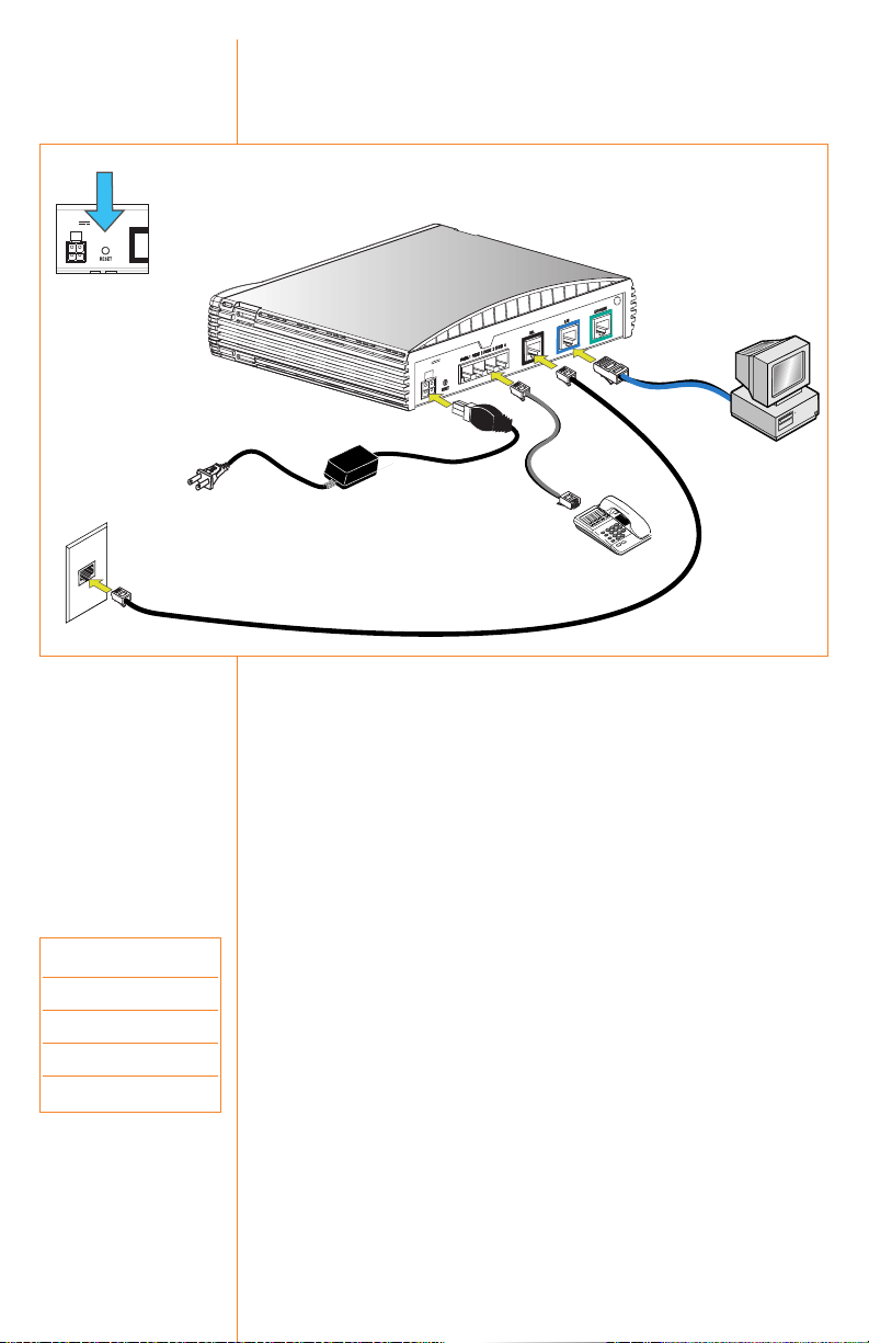
3
The ports and cables of the OfficeConnect Gateway products are
color-coded to help you connect the cables properly.
The following illustration shows the connector cabling:
To connect the OfficeConnect Gateway’s cables:
1. Connect the DSL cable.
Connect the DSL cable (black) to the ADSL wall jack and the
other end to the DSL port (black) of your OfficeConnect Gateway.
2. Connect the LAN cable.
Connect one end of the LAN cable (blue) to the Ethernet port of
your computer and the other end to the LAN port (blue) on the
rear panel of the OfficeConnect Gateway.
3. Connect the Telephone Cable(s).
You can connect up to four POTS-based devices (telephones, fax
machines, or modems) to the Phone ports of the OfficeConnect
Gateway, using telephone cables (silver) such as the one provided. Your Service Provider assigns phone numbers to each
port, and can tell you which phone ports on your unit correspond to the phone numbers. You can use the table on the left to
record the unique phone number for each phone port.
4. Connect the power adapter.
Connect the cable from the power adapter to the Power inlet on
the rear panel of the unit. Connect the power cord to the power
adapter. Connect the other end of the power cord into a surgeprotected electrical outlet.
Connect
Cables
Phone Phone
Port Number
1
2
3
4
Figure 2
Note: If you will be using
the 3Com OfficeConnect
Gateway Voice Expansion
Unit (3C100XF) with your
base unit, please refer to
the Quick Start Guide supplied with the Voice
Expansion Unit for configuration and installation
information.
Reset Button
12V DC
1.5 A MAX
2
LAN Connection
C
D
X
V
A
12
M
1.5 A
4
Power
DSL Connection
1
Phone Connections
3
Page 6

DHCP: (Dynamic Host
Configuration Protocol)
:
Dynamic IP addressing is the
type of addressing scheme
most often used by Internet
Service Providers (ISPs), and
is also the type that is prevalent in many existing
corporate networks.
The OfficeConnect Gateway,
which can act as a DHCP
server, is optimized for use
with dynamic, rather than
static, IP addressing.
For most users, it is most
likely that your computer or
computers are already set up
for dynamic IP addressing. By
default, the OfficeConnect
Gateway assigns IP addresses
dynamically to each attached
computer.
Each computer must be properly set up with TCP/IP and optimized for use with dynamic IP addressing.
Checking for Dynamic or Static IP Addressing
• From the Start Menu, select Settings, and then Control Panel.
Windows 95, 98 or NT:
Double-click the Network icon. From the Configuration tab of
the Network window, select TCP/IP for the Ethernet Network
Interface Card (NIC) that will be associated with your
OfficeConnect Gateway. For Windows NT: Click the Protocols tab
on the Network window, and then select TCP/IP. Click
Properties. Click the IP Address tab on the TCP/IP Properties
window.
Windows 2000:
Double-click the Network and Dial-up Connections icon, then
double-click the Local Area Connection icon. Click Properties
on the Local Area Connection Status window and then select
Internet Protocol (TCP/IP) from the list of components shown
on the General tab of the Local Area Connection Properties
window. Click the General tab on the Internet Protocol (TCP/IP)
Properties window.
• If Obtain an IP address automatically (Windows 95, 98, 2000) or
Obtain an IP address from a DHCP server (Windows NT) is
selected, your computer has a dynamic IP address.
• If Specify an IP address is selected, your computer has a static
IP address.
• Click Cancel to exit the window, and then click Cancel again on
the remaining windows until you get back to the Control Panel.
Where To Go from here…
If you are set up for dynamic IP addressing, proceed to the next
section, Configure the Gateway. If you are set up for static IP
addressing, record your settings. You will need them for your
final setup. Then set up dynamic addressing so you can continue
with the configuration of the OfficeConnect Gateway.
Once the unit is connected, the Power LED illuminates (green) on
the front panel of the OfficeConnect Gateway Data and Voice
unit. Wait for the Alert LED on the front panel to stop flashing
(amber) and transition to off, within 1-2 minutes.
When the Power LED is green and the Alert LED is off, it
indicates that the OfficeConnect Gateway Data and Voice unit has
successfully powered up, performed a Power On Self-Test (POST)
and is now operational.
4
Operational
Status
Optimizing
Your
Computer
Static IP Settings:
IP: ___ . ___ . ___ . ___
Mask: ___ . ___ . ___ . ___
GW: ___ . ___ . ___ . ___
DNS1: ___ . ___ . ___ . ___
DNS2: ___ . ___ . ___ . ___
Page 7

5
Configure
the Gateway
The following procedure describes how to initially configure the
Wide Area Network (WAN) interface settings for your
OfficeConnect Gateway or re-configure them after resetting the
unit to its factory default settings.
Using a web browser on your PC, launch the OfficeConnect
Gateway home page by entering the OfficeConnect Gateway’s
default IP address, 192.168.1.1.
If after the initial connection the
OfficeConnect Gateway home
page (Fig 3) is displayed, then
the WAN interface has already
been configured for you.
Congratulations, your
OfficeConnect Gateway is
successfully configured and is
ready for use.
If the WAN Interface Inactive message is displayed (Fig 4), your
first step is to create a password protected admin account and
configure the WAN interface.
Click Continue to proceed.
The system will display the
Username and Password Required
window (Fig 5) and prompts for
Username and Password. (Note:
The User Name and Password
entries are case-sensitive.)
The default value for the User Name is admin. There is no
default Password value. Enter admin in the User Name field and
leave the Password field blank (no entry). Click OK.
The system will display the Unprotected User window (Fig 6). You
need to assign a Password for your User Name (admin). This
window is displayed when the OfficeConnect Gateway Web
Configurator is accessed using
the system’s default password;
such as during the initial configuration of the unit or after the
factory default settings have
been restored.
Click Apply and the WAN Interface Configuration screen will
appear. Continue on to the WAN Configuration section on page 6.
Figure 4
Figure 5
Figure 6
Figure 3
Page 8

RFC1483
Dynamic
Configuration
WAN
Configuration
Related
Documents
The only information required for an RFC 1483 configuration in a
dynamic environment are the VPI/VCI numbers from your ISP.
The DHCP Client over WAN setting is enabled, and unless
instructed otherwise, the IP Routing Protocol should be set to
RIPv2.
Assign a meaningful name to your configuration in the PVC Name
(Private Virtual Circuit)
field, and record your settings here:
PVC Name: ________________ VPI: _______ VCI: _______
Click the Apply button to apply your changes.
After you successfully created your administrative account
and assigned a password, you can now start the WAN
configuration.
The WAN Configuration page is displayed (Fig 7).
Important: Before you begin, ensure that you have obtained all
required WAN parameter information from your Service Provider
to properly configure the connection.
To configure a WAN protocol, select it from the WAN Protocol
field’s drop-down menu. The following WAN protocols are supported: RFC 1483 (ATM Adaptation Layer 5 Protocol), RFC
1483-MER (MAC Encapsulated
Routing), PPPoE (Point-to-Point
Protocol over Ethernet), PPPoA
(LLC-SNAP) (Point-to-Point
Protocol over ATM with Logical
Link Control), and PPPoA (VCMux) (Point-to-Point Protocol
over ATM with Virtual Circuit).
When you select a WAN protocol, the WAN Configuration page
interactively changes to display
the fields associated with the
selected protocol.
For a description of each field on the WAN Configuration page,
click the Help button.
After the WAN configuration is complete and you are connected,
go to the Documentation link in the online help section, to get
more detailed information and step-by-step instructions in the
OfficeConnect Gateway User’s Guide. Alternately you can type
www.3com.com/ocg/docs directly in your browser’s address bar.
6
Figure 7
Page 9

RFC1483
Static
Configuration
PPPoE or
PPPoA
Configuration
Voice
Configuration
Save Your
Configuration
In an RFC 1483 or an RFC 1483-MER configuration with static IP
addressing, the DHCP Client over WAN setting is disabled. You
will also see fields for local and remote WAN IP addresses, and
for the WAN IP Mask.
Assign a meaningful name to your configuration in the PVC
Name field, and record your settings here:
PVC Name: ________________ VPI: _______ VCI: _______
Local WAN IP Address: _____ . _____ . _____ . _____
Remote WAN IP Address: _____ . _____ . _____ . _____
WAN IP Mask: _____ . _____ . _____ . _____
Click the Apply button to apply your changes.
The PPPoE and PPPoA configurations require a PPP login
account with your Service Provider, in addition to VPI/VCI
numbers and IP addresses. Select the appropriate protocol from
the WAN Protocol drop-down menu.
Assign a meaningful name to your configuration in the PVC
Name field, and record your settings here:
User Name: _______________ Password: _______________
PVC Name: ________________ VPI: _______ VCI: _______
If the Service Provider uses dynamic addressing, set the Address
Selection field to Negotiate. For static addressing, set the field to
Specified and complete the fields below:
Local WAN IP Address: _____ . _____ . _____ . _____
Remote WAN IP Address: _____ . _____ . _____ . _____
WAN IP Mask: _____ . _____ . _____ . _____
Click the Apply button to apply your changes.
The Voice Configuration page contains the fields required to configure the phone lines for your OfficeConnect Gateway Data and
Voice base unit. The same settings also apply to the phone ports
of the optional OfficeConnect Gateway Voice Expansion unit.
Select the appropriate Gateway from the drop-down menu, fill in
the VPI and VCI numbers, and select the Companding value as
specified by your Service Provider. Record your settings here:
Gateway: _____________ VPI: _______ VCI: _______
Click the Apply button to apply your changes.
Important: Remember to save your completed configuration using
the SaveAll button.
7
Page 10
Rebooting the OfficeConnect Gateway Data and Voice Base Unit:
To reboot an OfficeConnect Gateway Data and Voice unit that is
powered up, press and hold the Reset button for at least two
seconds.
Reset Button
The Reset button is located on the rear panel of the OfficeConnect
Gateway Data and Voice Base Unit, as previously shown in the
installation diagram (Fig 2) on page 3.
Restoring Factory Default Settings:
To restore the factory default settings of the OfficeConnect
Gateway, press and hold the Reset button for five (5) seconds
while power-cycling the unit. This will restore the factory
default settings to all OfficeConnect Gateway parameters,
including the Administrator password.
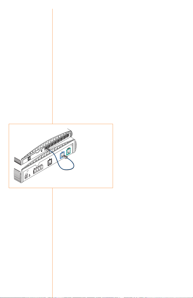
Connecting an additional hub:
After you have finished the configuration of your OfficeConnect
Gateway, you can connect an additional Ethernet hub or hubs to
add up to 253 users, which is the maximum supported by the
OfficeConnect Gateway.
Note: If you previously used static addressing, use Chapter 2 of
the User’s Guide (available online at www.3com.com/ocg/docs) and
the settings you recorded earlier to set up your workstations and
the OfficeConnect Gateway for static IP addressing.
An example of an eight-user connection is shown below (Fig 8),
using a 3Com OfficeConnect Ethernet Hub 8.
1. Verify network configuration.
Check with your network administrator that the built-in DHCP
server will not cause conflicts on the network. In most instances,
however, the OfficeConnect Gateway will automatically detect
the presence of another DHCP server on the network and disable
its own built-in DHCP server.
2. Connect the LAN cable.
Connect one end of the LAN cable
(blue) to a port of the ethernet
hub and the other end to the LAN
port (blue) on the rear panel of the
OfficeConnect Gateway.
3. Uplink port configuration
The OfficeConnect Gateway will
automatically detect uplink ports
and configure itself accordingly.
No further action is required.
8
Connecting
multiple
users
Rebooting
the Unit
Figure 8
C
D
V
X
8
A
-1
0
M
1
A
0• 8
X
A
M
A
1.5
OfficeConnect
Ethernet Hub 8
1
2
3
5 4
6
7
8
IX
D
I/M
D
M
OfficeConnect Gateway
ADSL Data and Voice
Ethernet cable
Page 11

9
The LED Indicators on the front panels of the OfficeConnect
Gateway Data and Voice unit provide the following information:
Front Panel
Indicators
Alert
Off Off indicates the unit has passed the Power On Self-Test and is working properly.
Amber (blinking) Lit during Power On Self-Test or software upgrade.
Red Indicates a diagnostic failure in the unit. Refer to the Troubleshooting section in the
OfficeConnect Gateway User’s Guide.
Power
Off Power not being supplied to the unit.
Green Remains lit as long as power is supplied to the unit.
DSL Status
Link Off DSL connection not established.
Yellow (blinking) Establishment of Layer 1 WAN Link in progress.
Green, then Yellow (blinking) Establishment of Layer 2 WAN Link in progress.
Note: May not see yellow with a fast establishment of the Layer 2 WAN.
Green DSL connection established.
Data Off No user traffic on the DSL link.
Green (blinking) User traffic on the DSL link.
Green Heavy user traffic on the DSL link.
LAN Status
10 Off Disabled or no 10 Mbit traffic.
Green 10 Mbit Link Integrity.
100 Off Disabled or no 100 Mbit traffic.
Green 100 Mbit Link Integrity.
Data Off No LAN Port traffic.
Green (blinking) LAN Port traffic.
Green Heavy LAN Port traffic.
Phone Status
1- 4 Off Onhook. The phone port is not being used.
Green Offhook. The phone port is being used.
Page 12

Information contained in this document is correct at time of
publication. The following services are available 24 hours a day, 7
days a week. For the most up–to–date information, 3Com recommends that you access the 3Com Corporation World Wide Web
site.
World Wide Web Site http://www.3com.com
This service provides access to online support information such
as technical documentation and software library, as well as support options ranging from technical education to maintenance
and professional services.
Support from Your Network Supplier
If additional assistance is required, contact your network supplier. Many suppliers are authorized 3Com service partners who
are qualified to provide a variety of services, including network
planning, installation, hardware maintenance, application training, and support services.
When you contact your network supplier for assistance, have the
following information ready:
• Product model name, part number, and serial number
• A list of system hardware and software, including revision levels
• Diagnostic error messages
• Details about recent configuration changes, if applicable
If you are unable to contact your network supplier, see the
following section on how to contact 3Com.
Support from 3Com
If you are unable to obtain assistance from the 3Com online
technical resources or from your network supplier, 3Com offers
technical telephone support services. To find out more about
your support options, please call the 3Com technical telephone
support phone number at the location nearest you. Please refer to
the table on page 11.
When you contact 3Com for assistance, have the following
information ready:
• Product model name, part number, and serial number
• A list of system hardware and software, including revision levels
• Diagnostic error messages
• Details about recent configuration changes, if applicable
10
Technical
Support
Page 13

Returning Products for Repair
Before you send a product directly to 3Com for repair, you must
first obtain a Return Materials Authorization (RMA) number.
Products sent to 3Com without RMA numbers will be returned to
the sender unopened, at the sender’s expense.
To obtain an RMA number, please call the local number for your
region, listed below.
11
Asia Pacific Rim http://www.3com.com/apr
Australia 1 800 678 515
Hong Kong 800 933 486
India 000 800 650 1111
+61 2 9937 5085
Indonesia 001 800 61 009
Japan 03 5783 1270
Malaysia 1 800 801 777
New Zealand 0 800 446 398
Pakistan +61 2 9937 5085
Philippines 1 235 61 266 2602
P. R. of China 00 800 0638 3266
10 800 61 00137
021 6350 1590
Singapore 800 6161 463
South Korea 00798 611 2230
02 3455 6455
Taiwan, R.O.C 0080 611 261
Thailand 001 800 611 2000
Middle East, Africa http://www.3com.com/meaf
All locations 971 4 807 4555
North America http://www.3com.com
North America 1 800 net 3Com
(1 800 638 3266)
Europe http://www.3com.com/europe
Austria 07110 900116
Belgium 32 (0) 70 233 545 (Flemish)
32 (0) 70 233 546 (French)
Denmark 45 (0) 35 44 5531
Finland 358 (0) 98170015
France 33 (0) 803 070693
Germany 49 (0) 180 567 1548
Hungary 49 (0) 180 567 1548
Israel 971 4 807 4555
Italy 147 809 903
Luxembourg 352 342 080 8318
Netherlands 0900 20 25 857
Norway 47 (0) 23 50 0097
Poland 49 (0) 180 567 1548
Portugal 351 (21) 4154034
Spain 902 117 964
Sweden 46 (0) 851 992 0305
Switzerland 0 848 840200
United Kingdom 0 870 8444546
Latin America http://www.3com.com/ami
Argentina 0 810 444 3266
Brazil 0 900 133 266
Colombia 9 800 11 3266
Mexico City 0 1 800 849 2273
Other Latin America AT&T Direct + 800 998 2112
Page 14

12
3Com Corporation Limited Warranty
The duration of the warranty for the OfficeConnect Gateway is Lifetime.
Hardware
3Com warrants the OfficeConnect Gateway to be free from defects in workmanship and materials,
under normal use and service, for lifetime from the date of purchase from 3Com or its authorized
reseller.
If a product does not operate as warranted above during the applicable warranty period, 3Com shall, at
its option and expense, repair the defective product or part, deliver to Customer an equivalent product
or part to replace the defective item, or refund to Customer the purchase price paid for the defective
product. All products that are replaced will become the property of 3Com. Replacement products may
be new or reconditioned. Any replaced or repaired product or part has a ninety (90) day warranty or
the remainder of the initial warranty period, whichever is longer.
Software
3Com warrants that the software programs licensed from it will perform in substantial conformance to
the program specifications therefor for a period of ninety (90) days from the date of purchase from
3Com or its authorized reseller. 3Com warrants the media containing software against failure during
the warranty period. No updates are provided. 3Com’s sole obligation with respect to this express war-
ranty shall be (at 3Com’s discretion) to refund the purchase price paid by Customer for any defective
software products, or to replace any defective media with software which substantially conforms to
applicable 3Com published specifications. Customer assumes responsibility for the selection of the
appropriate applications program and associated reference materials. 3Com makes no warranty or representation that its software products will meet Customer’s requirements or work in combination with
any hardware or applications software products provided by third parties, that the operation of the
software products will be uninterrupted or error free, or that all defects in the software products will
be corrected. For any third party products listed in the 3Com software product documentation or specifications as being compatible, 3Com will make reasonable efforts to provide compatibility, except
where the non-compatibility is caused by a “bug” or defect in the third party’s product.
Obtaining Warranty Service
Customer must contact 3Com’s Corporate Service Center or an Authorized 3Com Service Center within
the applicable warranty period to obtain warranty service authorization. Dated proof of purchase may
be required. Products returned to 3Com’s Corporate Service Center must be pre-authorized by 3Com
with a Return Material Authorization (RMA) number marked on the outside of the package, and sent
prepaid and packaged appropriately for safe shipment, and it is recommended that they be insured.
The repaired or replaced item will be shipped to Customer, at 3Com’s expense, not later than thirty
(30) days after receipt of the defective product by 3Com.
Dead- or Defective-on-Arrival. In the event a product completely fails to function or exhibits a
defect in materials or workmanship within the first forty-eight (48) hours of installation but no later
than thirty (30) days after the date of purchase, and this is verified by 3Com, it will be considered
dead- or defective-on-arrival (DOA) and a replacement shall be provided by advance replacement. The
replacement product will normally be shipped not later than three (3) business days after 3Com’s
verification of the DOA product, but may be delayed due to export or import procedures. When an
advance replacement is provided and Customer fails to return the defective product to 3Com within
fifteen (15) days after shipment of the replacement, 3Com will charge Customer for the replacement
product, at list price.
3Com shall not be responsible for any software, firmware, information, or memory data of Customer
contained in, stored on, or integrated with any products returned to 3Com for repair, whether under
warranty or not.
Telephone Support, with coverage for basic troubleshooting only, will be provided for one year, on a
commercially reasonable efforts basis. Telephone support from 3Com is available from 3Com, only if
Customer purchased this product directly from 3Com, or if Customer’s reseller is unable to provide
telephone support. Please refer to the Technical Support section in this Quick Start Guide for telephone
numbers.
Page 15

13
Warranties Exclusive
IF A 3COM PRODUCT DOES NOT OPERATE AS WARRANTED ABOVE, CUSTOMER’S SOLE REMEDY
FOR BREACH OF THAT WARRANTY SHALL BE REPAIR, REPLACEMENT, OR REFUND OF THE PURCHASE PRICE PAID, AT 3COM’S OPTION. TO THE FULL EXTENT ALLOWED BY LAW, THE FOREGOING WARRANTIES AND REMEDIES ARE EXCLUSIVE AND ARE IN LIEU OF ALL OTHER WARRANTIES, TERMS, OR CONDITIONS, EXPRESS OR IMPLIED, EITHER IN FACT OR BY OPERATION
OF LAW, STATUTORY OR OTHERWISE, INCLUDING WARRANTIES, TERMS, OR CONDITIONS OF
MERCHANTABILITY, FITNESS FOR A PARTICULAR PURPOSE, AND SATISFACTORY QUALITY.
3COM NEITHER ASSUMES NOR AUTHORIZES ANY OTHER PERSON TO ASSUME FOR IT ANY
OTHER LIABILITY IN CONNECTION WITH THE SALE, INSTALLATION, MAINTENANCE OR USE OF
ITS PRODUCTS.
3COM SHALL NOT BE LIABLE UNDER THIS WARRANTY IF ITS TESTING AND EXAMINATION DISCLOSE THAT THE ALLEGED DEFECT IN THE PRODUCT DOES NOT EXIST OR WAS CAUSED BY
CUSTOMER’S OR ANY THIRD PERSON’S MISUSE, NEGLECT, IMPROPER INSTALLATION OR TEST-
ING, UNAUTHORIZED ATTEMPTS TO REPAIR OR MODIFY, OR ANY OTHER CAUSE BEYOND THE
RANGE OF THE INTENDED USE, OR BY ACCIDENT, FIRE, LIGHTNING, OR OTHER HAZARD.
Limitation of Liability
TO THE FULL EXTENT ALLOWED BY LAW, 3COM ALSO EXCLUDES FOR ITSELF AND ITS SUPPLIERS ANY LIABILITY, WHETHER BASED IN CONTRACT OR TORT (INCLUDING NEGLIGENCE), FOR
INCIDENTAL, CONSEQUENTIAL, INDIRECT, SPECIAL, OR PUNITIVE DAMAGES OF ANY KIND, OR
FOR LOSS OF REVENUE OR PROFITS, LOSS OF BUSINESS, LOSS OF INFORMATION OR DATA, OR
OTHER FINANCIAL LOSS ARISING OUT OF OR IN CONNECTION WITH THE SALE, INSTALLATION, MAINTENANCE, USE, PERFORMANCE, FAILURE, OR INTERRUPTION OF ITS PRODUCTS,
EVEN IF 3COM OR ITS AUTHORIZED RESELLER HAS BEEN ADVISED OF THE POSSIBILITY OF
SUCH DAMAGES, AND LIMITS ITS LIABILITY TO REPAIR, REPLACEMENT, OR REFUND OF THE
PURCHASE PRICE PAID, AT 3COM’S OPTION. THIS DISCLAIMER OF LIABILITY FOR DAMAGES
WILL NOT BE AFFECTED IF ANY REMEDY PROVIDED HEREIN SHALL FAIL OF ITS ESSENTIAL
PURPOSE.
Disclaimer
Some countries, states, or provinces do not allow the exclusion or limitation of implied warranties or
the limitation of incidental or consequential damages for certain products supplied to consumers or the
limitation of liability for personal injury, so the above limitations and exclusions may be limited in
their application to you. When the implied warranties are not allowed to be excluded in their entirety,
they will be limited to the duration of the applicable written warranty. This warranty gives you specific legal rights which may vary depending on local law.
Governing Law
This Limited Warranty shall be governed by the laws of the State of California, U.S.A. excluding its
conflicts of laws principles and excluding the United Nations Convention on Contracts for the
International Sale of Goods.
3Com Corporation, 5400 Bayfront Plaza, Santa Clara, CA 95052-8145 (408) 764-5000
Page 16

3Com Corporation,
Corporate Headquarters,
5400 Bayfront Plaza, Santa Clara,
CA 95052-8145, USA.
To learn more about 3Com solutions,
visit www.3com.com. 3Com Corporation
is publicly traded on Nasdaq under the
symbol COMS.
All specifications are subject to change
without notice.
Printed in the U.S.A.
Part No. 10045511 Rev. AB 07/01
 Loading...