

Page 1
NJ95
Network Jack
User Guide
3CNJ95
Page 2

Page 3

User Guide
NJ95 Network Jack
3CNJ95
4-port 10/100 Mbps Unmanaged
Ethernet Switch
http://www.3com.com/
http://www.3com.com/productreg
09-2264-000
Published October 2002
Page 4

3Com Corporation ■ 5400 Bayfront Plaza
Santa Clara, California ■ 95052-8145 ■ U.S.A.
Copyright © 2001 3Com Corporation. All rights reserved. No part of this
documentation may be reproduced in any form or by any means or used to
make any derivative work (such as translation, transformation, or adaptation)
without written permission from 3Com Corporation.
3Com Corporation reserves the right to revise this documentation and to
make changes in content from time to time without obligation on the part of
3Com Corporation to provide notification of such revision or change. 3Com
Corporation provides this documentation without warranty, term, or condition
of any kind, either implied or expressed, including, but not limited to, the
implied warranties, terms or conditions of merchantability, satisfactory quality,
and fitness for a particular purpose. 3Com may make improvements or
changes in the product(s) and/or the program(s) described in this
documentation at any time.
If there is any software on removable media described in this documentation,
it is furnished under a license agreement included with the product as a
separate document, in the hard copy documentation, or on the removable
media in a directory file named LICENSE.TXT or !LICENSE.TXT. If you are
unable to locate a copy, please contact 3Com and a copy will be provided to
you.
UNITED STATES GOVERNMENT LEGEND
If you are a United States government agency, then this documentation and
the software described herein are provided to you subject to the following:
All technical data and computer software are commercial in nature and
developed solely at private expense. Software is delivered as “Commercial
Computer Software” as defined in DFARS 252.227-7014 (June 1995) or as a
“commercial item” as defined in FAR 2.101(a) and as such is provided with
only such rights as are provided in 3Com’s standard commercial license for the
software. Technical data is provided with limited rights only as provided in
DFAR 252.227-7015 (Nov 1995) or FAR 52.227-14 (June 1987), whichever is
applicable. You agree not to remove or deface any portion of any legend
provided on any licensed program or documentation contained in, or delivered
to you in conjunction with, this user guide.
Unless otherwise indicated, 3Com registered trademarks are registered in the
United States and may or may not be registered in other countries.
3Com and the 3Com logo are registered trademarks of 3Com Corporation. All
other company and product names may be trademarks of the respective
companies with which they are associated.
Page 5

Contents
1. Package Contents 2
2. NJ95 Description 3
3. Installing the NJ95 Network Jack 5
4. Un-Installing the NJ95 Network Jack 15
Appendix A: Detail Description of NJ95 19
Appendix B: Wall Plate Dimensions 21
Appendix C: Setting up the Power Supply 23
Appendix D: Specifications 31
Appendix E: Obtaining Optional Components 35
Appendix F: Setting up the Network Cabling 37
Appendix G: Troubleshooting the NJ95 39
Appendix H: Contacting Technical Support 41
3Com Corporation Limited Warranty and Regulatory
Compliance Information
Page 6

Page 7

User Guide
The 3Com® Network Jack is a platform that provides
connectivity at the edge of the network infrastructure. The NJ95
Network Jack, is a member of this family of products.
The NJ95 Network Jack is a 4-port, un-managed Fast Ethernet
switch that fits into most standard data port openings. It has a
modular design consisting of a “main unit” and a “wall plate”.
The NJ95 Network Jack quadruples port connections where a
single port (and cable) already exists in the wall. Expanding port
connections with the 3Com Network Jack is a less expensive and
less disruptive alternative to running additional cabling. Also, the
3Com Network Jack is installed in the wall, making it more
secure and out of the way than deploying a remote desktop
switch.
The NJ95 Network Jack allows up to four networking devices,
such as computers, printers, Voice Over IP (VoIP) telephones, and
scanners, to be connected to the network via its own Ethernet
port. An optional port is available that allows an additional
device to be connected to a separate network segment through
the same NJ95.
The NJ95 needs no software to operate and no configuration. All
ports feature 10/100 Mbps auto-negotiation, which configures
the NJ95 Network Jack for 10 Mbps or 100 Mbps connections
automatically.
Before you begin installation, register your product at:
www.3com.com/support.
1
Page 8

User Guide
1. Package Contents
Single Pack & Multi Pack
The NJ95 Network Jack is available in single and 20-packs.
Before you begin the installation, make sure you familiarize
yourself with the following items, which are included with the
NJ95:
■
NJ95 Main Unit
■
Universal “wall plate” (1 per NJ95) – Screws on to the
Outlet Box in the wall/raceway and on which the NJ95 Main
Unit is mounted (Optional: Manufacturer Specific “wall
plate” can be purchased separately - For a list of supported
manufacturers and connectors, go to www.3com.com/
products)
■
M3.5 x 30mm machine screws (2 per NJ95) for mounting
the Universal wall plate to the wall or office cubicle in UK.
■
M2.4x8mm security screw (1 per NJ95) for securing the
NJ95 Main unit to the Universal wall plate.
■
RJ-45 Male to Female coupler cable (1 per NJ95) for
connecting the NJ95 Main unit to the Network Ethernet
cable (required only in special circumstances, if your
network cable is terminated with a female RJ-45
connector).
■
Installation guide (1 per package).
For “Optional Components” – which maybe useful for some
special installations – see Appendix E.
2
Page 9
2. NJ95 Description
2. NJ95 Description
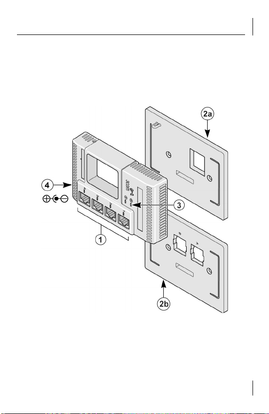
The following diagram shows the front view of the NJ95 and
both the Universal (2a) and Manufacturer Specific (2b) wall
plates. (see descriptions below)
Figure 1: NJ95 Feature Description
3
Page 10

User Guide
1 NJ95 Main Unit Allow up to four devices to be connected to the
network.
2a Universal Wall
Plate
Used to mount the main unit – pass through “wall
plate” and non manufacturer-specific.
(Included)
2b Manufacturer-
Specific Wall Plate
(purchased
separately – For
available plates see
www.3Com.com/
products and
Appendix E)
Used to Mount the Main Unit – Mount the
specific connectors on the Wall Plate. One of the
connectors would serve to connect the switched
ports to the Network.
The second connector referred to as an optional
port bypasses the functionality of the switch.
Allows connection to a separate network segment
or to an analog or digital PBX telephone network
3 LEDs Indicates network connection status.
Indicates NJ95 power status.
4 Power Socket NJ95 can be powered from a local power supply
(available for purchase from 3Com); required if
your network does not support Power Over
Ethernet (PoE).
4
Page 11
3. Installing the NJ95 Network Jack
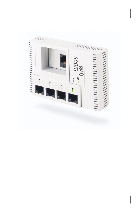
3. Installing the NJ95 Network Jack
Figure 2: NJ95 Network Jack Main Unit
1
Install the Universal “wall plate” or Manufacturer-specific
“wall plate”.
2
Mount the NJ95 Main unit on the Universal or
Manufacturer-specific “wall plate”.
3
Set up the power supply (Appendix C).
5
Page 12
User Guide
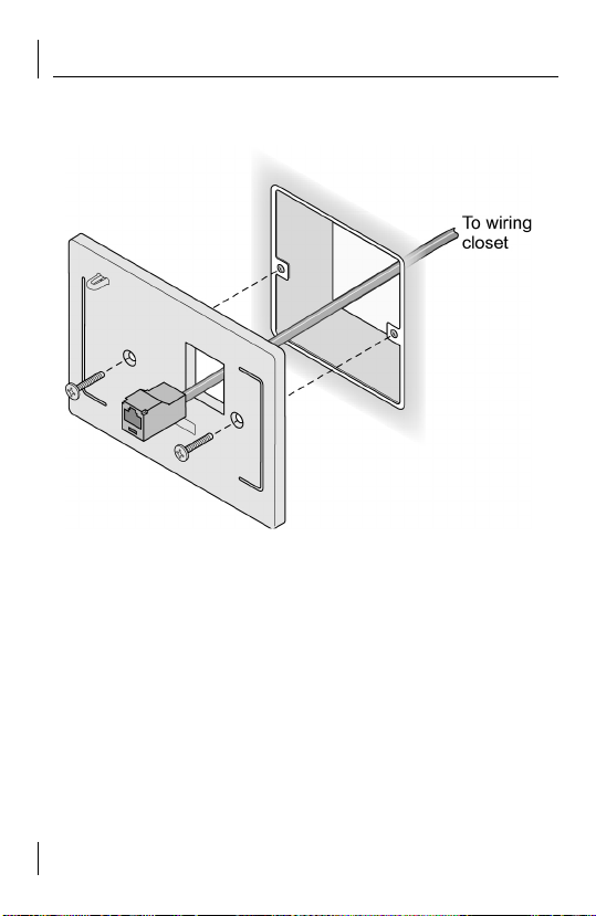
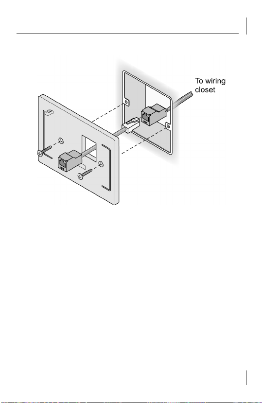
1a. Installing the Universal wall plate
Figure 3a: Installing the Universal Wall Plate
1
Thread the RJ-45 Connector attached to the wiring closet
cable through the opening in the Universal wall plate (Fig.
3a).
or
If necessary connect the coupler cable (Male RJ-45) to the
female RJ-45 connector attached to the Network cable and
thread it through the Universal wall plate (Fig. 3b).
6
Page 13
3. Installing the NJ95 Network Jack
Figure 3b: Installing the Universal Wall Plate (with Coupler Cable)
2
Mount the Universal wall plate to the Outlet box with the
screws provided.
7
Page 14
User Guide
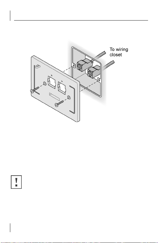
1b. Installing the Manufacturer-specific wall plate
Figure 4: Installing the Manufacturer-specific Wall Plate
1
Mount the manufacturer-specific connectors (which are
connected to the network cabling) on the manufacturerspecific wall plate.
2
Mount the manufacturer-specific wall plate to the Outlet
box with the screws provided.
CAUTION:
When the Wall plate is mounted, make sure
there is enough space inside of the junction box for an
acceptable bend radius on the cable.
8
Page 15
3. Installing the NJ95 Network Jack
2a. Mount the NJ95 Main unit on the Universal or
Manufacturer-specific wall plate.
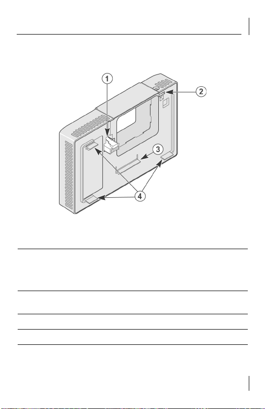
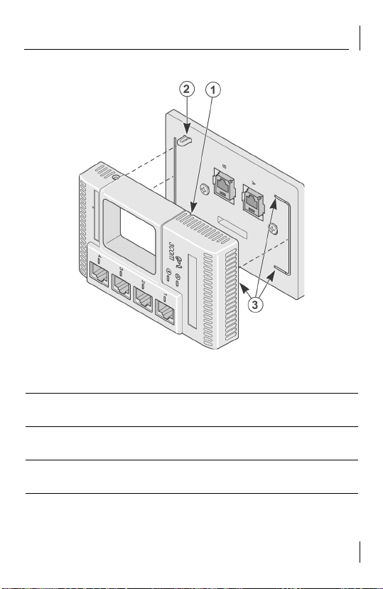
Figure 5: Rear view of NJ95
1 Ethernet Uplink port Connects the NJ95 to the network.
Make sure the port on the network switch to
which the NJ95 is connected is configured as a
standard MDI port.
2 Screw Tab Guide Used to align and retain the Main unit to the Wall
3 Main Latch Used to retain the Main unit to the Wall Plate
4 Alignment Tabs Used to align the Main unit to the Wall plate
Plate
9
Page 16
User Guide
2b. Mounting the NJ95 Main unit to the wall plate
Figure 6a: Mounting the NJ95 Main unit to the Universal Wall plate
10
Page 17
3. Installing the NJ95 Network Jack
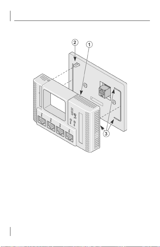
Figure 6b: Mounting the NJ95 to the Manufacturer-specific Wall plate
1 Groove for RJ-45
Jack release
Insert a pin through the groove to release the RJ45 plug
2 Screw Tab Used to align and retain the main unit to the wall
plate
3 Slots for Alignment
Align tabs on main unit to the wall plate slots
Tabs
11
Page 18
User Guide
1
Connect the main unit RJ-45 plug into the female RJ-45
connector at the end of the wiring closet cable/coupler
cable (Universal wall plate) or align it with the right most RJ45 connector (Manufacturer-specific wall plate).
2
Align the Screw Tab (Item #2) with the opening in the main
unit.
3
Align the Alignment Tabs on the main unit with the slots
(Item #3) in the Wall plate.
4
Snap the Main unit into the Wall plate).
2c. Fastening the NJ95
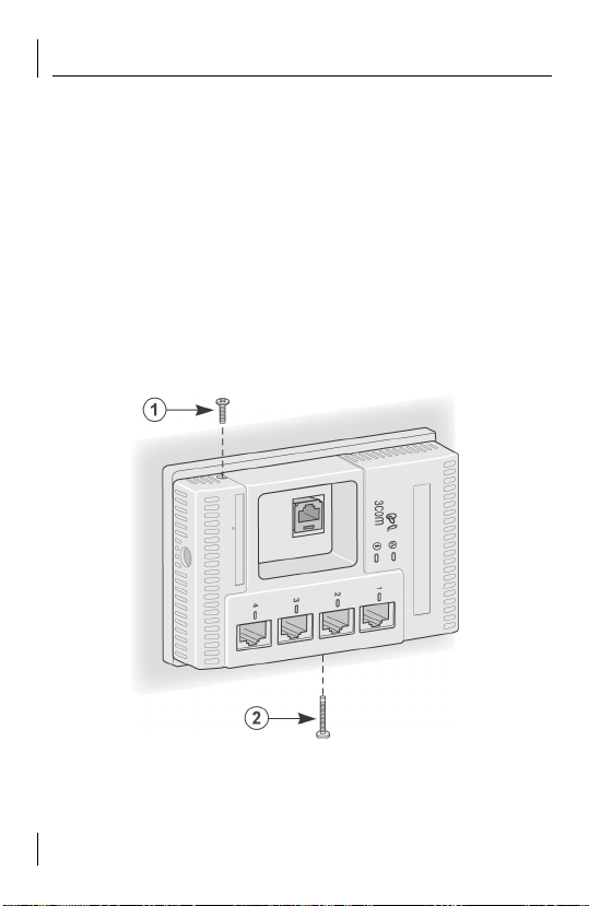
Figure 7: Securing the NJ95 Main unit to the Wall plate
12
Page 19

3. Installing the NJ95 Network Jack
1 Retaining Screw Retain the Main unit to the Wall plate
2 Main Latch Fastener Locks in the Main latch
1
Screw in the Retaining Screw (Item #1)
2
Secure the Main Latch Fastener (Item #2)
NOTE:
Make sure the vents along the edges of the NJ95
faceplate are clear of any obstructions.
CAUTION:
Make sure that you have sufficient clearance
on all sides to access release points, retaining screw, and
fastener.
13
Page 20

User Guide
3. Set up the power supply
Selecting the power scheme and installing it:
See Appendix C: Setting up the Power Supply (p 23).
You can verify the NJ95 Network Jack Installation by checking
the LEDs.
LED Description
■
On—The NJ95 is connected to the network and a
link has been established.
■
Off—There is no connection to the network.
(LAN)
■
On—The NJ95 is receiving power (local or via the
network).
■
Off—The NJ95 is not receiving power.
(Power)
CAUTION:
Make sure the port on the wiring closet
switch to which the NJ95 is connected is configured as a
standard MDI port.
14
Page 21

4. Un-Installing the NJ95 Network Jack
4. Un-Installing the NJ95 Network Jack
Figure 8: Unfastening the NJ95 Main unit from the Wall plate
1
Unscrew the Retaining Screw (Item #1)
2
Release the Main Latch Fastener (Item #2).
15
Page 22

User Guide
Figure 9a: Removing the NJ95 from the Universal Wall plate
16
Page 23

4. Un-Installing the NJ95 Network Jack
Figure 9b: Removing the NJ95 from the Manufacturer-specific Wall plate
3
Insert a pin (paper clip) along the groove (Item #1) to
release the RJ-45 plug.
4
Pull the Main unit away from the Wall plate.
17
Page 24

User Guide
18
Page 25

Appendix A: Detail Description of NJ95
Appendix A: Detail Description of NJ95
The NJ95 is a 4-port, un-managed Fast Ethernet switch that fits
into most standard data port openings. The NJ95 allows up to
four networking devices, such as computers, printers, Voice over
IP (VoIP) telephones, and scanners, to be connected to the
network via one Ethernet port. An optional connector is available
that allows an additional device to be connected to a separate
network segment through the same NJ95.
The NJ95 needs no software to operate and requires no
configuration. All ports feature 10/100 Mbps auto-negotiation,
which configures the NJ95 for 10 Mbps or 100 Mbps
connections automatically.
Power to the NJ95 can be provided in one of the following ways:
■
Power over Ethernet using an Integrated Switch
network via an integrated switch that supports IEEE
802.3af-compatible Power Over Ethernet (also known as Inline power, is a feature that provides power through an
Ethernet cable, allowing a device to receive both data and
power from the same network cable). See “Using an
Integrated Switch with Power over Ethernet” on page 24.
■
Power over Ethernet using a Midspan solution
network via an optional Multi-port or Single-port Ethernet
power supply. See “Using a Multi-port Ethernet Power
Setting up the Power Supply” on page 25 or “Using a
Single-port Ethernet Power Setting up the Power Supply”
on page 27.
: Over the
: Over the
19
Page 26

User Guide
■
Local Power Supply
: Locally via an optional local power
supply. See “Using the 3Com Local Power Supply” on page
28.
Connecting Devices to the NJ95
After the NJ95 is installed, connect your networking devices
(such as computers, printers, etc.) to any of the four switched
ports on the front of the NJ95. If you installed the manufacturerspecific wall plate, you can connect to another device to the
optional port.
20
Page 27

Appendix B: Wall Plate Dimensions
Appendix B: Wall Plate Dimensions
Make sure the wall or cubicle opening where the NJ95 is being
installed complies with the relevant standard, as described
below.
British Standard Institute (BSI) – BS 4664:1970
Figure 10: Wall Plate Dimensions - Two hole
21
Page 28

User Guide
There are instances where you would have a four hole outlet
box, where the wall plate can be oriented Horizontally or
Vertically. Such an instance is described below:
Figure 11: Wall Plate Dimensions - Four hole
22
Page 29

Appendix C: Setting up the Power Supply
Appendix C: Setting up the Power Supply
Power to the NJ95 can be supplied one of the following ways:
■
Over the network via an integrated switch that supports
Power Over Ethernet.
■
Over the network via a multi-port Ethernet power supply.
■
Over the network via a single-port Ethernet power supply.
■
Locally via a 3Com local power supply.
Before you begin the installation, determine which type of power
supply the NJ95 will use.
NOTE:
For a list of power supplies that support the
NJ95, go to www.3com.com/.
23
Page 30

User Guide
Using an Integrated Switch with Power Over Ethernet
You must have a switch on the network that provides Power
over Ethernet, compliant to the IEEE 802.3af standard.
Figure 12: Using an Integrated Switch with Power over Ethernet
24
Page 31

Appendix C: Setting up the Power Supply
Using a Multi-port Ethernet Power Supply
To use a multi-port Ethernet power supply, you must connect the
power supply to your network, as shown in figure 13.
The multi-port Ethernet power supply from 3Com connects to an
existing Ethernet or Fast Ethernet infrastructure with standard
Category 5 or Category 5e UTP cabling, and powers up to 24
NJ95 Network Jacks. See “Obtaining Optional Components” in
appendix E for ordering information. For complete installation
instructions, see the multi-port Ethernet power supply
documentation.
25
Page 32

User Guide
Figure 13: Using a Multi-port Ethernet Power Supply
26
Page 33

Appendix C: Setting up the Power Supply
Using a Single-port Ethernet Power Supply
To use a single-port Ethernet power supply, connect the power
supply to the network hub or switch and to the NJ95, as shown
in figure 14. See “Obtaining Optional Components” in Appendix
E for ordering information. For complete installation instructions,
see the single-port Ethernet power supply documentation.
Figure 14: Using a Single-port Ethernet Power Supply
27
Page 34

User Guide
Using the 3Com Local Power Supply
If your network does not support Power Over Ethernet, or if you
are not using a single-port or multi-port Ethernet power supply,
you must purchase a local power supply from 3Com (see
“Obtaining Optional Components” in Appendix E). To use the
local power supply, make sure you have an electrical outlet near
the site where the NJ95 will be installed.
Figure 15: Using the 3Com Local Power Supply
28
Page 35

Appendix C: Setting up the Power Supply
1
Plug the power cable into the Network Jack
2
Route the power cable through the stain relief fixture
located on the wall plate
3 Secure the local power supply and cable to the wall
4 Plug the local power supply into the power source
NOTE: Completing these procedures in sequence will
reduce issues during the installation process.
CAUTION: ONLY use the local power supply available
from 3Com. Failure to do so may result in damage to the
NJ95 Network Jack, or may result in a hazardous
situation.
29
Page 36

User Guide
30
Page 37

Appendix D: Specifications
Hardware
NJ95 Power
consumption
Network Interface
10 Mbps Ethernet
10BASE-T
100 Mbps Ethernet
100BASE-TX
5 watts (max)
Ethernet IEEE 802.3 industry standard for
a 10 Mbps baseband CSMA/CD local area
network
Ethernet IEEE 802.3u industry standard for
a 100 Mbps baseband CSMA/CD local area
network
Appendix D: Specifications
31
Page 38

User Guide
Performance
Auto-negotiation Communication speed (10 Mbps or 100 Mbps)
and duplex mode (full or half) is determined
through auto-negotiation with the attached
devices. The NJ95 attempts to negotiate the
fastest connection possible (100 Mbps fullduplex).
Environment
Operating temperature 32° to 95° F (0° to 35° C)
Storage temperature -22
˚ to 194˚ F (-3˚- to 90˚ C)
Operating humidity 10-90% noncondensing
Storage humidity 10-90% noncondensing
Operating Altitude 8,000 ft
Storage Altitude 20,000 ft
Standards Conformance
IEEE 802.3 10BASE-T, 100BASE-TX and auto-negotiation
Power Over Ethernet: IEEE 802.3af
Power Prioritization: 802.1p (QoS)
32
Page 39

Appendix D: Specifications
Features
Power Over Ethernet Compatible with IEEE 802.3af
Local power supply Required for networks that do not support Power
Over Ethernet
Voice Over IP (VoIP) Compatible with VoIP standard.
33
Page 40

User Guide
34
Page 41

Appendix E: Obtaining Optional Components
Appendix E: Obtaining Optional Components
The NJ95 works with the following optional components.
Updated information is available online at www.3com.com/
products.
Component Purpose 3C Number(s)
Wall plates For installing manufacturer specific
Single-port
Ethernet power
supply
(Uses Spare
Pairs)
Multi-port
Ethernet power
supply
(Uses Spare
Pairs)
Local power
supply
connectors and mounting the Main
Unit.
For providing Power Over Ethernet
to power a single NJ95.
For providing Power Over Ethernet
to power up to 24 NJ95s.
For locally powering a single NJ95;
required if your network does not
support Power Over Ethernet.
3CNJWP
3CNJWP-AV
3CNJWP-KR
3CNJPSE
3CNJPSE24
3CNJPSL
35
Page 42

User Guide36Appendix F: Setting up the Network Cabling at Your Site
Page 43

Appendix F: Setting up the Network Cabling at
Your Site
The network cabling at your site (from the wiring closet to the
wall or cubicle opening) may already be installed. If it is not,
install the cabling following these general guidelines.
CAUTION: It is recommended that a professional cable
installer perform these procedures. Be sure to adhere to
local safety and regulatory codes during the cable
installation.
1 Connect one end of an Ethernet cable to your network.
Usually, this connection is done in a network wiring closet,
via the patch panel.
2 Terminate the other end of the cable at the location where
the NJ95 is being installed using a female RJ-45 connector.
Refer to the connector manufacturer’s instructions for
terminating the cable. Be sure to test the connector and
verify it is working.
To ensure proper horizontal cabling functionality, adhere to the
following network cabling standards during installation:
■ ANSI/TIA/EIA-568 Commercial Building Telecommunications
Cabling Standard
■ ANSI/TIA/EIA-569 Commercial Building Standard for
Telecommunications Pathways and Spaces
■ British Standard Institute (BSI): BS 4664:1970
■ DIN
37
Page 44

User Guide
38
Page 45

Appendix G: Troubleshooting the NJ95
Appendix G: Troubleshooting the NJ95
If you encounter problems with the NJ95:
■ Verify the NJ95 is receiving power by viewing the Power
LED (it should be lit). If the Power LED is not lit, make sure:
■ The other end of the network cable is plugged into a
system that provides Power over Ethernet according to
IEEE 802.3af, if using Power over Ethernet.
■ The Local Power Supply is plugged into the NJ95 and
into a working electrical outlet, if using Local power
supply.
■ Verify the NJ95 is connected to the network properly by
viewing the Link LED (it should be lit). If the Link LED is not
lit, make sure the network cable:
■ Is terminated properly. Refer to the connector
manufacturer’s instructions for terminating the cable. Be
sure to test the connector and verify it is working.
■ Has a valid connection to the network.
■ Adheres to proper length and cabling specifications for
your network.
■ Make sure the port on the switch to which the NJ95 is
connected is configured as a standard MDI-X port. Make
sure all cables connecting the NJ95 to the patch panel are
straight-through cables (not crossover cables).
39
Page 46

User Guide
■ Verify that the DIP Switch settings are all set to OFF:
40
Page 47

Appendix H: Contacting Technical Support
Appendix H: Contacting Technical Support
3Com provides easy access to technical support information
through a variety of services. This section describes these
services. Information contained in this section is correct at time
of publication. For the most recent information, 3Com
recommends that you access the 3Com Corporation World Wide
Web site: www.3com.com.
90 Day Free Installation Support
3Com provides free installation and troubleshooting telephone
support for this product for 90 days from the date of purchase.
Hours of operation are subject to change. See “Support from
3Com” on page 43.
Online Technical Services
3Com offers worldwide product support 24 hours a day, 7 days
a week, through the following online systems:
■ World Wide Web site
■ 3Com Knowledgebase Web Services
■ 3Com FTP site
World Wide Web Site To access the latest networking
information on the 3Com Corporation World Wide Web site,
enter this URL into your Internet browser: http://
www.3com.com/. This service provides access to online support
information, such as technical documentation and a software
library, as well as support options that range from technical
education to maintenance and professional services.
41
Page 48

User Guide
3Com Knowledgebase Web Services This interactive tool
contains technical product information compiled by 3Com expert
technical engineers around the globe. Located on the World
Wide Web at http:// knowledgebase.3com.com, this service gives
all 3Com customers and partners complementary, around-theclock access to technical information on most 3Com products.
3Com FTP Site Download drivers, patches, software, and MIBs
across the Internet from the 3Com public FTP site. This service is
available 24 hours a day, 7 days a week. To connect to the 3Com
FTP site, enter the following information into your FTP client:
■ Host name: ftp.3com.com
■ User name: anonymous
■ Password: <your Internet e-mail address>
NOTE: You do not need a user name and password with
Web browser software, such as Netscape Navigator and
Microsoft Internet Explorer.
42
Page 49

Appendix H: Contacting Technical Support
Support from Your Network Supplier
If you require additional assistance, consult your network
supplier. Many suppliers are authorized 3Com service partners
who are qualified to provide a variety of services, including
network planning, installation, hardware maintenance,
application training, and support services.
When you contact your network supplier for assistance, have the
following information ready:
■ Product model name, part number, and serial number
■ A list of system hardware and software, including revision
levels
■ Diagnostic error messages
■ Details about recent configuration changes, if applicable
If you are unable to consult your network supplier, see the
following section on how to contact 3Com.
Support from 3Com
If you are unable to obtain assistance from the 3Com online
technical resources or from your network supplier, 3Com offers
technical telephone support services. To find out more about
your support options, call the 3Com technical telephone support
phone number: UK- 0870 909 3266; DE- 01805 404 747.
43
Page 50

User Guide
When you contact 3Com for assistance, have the following
information ready:
■ Product model name, part number, and serial number
■ A list of system hardware and software, including revision
levels
■ Diagnostic error messages
■ Details about recent configuration changes, if applicable
Country Telephone #
Austria 01 79567124
Belgium (Flemish) 070 700000
Belgium (French) 070 700770
Denmark 70107289
Finland 01080-2783
France 0825 809 622
Germany 01805 404 747
Hungary 06800 14466
Ireland 1800 509359
Israel 1800 9432632
Italy 199 161346
Luxembourg 800 29880
Netherlands 0900 777 7737
44
Page 51

Appendix H: Contacting Technical Support
Country Telephone #
Norway 815 33 047
Poland 00800 4411357
Portugal 707 200 123
South Africa 0800 991196
Spain 9 021 60455
Sweden 0771114453
Switzerland 0848850112
UK 0870 909 3266
All Other Countries +44 1442 435529
Returning Products for Repair Before you send a product
directly to 3Com for repair, you must first obtain an
authorization number. Products sent to 3Com without
authorization numbers will be returned to the sender unopened,
at the sender’s expense. To obtain an authorization number, call:
UK- 0870 909 3266; DE- 01805 404 747.
45
Page 52

User Guide
46
Page 53

Limited Warranty and Regulatory
Compliance Information
3Com Corporation Limited Warranty
This warranty applies to customers located in the United States, Australia, Canada
(except Quebec), Ireland, New Zealand, U.K., and other English language countries,
and countries for which a translation into the local language is not provided
3Com® NJ95
HARDWARE
3Com warrants to the end user (“Customer”) that this hardware product will be
substantially free from material defects in workmanship and materials, under normal
use and service, for the following length of time from the date of purchase from
3Com or its authorized reseller:
Limited Lifetime, for as long as the original Customer owns the product or for 5 years
after product discontinuance, whichever occurs first (not transferable to a
subsequent end user). FOR NON-US CUSTOMERS: Where a limited lifetime warranty
is not permitted by local law, a 10 year warranty period shall be given by 3Com. The
duration of this warranty shall be modified where necessary to meet any minimum
warranty period required by law.
3Com’s sole obligation under this express warranty shall be, at 3Com’s option and
expense, to repair the defective product or part, deliver to Customer an equivalent
product or part to replace the defective item, or if neither of the two foregoing
options is reasonably available, refund to Customer the purchase price paid for the
defective product. All products that are replaced will become the property of 3Com.
Replacement products or parts may be new or reconditioned. 3Com warrants any
replaced or repaired product or part for ninety (90) days from shipment, or the
remainder of the initial warranty period, whichever is longer.
OBTAINING WARRANTY SERVICE
Customer must contact a 3Com Corporate Service Center or an Authorized 3Com
Service Center within the applicable warranty period to obtain warranty service
authorization. Dated proof of purchase from 3Com or its authorized reseller may be
required. A User Service Order (USO), Return Material Authorization (RMA) or Service
Repair Order (SRO) number will be issued. This number must be marked on the
outside of the package sent to 3Com’s Corporate Service Center. The product must
Page 54

Limited Warranty and Regulatory Compliance Information
be packaged appropriately for safe shipment and sent prepaid. It is recommended
that returned products be insured or sent by a method that provides for tracking of
the package. Responsibility for loss or damage does not transfer to 3Com until the
returned item is received by 3Com. 3Com will retain risk of loss or damage until the
item is delivered to Customer. For non-US Customers, the word 'prepaid' shall be
omitted where this requirement is not permitted by law. The allocation of
responsibility for loss or damage stated shall be subject to any mandatory legal
requirements. 3Com shall not be responsible for any software, firmware,
information, or memory data of Customer contained in, stored on, or integrated
with any products returned to 3Com for repair, whether under warranty or not.
Page 55

Limited Warranty and Regulatory Compliance Information
WARRANTIES EXCLUSIVE, WARRANTY DISCLAIMER
TO THE FULL EXTENT ALLOWED BY LAW, THE FOREGOING WARRANTIES AND
REMEDIES ARE EXCLUSIVE AND ARE IN LIEU OF ALL OTHER WARRANTIES, TERMS
OR CONDITIONS, EXPRESS OR IMPLIED, EITHER IN FACT OR BY OPERATION OF LAW,
STATUTORY OR OTHERWISE, INCLUDING, WITHOUT LIMITATION, WARRANTIES,
TERMS OR CONDITIONS OF MERCHANTABILITY, FITNESS FOR A PARTICULAR
PURPOSE, SATISFACTORY QUALITY, CORRESPONDENCE WITH DESCRIPTION,
NONINFRINGEMENT AND QUIET ENJOYMENT, ALL OF WHICH ARE EXPRESSLY
DISCLAIMED. 3COM NEITHER ASSUMES NOR AUTHORIZES ANY OTHER PERSON TO
ASSUME FOR IT ANY OTHER LIABILITY IN CONNECTION WITH THE SALE,
INSTALLATION, MAINTENANCE OR USE OF THIS PRODUCT.
3COM SHALL NOT BE LIABLE UNDER THIS WARRANTY IF ITS TESTING AND
EXAMINATION DISCLOSE THAT THE ALLEGED DEFECT OR MALFUNCTION IN THE
PRODUCT DOES NOT EXIST OR WAS CAUSED BY CUSTOMER'S OR ANY THIRD
PERSON'S MISUSE, NEGLECT, IMPROPER INSTALLATION OR TESTING,
UNAUTHORIZED ATTEMPTS TO OPEN, REPAIR OR MODIFY THE PRODUCT, OR ANY
OTHER CAUSE BEYOND THE RANGE OF THE INTENDED USE, OR BY ACCIDENT, FIRE,
LIGHTNING, POWER CUTS OR OUTAGES, OTHER HAZARDS, OR ACTS OF GOD.
LIMITATION OF LIABILITY
TO THE FULL EXTENT ALLOWED BY LAW, 3COM ALSO EXCLUDES FOR ITSELF AND
ITS LICENSORS AND SUPPLIERS ANY LIABILITY, WHETHER BASED IN CONTRACT OR
TORT (INCLUDING NEGLIGENCE), FOR INCIDENTAL, CONSEQUENTIAL, INDIRECT,
SPECIAL, OR PUNITIVE DAMAGES OF ANY KIND, OR FOR LOSS OF REVENUE OR
PROFITS, LOSS OF BUSINESS, LOSS OF INFORMATION OR DATA, OR OTHER
FINANCIAL LOSS ARISING OUT OF OR IN CONNECTION WITH THE SALE,
INSTALLATION, MAINTENANCE, USE, PERFORMANCE, FAILURE, OR INTERRUPTION
OF ITS PRODUCTS, EVEN IF 3COM OR ITS AUTHORIZED RESELLER HAS BEEN
ADVISED OF THE POSSIBILITY OF SUCH DAMAGES, AND LIMITS ITS LIABILITY TO
REPAIR, REPLACEMENT, OR REFUND OF THE PURCHASE PRICE PAID, AT 3COM'S
OPTION. THIS DISCLAIMER OF LIABILITY FOR DAMAGES WILL NOT BE AFFECTED IF
ANY REMEDY PROVIDED HEREIN SHALL FAIL OF ITS ESSENTIAL PURPOSE.
Some countries, states, or provinces do not allow the exclusion or limitation of
implied warranties or the limitation of incidental or consequential damages for
certain products supplied to consumers, or the limitation of liability for death or
personal injury, so the above limitations and exclusions may be limited in their
application to you. When the implied warranties are not allowed to be excluded in
their entirety, they will be limited to the duration of the applicable written warranty.
This warranty gives you specific legal rights which may vary depending on local law.
Page 56

Limited Warranty and Regulatory Compliance Information
GOVERNING LAW
This Limited Warranty shall be governed by the laws of the State of
California, U.S.A., and by the laws of the United States, excluding their
conflicts of laws principles. The United Nations Convention on Contracts for
the International Sale of Goods is hereby excluded in its entirety from
application to this Limited Warranty.
3Com Corporation
5400 Bayfront Plaza
P.O. Box 58145
Santa Clara, CA 95052-8145
(408) 326-5000
Rev. 6/14/01
v8.3
Page 57

Limited Warranty and Regulatory Compliance Information
FCC Compliance
This device complies with part 15 of the FCC Rules. Operation is subject to the
following two conditions: (1) This device may not cause harmful interference, and (2)
this device must accept any interference received, including interference that may
cause undesired operation.
FCC Class A Verification Statement
WARNING: This equipment has been tested and found to comply with the limits for
a Class A digital device, pursuant to Part 15 of the FCC Rules, and the Canadian
Department of Communications Equipment Standards entitled, “Digital Apparatus,”
ICES-003. These limits are designed to provide reasonable protection against harmful
interference in a commercial installation. This equipment generates, uses and can
radiate radio frequency energy and, if not installed and used in accordance with the
instructions, may cause harmful interference to radio communications. Operation of
this equipment in a residential area is likely to cause harmful interference, in which
case, the user will be required to correct the interference at the user’s own expense.
Changes or modifications not expressly approved by 3Com could void the user’s
authority to operate this equipment.
FCC Declaration of Conformity
We declare under our sole responsibility that the
Model: Description:
NJ95 Network Jack
to which this declaration relates, is in conformity with the following standards or
other normative documents:
■ ANSI C63.4-1992 Methods of Measurement
Federal Communications Commission 47 CFR Part 15, subpart B
Industry Canada (IC) Compliance Statement
This Class A digital apparatus complies with Canadian ICES-003.
Cet appareil numérique de la classe A est conform à la norme NMB-003 du Canada.
Page 58

European Union Declaration of Conformity
This product is in compliance with the essential requirements and other relevant
provisions of Directives 73/23/EEC and 89/336/EEC.
3Com Corporation, 5400 Bayfront Plaza, P.O. Box 58145, Santa Clara, CA 95052-8145
09-2264-000
Page 59

Page 60

3Com Corporation
P.O. Box 58145
5400 Bayfront Plaza
Santa Clara, CA 95052-8145
U.S.A.
www.3com.com
09-2264-000
Printed in the U.S.A.
 Loading...