

Page 1

F F I C E
®
U S E R
U I D
16710.bk : FRONT.FRM Page 1 Tuesday, October 7, 1997 11:38 AM
Part No.
DUA1671-0AAA03
O
3C16710
G
O N N E C T
C
E
H
U B
8/TPM
Published
October 1997
Page 2

16710.bk : FRONT.FRM Page 2 Tuesday, October 7, 1997 11:38 AM
3Com Corporation
© 3Com Technologies, 1997. All rights reserved. No part of this
documentation may be reproduced in any form or by any means
or used to make any derivative work (such as translation,
transformation, or adaptation) without permission from 3Com
Technologies. 3Com Technologies reserves the right to revise this
documentation and to make changes in content from time to time
without obligation on the part of 3Com Technologies to provide
notification of such revision or change. 3Com Technologies
provides this documentation without warranty of any kind, either
implied or expressed, including, but not limited to, the implied
warranties of merchantability and fitness for a particular purpose.
3Com may make improvements or changes in the product(s)
and/or the program(s) described in this documentation at any
time.
UNITED STATES GOVERNMENT LEGENDS:
If you are a United States government agency, then this
documentation and the software described herein are provided to
you subject to the following restricted rights:
For units of the Department of Defense:
Legend:
Use, duplication or disclosure by the Government is
subject to restrictions as set forth in subparagraph (c) (1) (ii) for
restricted Rights in Technical Data and Computer Software clause
at 48 C.F.R. 52.227-7013. 3Com Technologies, c/o 3Com Centre,
BoundaryWay, Hemel Hempstead, Herts, HP27YU, UK.
■
5400 Bayfront Plaza
Restricted Rights
■
Santa Clara, California
For civilian agencies:
or disclosure is subject to restrictions set forth in subparagraph (a)
through (d) of the Commercial Computer Software - Restricted
Rights Clause at 48 C.F.R. 52.227-19 and the limitations set forth in
3Com Corporation’s standard commercial agreement for the
software. Unpublished rights reserved under the copyright laws of
the United States.
If there is any software on removable media described in this
documentation, it is furnished under a license agreement included
with the product as a separate document, in the hard copy
documentation, or on the removable media in a directory file
named LICENSE.TXT. If you are unable to locate a copy, please
contact 3Com and a copy will be provided to you.
Unless otherwise indicated, 3Com registered trademarks are
registered in the United States and may or may not be registered
in other countries.
3Com, OfficeConnect, NetAge, SmartAgent and Transcend are
registered trademarks of 3Com Corporation. 3ComFacts and
Ask3Com are service marks of 3Com Corporation .
CompuServe is a registered trademark of CompuServe, Inc.
Windows
is a registered trademark of Microsoft Corporation. VT100 is a
registered trademark of Digital Equipment Corporation.
■
95052-8145
Restricted Rights Legend:
Use, reproduction
Other brand and product names may be registered trademarks or
trademarks of their respective holders.
Page 3

C O N T E N T S I M P O R T A N T S A F E T Y I N F O R M A T I O N W I C H T I G E S I C H E R H E I T S H I N W E I S E L’ I N F O R M A T I O N D E S É C U R I T É I M P O R T A N T E Y O U R H U B A D D R E S S E S A B O U T T H I S G U I D E
I N T R O D U C T I O N
C R E A T I N G Y O U R N E T W O R K
S
A B O U T N E T W O R K M A N A G E M E N T
16710.bk : 16710.TOC Page iii Tuesday, October 7, 1997 11:38 AM
LEDs and Ports 2-1
Before You Start 2-4
Posi t ion ing the Office Connect H ub 2-5
Using the Rubber Feet and Stacking Cl ips 2-6
Wall Mounting the Office Connect H ub 2-7
Connecting Workstations and Other Equipment to Your
Hub 2-7
Conne cti ng Office Connect H ubs Together 2-8
pot Checks 2-11
Introduction 1
How to Use This Guide 1
Conventions 2
Networking Terminology 1-2
3Com Network Management 3-1
Why Manage Your Hub? 3-2
Connecting to the Hub and Managing 3-3
Managing Through the Console Port 3-4
Managing Over the Network 3-6
Remote Management Service 3-7
Page 4

M A N A G I N G Y O U R H U B U S I N G Q U I C K C O N F I G M A N A G E R
A D D I T I O N A L M A N A G E M E N T U S I N G
S
Co
16710.bk : 16710.TOC Page iv Tuesday, October 7, 1997 11:38 AM
Setting Up a Resilient Link Pair 4-34
Using the Hub to Monitor Other Devices 4-37
Additional Management 4-39
Installing Quick Config Manager 4-1
Installation Requirements 4-1
Installation Procedure 4-2
Running Quick Config Manager 4-2
Configuring Multiple Hubs 4-3
Quick Config Manager Window Map 4-3
Accessing the Hub 4-6
Giving the Hub an IP Address 4-7
Resetting the Hub 4-11
Initializing the Hub 4-11
Viewing the Hub 4-12
Displaying Information About the Hub 4-13
Setting Up the Alert LED 4-15
Monitoring 4-18
Monitoring Activity and Errors Statistics 4-19
Frame Types Statistics 4-21
Network Traffic Statistics 4-22
Network Errors Statistics 4-23
Configuring a Port 4-25
Hub Security 4-28
Configuring Security at Port Level 4-29
Configuring Security at Hub Level 4-31
Resilience 4-33
VT100 User Interface 5-1
Screens 5-1
Screen Components 5-2
Special Keystrokes 5-3
Repeater, Unit and Port Screens 5-4
creen Map 5-4
Getting Started 5-6
Main Banner 5-6
Logo n 5 -7
Main Menu 5-9
Logo ff 5 -9
Auto Logout 5-9
Configuring and Viewing Setup Information 5-10
Setting Up Traps 5-12
nnecting a Modem to t he Console Port 5-13
Configuring Local Security 5-15
Configuring Users 5-17
Creating Users 5-17
Editing Users 5-18
Deleting Users 5-19
Polling a Remote Device 5-19
VT100
Page 5

P R O B L E M S O L V I N G
Ap
D I M E N S I O N S
T A N D A R D S A N D C A B L I N G
A N D
D D R E S S E S
T E C H N I C A L S U P P O R T
I N D E X L I M I T E D L I F E T I M E W A R R A N T Y
T A T E M E N T
16710.bk : 16710.TOC Page v Tuesday, October 7, 1997 11:38 AM
Viewing Internal Version Numbers 5-20
Downloading a Software Upgrade 5-21
Isolating a Problem 6-1
Problems When Using Your Hub 6-2
Problems When Using Quick Config Manager 6-3
Problems When Using VT100 6-3
Problems When Using an IP/IPX- ba sed Ma nagement
plication 6-4
, S
Dimensions and Operating Environment A-1
BABT Approval (for U.K. Users Only) A-1
Standards A-1
Cabling A-2
10BASE-T A-2
Console Port A-3
IP
IP Addresses B-1
IPX A
Obtaining a Network Number B-2
How IP Addresses Work B-3
Assigning IP Addresses to a Small, Contained
Network B-5
IPX Addresses B-6
Online Technical Services C-1
World Wide Web Site C-1
3Com Bulletin Board Service C-1
3ComFacts Automated Fax Service C-2
3ComForum on CompuServe Online Service C-3
Support from Your Network Supplier C-4
Support from 3Com C-4
Returning Products for Repair C-6
EMC S
S
Page 6

16710.bk : 16710.TOC Page vi Tuesday, October 7, 1997 11:38 AM
Page 7

I M P O R T A N T
A F E T Y I N F O R M A T I O N
16710.bk : IMSAFETY.FRM Page 7 Tuesday, October 7, 1997 11:38 AM
S
WA RNI NG :
Warnings contain directions that you
must follow for your personal safety. Follow all
instructions carefully.
Please read carefully the following information
before installing the OfficeConnect® hub:
■
Exceptional care must be taken during installation
and removal of the unit.
■
Only stack the OfficeConnect hub with other
OfficeConnect units.
■
Only use the power adapter that is supplied with the
unit to ensure compliance with international safety
standards.
■
It is essential that the power outlet is located near
the unit and is accessible. You can only remove
power to the OfficeConnect hub by disconnecting
the power adapter from the unit or from the socket
outlet.
■
This unit operates under SELV conditions (Safety
Extra Low Voltage) according to IEC 950, the
conditions of which are maintained only if the
equipment to which it is connected is also
operational under SELV.
■
There are no user-replaceable fuses or
user-serviceable parts inside the hub. If you have a
physical problem with the unit that cannot be solved
with problem solving actions in this guide, contact
your supplier.
■
Disconnect the power adapter before moving the
unit.
WARNING: Twisted Pair RJ45 ports.
These are
shielded RJ45 data sockets. They cannot be used as
telephone sockets. Only connect RJ45 data
connectors to these sockets.
Page 8

I C H T I G E
I C H E R H E I T S H I N W E I S E
16710.bk : IMSAFETY.FRM Page 8 Tuesday, October 7, 1997 11:38 AM
W
S
ACHTUNG:
die Sie zur eigenen Sicherheit zu befolgen haben.
Lesen Sie bitte die folgenden Informationen
sorgfältig durch, bevor Sie den Hub einbauen:
■
Auf besondere Vorsicht muß während des Ein- und
Ausbaus des Hubs geachtet werden.
■
Stapeln Sie den Hub nur mit anderen OfficeConnect
Hubs zusammen.
■
Verwenden Sie nur das mit dem Hub mitgelieferte
Netzteil um die internationalen Sicherheitsstandards
zu erfüllen.
■
Die Netzsteckdose muß sich in unmittelbarer Nähe
des Hubs befinden und frei zugänglich sein. Sie
können den Hub nur spannungsfrei schalten, indem
Sie das Steckernetzteil aus der Netzsteckdose ziehen
oder die Verbindung zum Gerät unterbrechen.
Die Warnungen enthalten Anweisungen,
■
Dieser Hub arbeitet mit SELV-Spannung (Safety Extra
Low Voltage, Sicherheitskleinspannung) gemäß
IEC950. Diese Bedingungen werden nur eingehalten,
wenn die Geräte mit denen der Hub verbunden ist
ebenfalls mit SELV-Spannung arbeiten.
■
Es sind keine von dem Benutzer zu ersetzende oder
zu wartende Teile in dem Gerät vorhanden. Wenn Sie
ein Problem mit dem Hub haben, das nicht mittels
der Fehleranalyse in dieser Anleitung behoben
werden kann, setzen Sie sich mit Ihrem Lieferanten in
Verbindung.
■
Bevor der Hub ausgebaut wird ist das Netzteil zu
ziehen.
ACHTUNG: gedrehte paarfache RJ45 Anschlüsse.
Es sind abgeschirmte RJ45 Datenanschlußbuchsen.
Sie dürfen nicht als Telefonanschluß verwendet
werden. Verbinden Sie nur RJ45 Datenstecker mit
diesen Anschlüssen.
Page 9

L’ I N F O R M A T I O N D E
É C U R I T É I M P O R T A N T E
16710.bk : IMSAFETY.FRM Page 9 Tuesday, October 7, 1997 11:38 AM
S
AVERTISSEMENT:
Les avertissements contiennent
les instructions que vous devez suivre pour votre
sécurité personnelle. Suivre toutes les instructions
avec soin.
Veuillez lire à fond l’information suivante avant
d’installer le moyeu:
■
Le soin exceptionnel doit être pris pendant
l’installation et l’enlèvement du moyeu.
■
Seulement entasser le moyer avec les autres moyeux
OfficeConnects.
■
Seulement utiliser la pièce de raccordement
d’alimentation qui est fournie avec le moyeu pour
assurer la conformité avec les normes de sécurité
internationales.
■
C’est essentiel que le socle de prise de courant du
réseau soit localisé proche du moyeu et soit
accessible. Vous pouvez seulement enlever
l’alimentation au moyeu en débranchant la pièce de
raccordement d’alimentation de l’unité ou du socle
de prise de courant.
■
Ce moyeu fonctionne sous les conditiones SELV
(Sécurité du Voltage le plus Bas) d’après IEC950, les
conditions desquelles sont maintenues seulement si
le matériel à qui il est branché est aussi en
exploitation sous SELV.
■
Il n’y a pas de parties remplaceables par les
utilisateurs ou entretenues par les utilisateurs à
l’intérieur du moyeu. Si vous avez un problème
physique avec le moyeu qui ne peut pas être résolu
avec les actions de la résolution des problèmes dans
ce guide, contacter votre fournisseur.
■
Débrancher la pièce de raccordement d’alimentation
avant de remuer le moyeu.
AVERTISSEMENT: Les ports RJ45 de paire tordue.
Ceux-ci sont les socles de données RJ45 blindés. Ils ne
peuvent pas être utilisés comme socles de téléphone.
Seulement brancher les connecteurs de données RJ45
à ces socles.
Page 10

Y O U R
U B
D D R E S S E S
16710.bk : IMSAFETY.FRM Page 10 Tuesday, October 7, 1997 11:38 AM
H
Using Quick Config Manager, you can configure
address information for your hub, which affects the
way you can manage it. It is important that you note
down this information as you may need to enter it
when managing the hub again. Use this page to
note down your settings.
If you initialize the hub, the address settings are
retained to allow you to continue managing the
hub. If you want to return the hub to its default
address settings, you must enter them manually.
For information on configuring the hub’s address
settings, see “Giving the Hub an IP Address” on
page 4-7 .
A
Parameter Default
Device
Name
Emergency
Contact
Support
Contract
IP Address 0.0.0.0
Subnet
Mask
Serial Line
IP Address
Subnet
Mask
Router
IP Address
Manager
IP Address
3Com
3Com
3Com
0.0. 0.0
192.168.101.1
255.255.255.0
0.0.0.0
0.0.0.0
Your Setting
Page 11

A B O U T
H I S
U I D E
16710.bk : ABOUTGUI.FRM Page 1 Tuesday, October 7, 1997 11:38 AM
Introduction
This guide describes how to set up and manage the
OfficeConnect® Hub 8/TPM. The hub is ready for use
in your network. It does not require management to
get it working. Management simply allows you to
perform additional network functions, for example
monitoring your network and adding security.
This guide is written for users who are new to
networking. If you are going to manage your
network for the first time, it is possible you may
make mistakes. We have tried to identify the likely
errors you may make and have provided hints and
tips to help you recover from these situations. If you
are already familiar with network management, you
may be able to skip some of the information in this
guide and use the information given for reference
purposes.
T
G
How to Use This Guide
This table shows where to find specific information:
If you are looking for information on:
The hub and networking terms
Creating your network
What you can do with management and the
different ways you can manage your hub
Managing your hub using 3Com’s Transcend®
Quick Configuration Manager
Additional management using VT100
Problem solving
Dimensions, standards and cabling
Network addressing (IP/IPX)
The OfficeConnect product range, obtaining
technical support, and 3Com repair services
Turn to:
Chapter 1
Chapter 2
Chapter 3
Chapter 4
Chapter 5
Chapter 6
Appendix A
Appendix B
Appendix C
There is a Quick Reference Guide accompanying this
guide. It contains some useful information from this
guide which you may need to refer to regularly.
Page 12

2 A B O U T T H I S G U I D E
16710.bk : ABOUTGUI.FRM Page 2 Tuesday, October 7, 1997 11:38 AM
The text conventions that are used in this guide are:
Conventions
The icon conventions that are used in this guide are:
Icon
Type
Information Note Information notes call attention to
Caution
Warning
Description
important features or instructions.
Cautions alert you to personal
safety risk, system damage, or loss
of data.
Warnings alert you to the risk of
severe personal injury.
Convention
“Enter” vs. “Type”
Text represented as
screen display
Text represented as
commands
Keys
Italics
Description
When the word “enter” is used in this
guide, it means type something, then
press the Return or Enter key. Do not press
the Return or Enter key when an
instruction simply says “type.”
This typeface
displays that appear on your screen, for
example:
Enter the IP add ress:
This typeface
commands that you enter, for example:
191.0.0 .172
When specific keys are referred
text, they are called out by their labels,
such as “the Return key” or “the Escape
key,” or they may be shown as [Return] or
[Esc].
If two or more keys are to be pressed
simultaneously, the keys are linked with a
plus sign (+), for example:
Press [Ctrl]+[Alt]+[Del].
Italics
are used to denote
emphasis
.
is used to represent
is used to represent
to in the
new terms
or
Page 13
I N T R O D U C T I O N
3C om
16710.bk : GETSTART.FRM Page 1 Tuesday, October 7, 1997 11:38 AM
1
Welcome to the world of networking with 3Com ® .
In the modern business environment,
communication and sharing information is crucial.
Computer networks have proved to be one of the
fastest modes of communication but until now only
large businesses could afford the networking
advantage. The Office Connect® p roduct range from
changed this, bringing networks to the small
office.
The Office Connect Hub 8/TP M is ideal for creating a
small network. It is compact and attractively
designed for desktop use, and is part of the
Office Connect ra nge which neatly stack together
with clips, providing a host of facilities, for example
print sharing and a network fax. For information on
these products, see “3Com provides easy access to
technical support information through a variety of
services. This appendix describes these services.” on
page C-1 .
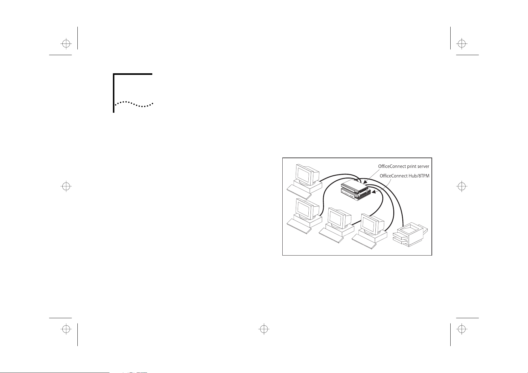
A single Office Connect hub allows you to create a
small network with up to eight workstations, as
shown in Figure 1-1 .
Figure 1-1 Small Network Featuring Office Connect H ub And
Optional Print Server
If you need to connect more workstations, simply
connect and clip another Office Connect h ub to form
Page 14

C H A P T E R
N T R O D U C T I O N
A
A
A
16710.bk : GETSTART.FRM Page 2 Tuesday, October 7, 1997 11:38 AM
1-2
a stack (each hub is a single repeater) . The
Office Connect Hub 8/TP M h as eight 10BASE-T ports
and a ninth 10BASE-2 (Coax) port. This guide helps
you get the most out of your hub .
1: I
Networking Terminology
Network
Local Area Network (LAN)
Ethernet
10BASE-T
10BASE-2
Network Loop
is a collection of workstations (for example,
IBM-compatible personal computers) and other
equipment (for example, printers), connected for the
purpose of exchanging information. Networks vary in
size, some are within a single room, others span
continents.
is a network, usually in an
office, that spans no more than a single site.
is a type of LAN, referring to the technology used to
pass information around the network.
is the name given to the Ethernet protocol that
runs over
hub uses
network.
is the name given to the Ethernet protocol that
runs over
equipment are connected by more than one path.
Your hub detects this and
of its ports to break the loop.
Twisted Pair (TP)
RJ45
type connectors for connecting your
Coaxial
occurs when two pieces of network
cable.
cable. The Office Connect
Partitions
(isolates) one
Page 15

A
A
16710.bk : GETSTART.FRM Page 3 Tuesday, October 7, 1997 11:38 AM
Segment
is the length of Ethernet cable connected to a
port, whether this cable is 10BASE-T, 10BASE-2
(Coax) , or other type. When you daisy-chain
equipment together with 10BASE-2 (Coax) cable,
of the cable forms a single segment.
Packets
are the units of information your workstations and
other equipment send to each other over the
network. A
Frame
is the data part of a packet. It is
the information that is seen by the hub.
Collisions
are a p art of normal Ethernet operation and occur
if two or more devices attempt to transmit at the
same time. A sudden sustained increase in the
number of collisions can indicate a problem with a
device, particularly if it is not accompanied by a
general increase in traffic. On coaxial segments an
increase in collisions can also indicate faulty cabling.
Device
is a term that is usually used to refer to a piece of
network equipment. Every device has a unique
address that is used to identify it on the network.
all
Networking Terminology
SNMP (Simple Network Management Protocol)
protocol that controls how a management station
gains information from a device. SNMP provides:
■
A set of rules that defin e how a m anagement
station can communicate with a device.
MIB (Management Information Base)
■
defines what information can be obtained from
the device by the management station. Every
SNMP-manageable device has a MIB, which is a
list of information about it.
■
Unsolicited messages called
Traps
, which work
differently to the usual request/reply
management communication. You can
configure a device so that it generates a trap if a
certain condition occurs, for example a port
partitioning. The trap is sent to the management
station to inform it of the occurrence.
1-3
is a
that
Page 16

C H A P T E R
N T R O D U C T I O N
I P.
A
16710.bk : GETSTART.FRM Page 4 Tuesday, October 7, 1997 11:38 AM
1-4
IP (Internet Protocol)
used to connect computers and data equipment into
computer networks. It is used on a large international
network called the
universities, government facilities, research
institutions and private companies.
Netware protocol that perfor ms a similar function to
SLIP (Serial Line Internet Protocol)
protocol over a serial line connection.
VT100
is a type of terminal which uses AS CII characters.
VT100 screens have a text-based appearance.
Tel ne t
is a network application which enables a workstation
to connect to a device as if it were a terminal, such as
VT100. It is provided as part of IP and is commonly
available with SNMP network management.
Modem
(Modulator-Demodulator) is a piece of equipment
used for transmitting computer data over telephone
lines.
1: I
is a data communication protocol
Internet
, which is composed of
IPX
allows you to run the IP
is a Novell
Page 17

C R E A T I N G
O U R
E T W O R K
16710.bk : CREYRNET.FRM Page 1 Tuesday, October 7, 1997 11:38 AM
2
All of the products in the Office Connect® r ange are
designed for ease of use. This chapter describes how
to use your Office Connect Hub 8/TP M to create your
network, and has information on:
■
The hub’s LEDs and ports
■
What you need to create your network
■
Where to site the hub
■
Using the rubber feet and stacking clips
■
Wall mounting the hub
■
Connecting your workstations and other equipment
to the hub
■
Connecting your hub to other Office Connect h ubs
Y
N
LEDs and Ports
■
■
■
■
■
■
The hub features diagnostic LEDs and easy to use
ports.
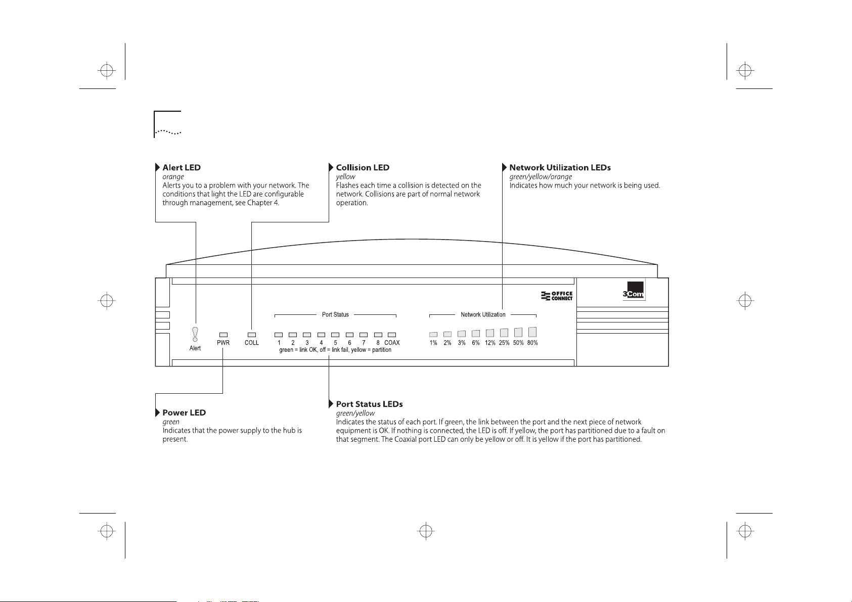
The LEDs are shown in Figure 2-1 , and are used for:
Showing you how the hub and its ports are
operating
Showing you how much your network is being used
Alerting you to a potential problem with your
network
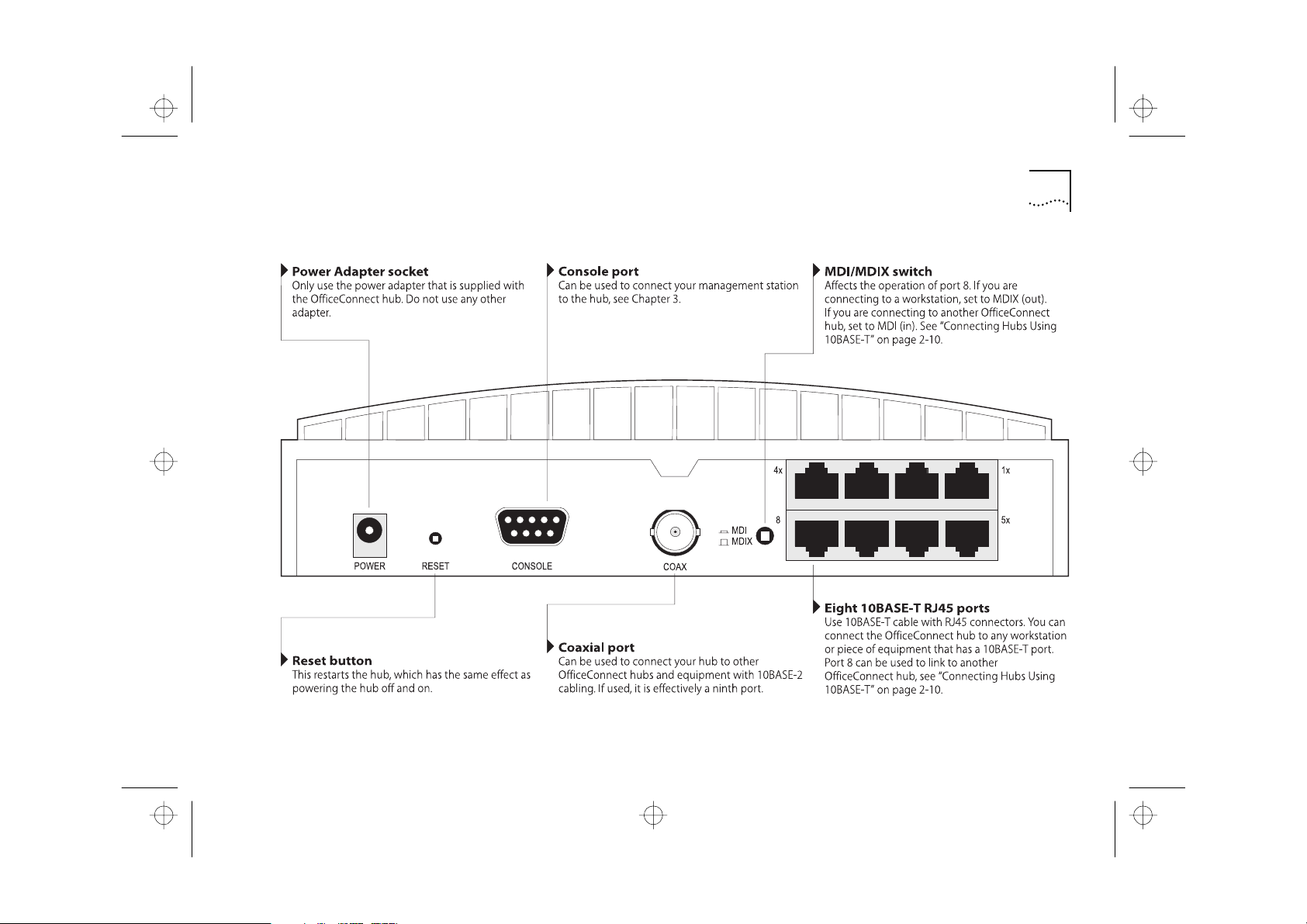
The ports are shown in Figure 2-2 , and are used for:
Connecting workstations and other equipment to
your hub
Connecting your hub to another Office Connect h ub
Connecting a management station to your hub
Figure 2-1 and Figure 2-2 also appear on the Quick
Reference Guide.
Page 18
C H A P T E R
R E A T I N G Y O U R N E T W O R K
16710.bk : CREYRNET.FRM Page 2 Tuesday, October 7, 1997 11:38 AM
2-2
2: C
Figure 2-1 The LEDs And How To U se Them
Page 19
16710.bk : CREYRNET.FRM Page 3 Tuesday, October 7, 1997 11:38 AM
LEDs and Ports
2-3
Figure 2-2 The Ports And H ow To Use Them
Page 20
C H A P T E R
R E A T I N G Y O U R N E T W O R K
”
1 1
2
3
16710.bk : CREYRNET.FRM Page 4 Tuesday, October 7, 1997 11:38 AM
2-4
2: C
Before You Start
Your OfficeConnect hub comes with:
■
One power adapter for use with the Office Connect
hub
■
A Warranty Registration card for you to fill out and
return
■
Four rubber feet
■
Four stacking clips
■
One 3.5
disk
■
A Quick Reference Guide
■
This guide
Transcend® Quick Configuration Manager
Workstation Connections
To connect workstations and other equipment to
your hub, you need :
0BASE-T connections for all your equipment. 3Com
produce a range of easy to install network adapters,
which provide your workstations with 10BASE-T
connections.
An operating system with network support
configured, running on your workstations.
One ‘Straight-through’ 10BASE-T cable for every
workstation or piece of equipment.
A ‘Straight-through’ cable is one where the pins of
one connector are connected to the same pins of the
other connector. 10BASE-T cables can be shielded or
unshielded. We recommend you use shielded. The
maximum length you can use is 100 meters
(328 feet).
Page 21

16710.bk : CREYRNET.FRM Page 5 Tuesday, October 7, 1997 11:38 AM
In order to comply with the 10BASE-T standard, ports
designed for workstation connections have been
marked with the graphical symbol ‘x’. This denotes a
crossover in the port’s internal wiring, for example 1x,
2x, 3x...
Hub Connections
If you have additional hubs you want to connect
using 10BASE-2 (Coax), you need:
■
One 10BASE-2 50 Ohm cable for each additional hub.
The minimum cable length you can use is 0.5 meters
(1.6 feet). The maximum segment length you can
have is 185 meters (607 feet).
■
One 10BASE-2 ‘Y’ piece for each hub. You can use ‘ T’
pieces but ‘Y’ pieces provide adequate clearance of
the other ports.
■
Two 10BASE-2 50 Ohm terminators ( end pieces ).
Posi t ion ing the Office Connect H ub
Posi t ion ing the Office Connect H ub
When installing your OfficeConnect hub, ensure:
■
It i s out of direct sunlight and away from sources of
heat.
■
Cabling is away fro m power lines and fluorescent
lighting fixtures, and so urces of electrical noise such
as radios, transmitters and broadband ampli fiers.
■
Water or moisture cannot enter the case of the unit.
■
Air flow around the unit and through the vents in the
side of the case is not restricted. We recommend
you provide a minimum of 25.4 mm (1 in) clearance .
2-5
If you have additional hubs you want to connect
using 10BASE-T, you need:
■
One ‘Straight-through’ 10BASE-T cable for each
additional hub.
Page 22
C H A P T E R
R E A T I N G Y O U R N E T W O R K
1
2
3
16710.bk : CREYRNET.FRM Page 6 Tuesday, October 7, 1997 11:38 AM
2-6
2: C
Using the Rubber Feet and Stacking Cl ips
The four self-adhesive rubber feet prevent your hub
from sliding around on your desk. Stick the feet to
the marked areas at each corner of the underside of
your hub.
The four stacking clips are used for neatly and
securely stacking your OfficeConnect units together.
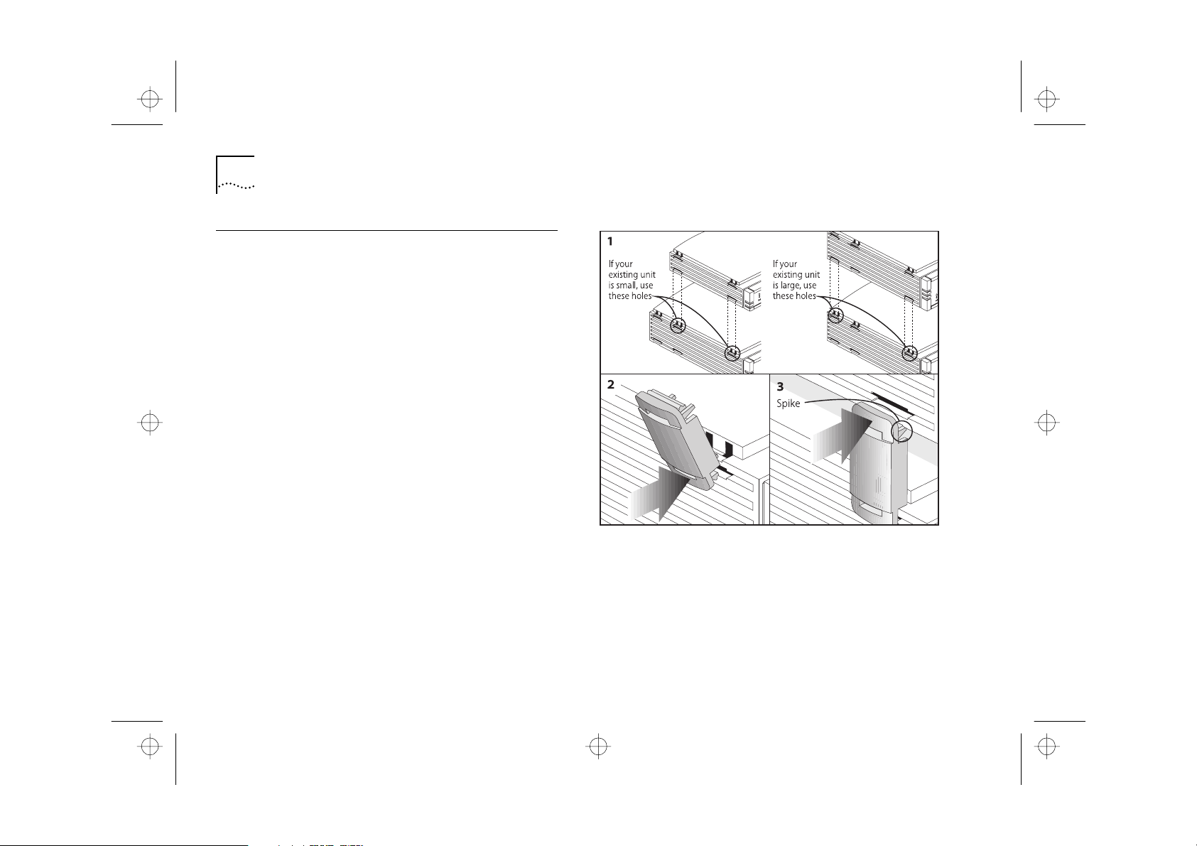
You can stack up to a maximum of four units.
Large units must be stacked below small units.
To stack your units, secure the clips on one side and
then on the other. Use the following method to
secure one side:
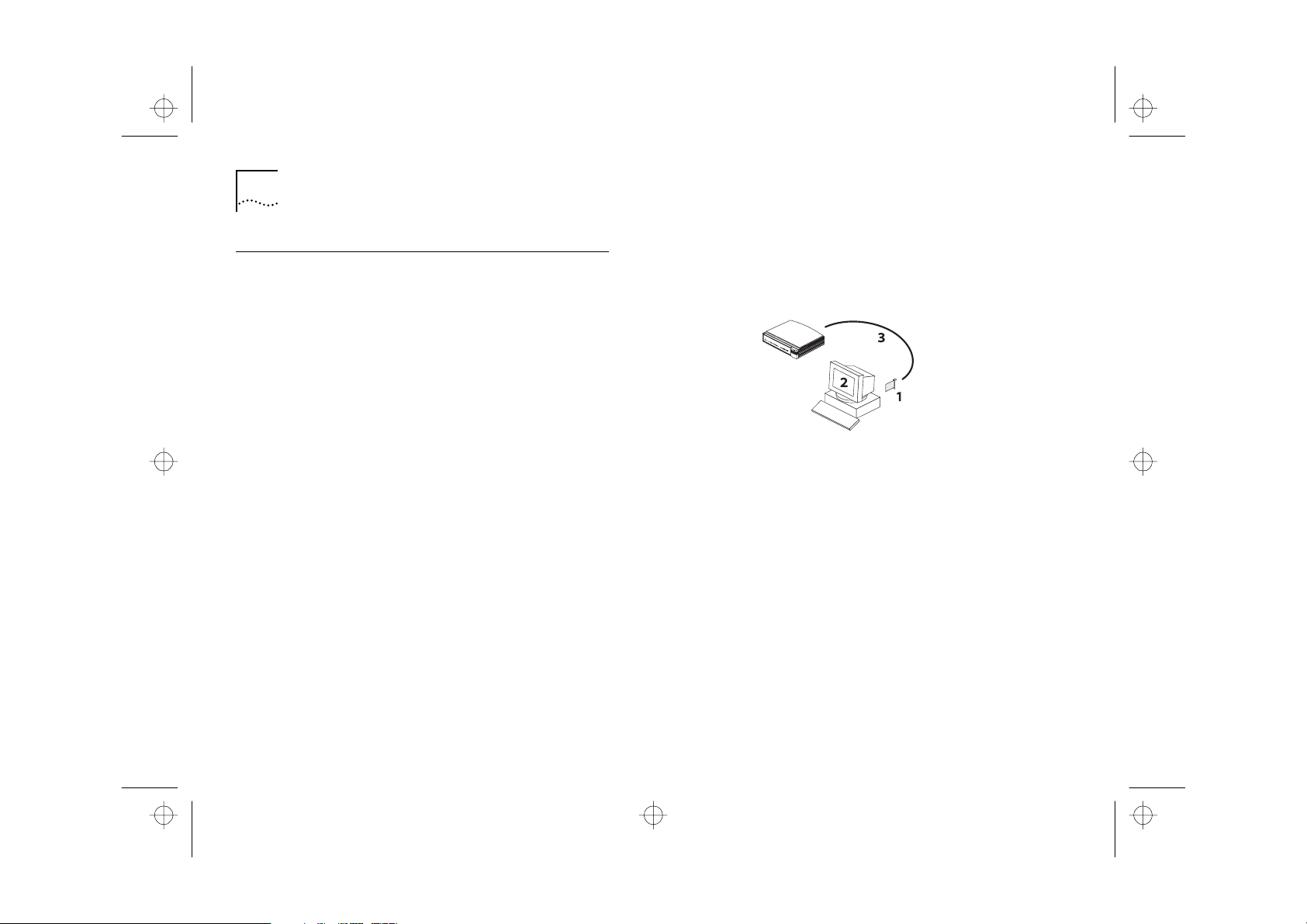
Place your new unit on a flat surface. Your clips fit in
the positions on the side of the unit, as shown in
Figure 2-3 (1).
Position a clip over one of these holes and push it in
until it clicks into place, as shown in Figure 2-3 (2).
Repeat this for the other clip position on the same
side.
Keeping the front of the units aligned, rest the
bottom of the existing u nit on the clips’ spikes, as
shown in Figure 2-3 (3). Push the clips firmly into the
existing u nit until they click into place.
Figure 2-3 Clipping Your Units Together
Repeat these steps to secure the other side.
To remove a clip, hold the units firmly with one
hand and hook the first finger of your other hand
around the back of the clip. Use reasonable force to
pull it off.
Page 23

16710.bk : CREYRNET.FRM Page 7 Tuesday, October 7, 1997 11:38 AM
Wall Mounting the Office Connect H ub
There are two slots on the underside of the
OfficeConnect hub which are used for wall
mounting. You can mount the hub with the LEDs
facing upwards or downwards, to suit your needs.
When wall mounting your hub, ensure that it is
within reach of the power outlet.
You need two suitable screws. Ensure that the wall
you are going to use is smooth, flat, dry and sturdy.
Make two screw holes which are 1 42 mm (5. 6 in)
apart. Use the arrows at the top of the Quick
Reference Guide to mark the position of the holes.
Fix the screws into the wall, leaving their heads 3 mm
(0.12 in) clear of the wall surface.
Remove any connections to the hub and locate it
over the screw heads. When in line, gently push the
hub on to the wall and move it downwards to
secure. When making connections, be careful not to
push the hub up and off the wall.
CAUTION:
mount stacked hubs.
Only wall mount single hubs, do not wall
Wall Mounting the Office Connect H ub
Connecting Workstations and Other
Equipment to Your Hub
WARNING:
Safety Information section carefully before you start.
ACHTUNG:
Abschnitt mit den wichtigen Sicherheitshinweisen
gelesen haben, bevor Sie das Gerät benutzen.
AVERTISSEMENT:
soigneusement la section de L’information de Sécurité
Importante avant que vous commenciez.
CAUTION:
Wait about 5 seconds between power cycles.
Connecting workstations and other equipment to
your hub is easy. Connect them using 10BASE-T
cables to any of the hub’s eight 10BASE-T RJ45 ports.
10BASE-T cables are very easy to use. To connect a
10BASE-T cable, simply slot the connector into the
relevant RJ45 port. When the connector is fully in, its
latch locks it in place. To disconnect the cable, push
the connector’s latch in a nd remove it.
Ensure you have read the Important
Versichern Sie sich, daß Sie den
Assurer que vous avez lu
Do not power the hub off and on quickly.
2-7
Page 24

C H A P T E R
R E A T I N G Y O U R N E T W O R K
16710.bk : CREYRNET.FRM Page 8 Tuesday, October 7, 1997 11:38 AM
2-8
The hub detects all port connections, so you can
start using your network immediately. When you
need more ports, simply add more Office Connect
hub s.
If you are using port 8 to connect a workstation,
ensure the MDI/MDIX switch is set to MDIX.
If you do not use the 10BASE-2 (Coax) port, you do
not need to terminate it with a terminator (end
piece) .
2: C
Conne cti ng Office Connect H ubs Together
You can increase the number of workstations that
can connect to your network by adding more
OfficeConnect hubs. You can use either 10BASE-T or
10BASE-2 (Coax) to do this:
■
With 10BASE-2 (Coax) you can connect up to 30
hubs on a single segment, leaving all of the RJ45
ports free.
■
With 10BASE-T you can connect up to four hubs in
series.
CAUTION:
together using both 10BASE-T and 10BASE-2 (Coax).
This causes a network loop.
Do not connect the same two hubs
Page 25
16710.bk : CREYRNET.FRM Page 9 Tuesday, October 7, 1997 11:38 AM
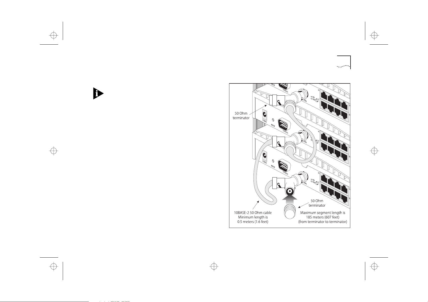
Connecting Hubs Using 10BASE-2 (Coax)
When using 10BASE-2 (Coax) cable, it is important
that both ends of the segment are properly
terminated with 50 Ohm terminators ( end pieces ) .
Only use 50 Ohm 10BASE-2 (Coax) cables and use a
‘Y’ piece for each hub. You can use ‘T’ pieces but ‘Y’
pieces provide adequate clearance of the other ports.
Connect a 10BASE-2 ‘Y’ piece to each of your hubs.
Daisy-chain each ‘Y’ piece with 10BASE-2 (Coax)
cable to form a single segment, as shown in
Figure 2-4 . Remember to terminate the two free ends
of the segment by fit ting t erminators (end pieces).
To disconnect a 10BASE-2 (Coax) cable, twist each
connector counter-clockwise to unlock it, and
remove it.
Conne cti ng Office Connect H ubs Together
2-9
Figure 2-4 Correct Hub Connections Using 10BASE-2 (Coax)
Page 26
H A P T E R
R E A T I N G Y O U R N E T W O R K
1
2
16710.bk : CREYRNET.FRM Page 10 Tuesday, October 7, 1997 11:38 AM
2-10 C
2: C
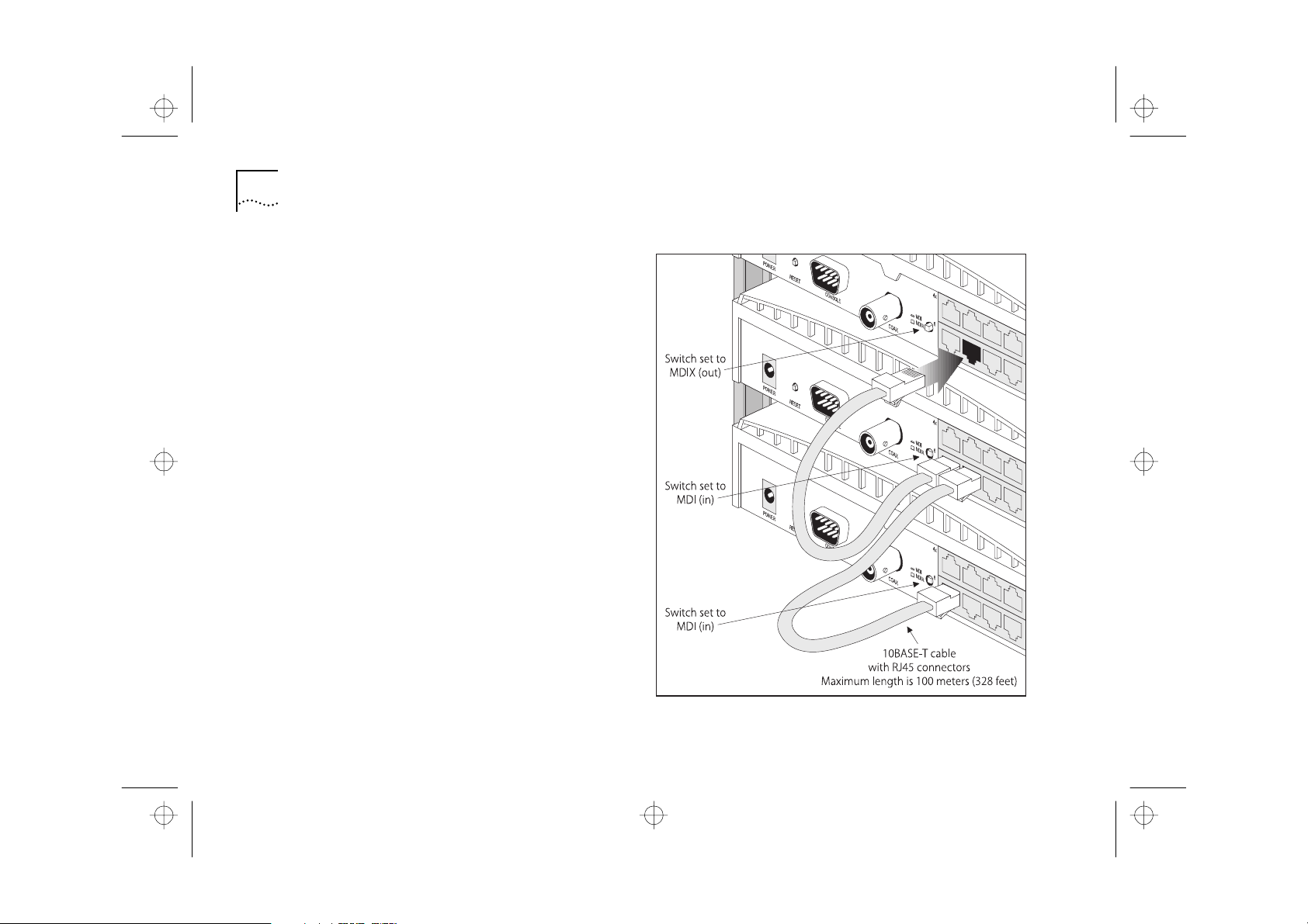
Connecting Hubs Using 10BASE-T
You can connect hubs together with 10BASE-T in a
number of ways, but for simplicity we recommend
the following method:
Starting from the bottom, connect port 8 of the
lower hub to port 7 of the hub immediately above.
Repeat for each hub, as shown in Figure 2-5 .
Set all MDI/MDIX switches to MDI (in) except for the
top hub (the one with port 8 not connected to
another hub). This unused port can be connected to
a workstation provided that the MDI/MDIX switch is
set to MDIX (out).
Figure 2-5 Correct Hub Connections Using 10BASE-T
Page 27

S
S
16710.bk : CREYRNET.FRM Page 11 Tuesday, October 7, 1997 11:38 AM
pot Checks 2-11
Checking Hub Connections
When you have connected your hubs, power them
on. The Port Status LEDs for the ports you have used
should be green for 10BASE-T, or off for 10BASE-2
(Coax). If they are not, check your connections .
If the 10BASE-2 (Coax) port is not used and is not
terminated, the LED should be yellow showing that it
has partitioned. This is correct operation.
pot Checks
At frequent intervals, visually check that:
■
The Alert LED is not lit — this is the best way to find
out if there are problems with your network
■
Case vents are not obstructed
■
Cabling is secure and not pulled taut
If you suspect there is a problem, refer to Chapter 6 .
Page 28

H A P T E R
R E A T I N G Y O U R N E T W O R
16710.bk : CREYRNET.FRM Page 12 Tuesday, October 7, 1997 11:38 AM
2-12 C
2: C
K
Page 29

A B O U T
E T W O R K
A N A G E M E N T
®
16710.bk : ABOUTMAN.FRM Page 1 Tuesday, October 7, 1997 11:38 AM
3
Network management is not required to get your hub
working, it simply allows you to change the way it
works and to monitor what is happening to your
network. Each OfficeConnect® Hub 8/TPM is a separate
manageable entity, that means you manage each
OfficeConnect Hub 8/TPM individually. This chapter lists
the management tasks you can perform, and describes
the ways you can connect your management station to
your hub. This guide uses
refer to the piece of equipment you are using to
manage the hub.
Transcend Quick Configuration Manager, referred to as
‘Quick Config Manager’
your hub and provides an easy-to-use graphical
management system, through the hub’s console port.
Quick Config Manager uses a familiar Windows
interface with point and click operation. To use it
effectively, you need to be familiar with Microsoft
Windows. For information on Microsoft Windows, refer
to the Microsoft Windows User’s Guide.
You can also manage your hub using a VT100 terminal
or any Telnet facility that emulates a VT100 terminal.
VT100 uses a text-based user interface.
N
‘Management Station’
in this guide, is supplied with
to
M
3Com Network Management
Quick Config Manager provides a subset of the
functionality that is present in other 3Com
management applications, for example the
IP/IPX-based Transcend® Enterprise Manager for
Windows (version 4.x and above).
Whether your network is large or small, its ongoing
performance, growth and security are only as good
as its management system.
Using intelligent 3Com software distributed
throughout the network, 3Com’s Transcend
management applications support all of today’s
platforms and manage a wide variety of 3Com
products. This gives you total control over your entire
3Com network from a single management station.
For further information about which Transcend
management application can benefit your growing
network, call your local sales office, see “3Com
provides easy access to technical support
Page 30

C H A P T E R
B O U T N E T W O R K M A N A G E M E N T
IP -
16710.bk : ABOUTMAN.FRM Page 2 Tuesday, October 7, 1997 11:38 AM
3-2
3: A
information through a variety of services. This
appendix describes these services.” on page C-1 .
Why Manage Your Hub?
With management, you can change and view the
way your hub and network operates:
■
Configure IP information for the hub so that an
based network management station can
communicate with it.
■
Restart the hub to refresh its statistics and use any
new configurations.
■
Initialize the hub to return it to its factory settings
(IP and console port i nformation is re t ained ).
■
Display a graphical representation of the hub to
quickly view the status of each port.
■
Display general hub information.
■
Configure the Alert LED to light for a number of
conditions, and show what conditions have triggered
the Alert LED to come on.
■
Graphically display network information for each port
and the hub.
■
Enable and disable ports.
Page 31

16710.bk : ABOUTMAN.FRM Page 3 Tuesday, October 7, 1997 11:38 AM
■
Configure security for the hub, including setting up
new users and specifying what equipment is
allowed to communicate through the hub.
■
Set up resilience; specify a backup connection that
takes over should a main connection fail.
■
Configure the hub to send messages over the
network or a modem link, to an IP/IPX-based
management application ( for example, Transcend
Enterprise Manager) , reporting the state of the hub
and the network.
■
Use the hub to monitor other devices on your
network and report any deviation from their normal
operation t o an IP/IPX-based management
application.
■
Poll a remote device to see if it is operational.
■
View any faults that have occurred with the hub.
■
Download any future software upgrades to the hub.
Connecting to the Hub and Managing
Connecting to the Hub and Managing
Managing your hub is easy. There are many ways you
can connect your management station to your hub,
as shown in Figure 3-1 .
You can manage the hub:
■
Through the console port
Using Quick Config Manager
■
Using a VT100 Terminal Emulator
■
Using a VT100 Terminal
■
■
Over the network
Using an IP/IPX-based N etwork M anager
■
Using a VT100 Terminal Emulator through Telnet
■
For information on using modems as part of your
management connection, see “Remote
Management Service” on page 3-7 .
3-3
Page 32

C H A P T E R
B O U T N E T W O R K M A N A G E M E N T
Co
t hr
r em
t hr
16710.bk : ABOUTMAN.FRM Page 4 Tuesday, October 7, 1997 11:38 AM
3-4
3: A
Managing Through the Console Port
This section describes how to connect and set up
equipment to communicate with the hub through
the console port (called
By default, the hub automatically configures its baud
rate. T he maximum rate the autoconfiguration
function detects is 1 9 2 00 baud.
You need to use a null modem cable for connection
to the hub’s console port. This is available from your
supplier. The null modem cable must:
■
Have a 9 pin female ‘D’ connector for connection to
your hub, and the appropriate connector for
connection to your management station.
■
Not exceed 15 meters (50 feet).
There are a variety of null modem cables that you
can use. For an example of one of these, s ee
“Cabling” on page A-2 .
out-of-band
management).
Figure 3-1 Different Management C on nections To The Hub
nnection to the console port may be direct or
ough modems, giving the option of local or
ote management. For information on managing
ough modems, se e “Remote Management
Service” on page 3-7 .
Page 33

C
C
C
16710.bk : ABOUTMAN.FRM Page 5 Tuesday, October 7, 1997 11:38 AM
Using Quick Config Manager
onnect one end of the null modem cable to the
console port on the hub, and the other to the serial
(RS232) port on your management station.
Quick Config Manager uses SLIP to manage your
hub. When you have made your connection and
installed Quick Config Manager, you are ready to
manage your hub.
Refer to Chapter 4 for information on installing and
using Quick Config Manager.
Using a VT100 Terminal Emulator
onnect one end of the null modem cable to the
console port on the hub, and the other to the serial
(RS232) port on your management station. You need
to set the character size (8), stop bit (1) and parity
(none) settings of your management station to work
with the hub.
Press [Return][Return] to start the communication.
The management station you are using needs to run
suitable terminal emulation software. Many VT100
terminal emulation packages are available.
Connecting to the Hub and Managing
Microsoft Windows has a terminal emulation
program called ‘HyperTerminal’ (for Windows 95) or
‘Terminal’ (for other Windows versions).
Refer to the documentation that accompanies your
particular terminal emulation package for details, or
consult your supplier if you need further advice.
Refer to Chapter 5 for information on performing
additional management using the VT100
management interface.
3-5
Using a VT100 Terminal
onnect one end of the null modem cable to the
console port on the hub, and the other to the serial
(RS232) port on your VT100 terminal. You need to set
the character size (8), stop bit (1) and parity (none)
settings of your VT100 terminal to work with the hub.
Press [Return][Return] to start the communication.
Refer to Chapter 5 for information on performing
additional management using the VT100
management interface.
Page 34

C H A P T E R
B O U T N E T W O R K M A N A G E M E N T
u
1
2
16710.bk : ABOUTMAN.FRM Page 6 Tuesday, October 7, 1997 11:38 AM
3-6
3: A
Managing Over the Network
This section describes how to set up equipment to
allow you to communicate with the hub over the
network (called
Before you can manage your hub over the network
sing IP , you must connect to its console port locally
and use Quick Config Manager to enter IP
information for the hub:
Connect one end of a null modem cable to the
console port on the hub, and the other to the serial
(RS232) port on your management station.
Install Quick Config Manager and use it to configure
the necessary IP information for the hub.
Refer to Chapter 4 for information on installing and
using Quick Config Manager.
If using IPX, you do not need to enter IPX information
for the hub.
in-band
management).
Using an IP/IPX-based Network
Management Application
3Com’s Transcend network management applications
enable you to get the best out of your hub. Any
IP/IPX-based network management application can
manage the hub.
The use of IP/IPX-based network management
applications is not described in this manual. Refer to
the user documentation that accompanies your
application, for more information.
Using a VT100 Terminal Emulator
(over Telnet)
Any VT100 terminal emulator that uses Telnet should
be able to communicate with the hub over the
network. Up to three active management sessions
can access the hub concurrently. If a connection to a
session is not closed, but is lost inadvertently, the
connection is closed by the hub after between 2
and 3 minutes of inactivity.
Refer to the documentation that accompanies your
particular terminal emulation package for details, or
consult your supplier if you need further advice.
Page 35

Th
16710.bk : ABOUTMAN.FRM Page 7 Tuesday, October 7, 1997 11:38 AM
Refer to Chapter 5 for information on performing
additional management using the VT100
management interface.
Remote Management Service
e OfficeConnect hub has a special modem dial-out
feature which can be set up by your supplier to
inform them when your hub or network is operating
incorrectly. This allows your supplier to know
immediately when certain problems occur, so they
can act on it, leaving you to carry on with your work.
Contact your supplier to find out if they are offering a
support service based on this feature.
Remote Management Service
3-7
Page 36

C H A P T E R
B O U T N E T W O R K M A N A G E M E N
16710.bk : ABOUTMAN.FRM Page 8 Tuesday, October 7, 1997 11:38 AM
3-8
3: A
T
Page 37

A N A G I N G
O U R
U B U S I N G
U I C K
O N F I G
A N A G E R
”
16710.bk : MANAGING.FRM Page 1 Tuesday, October 7, 1997 11:38 AM
M
Y
4
Q
This chapter describes how to install and use Quick
Config Manager. For an overview of what you can
do when managing the hub, see Chapter 3 .
The sections in this chapter are in the order you
would normally p erform them when managing the
hub for the first time. If you are new to network
management, read through this chapter to learn
about the different management you can perform.
Quick Config Manager has a comprehensive help
system that has the same useful information as this
chapter.
Before you can manage with Quick Config Manager,
you must make a connection to the hub’s console
port, see Chapter 3 .
In the descriptions of the options given in this
chapter, the default values are underlined.
C
H
M
Installing Quick Config Manager
Installation Requirements
Quick Config Manager requires an IBM compatible
PC with at least a 486/33 processor. Your system
must also include:
■
Microsoft Windows ® 3.1
or Windows for Workgroups 3.11
or Windows 95.
■
MS-DOS 5.0 or later (not needed for Windows ‘95) .
■
Minimum of 4MB available hard disk space.
■
Minimum of 8MB RAM. All RAM above the first
megabyte must be configured as extended memory.
■
3.5
disk drive.
■
VGA or SVGA color monitor.
■
Mouse.
■
Serial port capable of 9600 baud, no Parity, 8bit
Data, 1 StopBit.
Page 38

C H A P T E R
A N A G I N G Y O U R H U B U S I N G Q U I C K C O N F I G M A N A G E R
1
I
2
3
4
”
16710.bk : MANAGING.FRM Page 2 Tuesday, October 7, 1997 11:38 AM
4-2
4: M
Installation Procedure
Quick Config Manager can be installed on its own or
on to a workstation that already has other
Transcend® management applications installed on it.
CAUTION:
the same directory as any other Transcend
management applications. The default directory into
which Quick Config Manager is installed is
C:\QUICKMGR. This can be changed during the
installation if required.
The installation program is a standard Windows
based installation. To install Quick Config Manager:
Start Windows.
f you already have an existing Transcend
management application running, ensure that it is
closed down.
Insert the Quick Config Manager disk into your disk
drive.
In the Program Manager window, select the
command from the
Do not install Quick Config Manager in
File
menu.
Run
Command Line
In the
drive
(where
and click on OK.
The installation program starts and checks your
system configuration; enter any information that’s
requested. The installation program reports when it
has completed the installation.
When the Quick Config Manager installation is
complete, it has its own program group called
Transcend. If other Transcend management
applications are present, the existing Transcend
program group now includes Quick Config Manager.
box, type
is the letter of your 3.5
drive
Running Quick Config Manager
Whenever you want to start the Quick Config
Manager application, double-click on the Quick
Configuration Manager icon.
CAUTION:
parallel with any other Transcend management
application.
Before you can manage your hub, you must make a
connection to the hub, see Chapter 3 .
Do not run Quick Config Manager in
:\SETUP
disk drive)
Page 39

1
2
.
16710.bk : MANAGING.FRM Page 3 Tuesday, October 7, 1997 11:38 AM
Configuring Multiple Hubs 4-3
If you are going to manage over a serial link from
your management station, Quick Config Manager
uses COM1 as the default serial port. You can
change this by editing the following line under the
[slip] subsection of the QUICKMGR.INI file:
Serial Attri b=CO M1:9 60 0,n, 8,1
Editing it to
changes the default serial port to COM2.
Seria lAtt rib= COM2: 96 00,n ,8,1
Configuring Multiple Hubs
There is a special feature which allows you to
connect your management station to a new
OfficeConnect® Hub 8/TP M without needing to
close and reopen Quick Config Manager. This is
particularly useful if you have many OfficeConnect
hubs that need configuring or monitoring.
This feature only works if all the hubs you are going
to connect to have the same baud rate (or are set to
Auto Config) as the management station.
To d o this:
Make your serial connection to the new hub.
From the
Quick Config Manager closes any windows that are
open in preparation for the new management
session.
File
menu, select
Reset View
Quick Config Manager Window Map
Figure 4-1 (over the page) shows how all of the Quick
Config Manager windows are accessed. This diagram
also appears on the Quick Reference Guide. The
number at the top right-hand side of each window
refers to the page that describes the window.
Page 40

C H A P T E R
A N A G I N G Y O U R H U B U S I N G Q U I C K C O N F I G M A N A G E R
16710.bk : MANAGING.FRM Page 4 Tuesday, October 7, 1997 11:38 AM
4-4
4: M
Figure 4-1 Quick Config Manager Window Map
Page 41

16710.bk : MANAGING.FRM Page 5 Tuesday, October 7, 1997 11:38 AM
Quick Config Manager Window Map
4-5
Page 42

C H A P T E R
A N A G I N G Y O U R H U B U S I N G Q U I C K C O N F I G M A N A G E R
T he d
1
2
.
3
4
OK .
C
16710.bk : MANAGING.FRM Page 6 Tuesday, October 7, 1997 11:38 AM
4-6
4: M
Accessing the Hub
The OfficeConnect Hub 8/TP M uses
strings
as a security measure, to check management
access to the hub. T he community string you use
must match one of the community strings
configured for the hub. Quick Config Manager
remembers the last community string used.
efault community strings are:
security
■
■
— allows you to view and configure the
hub’s information
public
— allows you to view the hub’s information
To enter the community string:
Double-click on the Quick Config Manager icon to
start the application.
From the
Quick Config Manager displays the
Community/Polling dialog box, as shown in
Figure 4-2 .
Enter the community string in the box.
Configure
menu, select
community
Figure 4-2 Community/Polling Dialog Box
Community/Polling
hanges made to this dialog box will only take effect
for new windows. An y graphs or zoom view windows
that are already open wi ll continue to use the old
values. Close these windows and reopen them to use
the new values.
Click on
Page 43

15
d
co
T
16710.bk : MANAGING.FRM Page 7 Tuesday, October 7, 1997 11:38 AM
You can also use the Community/Polling screen to:
■
Automatically di splay a graphical representation of
the hub every time you start Q uick Config Manager.
■
Define how regularly the graphical representation of
the hub is updated.
■
Define how regularly any displayed graphs are
updated.
Bitmap
The time in minutes between consecutive updates of
the graphical representation of the hub. If Off is
selected, the bitmap is not updated at all (you can
select
any new states).
Graph(s)
The time in seconds between consecutive updates of
any graphs that are displayed.
Invoke zoom view on start-up
want the graphical representation of the hub to be
Through VT100 management you can configure new
users for the hub (with different community strings) ,
see “Configuring Users” on page 5-17 .
Off / 15 / 30 / 45 / 60
Update Zoom
isplayed every time you start Q uick Config Manager.
from the
/ 30 / 4 5 / 60
File
menu to display
Check this box if you
Giving the Hub an IP Address
Giving the Hub an IP Address
You can configure the hub with an IP address and
other useful information, e nabl ing i t to
mmunicate over (become part of) an IP network .
The hub does not need an IP address to make your
Quick Config Manager work with it.
You need to give your hub an IP address if you want
to use an IP-based network manager, for example
Transcend Enterprise Manager, to manage it over the
network.
CAUTION:
see “IP Addresses” on page B-1 .
he IP Setup d ialog box is used to set up IP
information and change the SLIP address for the hub.
The IP Setup dialog box has a useful Easy Setup
option which takes you through the IP configuration
process. The information that you enter during the
Easy Setup process is the same as, and is entered
into, the IP Setup dialog box.
If you have no previous knowledge of IP,
4-7
Page 44

C H A P T E R
A N A G I N G Y O U R H U B U S I N G Q U I C K C O N F I G M A N A G E R
1
d
.
No
.
16710.bk : MANAGING.FRM Page 8 Tuesday, October 7, 1997 11:38 AM
4-8
4: M
To display the IP Setup dialog box and view or
configure the hub’s address settings:
From the
Configure
menu, select
IP Setup
Quick Config Manager d isplays either the IP Setup
ialog box or the Easy Setup Option, as shown in
Figure 4-3 , depending on what IP information is
currently configured for the hub:
■
If an IP address has been configured for the hub,
and it is not 0.0.0.0, the IP Setup dialog box is
displayed. If you have previously configured
address information for the hub but want to go
through the Easy Set-Up option again, you can
start it by clicking on the
■
If no previous IP information has been
Easy Set-Up
configured for the hub or the IP address is
configured as 0.0.0.0, and the Enable IP box is
checked, the Easy Setup option is started. If you
want to enter information directly into the IP
Setup screen or abort the Easy Setup process,
Abort
select
The Easy Setup option asks you if you want to
manually configure the hub for IP. If you have a
BOOTP server (that automatically allocates IP
addresses) select
, otherwise select
...
button.
Ye s
Figure 4-3 IP Setup D ialog Box And Easy Setup Option
Page 45

2
OK
3
—
—
s
—
16710.bk : MANAGING.FRM Page 9 Tuesday, October 7, 1997 11:38 AM
Enter the relevant information into the IP Setup
diolog box or Easy Setup screens and click on
exit the screens.
Reset the hub for any changes to take effect, see
“Resetting the Hub” on page 4-11 .
After resetting the hub, you may need to select
Reset View
from the
File
menu to restart
communication using the new information.
CAUTION:
Always make a note of any changes you
make to the settings on this screen. There is an area
at the front of this User Guide for doing this, called
“Your Hub Addresses” .
Device Configuration
Device Name
■
Show s the following:
Provides a box for you to type a
name for the hub. Use a descriptive name, for
example ‘ Finance’ .
Emergency Contact
■
Provides a box for you to type
the name and/or telephone number of your
network administrator (possibly yourself) who
should be contacted in an emergency.
to
Giving the Hub an IP Address
Support Contract
■
— Provides a box for you to type
the ID number of any technical support contract you
may have.
The default entries for these three fields is ‘3Com’.
These defaults are just place holders and should be
changed for your information as soon as possible.
These three fields u se the same information as
ysContact and sysName i n the MIB II panel , so if you
change them, the fields in the MIB II panel change as
well. For information on the MIB II panel, see
“Displaying Information About the Hub” on
page 4-13 .
Network Configuration
IP Address
■
Provides a box for you to type the IP
Show s the following:
address of the hub .
CAUTION:
To ensure that Quick Config Manager can
always communicate with the hub, the IP subnet
192.168.101.x is permanently assigned to the SLIP
port in addition to the user configurable SLIP
address. Do not use this subnet for your Ethernet
(network).
4-9
Page 46

H A P T E R
A N A G I N G Y O U R H U B U S I N G Q U I C K C O N F I G M A N A G E
—
—
—
16710.bk : MANAGING.FRM Page 10 Tuesday, October 7, 1997 11:38 AM
4-10 C
Subnet Mask
■
4: M
Provides a box for you to type the
subnet mask for the I P address.
Enable IP
■
— If disabled, the IP fields for this dialog
box are blanked and grayed-out. If enabled, the IP
fields are enabled, allowing you to enter your IP
information. If you are not going to manage the hub
over the network, disable IP.
Out of Band Configuration
Serial Line IP Address
■
Show s the following:
SLIP a llows IP to run over the
console port instead of the network. SLIP allows you
to use out-of-band management, either locally or
remotely through a modem. SLIP operates with any
valid IP address. The default is 192.168.101.1 which is
the address Quick Config Manager uses.
SubNet Mask
■
Enter the SLIP s ubnet mask. For a
class C address, 255.255.255.0 (the default ) is suitab le.
If you are using SLIP and have c hang ed any of the
console port settings using VT100, ensure that Flow
Control is not set to XON/XOFF, see “Connecting a
Modem to the Console Port” on page 5-13 .
R
Router IP Address
Enter the IP address of the router
(if you have one) which is used by the hub to
communicate with other networks.
Manager IP Address
Enter the IP address of a
management station that has an IP-based network
management application running on it. You can
configure the hub to send messages, called
this management station .
Quick Config Manager does not have a facility to
receive traps because it is a configuration tool, not a
management tool.
traps
, to
If you require more information about SLIP, read the
Internet Activities Board document RFC 155.
Page 47

Re
1
. Q
2
OK .
1
.
2
OK .
16710.bk : MANAGING.FRM Page 11 Tuesday, October 7, 1997 11:38 AM
Resetting the Hub 4-11
Resetting the Hub
Resetting the hub simulates switching the hub off
and on. You may want to reset the hub if you want
to:
■
Apply any changes made to the hub’s IP
configuration.
■
sets the hub’s statistics counters.
CAUTION:
the data being transmitted over the network to be
lost.
To r e s e t the hub:
From the
uick Config Manager asks you to confirm the reset .
In the confirmation dialog box, click on
The hub takes about 20 seconds to reset itself. Yo u
may need to select
re-establish communication with the hub.
Performing a reset may cause some of
Configure
menu, select
Reset View
from the
Reset
File
menu to
Initializing the Hub
Initializing the hub causes it to return to its factory
default settings. You may want to do this if the hub
has been previously used in a different part of your
network, and its settings are incorrect for its new
environment.
CAUTION:
configuration information such as security, resilient
links and passwords. However, the IP address, subnet
mask, default router, SLIP and console port
information is r etained to ensure you can continue
management communication with the hub over the
network.
To initialize the hub:
From the
Quick Config Manager asks you to confirm the
initialization .
In the confirmation dialog box, click on
The hub takes about 20 seconds to initialize itself.
You m ay need to select
to re-establish communication with the hub.
Initializing the hub removes all
Configure
menu, select
Reset View
Initialize
from the
File
menu
Page 48

H A P T E R
A N A G I N G Y O U R H U B U S I N G Q U I C K C O N F I G M A N A G E R
.
h
T
Y
c
16710.bk : MANAGING.FRM Page 12 Tuesday, October 7, 1997 11:38 AM
4-12 C
4: M
Viewing the Hub
Quick Config Manager can display a graphical
representation of the hub you are managing, with:
■
The ports color coded to show their condition
■
The Alert LED reflecting its physical state
To display the hub:
■
From the
Quick Config Manager displays a zoom view of the
ub, as shown in Figure 4-4 . If the zoom view is
already open, it is selected.
Figure 4-4 Zoom View Of The Hub
View
menu, select
Zoom In
he port color coding shows th ese c onditions:
Green
■
— Port enabled and capable of receiving and
transmitting traffic
Red
■
— Port enabled and partitioned, or port
enabled but the connection is los t
Blue
■
— Port disabled by management
In the Community/Polling dialog box, you can
specify whether the zoom view is invoked on starting
Quick Config Manager, and how often the zoom view
is polled (updated). If you want to update the zoom
view immediately, without waiting for a poll, select
Update Zoom from the File menu.
Double-clicking on the Zoom View
ou can configure i nformation for t he h ub by
double-clicking on the zoom view:
■
If you double-click on a port, the Port dialog box is
displayed. This is used to c onfigure information for a
port, see “Configuring a Port” on page 4-25 .
■
If you double-click on anything other than a port, the
General Info dialog box is displayed. This is used to
onfigure information for the h ub, see “Displaying
Information About the Hub” on page 4-13 .
Page 49

1
2
16710.bk : MANAGING.FRM Page 13 Tuesday, October 7, 1997 11:38 AM
Displaying Information About the Hub 4-13
Displaying Information About the Hub
Quick Config Manager enables you to display
detailed information about the hub. This information
is stored within the hub in a list, called a
(Management Information Base). The MIB defines
what information can be obtained from the hub by
an SNMP network management station.
To display this information:
Do one of the following:
■
Double-click on the graphical representation of
the hub (but not on a port).
■
From the
Configure
menu, select
MIB
General Info
...
In the General Info dialog box, select the
MIB II
category.
Quick Config Manager displays the MIB II panel , as
shown in Figure 4-5 .
Figure 4-5 MIB II Panel
Page 50

H A P T E R
A N A G I N G Y O U R H U B U S I N G Q U I C K C O N F I G M A N A G E R
s
d
16710.bk : MANAGING.FRM Page 14 Tuesday, October 7, 1997 11:38 AM
4-14 C
sysDescr
the hub’s Management Agent software.
sysObjectId
the hub’s Management Agent software.
sysUpTime
the last reset.
sysContact
of the person who can be contacted in the event of a
problem with the hub.
sysName
of the hub.
ysContact and s ysName u se the same information
as the Device C on figuration fields in the IP Setup
ialog box , so if you change them, the fields in the
IP Setup dialog box change as well.
For information on the IP Setup d ialog box, see
“Giving the Hub an IP Address” on page 4-7 .
4: M
Shows the system description supplied by
Shows the SNMP object identifier for
Shows the time that has elapsed since
Provides a box for you to type the name
Provides a box for you to type the name
sysLocation
location of the hub.
sysServices
supports.
Refresh
Provides a box for you to type the
Shows the services that the hub
Refreshes the information in the panel .
Page 51

1
2
16710.bk : MANAGING.FRM Page 15 Tuesday, October 7, 1997 11:38 AM
Setting Up the Alert LED 4-15
Poll Failures
Setting Up the Alert LED
The Alert LED can warn you of potential problems
with your network. Quick Config Manager allows
you to:
■
Test the Alert LED.
■
Configure the conditions that cause the Alert LED to
light.
■
View what conditions have caused the Alert LED to
light.
■
monitor a device, it periodically polls it for
information. If the device fails to respond, the failure
is seen by the hub.
Network Errors
■
communication, or there is a high amount of errors
with the communication, it could be due to too
many devices on your network or an incorrectly
configure device.
By default, the Alert LED is configured to light if a
10BASE-T port is partitioned or if there is high
network utilization (over 80%).
— If your hub has been configured to
— If the network has high volumes of
You can configure the Alert LED to light for:
Incorrect configurations
■
— If there is a network loop
due to an incorrect configuration in your network, a
port partitions. The coaxial port automatically
partitions if it is not used.
Security Violations
■
— If an unsuccessful login attempt
occurs, or a device that is not known to your hub
tries to communicate with it, a violation occurs. This
may be due to someone trying to gain unauthorized
access to your network.
To configure the Alert LED:
Do one of the following:
Double-click on the graphical representation of
■
the hub (but not on a port).
■
From the
Configure
menu, select
In the General Info dialog box, choose the
General Info
Alerts
...
category.
Quick Config Manager displays the Alerts panel , as
shown in Figure 4-6 .
Page 52

H A P T E R
A N A G I N G Y O U R H U B U S I N G Q U I C K C O N F I G M A N A G E R
3
4
OK
OK
16710.bk : MANAGING.FRM Page 16 Tuesday, October 7, 1997 11:38 AM
4-16 C
Figure 4-6 Alerts Panel
Configure the conditions for the Alert LED.
4: M
If any Alert conditions are active, the conditions are
displayed in red. The other conditions are displayed
in green. If the active conditions are enabled, the
Alert LED will be lit.
In the Alerts panel :
Alert LED Test
Allows you to test the Alert LED. If you select Enable
and click on
true alert condition of the hub.
When you have finished your test, remember to
disable to Alert LED Test. To do this, select Disable and
click on OK. The Alert LED now reflects the current
Alert condition of the hub.
UTP Port Partition
Allows you to specify whether the Alert LED lights if
a UTP port becomes partitioned, which happens if a
network loop occurs.
Enabled / Disabled
, the Alert LED lights regardless of the
Enabled / Disabled
Click on
when the Aler t LED setup is complete.
If this condition is resolved after causing the Alert
LED to light, the LED goes off (it stays lit if other
conditions also caused it to light).
Page 53

a
16710.bk : MANAGING.FRM Page 17 Tuesday, October 7, 1997 11:38 AM
Setting Up the Alert LED 4-17
Coax Port Partition
Allows you to specify whether the Alert LED lights if
the coaxial port becomes partitioned.
If this condition is resolved after causing the Alert
LED to light, the LED goes off (it stays lit if other
conditions also caused it to light).
Login Violation
Allows you to specify whether the Alert LED lights if
a login violation occurs, which happens if a user
attempts to log on to your hub using the VT100
screens with an invalid username/password
combination three consecutive times.
If this condition caused the Alert LED to light, the
LED goes off after you have acknowledged the alert
by pressing the associated
lit if other conditions also caused it to light).
Port Security Violation
Allows you to specify whether the Alert LED lights if
a port security violation occurs, which happens if an
unauthorized device attempts to communicate
through your hub.
Enabled / Disabled
Enabled / Disabled
Ack
button (the LED stays
Enabled / Disabled
If this condition caused the Alert LED to light, the
LED goes off after you have acknowledged the alert
by pressing the associated
lit if other conditions also caused it to light).
Authentication Failure
Allows you to specify whether the Alert LED lights if
an authentication failure occurs, which happens if a
user attempts to access information on your hub
using an invalid community string.
If this condition caused the Alert LED to light, the
LED goes off after you have acknowledged the alert
by pressing the associated
lit if other conditions also caused it to light).
WorkGroup Monitor Failure
Allows you to specify whether the Alert LED lights if
workgroup monitor f ailure occurs, which happens if
a remote device fails to respond to a workgroup
monitor p oll from your hub.
If this condition caused the Alert LED to light, the
LED goes off after you have acknowledged the alert
by pressing the associated
lit if other conditions also caused it to light).
Ack
button (the LED stays
Enabled / Disabled
Ack
button (the LED stays
Enabled / Disabled
Ack
button (the LED stays
Page 54

H A P T E R
A N A G I N G Y O U R H U B U S I N G Q U I C K C O N F I G M A N A G E R
16710.bk : MANAGING.FRM Page 18 Tuesday, October 7, 1997 11:38 AM
4-18 C
Network Utilization
4: M
High / Med / Low / Disabled
Allows you to specify whether the Alert LED lights if
a certain level of network utilization is exceeded for
five seconds. The levels are:
High
■
■
■
— 80% network utilization
Med
— 50% network utilization
Low
— 12% network utilization
If this condition is resolved after causing the Alert
LED to light, the LED goes off (it stays lit if other
conditions also caused it to light).
Following a period of excessive network activity, the
Alert LED stays lit for a short period of time.
Network Error Rate
High / Med / Low / Disabled
Allows you to specify whether the Alert LED lights if
a certain level of network errors is exceeded for
approximately one minute. The levels are:
High
■
■
■
— 100 errors per 10000 frames
Med
— 10 errors per 10000 frames
Low
— 1 error per 10000 frame s
Monitoring
You can quickly and easily monitor your network by
viewing various types of network information:
■
Activity and errors
■
Frame types
■
Network traffic
■
Network errors
The information is displayed as a graph or pie chart,
and can be helpful for spotting and isolating any
potential network problems you may have.
To view general information for the hub, see
“Displaying Information About the Hub” on
page 4-13 .
If this condition is resolved after causing the Alert
LED to light, the LED goes off (it stays lit if other
conditions also caused it to light).
Page 55

1
2
3
4
OK .
.
16710.bk : MANAGING.FRM Page 19 Tuesday, October 7, 1997 11:38 AM
Monitoring 4-19
Monitoring Activity and Errors Statistics
Quick Config Manager allows you to display the total
network activity and errors seen by a port or the hub
(all ports) in any one time period.
To display the Activity/Errors graph for a port:
Double-click on the port for which you want to
display the Activity/Errors graph.
In the Port dialog box, choose the
In the Repeater Port Info panel, select the
check box.
Click on
To display the Activity/Errors graph for the hub:
■
From the
Quick Config Manager displays the Activity/Errors
graph, as shown in Figure 4-7 .
View
menu, select
Info
category.
Activity/Errors
Activity
Figure 4-7 Activity/Errors Graph
Page 56

H A P T E R
A N A G I N G Y O U R H U B U S I N G Q U I C K C O N F I G M A N A G E R
A h
16710.bk : MANAGING.FRM Page 20 Tuesday, October 7, 1997 11:38 AM
4-20 C
Total Errors
have occurred per poll, it should be a small
percentage of the readable frames figure.
Runts
octet counts less than the minimum legal size
(512 b its), which were not involved in a collision on
the segment being monitored . Runt frames are the
result of collisions on other segments and are
propagated around the network; this is a normal part
of Ethernet operation. An excessive number of runts
or collisions is an indication of congestion. You may
need to consider segmenting your network
(separating the busiest parts).
Readable
are of valid length and have not suffered a collision
or FCS error. Look for unusual increases in traffic rate;
this can indicate a potential problem.
Broadcast
which are addressed to all devices. The number of
broadcast frames is normally a small percentage of
the value seen for unicast (single address) frames.
network performance.
4: M
Shows the total number of errors that
Shows the number of frames received with
Shows the number of frames received that
Shows the number of frames received
igh level of broadcast frames can adversely affect
Collisions
transmission collision was detected. Collisions are a
normal part of Ethernet operation and occur if two or
more devices attempt to transmit at the same time.
A sudden sustained increase in the number of
collisions can indicate a problem with a device,
particularly if it is not accompanied by a general
increase in traffic. On coaxial segments an increase
in collisions can also indicate faulty cabling.
The values shown in the Activity/Errors graph are
per poll period, not per second. To change the poll
period, see “Accessing the Hub” on page 4-6 .
Shows the number of frames for which a
Page 57

1
2
3
4
OK .
.
16710.bk : MANAGING.FRM Page 21 Tuesday, October 7, 1997 11:38 AM
Monitoring 4-21
Frame Types Statistics
Quick Config Manager allows you to display the total
network frame types seen by a port or the hub (all
ports) in any one time period. Any frames producing
errors are not included, these are shown in the
Activity/Errors graph, see “Monitoring Activity and
Errors Statistics” on page 4-19 .
To display the Frame Types pie chart for a port:
Double-click on the port for which you want to
display the Frame Types pie chart.
In the Port dialog box, choose the
In the Repeater Port Info panel, select the
check box.
Click on
To display the Frame Types pie chart for the hub:
■
From the
Quick Config Manager displays the Frame Types pie
chart, as shown in Figure 4-8 .
View
menu, select
Info
Frame Types
category.
Frames
Figure 4-8 Frame Types Pie Chart
Page 58

H A P T E R
A N A G I N G Y O U R H U B U S I N G Q U I C K C O N F I G M A N A G E R
1
2
3
4
OK .
.
16710.bk : MANAGING.FRM Page 22 Tuesday, October 7, 1997 11:38 AM
4-22 C
Unicast
received that are addressed to single devices.
Multicast
received that are addressed to multiple devices. The
total number of multicast frames is normally a small
percentage of the value seen for unicast (single
address) frames. A high level of multicast frames can
adversely affect network performance.
Broadcast
which are addressed to all devices. The total number
of broadcast frames is normally a small percentage of
the value seen for unicast (single address) frames. A
high level of broadcast frames can adversely affect
network performance.
The values shown in the Frame Types pie chart are
per poll period, not per second. To change the poll
period, see “Accessing the Hub” on page 4-6 .
4: M
Shows the percentage of readable frames
Shows the percentage of readable frames
Shows the percentage of frames received
Network Traffic Statistics
Quick Config Manager allows you to display the
network traffic as a percentage of the total possible
traffic for a port or the hub (all ports) in any one time
period.
To display the Network Traffic graph for a port:
Double-click on the port for which you want to
display the Network Traffic graph.
In the Port dialog box, choose the
In the Repeater Port Info panel, select the
check box.
Click on
To display the Network Traffic graph for the hub:
■
From the
View
menu, select
Traffic
Info
category.
Traffi c
Quick Config Manager displays the Network Traffic
graph, as shown in Figure 4-9 . The values shown in
the Network Traffic graph are the average per poll
period. To change the poll period, see “Accessing the
Hub” on page 4-6 .
Page 59

1
2
3
4
OK .
.
16710.bk : MANAGING.FRM Page 23 Tuesday, October 7, 1997 11:38 AM
Monitoring 4-23
Network Errors Statistics
Quick Config Manager allows you to display the
numbers of frames with errors seen by a port or the
hub (all ports) in any one time period.
To display the Network Errors graph for a port:
Double-click on the port for which you want to
display the Network Errors graph.
Figure 4-9 Network Traffic Graph
Errors
Info
category.
In the Port dialog box, choose the
In the Repeater Port Info panel, select the
check box.
Click on
To display the Network Errors graph for the hub:
■
From the
Quick Config Manager displays the Network Errors
graph, as shown in Figure 4-10 .
View
menu, select
Errors
Page 60

H A P T E R
A N A G I N G Y O U R H U B U S I N G Q U I C K C O N F I G M A N A G E R
16710.bk : MANAGING.FRM Page 24 Tuesday, October 7, 1997 11:38 AM
4-24 C
Figure 4-10 Network Errors Graph
4: M
FCS Errors
with checksum errors that do not have alignment
errors. FCS errors are most likely caused by noise on
the cable and should be a very small percentage of
the total traffic. If it is not, change the transceivers or
network adapters of devices connected to the hub to
see if this eliminates the problem. FCS errors can also
be caused by electrical interference from other
cables or machinery.
Alignment
with alignment errors (also known as framing errors).
Alignment errors should be a very small percentage
of the total traffic. They are likely to be caused by a
fault at the transmitting device. Locate the segment
and if there is only one transmitting device (for
example, fiber or 10BASE-T) change the transceiver
or adapter to see if this eliminates the problem.
Too Longs
that are greater than the maximum size permitted on
Ethernet (1518 octets).
Short Events
received. A short event is a transmission of less than
the minimum size permitted on Ethernet (64 octets).
Short events can indicate externally generated noise
causing problems on the network.
Shows the number of frames received
Shows the number of frames received
Shows the number of frames received
Shows the number of short events
Page 61

f
16710.bk : MANAGING.FRM Page 25 Tuesday, October 7, 1997 11:38 AM
Configuring a Port 4-25
Check the cable routing and reroute any cabling
which may be affected by other noise sources.
Late Events
a collision was detected after the valid packet
minimum time. A late event can occur if you have a
Local Area Network that is longer than Ethernet
standards allow (for example, more than four
repeaters in series or excessively long segments).
Very Long Events
caused Jabber Lock Up protection to operate. Jabber
Lock Up is when a transceiver turns itself off, if it
starts uncontrollably transmitting. Isolate the source
and change the transceiver or network adapter in the
device to see if this eliminates the problem.
Rate Mismatch
timing was outside the permitted range. This may
indicate a non-compliant device on your network.
Isolate the source and change the transceiver or
network adapter in the device to see if this
eliminates the problem.
The values shown in the Network Errors graph are
per poll period, not per second. To change the poll
period, see “Accessing the Hub” on page 4-6 .
Shows the number of frames for which
Shows the number of frames that
Shows the number of frames whose
Configuring a Port
Quick Config Manager allows you to configure how
individual ports operate, enabling you to introduce
some simple security to your network. The hub
provides more complete security which you can
configure for the ports, see “Hub Security” on
page 4-28 .
For each port you can configure it:
■
To be enabled or disabled.
■
To send traps (messages) to an IP/IPX-based network
management application if the port change s s tate,
or example, the port partitions or its connection is
lost.
■
To learn the MAC address (hardware address) of the
device connected to it.
Enabling a port allows it to repeat information to and
from the network. Disabling a port prevents it from
repeating information onto the network. We
recommend that you disable any unused ports to
prevent unauthorized use.
Page 62

H A P T E R
A N A G I N G Y O U R H U B U S I N G Q U I C K C O N F I G M A N A G E R
1
2
3
4
16710.bk : MANAGING.FRM Page 26 Tuesday, October 7, 1997 11:38 AM
4-26 C
You can configure a port so that it sends a trap to a
network management application when the status of
the link changes (for example, if a device is
connected to or disconnected from the port), or
when the port partitions. You can also configure a
port to store the source address of frames received
by the port, this enables you to detect which
devices are attached to each port of the hub.
To configure a port:
From the
representation of the hub.
Double-click on the port you want to configure.
In the Port Configuration dialog box, choose the
category.
Quick Config Manager displays the Repeater Port Info
panel, as shown in Figure 4-11 .
In the Repeater Port Info panel, select either Enable
or Disable for Port State.
If the port is part of a resilient link, you cannot enable
or disable the port. You must first delete the resilient
link, see “Resilience” on page 4-33 .
4: M
View
menu, select
Zoom In
to display the
Info
Figure 4-11 Repeater Port Info Panel
Page 63

5
6
OK .
S
16710.bk : MANAGING.FRM Page 27 Tuesday, October 7, 1997 11:38 AM
Configuring a Port 4-27
Select either Enable or Disable for Link Traps,
Partition Traps, and Learn Stations.
Click on
Repeater Port Info
In the
Media Type
the port.
Partition State
repeating traffic, or has been automatically isolated
(partitioned). If the port has partitioned check the
cabling at both the port and any devices connected
to the port, and check for network loops.
Link State
pair (10BASE-T) port.
Port State
elects whether the port can repeat information to
and from the network.
Link Traps
Selects whether a trap is sent to an IP/IPX-based
network management application if the link state
changes.
Shows the type of media connected to
Shows whether the port is on and
Shows the state of the link for a twisted
Enabled / Disabled
Enabled / Disabled
panel:
Partition Traps
Selects whether a trap is sent to an IP/IPX-based
network management application if the partition
state changes.
Learn Stations
Selects whether the source address of received
frames is learned.
Attached Station
device attached to this port (the last device to
transmit to this port).
The check boxes in the View Port box enable you to
display statistics for the port and are described in
“Monitoring” on page 4-18 .
The View Station box is always disabled for Quick
Config Manager.
Enabled / Disabled
Enabled / Disabled
Shows the MAC address of the
Page 64

H A P T E R
A N A G I N G Y O U R H U B U S I N G Q U I C K C O N F I G M A N A G E R
16710.bk : MANAGING.FRM Page 28 Tuesday, October 7, 1997 11:38 AM
4-28 C
Hub Security
The OfficeConnect Hub 8/TP M provides flexible
communication between your workstations and
other network equipment. It is a good idea to
configure security for the hub to protect your
network from unwanted communications.
Security can be performed at two levels:
Port
■
■
— Configure security for an individual port.
Hub
— Configure security for one or more ports at a
time.
The way you set up your security depends on what
you want to do. For example, if you have one device
connected to a specific port, you would manage at
port
level to secure that connection. If you have
several devices that you want to connect to any of a
number of ports, you would manage at
secure that connection.
4: M
hub
level to
3Com’s security is very advanced but easy to set up.
It works by learning in a number of ways what
devices are communicating through its ports. You
can configure the hub to react in two ways:
Disconnect Unknown Device (DUD)
■
— If the hub
detects a communication from an unknown device
at a port, it can disable that port to prevent further
communication.
Need To Know (NTK)
■
— If a frame is to be forwarded
from a port, the destination address of the frame is
checked and if it does not match the device learnt
for that port, the frame is scrambled to prevent the
communication from being intercepted.
If you simply want to disable a port, see
“Configuring a Port” on page 4-25 .
Page 65

1
2
3
16710.bk : MANAGING.FRM Page 29 Tuesday, October 7, 1997 11:38 AM
Hub Security 4-29
Configuring Security at Port Level
To configure security for a port:
From the
representation of the hub.
Double-click on the port for which you want to
configure security.
Quick Config Manager displays the Port
Configuration dialog box.
In the Port Configuration dialog box, select the
Security
Quick Config Manager displays the Port Security
Configuration panel , as shown in Figure 4-12 .
In the Port Security Configuration panel at port level:
Authorized Addresses
■
View
menu, select
category.
No. of Addresses
addresses that can be authorized for this port.
The list above it shows any addresses already
configured for this port.
— Displays the number of
Zoom In
Shows the following:
to display the
Figure 4-12 Port Security Configuration Panel
Page 66

H A P T E R
A N A G I N G Y O U R H U B U S I N G Q U I C K C O N F I G M A N A G E
16710.bk : MANAGING.FRM Page 30 Tuesday, October 7, 1997 11:38 AM
4-30 C
■
4: M
MAC Address
— Allows you to enter the MAC
address for a device to be authorized to transmit
through this port. When you have typed the
MAC address, click on
<Add
. Use the format
xx-xx-xx-xx-xx-xx for the MAC address.
<Add
■
— Adds the MAC address to the
Authorized addresses list.
Remove
■
— Removes the selected address or
addresses from the Authorized Address list.
DUD
(Disconnect Unknown Device) Allows you to
configure the learning and security mode of the port:
No Restriction
■
— Disables all security and
learning features.
Continually Learn
■
— The port learns the MAC
addresses of the devices transmitting to this
port and stores them in its address table. The
maximum number of addresses learned by the
ports is determined by the value shown in the
No. of Addresses field. When the table is full, the
port continues to learn new addresses,
overwriting the addresses it learned previously.
R
The port never automatically switches to full
security (for example Auto Learn), you have to do
this manually. While learning, packets received
on a port are not repeated out of the other ports.
Auto Learn
■
— The port learns the MAC
addresses of the devices transmitting to this
port and stores them permanently in its address
table. The maximum number of addresses
learned by the ports is determined by the value
shown in the No. of Addresses field. When the
table is full, the port automatically switches to
Full Security mode and no other address are
allowed to connect to this port. While learning,
packets received on a port are not repeated out
of the other ports.
Full Security
■
— Learning is disabled and only the
addresses entered as authorized addresses for
this port are allowed to transmit. If an
unauthorized address is detected, a trap will be
sent (if traps are configured) to an IP/IPX-based
management station, and the port is disabled
Disable on Intrusion
(if
is selected).
Page 67

1
2
16710.bk : MANAGING.FRM Page 31 Tuesday, October 7, 1997 11:38 AM
Hub Security 4-31
Disable on Intrusion
■
— Compares the source
address of all frames received on the port to the
authorized addresses for that port. If the source
address of the incoming frame does not match
the authorized addresses for this port, the port is
disabled to prevent communication. This option
is only valid when
Need To Know
Full Security
has been selected.
Allows you to configure which
frames are forwarded to the selected port. If the
port does not support configurable Need To Know,
these options are grayed out:
Disabled
■
■
Enabled
— All frames are forwarded.
— The port examines the destination
address of the frame. If it matches an authorized
address for the port it is forwarded. If it does not,
it is scrambled, so it can’t be read.
Allow Broadcasts
■
— In addition to Enabled,
allows broadcast frames to be transmitted to the
port.
Allow Broadcasts and Multicasts
■
— In addition to
Enabled, allows broadcast and multicast frames
to be transmitted to the port.
When you click on OK, the operation may fail for one
of the following reasons:
■
The operation has timed out.
■
An Invalid MAC address (in other words,
Multicast or Broadcast address) has been
entered into the list of authorized addresses.
■
There is a duplicate address on another port.
If the address is on another port already and DUD is
set to Full Security or Autolearn, you must remove the
address from the other port before it can be assigned
to the current port.
Configuring Security at Hub Level
To configure security for a hub:
Do one of the following:
■
Double-click on the graphical representation of
the hub (but not on a port).
■
From the
In the General Info dialog box, choose the
category.
Configure
menu, select
General Info
Security
...
Page 68

H A P T E R
A N A G I N G Y O U R H U B U S I N G Q U I C K C O N F I G M A N A G E R
3
4
OK
16710.bk : MANAGING.FRM Page 32 Tuesday, October 7, 1997 11:38 AM
4-32 C
Figure 4-13 Security Configuration Panel
4: M
Quick Config Manager displays the Security
Configuration panel , as shown in Figure 4-13 .
In the Security Configuration panel at hub level:
Available
■
— This lists the hub’s ports, identifying
them by port number and media type. Click on
a port to select it from the list or perform a
multiple selection.
Selected
■
— Shows the ports selected to be
configured. Click on a port to select it from the
list or perform a multiple selection.
Select>
■
— A dds the selected ports in the
Available list to the Selected list.
<Remove
■
— R emoves the selected ports from
the Selected list to the Available list.
All>>
■
— Adds all the available ports to the
Selected list.
<<All
■
— Removes all the selected ports from the
Selected list.
DUD
Need To Know
and
are the same as for port
level, see “Configuring Security at Port Level” on
page 4-29 .
Configure the security features for each port.
Click on
when the security setup is complete .
Page 69

.
16710.bk : MANAGING.FRM Page 33 Tuesday, October 7, 1997 11:38 AM
Resilience 4-33
If a spare link could automatically pick up when the
Resilience
You can make your network more robust by adding
resilience
to it.
broken link failed, the network would appear to
function normally to the user. At worst, a few packets
would be corrupted or lost.
When a link fails, as shown in Figure 4-14 , all
communication between equipment on each side of
the link is lost. It would be very inconvenient for a
manager to physically reinstate the network
immediately and important communication might
be lost.
Figure 4-14 A Failed Link Between Two Hubs
This is the concept of resilience. One link is on
standby (called the
if another link (called the
Figure 4-15 . This pair is called a
Figure 4-15 A Resilient Link Pair
standby
link) waiting to take over
main
link) fails, as shown in
resilient link pair
Page 70

H A P T E R
A N A G I N G Y O U R H U B U S I N G Q U I C K C O N F I G M A N A G E R
16710.bk : MANAGING.FRM Page 34 Tuesday, October 7, 1997 11:38 AM
4-34 C
4: M
Resilient Links are available over twisted pair media
(10BASE-T) because it carries a link test pulse which is
used to decide whether the main link has failed and
the standby link should take over. However, there is
no such link signal over coaxial media (10BASE-2), so
you cannot set up resilient links using the hub’s
10BASE-2 (Coax) port.
If you have more than two hubs there are a number
of ways you can use resilience when linking them.
Remember to follow hub connection requirements;
always connect an MDIX port to an MDI port, setting
the MDIX switch as appropriate, see “Connecting
Hubs Using 10BASE-T” on page 2-10 .
When your network is in use, the hub that has been
used to set up the resilient link pair, monitors the
state of both the main link and the standby link. If
the main link fails, the standby link becomes active. If
the fault with the main link is solved, the standby link
stays active and the main link acts like a standby link.
You can use management to view the status of your
links, and to send
traps
(messages) to an IP/IPX-based
network management application, if anything
changes.
Setting Up a Resilient Link Pair
To set up a resilient link pair, you need to manage
the hub that both links in the pair are connected to.
You can set up to 4 resilient link pairs for the hub.
When you set up your resilient link pair, you only
need to specify the ports that the main link and
standby link are connected to.
Resilient Link Rules
Always follow these rules when setting up a resilient
link pair:
■
Configure the resilient link pair at only one end of
the link. In other words, only one hub controls each
resilient link pair you set up.
■
Each resilient link pair can only have one main link
and one standby link.
■
Each link must not belong to more than one resilient
link pair.
■
For a port that is part of a resilient link pair:
Do not disable the link pulse generation.
■
Do not enable security for the port.
■
Page 71

1
2
3
4
.
5
6
OK . 7
16710.bk : MANAGING.FRM Page 35 Tuesday, October 7, 1997 11:38 AM
Resilience 4-35
CAUTION:
Remember that you must always follow
the hub connection requirements when linking hubs
together, which involves the use of port 8 and the
MDI/MDIX switch.
If port 8 is already in use, you may need to use special
crossover cabling for any further links you wish to
make. Crossover cables allow you to make a
connection between two MDIX ports. Contact your
supplier for information on doing this.
To set up a resilient link pair:
Disconnect the hub which is to provide the standby
port from the network. We recommend you do this,
even though it is possible to set up links while still
connected, to avoid loops being formed accidently.
Do one of the following:
■
Double-click on the graphical representation of
the hub (but not on a port).
■
From the
Configure
menu, select
In the General Info dialog box, choose the
General Info
Resilience
...
category.
In the Resilience Links panel, click on
Create
Quick Config Manager displays the Create Resilient
Pair dialog box, as shown in Figure 4-16 .
In the Create Resilient Pair dialog box, choose the
port for the main link, followed by the port for the
standby link.
Click on
Reconnect the hub with the standby port on it to the
network.
When you have created a resilient link pair, it is
added to the table and is color-coded as follows:
Green
■
■
— Both Main link and Standby link are OK.
Yel lo w
— One of the links is OK, the other has
failed.
Red
■
— Both Main link and Standby link have
failed.
The Resilience Links panel is displayed.
Page 72

H A P T E R
A N A G I N G Y O U R H U B U S I N G Q U I C K C O N F I G M A N A G E R
16710.bk : MANAGING.FRM Page 36 Tuesday, October 7, 1997 11:38 AM
4-36 C
4: M
In the Resilience Links panel:
Main Port
Standby Port
standby link.
Link State
operational or not. When operational either the
main port or the standby port can repeat traffic.
Main State, Standby State
or the standby link is the active link in the resilient
link pair.
Refresh
Create
create new resilient link pairs, by choosing the main
and standby links in the resilient link pair.
Shows the port number of the main link.
Shows the port number of the
Shows whether the resilient link pair is
Shows whether the main
Refreshes the information in the panel .
Displays a dialog box which you can use to
Figure 4-16 Create Resilient Pair Dialog Box
Page 73

1
16710.bk : MANAGING.FRM Page 37 Tuesday, October 7, 1997 11:38 AM
Using the Hub to Monitor Other Devices 4-37
Delete
Removes the resilient link pair from the table
when an entry in the resilience table is selected. If
you delete an entry in the resilience table, the
current active link remains enabled and the current
standby link is cancelled.
If the main link fails, the standby link becomes active. If
the fault with the main link is solved, the standby link
stays active and the main link acts like a standby link.
You can swap the links around using management.
Using the Hub to Monitor Other Devices
Your hub can be used to monitor other devices on
your network, and to notify an IP/IPX-based network
management application should a problem occur
with a device attached to it. The hub notifies the
IP/IPX-based network management application by
sending SNMP traps (messages) to it.
If you have a large network with many devices, this
feature allows you to distribute device monitoring
among those managed devices on your network,
easing the load on the IP/IPX-based network
management application.
This facility also allows you to monitor devices that
are otherwise not directly manageable, such as
workstations. Any device with an IP or IPX address
can be monitored.
To add a device for the hub to monitor:
Do one of the following:
■
Double-click on the graphical representation of
the hub (but not on a port).
■
From the
Configure
menu, select
General Info
...
Page 74

H A P T E R
A N A G I N G Y O U R H U B U S I N G Q U I C K C O N F I G M A N A G E R 2
3
.
4
5
6
7
OK .
16710.bk : MANAGING.FRM Page 38 Tuesday, October 7, 1997 11:38 AM
4-38 C
In the General Info dialog box, choose the
category .
In the WorkGroup Monitor panel, click on
Quick Config Manager displays the Add Remote Poll
dialog box, as shown in Figure 4-17 .
In the Add/Edit Remote Poll dialog box, enter the IP
or IPX address of the device that you want the hub
to poll.
Choose the rate at which the device is to be polled.
If the device is critical to the performance of your
network, select a frequent rate. If the device is not
important or on a remote network you can select a
less frequent rate.
Select whether polling of this device is to be enabled
or disabled.
You can have up to 10 polling session entries for the
hub (poll 10 different devices) , all of which can be
enabled. If you do not want to poll a device now but
want to keep its information for future use, you can
simply disable it by selecting Disable.
Click on
4: M
WorkGroup
Add
Figure 4-17 Add Remote Poll Dialog Box
Page 75

16710.bk : MANAGING.FRM Page 39 Tuesday, October 7, 1997 11:38 AM
Additional Management 4-39
When you have added a device to the WorkGroup
Monitor table, its entry is color-coded:
Green
■
— Device being polled and
communicating.
Red
■
— Device being polled but is not
communicating.
Blue
■
— Device not being polled by the hub.
In the WorkGroup Monitor panel:
Address
Rate
Shows the addresses of the polled devices.
Shows the frequency at which the device is
polled.
Round Trip
Shows the time taken for the device to
respond to the last poll.
Additional Management
If you want to perform any of the following
additional management, use the VT100 screens, refer
to Chapter 5 :
■
View the MAC address
■
Specify IPX information
■
Con n e ct a modem to the console port
■
Create new users, with different community strings,
and disable different access methods
■
Poll a remote device to see if it is working
■
View the versions of the hub’s internal software and
hardware
■
Download new software to the hub
Information
Shows the number of routers through
which the hub communicates with the device or any
information gathered during the poll.
You can edit or delete a Remote Poll by selecting it
from the panel and clicking on the appropriate
button.
Page 76

H A P T E R
A N A G I N G Y O U R H U B U S I N G Q U I C K C O N F I G M A N A G E
16710.bk : MANAGING.FRM Page 40 Tuesday, October 7, 1997 11:38 AM
4-40 C
4: M
R
Page 77

A D D I T I O N A L
A N A G E M E N T U S I N G
16710.bk : MANVT100.FRM Page 1 Tuesday, October 7, 1997 11:38 AM
M
5
VT100
This chapter describes the additional management
tasks you can perform using VT100®. For an overview
of the management you can perform and the
different ways you can make a management
connection to the hub, see Chapter 3 .
Only the additional management screens are
described in this chapter. For information on what
the other screens do, refer to the corresponding
Quick Config Manager screen s in Chapter 4 . The
VT100 Screen Map on page 5-5 includes these
references.
This chapter starts with an overview of the VT100
user interface. A map of all the screens is given, to
help you to access any chosen screen.
In the descriptions of the options given in this
chapter, the default values are underlined.
VT100 User Interface
We suggest you read through this section before you
use the hub’s VT100 facility for the first time.
Afterwards, you should only need it for reference.
Screens
Screens are divided into three main areas:
■
The header area, at the top of the screen, displays a
title which tells you the subject of the screen.
■
The main part of the screen shows management
information.
■
The message area, at the bottom of the screen, is
used to display information and error messages.
The displayed screens may not be identical to those
illustrated in this chapter. The contents of screens
depend on your access level . Access levels are
described in “Logon” on page 5-7 .
Page 78

C H A P T E R
D D I T I O N A L M A N A G E M E N T U S I N G
De
T
T
n
P
T
T
A
De
16710.bk : MANVT100.FRM Page 2 Tuesday, October 7, 1997 11:38 AM
5-2
5: A
Screen Components
The main part of a typical screen contains several
different types of item. This table gives an example of
each component, and explains its use:
Componen t
Enabled
◆
Choice Field
[005634]
Entry Field
Address:
Read-only
information
◆
scription
ext enclosed in markers is a list, from which
you can select one option only.
To cycle through the options, press [Space].
ext enclosed in square brackets on the screen
is an Entry Field. E ntry Field s allow y ou to
enter d ata from the keyboar d, which m ay be
text, decimal or hexadecimal data.
In some cases there is a default entry . To
replace the default entry , simply type in the
ew value over it.
assword entry fields are hidden . Anything
typed is not shown on the screen.
To delete a single character, use [Delete] on a
VT100 terminal or [Backspace] on a PC.
ext not enclosed in markers or square
brackets is information that you cannot
change.
VT100
Componen t
OK
Button
monitor
manager
security
List Box
scription
ext for a button is shown in upper-case
letters. A button performs an action. A menu
screen such as the Main Menu consists of a
number of buttons arranged in a column.
Other screens have a row of buttons at the
bottom.
To select a button, move the cursor to the
button and press [Return].
The OK and CANCEL buttons appear on many
screens. OK updates the hub according to the
data in the fields of the screen, then returns
you to the previous screen. CANCEL returns
you to the previous screen without applying
any changes
list box allows you to select one or more
items from a list. Selected items are indicated
by an asterisk (*) next to the item.
To select a single item, move the cursor
(using the arrow keys) until the item is
highlighted, then press [Return].
To select more than one item: for each item,
move the cursor until the item is highlighted,
then press [Space] to select the item (pressing
[Space] again deselects the item). When all the
desired items are selected, press [Return].
Page 79

16710.bk : MANVT100.FRM Page 3 Tuesday, October 7, 1997 11:38 AM
Special Keystrokes
As well as the keystrokes previously described, there
are several other keystrokes for controlling the
VT100 interface. These keystrokes allow you to move
the cursor around the screen, enter information and
move from one screen to another:
[Tab]
[Ctrl]+[B] Moves the cursor to the next button.
When you have finished entering or changing data,
[Ctrl]+[B] is very useful for skipping over the
remaining fields.
[Ctrl]+[P] Returns you to the previous screen
[Ctrl]+[R] Refreshes the screen.
[Ctrl]+[K] Displays a list of the possible
Moves the cursor from one field to
the next.
without actioning any inputs.
keystrokes.
VT100 User Interface
5-3
If you are using Telnet or a terminal emulation
program, you may find that some control keys do
not operate, or that they activate other functions.
The Windows terminal emulator uses [Ctrl]+[H] as
backwards deletion, whereas others use it for
backward cursor movement. Consult the manual
accompanying your Telnet or terminal emulation
software before using the control keys.
Page 80

C H A P T E R
D D I T I O N A L M A N A G E M E N T U S I N G
S
16710.bk : MANVT100.FRM Page 4 Tuesday, October 7, 1997 11:38 AM
5-4
5: A
Repeater, Unit and Port Screens
There are three levels at which you can manage the
hub using VT100:
Repeater
■
managing or viewing the device as a whole. Any
stackable products, for example 3Com’s SuperStack ®
range, can be logically stacked so that all the
products form a single, logical repeater.
Unit
■
managing or viewing the hub.
Port
■
parameters and examine statistics for individual
ports. This allows you to manage individual users or
small workgroups.
3Com’s OfficeConnect ® range can be physically
stacked but not logically stacked. Each unit remains a
separate repeater regardless of how it is connected
to other OfficeConnect units. Therefore, managing
the hub at
at
— If you manage at Repeater level, you are
— If you manage at Unit level, you are
— If you manage at Port level, you set up
Unit
Repeater
level.
level is the same as managing it
VT100
creen Map
Figure 5-1 shows how the menus and screens are
related to each other. The numbers denote the pages
in this chapter where the screen’s description can be
found.
Page 81

S
16710.bk : MANVT100.FRM Page 5 Tuesday, October 7, 1997 11:38 AM
creen Map
5-5
Figure 5-1 VT100 Screen Map
Page 82

C H A P T E R
D D I T I O N A L M A N A G E M E N T U S I N G
16710.bk : MANVT100.FRM Page 6 Tuesday, October 7, 1997 11:38 AM
5-6
5: A
Getting Started
This section explains logging on to the VT100
management facility, displaying the main menu and
logging off.
Main Banner
If you are using a VT100 terminal connected (directly
or through modems) to the console port, you need
to perform the wake-up procedure. To do this, press
[Return][Return] at the terminal.
By default, the hub automatically configures the
baud rate of its console port to operate with the
connected terminal or modem, provided the parity,
stop bits and character size are identical to the
connected terminal or modem .
If you are using Telnet or SLIP, the wake-up
procedure is performed automatically.
VT100
Figure 5-2 Main Banner Screen
When the wake-up procedure is successfully
completed, the main banner is displayed, as shown
in Figure 5-2 .
Press [Return] to display the Logon screen.
Page 83

16710.bk : MANVT100.FRM Page 7 Tuesday, October 7, 1997 11:38 AM
If you cannot see the main banner or it displays
incorrectly, it may be that:
Your terminal is not configured as a VT100 terminal.
■
Check that your terminal is set up to operate with
the same parameters that the hub’s console port
uses. The console port’s autoconfigure option only
operates if your terminal uses correct parameters.
The maximum speed is 19200 baud. For
information on the console port, see “Connecting a
Modem to the Console Port” on page 5-13 .
Autoconfigure is disabled.
■
If you are unable to obtain the banner screen, it is
possible that the autoconfigure option has been
disabled. Check the configuration of the terminal.
If you cannot resolve the problem, refer to “Problems
When Using VT100” on page 6-3 for more problem
solving information.
Logon
You must enter your user name and password in the
Logon screen, as shown in Figure 5-3 , before you
can use the management facility.
Figure 5-3 Logon Screen
Getting Started
5-7
Page 84

C H A P T E R
D D I T I O N A L M A N A G E M E N T U S I N G
OK .
16710.bk : MANVT100.FRM Page 8 Tuesday, October 7, 1997 11:38 AM
5-8
5: A
If you are logging on for the first time (after
installation or initialization), use one of the default
user names and passwords shown in the following
table. The user name to use depends on which
access level you require:
Default
User Name
monitor
manager
security
Password Access Level
monitor
manager
security
Monitor — You can access but
not change the operational
parameters of the hub.
Manager — You can change the
operational parameters of the
hub but cannot add or delete
users, download software or
initialize the hub.
Security — You can access all
the screens and change all
manageable parameters.
VT100
At the earliest opportunity, the system manager
should change the passwords for the default users.
The system manager needs to log on as ‘manager’
and ‘monitor’ to change their passwords. For
information on how to change a password, see
“Editing Users” on page 5-18 .
Initializing the hub returns the passwords to their
default values.
If you are not logging on as one of the default users,
your system manager has assigned you a user name
and password. The user name determines which of
the three access levels (monitor, manager or security)
you have.
The user name and passwords are case sensitive. To
log on to the facility, enter your user name and
password in the appropriate fields and select
The Main Menu screen is displayed.
Page 85

16710.bk : MANVT100.FRM Page 9 Tuesday, October 7, 1997 11:38 AM
Main Menu
The Main Menu, as shown in Figure 5-4 , is used for
accessing the various VT100 screens.
Figure 5-4 Main Menu
If you are using the management facility for the first
time, we suggest that you:
■
Set up logons for any other users and assign each
user an appropriate security level. See “Configuring
Local Security” on page 5-15 .
■
Assign new passwords for the default users. See
“Editing Users” on page 5-18 .
To carry out a particular management task, scroll to
the relevant option and press [Return]. This chapter
describes the screens which perform management
tasks that Quick Config Manager does not.
Logoff
If you have finished using the facility, select the
Logoff
option from the bottom of the Main Menu. If
you accessed the facility using a Telnet session or
modem connection, the connection is closed
automatically.
Auto Logout
There is a built-in security timeout on the VT100
interface. If you do not press any keys for three
minutes, the management facility warns you that
the inactivity timer is about to expire. If you do not
press a key within 10 seconds, the timer expires and
the screen is locked (any displayed statistics
continue to be updated, however). When you next
press any key, the display changes to the Auto
Logout screen, which requests that you enter your
password again. If entered correctly, you are returned
to the screen that was previously active. If entered
incorrectly, you are returned to the Logon screen.
Getting Started
5-9
Page 86

H A P T E R
D D I T I O N A L M A N A G E M E N T U S I N G
16710.bk : MANVT100.FRM Page 10 Tuesday, October 7, 1997 11:38 AM
5-10 C
5: A
Configuring and Viewing Setup
Information
The Management Setup screen, as shown in
Figure 5-5 , is used to configure IP, IPX and SLIP
parameters for the hub. This screen also provides
access to other screens for you to set up traps and
console port parameters.
If you have no previous knowledge of IP, refer to
Appendix B for more information.
VT100
MAC Address
cannot be changed.
Device IP Address
unique IP address for the hub, see “IP Addresses” on
page B-1 . You may use the BOOTP facility (see the
BOOTP Select field description) if your network has a
BOOTP server, or enter it manually. If you change the
device IP address, you must reset the hub to effect
the change.
CAUTION:
always communicate with the hub, the IP subnet
192.168.101.x is permanently assigned to the SLIP
port in addition to the user configurable SLIP
address. Do not use this subnet for your Ethernet
(network).
Device SubNet Mask
subnet mask. BOOTP does this automatically. For a
class B IP address, 255.255.0.0 is suitable. If you
change this field, reset the hub to effect the change.
The MAC address of the hub. This
If using IP, you need to enter a
To ensure that Quick Config Manager can
If using IP, enter a suitable
Figure 5-5 Management Setup Screen
Default Router
the default router on your network. BOOTP does this
automatically. If you change this field, reset the hub
to effect the change.
If necessary, enter the IP address of
Page 87

C
16710.bk : MANVT100.FRM Page 11 Tuesday, October 7, 1997 11:38 AM
Configuring and Viewing Setup Information 5-11
SLIP Address
SLIP (Serial Line Internet Protocol)
allows IP to run over the console port instead of the
network. SLIP allows you to use out-of-band Telnet or
SNMP management, either locally or remotely
through a modem. SLIP operates with any valid IP
address. The default is 192.168.101.1 which is the
address Quick Config Manager uses. If you change
this field, reset the hub to effect the change.
CAUTION:
hanging the SLIP address and SLIP
subnet mask can prevent Quick Config Manager from
accessing the hub.
If you require more information about SLIP, read the
Internet Activities Board document RFC 155.
SLIP SubNet Mask
Enter a suitable subnet mask. For
a class C address, 255.255.255.0 (the default setting)
is suitable. If you change this field, reset the hub to
effect the change.
If you are using SLIP, ensure that Flow Control is not
set to XON/XOFF . For information on the console port,
see “Connecting a Modem to the Console Port” on
page 5-13 .
BOOTP Select
Enabled / Disabled
When enabled, BOOTP allows you to download the IP
address, the SubNet Mask, and the Router IP address
from a BOOTP server on your network. When
operative, BOOTP checks that a valid IP address is not
installed before sending out requests for the data.
It continues sending requests for data until one of
three conditions is satisfied:
■
BOOTP is disabled
■
A valid BOOTP reply is received
■
You enter the address manually
When the IP parameters have been received, the hub
resets automatically.
The following four fields are used for IPX addressing:
IPX Network
This field shows the address of the
network for this protocol. This address is learned
automatically from the local IPX router or NetWare
File Server, and you should not need to change it.
Node
This field shows the node address of the hub,
which is learned automatically.
Page 88

H A P T E R
D D I T I O N A L M A N A G E M E N T U S I N G
OK
OK
16710.bk : MANVT100.FRM Page 12 Tuesday, October 7, 1997 11:38 AM
5-12 C
Status
This field shows whether the data link protocol is
enabled. Choose Disabled if you wish to prevent
access for any reason, such as security considerations.
Data Link Protocol
IPX data link layer protocol.
to action your selections for this screen. You are
returned to the Main Menu.
If you have changed the parameters, you need to
reset the hub to effect the changes.
SETUP TRAPS
button is highlighted to set up the parameters for
traps.
CONSOLE PORT
PORT
parameters.
5: A
Enabled / Disabled
This field shows the name of the
Press [Return] when the
Press [Return] when the
Press [Return] when the
button is highlighted to set up the console port
button is highlighted
VT100
SETUP TRAPS
CONSOLE
Setting Up Traps
The Trap Setup screen, as shown in Figure 5-6 , is
used to set up
the network to an IP/IPX-based network
management application which inform the network
manager of the status of your hub.
Figure 5-6 Trap Setup Screen
traps
. Traps are messages sent across
CANCEL
highlighted to abandon this screen without
actioning any changes, and return to the Main Menu.
Press [Return] when the
CANCEL
button is
Your Transcend IP/IPX-based network manager may
automatically set up the trap destination addresses
for you. Check the accompanying documentation.
Page 89

Co
.
Co
16710.bk : MANVT100.FRM Page 13 Tuesday, October 7, 1997 11:38 AM
nnecting a Modem to t he Console Port 5-13
IP or IPX Address
remote network management station to which SNMP
traps should be sent.
Community String
very simple method of authentication between the
hub and the remote network management station.
You can enter any text string of up to 32 characters
(case sensitive). The remote network management
station must be configured to look for traps sent with
this community string, otherwise it will ignore the
traps. The default community string is
Throttle
station receiving too many traps at once, you can
configure the hub to transmit traps with a delay
between each trap. If several traps are generated at
once, they will be transmitted with the specified
delay between them. The unit of throttle is one
thousandth of a second. The default value is 100,
which gives a delay of one tenth of a second
between each transmission. If you set the throttle to
0, traps will be sent as soon as they are generated.
If your trap configuration results in a large number of
traps being generated within a short period of time,
it is possible that some traps will not be sent.
To prevent a remote network management
Enter the IP or IPX address of the
The community string allows a
public
nnecting a Modem to t he Console
Port
The Console Port Setup screen is shown in Figure 5-7 .
The console port is already correctly configured by
default. Only alter these default settings if you are
connecting a modem to the console port.
CAUTION:
unless you fully understand what you are doing.
Incorrect settings will lock you out from the hub when
you select OK, and you will have to contact your
supplier for information on recovering management
communication.
Do not change any of these settings
Page 90

H A P T E R
D D I T I O N A L M A N A G E M E N T U S I N G
OK ,
16710.bk : MANVT100.FRM Page 14 Tuesday, October 7, 1997 11:38 AM
5-14 C
Figure 5-7 Console Port Setup Screen
If you alter the console port settings and select
you terminate any existing session using the console
port. To avoid terminating the session completely ,
ensure that the settings are correct and that the
connected equipment’s settings match the new
configuration.
5: A
VT100
If you are unsure of the correct settings to use, refer to
the manual for your terminal or modem. If you
change the settings by accident, return them to their
default settings (shown on these pages as the
underlined values).
Serial Connection
Select Modem i f you want to manage the hub
through a modem. Otherwise, leave as Terminal.
The cable you require for connecting a modem is
shown in “Cabling” on page A-2 .
Terminal / Modem
If you change the console port parameters with
Auto Config already set to Enabled, or if you change
Auto Config to Enabled, you need to perform the
wake-up
re-established, see “Main Banner” on page 5-6 .
procedure before communication is
Page 91

,
,
16710.bk : MANVT100.FRM Page 15 Tuesday, October 7, 1997 11:38 AM
Configuring Local Security 5-15
Flow Control
RTS - CTS Bidirectional / RTS - CTS Unidirectional
Select the flow control option that corresponds with
your terminal or modem.
Speed
19200
Select the baud rate for your terminal or modem. The
hub can automatically configure the terminal speed to
work with your VT100 terminal. Note that the setting
made by automatic configuration is not displayed on
the screen. Leave this field as Auto-Config if you require
automatic configuration. To start automatic
configuration, the wake-up procedure must be
performed at your VT100 terminal.
Char Size
Modem Dial String Configured
Modem Link Configured
Modem Link Configured
by suppliers setting up the special modem dial-out
feature, see “Remote Management Service” on
page 3-7 .
NONE / XON/XOFF /
Auto-Config / 1200 / 2400 / 4800 / 9600 /
Parity
and
Stop Bit
are all fixed.
Hub Login Over
Hub Logout Over
and
are fields reserved for use
Configuring Local Security
The Local Security screen, as shown in Figure 5-8 , is
used for preventing various types of management
connection. This option is available only for users
security
with
The Local Security screen shows a table displaying
every combination of access method (console port,
Telnet or SNMP) and access level. For example, the top
left field shows whether console port access by users
with
monitor
access level.
access level is enabled or disabled .
Figure 5-8 Local Security Screen
Page 92

H A P T E R
D D I T I O N A L M A N A G E M E N T U S I N G
16710.bk : MANVT100.FRM Page 16 Tuesday, October 7, 1997 11:38 AM
5-16 C
5: A
The access levels are defined as:
Monitor
■
— This allows the user to view the essential
operations of the hub and to establish whether or
not the hub is operating correctly. A user at this level
cannot change the operating parameters of the hub.
Secure Monitor
■
— In this implementation, Secure
Monitor has the same rights as Monitor.
Manager
■
— This allows the user to monitor and
change the operational parameters of the hub. The
user cannot create or delete other users, re-initialize
the hub or download a software image.
Specialist
■
— In this implementation, Specialist has
the same rights as Manager.
Security
■
— This allows the user to access all the
management operations. This level of security should
be assigned only to the system administrator or
somebody with the system administrator’s
responsibilities.
To prevent you from locking yourself out from the
hub completely, console port access is always kept
enabled for the
security
access level.
VT100
Console Por t
Enabled / Disabled
To prevent access to the management facilities
through the console port, disable access to the
facility for each access level. To allow you to
configure the hub locally in the event of problems on
your network, we suggest that you change the
default password for the permanently-enabled
security access level, see “Editing Users” on
page 5-18 .
Remote Telnet
Enabled / Disabled
Telnet is an insecure protocol. You may wish to
disable all access to the management facilities
through Telnet if there is important or secret data on
your network.
Community SNMP
Enabled / Disabled
The hub can be managed through SNMP using a
remote network manager. Community SNMP does
have some simple security features but it is an
insecure protocol. You may wish to disable all access
to the management facilities through Community
SNMP if there is important or secret data on your
network.
Page 93

16710.bk : MANVT100.FRM Page 17 Tuesday, October 7, 1997 11:38 AM
Configuring Users 5-17
Configuring Users
Creating Users
The Create User screen, as shown in Figure 5-9 , is
used to add new users. This option is available only
for users with
to 10 users, including the three default users. Up to
three users can concurrently access the management
facility using Telnet. There is no limit to the number
of SNMP remote management sessions.
Figure 5-9 Create User Scree n
security
access level. There can be up
User Name
can be up to 10 characters. The user name is case
sensitive.
Password
password can be up to 10 characters. The password
is case sensitive and is not displayed on the screen.
Access Level
Specialist / Security
Enter an appropriate access level for the new user by
cycling through the options using the space bar.
Community String
string is the same as the User Name. You can change
this string to any text string of up to 32 characters.
The community string is used only for SNMP access.
The remote network manager must be configured to
use the same community string.
Each user’s community string must be unique.
Enter the name of the user. The name
Enter a password for this user. The
Monitor / Secure Monitor / Manager /
By default, the community
Page 94

H A P T E R
D D I T I O N A L M A N A G E M E N T U S I N G
OK
16710.bk : MANVT100.FRM Page 18 Tuesday, October 7, 1997 11:38 AM
5-18 C
Editing Users
The Edit User screen, as shown in Figure 5-10 , is
used to change your own password or community
string. This option is available only for users with
security
access level.
No user can directly change another user’s password
or community string. If you are a system
administrator and wish to change another user’s
password, you need to log on as the other user.
5: A
VT100
The options are similar to the Create User screen, see
“Creating Users” on page 5-17 . The main differences
are the password fields. You must type in your
current password in the
you can change any fields. To set a new password,
enter the password in both the
Confirm Password
If you enter different values for the
Confirm Password
when the
pressed, a null password is set for the user. The user
can log in but if an attempt is made to change the
password again, the message ‘Old Password Field
Not Completed’ is displayed.
If you forget your password, refer to the advice in
“Problems When Using Quick Config Manager” on
page 6-3 .
button is selected. If [Return] is then
Old Password
fields.
fields, an error message is displayed
field before
New Password
New Password
and
and
Figure 5-10 Edit User Screen
Page 95

16710.bk : MANVT100.FRM Page 19 Tuesday, October 7, 1997 11:38 AM
Polling a Remote Device 5-19
Deleting Users
The Delete Users screen, as shown in Figu re 5-11 , is
used to remove users from the User List. The User
List shows all of the users configured for the hub.
This option is available only for users with
access level.
security
Polling a Remote Device
The Remote Poll screen, as shown in Figu re 5-12 , is
used to see if a remote device is responding, by
sending a message forcing a response from the
target device. This determines if there is a path or a
congested path between this device and other
devices on the network. This option is available only
for users with
manager
access level or higher.
Figure 5-11 Delete Users Screen
Select the users to delete from the List Box using the
spacebar, then move to the
press [Return]. You cannot delete the current user
(the user name you used to log on) or any of the
default users (monitor, manager or security).
DELETE USERS
button and
Figure 5-12 Remote Poll Screen
Page 96

H A P T E R
D D I T I O N A L M A N A G E M E N T U S I N G
16710.bk : MANVT100.FRM Page 20 Tuesday, October 7, 1997 11:38 AM
5-20 C
The Office Connect Hub 8/TP M must have an IP or IPX
address configured for it, to enable it to receive
responses from the device it is polling.
Target Address
device to poll.
If there are multiple instances of the Remote Poll
screen, they share the same Target Address. This may
happen if there are multiple Telnet sessions, or a
console port session and a Telnet session. The last
address entered is the address that is polled.
Round Trip Time
between the time the last frame was sent to the
target device and the time a response was received
by the hub. If there is no response within a few
seconds, no reply is shown. Also displayed is the
number of router hops and, if set, the time-to-live
for the frame.
The hub can be configured to automatically poll
several devices at regular intervals, and report back to
an IP/IPX-based network management application if
there is no response.
5: A
Enter the IP or IPX address of the
This is the interval in milliseconds
VT100
Viewing Internal Version Numbers
The Status screen, as shown in Figure 5-13 , shows
information about the hub.
Make a note of this information as your supplier may
need to know it should you contact them with a
problem.
Figure 5-13 Status Screen
Page 97

T
T
16710.bk : MANVT100.FRM Page 21 Tuesday, October 7, 1997 11:38 AM
Downloading a Software Upgrade 5-21
System Up Time
hub has been running since the last reset.
Number of Resets
number of resets since the hub was first installed, or
initialized.
Last Reset Type
last reset.
Management Module Hardware Revision
the hardware version of the management board
inside the hub.
Flash EPROM Software Revision
number of the software image stored in the
management board’s memory .
PROM Software Revision
of software stored in the Boot PROMs on the
management board.
This field indicates how long the
This field shows the total
This field indicates the cause of the
his is
his is the version
This is the version number
Downloading a Software Upgrade
The Software Upgrade screen, as shown in
Figure 5-14 , is used to download a new version of
the software image to the hub. This option is
available only for users with
Figure 5-14 Software Upgrade Screen
When 3Com issues a new version of the hub
SmartAgent® software, you can obtain the software
image from 3Com bulletin board services, see
“3Com provides easy access to technical support
security
access level.
Page 98

H A P T E R
D D I T I O N A L M A N A G E M E N T U S I N G
OK
16710.bk : MANVT100.FRM Page 22 Tuesday, October 7, 1997 11:38 AM
5-22 C
information through a variety of services. This
appendix describes these services.” on page C-1 .
The software download can be performed through a
serial connection (over SLIP) but it is much faster over
the network.
File Name
the software image to be downloaded to the hub.
You must place the image file where it is accessible
to the TFTP load request. Check with your supplier if
you are unsure where to place the image file.
You may wish to download the file from another
directory. If so, you must give the full path to the file
and the filename, using a maximum of 30 characters.
Server Address
device where the software file containing the image
of the management facility can be found.
When the download is complete, the hub is reset.
5: A
Enter the name of the file that contains
Enter the IP or IPX address of the
Select this button to start the software download.
VT100
concern for a successful download as it always result
in a correct trap status.
If the software download fails, any traps that are sent
to an IP/IPX-based network manager, reporting the
failure, may indicate an incorrect status. This is not a
Page 99

P R O B L E M
O L V I N G
16710.bk : PROBSOLV.FRM Page 1 Tuesday, October 7, 1997 11:38 AM
6
The Office Connect® Hub 8/T PM has been designed
to aid you when detecting and solving possible
problems with your network. These problems are
rarely serious, the cause is usually a disconnected or
damaged cable, or incorrect configuration. If this
chapter does not solve your problem, contact your
supplier for information on what to do next.
Perform these actions first:
■
Ensure all equipment is powered on.
■
Power each hub off, wait about 5 seconds and then
power them on so they perform a self-test. The
self-test only takes a few seconds, during which all
LEDs light. Port Status LEDs light yellow.
S
Isolating a Problem
A good way of isolating a problem is to see whether
it occurs on a particular port only. This can be done
by:
■
Using a different port to see if the problem still exists.
■
Using management to view how a port has been set
up. In particular, see if the port is:
Partitioned because of a network loop
■
Disabled by management
■
Part of a resilient link pair
■
Performing security
■
Check the Alert LED and if lit, use the Alerts dialog
box in Quick Config Manager to see what condition
is causing it to light.
Page 100

C H A P T E R
R O B L E M S O L V I N G
C
16710.bk : PROBSOLV.FRM Page 2 Tuesday, October 7, 1997 11:38 AM
6-2
6: P
Problems When Using Your Hub
Power LED not lit.
connection. If there is still no power, you may have a
faulty power adapter which needs replacing with
another OfficeConnect power adapter.
any other power adapter with the hub.
Alert LED continuously lit.
the Alert LED, it lights for two default conditions. It
could be that there is either continual excessive use
of your network (over 80%) or, more likely, a
10BASE-T port has partitioned due to a loop in your
network (in which case a Port Status LED is yellow).
Examine your connections and remove the loop.
Each piece of equipment needs only one connection
to your Office Connect h ub.
If you have configured the Alert LED, check the Alerts
dialog box in Quick Config Manager to see what
conditions have caused the LED to light, see “Setting
Up the Alert LED” on page 4-15 .
Check your power adapter
If you haven’t configured
Do not use
Port Status LED yellow for a 10BASE-T port.
It is likely that there is a loop in your network which
has caused this port to partition. Examine your
connections and remove the loop. Each piece of
equipment needs only one connection to your
Office Connect h ub.
Port Status LED not lit for a 10BASE-T port that
has a connection.
connection. Check you are using a ‘Straight-through’
10BASE-T cable which is properly connected at both
ends, is not damaged, and that the equipment it is
connected to is powered on and operating correctly.
Link between two OfficeConnect hubs not
working.
information given in “Connecting OfficeConnect
Hubs Together” on page 2-8 . With 10BASE-T it is
likely an MDI/MDIX switch is set incorrectly. With
10BASE-2 (Coax) it is likely a terminator ( end piece )
is not fitted properly; this would cause the Coax Port
Status LED to light yellow (partition).
There is a problem with this
heck your hub connections; follow the
Check that the Alert LED Test is disabled, in the Alerts
dialog box. If it is not, select Disable and click on OK.
 Loading...