

Page 1

3Com Router 5000 Family and
Router 6000 Family
Module Guide
3C13701
3C13751
3C13755
3C13759
3C13840
3C13880
www.3Com.com
Part Number: 10015049 Rev AA
March 2006
Page 2

Copyright © 2006, 3Com Corporation. All rights reserved. No part of this documentation may be reproduced in any form or by
any means or used to make any derivative work (such as translation, transformation, or adaptation) without written permission
from 3Com Corporation.
3Com Corporation reserves the right to revise this documentation and to make changes in content from time to time without
obligation on the part of 3Com Corporation to provide notification of such revision or change.
3Com Corporation provides this documentation without warranty, term, or condition of any kind, either implied or expressed,
including, but not limited to, the implied warranties, terms or conditions of merchantability, satisfactory quality, and fitness for a
particular purpose. 3Com may make improvements or changes in the product(s) and/or the program(s) described in this
documentation at any time.
If there is any software on removable media described in this documentation, it is furnished under a license agreement included
with the product as a separate document, in the hard copy documentation, or on the removable media in a directory file named
LICENSE.TXT or !LICENSE.TXT. If you are unable to locate a copy, please contact 3Com and a copy will be provided to you.
UNITED STATES GOVERNMENT LEGEND
If you are a United States government agency, then this documentation and the software described herein are provided to you
subject to the following:
All technical data and computer software are commercial in nature and developed solely at private expense. Software is
delivered as “Commercial Computer Software” as defined in DFARS 252.227-7014 (June 1995) or as a “commercial item” as
defined in FAR 2.101(a) and as such is provided with only such rights as are provided in 3Com’s standard commercial license for
the Software. Technical data is provided with limited rights only as provided in DFAR 252.227-7015 (Nov 1995) or FAR
52.227-14 (June 1987), whichever is applicable. You agree not to remove or deface any portion of any legend provided on any
licensed program or documentation contained in, or delivered to you in conjunction with, this User Guide.
Unless otherwise indicated, 3Com registered trademarks are registered in the United States and may or may not be registered in
other countries.
3Com, the 3Com logo, are registered trademarks of 3Com Corporation.
Intel and Pentium are registered trademarks of Intel Corporation. Microsoft, MS-DOS, Windows, and Windows NT are
registered trademarks of Microsoft Corporation.
exclusively through X/Open Company, Ltd.
All other company and product names may be trademarks of the respective companies with which they are associated.
UNIX is a registered trademark in the United States and other countries, licensed
3Com Corporation
350 Campus Drive
Marlborough, MA
01752-3064
Page 3

3Com Router 5000 and Router 6000 v2.41
Module Guide
Table of Contents
Table of Contents
Chapter 1 Overview....................................................................................................................... 1-1
1.1 Types of SICs .................................................................................................................... 1-1
1.2 Types of MIMs ................................................................................................................... 1-1
1.3 Types of FICs..................................................................................................................... 1-2
1.4 SIC/MIM Purchasing Guideline.......................................................................................... 1-3
1.5 Installation/Removal of SIC and MIM ................................................................................ 1-3
1.5.1 Installing/Removing SIC.......................................................................................... 1-4
1.5.2 Installing/Removing MIM......................................................................................... 1-5
1.5.3 Installing/Removing an FIC ..................................................................................... 1-6
1.6 Troubleshooting ................................................................................................................. 1-7
Chapter 2 Smart Interface Cards (Router 5000)......................................................................... 2-1
2.1 Router 1-Port 10/100 SIC .................................................................................................. 2-1
2.1.1 Interface Attributes .................................................................................................. 2-1
2.1.2 Interface Cable........................................................................................................ 2-2
2.1.3 Connecting the Interface Cable............................................................................... 2-2
2.2 Router 1-Port Serial SIC .................................................................................................... 2-3
2.2.1 Introduction.............................................................................................................. 2-3
2.2.2 Appearance............................................................................................................. 2-4
2.2.3 Interface Attributes .................................................................................................. 2-5
2.2.4 Interface LEDs......................................................................................................... 2-6
2.2.5 Interface Cable........................................................................................................ 2-6
2.2.6 Connecting Interface Cable..................................................................................... 2-8
2.3 Router 2-Port ISDN-S/T SIC and Router 2-Port ISDN-U SIC ........................................... 2-9
2.3.1 Introduction.............................................................................................................. 2-9
2.3.2 Appearance............................................................................................................. 2-9
2.3.3 Interface Attributes ................................................................................................ 2-10
2.3.4 Interface LEDs....................................................................................................... 2-10
2.3.5 Interface Cable...................................................................................................... 2-11
2.3.6 Connecting Interface Cable................................................................................... 2-12
2.4 Router 1-Port Fractional E1 SIC ...................................................................................... 2-13
2.4.1 Introduction............................................................................................................ 2-13
2.4.2 Appearance........................................................................................................... 2-13
2.4.3 Interface Attributes ................................................................................................ 2-13
2.4.4 DIP Switch............................................................................................................. 2-14
2.4.5 Interface LEDs....................................................................................................... 2-16
2.4.6 Interface Cable...................................................................................................... 2-17
2.4.7 Connecting Interface Cable................................................................................... 2-18
2.5 Router 1-Port Fractional T1 SIC ...................................................................................... 2-20
i
Page 4

3Com Router 5000 and Router 6000 v2.41
Module Guide
Table of Contents
2.5.1 Introduction............................................................................................................ 2-20
2.5.2 Appearance........................................................................................................... 2-20
2.5.3 Interface Attributes ................................................................................................ 2-20
2.5.4 Interface LEDs....................................................................................................... 2-21
2.5.5 Interface Cable...................................................................................................... 2-22
2.5.6 Connecting Interface Cable................................................................................... 2-22
2.6 Router 1-Port Analog Modem SIC................................................................................... 2-23
2.6.1 Introduction............................................................................................................ 2-23
2.6.2 Appearance........................................................................................................... 2-23
2.6.3 Interface Attributes ................................................................................................ 2-23
2.6.4 Interface LEDs....................................................................................................... 2-24
2.6.5 Interface Cable...................................................................................................... 2-24
2.6.6 Connecting Interface Cable................................................................................... 2-25
2.7 Router 1-Port FXS SIC/FXO SIC and Router 2-Port FXS SIC/FXO SIC ........................ 2-25
2.7.1 Introduction............................................................................................................ 2-25
2.7.2 Appearance........................................................................................................... 2-26
2.7.3 Interface Attributes ................................................................................................ 2-26
2.7.4 Interface LEDs....................................................................................................... 2-27
2.7.5 Interface Cable...................................................................................................... 2-28
2.7.6 Connecting Interface Cable................................................................................... 2-28
2.8 Router 1-Port SAE SIC .................................................................................................... 2-29
2.8.1 Introduction............................................................................................................ 2-29
2.8.2 Interface Attributes ................................................................................................ 2-29
2.8.3 Interface LEDs....................................................................................................... 2-30
2.8.4 Interface Cable...................................................................................................... 2-31
Chapter 3 Multifunctional Interface Modules (Router 5000) ..................................................... 3-1
3.1 Router 2-Port FXS/FXO/E&M MIM Modules &
Router 4-Port 4FXS/4FXO/4E&M MIM Modules .....................................................................
3-1
3.1.1 Introduction.............................................................................................................. 3-1
3.1.2 Appearance............................................................................................................. 3-1
3.1.3 Interface Attributes .................................................................................................. 3-2
3.1.4 Interface LEDs......................................................................................................... 3-3
3.1.5 Interface Cable........................................................................................................ 3-4
3.1.6 Connecting Interface Cable..................................................................................... 3-6
3.2 Router E1 Voice Module.................................................................................................... 3-7
3.2.1 Introduction.............................................................................................................. 3-7
3.2.2 Appearance............................................................................................................. 3-7
3.2.3 Interface Attributes .................................................................................................. 3-8
3.2.4 Interface LEDs......................................................................................................... 3-8
3.2.5 Interface Cable........................................................................................................ 3-9
3.2.6 Connecting Interface Cable................................................................................... 3-10
3.3 Router T1 Voice Module .................................................................................................. 3-11
ii
Page 5

3Com Router 5000 and Router 6000 v2.41
Module Guide
Table of Contents
3.3.1 Introduction............................................................................................................ 3-11
3.3.2 Appearance........................................................................................................... 3-11
3.3.3 Interface Attributes ................................................................................................ 3-12
3.3.4 Interface LEDs....................................................................................................... 3-12
3.3.5 Interface Cable...................................................................................................... 3-13
3.3.6 Connecting Interface Cable................................................................................... 3-14
3.4 NDEC Module.................................................................................................................. 3-15
3.4.1 Introduction............................................................................................................ 3-15
3.4.2 Appearance........................................................................................................... 3-15
3.4.3 Interface Attributes ................................................................................................ 3-15
3.4.4 Interface LEDs....................................................................................................... 3-16
3.4.5 Troubleshooting..................................................................................................... 3-17
3.5 Router 2-Port 10/100 MIM ............................................................................................... 3-18
3.5.1 Introduction............................................................................................................ 3-18
3.5.2 Interface Attributes ................................................................................................ 3-18
3.5.3 Interface LEDs....................................................................................................... 3-18
3.5.4 Interface Cable...................................................................................................... 3-19
3.5.5 Connecting the Interface Cable............................................................................. 3-20
3.6 Router 4-Port Serial MIM Module .................................................................................... 3-20
3.6.1 Introduction............................................................................................................ 3-20
3.6.2 Interface Attributes ................................................................................................ 3-22
3.6.3 Interface LEDs....................................................................................................... 3-23
3.6.4 Interface Cable...................................................................................................... 3-23
3.6.5 Connecting the Interface Cable............................................................................. 3-24
3.7 Router 2 AND 4-Port Enhanced Serial MIM .................................................................... 3-25
3.7.1 Introduction............................................................................................................ 3-25
3.7.2 Interface Attributes ................................................................................................ 3-26
3.7.3 Interface LEDs....................................................................................................... 3-27
3.7.4 Interface Cable...................................................................................................... 3-28
3.7.5 Connecting the Interface Cable............................................................................. 3-31
3.8 Router 2 and 4-Port CE1/PRI MIM Modules ................................................................... 3-32
3.8.1 Introduction............................................................................................................ 3-32
3.8.2 Interface Attributes ................................................................................................ 3-32
3.8.3 Interface LEDs....................................................................................................... 3-33
3.8.4 Interface Cable...................................................................................................... 3-34
3.8.5 Internal DIP Switches............................................................................................ 3-37
3.8.6 Connecting the Interface Cable............................................................................. 3-38
3.9 Router 4-Port ISDN-S/T MIM Module.............................................................................. 3-41
3.9.1 Introduction............................................................................................................ 3-41
3.9.2 Interface Attributes ................................................................................................ 3-41
3.9.3 Internal DIP switches ............................................................................................ 3-42
3.9.4 Interface LEDs....................................................................................................... 3-43
iii
Page 6

3Com Router 5000 and Router 6000 v2.41
Module Guide
Table of Contents
3.9.5 Interface Cable...................................................................................................... 3-43
3.9.6 Connecting the Interface Cable............................................................................. 3-43
3.10 Router 2-Port CT1/PRI MIM .......................................................................................... 3-44
3.10.1 Introduction.......................................................................................................... 3-44
3.10.2 Interface Attributes .............................................................................................. 3-44
3.10.3 Interface LEDs..................................................................................................... 3-45
3.10.4 Interface Cable.................................................................................................... 3-46
3.10.5 Connecting the Interface Cable........................................................................... 3-46
3.11 Router 1-Port ADSL Over POTS MIM ........................................................................... 3-47
3.11.1 Introduction.......................................................................................................... 3-47
3.11.2 Interface Attributes .............................................................................................. 3-48
3.11.3 Panel and Interface LED ..................................................................................... 3-48
3.11.4 Interface Cable.................................................................................................... 3-49
3.11.5 Connecting the Interface Cable........................................................................... 3-49
3.12 Router 2-Port ADSL Over POTS MIM ........................................................................... 3-50
3.12.1 Introduction.......................................................................................................... 3-50
3.12.2 Interface Attributes .............................................................................................. 3-50
3.12.3 Panel and Interface LED ..................................................................................... 3-51
3.12.4 Interface Cable.................................................................................................... 3-51
3.12.5 Connecting the Interface Cable........................................................................... 3-52
3.13 Router NDEC2 Encryption Accelerator MIM ................................................................. 3-52
3.13.1 Introduction.......................................................................................................... 3-52
3.13.2 Appearance......................................................................................................... 3-53
3.13.3 Interface Attributes .............................................................................................. 3-53
3.13.4 Interface LEDs..................................................................................................... 3-53
3.13.5 Troubleshooting .................................................................................................. 3-54
3.14 Router 4-Port E1 IMA MIM ............................................................................................ 3-55
3.14.1 Introduction.......................................................................................................... 3-55
3.14.2 Appearance of the Interface Card....................................................................... 3-55
3.14.3 Interface Attributes .............................................................................................. 3-55
3.14.4 Panels and Interface LEDs ................................................................................. 3-56
3.14.5 Interface Cable.................................................................................................... 3-57
3.14.6 Connection of the Interface Cable ...................................................................... 3-57
3.15 Router 4-Port T1 IMA MIM............................................................................................. 3-58
3.15.1 Introduction to the Interface card ........................................................................3-58
3.15.2 Appearance of the Interface Card....................................................................... 3-58
3.15.3 Interface Attributes .............................................................................................. 3-58
3.15.4 Panels and Interface LEDs ................................................................................. 3-59
3.15.5 Connection of the Interface Cable ...................................................................... 3-59
3.16 Router 1-Port CE3 MIM Module .................................................................................... 3-60
3.16.1 Introduction.......................................................................................................... 3-60
3.16.2 Interface Attributes .............................................................................................. 3-60
iv
Page 7

3Com Router 5000 and Router 6000 v2.41
Module Guide
Table of Contents
3.16.3 Interface LEDs..................................................................................................... 3-61
3.16.4 Interface Cable.................................................................................................... 3-61
3.16.5 Connecting the Interface Cable........................................................................... 3-62
3.17 Router 1-Port CT3 MIM Module..................................................................................... 3-62
3.17.1 Introduction.......................................................................................................... 3-62
3.17.2 Interface Attributes .............................................................................................. 3-63
3.17.3 Interface LEDs..................................................................................................... 3-63
3.17.4 Interface Cable.................................................................................................... 3-64
3.18 Router 1-Port 10/100/1000 MIM .................................................................................... 3-64
3.18.1 Introduction.......................................................................................................... 3-64
3.18.2 Interface Attributes .............................................................................................. 3-64
3.18.3 Interface Cable.................................................................................................... 3-65
3.18.4 Connecting the Interface Cable........................................................................... 3-65
Chapter 4 Flexible Interface Cards (Router 6000)...................................................................... 4-1
4.1 Router 2-Port 10/100 FIC .................................................................................................. 4-1
4.1.1 Introduction.............................................................................................................. 4-1
4.1.2 Interface Attributes .................................................................................................. 4-1
4.1.3 Panel and Interface LEDs ....................................................................................... 4-1
4.1.4 Interface Cable........................................................................................................ 4-2
4.1.5 Connecting the Interface Cable............................................................................... 4-3
4.2 Router 1-Port 100FX MM FIC/100FX SM FIC................................................................... 4-3
4.2.1 Introduction.............................................................................................................. 4-3
4.2.2 Interface Attributes .................................................................................................. 4-4
4.2.3 Panel and Interface LEDs ....................................................................................... 4-5
4.2.4 Interface Optical Fiber............................................................................................. 4-5
4.2.5 Connecting the Interface Optical Fiber ................................................................... 4-6
4.3 Router 1-Port 10/100/1000 FIC ......................................................................................... 4-7
4.3.1 Introduction.............................................................................................................. 4-7
4.3.2 Interface Attributes .................................................................................................. 4-7
4.3.3 Panel and Interface LEDs ....................................................................................... 4-8
4.3.4 Interface Cable........................................................................................................ 4-8
4.3.5 Connecting the Interface Cable............................................................................... 4-8
4.4 Router 1-Port Gigabit Ethernet Fiber FIC .......................................................................... 4-9
4.4.1 Introduction.............................................................................................................. 4-9
4.4.2 Interface Attributes .................................................................................................. 4-9
4.4.3 Panel and Interface LEDs ....................................................................................... 4-9
4.4.4 Interface Cable...................................................................................................... 4-10
4.4.5 Connecting the Interface Optic Fiber .................................................................... 4-11
4.5 1-Port GEF FIC................................................................................................................ 4-11
4.5.1 Introduction............................................................................................................ 4-11
4.5.2 Interface Attributes ................................................................................................ 4-12
4.5.3 Interface LEDs....................................................................................................... 4-12
v
Page 8

3Com Router 5000 and Router 6000 v2.41
Module Guide
Table of Contents
4.5.4 Interface Cable...................................................................................................... 4-13
4.5.5 Connecting the Interface Optic Fiber .................................................................... 4-14
4.6 Router 4-Port/8-Port Enhanced Serial FIC ...................................................................... 4-14
4.6.1 Introduction............................................................................................................ 4-14
4.6.2 Interface Attributes ................................................................................................ 4-16
4.6.3 Panel and Interface LEDs ..................................................................................... 4-17
4.6.4 Interface Cable...................................................................................................... 4-17
4.6.5 Connecting the Interface Cable............................................................................. 4-20
4.7 Router 4-Port CE1/PRI FIC ............................................................................................. 4-21
4.7.1 Introduction............................................................................................................ 4-21
4.7.2 Interface Attributes ................................................................................................ 4-21
4.7.3 Panel and Interface LEDs ..................................................................................... 4-22
4.7.4 Interface Cable...................................................................................................... 4-23
4.7.5 Internal DIP Switch................................................................................................ 4-25
4.7.6 Connecting the Interface Cable............................................................................. 4-26
4.8 Router 4-Port CT1/PRI FIC and Router 4-Port Fractional T1 FIC................................... 4-28
4.8.1 Introduction............................................................................................................ 4-28
4.8.2 Interface Attributes ................................................................................................ 4-28
4.8.3 Panel and Interface LEDs ..................................................................................... 4-29
4.8.4 Interface Cable...................................................................................................... 4-29
4.8.5 Connecting the Interface Cable............................................................................. 4-30
4.9 Router 1-Port CE3 FIC .................................................................................................... 4-31
4.9.1 Introduction............................................................................................................ 4-31
4.9.2 Interface Attributes ................................................................................................ 4-31
4.9.3 Panel and Interface LEDs ..................................................................................... 4-32
4.9.4 Interface Cable...................................................................................................... 4-32
4.9.5 Connecting the Interface Cable............................................................................. 4-33
4.10 Router 1-Port CT3 FIC................................................................................................... 4-33
4.10.1 Introduction.......................................................................................................... 4-33
4.10.2 Interface Attributes .............................................................................................. 4-33
4.10.3 Panel and Interface LEDs ................................................................................... 4-34
4.10.4 Interface Cable.................................................................................................... 4-34
4.11 8.8 Router 1-Port E3 ATM FIC.................................................................................... 4-35
4.11.1 Introduction.......................................................................................................... 4-35
4.11.2 Interface Attributes .............................................................................................. 4-35
4.11.3 Panel and Interface LEDs ................................................................................... 4-36
4.11.4 Interface Cable.................................................................................................... 4-36
4.11.5 Connecting the Interface Cable........................................................................... 4-37
4.12 Router 1-Port T3 ATM FIC............................................................................................. 4-37
4.12.1 Introduction.......................................................................................................... 4-37
4.12.2 Interface Attributes .............................................................................................. 4-37
4.12.3 Panel and Interface LEDs ................................................................................... 4-38
vi
Page 9

3Com Router 5000 and Router 6000 v2.41
Module Guide
Table of Contents
4.12.4 Interface Cable.................................................................................................... 4-39
4.12.5 Connecting the Interface Cable........................................................................... 4-39
4.13 Router 1-Port OC-3 ATM MM FIC & Router 1-Port OC-3 ATM SM FIC &
Router 1-Port OC-3 ATM SML FIC........................................................................................
4.13.1 Introduction.......................................................................................................... 4-40
4.13.2 Interface Attributes .............................................................................................. 4-40
4.13.3 Panel and Interface LEDs ................................................................................... 4-41
4.13.4 Interface Optical Fiber......................................................................................... 4-44
4.14 Router 1/2-Port ADSL FIC ............................................................................................. 4-45
4.14.1 Introduction.......................................................................................................... 4-45
4.14.2 Interface Attributes .............................................................................................. 4-45
4.14.3 Panel and Interface LED ..................................................................................... 4-46
4.14.4 Interface Cable.................................................................................................... 4-46
4.14.5 Connecting the Interface Cable........................................................................... 4-47
4.15 Router 1-Port ADSL FIC/Router 2-Port ADSL FIC........................................................ 4-47
4.15.1 Introduction.......................................................................................................... 4-47
4.15.2 Interface Attributes .............................................................................................. 4-48
4.15.3 Panel and Interface LEDs ................................................................................... 4-48
4.15.4 Interface Cable.................................................................................................... 4-49
4.15.5 Connecting the Interface Cable........................................................................... 4-49
4.16 Router 4-Port E1 IMA FIC.............................................................................................. 4-50
4.16.1 Introduction.......................................................................................................... 4-50
4.16.2 Interface Attributes .............................................................................................. 4-50
4.16.3 Panel and Interface LEDs ................................................................................... 4-51
4.16.4 Interface Cable.................................................................................................... 4-51
4.16.5 Connecting the Interface Cable........................................................................... 4-52
4.17 Router 4-Port T1 IMA FIC.............................................................................................. 4-53
4.17.1 Introduction.......................................................................................................... 4-53
4.17.2 Interface Attributes .............................................................................................. 4-53
4.17.3 Panel and Interface LEDs ................................................................................... 4-54
4.17.4 Interface Cable.................................................................................................... 4-54
4.17.5 Connecting the Interface Cable........................................................................... 4-54
4.18 Router 1-Port OC3 POS FIC ......................................................................................... 4-54
4.18.1 Introduction.......................................................................................................... 4-54
4.18.2 Interface Attributes .............................................................................................. 4-55
4.18.3 Panel and Interface LEDs ................................................................................... 4-56
4.18.4 Connecting the Interface Optical Fiber ............................................................... 4-57
4.19 Router 2-Port FXS/2-Port FXO FIC and Router 4-Port FXS/4-Port FXO FIC ............... 4-57
4.19.1 Introduction.......................................................................................................... 4-57
4.19.2 Interface Attributes .............................................................................................. 4-58
4.19.3 Panel and Interface LEDs ................................................................................... 4-58
4.19.4 Interface Cable.................................................................................................... 4-59
4-40
vii
Page 10

3Com Router 5000 and Router 6000 v2.41
Module Guide
Table of Contents
4.19.5 Connecting the Interface Cable........................................................................... 4-60
4.20 Router 1-Port E1 Voice FIC ........................................................................................... 4-60
4.20.1 Introduction.......................................................................................................... 4-60
4.20.2 Interface Attributes .............................................................................................. 4-61
4.20.3 Panel and Interface LEDs ................................................................................... 4-61
4.20.4 Interface Cable.................................................................................................... 4-62
4.20.5 Connecting the Interface Cable........................................................................... 4-63
4.21 Router 1-Port T1 Voice FIC ........................................................................................... 4-64
4.21.1 Introduction.......................................................................................................... 4-64
4.21.2 Interface Attributes .............................................................................................. 4-64
4.21.3 Panel and Interface LEDs ................................................................................... 4-64
4.21.4 Interface Cable.................................................................................................... 4-65
4.21.5 Connecting the Interface Cable........................................................................... 4-65
4.22 Router NDEC2 Encryption Accelerator FIC................................................................... 4-66
4.22.1 Introduction.......................................................................................................... 4-66
4.22.2 Interface Features ............................................................................................... 4-66
4.22.3 Panel and LEDs .................................................................................................. 4-67
4.22.4 Troubleshooting .................................................................................................. 4-67
4.23 RPU2 Encryption Accelerator ........................................................................................ 4-68
4.23.2 Specifications ...................................................................................................... 4-69
4.23.3 LED and button ................................................................................................... 4-69
4.23.4 Interface .............................................................................................................. 4-70
4.23.5 Encryption daughter card .................................................................................... 4-70
viii
Page 11

3Com Router 5000 and Router 6000 v2.41
Module Guide
Chapter 1 Overview
Information about interface cards and modules other than Smart Interface Cards
(SICs), Multi-Functional Interface Modules (MIMs), and Flexible Interface Cards (FICs)
are beyond the scope of this manual. This specifically addresses the modules
associated with this release. Information on other modules appears in the Router
5000 or Router 6000 Family Installation Manuals.
1.1 Types of SICs
3Com 5000 Router Family provide two SIC slots which can accept the following types
of SICs for this release.
z Router 1-Port 10/100 SIC (3C13712)
z Router 1-Port Serial SIC (3C13714)
z Router 1-Port SAE SIC card (3C13715)
z Router 2-Port ISDN-S/T SIC (3C13716)
z Router 2-Port ISDN-U SIC (3C13718)
z Router 1-Port Fractional T1 SIC (3C13720A)
z Router 1-Port Fractional E1 SIC (3C13722)
z Router 1-Port Analog Modem SIC (3C13724)
z Router 1-port FXS SIC card (3C13725)
z Router 2-port FXS SIC card (3C13726)
z Router 1-port FXO SIC card (3C13727)
z Router 2-port FXO SIC card (3C13728)
Chapter 1 Overview
1.2 Types of MIMs
3Com 5000 Router Family modular routers provide MIM slots for this release and
support the following MIMs:
z Router 2-Port 10/100 MIM ((3C13761)
z Router 2-Port Enhanced Serial MIM (3C13762)
z Router 4-Port Serial MIM (3C13763)
z Router 4-Port Enhanced Serial MIM (3C13764)
z Router 2-Port CE1/PRI MIM (3C13765)
z Router 4-Port CE1/PRI MIM (3C13766)
z Router 4-Port ISDN-S/T MIM (3C13767)
z Router 2-Port CT1/PRI MIM (3C13769A)
z Router 1-Port ADSL over POTS MIM (3C13770)
z Router NDEC Encryption Accelerator MIM (3C13771-75)
z Router 2-Port ADSL over POTS MIM (3C13772)
1-1
Page 12

3Com Router 5000 and Router 6000 v2.41
Module Guide
z Router NDEC2 Encryption Accelerator MIM (3CR13773-75)
z Router 1-Port 10/100/1000 MIM (3C13774)
z Router 1-Port CT-3 MIM (3C13775A)
z Router 1-Port CE3 MIM (3C13777)
z Router 4-Port E1 IMA MIM (3C13778)
z Router 4-Port T1 IMA MIM (3C13779)
z Router 2-port FXS MIM module (3C13780)
z Router 2-port FXO MIM module (3C13783)
z Router 2-port E&M MIM module (3C13785)
z Router 4-port FXS MIM module (3C13781)
z Router 4-port FXO MIM module (3C13784)
z Router 4-port E&M module (3C13786)
z Router 1-port E1 Voice MIM module (3C13787)
z Router 1-port T1 Voice MIM module (3C13788)
1.3 Types of FICs
Chapter 1 Overview
3Com 6000 Router Family modular routers provide FIC slots for this release and
support the following FICs:
z Router 1-Port 100FX MM FIC (3C13860)
z Router 2-Port 10/100 FIC (3C13861)
z Router 1-Port 100FX SM FIC (3C13862)
z Router 4-Port Enhanced Serial FIC (3C13863)
z Router 8-Port Enhanced Serial FIC (3C13864)
z Router 4-Port CE1/PRI FIC (3C13866)
z Router 4-Port CT1/PRI FIC (3C13870A)
z Router 1-Port ADSL (over POTS) FIC (3C13871)
z Router 2-Port ADSL (over POTS) FIC (3C13872)
z Router NDEC2 Encryption Accelerator FIC (3CR13873-75)
z Router 4-Port E1 IMA FIC (3C13874)
z Router 4-Port T1 IMA FIC (3C13875)
z Router 1-Port E3 ATM FIC (3C13876)
z Router 1-Port T3 ATM FIC (3C13877)
z Router 4-Port Fractional T1 FIC (3C13821)
z Router 4-Port Fractional E1 FIC (3C13823)
z Router 1-Port OC-3 POS FIC (3C13881)
z Router 1-Port OC-3 ATM MM FIC (3C13882)
z Router 1-Port OC-3 ATM SM FIC (3C13884)
z Router 1-Port OC-3 ATM SML FIC (3C13886)
z Router 1-Port 10/100/1000 FIC (3C13887)
z Router 1-Port Gigabit Ethernet Fiber FIC (3C13879)
z Router 1-Port 1000Base-SX SFP FIC (3CSFP91)
1-2
Page 13

3Com Router 5000 and Router 6000 v2.41
Module Guide
z Router 1-Port CE3 FIC (3C13888)
z Router 1-Port CT3 FIC (3C13889A)
z Router 1-Port Fractional T1 FIC (3C13889A)
z Router 1-Port Fractional T3 FIC (3C13889A)
z Router 2-Port FXS FIC (3C13890)
z Router 4-Port FXS FIC (3C13891)
z Router 2-Port FXO FIC (3C13893)
z Router 4-Port FXO FIC (3C13894)
z Router 2-Port E&M FIC (3C13895)
z Router 4-Port E&M FIC (3C13896)
z Router 1-Port E1 Voice FIC (3C13897)
z Router 1-Port T1 Voice FIC (3C13898)
z Router RPU2 Encryption Accelerator FIC (3CR13806-75)
1.4 SIC/MIM Purchasing Guideline
Chapter 1 Overview
You may equip a 3Com Series Modular Router with appropriate SICs and MIMs and
are allowed to:
z Install several SICs or MIMs of the same type on the router;
z Install a SIC or MIM in any slot on the router, disregarding its type.
Also, you should:
z Select interface cable appropriate to each SIC or MIM;
1.5 Installation/Removal of SIC and MIM
Warning:
3Com 5000 Family Routers do not support online insertion and removal of SICs and MIMs. Before
implementing any of the following operations, wear an anti-static wrist strap and ESD-preventive glove,
and make sure that the power of the Router has been turned off and the power cord has been
unplugged. Otherwise, the operator may get an electric shock or the Router may get damaged.
Caution:
z The electromagnetic interference (EMI) gaskets on the front panel of each MIM/SIC can protect the
whole router. Please leave the gaskets intact when uninstalling or replacing the MIM/SIC and never
remove them;
1-3
Page 14
3Com Router 5000 and Router 6000 v2.41
Module Guide
z In case of the possible damage to MIMs, put the MIMs on the Printed Circuit Board (PCB) tray during
the installation and replacement;
z Hold the circuit board by the edge and do not touch the components and the surface of the PCB;
z If you are not planning to install a new MIM/SIC after removing the old one, install a blank filler panel
to keep the chassis dust-free and thereby to ensure the normal ventilation of the Router.
1.5.1 Installing/Removing SIC
I. Tools required
z Flat-blade screwdriver
z ESD-preventive wrist strap and ESD-preventive glove
II. Removing blank filler panel from SIC slot
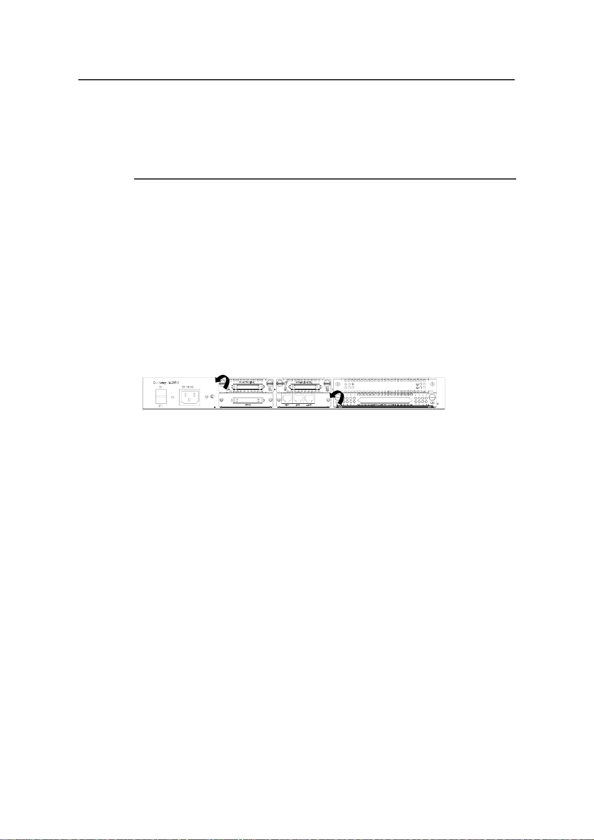
Following the rotating direction shown in this figure, remove the captive screws of the
blank filler panel using the flat-blade screwdriver.
Chapter 1 Overview
Figure 1-1 Removing the blank filler panel from a SIC slot
III. Installing SIC
Follow these steps to install a SIC:
Step 1: Place the rear panel of the Router towards you;
Step 2: Turn off the power switch of the Router and unplug the power cord;
Step 3: Take out the SIC and align its remote edge with the edge of the slot on the
Router’s rear panel;
Step 4: Push the SIC into the Router until it closely mates with the rear panel of the
Router;
Step 5: Fasten the SIC into the Router with captive screws;
Step 6: Power on the Router, and check the LEDs of the corresponding slot on the
front panel: after the initialization of the SIC, ON means that the SIC is operating
normally and OFF means that its Power-On Self-Test (POST) has failed. In the latter
case, please contact your agent.
1-4
Page 15

3Com Router 5000 and Router 6000 v2.41
Module Guide
Figure 1-2 Installing SIC
IV. Removing SIC
Follow these steps to remove a SIC:
Step 1: Place the rear panel of the Router towards you;
Chapter 1 Overview
Step 2: Turn off the power switch of the Router and unplug the power cord;
Step 3: Unplug all the network interface cables connected to the rear panel of the
Router;
Step 4: Remove the captive screws on both sides of the SIC using the flat-blade
screwdriver;
Step 5: Pull the SIC outward until it is completely taken out of the Router chassis.
1.5.2 Installing/Removing MIM
I. Tools required
z Flat-blade screwdriver
z ESD-preventive wrist strap and ESD-preventive glove
II. Installing MIM
Follow these steps to install a MIM:
Step 1: Place the rear panel of the Router towards you;
Step 2: Turn off the power switch of the Router and unplug the power cord;
Step 3: Select a slot and insert the MIM along the guides in the slot until it contacts the
rear panel of the Router;
Step 4: Fix the MIM into the Router with captive screws;
Step 5: Power on the Router, and check the LEDs of the corresponding slot on the
front panel: ON means that the MIM is operating normally and OFF means that the
POST of the MIM has failed. In the latter case, please contact your agent.
1-5
Page 16
3Com Router 5000 and Router 6000 v2.41
Module Guide
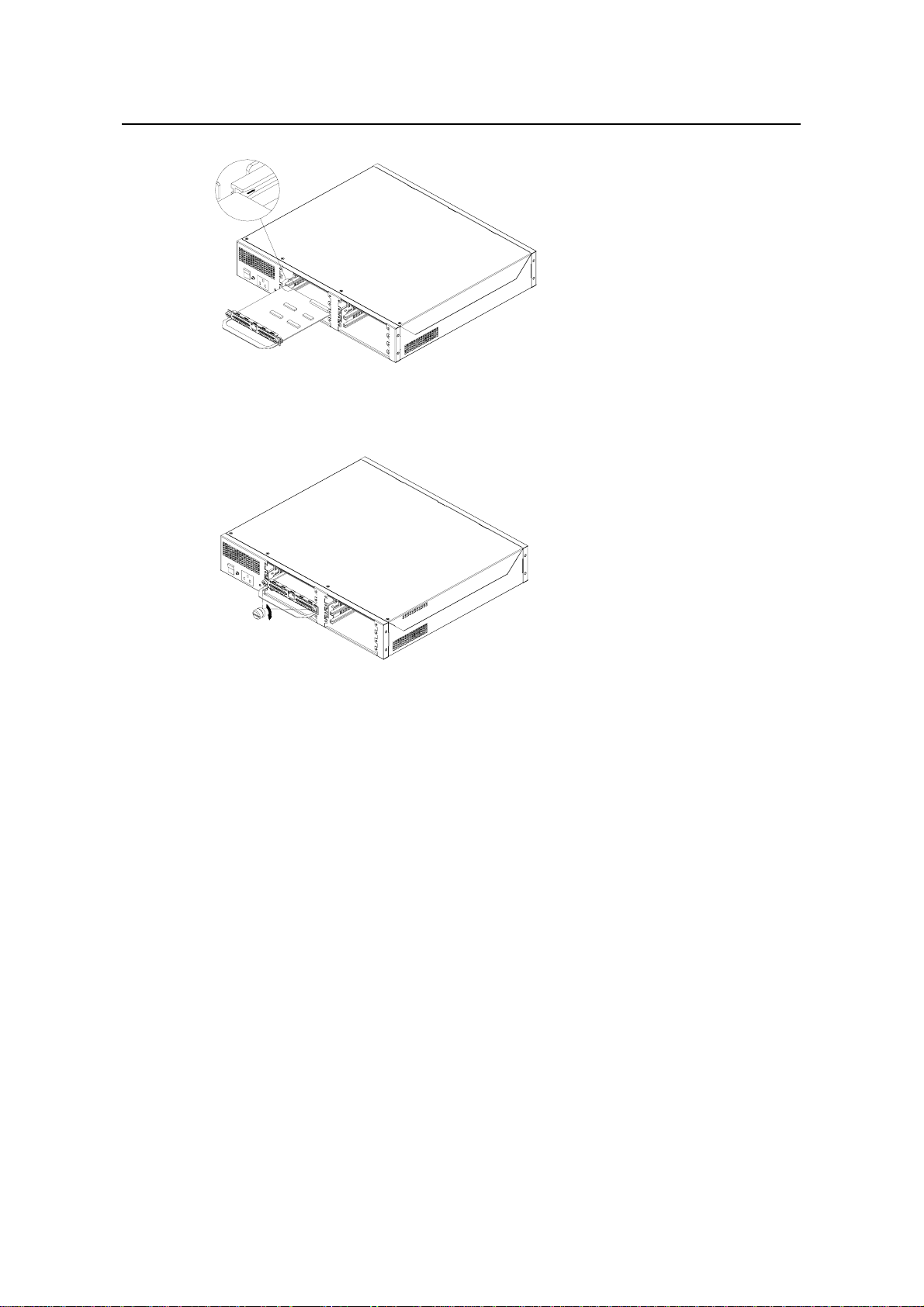
Figure 1-3 Installing MIM (1)
Chapter 1 Overview
Figure 1-4 Installing MIM (2)
III. Removing MIM
Follow these steps to remove a MIM:
Step 1: Place the rear panel of the Router towards you;
Step 2: Turn off the power switch of the Router and unplug the power cord;
Step 3: Unplug all interface cables from the rear panel of the Router;
Step 4: Loosen the captive screws at both sides of the MIM;
Step 5: Pull the MIM towards you until it is completely separated from the bottom of the
router.
1.5.3 Installing/Removing an FIC
Caution:
The EMI gaskets on the FIC panel can filter electromagnetic interference of the router.
Do not damage them when uninstalling or replacing an FIC.
If you do not install a new FIC after removing the old one, replace the blank filter panel
to keep off the dust and ensure adequate ventilation of the router.
1-6
Page 17

3Com Router 5000 and Router 6000 v2.41
Module Guide
Chapter 1 Overview
The router series supports hot swapping. Thus, you can remove or install FICs when
the router is running without disconnecting the power supply. But before that, you must
first execute the remove slot command; otherwise, unknown errors might occur. When
you replace the removed FICs, you do not need to execute the undo remove slot
command however.
If you execute the remove slot command inadvertently, you can cancel that operation
by using the undo remove slot command.
I. Tools required
ESD-preventive wrist strap
II. Removing an FIC
Step 1: Place the router with the front panel forward.
Step 2: Remove the cables connected to the FIC.
Step 3: Loosen the captive screws at both sides of the FIC.
Step 4: Push the ejector levers at both sides of the FIC outward, pull the FIC out of the slot
along the guides until disengaging it totally from the slot.
III. Installing an FIC
Step 1: Place the router with the front panel forward.
Step 2: Align the remote edge of the FIC with the slot edge, push it into the slot, push the
ejector levers inward until it presses against the FIC panel (the angles thus formed
between the FIC panel and the levers are the minimum angles).
Step 3: Fix the FIC in the chassis by fastening the captive screws.
Repeat these steps to install all the other FICs.
1.6 Troubleshooting
3Com 5000 Routers LEDs, indicate the state of the module as follows:
After the installation of a SIC/MIM, turn on the power and view the corresponding
LEDs (such as SLOT0, SLOT1 or SLOT2) on the cover of the Router chassis: ON
means that the SIC/MIM is operating normally and OFF means that the Power-On
Self-Test (POST) of the SIC/MIM has failed.
If the installed SIC/MIM is in abnormal state, check that:
z Proper interface cable is used;
z The LEDs on the panel of SIC/MIM are displaying normally (see the section
introducing the SIC/MIM for its LED status and description);
z The SIC/MIM accepts the configuration and works well using the display
command.
1-7
Page 18
3Com Router 5000 and Router 6000 v2.41
Module Guide
Chapter 2 Smart Interface Cards
Chapter 2 Smart Interface Cards (Router 5000)
2.1 Router 1-Port 10/100 SIC
1-port 10Base-T/100Base-TX Ethernet interface card, in which FE stands for Fast
Ethernet module. This is used to implement the communication between Routers and
LANs. It supports:
z Effective transmission distance of 100 meters with category-5 twisted pair cables;
z Operating speeds of both 100 Mbps and 10 Mbps and autosensing;
z Both full duplex (in common use) and half-duplex operating modes.
2.1.1 Interface Attributes
The interface attributes of Router 1-Port 10/100 SIC are given in the following table:
Table 2-1 Interface attributes of Router 1-Port 10/100 SIC
Attribute Router 1-Port 10/100 SIC
Connector type RJ-45
Interface type MDI
Number of connectors 1
Cable type Straight-through Ethernet cable
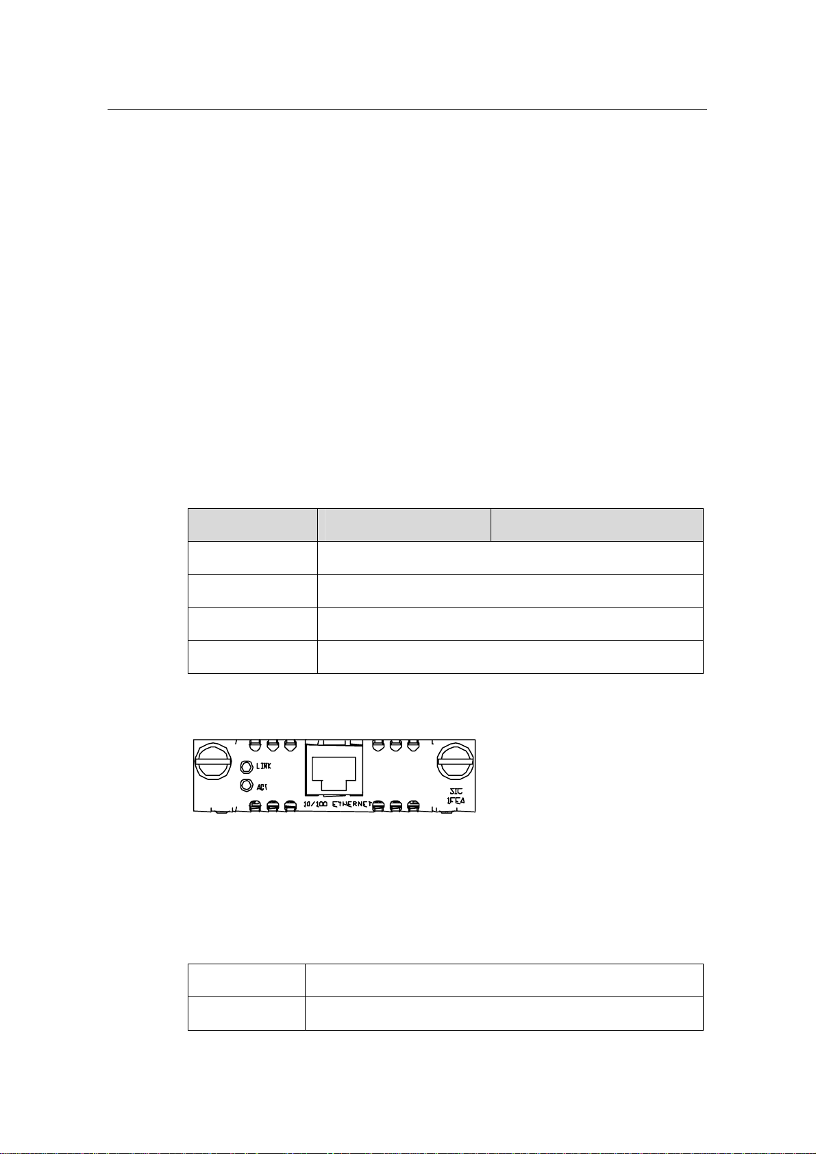
Router 1-Port 10/100 SIC panel is shown in the following figure:
Figure 2-1 Router 1-Port 10/100 SIC panel
The status description of the LEDs on Router 1-Port 10/100 SIC panel is listed in the
following table:
Table 2-2 Description of the LEDs on Router 1-Port 10/100 SIC panel
LINK OFF means no link is present; ON means a link is present.
ACT
OFF means no data is being transmitted or received; blinking means data is
2-1
Page 19
3Com Router 5000 and Router 6000 v2.41
Module Guide
being received or/and transmitted.
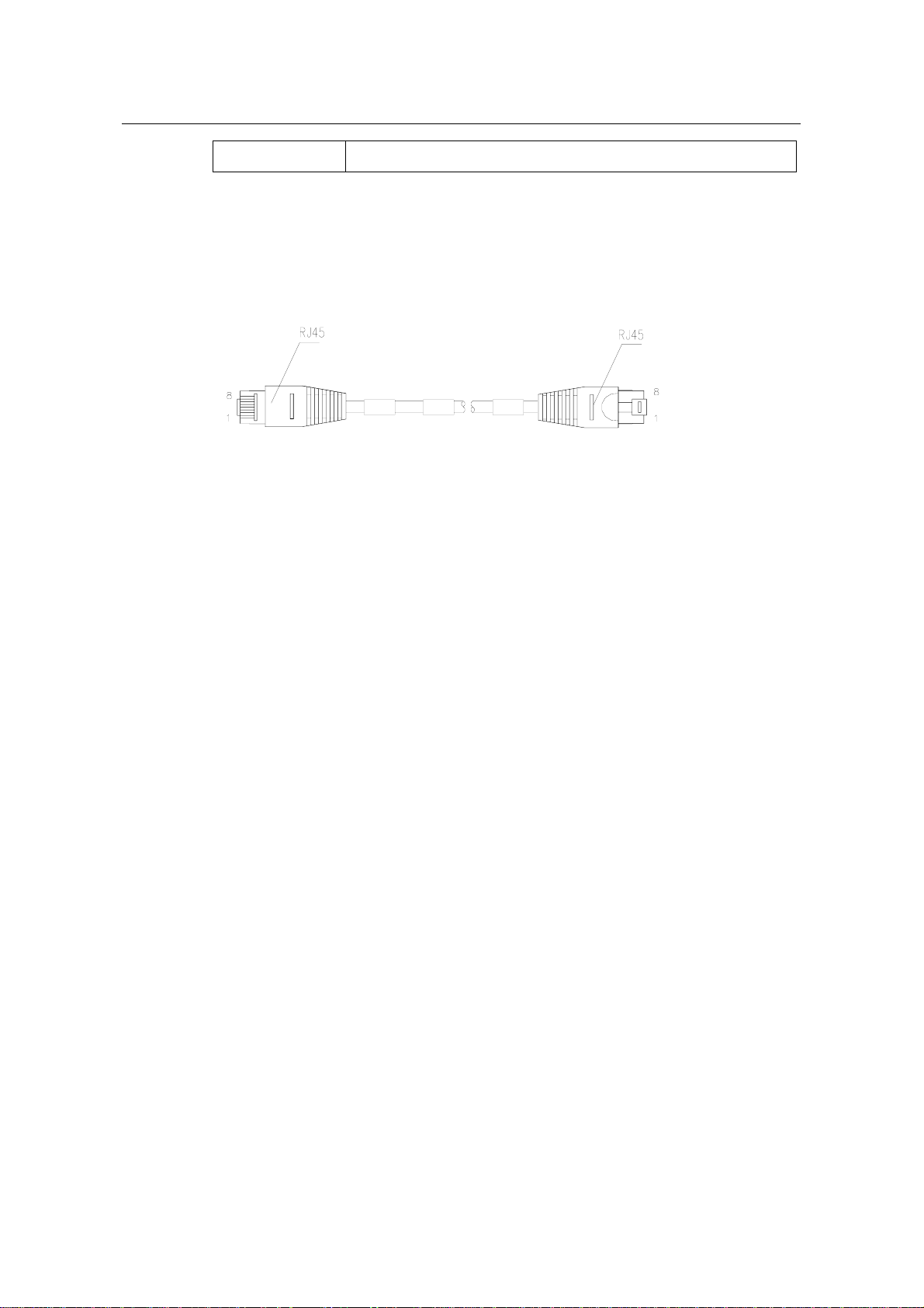
2.1.2 Interface Cable
Normally, category-5 twisted pair cable is adopted to connect the 10BASE-T
/100BASE-TX Ethernet interface to the Ethernet, as shown in the following figure:
Figure 2-2 Ethernet cable
Ethernet cables fall into two categories: straight-through cables and crossover cables,
specifically,
Chapter 2 Smart Interface Cards
z Straight-through cable: the wire sequences of the twisted pair cable crimped in
the RJ-45 connectors at both ends are completely the same. It is used to connect
terminal devices (such as PCs, routers) to Hubs or LAN Switches.
z Crossover cable: The wire sequences of twisted pair cable crimped in the RJ-45
connectors at both ends are different. It can be used to connect two terminal
devices (such as PCs and Routers). You can such kind of cables by yourself if
necessary.
2.1.3 Connecting the Interface Cable
If the SIC has been properly installed, follow these steps to connect the interface
cable:
Step 1: Connect the Ethernet port of SIC to a PC or router using a crossover cable and
to a Hub or LAN Switch using a straight-through cable;
Step 2: Power on the Router and check the SLOT1 LED on its front panel: ON means
that the SIC is operating normally and OFF means that the Power-On Self-Test (POST)
of the SIC has failed. In the latter case, please contact your agent.
Step 3: Check the status of LINK LED on the panel: ON means the link is connected
and OFF means the link is not connected. In the latter case, check the line.
2-2
Page 20

3Com Router 5000 and Router 6000 v2.41
Module Guide
2.2 Router 1-Port Serial SIC
2.2.1 Introduction
1-port multiprotocol synchronous/asynchronous serial interface card (Router 1-Port
Serial SIC) supports both synchronous and asynchronous operating modes. It
supports:
z Transmission/Receiving and handling of synchronous and asynchronous serial
data streams;
z Different operating modes, such as V.24/V.35 and DTE/DCE, depending on the
actual applications;
z Automatic external cable type detection without the need of manual configuration;
z Local loopback and remote loopback, facilitating fault test and location.
I. Synchronous and asynchronous
In different operating modes, a synchronous/asynchronous serial interface supports
different signal standards and baud rates and the maximum transmission distance of
the signals is related to the baud rate setting. For the relationships between cable type,
baud rate setting and signal transmission distance, see the following table.
Chapter 2 Smart Interface Cards
Table 2-3 Baud rate and transmission distance of V.24 (RS232)/V.35 cable
V.24 (RS232) V.35
Baud rate (bps)
Maximum
transmission
Distance (m)
Baud rate (bps)
Maximum
transmission
Distance (m)
2400 60 2400 1250
4800 60 4800 625
9600 30 9600 312
19200 30 19200 156
38400 20 38400 78
64000 20 56000 60
115200 10 64000 50
- - 2048000 30
2-3
Page 21

3Com Router 5000 and Router 6000 v2.41
Module Guide
Caution:
The baud rate cannot exceed 64 kbps if V.24 cable is used and the interface operates in synchronous
mode.
II. DTE and DCE
The synchronous serial interface supports both DTE (Data Terminal Equipment) and
DCE (Data Circuit-terminating Equipment) operating modes. Given that two devices
are directly connected, if one operates in the DTE mode, the other will operate in the
DCE mode. The DCE device provides the synchronous clock and specifies the
communicating rate. The DTE device receives the synchronous clock and
communicates at the specified rate. Generally, the Router is used as a DTE device. To
make sure that the device is a DTE or DCE, refer to the manual shipped with this
device. In addition, the following table may also help you to identify the type of the
device.
Chapter 2 Smart Interface Cards
Table 2-4 Typical DTE and DCE equipment
Equipment type Interface type Typical equipment
DTE Male PC, Router
DCE Female Modem, Multiplexer, CSU/DSU
Asynchronous serial interface is generally used as dialing port and connected to a
modem or a Terminal Adapter (TA). In this case, regardless of the operating mode of
the device, only an appropriate baud rate for the interface needs to be selected.
Synchronous serial interface is generally used for the direct connection to such a
device as DDN, frame relay, or X.25 switch.
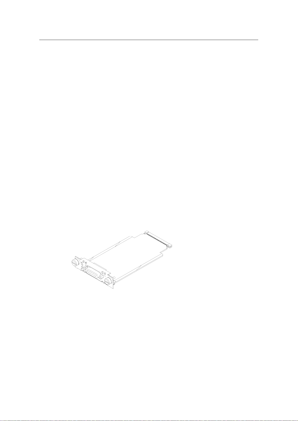
2.2.2 Appearance
Router 1-Port Serial SIC is illustrated in the following figure:
2-4
Page 22

3Com Router 5000 and Router 6000 v2.41
Module Guide
Figure 2-3 Router 1-Port Serial SIC
2.2.3 Interface Attributes
The interface attributes of Router 1-Port Serial SIC are given in the following table:
Table 2-5 Interface attributes of Router 1-Port Serial SIC
Attribute
Chapter 2 Smart Interface Cards
Description
Synchronous Asynchronous
Connector type DB50
Number of
connectors
1
V.24 (RS232) DTE cable
V.24 (RS232) DCE cable
Cable type
V.35 DTE cable
V.35 DCE cable
Interface standard
and Operating mode
Minimum baud rate
(bps)
Maximum baud rate
(bps)
V.24 V.35
DTE, DCE DTE DCE
1200 1200 1200 300
64K 4.096M 2.048M 115.2K
RS232
2-5
Page 23
3Com Router 5000 and Router 6000 v2.41
Module Guide
Attribute
Chapter 2 Smart Interface Cards
Description
Synchronous Asynchronous
Modem dial-up
Supported service
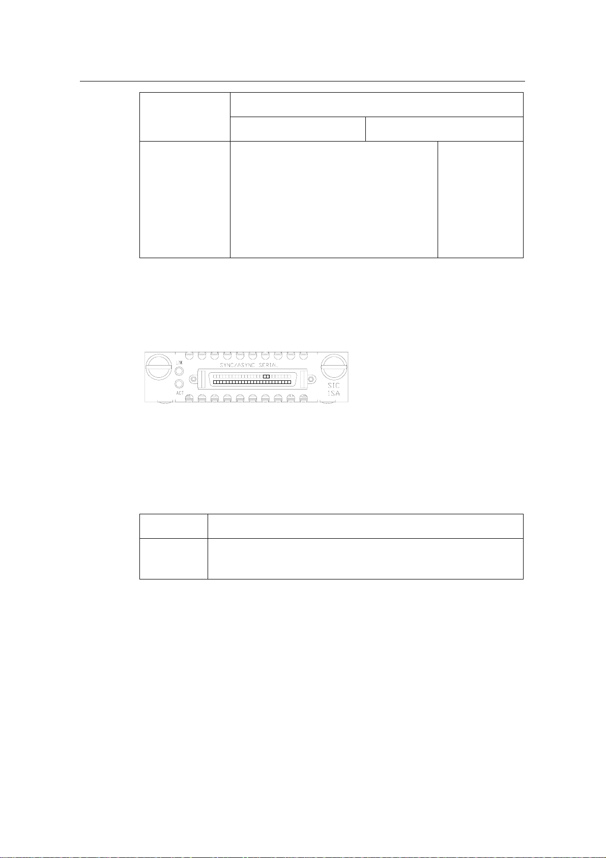
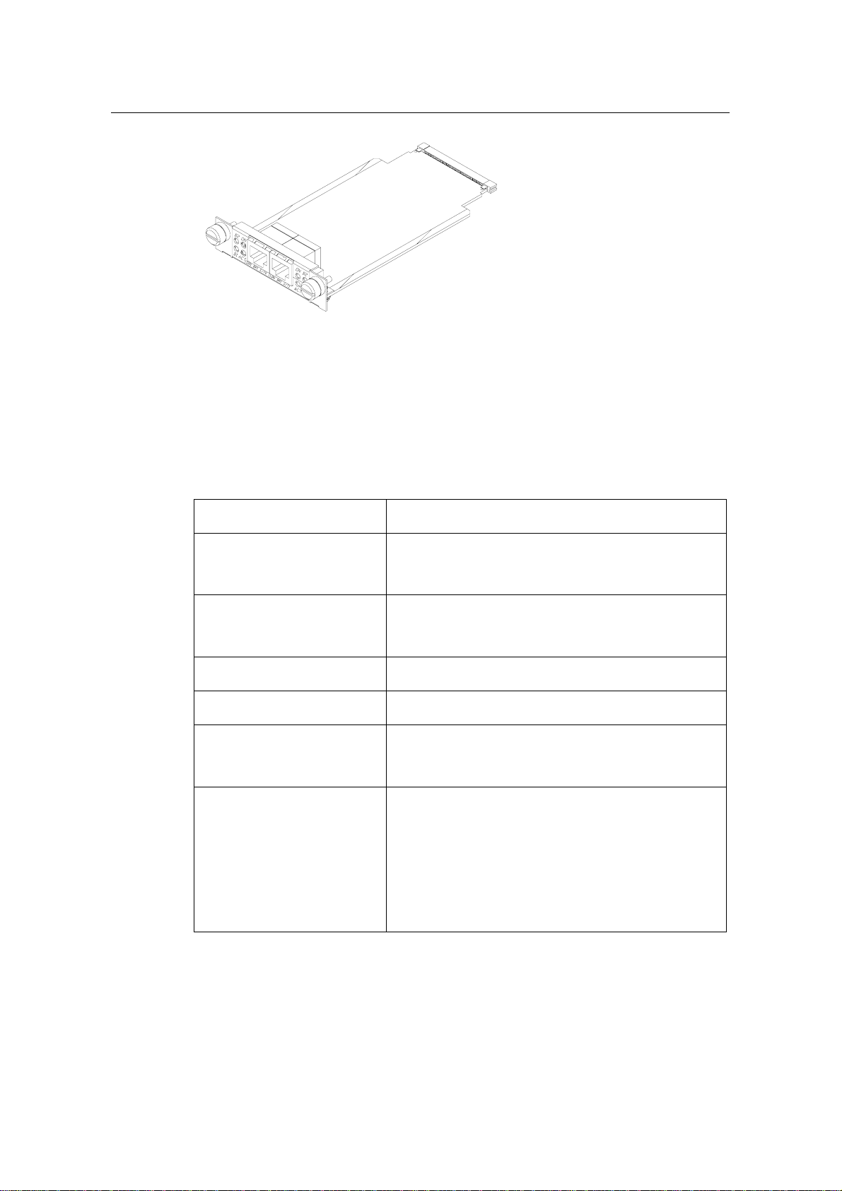
2.2.4 Interface LEDs
Router 1-Port Serial SIC panel is shown in the following figure:
Figure 2-4 Router 1-Port Serial SIC panel
The status description of the LEDs on Router 1-Port Serial SIC panel is listed in the
following table:
DDN leased line
Terminal access
Backup
Dumb terminal
access
Asynchronous
leased line
Backup
Table 2-6 Description of the LEDs on Router 1-Port Serial SIC panel
LINK OFF means no link is present; ON means a link is present.
ACT
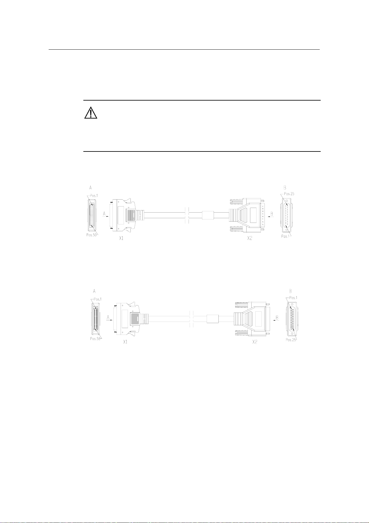
2.2.5 Interface Cable
Router 1-Port Serial SIC interface cables are synchronous/asynchronous serial
interface cables that fit into four types:
z V.24 (RS232) DTE cable, with DB25 (male) connector at the network end;
z V.24 (RS232) DCE cable, with DB25 (female) connector at the network end;
z V.35 DTE cable, with 34PIN (male) connector at the network end;
z V.35 DCE cable, with 34PIN (female) connector at the network end.
OFF means no data is being transmitted or received; blinking means data is being
received or/and transmitted.
2-6
Page 24
3Com Router 5000 and Router 6000 v2.41
Module Guide
At one end of these cables is DB50 connector for the connection to a router, and at the
other end (network end) is a connector whose type varies by the network device (or
line type) to be connected.
Caution:
The four types of cables listed above are optional, which must be selected while purchasing the Router
1-Port Serial SIC. Otherwise they will not be supplied.
z V.24 (RS232) DTE cable
Chapter 2 Smart Interface Cards
Figure 2-5 V.24 (RS232) DTE cable
z V.24 (RS232) DCE cable
Figure 2-6 V.24 (RS232) DCE cable
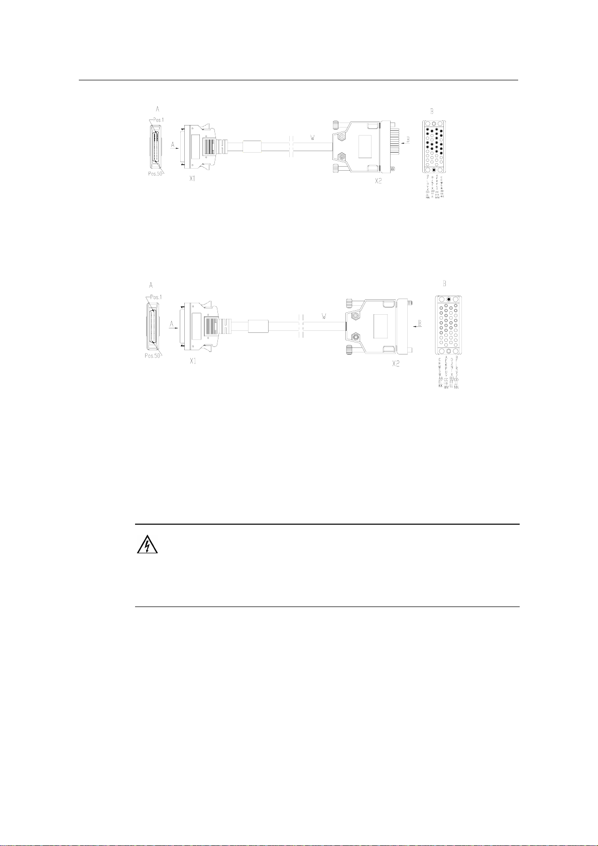
z V.35 DTE cable
2-7
Page 25
3Com Router 5000 and Router 6000 v2.41
Module Guide
Figure 2-7 V.35 DTE cable
z V.35 DCE cable
Chapter 2 Smart Interface Cards
Figure 2-8 V.35 DCE cable
For the pinouts of synchronous/asynchronous serial interface cable, see Low-End and
Mid-Range Series Routers Cable Manual.
2.2.6 Connecting Interface Cable
Warning:
Do not plug or unplug synchronous/asynchronous serial interface cables when the Router has power.
Otherwise, it is likely to damage the equipment and ports.
If the SIC has been properly installed, follow these steps to connect the
synchronous/asynchronous serial interface cable:
Step 1: Insert the DB50 connector of the cable into the DB50 port on the Router 1-Port
Serial SIC;
Step 2: Connect the other end of the cable to:
z CSU/DSU (a type of data transfer device), if the WAN is a DDN line, or
z Analog modem, if the WAN is a dial-up line.
2-8
Page 26
3Com Router 5000 and Router 6000 v2.41
Module Guide
Step 3: Power on the Router, and check the LEDs of the corresponding slot on the
front panel: ON means that the SIC is operating normally and OFF means that the
POST of the SIC has failed. In the latter case, please contact your agent;
Step 4: Check the status of LINK LED on the Router 1-Port Serial SIC panel: ON
means the link is connected and OFF means the link is not connected. In the latter
case, check the line.
Chapter 2 Smart Interface Cards
2.3 Router 2-Port ISDN-S/T SIC and Router 2-Port ISDN-U SIC
2.3.1 Introduction
1/2-port ISDN BRI S/T interface cards (Router 2-Port ISDN-S/T SIC) serve to
transmit/receive and handle one and two channels of ISDN BRI S/T data streams.
1/2-port ISDN BRI U interface cards (Router 2-Port ISDN-U SIC) server to
transmit/receive and handle one and two channels of ISDN BRI U data streams.
Both Router 2-Port ISDN-S/T SIC and Router 2-Port ISDN-U SIC have two types of
operating modes: dial-up and leased line.
2.3.2 Appearance
Router 2-Port ISDN-S/T SIC and Router 2-Port ISDN-U SIC are shown in the following
figures:
Figure 2-9 Router 2-Port ISDN-S/T SIC
2-9
Page 27
3Com Router 5000 and Router 6000 v2.41
Module Guide
Figure 2-10 Router 2-Port ISDN-U SIC
2.3.3 Interface Attributes
The interface attributes of Router 2-Port ISDN-S/T SIC and Router 2-Port ISDN-U SIC
are given in the following table:
Table 2-7 Interface attributes of Router 2-Port ISDN-S/T SIC and Router 2-Port ISDN-U SIC
Chapter 2 Smart Interface Cards
Attribute Description
RJ45 (Router 2-Port ISDN-S/T SIC)
Connector type
RJ45 (Router 2-Port ISDN-U SIC, compatible with RJ11)
1
Number of connectors
2
Cable type Telephone cable with ferrite core
Protocol standard ITU-T I.430, Q.921, Q.931 Recommendations
ISDN dial-up mode
Operating mode
ISDN leased line mode
ISDN
ISDN complementary services
Supported service
Multi-user number
Sub-address
Backup
2.3.4 Interface LEDs
Router 2-Port ISDN-S/T SIC and Router 2-Port ISDN-U SIC panels are shown in the
following figures:
2-10
Page 28

3Com Router 5000 and Router 6000 v2.41
Module Guide
Figure 2-11 SIC-2BS panel
Figure 2-12 SIC-2BU panel
The status description of the LEDs is given in the following table:
Table 2-8 Description of the LEDs on SIC-BS and SIC-BU panels
LED Description
Chapter 2 Smart Interface Cards
B1
B2
ACT
OFF means B1 channel is idle. Blinking means B1 channel is occupied and
data communication is being conducted.
OFF means B2 channel is idle. Blinking means B2 channel is occupied and
data communication is being conducted.
OFF means deactivation. Blinking means activating process. ON means
active status.
OFF means the power to the SIC is disconnected (caused by the failure of
ON
power supply to the SIC and so on). ON means the SIC is normally
powered on.
Note:
For ISDN, “active” describes the action or process that a terminal device synchronizes the network clock.
It belongs to the physical layer category. In order to decrease power consumption of exchange device
and etc., usually the terminals and network (LT port) should be “deactivated”.
2.3.5 Interface Cable
Both of Router 2-Port ISDN-S/T SIC and Router 2-Port ISDN-U SIC use the telephone
cable with ferrite core.
2-11
Page 29

3Com Router 5000 and Router 6000 v2.41
Module Guide
Caution:
The relevant cables have been included in the standard configurations of Router 2-Port ISDN-S/T SIC
and Router 2-Port ISDN-U SIC.
2.3.6 Connecting Interface Cable
Caution:
z You should connect a cable to the port with the correct mark. Misplugging is prone to impair the
SIC/MIM and even damage the router.
z When using a telephone cable with ferrite core outdoors, you are recommended to install a special
lightning arrester on the input end of the cable in order to avoid lightning more effectively.
Chapter 2 Smart Interface Cards
If the SIC has been properly installed, follow these steps to connect the cable:
Step 1: Confirm the type of the ISDN line provided by your telecom service provider;
Step 2: Connect the cable;
z For Router 2-Port ISDN-S/T SIC
If the ISDN U interface is adopted for the line, use NT1 for conversion. The connecting
procedure is to insert one end of the telephone cable with ferrite core into the BRI S/T
interface of Router 2-Port ISDN-S/T SIC and the other end into the NT1.
If the line uses the ISDN S/T interface, directly insert the cable with ferrite core into the
BRI S/T interface of the Router 2-Port ISDN-S/T SIC and the other end into the ISDN
S/T interface.
z For Router 2-Port ISDN-U SIC
If the ISDN U interface is adopted for the line, directly insert the cable with ferrite core
into the BRI U interface of the Router 2-Port ISDN-U SIC and the other end into the
ISDN U interface.
If the line uses the ISDN S/T interface, contact the agent and replace the SIC with
Router 2-Port ISDN-S/T SIC.
Step 3: Power on the Router, and check the corresponding Related LED on the front
panel of the Router. If the LED is ON, it indicates that the SIC has passed the self-test
and can operate normally. If the LED is OFF, it indicates the failure of the self-test. In
such a case, please contact your agent.
2-12
Page 30
3Com Router 5000 and Router 6000 v2.41
Module Guide
Step 4: Check the LED on the SIC panel: ON means the SIC is normally powered on.
If it is OFF, contact the agent.
Chapter 2 Smart Interface Cards
2.4 Router 1-Port Fractional E1 SIC
2.4.1 Introduction
1-port channelized E1/cE1/PRI compatible interface card supports:
z Transmission/Receiving and handling of E1 data streams;
z CE1 (channelized E1) access;
z ISDN PRI function;
z Remote loopback and local loopback functions, facilitating fault test and location.
It is possible to use the card for multiple purposes through different configurations.
Following are the differences between SIC-EPRI and 1-port Fractional E1 interface
card (Router 1-Port Fractional E1 SIC):
z FE1 mode of Router 1-Port Fractional E1 SIC can support only one channel
bundle (the rate is n x 64kbps, n=1-31), while the 31 channels can be grouped
into multiple arbitrary bundles by SIC-EPRI;
z Router 1-Port Fractional E1 SIC does not support PRI mode.
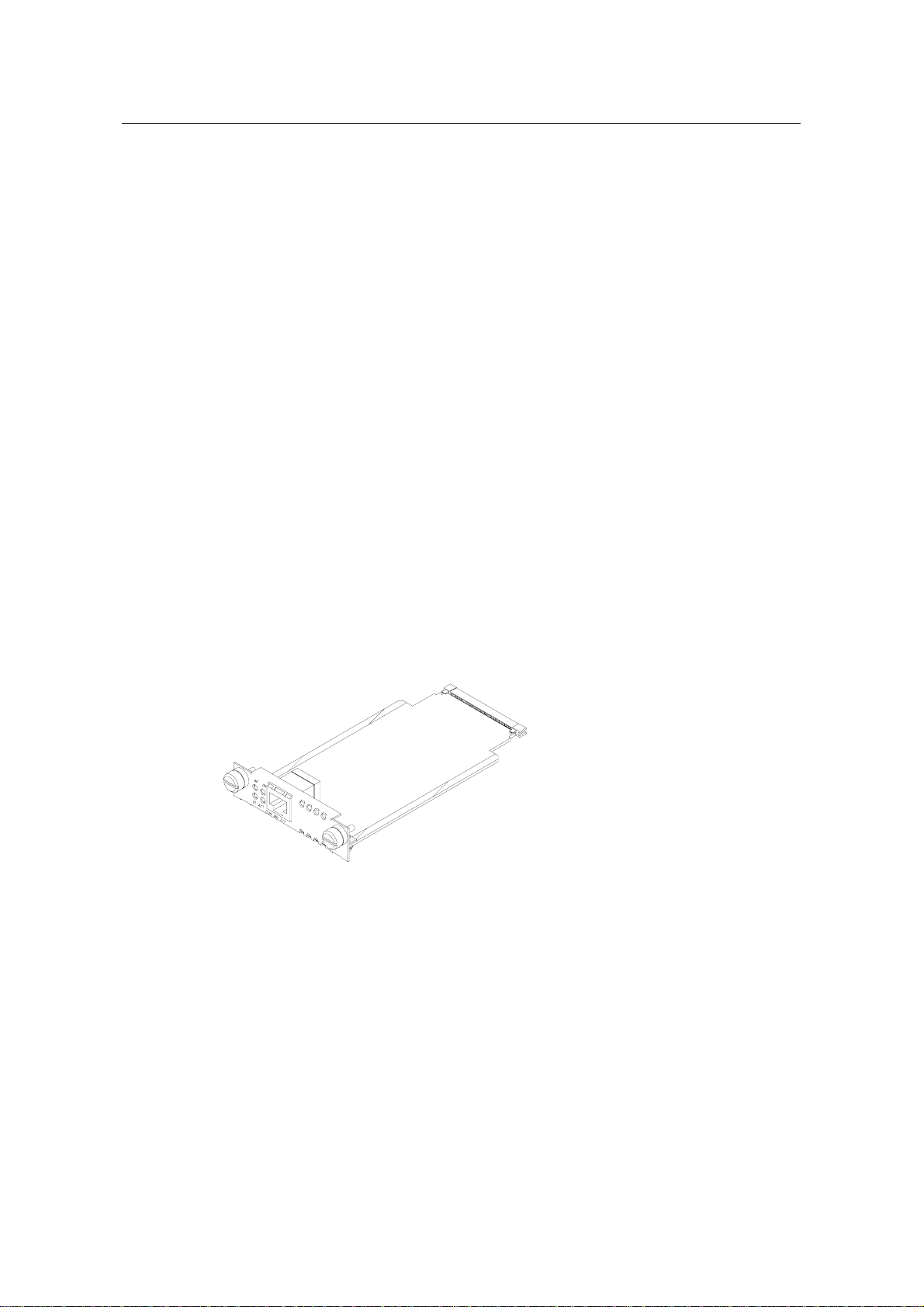
2.4.2 Appearance
Figure 2-13 Router 1-Port Fractional E1 SIC
2.4.3 Interface Attributes
The interface attributes of Router 1-Port Fractional E1 SIC are given in the following
table:
2-13
Page 31

3Com Router 5000 and Router 6000 v2.41
Module Guide
Table 2-9 Interface attributes of Router 1-Port Fractional E1 SIC
Attribute Description
Connector type DB15
Number of connectors 1
Interface standard G.703, G.704
Interface rate 2.048Mbps
75-ohm non-balanced coaxial cable (DB15 to BNC)
Chapter 2 Smart Interface Cards
Cable type
Operating mode
Supported service
2.4.4 DIP Switch
E1/cE1/PRI interface is compatible with both 75-ohm impedance and 120-ohm
impedance. The interface matches different types of impedance through an 8BIT DIP
switch. By default, all the 8 positions of the DIP switch are ON, as shown in the
following figure:
120-ohm balanced twisted-pair cable (DB15 to RJ45)
Coaxial connector, network interface connector and 75-ohm to 120-ohm
adapter
E1
cE1, ISDN PRI (supported by SIC-EPRI only )
FE1(supported by Router 1-Port Fractional E1 SIC only)
Backup
Terminal access
ISDN (supported by SIC-EPRI only)
2-14
Page 32

3Com Router 5000 and Router 6000 v2.41
Module Guide
on
1
2
3
4
5
6
7
8
Figure 2-14 Default setting of the DIP switches
8BIT description and settings of DIP switch are given in the following table:
Table 2-10 Description and settings of the internal DIP switch of SIC-ERRI/Router 1-Port Fractional E1
SIC
Chapter 2 Smart Interface Cards
DIP switch Description
75 -ohm
impedance
120 -ohm impedance
1BIT ON OFF
2BIT ON OFF
Switch for
3BIT ON OFF
75-ohm/120-ohm
options
4BIT ON OFF
5BIT
ON OFF
OFF: RxRing
grounding via
6BIT
Switch for RxRing
grounding mode options
capacitor
-
ON: RxRing directly
grounding
ON: RxShield grounding
7BIT
Switch for RxShield
grounding options
-
OFF: RxShield
ungrounding
2-15
Page 33

3Com Router 5000 and Router 6000 v2.41
Module Guide
Chapter 2 Smart Interface Cards
DIP switch Description
8BIT
Caution:
z When setting internal DIP switch, you are recommended to: turn ON all BITs from 1 to 8 when a
75-ohm cable is connected. Turn OFF all BITs from 1 to 8 when a 120-ohm cable is connected;
z The default configuration of internal DIP switch is that all the 8 positions of the BIT switch are ON,
that is, the E1 interface impedance is 75-ohm.
2.4.5 Interface LEDs
Switch for RxShield
grounding options
impedance
-
75 -ohm
120 -ohm impedance
OFF: RxShield grounding
via capacitor
ON: RxShield directly
grounding
Router 1-Port Fractional E1 SIC panel is shown in the following figure:
Fractional E1
Figure 2-15 Router 1-Port Fractional E1 SIC panel
The status description of the LEDs is given in the following table:
Table 2-11 Description of the LEDs on Router 1-Port Fractional E1 SIC panel
LED Description
OFF means the link is not connected. ON means the link is connected and
LINK
can correctly receive carrier (E1 mode) or frame synchronous signals
(cE1/PRI or FE1).
ACT
OFF means no data is being transmitted or received; blinking means data is
being received or/and transmitted.
2-16
Page 34

3Com Router 5000 and Router 6000 v2.41
Module Guide
2.4.6 Interface Cable
Interface cables for Router 1-Port Fractional E1 SIC are standard E1 G.703 cables. E1
G.703 cables have two types: 75-ohm non-balanced coaxial cables and 120-ohm
balanced twisted pair cables, shown as follows:
z 75-ohm non-balanced coaxial cable
Enlarged A side
Pos.1
DB15 Male
Magnetic core
Label
Chapter 2 Smart Interface Cards
BNC connector
Cable tie
A
Pos.15
HUAWEI
Hot-shrinkable tube
Figure 2-16 E1 G.703 75-ohm non-balanced coaxial cable
75-ohm non-balanced coaxial cable connects Router 1-Port Fractional E1 SIC with the
DB15 connector and the network end with the BNC connector.
Note:
A pair of coaxial connectors are available for extending the E1 cable. Both ends of the connectors are
BNC receptacles that can be used to connect two 75-ohm non-balanced coaxial cables with BNC
connectors.
z 120-ohm balanced twisted pair cable
Figure 2-17 E1 G.703 120-ohm balanced twisted pair cable
120-ohm balanced twisted pair cable connects Router 1-Port Fractional E1 SIC with
the DB15 connector and network end with the RJ45 connector.
2-17
Page 35

3Com Router 5000 and Router 6000 v2.41
Module Guide
Note:
A network interface connector is available for extending the E1 cable. Both ends of the connector are
RJ45 jacks that can be used to connect two 120-ohm balanced twisted pair cables.
In addition, a 75-ohm to 120-ohm adapter is available.
For the pinouts of E1 cables, see Low-End and Mid-Range Series Routers Cable
Manual.
Caution:
E1 cable, coaxial connector, network interface connector and 75ohm-to-120ohm adapter are optional,
which must be ordered together with Router 1-Port Fractional E1 SIC. Otherwise they will not be
supplied.
Chapter 2 Smart Interface Cards
2.4.7 Connecting Interface Cable
Caution:
When using E1 cable outdoors, you are recommended to install a special lightning arrester on the input
end of the cable in order to avoid lightning more effectively.
If the SIC has been properly installed, follow these steps to connect the cable:
Step 1: Check the type of E1 cable and correctly set the DIP switch (the ex-factory
setting of E1/cE1/PRI interface impedance is 75-ohm);
Step 2: Connect the DB15 connector of E1 cable to Router 1-Port Fractional E1 SIC;
Step 3: Connect the other end of the E1 cable to the corresponding network device:
1) When the E1 cable is a 75-ohm unbalanced coaxial cable:
z Directly connect the BNC connector of the cable to the remote equipment if there
is no need for extension, or
z Connect the BNC connector of the cable to the coaxial connector and the other
end of the coaxial connector to the remote network equipment through a 75-ohm
E1 trunk cable, if cable extension is needed.
2-18
Page 36

3Com Router 5000 and Router 6000 v2.41
Module Guide
Caution:
The wire marked TX in the E1 cable should be connected to the peer wire marked RX and the wire
marked RX should be connected to the peer wire marked TX.
DB-15
Chapter 2 Smart Interface Cards
Network
devices
such as DDN
Router
Coaxial connector
75-ohm non-balanced coaxial cable
BNC
BNC
75-ohm E1 trunk cable
Figure 2-18 Extending an E1 75-ohm non-balanced coaxial cable
If the remote device has 120-ohm interface, it is needed to use a 75-ohm-to-120-ohm
adapter or use a 120-ohm cable.
2) When the E1 cable is a 120-ohm balanced twisted pair cable:
z Directly connect the RJ45 connector of the cable to the RJ45 port of the remote
equipment, if there is no need to extend the E1 cable, or
z Connect the RJ45 connector of the cable to the network connector and the other
end of the network connector to the network equipment through a 120-ohm E1
trunk cable, if cable extension is needed.
DB-15
Network
devices such
as DDN
Router
Network interface connector
120-ohm balanced twisted pair
RJ-45
RJ-45
120-ohm E1 trunk cable
Figure 2-19 Extending an E1 120-ohm balanced twisted pair cable
Step 4: Power on the Router, and check the LEDs of the corresponding slot on the
front panel: ON means that the SIC is operating normally and OFF means that the
Power-On Self-Test (POST) of the SIC has failed. In the latter case, please contact
your agent;
2-19
Page 37

3Com Router 5000 and Router 6000 v2.41
Module Guide
Step 5: Check the status of LINK LED on the Router 1-Port Fractional E1 SIC panel:
ON means the link is connected and OFF means the link is not connected. In the latter
case, check the line.
Chapter 2 Smart Interface Cards
2.5 Router 1-Port Fractional T1 SIC
2.5.1 Introduction
1-port channelized T1/cT1/PRI compatible interface card supports:
z Transmission/Receiving and handling of T1 data streams;
z cT1 (channel T1) access;
z ISDN PRI function;
z Remote loopback and local loopback, facilitating the effective and flexible
debugging.
It is possible to use the card for multiple purposes through different configurations.
Following are the differences between and 1-port Fractional T1 interface card (Router
1-Port Fractional T1 SIC):
z FT1 mode of Router 1-Port Fractional T1 SIC can support only one channel
bundle (the rate is n x 56 kbps, n=1-24), while the 24 channels can be grouped
into multiple arbitrary bundles by SIC-TPRI.
z Router 1-Port Fractional T1 SIC does not support PRI mode.
2.5.2 Appearance
Figure 2-20 Router 1-Port Fractional T1 SIC
2.5.3 Interface Attributes
The interface attributes of Router 1-Port Fractional T1 SIC are given in the following
table:
2-20
Page 38

3Com Router 5000 and Router 6000 v2.41
Module Guide
Table 2-12 Interface attributes of Router 1-Port Fractional T1 SIC
Attribute Description
Connector type RJ45
Number of connectors 1
Interface standard G.703/T1.102, G.704
Interface rate 1.544Mbps
Cable type T1 cable (100-ohm standard shielded network cable)
Chapter 2 Smart Interface Cards
Operating mode
Supported service
2.5.4 Interface LEDs
Router 1-Port Fractional T1 SIC panel is shown in the following figure:
Figure 2-21 Router 1-Port Fractional T1 SIC panel
cT1, ISDN PRI
FT1(supported by Router 1-Port Fractional T1 SIC only)
Backup
Terminal access
ISDN (supported by SIC-TPRI ony)
Fractional T1
The status description of the LEDs is given in the following table:
Table 2-13 Description of the LEDs on Router 1-Port Fractional T1 SIC panel
LED Description
OFF means the link is not connected. ON means the link is
LINK
connected and frame synchronization signal can be correctly
received.
ACT
OFF means no data is being transmitted or received; blinking
means data is being received or/and transmitted.
2-21
Page 39

3Com Router 5000 and Router 6000 v2.41
Module Guide
2.5.5 Interface Cable
Router 1-Port Fractional T1 SIC interface cable is 100-ohm standard shielded network
cable that has RJ45 connectors at both ends. The following figure illustrates a Router
1-Port Fractional T1 SIC interface cable:
Figure 2-22 T1 cable
For the pinouts of T1 cable, see Low-End and Mid-Range Series Routers Cable
Manual.
Chapter 2 Smart Interface Cards
Caution:
Relevant cables are included in the standard shipment package of Router 1-Port Fractional T1 SIC.
2.5.6 Connecting Interface Cable
Caution:
z You should connect a cable to the port with the correct mark. Misplugging is prone to impair the
SIC/MIM and even damage the router.
z When using T1 cable outdoors, you are recommended to install a special lightning arrester on the
input end of the cable so as to avoid lightning more effectively.
If the SIC has been properly installed, follow these steps to connect the cable:
Step 1: Connect one end of the T1 cable to the RJ45 port of Router 1-Port Fractional
T1 SIC;
Step 2: Connect the other end of the T1 cable to the relevant equipment;
2-22
Page 40

3Com Router 5000 and Router 6000 v2.41
Module Guide
Step 3: Power on the Router, and check the LEDs of the corresponding slot on the
front panel: ON means that the SIC is operating normally and OFF means that the
POST of the SIC has failed. In the latter case, please contact your agent.
Step 4: Check the status of LINK LED on the Router 1-Port Fractional T1 SIC panel:
ON means the link is connected and OFF means the link is not connected. In the latter
case, check the line.
Chapter 2 Smart Interface Cards
2.6 Router 1-Port Analog Modem SIC
2.6.1 Introduction
1/2-port analog modem interface card (Router 1-Port Analog Modem SIC) integrates
the functions of asynchronous interface and external modem, that is, allowing 1/2
channel(s) of remote modem subscribers to directly access the Router. They support:
z Data rate of 56 kbps.
z Accessing and handling analog signals and transmitting the processed data to
the Router host through the serial interface bus. And also, processing the data
received from the host and then transmitting them to the PSTN via the telephone
port.
2.6.2 Appearance
Router 1-Port Analog Modem SIC and are shown in the following figures:
Figure 2-23 Router 1-Port Analog Modem SIC
2.6.3 Interface Attributes
The interface attributes of Router 1-Port Analog Modem SIC are given in the following
table:
Table 2-14 Interface attributes of Router 1-Port Analog Modem SIC
Attribute Description
Connector type RJ11
2-23
Page 41

3Com Router 5000 and Router 6000 v2.41
Module Guide
Attribute Description
Chapter 2 Smart Interface Cards
Number of connectors
Cable type Telephone cable with ferrite core
Maximum speed 56kbps
Supported standard
Supported service
2.6.4 Interface LEDs
Figure 2-24 Router 1-Port Analog Modem SIC panel
1 (Router 1-Port Analog Modem SIC)
2 ()
ITU-T V.90, V.34 (33.6 kbps), V.FC, V.32 bis, V.32, V.22 bis,
V.22A/B, V.23, V.21, Bell 212A a, Bell 103.
Modem dial-up
Table 2-15 Description of the LEDs on Router 1-Port Analog Modem SIC panel
LED Description
LINK
ACT
2.6.5 Interface Cable
The connection cables for Router 1-Port Analog Modem SIC are telephone cables with
ferrite core. Both ends of the cables are RJ11 connectors. For cable pinouts, refer to
Low-End and Mid-Range Series Routers Cable Manual.
Caution:
OFF means the link is idle. ON means the connection has been established.
Blinking means the connection is being set up.
OFF means the link is idle. Blinking means data is being transmitted or
received.
Relevant cables are included in the standard shipment package of Router 1-Port Analog Modem SIC.
2-24
Page 42

3Com Router 5000 and Router 6000 v2.41
Module Guide
2.6.6 Connecting Interface Cable
Caution:
z You should connect a cable to the port with the correct mark. Misplugging is prone to impair the
SIC/MIM and even damage the router.
z You are recommended to install a special lightning arrester on the input end of the telephone line in
order to avoid the lightning effects more efficiently.
If the SIC has been properly installed, follow these steps to connect the cable:
Step 1: Insert the end with ferrite core into one LINE port of Router 1-Port Analog
Modem SIC;
Chapter 2 Smart Interface Cards
Step 2: Plug the other end of the cable into the telephone wall jack;
Step 3: Power on the Router, and check the LEDs of the corresponding slot on the
front panel: ON means that the SIC is operating normally and OFF means that the
POST of the SIC has failed. In the latter case, please contact your agent.
2.7 Router 1-Port FXS SIC/FXO SIC and Router 2-Port FXS SIC/FXO SIC
2.7.1 Introduction
1/2-port voice subscriber circuit interface card (Router 1 or 2-Port FXS SIC) and
1/2-port voice AT0 analog trunk interface card (Router 1 or 2-Port FXO SIC) serve to
access and handle 1/2 channel(s) of analog voice signals over data communication
networks. The differences between FXS SIC and FXO SIC are listed below:
z FXS SIC cards are analog subscriber line cards that provide ordinary analog
z FXO SIC cards are loop trunk cards that provide access of common subscriber
telephone and fax access and also can connect AT0 loop trunks of exchanges;
lines of exchanges.
2-25
Page 43

3Com Router 5000 and Router 6000 v2.41
Module Guide
Caution:
While using FXS SIC/FXO SIC, you must ensure that the 3Com Routers can be connected to IP
networks or other WANs.
2.7.2 Appearance
z Router 1-Port FXS/FXO SIC
Chapter 2 Smart Interface Cards
Figure 2-25 Router 1-Port FXS/FXO SIC
z Router 2-Port FXS/FXO SIC
Figure 2-26 Router 2-Port FXS/FXO SIC
2.7.3 Interface Attributes
The interface attributes of Router 1-Port FXS/FXO SIC and Router 2-Port FXS/FXO
SIC are given in the following table:
2-26
Page 44

3Com Router 5000 and Router 6000 v2.41
Module Guide
Table 2-16 Interface attributes of Router 1-Port FXS/FXO SIC and Router 2-Port FXS/FXO SIC
Attribute Description
Connector type RJ11
Chapter 2 Smart Interface Cards
Number of connectors
Interface standard
Cable type Telephone cable with ferrite core.
Dialing mode Supports DTMF, not supports pulse dial-up.
Bandwidth 300 to 3400Hz
2.7.4 Interface LEDs
z Router 1-Port FXS/FXO SIC panel
1 (Router 1-Port FXS/FXO SIC)
2 (Router 2-Port FXS/FXO SIC)
Subscriber circuit interface (Router 1 or 2-Port FXS SIC)
compliant with ITU Q.512.
Loop trunk interface (SIC-1FXO/SIC-2FXO) compliant with ITU
Q.552.
Over-current and over-voltage protection compliant with ITU
K.20
Figure 2-27 Router 1-Port FXS SIC panel
Figure 2-28 Router 1-Port FXO SIC panel
z Router 2-Port FXS/FXO SIC panel
2-27
Page 45

3Com Router 5000 and Router 6000 v2.41
Module Guide
Figure 2-29 Router 2-Port FXS SIC panel
Figure 2-30 Router 2-Port FXO SIC panel
The status description of the LEDs of Router 1-Port FXS/FXO SIC and Router 2- Port
FXS/FXO SIC is shown in the following table:
Table 2-17 Description of the LEDs on Router 1-Port FXS/FXO SIC and Router 2-Port FXS/FXO SIC
panels
Chapter 2 Smart Interface Cards
LED Description
LINK
ACT
2.7.5 Interface Cable
Connection cables for Router 1-Port FXS/FXO SIC and Router 2- Port FXS/FXO SIC
are telephone cables with ferrite core. Both ends of the cables are RJ11 connectors.
For cable pinouts, see Low-End and Mid-Range Series Routers Cable Manual.
Caution:
The standard shipment package of Router 1-Port FXS/FXO SIC and Router 2-Port FXS/FXO SIC
includes a ferrite core telephone cable.
OFF means the link is idle. ON means the link is being occupied for call
connection.
OFF means the link is idle. ON means the link is being occupied for
communication.
2.7.6 Connecting Interface Cable
2-28
Page 46

3Com Router 5000 and Router 6000 v2.41
Module Guide
Caution:
z You should connect a cable to the port with the correct mark. Misplugging is prone to impair the
SIC/MIM and even damage the router.
z When the telephone cable is used outdoors, it is recommended that users install a special lightning
arrester on the input end of the cable in order to avoid the lightning effects more efficiently.
z One end of the telephone cable has a ferrite core. To ensure the compatibility of the Router, users
should connect the end with the ferrite core to the Router.
If the SIC is properly installed, follow these steps to connect the cable:
Step 1: Connect the end with the ferrite core to a RJ11 port of FXS/FXO SIC ;
Step 2: Insert the other end to
z a telephone or fax or the AT0 loop trunk if a Router 1 or 2-Port FXS SIC is
installed;
z a subscriber line of exchange if a Router 1 or 2-Port FXO SIC is installed;
Chapter 2 Smart Interface Cards
Step 3: Power on the Router, and check the LEDs of the corresponding slot on the
front panel: ON means that the SIC is operating normally and OFF means that the
POST of the SIC has failed. In the latter case, please contact your agent.
2.8 Router 1-Port SAE SIC
2.8.1 Introduction
Router 1-Port SAE SIC, 1-port enhanced high-speed sync/async serial interface card,
provides functions similar to SA, but its serial interfaces support more protocols, such
as RS449, X.21, and RS530.
2.8.2 Interface Attributes
The interface attributes of the Router 1-Port SAE SIC are given in the following table:
Table 2-18 Interface attributes of the Router 1-Port SAE SIC
Attribute
Description
Synchronous Asynchronous
Connector DB-28
Number of connectors 1
Interface standard and
V.24 V.35, RS449, X.21, RS530 RS232
2-29
Page 47

3Com Router 5000 and Router 6000 v2.41
Module Guide
Attribute
Chapter 2 Smart Interface Cards
Description
Synchronous Asynchronous
operating mode
Minimum baud rate
(bps)
Maximum baud rate
(bps)
Cable
DTE, DCE DTE, DCE
1200 1200 300
64 k 2.048 M 115.2
V.24 (RS232) DTE cable
V.24 (RS232) DCE cable
V.35 DTE cable
V.35 DCE cable
X.21 DTE cable
X.21 DCE cable
RS449 DTE cable
RS449 DCE cable
RS530 DTE cable
Services supported
2.8.3 Interface LEDs
Router 1-Port SAE SIC panel is shown in the following figure:
RS530 DCE cable
1) DDN leased line
2) Terminal access service
1) Dialup through
modems
2) Backup
3) Async leased
line
4) Terminal access
Figure 2-31 Router 1-Port SAE SIC panel
2-30
Page 48

3Com Router 5000 and Router 6000 v2.41
Module Guide
Description of the LEDs on Router 1-Port SAE SIC panel is given in the following table:
Table 2-19 LEDs on Router 1-Port SAE SIC panel
LED Description
LINK OFF means no link is present; ON means a link is present.
Chapter 2 Smart Interface Cards
ACT
2.8.4 Interface Cable
The Router 1-Port SAE SIC uses a synchronous/asynchronous serial interface cable
with DB-28 connectors for connection.
Before connecting to a port on the Router 1-Port SAE SIC, confirm the line properties
of the interface to select an appropriate cable from the following cable options:
z V.24 (RS232) DTE cable: DB-25 (male) connector at the network end
z V.24 (RS232) DCE cable: DB-25 (female) connector at the network end
z V.35 DTE cable: 34PIN (male) connector at the network end
z V.35 DCE cable: 34PIN (female) connector at the network end
z X.21 DTE cable: DB-15 (male) connector at the network end
z X.21 DCE cable: DB-15 (female) connector at the network end
z RS449 DTE cable: DB-37 (male) connector at the network end
z RS449 DCE cable: DB-37 (female) connector at the network end
z RS530 DTE cable: DB-25 (male) connector at the network end
z RS530 DCE cable: DB-25 (female) connector at the network end
OFF means no data is being transmitted or received; blinking
means data is being received or/and transmitted.
At one end of these cables is a DB-28 connector and at the other end is the connector
that varies with the port at the network side.
z V.24 DTE cable
Figure 2-32 V24 DTE cable
z V.24 DCE cable
2-31
Page 49

3Com Router 5000 and Router 6000 v2.41
Module Guide
Figure 2-33 V.24 DCE cable
z V.35 DTE cable
Chapter 2 Smart Interface Cards
Figure 2-34 V.35 DTE cable
z V.35 DCE cable
Figure 2-35 V.35 DCE cable
z X.21 DTE cable
Figure 2-36 X.21 DTE cable
z X.21 DCE cable
2-32
Page 50

3Com Router 5000 and Router 6000 v2.41
Module Guide
Figure 2-37 X.21 DCE cable
z RS449 DTE cable
Chapter 2 Smart Interface Cards
Figure 2-38 RS449 DTE cable
z RS449 DCE cable
Figure 2-39 RS449 DCE cable
z RS530 DTE cable
Figure 2-40 RS530 DTE cable
2-33
Page 51

3Com Router 5000 and Router 6000 v2.41
Module Guide
z RS530 DCE cable
Figure 2-41 RS530 DCE cable
Note:
These cables are optional items. You need to select one when purchasing a Router
1-Port SAE SIC card; otherwise, the cable is not provided.
Chapter 2 Smart Interface Cards
2-34
Page 52

3Com Router 5000 and Router 6000 v2.41
Module Guide
Multifunctional Interface Modules (Router 5000)
Chapter 3
Chapter 3 Multifunctional Interface Modules
(Router 5000)
3.1 Router 2-Port FXS/FXO/E&M MIM Modules & Router 4-Port 4FXS/4FXO/4E&M MIM Modules
3.1.1 Introduction
2/4-port voice subscriber circuit interface module (Router 2 or 4-Port FXS MIM) serves
to access and handle 2/4 channels of ordinary analog phone, fax, or AT0 loop trunk of
telephone exchange.
2/4-port voice AT0 analog trunk interface module (Router 2 or 4-Port FXO MIM) serves
to access and handle 2/4 channels of common user lines of telephone exchange.
2/4-port voice E&M analog trunk interface module (Router 2 or 4-Port E&M MIM)
serves to access and handle 2/4 channels of E&M analog trunks.
These modules make it possible to transfer voice signals over data communication
networks.
Caution:
When connecting a voice MIM, make sure that 3Com 5000 Family Routers can be connected to an IP
network or other LAN.
3.1.2 Appearance
I. Router 2-Port FXS/FXO/E&M MIM module
The appearance of Router 2-Port FXS/FXO/E&M MIM Module is shown in the
following figure:
3-1
Page 53

3Com Router 5000 and Router 6000 v2.41
Module Guide
Figure 3-1 Router 2-Port FXS/FXO/E&M MIM MOdule
II. Router 4-Port FXS/FXO/E&M MIM module
The appearance of Router 4-Port FXS/FXO/E&M is shown in the following figure:
Chapter 3
Multifunctional Interface Modules (Router 5000)
Figure 3-2 Router 4-Port FXS/FXO/E&M
3.1.3 Interface Attributes
The interface attributes of FXS/FXO/E&M modules are given in the following table:
Table 3-1 Interface attributes of 2FXS/2FXO/2E&M and 4FXS/4FXO/4E&M and 8FXS
Attribute Description
Connector RJ45
Number of
connectors
Cable
2 (Router 2-Port FXS/FXO/E&M
MIM module)
4 (Router 4-Port FXS/FXO/E&M
MIM module)
Telephone cable with ferrite core
E&M trunk (for E&M module, which should be made by users depending on
3-2
Page 54

3Com Router 5000 and Router 6000 v2.41
Module Guide
Attribute Description
the actual needs at the site.)
ITU Q.512-compliant subscriber circuit interface (Router 2-Port FXS)
ITU Q.552-comliant loop trunk interface (Router 2 or 4-Port FXO)
Chapter 3
Multifunctional Interface Modules (Router 5000)
Interface standard
Dial-up mode DTMF (Dual-Tone Multi-Frequency) but not pulse dial-up
Bandwidth 300 to 3400 Hz
3.1.4 Interface LEDs
Voice MIM panels are shown in the following figures:
Figure 3-3 Router 2-Port FXS panel
G.712-compliant E&M trunk interface (Router 2 or 4 -Port E&M), E&M
interface (supporting Bell type I, II, III, V, and support 2-wire and 4-wire).
ITU K.20-compliant overcurrent and overvoltage protection
LINK
ACT
Figure 3-4 2 Router 2-Port FXO panel
Figure 3-5 Router 2-Port E&M panel
Figure 3-6 Router 4-Port FXS panel
LINK
ACT
LINK
ACT
LINK
ACT
3-3
Page 55

3Com Router 5000 and Router 6000 v2.41
Module Guide
Figure 3-7 Router 4-Port FXO panel
Figure 3-8 Router 4-Port E&M panel
Table 3-2 Description of the LEDs on voice MIM panel
LED Description
LINK OFF means no link is present; ON means a link is present.
Chapter 3
Multifunctional Interface Modules (Router 5000)
LI NK
ACT
LINK
ACT
ACT OFF means the channel is idle. ON means there is call activity.
3.1.5 Interface Cable
External interfaces of Router 2-Port FXS/FXO/E&M module and Router 4-Port
FXS/FXO/E&M module are standard RJ45 connectors.
Interface cables for Router 2-Port FXS/FXO and Router 4-Port FXS/FXO are
telephone cables with ferrite core, and both ends of which are RJ11 connectors.
Cables for Router 2 and 4-Port E&M need to be selected according to the type of
telephone exchange to be connected.
Note:
z To ensure the consistency of the receptacles on MIMs, RJ45 receptacles are used as external
interfaces for FXS/FXO/E&M modules. Because they are compatible with RJ11 connectors, they can
be used as normal.
z Telephone cables have been included in the standard shipment package of Router 2-Port FXS/FXO,
Router 4-Port FXS/FXO modules.
I. Interface cable of FXS/FXO modules
Connection cables for Router 2-Port FXS/FXO and Router 4-Port FXS/FXO are
telephone cables with ferrite core.
3-4
Page 56

3Com Router 5000 and Router 6000 v2.41
Module Guide
II. Interface cable of E&M modules
E&M modules of 3Com 5000 Family Routers support Bell I, II, III, V switches, and
2-wire & 4-wire voice signals.
It is recommended to use Bell V 4-wire voice signal to communicate with the Router in
practice.
The sequence of E&M RJ45 pins is shown in the following figure, numbered 1 to 8
from left to right:
Figure 3-9 Sequence of RJ45 pins
Chapter 3
Multifunctional Interface Modules (Router 5000)
When connection is made in Bell V 4-wire mode, the pinouts of RJ45 receptacles at
router side and at the switch side are shown in the following figure:
Router
on-hook
detect
off-hook
-48 V
-48 V
4- wire
voice signal
-48 V
4- wire
voice signal
PBX
off-hook
detect
on-hook
E
M
T0
R0
T1
R1
T0
R0
T1
R1
M
on-hook
E
6
3
5
4
7
2
Figure 3-10 E&M interface cable (Bell V 4-wire)
3-5
Page 57

3Com Router 5000 and Router 6000 v2.41
Module Guide
Table 3-3 Pinouts of E&M interface cable (Bell V 4-wire)
Router side
RJ45 Pin RJ45 interface signal
1 SB (negative power supply) -
2 E M
3 RING0 RING0
4 RING1 RING1
5 TIP1 TIP1
6 TIP0 TIP0
7 M E
Chapter 3
Multifunctional Interface Modules (Router 5000)
Signal at switch side (Bell V 4-wire)
8 SG (negative power supply
ground)
Note:
z Interface cables of Router 2-Port FXS/FXO and Router 4-Port FXS/FXO modules are magnetic loop
lines with a ferrite core at one end. To ensure EMC of the Router, connect the end with ferrite core to
the Router.
z Because it is hard to determine the type of the switch to be connected and its connectors, interface
cables of Router 2 and 4-Port E&M/E&M modules have to be prepared according to the on-spot
conditions or by the user. To ensure the EMC of the Router, install a ferrite core near the connector
of the prepared E&M module interface cable by the router side.
3.1.6 Connecting Interface Cable
-
3-6
Page 58

3Com Router 5000 and Router 6000 v2.41
Module Guide
Caution:
z Some measures are taken to protect voice modules. Still, you are recommended to install a special
lightning arrester at the input end of each connection cable to obtain better lightning protection effect
when the cable is led outdoors;
z Read the mark identifying a port before you connect a cable to it, making sure it is the correct port.
Wrong connection tends to damage interface modules and even the Router.
z As provisioned by Bell V, cables for FXS/FXO/E&M modules do not provide PGND wire. For this
reason, a loop should be formed via the earth ground between the Router and the connected switch.
In practice, the PGND wire of the switch can be connected to the chassis of the Router;
z To ensure the EMC of the whole Router, you should connect the end of the cable with ferrite core to
the Router.
Step 1: Plug one end of the cable into the RJ45 port on Router 2-Port FXS/FXO/E&M;
Step 2: Connect the other end of the cable to:
Chapter 3
Multifunctional Interface Modules (Router 5000)
z Telephone set, fax or AT0 loop trunk of telephone exchange, if you have installed
an FXS module;
z Subscriber line of telephone exchange, if you have installed an FXO module;
z E&M trunk of telephone exchange, if you have installed an E&M module;
Step 3: Power on the Router and check the LEDs for the slot on the front panel of the
Router. Several seconds after the MIM is initialized, all the LEDs will blink once,
meaning it has completed POST and is ready for work. If it fails to pass POST, the
LEDs for it will keep OFF. In this case, contact your agent.
3.2 Router E1 Voice Module
3.2.1 Introduction
Router E1 Voice Module can handle dense voice signals in VoIP system. It can carry
out the VoIP function over E1 lines and transmit both voice and data signals over E1
lines at the same time.
Router E1 Voice Module is structured in the form of board plus daughter card. It
provides a CE1/PRI port, allowing the access of 30 channels of voice signals.
3.2.2 Appearance
The appearance of Router E1 Voice Module is shown in the following figure:
3-7
Page 59

3Com Router 5000 and Router 6000 v2.41
Module Guide
Figure 3-11 Router E1Voice Module
3.2.3 Interface Attributes
The interface attributes of Router E1 Voice Module are given in the following table.
Chapter 3
Multifunctional Interface Modules (Router 5000)
Table 3-4 Interface attributes of Router E1 Voice Module
Attribute Description
Connector DB15
Number of connectors 1
1) E1
Operating mode
2) CE1
3) ISDN PRI
Interface rate 2.048Mbps
E1 120-ohm balanced twisted pair cable
Cable
75ohm-to-120ohm adapter
Network interface connector
1) R2 signaling
2) DSS1 signaling
Services supported
3) IP Fax
3.2.4 Interface LEDs
Router E1 Voice Module panel is shown in the following figure:
4) General VoIP features in 3COM Router SOFTWARE
3-8
Page 60

3Com Router 5000 and Router 6000 v2.41
Module Guide
Figure 3-12 Router E1Voice Module panel
Description of the LEDs on Router E1 Voice Module panel is given in the following
table:
Table 3-5 Description of the LEDs on Router E1Voice Module panel
LED Description
LINK OFF means no link is present; ON means a link is present.
Chapter 3
Multifunctional Interface Modules (Router 5000)
ACTIVE
3.2.5 Interface Cable
Router E1 Voice Module interface cables are G.703-compliant 120-ohm balanced
twisted pair cables. At one end of the cable is a DB-15 male connector for the
connection to the Router, and at the other end is an RJ-45 connector for the
connection to the network.
Figure 3-13 120-ohm balanced twisted pair cable
OFF means no data is being transmitted or received. Blinking means there is
data being transmitted or received.
If the cable with the resistance of 75-ohm is needed, a 75-ohm-to-120-ohm cable
adapter (one end is BNC connector and the other end is RJ45 connector) which is
illustrated in the following figure can be installed.
3-9
Page 61

3Com Router 5000 and Router 6000 v2.41
Module Guide
Figure 3-14 75-ohm-to120-ohm adapter (with BNC connector)
Caution:
z For the convenience of extending the connection of E1 120-ohm balanced twisted pair cable, you
can use network interface connector.
z E1 120-ohm balanced twisted pair cable, network interface connector, 75-ohm-to-120-ohm adapter
are optional accessories, and you need to make a selection when purchasing an E1VI module;
otherwise, they are not provided.
Chapter 3
Multifunctional Interface Modules (Router 5000)
3.2.6 Connecting Interface Cable
Caution:
z Some measures are taken to protect Router E1 Voice Module. Still, you are recommended to install
a special lightning arrester at the input end of its connection cable to obtain better lightning
protection when the cable is led outdoors;
z Read the mark identifying a port before you connect a cable to it, making sure it is the correct port.
Wrong connection tends to damage the MIM and even the Router.
Step 1: Plug the DB15 connector of the cable into the DB15 port on the Router E1
Voice Module module and fasten the screws;
Step 2: Connect the RJ45 connector of the cable to:
z The peer device directly, if the resistance of the port to be connected is 120-ohm,
and there is no need to extend the cable;
3-10
Page 62

3Com Router 5000 and Router 6000 v2.41
Module Guide
z A network interface connector and then the peer device using another E1
120-ohm balanced twisted pair cable, if the resistance of the port to be connected
is 120-ohm, and there is a need to extend the cable, as illustrated in the following
figure.
DB -15
Chapter 3
Multifunctional Interface Modules (Router 5000)
Router
120-ohm balanced
twisted pair cable
Network interface
connector
Figure 3-15 Extending E1 120-ohm balanced twisted pair cable
z The peer device using a 75ohm-to-120ohm adapter, if the resistance of the peer
device is 75-ohm;
Step 3: Power on the Router, and check the LEDs of the corresponding slot on the
front panel: ON means Router E1 Voice Module is operating normally and OFF means
the POST of Router E1 Voice Module has failed. In the latter case, please contact your
agent;
Step 4: Check the status of the LINK LED on the Router E1 Voice Module panel. It is
OFF when fault has occurred to the link. In this case, please check the link.
3.3 Router T1 Voice Module
RJ-45
RJ-45
120-ohm E1
trunk cable
Voice
Device
3.3.1 Introduction
Router T1 Voice Module can handle dense signals in VoIP systems. It can implement
the VoIP function over T1 lines and transmit voice and data signals over T1 lines at the
same time.
Router T1 Voice Module is structured in the form of board plus daughter card. It
provides a CT1/PRI port, allowing the access of 24 channels of voice signals.
3.3.2 Appearance
The appearance of Router T1 Voice Module is shown in the following figure:
3-11
Page 63

3Com Router 5000 and Router 6000 v2.41
Module Guide
Figure 3-16 Router T1Voice Module
3.3.3 Interface Attributes
The interface attributes of Router T1 Voice Module are given in the following table:
Table 3-6 Interface attributes of Router T1 Voice Module
Attribute Description
Chapter 3
Multifunctional Interface Modules (Router 5000)
Connector DB15
Number of connectors 1
Cable
Operating mode
Interface rate 1.544Mbps
Supported services
3.3.4 Interface LEDs
Router T1 Voice Module cable (100-ohm balanced shielded twisted
pair cable)
Network interface connector
CT1
ISDN PRI
1) DSS1 signaling
2) IP fax
3) General VoIP features in 3COM Router SOFTWARE
Router T1 Voice Module panel is shown in the following figure:
3-12
Page 64

3Com Router 5000 and Router 6000 v2.41
Module Guide
Figure 3-17 Router T1 Voice Module panel
Description of the LEDs on Router T1 Voice Module panel is given in the following
table.
Table 3-7 Description of the LEDs on Router T1Voice Module panel
LED Description
LINK OFF means no link is present; ON means a link is present.
Chapter 3
Multifunctional Interface Modules (Router 5000)
ACTIVE
3.3.5 Interface Cable
Router T1 Voice Module interface cables are 100-ohm balanced shielded twisted pairs.
At one end of each cable is a DB-15 male connector for the connection to a Router T1
Voice Module module, and at the other end is an RJ-45 connector for the connection
to the voice device, as shown in the following figure:
Figure 3-18 Router T1 Voice Module cable
OFF means no data is being transmitted or received; blinking means data is being
received or/and transmitted.
In addition, you may use a network interface connector to extend a Router T1 Voice
Module cable.
3-13
Page 65

3Com Router 5000 and Router 6000 v2.41
Module Guide
Caution:
Both Router T1 Voice Module cable and network interface connector are optional accessories. You
should order them when ordering a Router T1 Voice Module. Otherwise, they will not be provided.
3.3.6 Connecting Interface Cable
Caution:
z Some measures are taken to protect Router T1 Voice Module. Still, you are recommended to install
a special lightning arrester at the input end of its connection cable to obtain better lightning
protection when the cable is led outdoors;
z Read the mark identifying a port before you connect a cable to it, making sure it is the correct port.
Wrong connection tends to damage interface modules and even the Router.
Chapter 3
Multifunctional Interface Modules (Router 5000)
Step 1: Insert one end of a Router T1 Voice Module cable into the DB15 port on the
Router T1 Voice Module;
Step 2: Connect the other end of the Router T1 Voice Module cable to:
z The peer device if the cable is long enough;
z A network interface connector and then the peer device using another Router T1
Voice Module cable, if it is not long enough, as shown in the following figure:
RJ45
Voice
device
Router
DB15
T1VI cable
Network interface connector
RJ45
Straight-through network cable
Figure 3-19 Extending a Router T1 Voice Module cable
Step 3: Power on the Router, and check the LEDs of the corresponding slot on the
front panel of the Router: ON means Router T1 Voice Module is operating normally
and OFF means the POST of Router T1 Voice Module has failed. In the latter case,
please contact your agent;
Step 4: Check the status of the LINK LED on the Router T1 Voice Module panel. It is
OFF when fault has occurred to the link. In this case, please check the link.
3-14
Page 66

3Com Router 5000 and Router 6000 v2.41
Module Guide
3.4 NDEC Module
3.4.1 Introduction
Network Data Encryption Module (NDEC) supports IPSec protocol and speeds up the
encryption of IP packets by means of hardware, featuring high performance and high
reliability.
When NDEC module is inserted, the main board of the router handles IP packet
forwarding and implements the VPN with encryption features, and then the NDEC will
complete the task of encryption.
3.4.2 Appearance
The appearance of NDEC module is shown in the following figure.
Chapter 3
Multifunctional Interface Modules (Router 5000)
Figure 3-20 NDEC
3.4.3 Interface Attributes
The interface attributes of NDEC are given in the following table:
Table 3-8 Interface attributes of NDEC
Attribute Description
Protocol supported IPSec
The maximum number of concurrent IPSec
connections
Hardware algorithm
100
1) Key algorithm (DES, 3DES, AES, QC5, Blowfish,
Cast-128, SkipJack)
2) Authentication algorithm (MD5, SHA-1 hash
algorithm)
3-15
Page 67

3Com Router 5000 and Router 6000 v2.41
Module Guide
3.4.4 Interface LEDs
NDEC panel is shown in the following figure:
Figure 3-21 NDEC panel
Table 3-9 Description of the LEDs on NDEC panel
LED Description
OFF: The module is not powered ON, the PSU has failed to operate or a
serious hardware fault has occurred.
Fast blinking (4Hz): The hardware initialization is not done yet:
Chapter 3
Multifunctional Interface Modules (Router 5000)
RUN
ACT
SPEED
DENY
Slowly blinking (2-second ON and 2-second OFF): The hardware initialization
is done, but the module has not entered the normal software initialization flow;
Normal blinking (1-second ON and 1-second OFF): The module is operating
normally;
Steady ON: The software initialization has failed and the service cannot be run
normally.
Fast blinking: The module is in the loading status.
Steady ON: Module loading has failed.
Fast blinking unsteadily: The module is operating normally, and the data is
being transmitted or received between the module and the host.
OFF: The module is operating normally, and there is no data being transmitted
or received between the module and the host.
ON: The module is booting the system after power-on.
OFF: The module is operating normally.
Fast blinking: The request of module software for memory has failed and the
service cannot be run normally.
OFF: The module is operating normally.
3-16
Page 68

3Com Router 5000 and Router 6000 v2.41
Module Guide
3.4.5 Troubleshooting
1) Symptom 1: All the LEDs are OFF after the Router is started up.
Troubleshooting: All the LEDs should fast blink once upon the startup of the device.
They are keeping ON if the module or some hardware of the module is not powered on
properly. Check whether the power supply is correctly connected. If the power supply
is operating, the fuse might be blown or anomalies have occurred to the Complex
Programmable Logic Device (CPLD). In this case, please contact your agent.
2) Symptom 2: All the LEDs are steadily ON after the device is started up.
Troubleshooting: All the LEDs should fast blink once upon the startup of the device
and then go OFF immediately, if the processor of the module starts working. All the
LEDs are ON steadily, if the system bus of the module is not in normal state or
anomalies have occurred to the CPLD.
3) Symptom 3: RUN LED is ON steadily.
Troubleshooting: When the module is operating, RUN LED should fast blinks, instead
of keeping ON steadily. RUN LED is steadily ON, if the module is powered up but not
started normally, or if the module is reset forcibly. If at the same time other one or two
LEDs (such as ACT, SPEED, and DENY) are ON, it is likely the problem of the NDEC
or the Router. RUN LED keeps ON after several times of blinking, if module
initialization fails.
Chapter 3
Multifunctional Interface Modules (Router 5000)
4) Symptom 4: RUN LED is fast blinking all the time when the device is being started
up.
Troubleshooting: After the Router is powered ON, RUN LED fast blinks all the time
until module initialization is completed. During the process, if DENY LED blinks
occasionally, there might be fault in the memory. In this case, please contact your
agent for repairing the module. SPEED LED lights during the process, if the module
system boot fails. In this case, check the configuration of the system or contact your
agent.
5) Symptom 5: RUN LED blinks slowly after the device is started up.
Troubleshooting: If the module is in offline state, the RUN LED blinks slowly. Check
that the configuration of the Router is correct, and make sure NEDC is supported.
6) Symptom 6: ACT LED is ON steadily.
Troubleshooting: If the firmware is being upgraded, ACT LED blinks. If the upgrade
fails, the LED is ON steadily and you need to upgrade the software again. If the
problem still exists, contact your agent.
7) Symptom 7: DENY LED blinks during normal operations.
Troubleshooting: DENY LED blinks during normal operations, if the module
performance or capacity is inadequate for encryption processing at a moment. This is
not a hardware failure but a phenomenon caused by technical specifications limitation
3-17
Page 69

3Com Router 5000 and Router 6000 v2.41
Module Guide
of the current NDEC module. If it is necessary to upgrade the processing capability of
the NDEC module, please contact your agent.
3.5 Router 2-Port 10/100 MIM
3.5.1 Introduction
The 2-port 10Base-T/100Base-TX FE interface card (Router 2-Port 10/100 MIM)
provides one/two 10/100 Mbps RJ-45 Ethernet interface(s) for router-and-LAN
communication.
The cards support:
z 100 meters (328.1 ft.) of transmission segment over the category-5 twisted-pair
cable.
z Operation at 100 Mbps and 10 Mbps, autosensing.
z Full duplex and half-duplex, with the former in common use.
3.5.2 Interface Attributes
Chapter 3
Multifunctional Interface Modules (Router 5000)
The following table describes the interface attributes of the FIC-FE cards.
Table 3-10 Router 2-Port 10/100 MIM interface attributes
Attribute
Connector
Number of connectors
Cable
Operating mode
Supported frame format
3.5.3 Interface LEDs
Description
Router 2-Port 10/100 MIM
RJ-45
1 2
Straight-through Ethernet cable
Full duplex/half-duplex
10/100 Mbps auto-sensing
Ethernet_II
Ethernet_SNAP
The following figure illustrates an Router 2-Port 10/100 MIM panel.
3-18
Page 70

3Com Router 5000 and Router 6000 v2.41
Module Guide
Figure 3-22 Router 2-Port 10/100 MIM panel
The following table describes the LEDs on the /Router 2-Port 10/100 MIM panel.
Table 3-11 LEDs on the Router 2-Port 10/100 MIM panel
LED Description
Chapter 3
Multifunctional Interface Modules (Router 5000)
LINK OFF means no link is present; ON means a link is present.
ACTIVE
3.5.4 Interface Cable
I. Ethernet cable
As shown in the following figure, the Ethernet cables for FIC-FE cards are category-5
twisted pairs with RJ-45 connectors. Pins 1 and 2 of the interface are used for
transmitting data, and pins 3 and 6 are used for receiving data.
OFF means no data is being transmitted or received on the interface and blinking
means data is being transmitted and/or received.
Figure 3-23 Ethernet cable
II. Making Ethernet cables
You can use category 5 twisted-pair cables to make Ethernet cables. A category 5
twisted-pair cable is composed of eight wires that are identified and grouped by colors
of the outer insulator. Usually a solid color wire and a white/solid color wire are
organized in pairs. But sometimes, wires are also paired by color dots.
Ethernet cables fit into two categories: straight-through and crossover.
z Straight-through cable: The wires are crimped in the RJ-45 connectors at both
ends in the same order. The cable is used for connecting a terminal device (for
3-19
Page 71

3Com Router 5000 and Router 6000 v2.41
Module Guide
example, PC or router) to a HUB or LAN switch. The cables delivered with the
router are straight-through cables.
z Crossover cable: The wires are crimped in the RJ-45 connectors at both ends in
different orders. The cable is used for connecting two terminal devices (for
example, PC and router). You can make cables as needed.
Note:
In making network cables, shielded cables are preferred for electromagnetic
compatibility sake.
The interface cables in the standard package of cards are straight-through cables.
3.5.5 Connecting the Interface Cable
Step 1: Plug one end of the cable to an Ethernet port on the router and another end to
the device to be connected. (For a PC or router, use a straight-through cable; for a
HUB or LAN switch, use a crossover cable.)
Chapter 3
Multifunctional Interface Modules (Router 5000)
Step 2: Power on the router and check the behavior of the LINK LED on the panel: ON
means that a link is present and OFF means that no link is present. In the latter case,
check the line status.
Caution:
Before you connect a port, read its label carefully; a wrong connection can cause damages to the
interface card and even the device.
3.6 Router 4-Port Serial MIM Module
3.6.1 Introduction
4-port high-speed sync/async serial interface module (Router 4-Port Serial MIM)
supports both synchronous and asynchronous modes to transmit/receive and handle
data streams at sync/async serial interfaces. The modules also support Data Terminal
Equipment/Data Circuit-terminating Equipment (DTE/DCE) mode when they are in
synchronous operating mode.
I. Synchronous and asynchronous
In different operating modes, a sync/async serial interface supports different signal
standards and baud rates. And the maximum transmission distance of signals is
related to the baud rate setting. For the relationships between cable type, baud rate
setting and signal transmission distance, see the following table.
3-20
Page 72

3Com Router 5000 and Router 6000 v2.41
Module Guide
Table 3-12 Baud rate and transmission distance of V.24 (RS232)/V.35 cable
V.24 (RS232) V.35
Chapter 3
Multifunctional Interface Modules (Router 5000)
Baud rate (bps)
Maximum transmission
Distance (m)
Baud rate
(bps)
Maximum transmission
Distance (m)
2400 60 2400 1250
4800 60 4800 625
9600 30 9600 312
19200 30 19200 156
38400 20 38400 78
64000 20 56000 60
115200 10 64000 50
- - 2048000 30
Caution:
Baud rate cannot exceed 64 kbps if V.24 cable is used and the interface operates in synchronous mode.
II. Introduction to DTE and DCE
Synchronous serial interfaces support both DTE and DCE operating modes. Given
two directly connected devices, if one operates in the DTE mode, the other will operate
in the DCE mode. The DCE device provides the synchronous clock and specifies the
communicating rate. The DTE device receives the synchronous clock and
communicates at the specified rate. Generally, the Router is used as a DTE device. To
make sure that the device is a DTE or DCE, refer to the manual shipped with this
device. In addition, the following table may also help you to identify the type of the
device.
Table 3-13 Typical DTE and DCE equipment
Equipment type Interface type Typical equipment
DTE Male PC, Router
DCE Female Modem, Multiplexer, CSU/DSU
3-21
Page 73

3Com Router 5000 and Router 6000 v2.41
Module Guide
Asynchronous serial interface is generally used as dialing port and connected to a
modem or a Terminal Adapter (TA). In this case, regardless of the operating mode of
the device, only an appropriate baud rate for the interface needs to be selected.
Serial interface is generally used for the direct connection to such a device as DDN,
frame relay, or X.25 switch.
3.6.2 Interface Attributes
The interface attributes of Router 4-Port Serial MIM are given in the following table:
Table 3-14 Interface attributes of Router 4-Port Serial MIM
Attribute
Connector DB100 (Router 4-Port Serial MIM)
Chapter 3
Multifunctional Interface Modules (Router 5000)
Description
Synchronous Asynchronous
Number of
connectors
Interface standard
and operating
mode
Minimum baud
rate
(bps)
Maximum baud
rate
(bps)
Cable
1 (Router 4-Port Serial MIM)
V.24 V.35
DTE
RS232
DTE DCE
DCE
1200 1200 1200 300
64 k 4.096 M 2.048 M 115.2
V.24 (RS232) DTE cable
V.24 (RS232) DCE cable
V.35 DTE cable
V.35 DCE cable
Services
supported
Router 4-Port Serial MIM conversion cable (Router 4-Port Serial MIM)
Dialup through modem
DDN leased line
Terminal access service
Backup
Async leased line
Dumb terminal access
3-22
Page 74

3Com Router 5000 and Router 6000 v2.41
Module Guide
3.6.3 Interface LEDs
Router 4-Port Serial MIM panel is shown in the following figure:
Figure 3-24 Router 4-Port Serial MIM panel
Description of the LEDs on Router 4-Port Serial MIM is given in the following table:
Table 3-15 Description of the LEDs on Router 4-Port Serial MIM panel
LED Description
LINK OFF means no link is present; ON means a link is present.
Chapter 3
Multifunctional Interface Modules (Router 5000)
ACTIVE
3.6.4 Interface Cable
I. Router 4-Port Serial MIM interface cable
Router 4-Port Serial MIM provides a 1-to-4 conversion cable (Router 4-Port Serial MIM
conversion cable). One end of the cable is DB100 connector for connecting Router
4-Port Serial MIM, and the other end is DB50 (female) connector for connecting a
sync/async serial interface cable. Like , four types of sync/async serial interface cables
are available:
z V.24 (RS232) DTE cable
z V.24 (RS232) DCE cable
z V.35 DTE cable
z V.35 DCE cable
For the pinouts of these cables, see Low-End and Mid-Range Series Routers Cable
Manual.
OFF means no data is being transmitted or received; blinking means data is being
received or/and transmitted.
The following figure illustrates a Router 4-Port Serial MIM conversion cable:
3-23
Page 75

3Com Router 5000 and Router 6000 v2.41
Module Guide
DB50 female
Chapter 3
Multifunctional Interface Modules (Router 5000)
DB100 male
Figure 3-25 Router 4-Port Serial MIM conversion cable
For the pinouts of Router 4-Port Serial MIM conversion cable, see Low-End and
Mid-Range Series Routers Cable Manual.
Caution:
Router 4-Port Serial MIM conversion cable is the required by Router 4-Port Serial MIM module, while the
four sync/async serial interface cables are optional. You need to order them; otherwise, they will not be
provided.
3.6.5 Connecting the Interface Cable
Warning:
In case of possible device and port damages, do not plugging or unplug connection cables of SA
modules when the router is powered on.
3-24
Page 76

3Com Router 5000 and Router 6000 v2.41
Module Guide
Caution:
Before connecting an SA module, confirm the model of the equipment to be connected to the SA module
(that is, sync/async mode, DTE/DCE mode, and so on), signaling criterion required by the access
equipment, baud rate, and timing clock.
I. Connecting interface cable of Router 4-Port Serial MIM
Step 1: Plug the DB-100 connector of a Router 4-Port Serial MIM conversion cable to
the appropriate DB-100 port on the Router 4-Port Serial MIM module;
Step 2: Select a correct sync/async serial interface cable. Connect one end of the
cable to the DB50 connector of the Router 4-Port Serial MIM conversion cable and the
other end to:
z Port of CSU/DSU, if the WAN is a DDN line;
z Serial port of analog modem, if the WAN is a dial-up line;
Chapter 3
Multifunctional Interface Modules (Router 5000)
Step 3: Power on the Router, and check the LEDs of the corresponding slot on the
front panel: ON means that the MIM is operating normally and OFF means that the
POST of the MIM has failed. In the latter case, please contact your agent.
Step 4: Check the behavior of the LINK LED on the Router 4-Port Serial MIM panel. It
is OFF when the line is faulty and signal is out of synchronization.
Caution:
You should connect a cable to the port with the correct mark. Misplugging is prone to impair the SIC/MIM
and even damage the router.
3.7 Router 2 AND 4-Port Enhanced Serial MIM
3.7.1 Introduction
Router 2 AND 4-Port Enhanced Serial MIM, 2-/4-port enhanced high-speed
sync/async serial interface card, transmits, receives, and processes data on the
synchronous/asynchronous serial interface. They support both synchronous and
asynchronous modes. In the former case, they support the DTE/DCE mode.
I. DTE and DCE
An FIC-SA card is usually connected to an external modem for dialing purpose, where
an appropriate baud rate setting is required.
3-25
Page 77

3Com Router 5000 and Router 6000 v2.41
Module Guide
The synchronous serial interface can work in either DTE or DCE mode. Two directly
connected devices must work as DTE and DCE respectively. The DCE provides clock
synchronization and specifies the communication rate, whereas the DTE accepts
clock synchronization and communicates at the specified rate.
The router normally works as a DTE. To identify whether the equipment connected to
the router is DTE or DCE, refer to the manual shipped with the equipment.
II. Speed and transmission segment of synchronous/asynchronous serial
interface
In different operating modes, the synchronous/asynchronous serial interface supports
different electric signal specifications and baud rates. In addition, the maximum signal
transmission segment depends not only on the specified baud rate but also on the
selected cable. The following table shows how the cable type, baud rate, and the
maximum signal transmission segment related to each other.
Table 3-16 Speed and transmission segment of the V.24 (RS232)/V.35 cable
Chapter 3
Multifunctional Interface Modules (Router 5000)
V.24 (RS232) V.35
Baud rate (bps)
Max. transmission
segment
Baud rate (bps) Max. transmission segment
2400 60 m (196.9 ft.) 2400 1250 (4101 ft.)
4800 60 m (196.9 ft) 4800 625 m (2050.5 ft.)
9600 30 m (98.4 ft.) 9600 312 m (1023.6 ft.)
19200 30 m (98.4 ft) 19200 156 m (511.8 ft.)
38400 20 m 65.6 ft.) 38400 78 m (255.9 ft.)
64000 20 m (65.6 ft) 56000 60 m (196.9 ft.)
115200 10 m (32.8 ft.) 64000 50 m (164 ft.)
–– –– 2048000 30 m (98.4 ft.)
Note:
When a V.24 cable is used, the baud rate of the FIC-SA in synchronous mode shall not exceed 64 Kbps.
3.7.2 Interface Attributes
The following table describes the interface attributes of the FIC-SAE:
3-26
Page 78

3Com Router 5000 and Router 6000 v2.41
Module Guide
Table 3-17 Interface attributes of the Router 2 AND 4-Port Enhanced Serial MIM
Attribute
Connector DB-28
2 (FIC-2SAE)
Chapter 3
Multifunctional Interface Modules (Router 5000)
Description
Synchronous Asynchronous
Number of connectors
4 (FIC-4SAE)
8 (FIC-8SAE)
Interface standard and
operating mode
V.24 V.35, RS449, X.21, RS530
RS232
DTE, DCE DTE DCE
Min. baud rate(bps) 1200 1200 300
Max. baud rate(bps) 64 k 4.096 M 2.048 M 115.2
V.24 (RS232) DTE cable
V.24 (RS232) DCE cable
V.35 DTE cable
V.35 DCE cable
X.21 DTE cable
Cable
X.21 DCE cable
RS449 DTE cable
RS449 DCE cable
Supported service
3.7.3 Interface LEDs
The following figures show the 2 and 4-port panels:
RS530 DTE cable
RS530 DCE cable
1) DDN leased line
2) Terminal access service
3-27
1) Dialup through modem
2) Backup
3) Asynchronous leased
line
4) Terminal access
service
Page 79

3Com Router 5000 and Router 6000 v2.41
Module Guide
Figure 3-26 2-port panel
Figure 3-27 4-port panel
The following table describes the LEDs on the panel:
Table 3-18 LEDs on the panel
Chapter 3
Multifunctional Interface Modules (Router 5000)
LED Description
LINK OFF means no link is present; ON means a link is present.
ACT
3.7.4 Interface Cable
The MIM cards use synchronous/asynchronous serial interface cables with DB-28
connectors.
Before connecting a card, identify the line properties and then select the proper
interface cable from the following ten cable options:
z V.24 (RS232) DTE cable: DB-25 plug at the network end
z V.24 (RS232) DCE cable: DB-25 receptacle at the network end
z V.35 DTE cable: 34PIN plug at the network end
z V.35 DCE cable: 34PIN receptacle at the network end
z X.21 DTE cable: DB-15 plug at the network end
z X.21 DCE cable: DB-15 receptacle at the network end
z RS449 DTE cable: DB-37 plug at the network end
z RS449 DCE cable: DB37 receptacle at the network end
z RS530 DTE cable: DB-25 plug at the network end
z RS530 DCE cable: DB25 receptacle at the network end
OFF means no data is being transmitted or received. Blinking means
data is being transmitted and/or received.
3-28
Page 80

3Com Router 5000 and Router 6000 v2.41
Module Guide
All these cables use a DB-28 connector to connect the router, but the connector at the
network end varies with the type of the to-be-connected network.
z V.24 DTE cable
Figure 3-28 V24 DTE cable
z V.24 DCE cable
Chapter 3
Multifunctional Interface Modules (Router 5000)
Figure 3-29 V.24 DCE cable
z V.35 DTE cable
Figure 3-30 V.35 DTE cable
z V.35 DCE cable
Figure 3-31 V.35 DCE cable
z X.21 DTE cable
3-29
Page 81

3Com Router 5000 and Router 6000 v2.41
Module Guide
Figure 3-32 X.21 DTE cable
z X.21 DCE cable
Figure 3-33 X.21 DCE cable
Chapter 3
Multifunctional Interface Modules (Router 5000)
z RS449 DTE cable
Figure 3-34 RS449 DTE cable
z RS449 DCE cable
Figure 3-35 RS449 DCE cable
z RS530 DTE cable
3-30
Page 82

3Com Router 5000 and Router 6000 v2.41
Module Guide
Figure 3-36 RS530 DTE cable
z RS530 DCE cable
Chapter 3
Multifunctional Interface Modules (Router 5000)
Figure 3-37 RS530 DCE cable
Note:
These cables are optional. You must order them together with the MIM card. Otherwise, they are not
provided.
3.7.5 Connecting the Interface Cable
Caution:
Do not plug or unplug interface cables into or from the MIM card to prevent the device or ports from
being impaired.
Before connecting an MIM card, identify the type of the equipment to be connected (that is, the
synchronous/asynchronous mode, DTE/DCE mode, and so on), signaling criterion required by the
access equipment, baud rate, and line clock.
Step 1: Identify type of the interface to be connected and then choose the correct
synchronous/asynchronous serial interface cable.
3-31
Page 83

3Com Router 5000 and Router 6000 v2.41
Module Guide
Multifunctional Interface Modules (Router 5000)
Step 2: Plug the DB-28 connector of the cable to the corresponding DB-28 port on the
MIM card.
Step 3: Connect the other end of the cable as follows:
z If the WAN is a DDN line, connect the cable to the port on the CSU/DSU.
z If the WAN is a dialup line, connect the cable to the serial port of an analog
modem.
Step 4: Power on the router, and check behavior of the LINK LED on the MIM panel. It
is OFF when fault occurs on the line and signal is not synchronized. Check the line
status.
3.8 Router 2 and 4-Port CE1/PRI MIM Modules
3.8.1 Introduction
I. 2 and 4-Port CE1/PRI
Router 2 and 4-Port CE1/PRI MIM, the 1-/2-/4-port channelized E1/PRI interface
module, transmits, receives, and processes E1 data traffic. In addition, you can use
the card for other purposes, such as CE1 access and the ISDN PRI function.
Chapter 3
II.
The module is different from the 2 and 4-Port CE1/PRI module in the sense that:
z The FE1 operating mode supported by the E1-F cards allows only one n x 64
kbps bundle to be formed on each interface, where n = 1 to 31. However, an E1
card allows arbitrary grouping of 31 channels and multiple bundles.
z The E1-F modules do not support PRI mode.
3.8.2 Interface Attributes
The interface attributes of Router 2 and 4-Port CE1/PRI MIM and are given in the
following table:
Table 3-19 Interface attributes of Router 2 and 4-Port CE1/PRI MIM and
Attribute
Connector DB-15 DB-25
Number of
connectors
Description
2-port module 4-port module
2 1
Interface standard G.703, G.704
Interface rate 2.048 Mbps
3-32
Page 84

3Com Router 5000 and Router 6000 v2.41
Module Guide
E1 75-ohm non-balanced coaxial cable
E1 120-ohm balanced twisted pair cable
Chapter 3
Multifunctional Interface Modules (Router 5000)
Cable type
Operating mode
Services supported
3.8.3 Interface LEDs
The following figure illustrates a 2-port panel.
120-ohm 4E1 conversion cable (4E1/4E1-F modules)
75-ohm 4E1 conversion cable (4E1/4E1-F modules)
Coaxial connector, network interface connector and 75-ohm to 120-ohm
adapter (with BNC connector)
E1, CE1, ISDN PRI (only supported by Router 2 and 4-Port CE1/PRI MIM)
FE1 (only supported by )
1) Backup
2) Terminal access service
3) ISDN PRI (only supported by Router 2 and 4-Port CE1/PRI MIM)
Figure 3-38 2-port panel
The following figure illustrates a 4-port module.
Figure 3-39 4-port panel
Description about the LEDs on E1/E1-F panels is given in the following table:
Table 3-20 Description about the LEDs on E1/E1-F panels
LED Description
ON means the carrier signal has been received.
LINK
OFF means no carrier signal has been received.
3-33
Page 85

3Com Router 5000 and Router 6000 v2.41
Module Guide
Chapter 3
Multifunctional Interface Modules (Router 5000)
ACTIVE
3.8.4 Interface Cable
I. Interface cable of 2-port modules
2-port interface cables are G.703-compliant cables (referred to as E1 cables
throughout the rest part of the manual). E1 cables are divided into two types: 75-ohm
unbalanced coaxial cables and 120-ohm balanced twisted pair cables.
z 75-ohm unbalanced coaxial cable
Figure 3-40 E1 75-ohm unbalanced coaxial cable
OFF means no data is being transmitted or received. ON means data is
being transmitted or received.
Note:
You can select a pair of coaxial connectors with a BNC receptacle at both ends that connect two 75-ohm
unbalanced coaxial cables with BNC connectors. The coaxial connectors are used for the extension
connection with E1 75-ohm unbalanced coaxial cable.
z 120-ohm balanced twisted pair cable
At the router side, the connector of the cable is DB-15 (male); at the network side, the
connector is RJ-45, as illustrated in the following figure.
Figure 3-41 2-port 120-ohm balanced twisted pair cable
3-34
Page 86

3Com Router 5000 and Router 6000 v2.41
Module Guide
Note:
You can select a network interface connectors with an RJ-45 receptacle at both ends that connect two
120-ohm balanced twisted pair cables with BNC connectors. The network interface connector is used in
the extension connection with E1 120-ohm balanced twisted pair cables.
In addition, a 75-ohm to 120-ohm adapter is provided.
For the pinouts of E1cables, see Low-End and Mid-Range Series Routers Cable
Manual.
Caution:
E1 cable, coaxial connector, network interface connector and 75-ohm to 120-ohm adapter are all
optional accessories, you need to order them when purchasing 2-port modules; otherwise, they are not
provided.
Chapter 3
Multifunctional Interface Modules (Router 5000)
II. Conversion cable for 4-port module
4-port modules provide two types of “1-to-4” conversion cables: 120-ohm 4-port
module conversion cable and 75-ohm 4-port module conversion cable. At one end of
these two types of cables is a DB-25 connector used to connect a router, and at the
other end are four DB-15 connectors used to connect E1 cables. You can distinguish
these two types of cables by the main labels. There are the words “4-port module
-120Ohm-CAB “ printed on the main label for 120-ohm 4-port module conversion
cables whereas the words “4-port module -75Ohm-CAB” are printed on the main label
for 75-ohm 4-port module conversion cables.
The two types of cables have a similar appearance, as illustrated in the following
figures. However, a 75-ohm 4-port module conversion cable uses 8-core coaxial
cables but a 120-ohm 4-port module conversion cable uses four twisted pair cables.
3-35
Page 87

3Com Router 5000 and Router 6000 v2.41
Module Guide
Figure 3-42 120-ohm 4-port module conversion cable
Chapter 3
Multifunctional Interface Modules (Router 5000)
Figure 3-43 75-ohm 4-port module conversion cable
Caution:
Both 75-ohm 4-port module 1 and 120-ohm 4-port module conversion cables are required for 4-port
module modules, while E1 cable is optional, so you need to order E1 cables when purchasing a 4-port
module module. Otherwise, they will not be provided.
3-36
Page 88

3Com Router 5000 and Router 6000 v2.41
Module Guide
In addition, a 75-ohm to 120-ohm adapter is provided. For the pinouts of cables, see
Low-End and Mid-Range Series Routers Cable Manual.
3.8.5 Internal DIP Switches
Router 2 and 4-Port CE1/PRI MIM and modules provide internal DIP switches, and
the setting of DIP switches decides the interface impedance and grounding mode.
Table 3-21 Correlation between DIP switches of Router 2 and 4-Port CE1/PRI MIM and modules and
E1 interface
Module 2-port 4-port
Chapter 3
Multifunctional Interface Modules (Router 5000)
DIP
switch
E1
interface
S1 S1 S3 S4 S5
Interface
0
Interface 0 Interface 1 Interface 2 Interface
3
By default, all the DIP switches for Router 2 and 4-Port CE1/PRI MIM and modules
are set to ON, as illustrated in the following figure:
on
1
2
3
4
5
6
7
8
Figure 3-44 Default setting of DIP switches for Router 2 and 4-Port CE1/PRI MIM and modules
Description of DIP switch settings is given in the following table for Router 2 and 4-Port
CE1/PRI MIM and modules:
Table 3-22 Description of DIP switch settings of Router 2 and 4-Port CE1/PRI MIM and modules
DIP Description
1BIT ON OFF
75-ohm/120-ohm
Configuration of
75-ohm impedance
Configuration of
120-ohm impedance
selection switch
2BIT
3-37
ON OFF
Page 89

3Com Router 5000 and Router 6000 v2.41
Module Guide
Chapter 3
Multifunctional Interface Modules (Router 5000)
3BIT ON OFF
4BIT ON OFF
5BIT
ON OFF
OFF: RxRing is
grounded via
6BIT
RxRing grounding
mode selection switch
capacitance.
-
ON: RxRing is
grounded directly.
ON: RxShield is
7BIT
RxShield grounding
mode selection switch
-
grounded.
OFF: RxShield is not
grounded.
OFF: RxShield is
grounded via
8BIT
SxShield grounding
mode selection switch
-
capacitance
ON: RxShield is
grounded directly.
Caution:
It is recommended to select the DIP switch of Router 2 and 4-Port CE1/PRI MIM and
modules in this way: when connecting 75-ohm cable, flip BIT1-8 to ON, and when
connecting 120-ohm cable, flip BIT1-8 to OFF. Positions of DIP switches can only
be changed by the trained personnel.
By default, all of the DIP switches of Router 2 and 4-Port CE1/PRI MIM and modules
are factory-configured to ON, that is, the impedance of E1 interface is 75-ohm.
3.8.6 Connecting the Interface Cable
3-38
Page 90

3Com Router 5000 and Router 6000 v2.41
Module Guide
Caution:
Read the mark identifying a port before you connect a cable to it, making sure it is the
correct port. Wrong connection tends to damage interface modules and even the
Router;
Some protection measures are taken for Router 2 and 4-Port CE1/PRI MIM and
modules. Still, you are recommended to install a special lightning arrester at the
input end of the cable leading to the outdoors in order to protect the line against
lightning strikes more efficiently.
I. Connecting interface cable of 1E1/2E1 and modules
Step 1: Check the type of cable, and set the DIP switches module correctly;
Step 2: Plug the DB-15 connector of the cable into the port on the module;
Step 3: Connect the other end of the cable to the network device;
Chapter 3
Multifunctional Interface Modules (Router 5000)
1) When using 75-ohm unbalanced coaxial cable,
z Connect its BNC connector to the device to be connected directly, if cable
extension is not needed;
z Connect its BNC connector to a coaxial connector and the other end of the
coaxial connector to the device to be connected through a 75-ohm trunk cable, if
cable extension is needed;
Caution:
Connect the local Tx wire in the cable to the remote Rx wire and the local Rx wire to the remote Tx wire.
DB-15
Network
devices
such as DDN
Router
BNC
BNC
Coaxial connector
75-ohm non-balanced coaxial cable
75-ohm E1 trunk cable
Figure 3-45 Extending an 75-ohm unbalanced coaxial cable
3-39
Page 91

3Com Router 5000 and Router 6000 v2.41
Module Guide
z If the port on the network device to be connected has a 120-ohm port, use a
75-ohm to 120-ohm adapter, or use a 120-ohm cable instead.
2) When using a 120-ohm balanced twisted pair cable,
z Connect its RJ-45 connector to the RJ-45 port on the device to be connected
directly, if cable extension is not needed.
z Connect its RJ-45 connector to a network interface connector and then the other
end of the network interface connector to the network device to be connected
through a 120-ohm E1 trunk cable, if cable extension is needed.
DB-15
Chapter 3
Multifunctional Interface Modules (Router 5000)
Network
devices such
as DDN
Router
Network interface connector
120-ohm balanced twisted pair
RJ-45
RJ-45
120-ohm E1 trunk cable
Figure 3-46 Extending an 120-ohm balanced twisted pair cable
Step 4: Power on the Router, and check the LEDs of the corresponding slot on the
front panel: ON means that the MIM is operating normally and OFF means that the
POST of the MIM has failed. In the latter case, please contact your agent;
Step 5: Check the behavior of the LINK LED on the module panel. It is OFF when fault
has occurred on the link and signal is out of synchronization. In this case, please
check the link.
II. Connecting interface cable of 4-port
Step 1: Select the appropriate cable and cable according to type of the port on the
remote device, and set DIP switches of module correctly;
z If the resistance of the port on the device to be connected is 75-ohm, select a
75-ohm E1 non-balanced coaxial cable and a 75-ohm 4E1 conversion cable, and
set all the DIP switches on the 4E1/4E1-F module to “ON” (that is, the port
resistance is 75-ohm).
z If the resistance of the port on the device to be connected is 120-ohm, select a
120-ohm balanced twisted pair cable and a 120-ohm conversion cable, and set all
the DIP switches on the module to “OFF” (that is, the port resistance is 120-ohm).
Step 2: Plug the DB-25 connector of the conversion cable into a DB-25 port on or
module, and tighten the screws;
Step 3: Connect the DB-15 connector of the conversion cable to the cable, making
sure of wire sequence of the connector;
3-40
Page 92

3Com Router 5000 and Router 6000 v2.41
Module Guide
Step 4: Connect the E1 cable to the device to be connected.
Step 5: Power on the Router, and check the LEDs of the corresponding slot on the
front panel: ON means that the MIM is operating normally and OFF means that the
POST of the MIM has failed. In the latter case, please contact your agent;
Step 6: Check the behavior of the LINK LED on the module panel. It is OFF when fault
has occurred on the link and signal is out of synchronization. In this case, please
check the link.
Multifunctional Interface Modules (Router 5000)
3.9 Router 4-Port ISDN-S/T MIM Module
3.9.1 Introduction
4-port ISDN BRI interface module (Router 4-Port ISDN-S/T MIM) serves to
transmit/receive and handle four channels of data streams on the ISDN BRI S/T
interface.
Router 4-Port ISDN-S/T MIM can work in dialup mode and leased line service mode.
Chapter 3
3.9.2 Interface Attributes
The interface attributes of Router 4-Port ISDN-S/T MIM are given in the following
figure:
Table 3-23 Interface attributes of Router 4-Port ISDN-S/T MIM
Attribute Description
Connector RJ-45
Number of connectors 4
Cable ISDN S/T cable
Protocols and standards ITU-T I.430, Q.921, Q.931 compliant
Operating mode
1) ISDN dialup
2) ISDN leased line
1) ISDN
2) Supplementary ISDN services
Services supported
3) Multi-user number
4) Sub-address
5) Backup
3-41
Page 93

3Com Router 5000 and Router 6000 v2.41
Module Guide
3.9.3 Internal DIP switches
The purpose of internal DIP switches of Router 4-Port ISDN-S/T MIM is to set the
matched resistance on an ISDN BRI S/T port. The setting of this switch (DIP S1)
decides the use of 100-ohm resistance on the ISDN BRI S/T port.
on
1
2
3
4
5
6
7
8
Figure 3-47 Default setting of DIP switch for Router 4-Port ISDN-S/T MIM module
Chapter 3
Multifunctional Interface Modules (Router 5000)
Table 3-24 Configuration of DIP switches for Router 4-Port ISDN-S/T MIM module
DIP switch Description
Default
setting
ON Uses 100-ohm resistance
1. 2BIT
OFF
Not uses 100-ohm
resistance
ON 0
ON Uses 100-ohm resistance
3. 4BIT
OFF
Not uses 100-ohm
matched resistance
ON 1
ON Uses 100-ohm resistance
5. 6BIT
OFF
Not uses 100-ohm
resistance
ON 2
ON Uses 100-ohm resistance
7. 8BIT
OFF
Not uses 100-ohm
resistance
ON 3
Port
3-42
Page 94

3Com Router 5000 and Router 6000 v2.41
Module Guide
3.9.4 Interface LEDs
Router 4-Port ISDN-S/T MIM panel is shown in the following figure:
Figure 3-48 Router 4-Port ISDN-S/T MIM panel
Description of the LEDs on Router 4-Port ISDN-S/T MIM panel is shown in the
following table:
Table 3-25 Description of the LEDs on Router 4-Port ISDN-S/T MIM panel
LED Description
Chapter 3
Multifunctional Interface Modules (Router 5000)
Yellow lamp on the left
Green lamp on the right
OFF means channel B1 is idle. ON means channel B1 is occupied and
data communication is going on.
OFF means channel B2 is idle. ON means channel B2 is occupied and
data communication is going on.
3.9.5 Interface Cable
Interface cables of Router 4-Port ISDN-S/T MIM are standard ISDN S/T interface
cables. Pins 3 and 6 are for transmitting data, and pins 4 and 5 are for receiving data.
At both ends of the cables are RJ-45 connectors.
Yellow
Yellow
Green
Green
Red
Red
Black
Black
Figure 3-49 ISDN S/T cable
3.9.6 Connecting the Interface Cable
Yellow
Yellow
Black
Black
Green
Green
Red
Red
Caution:
Read the mark identifying a port before you connect a cable to it, making sure it is the correct port.
Wrong connection tends to damage MIMs and even the Router.
3-43
Page 95

3Com Router 5000 and Router 6000 v2.41
Module Guide
Step 1: On Router 4-Port ISDN-S/T MIM, choose the port for connection;
Step 2: Confirm the type of ISDN line provided by the telecom carrier;
Step 3: Connect the cable:
z If the line is an ISDN U line, adapt it using an NT1 adapter by plugging one end of
the S/T interface cable to the S/T port of the NT1 adapter and the other end to the
BRI port on Router 4-Port ISDN-S/T MIM;
z If the line is an ISDN BRI S/T interface line, directly connect the cable to the BRI
port on Router 4-Port ISDN-S/T MIM;
Step 4: Power on the Router, and check the LEDs of the corresponding slot on the
front panel: ON means that Router 4-Port ISDN-S/T MIM is operating normally and
OFF means that the POST of Router 4-Port ISDN-S/T MIM has failed. In the latter
case, please contact your agent.
3.10 Router 2-Port CT1/PRI MIM
3.10.1 Introduction
Chapter 3
Multifunctional Interface Modules (Router 5000)
I. Router 2-Port CT1/PRI MIMmodule
1/2/4-port channelized T1/PRI interface module serves to transmit/receive and handle
T1 data streams, provide CT1 access, and fulfill the function of ISDN PRI. Thereby,
one card can be used for multiple purposes.
II.
1/2/4-port fractional T1 interface module and module are different in the sense that:
z FT1 operating mode supported by T1-F modules allows only one bundle. In other
words, the time slots can only be bundled into one nx64 kbps or 56 kbps channel,
where n=1-24. However, a CT1 module allows of arbitrary grouping of the 24
channels;
z T1-F does not support PRI mode.
3.10.2 Interface Attributes
The interface attributes of Router 2-Port CT1/PRI MIM modules are given in the
following table:
Table 3-26 Interface attributes of Router 2-Port CT1/PRI MIM and modules
Attribute Description
Connector RJ-45
2
Number of connectors
3-44
Page 96

3Com Router 5000 and Router 6000 v2.41
Module Guide
Attribute Description
Chapter 3
Multifunctional Interface Modules (Router 5000)
G.703/T1.102
G.704
Interface standard
Interface rate 1.544Mbps
Cable type T1 cable (100-ohm shielding network cable)
Operating mode
Services supported
3.10.3 Interface LEDs
The panel is similar to that of the MIM, and they differ only in silk-screen.
AT&T TR 54016
AT&T TR 62411
ANSI T1.403
CT1, ISDN PRI (Router 2-Port CT1/PRI MIMmodule)
FT1 ( module)
1) Backup
2) Terminal access service
3) ISDN PRI (Router 2-Port CT1/PRI MIMmodule)
Figure 3-50 2T1/2T1-F panel
Table 3-27 Description of the LEDs
LED Description
ON means the carrier signal has been received.
LINK/ACT
OFF means no carrier signal has been received.
Blinking means data is being transmitted or/and received.
ON means the interface is in a loopback.
LP/AL
Blinking means an AIS, LFA, or RAI alarm signal is present.
OFF means no loopback or alarm is present.
3-45
Page 97

3Com Router 5000 and Router 6000 v2.41
Module Guide
Note:
AIS = Alarm indication signal; LFA = loss of frame alignment; RAI = Remote alarm indication
3.10.4 Interface Cable
Interface cables (T1 cables) for modules are 100-ohm straight-through shielding
network cables, as shown in the following figure:
Figure 3-51 T1 cable
Chapter 3
Multifunctional Interface Modules (Router 5000)
In addition, you may use a network interface connector to extend a T1 cable. Both
ends of the connector are RJ-45 jacks that can connect two network cables.
Caution:
Both T1 cable and network interface connector are optional accessories. You should order them
together with the module. Otherwise, they will not be provided.
3.10.5 Connecting the Interface Cable
Caution:
Read the mark identifying a port before you connect a cable to it, making sure it is the
correct port. Wrong connection tends to damage interface modules and even the
Router;
Some protection measures are taken for Router 2-Port CT1/PRI MIM. Still, you are
recommended to install a special lightning arrester at the input end of the cable
leading to the outdoors in order to protect the line against lightning strikes more
efficiently.
3-46
Page 98

3Com Router 5000 and Router 6000 v2.41
Module Guide
Step 1: Insert one end of a T1 cable into the RJ-45 connector on the T1 or T1-F
module;
Step 2: Connect the other end of the cable to the device to be connected:
z directly if the cable is long enough; or
z after extending the cable if it is not long enough, as shown in the following figure:
T1 cable (100-ohm straight-through
shielding network cable)
Multifunctional Interface Modules (Router 5000)
Network interface connector
Chapter 3
RJ45
Router
RJ45
Straight-through network cable
RJ45
Figure 3-52 Extending a T1 cable
Step 3: Power on the Router, and check the corresponding LED READY on the front
panel of the router for the slot: ON means that the MIM is operating normally and OFF
means that the POST of the MIM has failed. In the latter case, please contact your
agent;
Step 4: Check the behavior of the LINK LED on the T1 or T1-F panel. It is OFF when
the line is faulty and signal is Off.
3.11 Router 1-Port ADSL Over POTS MIM
3.11.1 Introduction
Router 1-Port ADSL Over POTS MIM/, the 1-/2-port ADSL over PSTN interface card,
allows a LAN subscriber to connect to the digital subscriber's loop access multiplexer
(DSLAM) at the central office over a regular analog subscriber line or telephone line.
Thus, the subscriber can access the ATM/IP backbone or the Internet to enjoy
services such as high-speed data communication and video on demand (VoD).
DDN, etc
ADSL transmits data in the high frequency band above 26 kHz. Therefore, it can
provide services without interfering with the voice service being provided in the low
frequency band (0 to 4 kHz) on the same line. It provides downlink rates in the range
32 kbps to 8 Mbps and uplink rates in the range 32 kbps to 1 Mbps.
The ADSL interface cards provide these functions:
z Manual ADSL line activation and deactivation, supporting SAR loopback for
convenient fault isolation.
z Interface standards of G. DMT, G. Lite, and T1.413, auto-sensing.
z Trellis coding (except for G. Lite) on ADSL interfaces, enhancing stability of ADSL
connections.
3-47
Page 99

3Com Router 5000 and Router 6000 v2.41
Module Guide
3.11.2 Interface Attributes
The following table describes the interface attributes of the Router 1-Port ADSL Over
POTS MIM.
Table 3-28 Interface attributes of the Router 1-Port ADSL Over POTS MIM
Chapter 3
Multifunctional Interface Modules (Router 5000)
Attribute
Connector
Number of connectors
Interface standard
Interface rate
Cable and the Max. transmission
segment
Supported service
Router 1-Port ADSL Over
POTS MIM
RJ-11
1 (Router 1-Port ADSL Over POTS MIM)
2 ()
ITU-T 992.1 G.DMT
ITU-T 992.2 G.Lite
ANSI T1.413 Issue 2
In ADSL full rate mode (ITU-T 992.1 G.DMT/ANSI T1.413):
8160 kbps (downlink rate)
896 kbps (uplink rate).
In full rate mode, 1.8 km (1.1 mi.) over the telephone cable
( depending on the line quality).
ADSL over the regular telephone line
3.11.3 Panel and Interface LED
The following figure illustrates the Router 1-Port ADSL Over POTS MIM panel.
Figure 3-53 Router 1-Port ADSL Over POTS MIM panel
The following table describes the LEDs on the card panels.
3-48
Page 100

3Com Router 5000 and Router 6000 v2.41
Module Guide
Table 3-29 LEDs on the Router 1-Port ADSL Over POTS MIM panel
LED Description
Chapter 3
Multifunctional Interface Modules (Router 5000)
LINK
ACT
OFF means the loop is inactive; ON means the loop has been activated and has
entered the data mode; blinking means the loop is being activated.
OFF means no data is being transmitted or received on the interface and blinking
means data is being transmitted and/or received.
3.11.4 Interface Cable
The interface cables that the Router 1-Port ADSL Over POTS MIM uses are regular
telephone cables.
Note:
The standard equipping package of the Router 1-Port ADSL Over POTS MIM includes the regular
telephone cable(s). You can separately order an external splitter as needed.
3.11.5 Connecting the Interface Cable
In G. Lite mode, no splitter is needed. You can directly connect the router to the PSTN
using a telephone cable, and simply connect the phone-set in parallel with the router at
the cable distribution box.
Full rate mode requires a splitter. Follow these steps to connect the cables:
Step 1: Plug one end of a telephone cable into the ADSL port on the router, and the
other end into the internal ADSL port on the splitter.
Step 2: Connect the telephone to the phone port on the splitter with another telephone
cable.
Step 3: Connect the external ADSL port on the splitter to the PSTN with a third
telephone cable.
3-49
 Loading...