

Page 1
3B SCIENTIFIC
Luftgelagertes Drehsystem U8405680
Bedienungsanleitung
04/08 ALF
®
PHYSICS
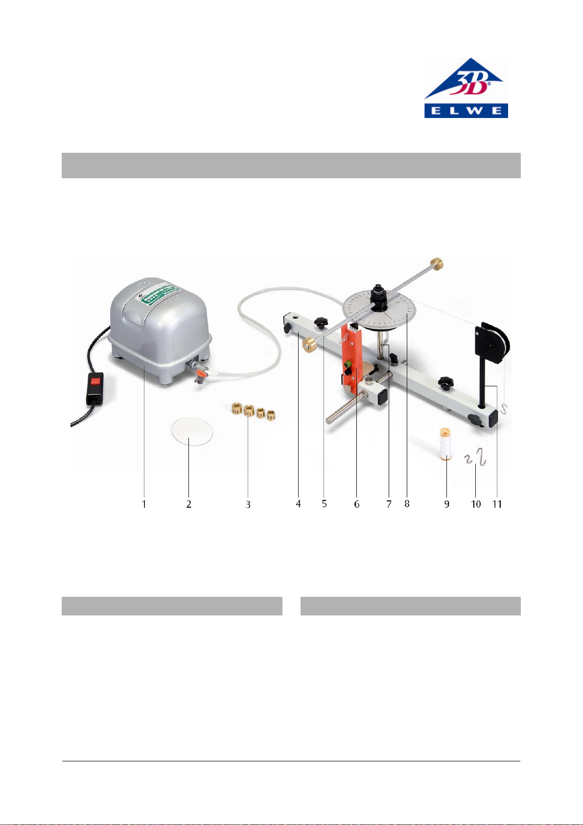
1 Luftstromerzeuger
2 Nivellierscheibe
3 Zusatzmassen
4 Stativrohr, lang
5 Hantelstange
6 Start/Stopp-Einheit
1. Sicherheitshinweise
Das luftgelagerte Drehsystem ist ein empfindliches
Gerätesystem.
• Drehscheibe und Drehlager vor mechanischen
Beschädigungen schützen.
• Das Gerätesystem vor Schmutz, Staub und Flüssig-
keiten schützen.
Bei Verwendung des Laserreflexsensors sind die entsprechenden Vorschriften zum Einsatz von Lasern zu
beachten.
• Nicht in den Laserstrahl blicken.
7 Drehlagereinheit
8 Drehscheibe
9 Garnrolle
10 S-Haken
11 Umlenkrolle
2. Beschreibung
Das luftgelagerte Drehsystem ist ein Gerätesystem zur
Untersuchung reibungsfreier Drehbewegungen zu
folgenden Themen:
Gleichförmige und gleichmäßig beschleunigte Drehbewegungen
Newton’sche Bewegungsgleichungen bei Drehbewegungen
Trägheitsmoment und Drehmoment
Das Gerätesystem eignet sich sowohl zur anschauli-
chen Demonstration, als auch zur Erarbeitung der
1
Page 2

physikalischen Gesetze der Kinematik und Dynamik in
α⋅=
ϕ
⋅
π
=
ϕ
⋅⋅=
s
Schülerübungen und Praktika.
Eine kleine Drehscheibe mit Winkelskala trägt eine
Querstange (Hantelstange) zur Halterung von Massen.
Die Drehscheibe lagert auf einem Luftpolster und
erlaubt so fast reibungsfreie Drehbewegungen, wobei
die Drehachse durch eine Zentrierung vorgegeben ist.
Über eine Umlenkrolle und eine Stufenrolle wird mit
einer Schnur das Gewicht der eingehakten Antriebsmasse übertragen.
Dank der Reibungsarmut reichen sehr geringe Drehmomente zum Auslösen der Drehbewegungen, so dass
der Einfluss der Trägheit der beschleunigenden Masse
auch beim kleinsten Trägheitsmoment des Systems
unter einem Promille liegt. Außerdem können die sich
über mehrere Sekunden erstreckenden Drehbewegungen mühelos mit bloßem Auge und einer Handstoppuhr quantitativ erfasst werden.
Für präzise Messungen ist der Einsatz eines Digitalzählers möglich, der durch die Start/Stopp-Einheit gestartet und bei Nulldurchgang durch das Signal eines
Laserreflexsensors gestoppt wird.
Der Luftstromerzeuger des luftgelagerten Drehsystems
U8405680-115 ist für eine Netzspannung von 115 V
(±10 %) ausgelegt, der im Gerätesystem U8405680-230
für 230 V (±10 %).
Experimente zur Untersuchung von reibungsfreien
Drehschwingungen und zur Untersuchung von reibungsfreien Drehbewegungen mit einer großen Drehscheibe ermöglicht der Ergänzungssatz zum luftgelagerten Drehsystem U8405690.
3. Lieferumfang
1 Drehlagereinheit
1 Drehscheibe mit Hantelstange
1 Stufenrolle
1 Start/Stopp-Einheit
3 S-Haken (2x 1 g, 1x 2g)
1 Satz Zusatzmassen (2x 12,5 g, 2x 25 g, 2x 50 g)
1 Luftstromerzeuger mit Steckernetzgerät
1 Silikonschlauch mit Hahn
1 Umlenkrolle
1 Stativrohr, lang
1 Stativrohr, kurz
1 Stativstange, 250 mm
1 Nivellierscheibe
1 Rolle Nähgarn
4. Technische Daten
Winkelskala: 0 – 360°
Skalenteilung: 1°
Länge der Hantelstange: ca. 440 mm
Radien des Lochrasters: 30 – 210 mm
Schrittweite des Lochrasters: 20 mm
Radien der Stufenrolle: 5 / 10 / 15 mm
Trägheitsmoment der Dreh-
scheibe mit Hantelstange: ca. 0,9 g m
Max. Trägheitsmoment: ca. 7,1 g m
2
2
Min. Antriebsdrehmoment: ca. 0,05 mN m
Max. Antriebsdrehmoment: ca. 0,60 mN m
5. Allgemeine Grundlagen
In Analogie zur Newton’schen Bewegungsgleichung
für Translationsbewegungen gilt: Ein drehbar gelagerter starrer Körper mit dem Trägheitsmoment J erfährt
die Winkelbeschleunigung α, wenn das Drehmoment
(1)
JM .
angreift. Wirkt ein konstantes Drehmoment, so vollzieht der Körper eine Drehbewegung mit gleichmäßiger Winkelbeschleunigung.
Der Körper dreht sich in der Zeit t um den Winkel
1
(2)
2
.
t⋅α⋅=ϕ
2
Daraus folgt für die Winkelbeschleunigung α
(3)
2
t
2
=α
und
=α bei °
(4)
2
t
90
Das Drehmoment M resultiert aus der Gewichtskraft
einer beschleunigenden Masse m
, die im Abstand r
M
M
zur Drehachse am Körper angreift.
gmrM
(5)
m
,g
819
= : Fallbeschleunigung
2
MM
Bringt man auf der Hantelstange des Drehsystems
zusätzlich zwei Massen m
in festem Abstand rJ zur
J
Drehachse an, so vergrößert sich das Trägheitsmoment gemäß
(6)
J
: Trägheitsmoment ohne Zusatzmassen
o
2
0
rmJJ ⋅⋅+=
JJ
2
2
Page 3
6. Bedienung
6.1 Aufbau (siehe Fig. 1 und 2)
• Stativstange (h) mit Stativrohr (f) verbinden und
befestigen.
• Drehlagereinheit (j) auf Stativrohr (f) aufbauen
und Arretierschraube festziehen.
• Umlenkrolle (n) im Stativrohr (f) aufbauen und mit
Arretierschraube befestigen.
• Start/Stopp-Einheit auf Stativrohr (e) aufsetzen,
fixieren und auf Stativstange (h) schieben.
Vor Experimentierbeginn muss das Drehsystem erst
ausgerichtet werden, bevor der weitere Aufbau erfolgen kann.
• Nivellierscheibe in die kreisförmige Vertiefung der
Drehlagereinheit legen.
• Schlauch des Kompressors am Schlauchanschluss
(k) befestigen.
• Kompressor mit dem Netz verbinden und ein-
schalten.
• Mittels der Justierschrauben (g und m) ist eine
Korrektur der Neigung zweier Ebenen möglich
(siehe Fig. 3).
Die Lagekorrektur ist ausreichend, wenn die Nivellierscheibe gleichmäßig über die Fläche des Drehlagers
taumelt.
• Drehscheibe (i) mit Hantelstange und Stufenrolle
auf Drehlagereinheit (j) setzen.
• Start/Stopp-Einheit zur Drehscheibe schieben und
mit Arretierschraube befestigen. Der Schaumstoff
des Zeigers (a) muss den Rand der Drehscheibe
leicht berühren.
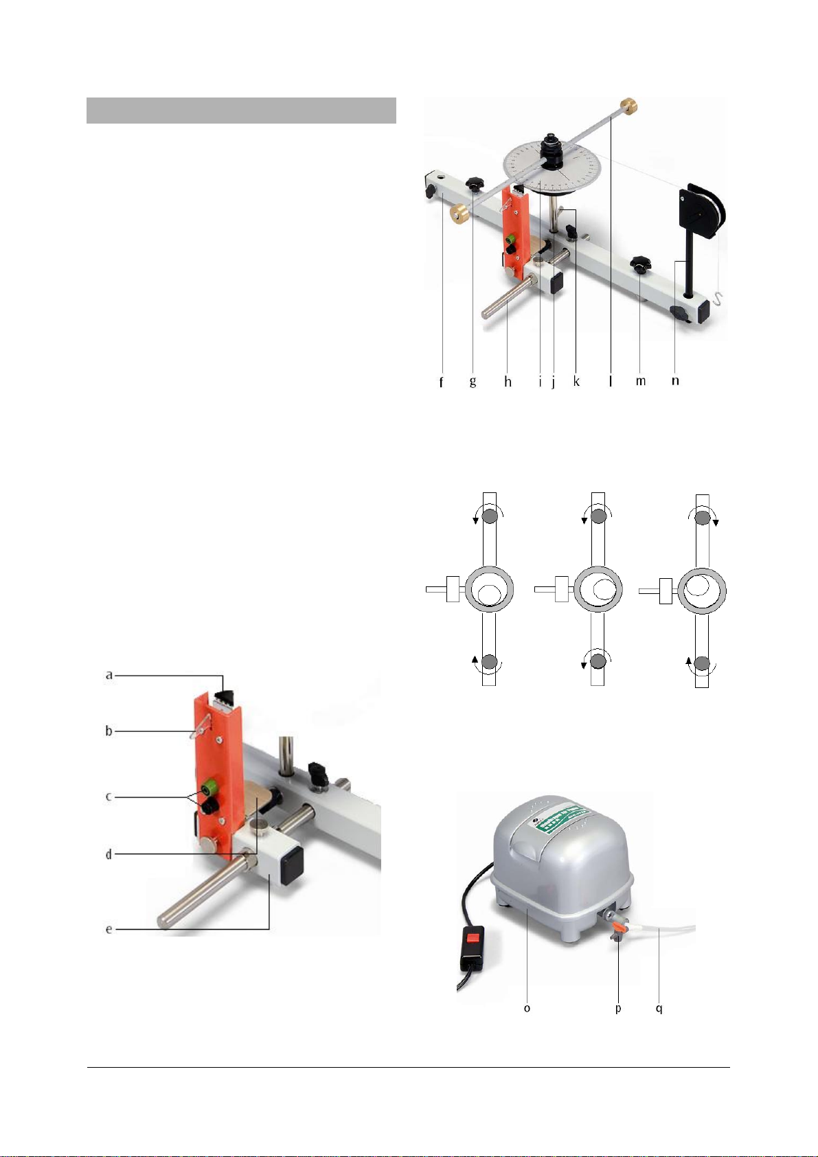
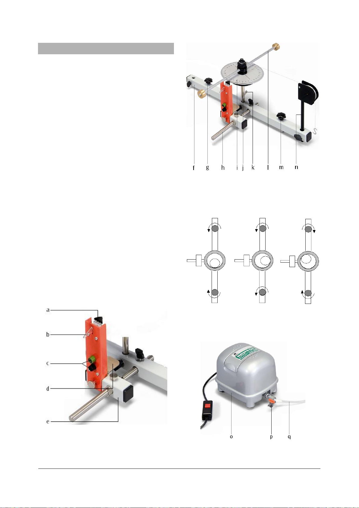
Fig. 2 Aufbau des Drehsystems: f Stativrohr, g Justierschraube, h Stativstange, i Drehscheibe, j Drehlagereinheit, k
Schlauchanschluss, l Hantelstange mit Stufenrolle und Zusatzmassen, m Justierschraube, n Umlenkrolle
Fig. 1 Aufbau der Start/Stopp–Einheit: a Zeiger, b Auslösehebel, c Buchsen für Starter, d Konsole für Laserreflexsensor, d
Stativrohr
Fig. 3 Ausrichtung des Drehsystems
6.2 Regelung der Luftzufuhr
• Luftdurchsatz nur am Hahn (p) regeln.
Fig. 4 Luftzufuhr: o Luftstromerzeuger, p Hahn, q Schlauch
3
Page 4

7. Versuchsbeispiele
Zur Zeitmessung sind folgende Geräte empfehlenswert:
1 Mechanische Stoppuhr U40801
oder
1 Laserreflexsensor U8533380
und
1 Digitalzähler (115 V, 50/60 Hz) U8533341-115
oder
1 Digitalzähler (230 V, 50/60 Hz) U8533341-230
7.1 Gleichmäßig beschleunigte Drehbewegung
7.1.1 Erstellung eines Drehwinkel-Zeit-Diagramms
Empfohlene Parameter:
Beschleunigende Masse m
Stufenrolle r
Zusatzmasse m
= 10 mm
M
= 25 g Abstand rJ = 170 mm
J
= 2 g
M
Drehwinkel ϕ = 10°, 40°, 90°, 160°, 250°
• Zusatzmassen im gleichen Abstand von der Dreh-
achse auf die Hantelstange aufschieben.
• Bindfaden am Metallzapfen der Drehscheibe
befestigen und ca. 5-6 Mal um eine Stufenscheibe
wickeln.
• Das andere Ende des Fadens über die Umlenkrolle
legen und einen der S-Haken daran festknoten.
• Den S-Haken so aufhängen, dass er über eine
Tischkante hängt.
• Drehscheibe in die gewünschte Winkelposition
drehen und mit dem Zeiger arretieren.
• Kompressor einschalten.
• Hebel nach unten drücken und die Drehbewe-
gung auslösen. Gleichzeitig die Zeitmessung mit
der Stoppuhr starten.
• Bei Nulldurchgang (Nullmarke passiert die Positi-
on des Zeigers) Zeitmessung stoppen und abgelesene Zeit notieren.
• Zeiten für verschiedene Drehwinkel bestimmen
und ein t-ϕ-Diagramm erstellen.
Für die empfohlenen Parameter ergeben sich folgende
Zeiten:
10° 40° 90° 160° 250°
2 s 4 s 6 s 8 10 s
7.2 Winkelbeschleunigung in Abhängigkeit des
Drehmoments
Stufenrolle r
Beschleunigende Massen m
• Experimentieraufbau wie unter 6.1 beschrieben.
• Zeiten für den gleichen Drehwinkel mit unter-
schiedlichen beschleunigenden Massen m
= 10 mm
M
= 1 g, 2 g, 3 g, 4 g
M
M
bestimmen und die entsprechende Winkelbeschleunigung α berechnen.
• Abhängigkeit der Winkelbeschleunigung α von der
m
beschleunigenden Masse in einem
M
-α-
Diagramm darstellen.
7.2.2 Winkelbeschleunigung in Abhängigkeit des Stufenrollenradius
Empfohlene Parameter:
Drehwinkel ϕ = 90°
Zusatzmasse m
Beschleunigende Masse m
Stufenrollenradius r
• Experimentieraufbau wie unter 6.1 beschrieben.
• Zeiten für den gleichen Drehwinkel mit unter-
schiedlichen Stufenrollenradien r
= 50 g; Abstand rJ = 210 mm
J
= 2 g
M
= 5 mm, 10 mm, 15 mm
M
bestimmen
M
und die entsprechende Winkelbeschleunigung α
berechnen.
• Abhängigkeit der Winkelbeschleunigung α vom
Radius der Stufenrolle r
in einem rM-α-Diagramm
M
darstellen.
7.3 Winkelbeschleunigung in Abhängigkeit des
Trägheitsmoments
7.3.1 Trägheitsmoment in Abhängigkeit der Zusatzmasse
Empfohlene Parameter:
Drehwinkel ϕ = 90°
Beschleunigende Masse m
Stufenrollenradius r
Zusatzmasse m
Abstand r
• Experimentieraufbau wie unter 6.1 beschrieben.
• Zeiten für den gleichen Drehwinkel mit unter-
= 0 g, 12,5 g, 25 g, 50 g
J
= 210 mm
J
schiedlichen Zusatzmassen m
stand r
bestimmen und das entsprechende Träg-
J
= 2 g
M
= 10 mm
M
bei gleichem Ab-
J
heitsmoment J berechnen.
• Abhängigkeit des Trägheitsmoments J von der
Zusatzmasse m
in einem mJ-J-Diagramm darstel-
J
len.
7.2.1 Winkelbeschleunigung in Abhängigkeit der be-
schleunigenden Masse
Empfohlene Parameter:
Drehwinkel ϕ = 90°
Zusatzmasse m
= 50 g; Abstand rJ = 210 mm
J
7.3.2 Trägheitsmoment in Abhängigkeit des Abstands
der Zusatzmasse von der Drehachse
Empfohlene Parameter:
Drehwinkel ϕ = 90°
Beschleunigende Masse m
= 2 g
M
4
Page 5

Stufenrollenradius rM = 10 mm
Zusatzmasse m
Abstand r
• Experimentieraufbau wie unter 6.1 beschrieben.
• Zeiten für den gleichen Drehwinkel mit unter-
schiedlichen Abständen r
= 50 g
J
= 30 mm, 50 mm, 70 mm, …210 mm
J
der Zusatzmassen
J
bestimmen und das entsprechende Trägheitsmoment J berechnen.
• Abhängigkeit des Trägheitsmoments J vom Ab-
stand r
der Zusatzmassen in einem rJ -J-Diagramm
J
darstellen.
7.4 Zeitmessung mit dem Digitalzähler und dem
Laserreflexsensor
Mit der Start/Stopp-Einheit und dem LaserReflexsensor sind exakte Messungen über definierte
Winkelsegmente möglich (siehe Fig. 1). Durch Betätigen des Hebels (8) erfolgt die mechanische Entriegelung der Drehscheibe und zeitgleich wird ein Schaltkontakt zwischen den Buchsen (6) geöffnet und löst
die Zeitmessung aus. Der Laserreflexsensor ermöglicht
das berührungs- und verzögerungsfreie Stoppen des
Zeitmessvorganges.
Warnhinweis: Nicht in den Laserstrahl blicken!
• Laserreflexsensor auf die Konsole der Start/Stopp-
Einheit stellen (magnetische Befestigung).
• Start/Stopp-Einheit mit dem Start-Eingang und
Laserreflexsensor mit dem Stopp-Eingang am Zähler verbinden.
• Laserreflexsensor so verschieben, dass das Licht
durch die Bohrung der 0°-Position fällt. (Hinweis:
Loch mit einem Papierstreifen abdecken. Laserlicht ist durch Papier gut sichtbar.)
• Drehscheibe in die gewünschte Winkelposition
drehen und mit dem Zeiger bei oberer Hebelstellung arretieren. Dabei berührt der Zeiger nur
leicht den Rand der Drehscheibe.
• Hebel nach unten drücken und so die Drehbewe-
gung und Zeitmessung auslösen.
Die Zeitmessung stoppt, wenn das Licht des Lasers auf
die Bohrung der 0°-Position oder auf eine Marke auf
der Unterseite der großen Drehscheibe (aus dem Ergänzungssatz) trifft.
Elwe Didactic GmbH • Steinfelsstr. 6 • 08248 Klingenthal • Deutschland • www.elwedidactic.com
3B Scientific GmbH • Rudorffweg 8 • 21031 Hamburg • Deutschland • www.3bscientific.com
Technische Änderungen vorbehalten
© Copyright 2008 3B Scientific GmbH
Page 6

Page 7

3B SCIENTIFIC
Rotating System on Air Bed U8405680
Instruction Sheet
04/08 ALF
®
PHYSICS
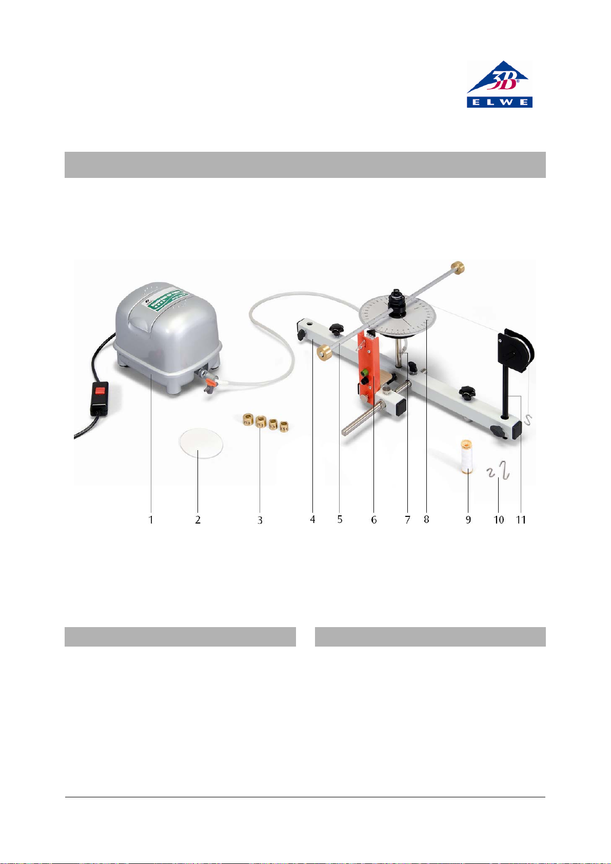
1 Airflow generator (compressor)
2 Levelling washer
3 Additional weights
4 Stand rod, long
5 Transverse beam
6 Start/stop unit
1. Safety Instructions
This rotating system on air bed is a sensitive
instrument.
• Protect the rotating disc and the air bearing from
mechanical damage.
• Protect the system from dirt, dust and liquids.
When using the laser reflection sensor, the
appropriate regulations for the use of lasers must be
observed.
• Do not look into the laser beam.
7 Air-bearing unit
8 Rotating disc
9 Reel of cotton
10 S-hooks
11 Pulley
2. Description
The rotating system on air bed is an instrument for
the study of frictionless rotational motion,
encompassing the following topics:
Steady rotational motion and rotational motion
with uniform acceleration.
Newton’s laws of motion applied to rotational
motion.
Moment of inertia and torque.
The apparatus is suitable both for presenting clear
demonstrations and for students to investigate the
1
Page 8

physical laws of kinematics and dynamics in exercises
α⋅=
ϕ
⋅
π
⋅⋅=
and practical classes.
A small rotating disc marked with an angular scale
supports a transversely mounted beam to which
weights can be attached. The disc rests on an aircushion so that it can rotate virtually without friction
and the axis of rotation is preset by adjusting the
centre. The weight of a driving mass hanging on a
thread is transmitted to the disc via one simple pulley
and a multiple pulley.
Because the frictional drag is minimal, even very small
torques are enough to start the rotational motion.
Consequently, the effect of the inertia contributed by
the accelerating weight on the thread is less than onethousandth of the total, even for the smallest moment
of inertia that an be investigated. Moreover,
measurement of the angular distance covered in a
period of several seconds can be made very easily by
the unaided eye and a hand-operated stopwatch.
For precise measurements it is possible to use a digital
counter, which can be started by the built-in start/stop
unit and stopped by a signal generated when the zero
point of the scale passes through a light beam from a
laser reflection sensor.
The air-flow generator for the rotating apparatus is
designed to operate with a mains voltage of either 230
V ±10 % (U8405680-230) or 115 V ±10 % (U8405680-
115).
A set of accessories is available for the rotating system
on air bed (U8405690) that allows for experiments on
frictionless rotational oscillations and on frictionless
rotational motion with a larger rotating disc.
3. Equipment Supplied
1 Rotational air-cushion bearing unit
1 Rotating disc with transverse beam
1 Multiple pulley
1 Start/stop unit
3 S-shaped hooks (2x 1 g, 1x 2 g)
1 Set of additional weights (2x 12.5 g, 2x 25 g, 2x 50 g)
1 Air-flow generator with mains adapter
1 Silicone-rubber tube with valve
1 Pulley
1 Stand rod, long
1 Stand rod, short
1 Stainless steel rod, 250 mm
1 Levelling washer
1 Reel of cotton-thread
4. Technical Data
Angle scale: 0 – 360°
Scale divisions: 1°
Length of transverse beam: ≈ 440 mm
Radial distance to holes in beam: 30 – 210 mm
Space between holes: 20 mm
Multiple pulley radii: 5/10/15 mm
Moment of inertia of rotating disc
and transverse beam: ≈ 0.9 g m
Max. moment of inertia: ≈ 7.1 g m
2
2
Min. driving torque: ≈ 0.05 mN m
Max. driving torque: ≈ 0.60 mN m
5. Basic Principles
In analogy to Newton’s law of motion for translational
motion, the relationship between the torque M that is
applied to a rigid body with a moment of inertia J,
supported so that it can rotate, and the angular
acceleration
(1)
α
is as follows
JM .
If the applied torque is constant, the body undergoes
a rotational motion with a constant rate of angular
acceleration.
In a time
t from the start, the body rotates through
the following angle:
1
(2)
2
.
t⋅α⋅=ϕ
2
This leads to the following expressions for the angular
α
acceleration
(3)
and, for the special case
(4)
The torque
accelerating mass
:
2
=α
2
t
o
ϕ
= 90
,
=α .
2
t
M results from the weight of an
m
acting at the distance rM from the
M
axis of rotation of the body, and is therefore:
(5)
where
g = 9.81 m/s
gmrM
MM
2
, the gravitational acceleration
constant.
If two additional masses
m
are attached to the
J
transverse beam of the rotating system at a fixed
distance
inertia is increased from the initial value
r
from the axis of rotation, the moment of
J
J
(without
o
added masses) to:
(6)
2
0
rmJJ ⋅⋅+=
JJ
2
2
Page 9
6. Experiment Procedure
6.1 Setting up (see Figs. 1 and 2)
• Attach the stainless steel rod (h) to the long stand
rod (f) and secure it.
• Insert the air-cushion bearing unit (j) in a hole in
the long stand rod (f) and tighten the locking
screw.
• Attach the pulley (n) to a long supporting rod (f)
and secure it with a locking screw.
• Attach the start/stop unit to the short supporting
tube (e), secure it, and slide it onto the stainless
steel rod (h).
Before completing the set-up and beginning the
experiment, the rotating system must be made level.
• Place the levelling disc in the circular recess of the
air-cushion bearing unit.
• Attach the tube from the compressor to the inlet
connector (k).
• Connect the compressor to the mains and switch
it on.
• The two adjustment screws (g and m) allow
inclination with respect to the horizontal to be
adjusted in two planes (see Fig. 3).
The levelling is satisfactory when the levelling disc
spins around evenly over the surface of the air-bearing
unit.
• Place the rotating disc (i), together with the
tranverse and the multiple pulley, on the aircushion bearing unit (j).
• Push the start/stop unit up to the rotating disc
and secure it with the locking screw. The foam
pad of the pointer (a) should be in slight contact
with the edge of the rotating disc.
Fig. 2 Set-up of the rotating system: f long stand rod, g and
m levelling screws, h stainless steel rod,
i rotating disc, j air-cushion bearing unit, k tube inlet,
l transverse beam with graduated pulley and additional
weights, n pulley
Fig. 3 Levelling the rotating system
6.2 Regulating the air supply
• Use only the valve (p) to regulate the airflow.
Fig. 1 Set-up for the start/stop unit: a pointer, b starting
lever, c sockets for starter, d bracket for laser reflection
sensor, e short stand rod
Fig. 4 Air supply controls: o airflow generator (compressor),
p valve, q tube
3
Page 10

7. Sample Experiments
To make time measurements the following
instruments are recommended:
1 Mechanical stopwatch U40801
or
1 Laser reflection sensor U8533380
and
1 Digital counter (230 V, 50/60 Hz) U8533341-230
or
1 Digital counter (115 V, 50/60 Hz) U8533341-115
7.1 Uniformly accelerated rotation
7.1.1 Making a graph of rotation angle versus time
Recommended parameters:
Accelerating mass
Multiple pulley radius
Additional weight
Rotation angles
• Slide the two additional weights onto the
m
= 2 g
M
r
= 10 mm
M
m
= 25 g, distance rJ = 170 mm
J
ϕ = 10°, 40°, 90°, 160°, 250°
transverse beam at the same distance from the
axis of rotation.
• Attach a thread to the metal peg on the rotating
disc and wind about 5-6 turns around a groove of
the multiple pulley.
• Run the other end of the thread over the pulley
and tie one of the S-shaped hooks firmly onto the
end.
• Position the system so that the S-shaped hook
hangs over an edge of the work-bench.
• Turn the rotating disc to the desired angle
position and restrain it with the pointer.
• Switch on the compressor.
• Press the lever down to start the rotation, and
simultaneously start the stopwatch for the time
measurement.
• When the zero mark passes the position of the
pointer, stop the time measurement, read the
time, and write it down.
• Determine the times for different angles of
rotation and plot a
t-
ϕ
diagram.
For the parameters recommended above, the times
are as follows:
10° 40° 90° 160° 250°
2 s 4 s 6 s 8 10 s
7.2 Angular acceleration as a function of torque
m
Additional weight
Multiple pulley radius
Accelerating masses
• Set up the experiment as described under 6.1.
• Determine the times for the same angle of
rotation with different accelerator masses
= 50 g, distance rJ = 210 mm
J
r
= 10 mm
M
m
= 1 g, 2 g, 3 g, 4 g
M
m
and
M
calculate the corresponding angular accelerations
α
.
• Display the dependence of the angular
α
acceleration
on the accelerator mass in an mM-α
diagram.
7.2.2 Angular acceleration with different multiple
pulley radius
Recommended parameters:
Angle of rotation
Additional weight
Accelerating mass
Multiple pulley radii
• Set up the experiment as described under 6.1.
• Determine the times for the same angle of
rotation with differing pulley radii
ϕ
= 90°
m
= 50 g, distance rJ = 210 mm
J
m
= 2 g
M
r
= 5 mm, 10 mm, 15 mm
M
r
and
M
calculate the corresponding angular accelerations
α
.
• Display the dependence of the angular
α
acceleration
r
pulley
on the radius of the multiple
in an rM-α diagram.
M
7.3 Angular acceleration as a function of the
moment of inertia
7.3.1 Moment of inertia as a function of the additional
weight
Recommended parameters:
ϕ
Angle of rotation
Accelerating mass
Multiple pulley radius
Distance
r
= 210 mm
J
Additional weights
• Set up the experiment as described under 6.1.
• Determine the times for the same angle of
rotation with different additional masses
the same distance
corresponding moments of inertia
= 90°
m
= 2 g
M
r
= 10 mm
M
m
= 0 g, 12.5 g, 25 g, 50 g
J
r
, and calculate the
J
m
and
J
J using
Equations 4, 5 and 1.
• Display the dependence of the moment of inertia
J on the additional mass m
in an mJ-J diagram.
J
7.2.1 Angular acceleration with different accelerating
masses
Recommended parameters:
Angle of rotation
ϕ
= 90°
7.3.2 Moment of inertia as a function of the distance
of the additional masses from the axis of rotation
Recommended parameters:
angle of rotation
accelerator mass
ϕ
= 90°
m
M
= 2 g
4
Page 11

graduated pulley radius rM = 10 mm
additional mass
distances
• Set up the experiment as described under 6.1.
• Determine the times for the same angle of
rotation with different distances
m
= 50 g
J
r
= 30 mm, 50 mm, 70 mm, …210 mm
J
r
of the
J
additional mass and calculate the corresponding
moments of inertia
• Display the dependence of the moment of inertia
J on the distance r
J using Equations 4, 5 and 1.
of the additional mass in an rJ-J
J
diagram.
7.4 Time measurements using a digital counter
and the laser reflection sensor
By using the start/stop unit and the laser reflection
sensor, it is possible to make exact measurements
over defined angular segments (see Fig. 1). Operating
the lever (b) releases the brake that is holding the disc,
and simultaneously a switch contact between the two
sockets (c) is opened and starts the time
measurement. A laser reflection sensor can be used to
stop the time measurement at a predetermined
position without touching the disc and without a time
delay.
Warning: do not look into the laser beam!
• Place a laser reflection sensor on the bracket of
the start/stop unit (magnetic holding mechanism).
• Connect the start/stop unit to the counter’s start
signal input and the laser reflection sensor to the
counter’s stop signal input.
• Position the laser reflection sensor so that the
light beam passes through the hole at the 0°
position. (Tip: cover the hole with a strip of paper
– the laser light is easily visible through the
paper.)
• Turn the rotating disc to the desired position on
the scale and hold it there with the pointer by
moving the lever to its upper position. The
pointer should be only in slight contact with the
edge of the disc.
• Press the lever down to start the rotation and the
time measurement.
The time measurement stops when the light from the
laser falls on the hole at the 0° position or on a mark
on the underside of the large rotating disc (including
in the set of additional accessories).
Elwe Didactic GmbH • Steinfelsstr. 6 • 08248 Klingenthal • Germany • www.elwedidactic.com
3B Scientific GmbH • Rudorffweg 8 • 21031 Hamburg • Germany • www.3bscientific.com
Technische Änderungen vorbehalten
© Copyright 2008 3B Scientific GmbH
Page 12

Page 13

3B SCIENTIFIC
Système de rotation sur coussinet d'air U8405680
Instructions d'utilisation
04/08 ALF
®
PHYSICS
1 Générateur de courant d'air
2 Disque de nivellement
3 Masses supplémentaires
4 Tube statif long
5 Barre porte-poids
6 Unité Démarrage/Arrêt
1. Consignes de sécurité
Le système de rotation sur coussin d'air est un
ensemble sensible.
• Protégez la plaque tournante et le coussinet de
pivotement contre des endommagements
mécaniques.
• Protégez l'ensemble contre les saletés, la
poussière et les liquides.
En cas d'utilisation du capteur réflexe laser, observez
les prescriptions d'emploi du laser.
• Ne regardez jamais dans le rayon laser.
7 Unité à coussinet de pivotement
8 Poulie tournante
9 Bobine de fil
10 Crochet en S
11 Poulie de renvoi
2. Description
Le système de rotation sur coussinet d'air est un
ensemble destiné à étudier les mouvements de
rotation sans friction dans les domaines suivants :
Mouvements de rotation uniformes et accélérations
uniformes
Lois de Newton sur les mouvements de rotation
Moment d'inertie et couple de rotation
L'ensemble convient tant à la démonstration qu'à
l'élaboration des lois physiques de la cinématique et
1
Page 14

de la dynamique au cours d'exercices et de travaux
α⋅=
ϕ
⋅
π
=
ϕ
⋅⋅=
s
pratiques réalisés par les élèves.
Une petite poulie tournante à graduation angulaire
porte une barre transversale (barre porte-poids) qui
permet d'accrocher des masses. La poulie repose sur
un coussinet d'air et permet ainsi des mouvements de
rotation pratiquement sans frictions, l'axe de rotation
étant imposé par un dispositif de centrage. Une poulie
de renvoi et une poulie à étages transmettent le poids
de la masse d'entraînement via un cordon.
Grâce aux frictions réduites, il suffit de très faibles
couples de rotation pour déclencher le mouvement de
rotation, de sorte que l'influence de l'inertie de la
masse d'accélération est inférieure à un pour mille,
même si le moment d'inertie du système est minimal.
Par ailleurs, les mouvements de rotation qui durent
plusieurs secondes peuvent être vus à l'œil nu et saisis
quantitativement à l'aide d'un chronomètre
mécanique.
Pour obtenir des mesures précises, on peut aussi
utiliser un compteur numérique qui est lancé par
l'unité Démarrage/Arrêt, puis arrêté par le signal d'un
capteur réflexe laser au moment du passage à zéro.
Le générateur de courant d'air du système de rotation
sur coussinet d'air U8405680-115 est conçu pour une
tension secteur de 115 V (±10 %), celui de l'ensemble
U8405680-230 pour 230 V (±10 %).
Le complément au système de rotation sur coussinet
d'air U8405690 permet d'étudier les oscillations
tournantes sans friction et les mouvements de
rotation sans friction avec une grande poulie
tournante.
3. Matériel fourni
1 unité à coussinet de pivotement
1 poulie tournante avec barre porte-poids
1 poulie à étages
1 unité Démarrage/Arrêt
3 crochets en S (2x 1 g, 1x 2 g)
1 jeu de masses (2x 12,5 g, 2x 25 g, 2x 50 g)
1 générateur de courant d'air avec alimentation
secteur
1 tuyau flexible en silicone avec robinet
1 poulie de renvoi
1 tube statif long
1 tube statif court
1 tige statif, 250 mm
1 disque de nivellement
1 bobine de fil de couture
4. Caractéristiques techniques
Graduation angulaire : 0 – 360°
Division de la graduation : 1°
Longueur de la barre porte-poids : env. 440 mm
Rayons des perforations : 30 – 210 mm
Pas des perforations : 20 mm
Rayons de la poulie à étages : 5 / 10 / 15 mm
Moment d'inertie de la poulie
tournante avec barre porte-poids : env. 0,9 g m²
Moment d'inertie max. : env. 7,1 g m²
Couple d'entraînement min. : env. 0,05 mN m
Couple d'entraînement max. : env. 0,60 mN m
5. Notions de base générales
Par analogie à l'équation de Newton sur les
mouvements de translation, un corps rigide placé sur
un pivot rotatif de moment d'inertie J subit
l'accélération angulaire α, lorsque le couple de
rotation
(1)
JM .
Si le couple de rotation est constant, le corps effectue
un mouvement de rotation à une accélération
angulaire constante.
Le corps tourne pendant le temps t dans un angle
1
(2)
2
.
t⋅α⋅=ϕ
2
Il en résulte pour l'accélération angulaire α
(3)
2
t
2
=α
et
=α avec °
(4)
2
t
90
Le couple de rotation M résulte de la force du poids
d'une masse d'accélération m
dans un écart r
(5)
= : accélération de la pesanteur
avec l'axe de rotation.
M
gmrM
MM
m
,g
819
2
, qui s'attaque au corps
M
Si l'on ajoute à la barre porte-poids du système de
rotation deux masses supplémentaires m
écart fixe r
avec l'axe de rotation, le moment d'inertie
J
dans un
J
augmente selon l'équation
(6)
J
: moment d'inertie sans masses supplémentaires
o
2
0
rmJJ ⋅⋅+=
JJ
2
2
Page 15

6. Manipulation
6.1 Montage (voir fig. 1 et fig. 2)
• Reliez, puis fixez la tige statif (h) au tube statif (f).
• Montez l'unité à coussinet de pivotement (j) sur le
tube statif (f) et serrez-la avec la vis de fixation.
• Montez la poulie de renvoi (n) dans le tube statif
(f) et serrez-la avec la vis de fixation.
• Installez et fixez l'unité Démarrage/Arrêt sur le
tube statif (e), puis glissez-la sur la tige statif (h).
Avant de commencer l'expérience, vous devez d'abord
ajuster le système de rotation.
• Posez le disque de nivellement dans
l'engorgement circulaire de l'unité à coussinet de
pivotement.
• Fixez le tuyau du compresseur au raccordement
(k).
• Reliez le compresseur au secteur et mettez-le en
marche.
• Les vis d'ajustage (g et m) permettent de corriger
l'inclinaison de deux plans (voir la fig. 3).
La correction est suffisante lorsque le disque de
nivellement vacille de manière uniforme au-dessus de
la surface du coussinet de pivotement.
• Placez la poulie tournante (i) avec la barre porte-
poids et la poulie à étages sur l'unité à coussinet
de pivotement (j).
• Glissez l'unité Démarrage/Arrêt vers la poulie
tournante et fixez-la avec la vis de fixation. La
mousse du pointeur (a) doit toucher légèrement le
bord de la poulie tournante.
Fig. 2 Montage du système de rotation : f Tube statif, g Vis
d'ajustage, h Tige statif, i Poulie tournante, j Unité à
coussinet de pivotement, k Raccordement de tuyau, l Barre
porte-poids avec poulie à étages et masses supplémentaires,
m Vis d'ajustage, n Poulie de renvoi
Fig. 1 Montage de l'unité Démarrage/Arrêt : a Pointeur, b
Levier de déclenchement, c Bornes pour starter, d Console
pour capteur réflexe laser, d Tube statif
Fig. 3 Ajustage du système de rotation
6.2 Réglage de l'alimentation d'air
• Ne réglez le débit d'air qu'avec le robinet (p).
Fig. 4 Alimentation d'air : o Générateur de courant d'air, p
Robinet, q Tuyau
3
Page 16

7. Exemples d'expériences
Pour mesurer le temps, le matériel supplémentaire
suivant est recommandé :
1 chronomètre mécanique U40801
ou
1 capteur réflexe laser U8533380
et
1 compteur numérique U8533341-115
ou
1 compteur numérique U8533341-230
7.1 Mouvement de rotation à accélération
uniforme
Angle de rotation ϕ = 90°
Masse supplémentaire m
Poulie à étages r
= 10 mm
M
Masses d'accélération m
• Montez l'expérience comme décrit au paragraphe
= 50 g écart rJ = 210 mm
J
= 1 g, 2 g, 3 g, 4 g
M
6.1.
• Déterminez les temps pour le même angle de
rotation avec différentes masses d'accélération m
M
et calculez l'accélération angulaire
correspondante α.
• Représentez le rapport entre l'accélération
angulaire α et la masse d'accélération dans un
m
diagramme
M
-α.
7.1.1 Réalisation d'un diagramme angle de rotation -
temps
Paramètres recommandés :
Masse d'accélération m
Poulie à étages r
M
Masse supplémentaire m
= 2 g
M
= 10 mm
= 25 g écart rJ = 170 mm
J
Angle de rotation ϕ = 10°, 40°, 90°, 160°, 250°
• Glissez sur la barre porte-poids les masses
supplémentaires qui doivent toutes présenter le
même écart avec l'axe de rotation.
• Fixez le fil de couture au pivot métallique de la
poulie tournante et enroulez-le 5 à 6 fois autour
de la poulie à étages.
• Placez l'autre extrémité du fil sur la poulie de
renvoi et nouez-y l'un des crochets en S.
• Fixez le crochet en S de manière à ce qu'il pende
au-dessus de la table.
• Tournez la poulie tournante dans la position
angulaire souhaitée et fixez-la avec le pointeur.
• Mettez le compresseur en service.
• Appuyez le levier vers le bas et déclenchez le
mouvement de rotation. En même temps, lancez
la mesure du temps avec le chronomètre.
• Lors du passage à zéro (le repère zéro passe sur la
position du pointeur), arrêtez la mesure et notez
le temps indiqué par le chronomètre.
• Déterminez les temps pour différents angles de
rotation et réalisez un diagramme t-ϕ.
Pour les paramètres recommandés, vous obtenez les
temps suivants :
10° 40° 90° 160° 250°
2 s 4 s 6 s 8 10 s
7.2 Accélération angulaire en fonction du couple
de rotation
7.2.1 Accélération angulaire en fonction de la masse
d'accélération
Paramètres recommandés :
7.2.2 Accélération angulaire en fonction du rayon de
la poulie à étages
Paramètres recommandés :
Angle de rotation ϕ = 90°
Masse supplémentaire m
Masse d'accélération m
Rayon de la poulie à étages r
= 50 g écart rJ = 210 mm
J
= 2 g
M
= 5 mm, 10 mm, 15
M
mm
• Montez l'expérience comme décrit au paragraphe
6.1.
• Déterminez les temps pour le même angle de
rotation avec différents rayons de la poulie à
étages r
et calculez l'accélération angulaire
M
correspondante α.
• Représentez le rapport entre l'accélération
angulaire α et le rayon de la poulie à étages r
dans un diagramme r
M
-α.
M
7.3 Accélération angulaire en fonction du moment
d'inertie
7.3.1 Moment d'inertie en fonction de la masse
supplémentaire
Paramètres recommandés :
Angle de rotation ϕ = 90°
Masse d'accélération m
Rayon de la poulie à étages r
Écart r
= 210 mm
J
Masse supplémentaire m
• Montez l'expérience comme décrit au paragraphe
= 2 g
M
= 10 mm
M
= 0 g, 12,5 g, 25 g, 50 g
J
6.1.
• Déterminez les temps pour le même angle de
rotation avec différentes masses supplémentaires
m
et le même écart rJ, puis calculez le moment
J
d'inertie correspondant J.
• Représentez le rapport entre le moment d'inertie
J et la masse supplémentaire m
diagramme
m
-J.
J
dans un
J
4
Page 17

7.3.2 Moment d'inertie en fonction de l'écart de la
masse supplémentaire avec l'axe de rotation
Paramètres recommandés :
Angle de rotation ϕ = 90°
Masse d'accélération m
Rayon de la poulie à étages r
Masse supplémentaire m
Écart r
= 30 mm, 50 mm, 70 mm, …210 mm
J
• Montez l'expérience comme décrit au paragraphe
= 2 g
M
= 50 g
J
= 10 mm
M
6.1.
• Déterminez les temps pour le même angle de
rotation avec différents écarts r
des masses
J
supplémentaires, puis calculez le moment
d'inertie correspondant J.
• Représentez le rapport entre le moment d'inertie
J et l'écart r
diagramme r
des masses supplémentaires dans un
J
-J.
J
7.4 Mesure de temps avec le compteur numérique
et le capteur réflexe laser
L'unité Démarrage/Arrêt et le capteur réflexe laser
permettent des mesures précises sur des segments
angulaires définis (voir fig. 1). Le levier (8) permet le
déverrouillage mécanique de la poulie tournante et,
en même temps, ouvre un contact entre les bornes (6)
et déclenche la mesure de temps. Le capteur réflexe
laser permet un arrêt sans contact ni temporisation de
la mesure.
Avertissement : Ne regardez jamais dans le rayon
laser !
• Placez le capteur réflexe laser sur la console de
l'unité Démarrage/Arrêt (fixation magnétique).
• Reliez l'unité Démarrage/Arrêt à l'entrée de
démarrage et le capteur réflexe laser à l'entrée
d'arrêt du compteur.
• Déplacez le capteur réflexe laser de manière à ce
que la lumière traverse l'alésage de la position 0°.
(Note : recouvrez le trou avec un morceau de
papier. Le rayon laser est bien visible à travers le
papier.)
• Tournez la poulie tournante dans la position
angulaire souhaitée et fixez-la avec le pointeur, le
levier étant en position supérieure. Le pointeur ne
touche que légèrement le bord de la poulie
tournante.
• Appuyez le levier vers le bas et déclenchez ainsi le
mouvement de rotation et la mesure de temps.
La mesure est arrêtée lorsque la lumière du laser
rencontre l'alésage de la position 0° ou un repère sur
la partie inférieure de la grande poulie tournante (sur
le jeu complémentaire).
Elwe Didactic GmbH ▪ Steinfelsstr. 6 ▪ 08248 Klingenthal ▪ Allemagne ▪ www.elwedidactic.com
3B Scientific GmbH ▪ Rudorffweg 8 ▪ 21031 Hamburg ▪ Allemagne ▪ www.3bscientific.com
Sous réserve de modifications techniques
© Copyright 2008 3B Scientific GmbH
Page 18

Page 19
3B SCIENTIFIC
Sistema rotante a sostentamento pneumatico U8405680
Istruzioni per l'uso
04/08 ALF
®
PHYSICS
1 Generatore di corrente d’aria
2 Disco di livellamento
3 Pesi supplementari
4 Tubo di supporto, lungo
5 Asta del manubrio
6 Unità Start/Stop
1. Norme di sicurezza
Il sistema rotante a sostentamento pneumatico è un
sistema sensibile.
• Proteggere il disco rotante e il cuscinetto rotante
da danni meccanici.
• Proteggere il sistema da sporcizia, polvere e
liquidi.
In caso di utilizzo del sensore di riflesso laser devono
essere osservate le disposizioni pertinenti in materia
di utilizzo dei laser.
• Non guardare nel fascio laser.
7 Cuscinetto rotante
8 Disco rotante
9 Rocchetto di filo
10 Gancio S
11 Rullo di rinvio
2. Descrizione
Il sistema rotante a sostentamento pneumatico è un
sistema concepito per l’analisi di movimenti rotatori
senza attrito relativamente ai seguenti temi:
Movimenti rotatori costanti e ad accelerazione
uniforme
Equazioni di moto newtoniane con movimenti rotatori
Momento d'inerzia e momento torcente
Il sistema è idoneo non solo a scopi dimostrativi, ma
anche per la determinazione delle leggi fisiche della
1
Page 20

cinematica e della dinamica in esercitazioni
α⋅=
ϕ
⋅
π
=
ϕ
⋅⋅=
s
scolastiche e pratiche.
Un piccolo disco rotante con scala angolare sostiene
un'asta trasversale (manubrio) per il supporto di pesi.
Il disco rotante poggia su un cuscino d’aria e pertanto
consente movimenti rotatori praticamente in assenza
di attrito, in quanto l’asse di rotazione è preimpostato
mediante un centraggio. Il peso della massa di
azionamento agganciata ad una corda viene
trasmesso tramite una puleggia e un rullo graduato.
Grazie all’attrito molto scarso bastano momenti
torcenti molto bassi per attivare i movimenti rotatori,
cosicché l’influenza dell’inerzia della massa in
accelerazione rimane anche con momenti d’inerzia
minimi del sistema al disotto di valori millesimali. I
movimenti rotatori che si protraggono per parecchi
secondi possono essere facilmente rilevati anche ad
occhio nudo e con un cronometro manuale.
Per misurazioni di precisione è possibile utilizzare un
contatore digitale che viene attivato dall’unità di
Start/Stop e si arresta al passaggio attraverso lo zero
del segnale di un sensore di riflesso laser.
Il generatore di corrente d’aria del sistema rotante a
sostentamento pneumatico U8405680-115 è
predisposto per una tensione di rete di 115 V (±10 %),
mentre quello del sistema U8405680-230 è
predisposto per una tensione di 230 V (±10 %).
Il set supplementare per sistema rotante a
sostentamento pneumatico U 8405690 consente la
conduzione di esperimenti per l'analisi di oscillazioni
di torsione e movimenti rotatori senza attrito con un
disco rotante di grandi dimensioni.
3. Fornitura
1 unità con disco rotante
1 disco rotante con asta del manubrio
1 rullo graduato
1 unità Start/Stop
3 ganci ad S (2x 1 g, 1x 2g)
1 set di pesi (2x 12,5 g, 2x 25 g, 2x 50 g)
1 generatore di corrente d’aria con alimentatore ad
innesto
1 tubo di silicone con rubinetto
1 puleggia
1 tubo di supporto, lungo
1 tubo di supporto, corto
1 asta di sostegno, 250 mm
1 disco di livellamento
1 rocchetto di filo da cucire
4. Dati tecnici
Scala angolare: 0 – 360°
Divisione scala: 1°
Lunghezza dell'asta del manubrio: ca. 440 mm
Raggi della guida forata: 30 – 210 mm
Ampiezza della guida forata: 20 mm
Raggi del rullo graduato: 5 / 10 / 15 mm
Momento d’inerzia del disco
rotante con asta manubrio: ca. 0,9 g/m
Momento d’inerzia max.: ca. 7,1 g/m
2
2
Momento torcente min.: ca. 0,05 mN/m
Momento torcente max.: ca. 0,60 mN/m
5. Basi generali
Analogamente all’equazione del moto newtoniana
relativa ai movimenti di traslazione si può affermare:
un corpo rigido montato in modo girevole con un
momento d’inerzia J è soggetto ad un’accelerazione
angolare α, quando il momento torcente
(1)
JM .
viene applicato. Se agisce un momento torcente
costante, il corpo compie un movimento rotatorio con
un’accelerazione angolare uniforme.
Il corpo ruota nel tempo t intorno all’angolo
1
(2)
2
.
t⋅α⋅=ϕ
2
Ne consegue quindi che per l’accelerazione angolare
α
(3)
2
t
2
=α
e
°
(4)
=α con
2
t
90
Il momento torcente M risulta dalla rotazione della
forza peso di una massa in accelerazione m
interviene alla distanza r
rispetto all’asse di rotazione
M
, che
M
del corpo.
(5)
m
,g =
819
gmrM
MM
: Accelerazione di caduta
2
Se sull’asta a manubrio del sistema rotante si
applicano altre due masse m
ad una distanza fissa rJ
J
rispetto all’asse di rotazione, il momento d’inerzia
aumenta secondo
(6)
J
: Momento d’inerzia senza aggiunta di masse
o
2
0
rmJJ ⋅⋅+=
JJ
2
2
Page 21

6. Utilizzo
6.1 Montaggio (ved. Fig. 1 e 2)
• Collegare e fissare l’asta di supporto (h) al tubo di
supporto (f).
• Montare il cuscinetto rotante (j) sul tubo di
supporto (f) e serrare la vite di fermo.
• Montare il rullo di rinvio (n) nel tubo di supporto
(f) e fissare con la vite di fermo.
• Applicare l’unità di Start/Stop sul tubo di supporto
(e), fissare e far scorrere sull’asta di supporto (h).
Prima di iniziare l’esperimento è necessario orientare
innanzitutto il sistema rotante per poi poter
proseguire con le operazioni di montaggio.
• Collocare il disco di livellamento nell’incavo a
forma circolare del cuscinetto rotante.
• Fissare il tubo del compressore al rispettivo
attacco (k).
• Collegare il compressore alla rete ed accendere.
• Con le viti di registro (g e m) è possibile praticare
una correzione dell’inclinazione dei due piani
(ved. Fig. 3).
La correzione di posizione è sufficiente quando il
disco di livellamento oscilla regolarmente sulla
superficie del cuscinetto rotante.
• Posizionare il disco rotante (i) con asta manubrio
e rullo graduato sul cuscinetto rotante (j).
• Far scivolare l’unità Start/Stop verso il disco
rotante e fissare con la vite di fermo. L’espanso
dell’indicatore (a) deve sfiorare il margine del
disco rotante.
Fig. 2 Struttura del sistema rotante: f Tubo di supporto, g
Vite di registro, h Asta di supporto, i Disco rotante, j
Cuscinetto rotante, k Attacco tubo, l Asta manubrio con rullo
graduato e pesi supplementari, m Vite di registro, n Puleggia
Fig. 1 Montaggio dell’unità Start/Stop: a Indicatore, b Leva di
sgancio, c Jack per lo starter, d Console per sensore di
riflesso laser, d Tubo di supporto
Fig. 3 Allineamento del sistema rotante
6.2 Regolazione dell’apporto d’aria
• Regolare la portata dell’aria solo sul rubinetto (p).
Fig. 4 Apporto d’aria: o Generatore di corrente d’aria, p
Rubinetto, q Tubo
3
Page 22

7. Esempi di esperimenti
Per misurare il tempo si consiglia di utilizzare gli
apparecchi seguenti:
1 cronometro meccanico U40801
oppure
1 sensore di riflessione laser U8533380
e
1 Contatore digitale (1 V, 50/60 Hz) U8533341-115
oppure
1 Contatore digitale (230 V, 50/60 Hz) U8533341-230
7.1 Movimenti rotatori ad accelerazione costante
Angolo di rotazione ϕ = 90°
Massa aggiuntiva m
Rullo graduato r
Masse in accelerazione m
• Struttura sperimentale come descritta al punto
= 50 g distanza rJ = 210 mm
J
= 10 mm
M
= 1 g, 2 g, 3 g, 4 g
M
6,1.
• Determinare i tempi dello stesso angolo di
rotazione con masse diverse in accelerazione m
M
e calcolare la rispettiva accelerazione angolare α.
• Rappresentare la relazione tra l’accelerazione
angolare α e la massa in accelerazione con un
m
diagramma
M
-α.
7.1.1 Realizzazione di un diagramma angolo di
rotazione-tempo
Parametri consigliati:
Massa in accelerazione m
Rullo graduato r
= 10 mm
M
Massa aggiuntiva m
= 2 g
M
= 25 g distanza rJ = 170 mm
J
Angoli di rotazione ϕ = 10°, 40°, 90°, 160°, 250°
• Infilare sull’asta del manubrio i pesi aggiuntivi ad
una distanza uguale dall’asse di rotazione.
• Fissare il filo al perno di metallo del disco rotante
ed avvolgerlo 5-6 volte intorno ad un disco
graduato.
• Mettere l’altra estremità del filo sulla puleggia e
annodarla ad uno dei ganci ad S.
• Appendere il gancio ad S in modo che penda su
uno degli angoli del tavolo.
• Girare il disco rotante nella posizione angolare
desiderata e bloccarlo con l’indicatore.
• Avviare il compressore.
• Spingere la leva verso il basso ed attivare il
movimento rotatorio. Avviare
contemporaneamente la misurazione del tempo
con il cronometro.
• Al passaggio attraverso lo zero (lo zero supera la
posizione dell’indicatore) fermare la misurazione
del tempo ed annotare il tempo rilevato.
• Definire i tempi di diversi angoli di rotazione e
realizzare un diagramma t-ϕ.
Per i parametri consigliati si ottengono i seguenti
tempi:
10° 40° 90° 160° 250°
2 s 4 s 6 s 8 10 s
7.2 Accelerazione angolare in funzione del
momento torcente
7.2.1 Accelerazione angolare in funzione della massa
in accelerazione
Parametri consigliati:
7.2.2 Accelerazione angolare in funzione del raggio
del rullo graduato
Parametri consigliati:
Angolo di rotazione ϕ = 90°
Massa aggiuntivo m
Masse in accelerazione m
Raggio del rullo graduato r
• Struttura sperimentale come descritta al punto
= 50 g distanza rJ = 210 mm
J
= 2 g
M
= 5 mm, 10 mm, 15 mm
M
6,1.
• Determinare i tempi dello stesso angolo di
rotazione con raggi diversi del rullo graduato r
e
M
calcolare la rispettiva accelerazione angolare α.
• Rappresentare la relazione tra l’accelerazione
angolare α e il raggio del rullo graduato r
diagramma r
M
-α.
con un
M
7.3 Accelerazione angolare in funzione del
momento d’inerzia
7.3.1 Momento d’inerzia in funzione del peso
aggiuntivo
Parametri consigliati:
Angolo di rotazione ϕ = 90°
Masse in accelerazione m
Raggio del rullo graduato r
Distanza r
= 210 mm
J
Massa aggiuntiva m
• Struttura sperimentale come descritta al punto
= 2 g
M
= 10 mm
M
= 0 g, 12,5 g, 25 g, 50 g
J
6,1.
• Determinare i tempi per lo stesso angolo di
rotazione con masse aggiuntive diversi m
distanza uguale r
e calcolare il rispettivo
J
ad una
J
momento d’inerzia J.
• Rappresentare la relazione tra il momento
d’inerzia J e la massa aggiuntiva m
diagramma
m
-J.
J
con un
J
7.3.2 Momento d’inerzia in funzione della distanza del
peso aggiuntivo dall’asse di rotazione
Parametri consigliati:
4
Page 23

Angolo di rotazione ϕ = 90°
Peso in accelerazione m
Raggio del rullo graduato r
Massa aggiuntiva m
Distanza r
• Struttura sperimentale come descritta al punto
= 30 mm, 50 mm, 70 mm, …210 mm
J
= 2 g
M
= 50 g
J
= 10 mm
M
6,1.
• Determinare i tempi per lo stesso angolo di
rotazione con distanze r
diverse delle masse
J
aggiuntive e calcolare il rispettivo momento
d’inerzia J.
• Rappresentare la relazione tra il momento
d’inerzia J e la distanza r
con un diagramma m
delle masse aggiuntive
J
-J.
J
7.4 Misurazione del tempo con contatore digitale e
sensore di riflesso laser
Con l’unità Start/Stop ed il sensore di riflesso laser si
possono eseguire misurazioni esatte di segmenti
angolari definiti (ved. Fig. 1). Azionando la leva (8) si
ottiene lo sblocco meccanico del disco rotante con
contemporanea apertura di un contatto di
commutazione tra jack (6) ed inserimento della
misurazione del tempo. Il sensore di riflesso laser
consente un bloccaggio senza contatto e senza ritardi
del processo di misurazione del tempo.
Avvertenza: Non guardare nel fascio laser.
• Posizionare il sensore di riflesso laser sulla
console dell’unità Start/Stop (fissaggio magnetico).
• Collegare l’unità Start/Stop con l’ingresso Start ed
il sensore di riflesso laser all’ingresso Stop del
contatore.
• Spostare il sensore di riflesso laser in modo che la
luce passi attraverso il foro della posizione 0°.
(Nota: coprire il foro con una striscia di carta. La
luce laser è ben visibile attraverso la carta.)
• Girare il disco rotante nella posizione angolare
desiderata e bloccarlo con l’indicatore nella
posizione superiore della leva. L’indicatore
sfiorerà appena il margine del disco rotante.
• Spingere la leva verso il basso ed inserire il
movimento rotatorio e la misurazione del tempo.
La misurazione del tempo si arresta, quando la luce
del laser arriva sul foro della posizione 0°o su un
contrassegno presente sul lato inferiore del disco
rotante grande (del kit aggiuntivo).
Elwe Didactic GmbH • Steinfelsstr. 6 • 08248 Klingenthal • Germania • www.elwedidactic.com
3B Scientific GmbH • Rudorffweg 8 • 21031 Amburgo • Germania • www.3bscientific.com
Con riserva di modifiche tecniche
© Copyright 2008 3B Scientific GmbH
Page 24

Page 25

3B SCIENTIFIC® PHYSICS
Sistema giratorio sobre cojín neumático U8405680
Instrucciones de uso
04/08 ALF
1 Generador de corriente de aire
2 Disco de nivelación
3 Masas adicionales
4 Tubo soporte, largo
5 Varilla transversal de haltera
6 Unidad de Marcha/Parada
1. Advertencias de seguridad
El sistema giratorio sobre cojín neumático es un
sistema de aparatos de alta sensibilidad.
• Proteja el disco giratorio y el soporte giratorio
contra daños mecánicos.
• Proteja en sistema de aparatos contra
contaminaciones, polvo y líquidos.
Al utilizar un sensor de refexión de laser de deben
tener en cuenta las prescripciones referentes al uso de
un laser.
• Nunca se debe mirar directamente en el rayo del
Láser.
7 Unidad de soporte giratorio
8 Disco giratorio
9 Garnrolle
10 Ganchos en S
11 Polea de desviación
2. Descripción
El sistema giratorio sobre cojín neumático es un
sistema de aparatos para el estudio de movimientos
de rotación libres de fricción sobre lo sobre los
siguientes temas:
Movimientos de rotación uniforme y uniformemente
acelerado
Ecuaciones de movimento de Newton para el
movimiento de rotación
Momento de inercia y par de fuerzas
El sistema de aparatos es apropiado tanto para la
demostrar claramente y estudiar detalladamente las
1
Page 26

α⋅=
ϕ
⋅
π
=
ϕ
⋅⋅=
s
leyes físicas de la cinemática y la dinámica del
movimiento de rotación, por medio de experimentos
de alumnos y en laboratorios de prácticas.
Un disco giratorio pequeño lleva una varilla transversal (varilla de haltera) para el soporte de masas. El
disco giratorio se encuentra sobre un cojín de
neumático y permite así movimientos de rotación,
casi libres de fricción, pasando el eje de rotación por
medio de una unidad de centrado prevista. Usando
una polea escalonada, una de desviación y una cuerda
se transmite como fuerza el peso de la masa de
accionamiento enganchada.
Gracias a la fricción tan reducida, bastan pares de
fuerza mínimos para generar un movimiento de
rotación así que la influencia de la inercia de la masa
que acelera está por debajo del uno por mil, también
en los casos de momentos de inercia mínimos del
sistema. Además movimientos de rotación que se
extiendan por más de varios segundos se pueden
estudiar cuantitativamente sólo con la vista y con un
cronómetro de mano.
Para mediciones más precisas se recomienda el
empleo de un contador digital, el cual se pone en
marcha por la unidad de Marcha/Parada la que al
paso por cero se deja detener por medio de la señal
de un sensor de reflexión de Láser.
El generador de corriente de aire del sistema sobre
cojín neumático U8405680-115 está diseñado para
una tensión de red de 115 V (±10 %); el del sistema de
aparatos U8405680-230 corres-pondientemente para
230 V (±10 %).
Experimentos para el estudio de oscilaciones
angulares y de movimientos de rotación ambos, con
fricción reducida, se hacen posibles con el juego de
aparatos adicional del sistema giratorio sobre cojín
neumático U8405690.
3. Volumen de entrega
1 Unidad de soporte giratorio
1 Disco giratorio con varilla transversal de haltera
1 Polea escalonada
1 Unidad de Marcha/Parada
3 Ganchos en S (2x 1 g, 1x 2g)
1 Masas adicionales (2x 12,5 g, 2x 25 g, 2x 50 g)
1 Generador de corriente de aire con fuente de ali-
mentación enchufable
1 Manguera de silicona con llave
1 Polea de desviación
1 Tubo soporte, largo
1 Tubo soporte, corto
1 Varilla soporte
1 Disco de nivelación
1 Carrete de hilo de coser
4. Datos técnicos
Escala angular: 0 – 360°
Divisiones de escala: 1°
Longitud de la varilla transversal: aprox. 440 mm
Radios de la retícula de huecos: 30 – 210 mm
Pasos de la retícula de huecos: 20 mm
Radios de la polea escalonada: 5 / 10 / 15 mm
Momento de inercia del disco
giratorio con la varilla transversal: aprox. 0,9 g m
Momento de inercia max.: aprox. 7,1 g m
2
2
Par de fuerzas de
accionamiento min.: aprox. 0,05 mN m
Par de fuerzas de
accionamiento max: aprox. 0,60 mN m
5. Fundamentos generales
En analogía con las ecuaciones de Newton para el
movimiento de translación se establece: Un cuerpo
rígido con un momento de inercia J ,colocado en tal
forma que pueda girar, experimenta una aceleración
angular α cuando el par de fuerzas M actúa sobre él,
se tiene la relación:
(1)
JM
.
Si sobre el cuerpo rígido actúa un par de fuerzas
constante, éste realiza un movimiento de rotación con
aceleración angular constante.
En el tiempo t el cuerpo rota un ángulo igual:
1
2
(2)
t⋅α⋅=ϕ
2
.
A partir de esta relación se obtiene la aceleración
angular α
(3)
2
t
2
=α
y
°
(4)
=α
con
2
t
90
El par de fuerzas M se origina por la fuerza originada
por el peso de la masa m
a una distancia r
(5)
,g
819
=
del eje de rotación.
M
MM
m
: Aceleración de caída libre
2
Se fijan adicionalmente dos masas m
haltera a una distancia fija r
, que actúa sobre el cuerpo
M
gmrM
en la vari lla de
con respecto al eje de
J
J
rotación, el momento de inercia del sistema se
aumenta de acuerdo con:
(6)
J
: Momento de inercia sin las masas adicionales
o
2
0
2
rmJJ ⋅⋅+=
JJ
2
Page 27

6. Manejo
6.1 Montaje (ver Figs. 1 y 2)
• Se conecta y se fija la varilla soporte (h) con el
tubo soporte (f).
• La unidad de soporte giratorio (j) se monta sobre
el tubo soporte (f) y se aprieta el tornillo de enclavamiento.
• Se monta la polea de desviación (n) en el tubo
soporte (f) y se fija con el tornillo de enclavamiento.
• Se coloca la unidad de Marcha/Parada sobre el
tubo soporte (e), se fija y se desplaza so bre la varilla soporte (h).
Antes de iniciar el experimento se debe orientar el
sistema giratorio y también antes de poder continuar
con el montaje siguiente.
• Se coloca el disco de nivelación en la depresión
redonda de la unidad de soporte giratorio.
• Se fija la manguera del compresor en el empalme
de manguera (k).
• Se conecta al compresor a la red y se pone en
marcha.
• Con los tornillos de ajuste (g y m) es posible
realizar una corrección de la inclinación en dos
planos (ver Fig. 3).
La corrección de la posición es suficiente cuando el
disco de nivelación bambolea uniformemente sobre la
superficie del soporte giratorio .
• El disco giratorio (i) junto con la varilla de haltera
y la polea escalonada se coloca sobre la unidad de
soporte giratorio (j).
• Se desliza la unidad de Marcha/Parada hacia el
disco giratorio y se fija con un tornillo de enclavamiento. La gomaespuma del índice (a) debe rozar muy levemente el borde del disco giratorio.
Fig. 2 Montaje del sistema giratorio: (f) Tubo soporte, (g)
Tornillo de ajuste, (h) Varilla soporte, (i) Disco giratorio, (j)
Unidad de soporte giratorio, (k) Empalme de manguera, (l)
Varilla de haltera con polea escalonada y masas adicionales,
(m) Torni llo de ajuste, (n) Polea de desviación
Fig. 3 Orientación del sistema giratorio
6.2 Regulación de la entrada de aire
• El caudal de aire se regula sólo con la llave (p).
Fig. 1 Montaje de la unidad Marcha/Parada: (a) Índice, (b)
Palanca de liberación, (c) Casquillos para el arranque, (d)
Consola para el sensor de reflexión de Láser, (e) Tubo
soporte
Fig. 4 Entrada de aire: (o) Generador de corriente de aire, (p)
Llave, (q) Manguera
3
Page 28

7. Ejemplos de experimentación
Para la medición de los tiempos se recomiendan los
siguientes aparatos:
1 Cronómetro mecánico U40801
o
1 Sensor de reflexión de Láser U8533380
y
1 Contador digital (115 V, 50/60 Hz) U8533341-115
o
1 Contador digital (230 V, 50/60 Hz) U8533341-230
7.1 Movimiento de rotación uniformemente acele-
rado
7.1.1 Elaboración de un diagrama Ángulo de rotación
- Tiempo
Parámetros recomendados:
Masa de aceleración m
Polea escalonada r
Masa adicional m
= 2 g
M
= 10 mm
M
= 25 g; Distancia rJ = 170 mm
J
Ángulo de rotación ϕ = 10°, 40°, 90°, 160°, 250°
• Deslizar las masas adicionales sobre la varilla de
haltera a la misma distancia a uno y otro lado del
eje de rotación.
• Se fija el hilo de coser en la espiga metálica del
disco giratorio y se enrolla unas 5 ó 6 veces en un
disco escalón de la polea escalonada.
• El otro extremo del hilo se hace pasar sobre la
polea de desviación y se hija con un nudo uno de
los ganchos en S.
• El gancho en S se cuelga que quede más allá del
borde de la mesa.
• Se gira el disco giratorio a la posición angular
deseada y se enclava con el índice.
• Se pone en marcha el compresor.
• Se presiona hacia abajo la palanca para ini ciar el
movimiento de rotación. Al mismo tiempo se pone en marcha la medición del tiempo con el cronómetro.
• Al paso por cero (Marca “cero“ de la posición del
índice) se detiene la medición del tiempo: Se lee y
se anota el tiempo medido.
• Se determinan los tiempos para diferentes
ángulos de rotación y se elabora un diagrama t-ϕ.
Con los parámetros recomendados se obtienen los
siguientes tiempos:
10° 40° 90° 160° 250°
2 s 4 s 6 s 8 10 s
7.2 Aceleración angular en dependencia con el par
de fuerzas
7.2.1 Aceleración angular en dependencia con la masa
de aceleración
Parámetros recomendados:
Ángulo de rotación ϕ = 90°
Masa adicional m
Polea escalonada r
Masas de aceleración m
• Montaje experimental como se describe en el
= 50 g; Distancia rJ = 210 mm
J
= 10 mm
M
= 1 g, 2 g, 3 g, 4 g
M
punto 6.1.
• Se determinan los tiempos para el mismo ángulo
de rotación con diferentes masas de
accionamiento m
y se calcula la correspondiente
M
aceleración angular α.
• Representar la dependencia de la aceleración
angular α con la masa de aceleración en un di-
m
agrama
M
-α.
7.2.2 Aceleración angular en dependencia con el radio
de la polea escalonada.
Parámetros recomendados:
Ángulo de rotación ϕ = 90°
Masa adicional m
Masa de aceleración m
Radio de la polea escalonada r
= 50 g; Distancia rJ = 210 mm
J
= 2 g
M
= 5 mm, 10 mm, 15
M
mm
• Montaje experimental como se describe en el
punto 6.1.
• Se determinan los tiempos para el mismo ángulo
de rotación con diferentes radios de la polea
escalonada r
y se calcula la corres pondiente
M
aceleración angular α .
• Se representa en un diagrama r
-α la dependen-
M
cia de la aceleración angular α con el radio de la
polea r
.
M
7.3 Aceleración angular en dependencia con el
momento de inercia
7.3.1 Momento de inercia en dependencia con la las
masas adicionales
Parámetros recomendados:
Ángulo ϕ = 90°
Masa de aceleración m
Radio de la polea escalonada r
Masas adicionales m
Distancia r
• Montaje experimental como se describe en el
= 210 mm
J
= 2 g
M
= 10 mm
M
= 0 g, 12,5 g, 25 g, 50 g
J
punto 6.1.
• Se determinan los tiempos para el mismo ángulo
de rotación con diferentes masas adicionales con
4
Page 29

la misma distancia rJ y se calcula el
correspondiente momento de inercia J .
• Se representa la en un diagrama m
-J la depen-
J
dencia del momento de inercia J con la masa adicional m
.
J
7.3.2 Momento de inercia en dependencia con la
distancia de las masas adicionales con respecto al eje
de rotación
Parámetros recomendados:
Ángulo de rotación ϕ = 90°
Masa de aceleración m
Radio del escalón de la polea r
Masa adicional m
Distancia r
• Montaje experimental como se describe en el
= 30 mm, 50 mm, 70 mm, …210 mm
J
M
= 50 g
J
= 2 g
= 10 mm
M
punto 6.1.
• Se determinan los tiempos para el mismo ángulo
de rotación con diferentes distancias r
de las
J
masa adicionales y se calcula el corres pondiente
momento de inercia J .
• Se representa en un diagrama r
del momento de inercia J con la dis tancia r
-J la dependencia
J
de las
J
masas adicionales .
7.4 Medición de tiempos con el contador digital y
el sensor de reflexión de Láser
Con la unidad de Marcha/Parada y el sensor de
reflexión de Láser es posible realizar mediciones
exactas con un segmento angular definido (ver Fig. 1).
Accionando la palanca (8) se realiza el desbloqueo
mecánico del disco giratorio y al mismo tiempo se
abre un contacto de mando entre los casquillos (6)
iniciando así la medición del tiempo. El sensor de
reflexión de Láser hace posible detención del proceso
de medición de tiempos sin contacto directo y libre de
retardo.
Advertencia: ¡Nunca se debe mirar directamente en
el rayo de Láser!
• Se coloca el sensor de reflexión de Láser sobre la
consola de la unidad de Marcha/Parada (fijación
magnética).
• La unidad de Marcha/Parada se conecta con la
entrada “Start“ del sensor de reflexión de Láser y
con la entrada “Stop“ del contador.
• El sensor de reflexión de Láser se desplaza de tal
forma que la luz pase por el orificio 0°.
(Observación: El orificio se tapa con una banda de
papel. La luz del Láser se puede observar bien a
través del papel.)
• El disco giratorio se gira a la posición angular
deseada y se enclava con índice, estando la
posición de la palanca hacia arriba. En este caso
el índice el índice roza muy levemente el borde
del disco giratorio.
• Se presiona la palanca hacia abajo de tal forma
que se disparen al mismo tiempo el movimiento
de rotación y la medición del tiempo.
La medición del tiempo se detiene cuando la luz del
Láser incide sobre la posición 0° o sobre una marca en
la parte inferior del disco giratorio grande (del juego
de aparatos adicional).
Elwe Didactic GmbH ▪ Steinfelsstr. 6 ▪ 08248 Klingenthal ▪ Alemania ▪ www.elwedidactic.com
3B Scientific GmbH ▪ Rudorffweg 8 ▪ 21031 Hamburgo ▪ Alemania ▪ www.3bscientific.com
Se reservan las modificaciones técnicas
© Copyright 2007 3B Scientific GmbH
Page 30

Page 31

3B SCIENTIFIC
Sistema rotativo sustentado por ar U8405680
Instrução de operação
04/08 ALF
®
PHYSICS
1 Gerador de fluxo de ar
2 Disco nivelador
3 Massas suplementares
4 Tubo suporte, comprido
5 Barra transversal
6 Unidade Start/Stop
1. Notas de segurança
O sistema rotatório sustentado por ar é um sistema de
aparelhos sensíveis.
• Proteger o disco rotatório e o mancal rotatório
contra danos mecânicos.
• Proteger o sistema de aparelhos contra sujeira e
líquidos.
Para utilização do sensor de reflexo Laser, atenção
para as prescrições de uso de Lasers
• Não olhar diretamente para o raio Laser.
7 Unidade de mancal rotativo
8 Disco rotativo
9 Carretel de linha
10 Ganchos S
11 Roldana de desvio
2. Descrição
O sistema rotatório sobre mancal de ar é um sistema
de aparelhos para examinar movimentos rotatórios
isentos de atrito para os seguintes temas:
Movimentos rotatórios ativos uniformes e acelerados
uniformemente
Equações de movimentos de Newton para
movimentos rotatórios
Momento de inércia e momento de torque
O sistema de aparelhos é adequado tanto para
demonstrações visuais como para a prática das leis
1
Page 32

físicas da cinemática e dinâmica em ensaios de
α⋅=
ϕ
⋅
π
=
ϕ
⋅⋅=
s
estudantes e estágios.
Um pequeno disco giratório com escala angular
suporta uma barra transversal (barra de suporte) para
fixação de massas. A placa rotativa é apoiada numa
almofada de ar e permite assim movimentos rotativos
quase isentos de atrito, sendo que o eixo de rotação é
determinado por uma centralização. Através de uma
roldana de desvio e uma roldana escalonada o peso
da massa de acionamento enganchada é transmitido
com um fio/barbante.
Graças ao atrito insignificante são suficientes
momentos de giro reduzidíssimos para desencadear
os movimentos rotativos, de modo que a influência da
inércia da massa acelerada mesmo mediante o
momento de inércia mínimo do sistema fique abaixo
de um milésimo. Além disso os movimentos rotatórios
remanescentes por vários segundos podem ser
registrados quantitativamente a olho nu e com um
cronômetro sem qualquer esforço.
Para medições precisas é possível utilizar o contador
digital que pode ser ativado pela unidade Start/Stop e
ser parado pelo sinal de um sensor de reflexo Laser
mediante uma passagem zero.
O gerador de fluxo de ar do sistema rotativo
sustentado por ar U8405680-115 é concebido para
uma tensão de rede de 115 V (±10 %), e o do sistema
de aparelhos U8405680-230 para 230 V (±10 %).
Experiências para examinar vibrações de rotações
isentas de atrito com uma placa rotativa grande são
proporcionadas pelo Kit complementar do sistema
rotativo sustentado por ar U8405690.
3. Kit fornecido
1 Unidade de mancal rotativo
1 Disco rotativo com barra transversal
1 Roldana escalonada
1 Unidade Start/Stop
3 Ganchos S (2x 1 g, 1x 2g)
1 Jogo de massas suplementares (2x 12,5 g, 2x 25 g,
2x 50 g)
1 Gerador de fluxo de ar com fonte de alimentação
pela rede.
1 Mangueira de silicone com torneira/válvula
1 Roldana de desvio
1 Tubo suporte longo
1 Tubo suporte curto
1 Barra suporte, 250 mm
1 Disco nivelador
1 Carretel de linha de costura
4. Dados técnicos
Escala angular: 0 – 360°
Divisão da escala: 1°
Compr. barra de suporte: ca. 440 mm
Raios dos furos de referência: 30 – 210 mm
Espaçamento furos de referência: 20 mm
Raios da roldana escalonada: 5 / 10 / 15 mm
Momento de inércia do disco rotativo com barra de
alteres: ca. 0,9 g m
Momento de inércia max: ca. 7,1 g m
2
2
Momento de torque de acion. min: ca. 0,05 mN m
Momento de torque de acion.
max.: ca. 0,60 mN m
5. Princípios básicos
Em analogia à equação de Newton dos movimentos
para movimentos de translação vale: um corpo rígido
apoiado solto de modo a girar sobre o eixo com um
momento de inércia J experimenta a aceleração
angular α, quando o momento de torque
(1)
JM .
atuar. Havendo atuação de um momento de torque
constante, o corpo executará um movimento rotativo
com velocidade angular uniforme.
O corpo girará durante o tempo t em torno do ângulo
1
(2)
2
.
t⋅α⋅=ϕ
2
Daí resulta para a aceleração angular α
(3)
2
t
2
=α
e
=α para °
(4)
2
t
90
O momento de torque M resulta da força do peso de
uma massa acelerada m
, que numa distância r
M
M
para
o eixo rotativo atua no corpo/obj.
(5)
m
,g
819
= : Aceleração de gravidade
gmrM
MM
2
Se colocarmos na barra transversal do sistema rotativo
suplementarmente duas massas m
a
J
distância fixa r
para o eixo rotativo, então
J
aumentaremos o momento de inércia conf.
(6)
J
: Momento de inércia sem massas suplementares
o
2
0
rmJJ ⋅⋅+=
JJ
2
2
Page 33

6. Operação
6.1 Montagem (veja Fig. 1 e 2)
• Conectar barra suporte (h) com tubo suporte (f) e
fixar.
• Montar a unidade de mancal rotativo (j) no tubo
suporte (f) e apertar o parafuso de travamento.
• Montar roldana de desvio (n) no tubo suporte (f) e
apertar com o parafuso de travamento.
• Colocar a unidade de Start/Stop no tubo suporte
(e), fixar e encaixar sobre a barra suporte (h).
O sistema rotativo deve ser alinhado antes de se dar
continuidade à montagem.
• Colocar o disco nivelador no rebaixo circular da
unidade mancal rotativo.
• Fixar a mangueira do compressor na conexão de
mangueira (k).
• Conectar o compressor com a rede e ligar.
• Por meio dos parafusos de ajuste (g e m) é
possível uma correção da inclinação de dois
planos (veja Fig. 3).
A correção de posição é suficiente quando o disco
nivelador orbitar uniformemente sobre a superfície do
mancal rotativo.
• Colocar Disco rotativo (i) com barra transversal e
roldana escalonada na unidade de mancal
rotativo (j).
• Empurrar a unidade Start/Stop para o disco
rotativo e fixar com parafuso de travamento. A
espuma do mostrador (a) deve tocar levemente a
borda do disco rotativo.
Fig. 2 Montagem do sistema rotativo: f tubo suporte, g
parafuso de ajuste, h barra suporte, i Disco rotativo, j
unidade mancal rotativo, k conexão para mangueira, l barra
transversal com roldana escalonada e massa suplementares
0, m para fuso de ajuste, n roldana inversora
Fig. 1 Montagem da unidade Start/Stop: a mostrador, b
alavanca de acionamento, c Buchas para acionador, d
console para sensor refletivo a Laser, e tubo suporte
Fig. 3 Alinhamento do sistema rotativo
6.2 Regulagem do fornecimento de ar
• Regular o fluxo de ar somente no registro (p).
Fig. 4 Fluxo de ar: o gerador de fluxo de ar, p registro, q
mangueira
3
Page 34

7. Exemplos de experiências
Para medição do tempo são recomendáveis os
seguintes aparelhos:
1 Cronômetro mecânico U40801
ou
1 Sensor de reflexo Laser U8533380
e
1 Contador digital (115 V, 50/60 Hz) U8533341-115
ou
1 Contador digital (230 V, 50/60 Hz) U8533341-230
7.1 Movimento rotativo uniformemente acelerado
7.1.1 Elaboração de um diagrama Ângulo de giroTempo
Parâmetros recomendados:
Massa em aceleradora m
Roldana escalonada r
Massa suplementar m
= 2 g
M
= 10 mm
M
= 25 g Distância rJ = 170 mm
J
Ângulo de rotação ϕ = 10°, 40°, 90°, 160°, 250°
• Colocar massas suplementares na barra
transversal na mesma distância do eixo de
rotação.
• Fixar o barbante no batoque metálico do disco
rotativo e dar aprox. 5-6 voltas em torno da
roldana escalonada.
• Passar a outra ponta do barbante em torno da
roldana de desvio e nela amarrar um dos ganchos
S.
• Pendurar o gancho S de modo que fique
pendendo por um canto da mesa.
• Colocar o disco rotativo na posição angular
desejada e fixar com o mostrador.
• Ligar o compressor.
• Pressionar a alavanca para baixo e liberar o
movimento rotatório. Simultaneamente ativar a
medição de tempo com o cronômetro.
• Na passagem do Zero (a marca Zero passa a
posição do mostrador) parar a medição do tempo
e anotar o tempo medido.
• Determinar tempos para diversos ângulos de
rotação e elaborar um diagrama t-ϕ-.
Para os parâmetros recomendados resultam os
seguintes tempos:
10° 40° 90° 160° 250°
2 s 4 s 6 s 8 s 10 s
7.2 Aceleração angular dependente do momento
de torque
7.2.1 Aceleração angular em dependência da massa
aceleradora
Parâmetros recomendados:
Ângulo de rotação ϕ = 90°
Massa suplementar m
Roldana escalonada r
Massas aceleradoras m
• Montagem da experiência como descrito em 6.1.
• Determinar tempos para o mesmo ângulo de
rotação com diversas massas aceleradas m
= 50 g Distância rJ = 210 mm
J
= 10 mm
M
= 1 g, 2 g, 3 g, 4 g
M
e
M
calcular a aceleração angular α correspondente.
• Representar a dependência da aceleração angular
α da massa acelerada num diagrama m
-α-.
M
7.2.2 Aceleração angular em dependência do raio da
roldana escalonada.
Parâmetros recomendados:
Ângulo de rotação ϕ = 90°
Massa suplementar m
Massa aceleradora m
Raios da roldana escalonada r
= 50 g Distância rJ = 210 mm
J
= 2 g
M
= 5 mm, 10 mm, 15
M
mm
• Montagem da experiência como descrito em 6.1.
• Determinar os tempos para o mesmo ângulo de
rotação com diversos raios de roldanas
escalonadas r
e calcular a aceleração angular α
M
correspondente.
• Representar a dependência da aceleração angular
α do raio da roldana escalonada r
-α.
r
M
num diagrama
M
7.3 Aceleração angular dependente do momento
de inércia
7.3.1 Momento de inércia dependente da massa
suplementar
Parâmetros recomendados:
Ângulo de rotação ϕ = 90°
Massa aceleradora m
Raio da roldana escalonada r
Distância r
= 210 mm
J
Massa suplementar m
• Montagem da experiência como descrito em 6.1.
• Determinar tempos para o mesmo ângulo de
rotação com massas suplementares diversas m
para a mesma distância r
= 2 g
M
= 10 mm
M
= 0 g, 12,5 g, 25 g, 50 g
J
e calcular o momento
J
J
de inércia J correspondente.
• Representar a dependência do momento de
inércia J da massa suplementar m
m
-J-.
J
num diagrama
J
7.3.2 Momento de inércia dependente da distância da
massa suplementar do eixo de rotação
Parâmetros recomendados:
Ângulo de rotação ϕ = 90°
4
Page 35

Massa aceleradora mM = 2 g
Raio da roldana escalonada r
Massa suplementar m
Distância r
• Montagem da experiência como descrito em 6.1.
• Determinar tempos para o mesmo ângulo de
= 30 mm, 50 mm, 70 mm, …210 mm
J
= 50 g
J
rotação com distâncias variáveis r
= 10 mm
M
das massas
J
suplementares e calcular o momento de inércia J
correspondente.
• Representar a dependência do momento de
inércia J da distância r
num diagrama r
das massas suplementares
J
–J .
J
7.4 Medição de tempo com o contador digital e o
sensor de reflexo Laser
Com a unidade Start/Stop e o sensor de reflexo Laser
são possíveis medições exatas através de segmentos de
ângulos definidos (veja Fig. 1). Acionando a alavanca
(8) ocorre a liberação mecânica do disco rotativo e
simultaneamente é aberto um contato de circuito
entre as buchas (6) iniciando medições de tempo. O
sensor de reflexo Laser permite a interrupção
instantânea e sem contato físico do procedimento de
medição de tempo.
Advertência: Não olhar para dentro do raio laser!
• Colocar o sensor de reflexo Laser no console da
unidade de Start/Stop (fixação magnética).
• Conectar a unidade Start/Stop com a entrada de
Start e o sensor de reflexo Laser com a entrada de
Stop no contador.
• Deslocar o sensor de reflexo Laser de modo que a
luz passe pelo furo da posição 0° (Nota: cobrir o
furo com uma tira de papel. A luz Laser é bem
visível através do papel).
• Girar o disco rotativo até a posição do ângulo
desejado e fixar com o mostrador na posição de
alavanca superior. Nisto o mostrador toca
somente de leve a beirada do disco rotativo.
• Pressionar a alavanca para baixo e assim disparar
o movimento rotativo e a medição de tempo.
A medição de tempo pára quando a luz do Laser
atinge o furo da posição 0° ou uma marca no lado
debaixo do grande disco rotativo (do Kit suplementar).
Elwe Didactic GmbH • Steinfelsstr. 6 • 08248 Klingenthal • Alemanha • www.elwedidactic.com
3B Scientific GmbH • Rudorffweg 8 • 21031 Hamburgo • Alemanha • www.3bscientific.com
Reservados os direitos de modificações técnicas
© Copyright 2008 3B Scientific GmbH
Page 36

 Loading...