

Page 1
3B SCIENTIFIC® PHYSICS
Drehschieber-Vakuumpumpe, zweistufig mit Manometer U34000
Bedienungsanleitung
08/08 ALF
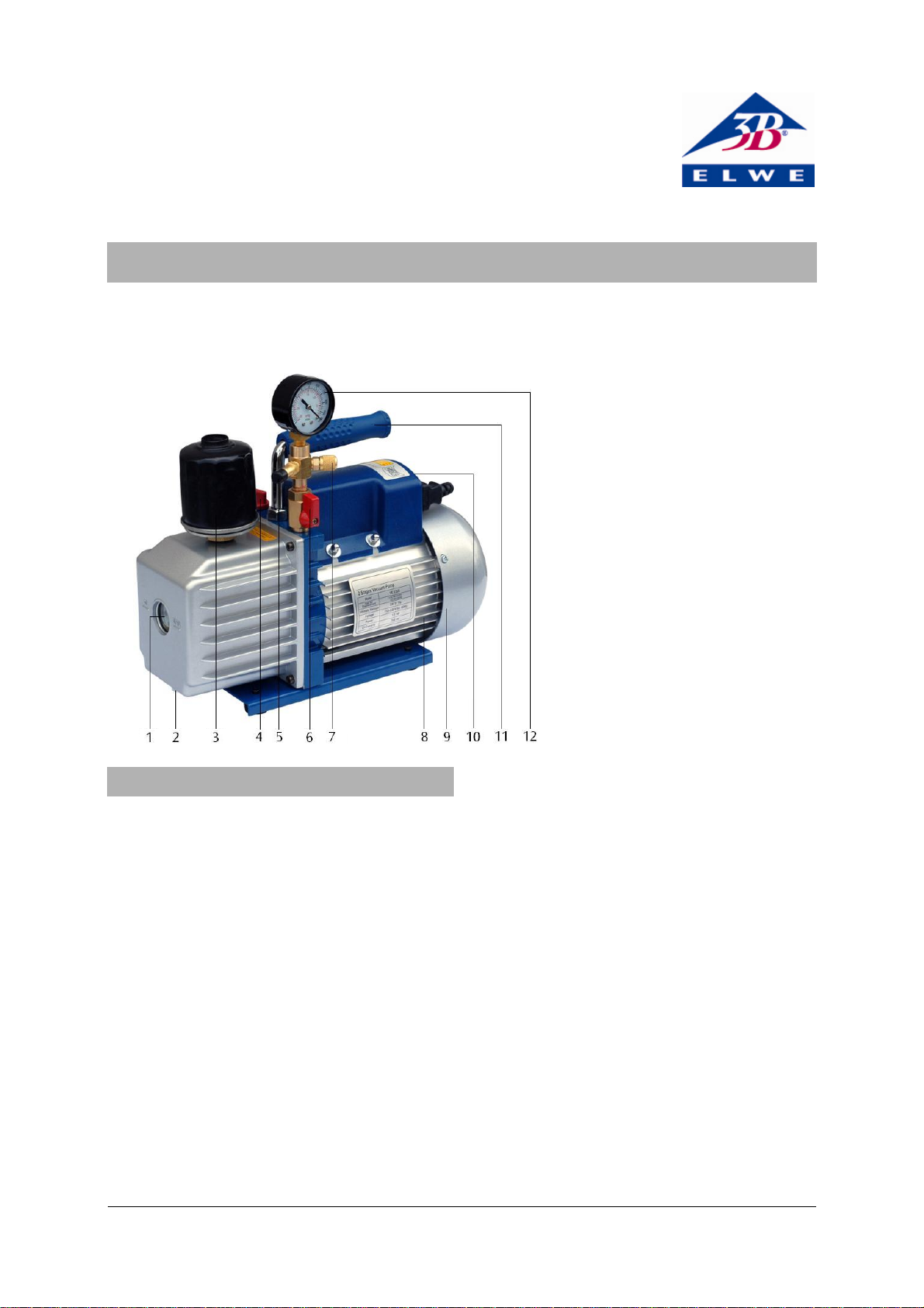
1 Ölstandschauglas
2 Ölablassschraube
3 Abgasfilter
4 Öleinfülldeckel
5 Ansaugstutzen
6 Absperrhahn
7 Belüftungsventil
8 Motor
9 Lüfterdeckel
10 Ein-/Ausschalter und Span-
nungswahlschalter
11 Tragegriff
12 Manometer
1. Sicherheitshinweise
Die Drehschieber-Vakuumpumpe U34000 entspricht
den folgenden europäischen Richtlinien und Normen:
89/336/EEC Elektromagnetische Verträglichkeit
73/23/EEC Niederspannungsrichtlinie
EMC: EN55014-1 (2000) + A2 (2002), EN55014-2 (1997)
+ A1 (2001)
LVD: EN60034-1 (1998) + A11 (2002)
Bei bestimmungsgemäßem Gebrauch ist der sichere
Betrieb der Pumpe gewährleistet. Die Sicherheit ist
jedoch nicht garantiert, wenn die Pumpe unsachgemäß bedient oder unachtsam behandelt wird.
Die Pumpe darf nur zu ihrem bestimmungsgemäßen
Zweck eingesetzt werden. Jede anderweitige Verwendung ist verboten.
Der Hersteller kann für Schäden nicht haftbar gemacht werden, die aus nicht bestimmungsgemäßer
Verwendung entstehen.
Es dürfen keinerlei Veränderungen an der Pumpe
vorgenommen werden.
Bei eventuellen Eingriffen an der Pumpe lehnt der
Hersteller jegliche Verantwortung für die einwandfreie Funktion und den sicheren Betrieb ab.
Wenn anzunehmen ist, dass ein gefahrloser Betrieb
nicht mehr möglich ist (z.B. bei sichtbaren Schäden),
ist die Pumpe unverzüglich außer Betrieb zu setzen
und gegen unbeabsichtigten Betrieb zu sichern.
In Schulen und Ausbildungseinrichtungen ist der
Betrieb des Gerätes durch geschultes Personal verantwortlich zu überwachen.
• Vor Erstinbetriebnahme der Pumpe die Bedie-
nungsanleitung sorgfältig lesen.
• Sicherstellen, dass der Spannungswahlschalter auf
die örtlich übliche Netzspannung eingestellt ist.
• Pumpe nur an Steckdosen mit geerdetem Schutz-
leiter anschließen.
• Pumpe nur durch eine Elektrofachkraft öffnen
bzw. reparieren lassen. Vor Durchführung einer
der genannten Tätigkeiten immer die Netzverbindung durch Ziehen des Steckers trennen.
• Bei Stromausfall die Pumpe aus Sicherheitsgrün-
den abschalten.
1
Page 2
2. Beschreibung
Die Drehschieber-Pumpe U34000 dient zur Durchführung von Vakuumexperimenten zur Evakuierung von
Rezipienten. Sie ist nicht zur industriellen Nutzung
bestimmt.
Die Pumpe U34000 ist eine leistungsstarke, kompakte, zweistufige, ölgedichtete DrehschieberVakuumpumpe. Sie ist mit thermischem Überlastschutz und einem Abgasfilter zur Reduzierung des
Ölnebels im Abgas, einem Manometer und einem
Belüftungsventil ausgestattet.
Aus Transportgründen wird die Pumpe ohne Ölfüllung
ausgeliefert. Eine Flasche Öl, ausreichend zur Erstbefüllung; befindet sich im Lieferumfang.
Die Pumpe verfügt über einen Spannungswahlschalter
(siehe Fig. 1), so dass sie bei Netzspannungen von
110 V oder 230 V plus oder minus 10 % betrieben
werden kann.
3. Technische Daten
Betriebsspannung: 110 – 120 V, 60 Hz
220 – 240 V, 50/60 Hz
Saugvermögen: 100 l/min
Enddruck: 3x10
-1
Pa
Motorleistung: 245 W
Ölfüllmenge: 350 ml
Manometer: 0 – 1000 mbar
Schlaucholive: 10 mm dia.
Abmessungen: ca. 335x138x250 mm
3
Gewicht: ca. 11 kg
Umgebungstemperatur: ca. 5° – 40° C
4. Bedienung
4.1 Allgemeine Hinweise
• Nach dem Auspacken das Verpackungsmaterial
(Beutel, Kartons, Styropor) an einem für Kinder
unzugänglichen Ort lagern.
• Vor Inbetriebnahme der Pumpe prüfen, ob das
Typenschild angebracht ist. Fehlt es, die Pumpe
nicht in Betrieb nehmen und den Vertreiber informieren.
• Falls die Pumpe zurück zum Vertreiber geschickt
wird (z.B. zur Reparatur), Öl ablassen.
• Zur Entsorgung des Öls die örtlichen Vorschriften
beachten.
4.2 Vor der Inbetriebnahme
• Pumpe auf eine waagrechte, stabile Unterlage
stellen.
• Verbindung zur Netzspannung noch nicht herstellen.
• Überprüfen, ob der Spannungswahlschalter in der
richtigen Stellung steht und sicherstellen, dass
sich der Netzschalter in der “Aus”-Position befindet.
• Öleinfülldeckel abschrauben und so viel Öl einfül-
len, bis es am unteren Rand des Ölstandschauglas
sichtbar ist. An Hand der technischen Daten die
richtige Ölfüllmenge der Pumpe überprüfen.
• Öleinfülldeckel wieder einschrauben, Abdeckkap-
pe des Ansaugstutzens abnehmen und Absperrhahn öffnen.
• Motor einschalten.
• Wenn die Pumpe ruhig läuft, Abdeckkappe des
Ansaugstutzens wieder aufsetzen und Absperrhahn schließen. Abhängig von der Raumtemperatur dauert dies ca. 2 bis 30 Sekunden.
• Nach ca. 1 Minute Laufzeit den Ölstand am Öl-
standschauglas auf korrekten Stand überprüfen.
Der Ölstand sollte auf Höhe der Ölstandlinie am
Schauglas sein. Gegebenenfalls Öl nachfüllen.
Hinweis: Ist der Ölstand zu niedrig, kommt es zu einer
Verminderung der Pumpleistung. Zu viel Öl kann
dazu führen, dass Öl durch den Abgasfilter austritt.
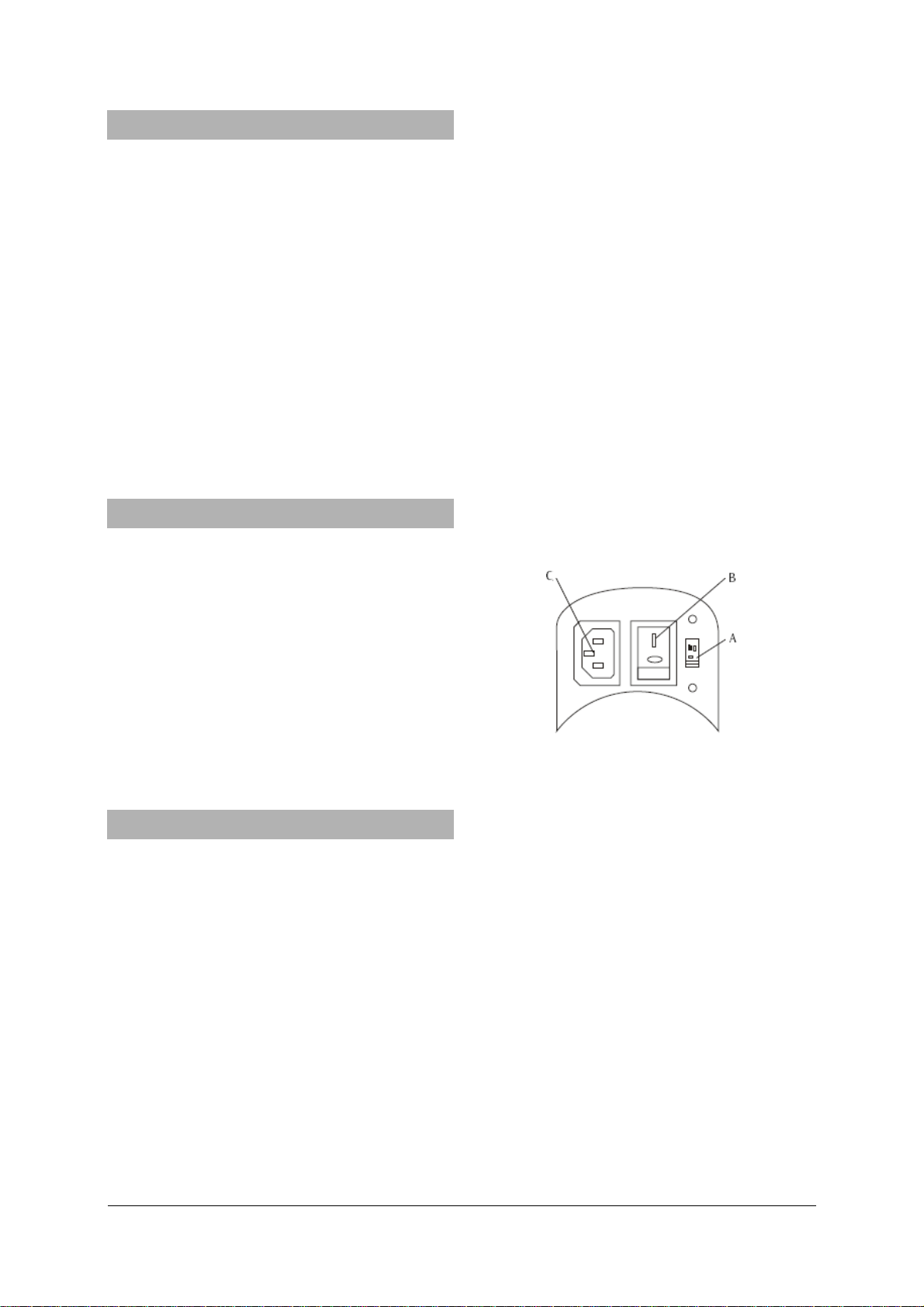
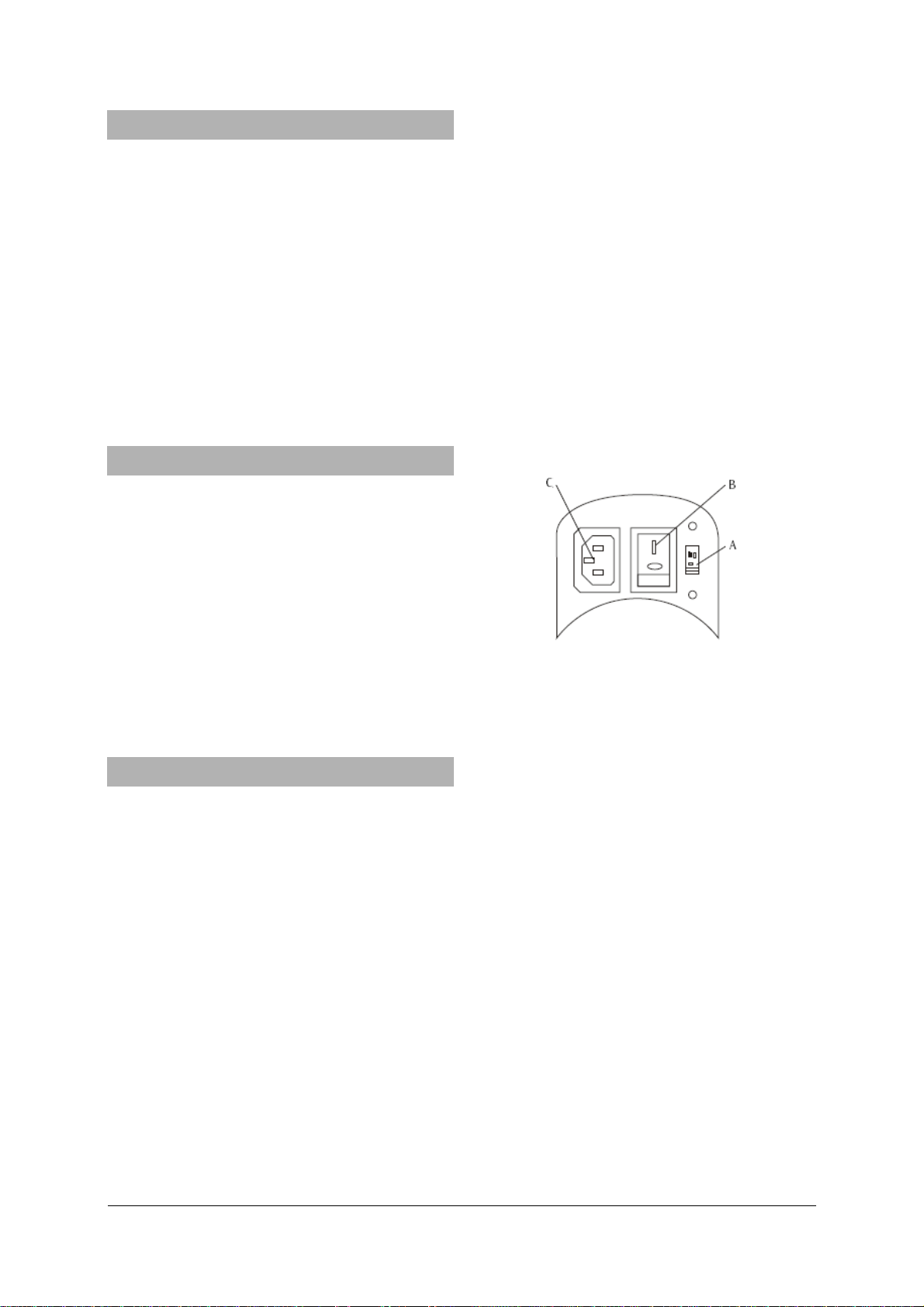
Fig. 1 A Spannungswahlschalter, B Netzschalter, C Steckerbuchse
4.3 Abschalten der Pumpe
Um die Lebensdauer der Pumpe zu verlängern und
gutes Anspringen zu fördern, sollten folgende Schritte
beim Abschalten der Pumpe befolgt werden.
• Absperrhahn schließen.
• Vakuumschlauch entfernen.
• Pumpe abschalten und Absperrhahn für einige
Sekunden öffnen, um etwaiges Vakuum in der
Pumpe auszugleichen.
• Abdeckkappe auf den Ansaugstutzen setzen, um
das Eindringen von Fremdkörpern zu vermeiden.
4.4 Wartung
4.4.1 Vakuumpumpenöl
Zur Erreichung der optimalen Pumpleistung ist der
Typ und der Zustand des verwendeten Pumpenöls
entscheidend. Es sollte nur Vakuumpumpenöl verwendet werden, dessen Zusammensetzung höchste
Viskosität bei normaler Lauftemperatur gewährleistet
2
Page 3

und den Start bei tieferen Temperaturen verbessert.
4.4.2 Ölwechsel
• Vor dem Ölwechsel sicher stellen, dass die Pumpe
auf Betriebstemperatur ist.
• Pumpe vom Netz trennen.
• Ölablassschraube entfernen und verschmutztes Öl
in einem Behälter auffangen. Dabei darauf achten, dass die Dichtung nicht verloren geht.
• Zur Entsorgung des Öls die örtlichen Vorschriften
beachten.
Das Öl kann auch bei laufender Pumpe mit geöffnetem Absperrhahn und teilweise mit einem Tuch abgedecktem Abgasfilter abgelassen werden. Bei dieser
Methode darf die Pumpe aber nicht länger als 20
Sekunden laufen.
• Wenn kein Öl mehr abfließt, Pumpe kippen, um
den Rest des Öls zu entfernen.
• Ölablassschraube wieder einschrauben.
• Öleinfülldeckel abschrauben und neues Vakuum-
öl einfüllen, bis es am unteren Rand des Ölstandschauglas sichtbar ist.
• Sicher stellen, dass der Absperrhahn geschlossen
ist, bevor die Pumpe in Betrieb genommen wird.
• Pumpe ca. 1 Minute laufen lassen, dann den
Ölstand überprüfen.
• Befindet sich der Ölstand unter der Ölstandlinie
am Schauglas, bei laufender Pumpe langsam Öl
nachfüllen bis es die Ölstandlinie erreicht.
• Öleinfülldeckel wieder aufschrauben, sicher stel-
len, dass der Absperrhahn geschlossen ist und die
Ölablassschraube fest sitzt.
Wenn das Öl stark mit Ölschlamm verschmutzt ist,
kann folgende Methode benutzt werden, um das Öl
zu entfernen.
• Pumpe laufen lassen, bis sie Betriebstemperatur
erreicht hat.
• Bei laufender Pumpe Ölablassschraube entfer-
nen. Dabei darauf achten, dass die Dichtung nicht
verloren geht.
• Abgasfilter mit einem Tuch teilweise abdecken.
Dadurch wird im Ölbehälter aufgebaut, der den Ölschlamm herausdrückt.
• Pumpe abschalten, wenn kein Öl mehr fließt.
• Prozedur wiederholen, bis die Verschmutzung
beseitigt ist.
• Ölablassschraube wieder einschrauben und die
korrekte Menge neues Öl einfüllen.
5. Hinweise zur Fehlerbeseitigung
5.1 Pumpe springt nicht an
• Überprüfen, ob der Spannungswahlschalter in der
richtigen Position steht.
5.2. Öl läuft aus
• Überprüfen, ob das ausgelaufene Öl keine Rest-
ansammlung von Schüttverlust etc. ist.
Falls das Leck an der Pumpe auftritt, muss entweder
die Gehäusedichtung oder die Wellendichtung ausgewechselt werden.
• Pumpe zwecks Reparatur an den Hersteller schi-
cken.
Falls die Ölablassschraube undicht ist,
• Ölablassschraube mit einem handelsüblichen
Dichtungsring abdichten.
5.3. Verminderte Pumpenleistung
• Sicherstellen, dass das Manometer und alle Ver-
bindungsleitungen in gutem Zustand und dicht
sind.
• Zur Überprüfung der Dichtheit Vakuumpumpenöl
auf die vermuteten Stellen an der Pumpe und
den Zuleitungen auftragen. Die Pumpleistung
steigt kurz an, da das Öl als Dichtmittel wirkt.
• Sicher stellen, dass das Pumpenöl sauber ist.
Eine stark verschmutzte Pumpe könnte mehrere Ölspülungen benötigen.
• Sicher stellen, dass der Ölstand korrekt ist.
Zur Erreichung einer maximalen Pumpleistung muss
der Ölstand bei laufender Pumpe auf Höhe der
Ölstandlinie am Schauglas sein.
• Nicht zuviel Öl einfüllen.
Bei Betriebstemperatur dehnt sich das Öl aus und ein
höherer Ölstand wird angezeigt als bei nicht laufender Pumpe.
• Um den Ölstand zu überprüfen, Pumpe bei ge-
schlossenem Absperrhahn laufen lassen.
• Ölstand überprüfen und gegebenenfalls Öl nach-
füllen.
5.4 Automatisches Abschalten
Die Pumpe ist mit einem thermischen Überlastschutz
ausgestattet. Bei zu hoher Umgebungstemperatur
schaltet die Pumpe automatisch ab.
• Netzspannung nicht sofort abschalten.
Falls die Pumpe nach 3 Minuten nicht wieder automatisch anläuft,
• Pumpe durch Herabsetzen der Umgebungstem-
peratur abkühlen lassen und so die Lebensdauer
der Pumpe verlängern.
3B Scientific GmbH • Rudorffweg 8 • 21031 Hamburg • Deutschland • www.3bscientific.com
Technische Änderungen vorbehalten
© Copyright 2008 3B Scientific GmbH
Page 4

Page 5

3B SCIENTIFIC® PHYSICS
Rotary-Vane Vacuum Pump, Two-Stage with Manometer U34000
Instruction sheet
08/08 ALF
1 Oil sight glass
2 Oil drain cap
3 Exhaust filter
4 Oil fill cap
5 Hose nipple
6 Stopcock
7 Ventilation valve
8 Motor
9 Fan cover
10 Power switch and voltage
selector switch
11 Carrying handle
12 Manometer
1. Safety instructions
The rotary-vane pump U34000 is in accordance with
the following applicable European directives and
standards:
89/336/EEC Electromagnetic Compatibility
73/23/EEC Low Voltage Directive
EMC: EN55014-1 (2000) + A2 (2002), EN55014-2 (1997)
+ A1 (2001)
LVD: EN60034-1 (1998) + A11 (2002)
Safe operation of the pump is guaranteed, provided it
is used correctly. However, there is no guarantee of
safety if the equipment is used in an improper or
careless manner.
The pump may only be used for its intended use. Any
other use is to be considered improper.
The manufacturer cannot be held responsible for
damages caused by improper use of the pump.
Under no circumstance must the pump be altered or
tampered with.
In case of tempering the manufacturer declines any
responsibility for the functioning and safety of the
pump.
If it may be assumed for any reason that nonhazardous operation will not be possible (e.g. visible
damage), the pump should be switched off immediately and secured against any unintended use.
In schools and other educational institutions, the
operation of the pump must be supervised by qualified personnel.
• Before setting up and using the pump for the first
time, read the manual carefully.
• Confirm that the voltage selector switch is set to
the local mains voltage.
• The pump may only be connected to the mains
via a socket that has an earth connection.
• The pump may only be opened/repaired by quali-
fied and trained personnel. Always disconnect the
pump by pulling the mains plug before proceeding to any of the mentioned operations.
• In case of power failure during operation, turn
the pump off for safety reasons.
1
Page 6
2. Description
The rotary-vane pump U34000 must only be used in
vacuum experiments to depressurize vacuum containers. It is not designed for commercial use.
The pump U34000 is a high performance, compact,
two-stage, oil-sealed rotary vane pump. It is protected
against thermal overload and equipped with an exhaust filter to reduce oil mist, a manometer and a
ventilation valve.
For reasons of transport the pump is delivered with
no oil in the reservoir. In the package you should find
a bottle of oil, sufficient for the first filling.
The pump is equipped with a voltage selector switch
(refer to fig. 1), so that it can be operated with mains
voltages of 110 V or 230 V plus or minus 10 %.
3. Technical data
Power supply: 110 – 120 V, 60 Hz
220 – 240 V, 50/60 Hz
Suction capacity: 100 l/min
Final pressure: 3x10
-1
Pa
Motor power: 245 W
Oil capacity: 350 ml
Manometer: 0 – 1000 mbar
Hose nipple: 10 mm dia.
Dimensions: approx. 335x138x250 mm
3
Weight: approx. 11 kg
Ambient temperature: 5° – 40° C approx.
4. Operation
4.1 General information
• After unpacking, please place all parts of the
package (bags, boxes, polystyrene sides) away
from the reach of children.
• Check the presence of the data label on the hos-
ing. If the label is not present, do not use the
pump and inform the supplier.
• In case you need to send back the pump to the
distributer (e.g. repair) drain the oil.
• For the disposal of the oil adhere to the local
regulations.
4.2 Before operating the pump
• Place the pump horizontally on a stable support.
• Do not connect the pump yet to the mains volt-
age.
• Check that the voltage selector switch is set to the
local mains voltage and ensure that the power
switch is in the OFF position before connecting
the pump to a power source.
• Remove the oil fill cap and add oil until it shows
at the bottom of the sight glass. Refer to the
technical data for the correct oil capacity of the
pump.
• Screw back the oil fill cap, remove the cap from
the hose nipple and open the stopcock.
• Turn the motor switch to ON position.
• When the pump runs smoothly put the cap back
onto the hose nipple and close the stopcock. This
may take 2 to 30 seconds depending on the ambient temperature.
• After the pump operates for approximately one
minute, check the sight glass for proper oil level,
which should be aligned with the sight glass oil
level line. Refill oil if necessary.
Note: Insufficient oil filling will result in poor vacuum
performance. Excessive oil can result in overflowing of
oil from the exhaust fitting.
Fig. 1 A voltage selector switch, B power switch, C socket
4.3 To shut off the pump after use
To prolong life span of the pump and a smooth startup, these procedures to shut off the pump should be
followed.
• Close the stopcock.
• Remove the hose from the hose nipple.
• Switch off the pump and open the stopcock for a
few seconds to relieve any vacuum inside the
pump.
• Place the cap on the hose nipple to prevent any
contamination or foreign particles from entering
it.
4.4 Maintenance
4.4.1 Vacuum pump oil
The condition and the type of oil used in any high
performance vacuum pump are extremely important
in determining the ultimate attainable vacuum. It is
recommended to use the high performance vacuum
pump oil, which is specifically blended to maintain
maximum viscosity at normal running temperatures
and to improve cold weather start up.
4.4.2 Oil change
• Ensure that the pump is warmed up.
2
Page 7

Pull the mains plug.
•
• Remove the oil drain cap and drain the contami-
nated oil into a container. Take care not lose the
oil drain gasket.
• Dispose of the oil adhering to the local regula-
tions.
Oil can also be removed from the pump by opening
the stopcock and partially blocking the exhaust with a
cloth while the pump is running. Do not operate the
pump for more than 20 seconds using this method.
• When the drainage of oil completed, tilt the
pump forward to remove the residual oil.
• Screw in the oil drain cap.
• Remove the oil fill cap and fill the oil reservoir
with new vacuum pump oil until oil is seen at the
bottom of the sight glass.
• Ensure that the stopcock is closed before turning
on the pump.
• Allow it to run for one minute before checking
the oil level.
• If the oil level is below the sight glass oil level
line, fill oil slowly (with the pump running) until
the oil reaches the oil level line.
• Place back the oil fill cap, ensure the stopcock is
closed and the oil drain cap is closed tightly.
If the oil is badly contaminated with sludge that
forms during operation, you may use the following
method to remove the oil from the pump reservoir.
• Leave the pump running until it is warmed up.
• While the pump is still running, remove the oil
drain cap. Take care not lose the oil drain gasket.
• Restrict the exhaust slightly.
This will back-pressure the oil reservoir and force out
the sludge.
• Turn off the pump when the oil stops flowing.
• Repeat this procedure as required until the con-
taminants are removed.
• Screw in the oil drain cap and refill the oil reser-
voir to the proper oil level with clean vacuum
pump oil.
5. Troubleshooting guide
• Contact the distributor.
If leakage exists in the area of the oil drain plug,
• reseal the plug using a commercial pipe thread
sealer.
5.3. Failure to attain a good vacuum
• Ensure the vacuum gauge and all connections are
in good condition and leak free.
• Confirm leakage by monitoring the vacuum with
the manometer while applying vacuum pump oil
at connections or suspected leak points. The vacuum will improve briefly while the oil is sealing
the leak.
• Ensure the pump oil is clean.
A badly contaminated pump may require several oil
flushes.
• Ensure the oil is at the proper level.
For optimum pump operation, the oil must be even
with the oil level line on the sight glass when the
pump is running.
• Do not overfill as operating temperatures will
cause the oil to expand, which will appear at a
higher level than when the pump is not running.
• To check the oil level, start the pump with the
stopcock closed.
• Check the oil level in the sight glass. Add oil if
necessary.
5.4 Automatic shut down
The pump is equipped with a thermal protection
function. If the ambient temperature is too hot, the
product may stop functioning.
• Do not to switch off the power supply immedi-
ately.
If the pump does not re-start automatically after 3
minutes,
• cool the pump by lowering the ambient tempera-
ture to prolong the lifespan of the vacuum pump.
5.1 Failure to start
• Check if the voltage selector switch is in the right
position.
5.2. Oil leakage
• Ensure that that the oil is not a residual accumu-
lation of spillage etc.
If leakage exists, the housing gasket or the shaft seal
may need to be replaced.
3B Scientific GmbH • Rudorffweg 8 • 21031 Hamburg • Germany • www.3bscientific.com
Subject to technical amendments
© Copyright 2008 3B Scientific GmbH
Page 8

Page 9

3B SCIENTIFIC® PHYSICS
Pompe à vide à tiroir rotatif à deux étages avec manomètre
U34000
Instructions d'utilisation
08/08 ALF
1 Indicateur d'huile
2 Vis de purge d'huile
3 Filtre de gaz d'échappement
4 Couvercle de remplissage
d'huile
5 Tubulure d'aspiration
6 Robinet d'arrêt
7 Soupape d'aération
8 Moteur
9 Couvercle de ventilateur
10 Interrupteur principal et
sélecteur de tension
11 Poignée
12 Manomètre
1. Consignes de sécurité
La pompe à vide à tiroir rotatif U34000 satisfait aux
directives et normes européennes suivantes :
89/336/EEC Compatibilité électromagnétique
73/23/EEC Directive sur les basses tensions
EMC : EN55014-1 (2000) + A2 (2002), EN55014-2 (1997)
+ A1 (2001) LVD : EN60034-1 (1998) + A11 (2002)
En cas d'utilisation conforme, l'exploitation sûre de la
pompe est garantie. En revanche, la sécurité n'est pas
garantie si la pompe n'est pas manipulée dans les
règles ou sans attention.
La pompe ne doit être utilisée qu'aux fins auxquelles
elle est destinée. Toute autre utilisation est interdite.
Le constructeur décline toute responsabilité pour des
dommages résultant d'un emploi non conforme.
Il est interdit de procéder à des modifications sur la
pompe.
En cas d'interventions sur la pompe, le constructeur
décline toute responsabilité pour un parfait
fonctionnement et une exploitation sûre.
S'il s'avère qu'une exploitation peu sûre n'est plus
possible (par ex. en présence de dommages
apparents), mettez la pompe immédiatement hors
service et protégez-la contre tout emploi involontaire.
Dans les écoles et les établissements de formation,
l'utilisation de l'appareil doit être surveillée par un
personnel formé.
• Avant de mettre la pompe en service pour la
première fois, lisez attentivement les instructions
d'utilisation.
• Assurez-vous que le sélecteur de tension est réglé
sur la tension secteur usuelle.
• Ne branchez la pompe qu'à des prises de courant
avec mise à la terre du neutre.
• Seul un électricien est autorisé à ouvrir et / ou à
réparer la pompe. Avant d'effectuer l'une des
activités mentionnées, retirez toujours le cordon
du secteur.
• En cas de panne de courant, éteignez la pompe
pour des raisons de sécurité.
1
Page 10

2. Description
La pompe à tiroir rotatif U34000 permet de réaliser
des expériences visant à faire le vide dans des
récipients. Elle n'est pas destinée à un emploi
industriel.
La pompe U34000 est une pompe à vide à tiroir
rotatif puissante, compacte, à deux étages, étanche à
l'huile. Elle est équipée d'une protection thermique
contre les surcharges et d'un filtre de gaz
d'échappement réduisant le brouillard d'huile dans
les gaz d'échappement, d'un manomètre et d'une
soupape d'aération.
Pour des raisons de transport, la pompe est livrée
sans remplissage d'huile. Un flacon d'huile, suffisant
pour le premier remplissage, est fourni.
La pompe dispose d'un sélecteur de tension (voir la
fig. 1) qui permet de l'exploiter à des tensions secteur
de 110 ou 220 V, plus ou moins 10%.
3. Caractéristiques techniques
Tension d'alimentation : 110 – 120 V, 60 Hz
220 – 240 V, 50/60 Hz
Capacité d'aspiration : 100 l/min
Pression finale : 3x10
-1
Pa
Puissance du moteur : 245 W
Remplissage d'huile : 350 ml
Manomètre : 0 – 1000 mbar
Olive : 10 mm de diamètre
Dimensions : env. 335x138x250 mm
3
Poids : env. 11 kg
Température ambiante : env. 5° – 40° C
4. Manipulation
4.1 Notes générales
• Après avoir déballé la pompe, rangez le matériel
d'emballage (sachet, cartons, polystyrène) à un
endroit inaccessible pour les enfants.
• Avant de mettre la pompe en service, vérifiez que
la plaque signalétique est apposée. Si elle
manque, ne mettez pas la pompe en service et
informez-en le revendeur.
• Avant de renvoyer la pompe au revendeur (par ex.
pour une réparation), purgez-en l'huile.
• Lorsque vous éliminez l'huile, respectez les
prescriptions locales.
4.2 Avant la mise en service
• Posez la pompe sur un support horizontal et
stable.
• N'établissez pas encore la connexion avec la
tension secteur.
• Vérifiez que le sélecteur de tension est réglé
correctement et assurez-vous que l'interrupteur
secteur se trouve en position « Hors ».
• Dévissez le couvercle de remplissage d'huile et
remplissez de l'huile, jusqu'à ce qu'elle soit
visible sur le bord inférieur de l'indicateur
d'huile. Vérifiez la quantité de remplissage à
l'aide des caractéristiques techniques.
• Remettez le couvercle, retirez la protection de la
tubulure d'aspiration et ouvrez le robinet d'arrêt.
• Allumez le moteur.
• Lorsque la pompe marche tranquillement,
remettez la protection de la tubulure et refermez
le robinet d'arrêt. Selon la température
ambiante, cette opération peut durer entre deux
et trente secondes.
• Après environ une minute de marche, vérifiez le
niveau d'huile dans l'indicateur. Le niveau
d'huile doit se situer sur la ligne de l'indicateur.
Au besoin, rajoutez de l'huile.
Note : si le niveau d'huile est trop faible, le débit de
la pompe sera réduit. Trop d'huile peut avoir pour
conséquence que de l'huile s'échappe à travers le
filtre de gaz d'échappement.
Fig. 1 A sélecteur de tension, B interrupteur secteur, C
connecteur
4.3 Mise hors service de la pompe
Pour prolonger la durée de vie de la pompe et
garantir son bon démarrage, nous vous
recommandons de suivre la procédure suivante pour
mettre la pompe hors service.
• Fermez le robinet d'arrêt.
• Retirez le tuyau à vide.
• Mettez la pompe hors service et ouvrez le robinet
d'arrêt pendant quelques secondes pour
compenser un éventuel vide dans la pompe.
• Placez la protection sur la tubulure d'aspiration
pour éviter la pénétration de corps étrangers.
4.4 Entretien
4.4.1 Huile de pompe
Le type et l'état de l'huile utilisée déterminent le
rendement optimal de la pompe. N'utilisez que de
2
Page 11

l'huile dont la composition garantit une viscosité
maximale à température de fonctionnement normale
et améliore le démarrage à basses températures.
4.4.2 Vidange d´huile
• Avant de remplacer l'huile, assurez-vous que la
pompe soit à température de service.
• Coupez la pompe du secteur.
• Retirez la vis de purge et récupérez l'huile sale
dans un récipient. Veillez à ne pas perdre le joint.
• Lorsque vous éliminez l'huile, respectez les
prescriptions locales.
L'huile peut aussi être purgée lorsque la pompe est en
marche. Le robinet d'arrêt doit alors être ouvert et le
filtre de gaz d'échappement recouvert en partie par
un chiffon. Par cette méthode, la pompe ne doit pas
marcher plus de vingt secondes.
• Si de l'huile ne s'écoule plus, basculez la pompe
pour enlever le reste d'huile.
• Remettez la vis de purge.
• Dévissez le couvercle de remplissage et remplissez
de l'huile neuve, jusqu'à ce qu'elle soit visible sur
le bord inférieur de l'indicateur d'huile.
• Avant de mettre la pompe en service, assurez-
vous que le robinet d'arrêt est fermé.
• Faites marcher la pompe pendant environ une
minute, puis vérifiez le niveau d'huile.
• Si le niveau d'huile se situe au-dessous de la ligne
de l'indicateur, rajoutez lentement de l'huile
pendant la marche de la pompe, jusqu'à ce
qu'elle atteigne la ligne.
• Remettez le couvercle, assurez-vous que le
robinet d'arrêt est fermé et que la vis de purge est
bien serrée.
Si l'huile est fortement encrassée par de la boue,
procédez comme suit pour enlever l'huile.
• Faites marcher la pompe, jusqu'à ce qu'elle
atteigne sa température de service.
• La pompe étant en marche, retirez la vis de purge
d'huile. Veillez à ne pas perdre le joint.
• Recouvrez en partie le filtre de gaz
d'échappement avec un chiffon.
Dans le réservoir d'huile, il se forme alors une
pression qui évacue la boue.
• Si de l'huile ne s'échappe plus, mettez la pompe
hors service.
• Répétez la procédure, jusqu'à ce que
l'encrassement soit éliminé.
• Remettez la vis de purge et remplissez la quantité
correcte d'huile neuve.
5. Notes sur l'élimination d'erreurs
5.1 La pompe ne démarre pas
• Vérifiez que le sélecteur de tension est réglé en
bonne position.
5.2. De l'huile s'échappe
• Vérifiez que l'huile écoulée n'est pas une
accumulation résiduelle de pertes de versement,
etc.
Si la fuite apparaît sur la pompe, remplacez soit le
joint du carter, soit le joint de l'arbre.
• Envoyez la pompe au constructeur aux fins de
réparation.
Si la vis de purge n'est pas étanche,
• étanchéifiez la vis avec un anneau étanche usuel.
5.3. Débit réduit
• Assurez-vous que le manomètre et toutes les
conduites de raccord sont en bon état et bien
étanches.
• Pour vérifier l'étanchéité, appliquez de l'huile
aux endroits supposés non étanches de la pompe
et des conduites d'alimentation. Le débit de la
pompe augmente brièvement, car l'huile a un
effet étanchéifiant.
• Assurez-vous que l'huile est propre.
Une pompe fortement encrassée peut nécessiter
plusieurs rinçages d'huile.
• Assurez-vous que le niveau d'huile est correct.
Pour obtenir un débit optimal, le niveau d'huile doit
se situer à hauteur de la ligne de l'indicateur, la
pompe étant en marche.
• Ne remplissez pas trop d'huile.
À température de service, l'huile se dilate et le niveau
d'huile affiché est supérieur à celui lorsque la pompe
n'est pas en marche.
• Pour vérifier le niveau d'huile, faites marcher la
pompe avec le robinet d'arrêt fermé.
• Vérifiez le niveau d'huile et, au besoin, rajoutez
de l'huile.
5.4 Mise hors service automatique
La pompe est équipée d'une protection thermique
contre les surcharges. Si la température ambiante est
trop élevée, la pompe se met automatiquement hors
service.
• Ne pas coupez tout de suite la tension secteur.
Si la pompe ne redémarre pas automatiquement
après trois minutes,
• laissez la pompe refroidir en réduisant la
température ambiante pour prolonger ainsi sa
durée de vie.
3B Scientific GmbH ▪ Rudorffweg 8 ▪ 21031 Hamburg ▪ Allemagne ▪ www.3bscientific.com
Sous réserve de modifications techniques
© Copyright 2008 3B Scientific GmbH
Page 12

Page 13

3B SCIENTIFIC® PHYSICS
Pompa per vuoto a palette, a due stadi con manometro U34000
Istruzioni per l'uso
08/08 ALF
1 Vetro spia del livello dell'olio
2 Vite di scarico dell'olio
3 Filtro gas di scarico
4 Coperchio di introduzione
dell'olio
5 Attacco di aspirazione
6 Rubinetto di intercettazione
7 Valvola di ventilazione
8 Motore
9 Coperchio della ventola
10 Interruttore ON/OFF e selettore
di tensione
11 Maniglia di trasporto
12 Manometro
1. Norme di sicurezza
La pompa per vuoto a palette U34000 rispetta le
seguenti direttive e norme europee:
89/336/EEC Compatibilità elettromagnetica
73/23/EEC Direttiva bassa tensione
EMC: EN55014-1 (2000) + A2 (2002), EN55014-2 (1997)
+ A1 (2001)
LVD: EN60034-1 (1998) + A11 (2002)
Un utilizzo conforme garantisce il funzionamento
sicuro della pompa.. La sicurezza non è tuttavia
garantita se la pompa non viene utilizzata in modo
appropriato o non viene trattata con cura.
La pompa deve essere utilizzato soltanto
conformemente al suo scopo. È vietato qualsiasi
utilizzo diverso.
Il produttore non può rispondere per danni dovuti a
un utilizzo non conforme.
Non deve essere apportata nessuna modifica alla
pompa.
In caso di eventuali interventi sulla pompa, il
produttore non si assume nessuna responsabilità
riguardo al funzionamento adeguato e sicuro
Se si ritiene che non sia più possibile un
funzionamento privo di pericoli (ad es. in caso di
danni visibili), la pompa deve essere messa
immediatamente fuori servizio e al sicuro da
eventuali azionamenti accidentali. .
Negli istituti scolastici e nelle strutture per la
formazione l’uso dell’apparecchio deve essere
monitorato in modo responsabile da personale
istruito.
• Prima della prima messa in funzione della pompa
leggere accuratamente le istruzioni per l'uso.
• Accertarsi che il selettore di tensione sia
impostato sulla tensione di rete locale.
• Collegare la pompa solo a prese con conduttore
di protezione collegato a terra.
• Far aprire o riparare l'apparecchio solo da un
elettricista esperto. Prima dell'esecuzione di tali
attività staccare sempre l'alimentazione di rete
estraendo la spina.
• In caso di caduta di corrente spegnere la pompa
per motivi di sicurezza.
1
Page 14

2. Descrizione
La pompa a palette U34000 consente l'esecuzione di
• Svitare il coperchio di introduzione dell'olio e
esperimenti sul vuoto relativi alla creazione del vuoto
in recipienti. Non è destinata a un uso industriale.
La pompa U34000 è una pompa per vuoto a palette
ad alte prestazioni, compatta, a due stadi, a tenuta
d'olio. È dotata di una protezione da sovraccarico
• Avvitare nuovamente il coperchio di introduzione
termica e di un filtro del gas di scarico per la
riduzione della nebbia d'olio nel gas di scarico, di un
manometro e di una valvola di ventilazione.
Per ragioni di trasporto la pompa viene fornita senza
il riempimento d'olio. Nel volume di fornitura si ha
• Accendere il motore.
• Se la pompa funziona silenziosamente,
una bottiglia d'olio, sufficiente per il primo
riempimento.
La pompa dispone di un selettore di tensione (vedere
la figura 1), cosicché è possibile attivarla a tensioni di
rete di 110 V o 230 V più o meno il 10%.
• Dopo un funzionamento di circa 1 minuto
3. Dati tecnici
Tensione d'esercizio: 110 – 120 V, 60 Hz
220 – 240 V, 50/60 Hz
Portata: 100 l/min
Pressione finale: 3x10
-1
Pa
Potenza del motore: 245 Ω
Riempimento d'olio: 350 ml
Nota: Se il livello dell'olio è troppo basso si determina
una riduzione della portata della pompa. Olio in
eccesso può far sì che l'olio fuoriesca attraverso il
filtro del gas di scarico
Manometro: 0 – 1000 mbar
Nipplo per tubo: 10 mm dia.
Dimensioni: ca. 335x138x250 mm
3
Peso: ca. 11 kg
Temperatura ambiente: ca. 5° – 40° C
4. Utilizzo
4.1 Indicazioni generali
• Dopo il disimballo conservare il materiale di
imballaggio (sacchetto, carton, Styropor) in un
luogo fuori dalla portata dei bambini.
• Prima della messa in funzione della pompa
verificare la presenza della targhetta. Se manca,
non mettere in funzione la pompa e informare il
distributore.
• Qualora la pompa venga spedita indietro al
distributore (ad esempio per riparazione),
Fig. 1 A Selettore di tensione, B Interruttore di rete, C Presa
4.3 Spegnimento della pompa
Al fine di prolungare la durata della pompa e favorire
una buona messa in moto, è necessario seguire le
seguenti fasi per lo spegnimento della pompa.
• Chiudere il rubinetto di intercettazione
• Rimuovere il tubo flessibile del vuoto
• Spegnere la pompa e aprire per alcuni secondi il
scaricare l'olio
• Per lo smaltimento dell'olio rispettare le
disposizioni locali.
• Collocare il tappo di copertura sull'attacco di
4.2 Prima della messa in funzione
• Collocare la pompa su una base orizzontale,
stabile.
• Non effettuare ancora il collegamento alla rete.
• Verificare che il selettore di tensione si trovi nella
posizione corretta e accertarsi che l'interruttore
4.4 Manutenzione
4.4.1 Olio per la pompa per vuoto
Il tipo e lo stato dell'olio per la pompa utilizzato è
decisivo al fine di ottenere la portata ottimale della
di rete sia in posizione "OFF".
versare olio finché non è visibile sul bordo
inferiore del vetro spia del livello dell'olio.
Verificare il corretto riempimento d'olio della
pompa in base ai dati tecnici.
dell'olio, rimuovere il tappo di copertura
dell'attacco di aspirazione e aprire il rubinetto di
intercettazione.
riposizionare il tappo di copertura dell'attacco di
aspirazione e chiudere il rubinetto di
intercettazione. A seconda della temperatura
ambiente questo richiede all'incirca da 2 a 30
secondi.
controllare la correttezza del livello dell'olio sul
vetro spia del livello dell'olio. Il livello dell'olio
dovrebbe essere all'altezza della linea del livello
dell'olio sul vetro spia Se necessario rabboccare
l'olio
rubinetto di intercettazione, per compensare
l'eventuale vuoto nella pompa.
aspirazione per evitare la penetrazione di corpi
estranei.
2
Page 15

pompa. Dovrebbe essere utilizzato soltanto olio per
pompe per vuoto con una composizione che
garantisca la massima viscosità alla normale
temperatura di funzionamento e l'avvio alle
temperature più basse.
4.4.2 Cambiamento dell'olio
• Prima di cambiare l'olio, accertarsi che la pompa
sia alla temperatura di esercizio
• Scollegare la pompa dalla rete.
• Rimuovere la vite di scarico dell'olio e raccogliere
l'olio in un contenitore A questo proposito, fare
attenzione a non perdere la guarnizione
• Per lo smaltimento dell'olio rispettare le
disposizioni locali.
L'olio può essere scaricato anche quando la pompa è
in funzione con rubinetto di intercettazione aperto e
filtro del gas di scarico parzialmente coperto con un
panno. Nel caso di tale metodo, però, la pompa non
può rimanere in funzione per più di 20 secondi.
• Se non defluisce più olio, ribaltare la pompa per
rimuovere il residuo d'olio.
• Avvitare nuovamente la vite di scarico dell'olio.
• Svitare il coperchio di introduzione dell'olio e
versare nuovo olio per vuoto finché non è visibile
sul bordo inferiore del vetro spia del livello
dell'olio.
• Prima di mettere in funzione la pompa accertarsi
che il rubinetto di intercettazione sia chiuso.
• Lasciar funzionare la pompa per circa 1 minuto e
in seguito controllare il livello dell'olio
• Se il livello dell'olio è al di sotto della linea del
livello dell'olio sul vetro spia, rabboccare olio
lentamente con pompa in funzione, finché non
raggiunge la linea del livello dell'olio.
• Riavvitare il coperchio di introduzione dell'olio e
accertarsi che il rubinetto dell'olio sia chiuso e la
vite di scarico dell'olio sia fissata saldamente.
Se l'olio è fortemente imbrattato con la morchia
dell'olio, si possono utilizzare i seguenti metodi per
rimuovere l'olio.
• Lasciare in funzione la pompa, finché non ha
raggiunto la temperatura di esercizio.
• Rimuovere la vite di scarico dell'olio con pompa
in funzione. A questo proposito, fare attenzione a
non perdere la guarnizione.
• Coprire parzialmente il filtro del gas di scarico
con un panno.
In questo modo si crea una pressione nel contenitore
dell'olio che preme fuori la morchia dell'olio.
• Spegnere la pompa se non defluisce più olio
• Ripetere la procedura finché la sporcizia non è
eliminata.
• Riavvitare nuovamente la vite di scarico dell'olio
e versare la corretta quantità di olio nuovo.
5. Indicazioni per la correzione degli errori
5.1 La pompa non si avvia
• Verificare che il selettore di tensione sia nella
posizione corretta.
5.2. Fuoriesce olio
• Verificare che l'olio fuoriuscito non sia un
accumulo residuo di perdite di dispersione etc.
Se la perdita si presenta in corrispondenza della
pompa, occorre sostituire la guarnizione
dell'alloggiamento o la guarnizione dell'albero.
• Spedire la pompa al costruttore a scopi di
riparazione.
Se la vite di scarico dell'olio non è ermetica,
• Chiudere a tenuta la vite di scarico dell'olio con
un anello di tenuta normalmente reperibile in
commercio.
5.3. Portata della pompa ridotta
• Accertarsi che il manometro e tutte le linee di
collegamento siano in buono stato ed ermetiche.
• Per la verifica dell'ermeticità apportare olio per la
pompa per vuoto sui punti ipotizzati in
corrispondenza della pompa e delle
alimentazioni. La portata della pompa aumenta
poco, poiché l'olio agisce da mezzo di tenuta.
• Accertarsi che l'olio della pompa sia pulito.
Per una pompa molto sporca potrebbero rendersi
necessari diversi lavaggi con olio.
• Accertarsi che il livello dell'olio sia corretto.
Per conseguire la portata massima della pompa il
livello dell'olio con pompa in funzione deve essere
all'altezza della linea del livello dell'olio.
• Non versare troppo olio
Alla temperatura di esercizio l'olio si espande e viene
indicato un livello dell'olio superiore a quello con
pompa non in funzione.
• Per controllare il livello dell'olio, far funzionare
la pompa con rubinetto di intercettazione chiuso.
• Verificare il livello dell'olio e, se necessario,
rabboccare l'olio.
5.4 Spegnimento automatico
La pompa è dotata di una protezione da sovraccarico
termica. In caso di temperatura ambiente troppo
elevata la pompa si spegne automaticamente.
• Non disinserire immediatamente la tensione di
rete.
Se la pompa non si riavvia automaticamente entro 3
minuti,
• Far raffreddare la pompa riducendo la
temperatura ambiente e prolungare così la
durata della pompa.
3B Scientific GmbH • Rudorffweg 8 • 21031 Amburgo • Germania • www.3bscientific.com
Con riserva di modifiche tecniche
© Copyright 2008 3B Scientific GmbH
Page 16

Page 17

3B SCIENTIFIC® PHYSICS
Bomba de vacío rotativa de paletas, de dos etapas con manómetro U34000
Instrucciones de uso
08/08 ALF
1 Mirilla de nivel de aceite
2 Tornillo de vaciado de aceite
3 Filtro de purga
4 Tapa de llenado de aceite
5 Tubuladura de aspiración
6 Llave de bloqueo
7 Válvula de ventilación
8 Motor
9 Tapa de ventilador
10 Conector/Desconector y
conmutador selector de
tensión
11 Asa de transporte
12 Manómetro
1. Advertencias de seguridad
La bomba de vacío rotativa de paletas U34000 cumple
las siguientes normativas y directrices europeas:
89/336/EEC Conformidad electromagnética
73/23/EEC Directriz de baja tensión
EMC: EN55014-1 (2000) + A2 (2002), EN55014-2 (1997)
+ A1 (2001)
LVD: EN60034-1 (1998) + A11 (2002)
En caso de un uso específico se garantiza el funcionamiento seguro de la bomba. Y además, la
seguridad de trabajo no se puede garantizar cuando
la bomba no se maneja correctamente y sin el correspondiente cuidado.
La bomba se debe utilizar única y exclusivamente
para su objetivo específico. No está permitida ninguna otra aplicación distinta.
El productor no se puede hacer responsable por daños que se originen por una aplicación que no sea la
correspondiente.
No se deben realizar ninguna clase de cambios en la
bomba.
En caso de manipulaciones o intervenciones en la
bomba el productor rechaza entonces cualquier
responsabilidad referente al buen funcionamiento o
trabajo seguro de la bomba.
Cuando es de asumir que no es posible un trabajo sin
peligro (p.ej. por daños visibles) la bomba se debe
poner inmediatamente fuera de servicio y asegurarla
contra un funcionamiento involuntario.
En colegios, escuela e instalaciones de enseñanza el
trabajo del aparato debe estar supervisado
permanentemente por personal especializado y
responsable.
• Antes de la primera puesta en funcionamiento
de la bomba se deben leer cuidadosamente las
instrucciones de uso.
• Asegúrese de que el conmutador de selección de
tensión se encuentra ajustado en la tensión de
red de la localidad de trabajo.
• Conecte la bomba únicamente en enchufes
eléctricos con un conductor de tierra de
protección.
La bomba se dejar abrir o reparar sólo por un
electricista especializado. Antes de realizar una de las
actividades nombradas siempre se debe separar de la
conexión a la red eléctrica retirando el enchufe.
• Por razones de seguridad, en caso de una caída
de la tensión se debe desconectar la bomba.
1
Page 18

2. Descripción
La bomba rotativa de paletas U34000 sirve para
evacuar recipientes en la realización de experimentos
en vacío. Ella no está diseñada para usos industriales.
La bomba U34000 es una bomba de vacío rotativa de
paletas, compacta, de potencia elevada de dos etapas,
estanca al aceite. Está dotada de un protector de
sobrecarga térmico y de un filtro de purga para
reducir la formación de niebla de aceite en el gas de
escape, de un manómetro y de una válvula de
ventilación.
Por razones de transporte, la bomba se entrega sin
llenado de aceite. Una botella de aceite, suficiente
para el primer llenado, se encuentra en el volumen
de entrega.
La bomba está dotada de un conmutador selector de
la tensión de la red (ver Fig. 1) así que puede
funcionar en las tensiones de red de 110 V ó 230 V ±
10%.
3. Datos técnicos
Tensión de trabajo: 110 – 120 V, 60 Hz
220 – 240 V, 50/60 Hz
Capacidad de bombeo: 100 l/min
Presión final: 3x10⁻¹ Pa
Potencia del motor: 245 W
Cantidad de llenado de aceite: 350 ml
Manómetro 0 – 1000 mbar
Tubuladura de manguera: 10 mm diam.
Dimensiones: ≈ 335x138x250 mm
3
Masa: aprox. 11 kg
Temperatura de entorno: en la gama 5° – 40° C
4. Manejo
4.2 Antes de la puesta en funcionamiento
• Colocar la bomba en una base estable horizontal.
• No se haga todavía la conexión con la tensión de
la red.
• Compruebe que el conmutador selector de
tensión de red se encuentre en la posición
correcta y asegúrese que esté en la posición
“OFF“.
• Se desatornilla la tapa de llenado de aceite y se
vierte tanto aceite hasta que se pueda observar
en el borde inferior de la mirilla de nivel de
aceite. Tomando a mano los datos técnicos
compruebe la cantidad correcta de llenado de
aceite en la bomba.
• Se vuelve a atornillar la tapa de llenado de aceite,
se retira la tapa protectora de la tubuladura de
aspiración y se abre la llave de bloqueo.
• Se pone el motor en marcha.
• Cuando la bomba marcha silenciosamente, se
vuelve a colocar la tapa protectora de la
tubuladura de aspiración y se cierra la llave de
bloqueo. Dependiendo de la temperatura del
entorno esto puede durar de 2 a 30 segundos.
• Después de 1 minuto de tiempo de marcha se
comprueba en la mirilla si el nivel de aceite es
correcto. El nivel debe estar a la altura de la línea
de nivel de aceite. Si es necesario se agrega más
aceite.
Observación
: Si el nivel de aceite es muy bajo se
origina una reducción de la potencia de la bomba;
mucho aceite puede conducir a que salga aceite por
el filtro de purga.
4.1 Observaciones generales
• Después de desempacar, se guarda el material de
embalaje (bolsas, cartones, poliestireno)
protegido en un lugar no accesible al alcance de
los niños.
• Antes de la puesta en funcionamiento,
compruebe que la placa indicadora de tipo se
encuentre en su lugar. En caso de que haga falta
no se debe poner la bomba en funcionamiento e
informar al vendedor.
• En caso de que la bomba deba ser retornada al
vendedor (p.ej. para una reparación), es necesario
vaciar el aceite.
• Al desechar el aceite tenga en cuenta las
prescripciones locales de protección del
ambiente.
Fig. 1 A Conmutador selector de tensión, B Interruptor de
red, C Enchufe hembra
4.3 Apagado de la bomba
Para alargar la vida media y acelerar un buen
arranque, se deben seguir los siguientes pasos en el
momento de apagar la bomba..
• Se cierra la llave de bloqueo.
• Se retira la manguera de vacío.
• Se apaga la bomba y se deja la llave de bloqueo
abierta por unos segundos, para compensar un
vacío eventual en la bomba.
• Se coloca la tapa de protección en la tubuladura
de aspiración, para evitar la posible entrada de
cuerpos extraños a la bomba.
2
Page 19

4.4 Mantenimiento
4.4.1 Aceite de bomba de vacío
Para lograr una potencia de bombeo óptima, el tipo y
el estado del aceite de bomba utilizado son de
carácter decisivo. Se debe aplicar sólo un aceite de
bomba de vacío cuya composición a temperatura
normal del aire presente la máxima viscosidad y
mejore el arranque a bajas temperaturas.
4.4.2 Cambio del aceite
• Antes de hacer el cambio del aceite esté seguro
de que la bomba se encuentre a la temperatura
de trabajo.
• Separe la bomba de la red.
• Retire el tornillo de vaciado del aceite y recoja el
aceite contaminado en un recipiente. Tenga cuidado de no perder la junta.
• Para desechar el aceite tenga en cuenta las
prescripciones locales concernientes.
El aceite también se puede vaciar estando la bomba
en marcha con la llave de bloqueo abierta y con el
filtro de purga recubierto parcialmente con un trapo.
Con este método la bomba no debe estar en marcha
más de 20 segundos.
• Cuando ya no fluye más aceite, se ladea la bomba
para retirar el resto de aceite.
• Se vuelve a atornillar el tornillo de vaciado de
aceite.
• Se desatornilla la tapa de llenado del aceite y se
vierta un nuevo aceite de vacío hasta se observe
en el borde inferior de la mirilla de nivel de
aceite.
• Asegúrese de que la llave de bloque se encuentre
cerrada antes de volver a poner en
funcionamiento la bomba.
• Se deja funcionar la bomba durante 1 minuto y
luego se vuelve a controlar el nivel de aceite.
• Si el nivel de aceite se encuentra por debajo de la
línea de nivel en la mirilla, se agrega más aceite
lentamente, con la bomba en marcha, hasta
llegar a la línea de nivel en la mirilla.
• Se vuelve a atornillar la tapa del llenado de
aceite, asegúrese de que la llave de bloqueo se
encuentre cerrada y que el tornillo de vaciado de
aceite se encuentre bien fijo.
Cuando el aceite está fuertemente contaminado con
fango de aceite, se puede aplicar el siguiente método
para extraer el aceite.
• Se deja funcionar la bomba hasta que ha llegado
a la temperatura de trabajo.
• Dejando la bomba en funcionamiento se retira el
tornillo de vaciado de aceite. Se debe tener
cuidado de no perder la junta.
• El filtro de purga se tapa parcialmente con un
trapo.
En esta forma se crea una presión en el recipiente que
presiona hacia afuera el fango de aceite.
• Se apaga la bomba cuando ya no fluye más
aceite.
• Se repite el procedimiento hasta que se haya
eliminado totalmente el aceite contaminado.
• Se atornilla nuevamente el tornillo de vaciado de
aceite y se llena la cantidad de aceite correcta.
5. Observaciones sobre la eliminación de fallos
5.1 La bomba no arranca
• Compruebe si el conmutador selector de tensión
se encuentra en la posición correcta.
5.2. Escape de aceite
• Compruebe si el aceite que se escapa son
acumulaciones residuales de componentes
sólidas etc.
En caso de que el escape se origine en la bomba, se
tiene que cambiar ya sea la junta de la carcasa o la
del eje giratorio.
• Se envía la bomba al productor para realizar una
reparación.
En caso de que el tornillo de vaciado de aceite no esté
estanco,
• Se tapa con un anillo el tornillo de vaciado de
aceite con una junta del comercio.
5.3. Potencia de bombeo reducida
• Asegúrese de que el manómetro y todos los
conductos de conexión se encuentren en buen
estado y estén estancos.
• Para comprobar la estanqueidad se unta aceite
de bomba de vacío en los puntos concernientes
de la bomba y en los conductos. La potencia de la
bomba aumenta por corto tiempo porque el
aceite sirve como medio obturador.
• Asegúrese de que aceite de la bomba esté limpio
Una bomba muy contaminada puede necesitar de
varias purgas de aceite.
• Asegúrese de que el nivel de aceite sea correcto.
Para lograr una potencia de bombeo máxima el nivel
de aceite con la bomba en funcionamiento debe estar
a la altura de la línea de nivel de aceite en la mirilla
• No vierta demasiado aceite.
Bajo la temperatura de trabajo el aceite se expande y
se muestra un nivel de aceite más alto que con la
bomba detenida.
• Para comprobar el nivel de aceite se deja trabajar
la bomba con la llave de bloqueo cerrada.
• Se comprueba el nivel de aceite y si es necesario
se agrega más aceite.
3
Page 20

5.4 Apagado automático
La bomba está dotada de una protección de
sobrecarga térmica. En caso de una temperatura del
entorno muy alta, la bomba se apaga
automáticamente.
• No se debe apagar la tensión de red
inmediatamente.
En caso de que la bomba no vuelva a arrancar
automáticamente después de 3 minutos,
• La bomba se deja enfriar bajando la temperatura
del entorno para alargar la vida media de la
bomba.
3B Scientific GmbH • Rudorffweg 8 • 21031 Hamburgo • Alemania • www.3bscientific.com
Nos reservamos el derecho a cambios técnicos
© Copyright 2008 3B Scientific GmbH
Page 21

3B SCIENTIFIC® FÍSICA
Bomba de vácuo rotativa de palheta, duplo estágio com manômetro U34000
Instruções de operação
08/08 ALF
1 Vidro de observação do nível
de óleo
2 Parafuso para a saída de óleo
3 Filtro de exaustão de gases
4 Tampa para enchimento de
óleo
5 Bocal de sucção
6 Torneira de vedação
7 Válvula de ventilação
8 Motor
9 Tampa de ventilação
10 Chave de ligar/desligar e chave
de seleção de tensão
11 Cabo para transporte manual
12 Manômetro
1. Indicações de segurança
A bomba de vácuo rotativa de palheta U34000 esta de
acordo as seguintes orientações e normas européias:
89/336/EEC Compatibilidade eletromagnética
73/23/EEC Orientação de tensão baixa
EMC: EN55014-1 (2000) + A2 (2002), EN55014-2 (1997)
+ A1 (2001)
LVD: EN60034-1 (1998) + A11 (2002)
Com o uso conforme foi determinado é garantido o
funcionamento seguro da bomba. Contudo, a
segurança não é garantida, no caso que a bomba for
operada de forma não apropriada ou tratada
descuidadamente.
A bomba só deve ser posta a funcionar de acordo ao
seu propósito determinado. Esta proibido qualquer
utilização de outra forma.
O fabricante não pode ser responsabilizado por
danos, que resultem do uso não determinado.
Nenhuma modificação pode ser feita à bomba.
Em caso de eventuais intervenções na bomba, o
fabricante nega qualquer responsabilidade pelo seu
funcionamento correto e pelo seu serviço seguro.
Quando se supõe que o funcionamento sem perigo já
não é mais possível (por exemplo: em caso de danos
visíveis), a bomba deve ser imediatamente posto fora
de serviço, e assegurada contra o funcionamento
involuntário.
Em escolas e unidades de instrução o funcionamento
do aparelho deve ser supervisionado
responsavelmente por pessoal treinado.
• Ler as instruções de operação cuidadosamente
antes do primeiro acionamento da bomba.
• Certificar-se que chave de seleção de tensão
esteja colocada na usual tensão de rede local.
• Conectar a bomba somente a tomadas com
condutor de terra.
• A bomba só deve ser aberta, ou reparada por um
especialista elétrico do ramo. Antes de executar
uma das atividades mencionadas sempre
desligar, tirando o plugue da tomada da conexão
da rede elétrica.
• No caso de falta de energia elétrica sempre
desligar a bomba, por razões de segurança.
1
Page 22

2. Descrição
A bomba rotativa de palheta U34000 serve para a
execução de experiências de vácuo de recipientes. Ela
não é destinada para o uso industrial.
A bomba U34000 é uma bomba de vácuo rotativa de
paleta de alta capacidade, compacta, de dois estágios,
e vedada por óleo. Ela esta equipada com uma
proteção de sobrecarga térmica e com um filtro de
exaustão para a redução da névoa de óleo na
exaustão dos gases, um manômetro e uma válvula de
ventilação.
Por motivos relacionados ao transporte a bomba é
entregada sem enchimento de óleo. No fornecimento
encontra-se uma garrafa com óleo suficiente para o
primeiro enchimento.
A bomba dispõe de uma chave de seleção de tensão
(ver Fig. 1), para que ela possa ser ativada em caso de
tensões de rede de 110 ou 230 V mais ou menos 10%.
3. Dados técnicos
Tensão de serviço: 110 – 120 V, 60 Hz
220 – 240 V, 50/60 Hz
Potência de sucção: 100 l/min
Pressão final: 3x10
-1
Pa
Rendimento do motor: 245 W
Volume de óleo: 350 ml
Manômetro: 0 – 1000 mbar
Abertura da mangueira: 10 mm diâ.
Dimensões: aprox. 335 x 138 x 250
mm
3
Peso: aprox. 11 kg
Temperatura do arredor: aprox. 5° – 40° C
4. Operação
4.2 Antes da operação
• Colocar a bomba numa base horizontal, estável.
• Ainda não estabelecer conexão com a rede de
energia.
• Verificar se a chave de seleção de tensão esta
colocada na posição correta e certificar-se que a
chave de rede elétrica esteja na posição “não
ligado”.
• Desenroscar a tampa de enchimento de óleo e
encher com tanto óleo até que esteja visível na
margem inferior do vidro de verificação de óleo.
De acordo aos dados técnicos verificar a
quantidade de óleo correta da bomba.
• Enroscar de novo a tampa de enchimento de
óleo, retirar a capa de cobertura do bocal de
sucção e abrir a torneira de vedação.
• Ligar o motor.
• Quando a bomba andar suavemente, recolocar a
capa de cobertura do bocal de sucção e fechar a
torneira de vedação. Dependendo da
temperatura do ambiente isto durará aprox. de 2
a 30 segundos.
• Após do funcionamento de aprox. 1 minuto,
verificar o nível correto de óleo no vidro de
verificação de óleo. O nível de óleo deveria estar
na altura da línea de nível de óleo no vidro de
verificação. Dado o caso, completar o óleo.
Indicação: Se o nível de óleo estiver muito baixo,
resultará numa diminuição do rendimento da bomba.
Óleo demais pode levar a que saia óleo pelo filtro de
exaustão.
4.1 Indicações gerais
• Após desempacotar, depositar o material de
embalagem (bolsas, papelão, estiropor) num
lugar inacessível as crianças.
• Antes de ativar a bomba, verificar se a placa de
identificação esta colocada. Em caso da falta, não
deve-se acionar a bomba e o distribuidor deve ser
informado.
• Em caso que a bomba seja enviada de volta para
o distribuidor (por exemplo, para conserto)
esvaziar o óleo.
• Para a eliminação do óleo, observar os
regulamentos locais.
Fig. 1 A chave de seleção de tensão, B chave da rede
elétrica, C tomada para plugue
4.3 Desligamento da bomba
Para aumentar a vida útil da bomba e para promover
um bom arranque, os seguintes passos deveriam ser
seguidos ao desligar a bomba.
• Fechar a torneira de vedação.
• Tirar a mangueira de vácuo.
• Desligar a bomba e abrir a torneira de vedação
por alguns segundos, para ajustar o eventual
vácuo na bomba.
• Colocar a capa de cobertura sobre o bocal de
sucção, para evitar a entrada de corpos estranhos.
2
Page 23

4.4 Manutenção
4.4.1 Óleo da bomba de vácuo
Para a obtenção do rendimento ótimo da bomba, o
tipo e as condições do óleo de bomba usado é
decisivo. Somente deveria ser usado óleo para bomba
de vácuo, cuja composição possa garantir máxima
viscosidade em temperatura normal de
funcionamento e melhore o arranque em
temperaturas mais baixas.
4.4.2 Troca de óleo
• Antes da troca de óleo, estar seguro que a bomba
encontra-se com temperatura de funcionamento.
• Desligar a bomba da rede elétrica.
• Tirar o parafuso de saída de óleo e receber o óleo
sujo num recipiente. Nisto tomar cuidado para
não extraviar o anel de vedação.
• Para a eliminação do óleo observar a
regulamentação local.
O óleo também pode ser esvaziado com a bomba em
andamento com a torneira de vedação aberta e
parcialmente com o filtro de exaustão coberto com
um pano. Pero, com este método a bomba não pode
funcionar por mais de 20 segundos.
• Quando não escorrer mais óleo, virar a bomba,
para tirar o resto do óleo.
• Enroscar de volta o parafuso de saída de óleo.
• Desenroscar tampa de enchimento de óleo e
encher com óleo novo para vácuo, até que seja
visível no nível inferior do vidro de observação de
nível de óleo.
• Certificar que a torneira de vedação esteja
fechada, antes de colocar a bomba em
funcionamento.
• Deixar a bomba em funcionamento por aprox. 1
minuto, e depois checar o nível de óleo.
• Se o óleo estiver abaixo do nível de óleo no vidro
de observação, abastecer com óleo lentamente
até alcançar a línea de nível de óleo.
• Enroscar de volta a tampa de enchimento de
óleo, certificar-se que a torneira de vedação esta
fechada e o parafuso de saída de óleo esta
firmemente apertado.
Quando o óleo esta intensamente sujo com borra de
óleo, pode ser empregado o seguinte método para
tirar o óleo.
• Deixar a bomba andando, até atingir a
temperatura de funcionamento.
• Com a bomba andando tirar o parafuso de saída
de óleo. Tomar cuidado para não perder o anel
de vedação.
• Cobrir parcialmente o filtro de exaustão com um
pano.
Com isto no recipiente de óleo vai-se erguer para
empurrar a borra de óleo para fora.
• Desligar a bomba quando não escorrega mais
óleo.
• Repetir o procedimento, até eliminar a sujeira.
• Enroscar de novo o parafuso de saída de óleo e
encher com a quantidade correta de óleo novo.
5. Indicações para eliminar falhas
5.1 A bomba não arranca
• Verificar se a chave de seleção de tensão esta
colocada na posição correta.
5.2. O óleo esta vazando
• Verificar se o óleo vazado não é uma acumulação
de perdas por derrame, etc..
Em caso o vazamento se apresenta na bomba, tem
que ser trocada a vedação da carcaça ou a vedação do
eixo.
• Enviar a bomba para conserto ao fabricante.
No caso que o parafuso de saída de óleo vaza,
• Vedar o parafuso de saída de óleo com um anel
de vedação corrente.
5.3. Rendimento da bomba reduzido
• Certificar-se que o manômetro e todos os dutos
de conexão se encontrem em boas condições e
estejam vedados.
• Para examinar a vedação colocar óleo de bomba
de vácuo sobre os lugares suspeitos na bomba e
nos dutos. O rendimento da bomba aumenta
brevemente porque o óleo age como meio de
vedação.
• Certificar-se que o óleo da bomba esteja limpo.
Uma bomba intensamente suja pode precisar de
várias lavagens de óleo.
• Certificar-se que o nível de óleo seja o correto.
Para a obtenção de um rendimento máximo da
bomba, o nível do óleo tem que estar na altura da
línea de nível de óleo do vidro de observação, com a
bomba em andamento.
• Não encher com demasiado óleo.
Com a temperatura de operação o óleo expande e
será indicado um nível de óleo maior, do que quando
a bomba não esta funcionando.
• Para examinar o nível de óleo, deixar andar a
bomba com a torneira de vedação fechada.
• Verificar o nível de óleo e segundo o caso, repor o
óleo.
5.4 Desligamento automático
A bomba esta equipada com uma proteção de
sobrecarga térmica. Em temperatura dos arredores
demasiada alta, a bomba se desliga
3
Page 24

automaticamente.
• Não desligar imediatamente a tensão de rede
elétrica.
Caso a bomba não reinicia automaticamente após 3
minutos,
• Deixar a bomba esfriar com a redução de
temperatura dos arredores e assim estender a
vida de uso da bomba.
3B Scientific GmbH • Rudorffweg 8 • 21031 Hamburgo • Alemanha • www.3bscientific.com
Sob reserva de alterações técnicas
© Copyright 2008 3B Scientific GmbH
 Loading...