

Page 1
3B SCIENTIFIC® PHYSICS
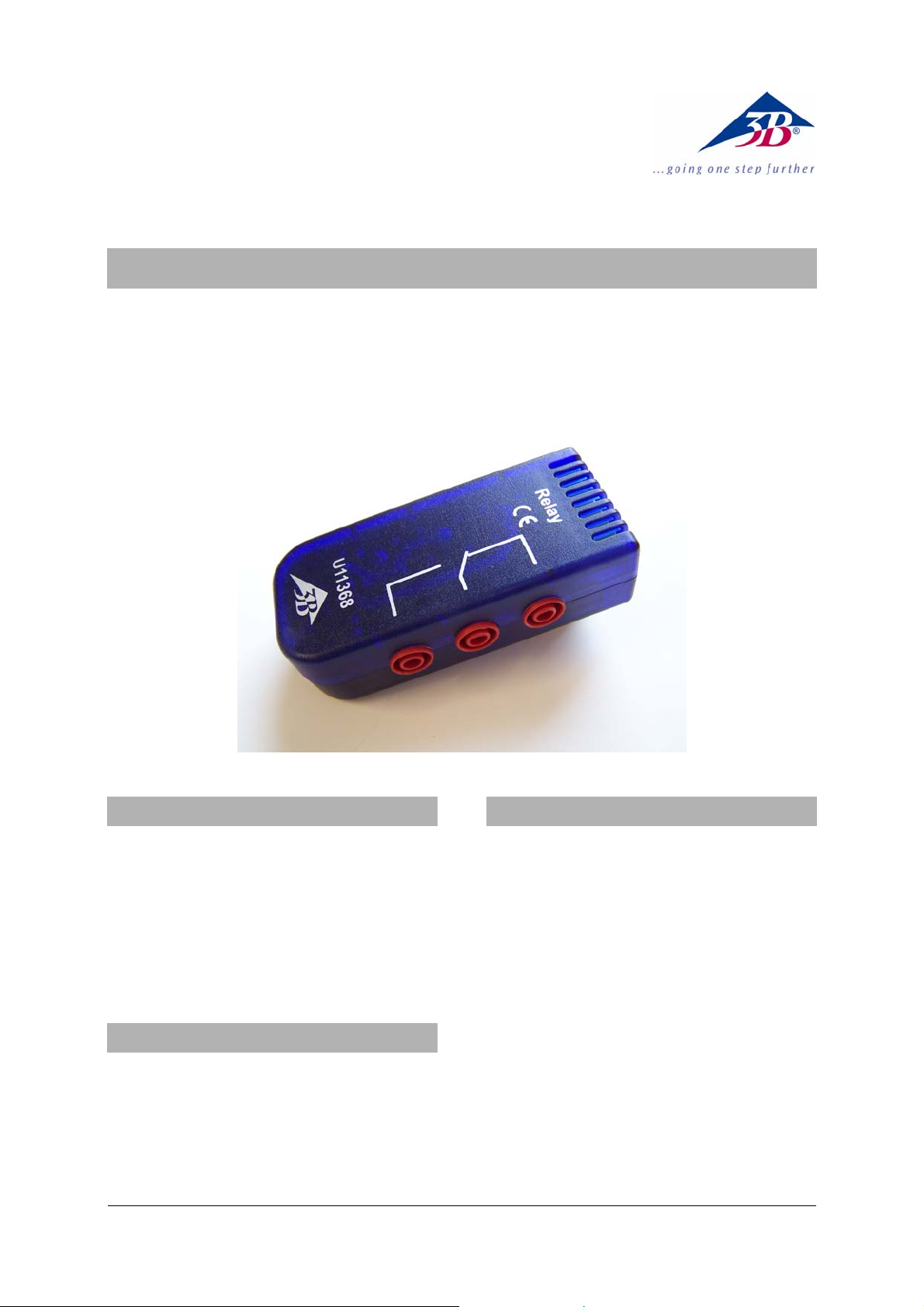
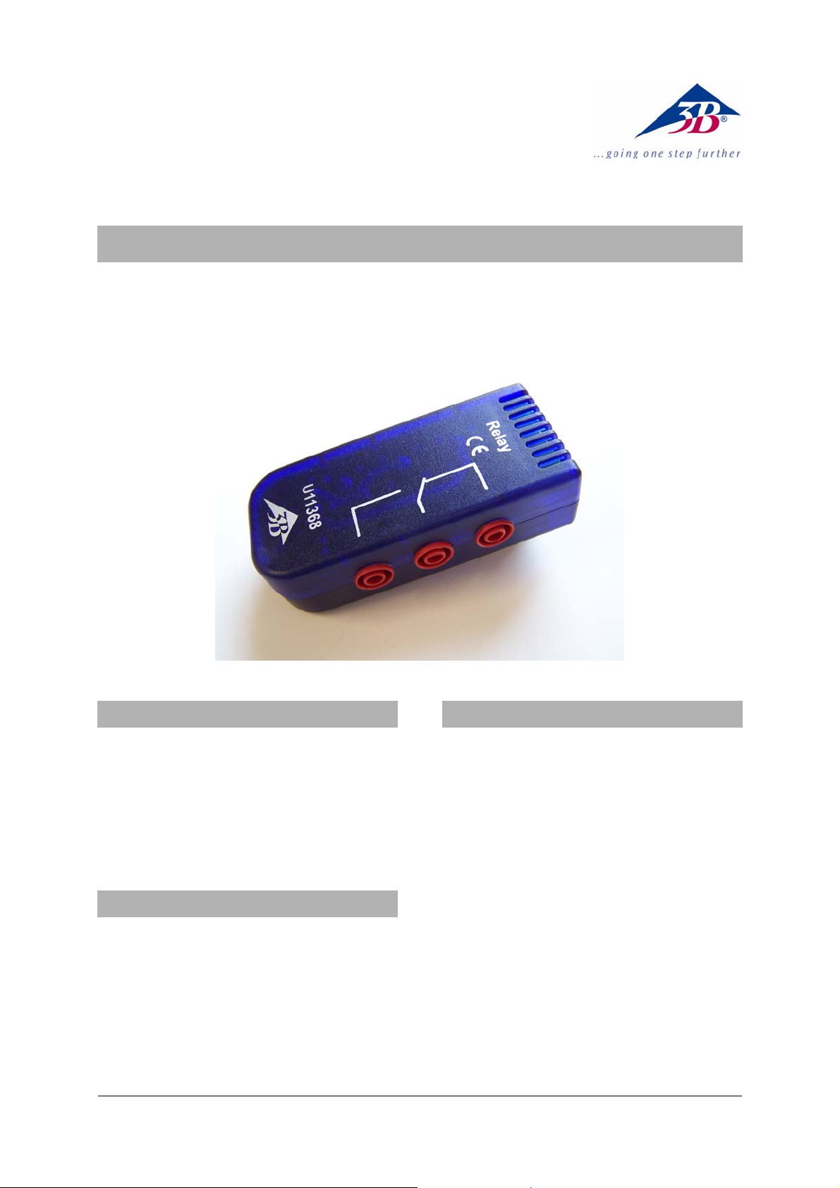
Relais U11368
Bedienungsanleitung
02/09 Hh
1. Sicherheitshinweise
• Die in den technischen Daten genannten ma-
ximalen Werte für die Schaltspannung, den
Schaltstrom und die Schaltleistung nicht überschreiten!
Es besteht Brandgefahr!
• Wegen einer möglichen Überwindung der
Potenzialtrennung keine Hochspannung mit
diesem Relais schalten!
2. Lieferumfang
1 Relais
1 miniDIN-Anschlusskabel 8-pin, 60 cm lang
3. Beschreibung
Das Relais dient zum Ereignis-bezogenen Ein- bzw.
Ausschalten von Komponenten, die elektrisch vom
Experimentieraufbau getrennt sind, z.B. Glühlampen, kleine bis mittelgroße Elektromotoren, Haltemagnete und elektromagnetisch betätigte Ventile.
Die Leistungsrelaisbox ist mit einem WechselKontaktsatz (1 Öffner / NC, 1 Schließer / NO,
1 Schaltkontakt / C) mit aufgedruckter Symbolik
ausgestattet und kann als Öffner bzw. als Schließer
verwendet werden.
Bei unerregter (stromloser) Relaisspule ist der Öffnerkontakt geschlossen.
Die Schaltkontakte bestehen aus einer hochwertigen Silberlegierung und sind auf 4 mmSicherheitsbuchsen herausgeführt.
Das Relais verfügt über eine sichere Potenzialtrennung nach VDE 0160 zwischen Spule und Kontaktsatz.
1
Page 2

4. Technische Daten
Schaltspannung: max. 250 V AC
max. 220 V DC
Schaltstrom: max. 6 A AC
max. 0,12 A DC
Schaltleistung: max. 1500 VA
min. 1 mW
5. Bedienung
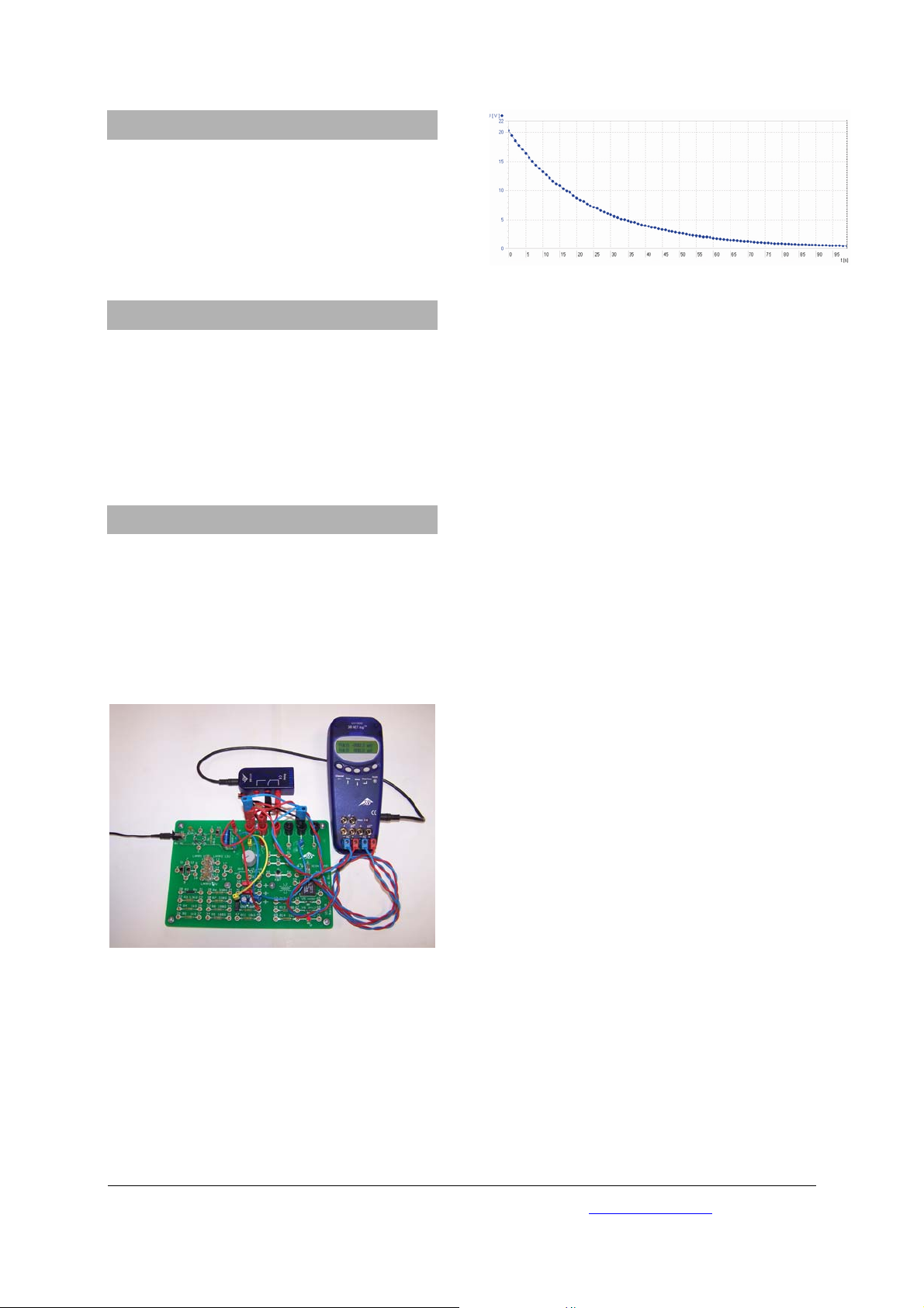
Fig. 2: Entladungskurve eines Kondensators
• Relais mit dem beigefügten miniDIN-Kabel an
der Buchse „Digital Outputs“ des 3B NETlog
TM
anstecken. Es reagiert auf den digitalen Ausgang A.
• Die weiteren elektrischen Verbindungen zum
Experimentieraufbau bevorzugt mit 4 mmSicherheitskabeln herstellen.
6. Versuchsbeispiel
Messung der Entladung eines Kondensators auf
dem Grundlagen-Experimentierboard
1 3B NETlog
TM
U11300
1 Relais U11368
1 Grundlagen-Experimentierboard U11380
Div. Experimentierkabel mit 2 mm- und 4mm-
Steckern
Fig. 1: Messung der Entladung eines Kondensators
• Die Verkabelung des Experiments und des
Relais der Anleitung des GrundlagenExperimentierboard U11380 entnehmen.
• Am 3B NETlog
TM
einen der beiden Analogeingänge A oder B wählen und aus der Bedienungsanleitung des Boards das Experiment für
die Kondensatorentladung nachvollziehen;
hier befinden sich alle erforderlichen Auswerteeinstellungen.
• Das Experiment durchführen und auswerten:
3B Scientific GmbH • Rudorffweg 8 • 21031 Hamburg • Deutschland • www.3bscientific.com
Technische Änderungen vorbehalten
© Copyright 2009 3B Scientific GmbH
Page 3
3B SCIENTIFIC® PHYSICS
Relay U11368
Instruction sheet
02/09 Hh
1. Safety instructions
• Do not exceed the maximal values specified for
the switching voltage, switching current and
the power rating specified in the technical data
section.
This constitutes a fire hazard.
• Do not connect this relay to high voltage since
this might break down the potential isolation.
2. Scope of delivery
1 Relay
1 Mini DIN connecting lead 8-pin, 60 cm length
3. Description
The relay is an event-triggered switch for switching
on or off components that are electrically isolated
from the experiment set-up. Examples of such
components include light bulbs, small to mediumsized electrical motors, holding magnets and electromagnetically operated valves.
The power relay box is equipped with a set of contacts (1 N/C contact, 1 N/O contact, 1 change-over
contact) with printed labels so that can be used as
an N/C or an N/O switch.
When the relay coil is inactive (when no current is
flowing), the N/C contact is closed.
The switch contacts consist of high-grade silver
alloy and are connected to 4-mm safety sockets.
The relay is equipped with safe potential isolation
between the coil and the contacts in conformance
with the VDE 160 standard.
1
Page 4
4. Technical data
Switching voltage: 250 V AC
220V DC max.
Switching current: 6A AC
0.12 A DC max.
Power rating: 1500 VA max.
1 mW min.
5. Operation
Fig. 2: Discharge curve of a capacitor
• Connect the relay to the “Digital Outputs”
socket of the 3B NETlog
TM
equipment using the
supplied mini DIN lead. It responds to digital
output A.
• Preferably use 4-mm safety leads for the re-
maining electrical connections to the experiment set-up.
6. Sample experiment
Measuring the discharge of a capacitor with the
basic experiment board
1 3B NETlog
TM
U11300
1 Relay U11368
1 Basic experiment board U11380
Various experiment leads with 2-mm and 4-mm
plugs
Fig. 1: Measuring the discharge of a capacitor
• Consult the instructions for the basic experi-
ment board U11380 for the electrical connections between the relay and the experiment.
• Select one of the analog inputs (A or B) on the
3B NETlog
TM
module and follow the instructions
for the board regarding the experiment on capacitor discharge. All necessary output value
settings are specified here.
• Conduct and analyse the experiment.
3B Scientific GmbH • Rudorffweg 8 • 21031 Hamburg • Germany • www.3bscientific.com
Subject to technical amendments
© Copyright 2009 3B Scientific GmbH
Page 5

3B SCIENTIFIC® PHYSICS
Relais U11368
Instructions d’utilisation
02/09 Hh
1. Consignes de sécurité
• Il est interdit de dépasser les valeurs maxima-
les précisées dans les caractéristiques techniques pour la tension de commutation, le courant de commutation et la puissance de coupure.
Risque d'incendie !
• En raison d'une éventuelle pénétration de la
coupure de potentiel, n'utilisez pas de haute
tension avec ce relais !
2. Matériel fourni
1 relais
1 câble de connexion mini-Din à 8 broches, 60 cm
de long
3. Description
Le relais permet la mise en et hors service de composants qui sont coupés électriquement du montage expérimental, par ex. des lampes à incandescence, des moteurs électriques de petite et
moyenne taille, des aimants de maintien et des
soupapes électromagnétiques.
La boîte à relais de puissance est équipée d'un jeu
de contacts inverseurs (1 contact de repos / NC, 1
contact de travail / NO, 1 contact de commutation /
C) dont les symboles sont imprimés sur la boîte, et
peut servir de contact de repos ou de travail.
Lorsque la bobine du relais n'est pas excitée (hors
tension), le contact de repos est fermé.
Constitués d'un alliage d'argent de grande qualité,
les contacts de commutation sont terminés par des
douilles de sécurité de 4 mm.
Le relais dispose d'une séparation sûre du potentiel
d'après VDE 0160 entre la bobine et le jeu de
contacts.
1
Page 6

4. Caractéristiques techniques
Tension de commutation : max. 250 V CA
max. 220 V CC
Courant de commutation : max. 6 A CA
max. 0,12 A CC
Puissance de coupure : max. 1 500 VA
min. 1 mW
5. Manipulation
Fig. 2 : Courbe de décharge d'un condensateur
• Branchez le relais avec le câble mini-Din fourni
à la douille « Digital Outputs » du 3B NETlog
Il réagit à la sortie numérique A.
•
Établissez les autres liaisons électriques vers le
TM
montage expérimental de préférence avec des
câbles de sécurité de 4 mm.
6. Exemples d'expérience
Mesure de la décharge d'un condensateur sur la
plaque d'expérimentation de base
1 3B NETlog
TM
U11300
1 relais U11368
1 plaque d'expérimentation de base U11380
Div. câbles d'expérimentation avec fiches de 2 mm
et 4 mm
.
Fig. 1 : Mesure de la décharge d'un condensateur
• Pour le câblage de l'expérience et du relais,
consultez le mode d'emploi de la plaque d'expérimentation U11380.
• Sur le 3B NETlog
TM
, sélectionnez l'une des deux
entrées analogiques A ou B et consultez le
mode d'emploi de la plaque pour retrouver
tous les réglages requis pour l'expérience sur
la décharge d'un condensateur.
• Réalisez l'expérience et évaluez-la :
3B Scientific GmbH • Rudorffweg 8 • 21031 Hamburg • Allemagne ▪ www.3bscientific.com
Sous réserve de modifications techniques
© Copyright 2009 3B Scientific GmbH
Page 7

3B SCIENTIFIC® PHYSICS
Relè U11368
Istruzioni per l'uso
02/09 Hh
1. Norme di sicurezza
• Non superare i valori massimi indicati nei dati
tecnici per tensione di commutazione, corrente
di commutazione e potenza di commutazione!
Pericolo di incendio!
• A causa del possibile superamento della
separazione di potenziale, non collegare
questo relè all'alta tensione!
2. Fornitura
1 relè
1 cavo di collegamento miniDIN da 8 pin, lungh.
60 cm
3. Descrizione
Il relè serve per l'attivazione e/o la disattivazione
ad evento di componenti elettricamente separati
dalla struttura sperimentale, ad es. lampadine,
motori elettrici di piccole e medie dimensioni,
magneti di chiusura e valvole ad azionamento
elettromagnetico.
La scatola del relè di potenza è dotata di un set di
contatti di scambio (1 contatto di apertura / NC,
1 contatto di chiusura / NO, 1 contatto di
chiusura / C) con simboli impressi e può essere
utilizzata come contatto di apertura o chiusura.
In caso di bobina del relè non eccitata (senza
corrente) il contatto di apertura è chiuso.
I contatti di commutazione consistono in una lega
di argento di alta qualità e vengono fatti
fuoriuscire da jack di sicurezza d 4 mm.
Il relè è dotato di una separazione di potenziale
sicura secondo VDE 0160 tra la bobina e il set di
contatti.
1
Page 8

4. Dati tecnici
Tensione di commutazione: max. 250 V AC
max. 220 V DC
Corrente di commutazione: max. 6 A AC
max. 0,12 A DC
Potenza di commutazione: max. 1500 VA
min. 1 mW
5. Comandi
• Collegare il relè alla presa "Digital Outputs" di
3B NETlog
dotazione. Esso reagisce all'uscita digitale A.
•
Realizzare gli altri collegamenti elettrici con la
TM
con il cavo miniDIN fornito in
struttura sperimentale utilizzando
preferibilmente cavi di sicurezza da 4 mm.
6. Esperimento di esempio
Misurazione della scarica di un condensatore
sulla scheda per esperimenti di base
1 3B NETlog
TM
U11300
1 relè U11368
1 scheda per esperimenti di base U11380
Vari cavi per esperimenti con spinotto da 2 mm e 4 mm
Fig. 2: Curva di scarica di un condensatore
Fig. 1: Misurazione della scarica di un condensatore
• Per il cablaggio dell'esperimento e del relè,
fare riferimento alle istruzioni della scheda per
esperimenti di base U11380.
• Scegliere su 3B NETlog
TM
uno dei due ingressi
analogici A o B e riprodurre l'esperimento per
la scarica del condensatore seguendo le
istruzioni per l'uso della scheda; qui sono
presenti tutte le impostazioni necessarie per la
valutazione.
• Eseguire l’esperimento e procedere alla
valutazione:
3B Scientific GmbH • Rudorffweg 8 • 21031 Amburgo• Germania• www.3bscientific.com
Con riserva di modifiche tecniche
© Copyright 2009 3B Scientific GmbH
Page 9

3B SCIENTIFIC® PHYSICS
Relé U11368
Instrucciones de uso
02/09 Hh
1. Advertencias de seguridad
• ¡No se deben sobrepasar los valores máximos
indicados en los datos técnicos para la
tensión, la corriente y la potencia de
conmutación!
¡Se corre el peligro de incendio!
• ¡Debido a la posible supresión de la separación
galvánica no se debe conectar una alta tensión
con este relé!
2. Volumen de entrega
1 Relé
1 Cable de conexión miniDIN de 8 pines y 60 cm de
largo
3. Descripción
El relé sirve para conexión y desconexión, referida
a un evento, de componentes que se encuentran
separadas galvánicamente dentro de un montaje
experimental, p.ej. bombillas incandescentes,
motores eléctricos pequeños y medianos, imanes
de sujeción y válvulas de mando electromagnético.
La caja del relé de potencia está dotada de un
juego de contactos de conmutación y conexión (1
de apertura/NC, 1 de cierre/NO, 1 de
conmutación/C) con símbolos impresos y puede ser
utilizada como elemento de apertura o de cierre.
En la condición de reposo de la bobina de relé (sin
corriente) el contacto de apertura se encuentra
cerrado
Los contactos de conmutación están compuestos de
aleación de plata y se sacan hacia afuera por
medio de casquillos de seguridad de 4 mm.
El relé dispone de una separación galvánica segura
entre la bobina y el juego de contactos, satisfaciendo
la normativa VDE 0160 resp. NE 59178
1
Page 10

4. Datos técnicos
Tensión de conmutación: max. 250 V CA
max. 220 V CC
Corriente de conmutación: max. 6 CA
max. 0,12 A CC
Potencia de conmutación: max. 1500 VA
min. 1 mW
5. Manejo
• Se enchufa el relé en el casquillo “Digital
Outputs“ del 3B NETlog
TM
con el cable miniDIN
que acompaña a la unidad. Éste reacciona al
estado de la salida digital A..
• Las siguientes conexiones eléctricas para el
montaje experimental se realizan
preferiblemente con cables de seguridad de 4
mm.
6. Experimento ejemplar
Medición de la descarga de un condensador en
la placa de experimentación
1 3B NETlog
TM
U11300
1 Relé U11368
1 Placa de experimentación básica U11380
Diversos cables de experimentación con clavijas de
2 mm y 4 mm.
los ajustes necesarios para la evaluación el
experimento.
• Se realiza y evalúa el experimento:
Fig. 2: Curva de descarga de un condensador
Fig. 1: Medición de la descarga de un condensador
• El cableado del experimento y del relé se toma
de las instrucciones de la placa de
experimentación básica U11380.
• Se selecciona una de las entradas analógicas A
o B del 3B NETlog
TM
y se sigue el experimento
de las instrucciones de uso de la placa para la
descarga de un condensador. En las
instrucciones se encuentran indicados todos
3B Scientific GmbH • Rudorffweg 8 • 21031 Hamburgo • Alemanha • www.3bscientific.com
Sob reserva de alterações técnicas
© Copyright 2008 3B Scientific GmbH
Page 11

3B SCIENTIFIC® PHYSICS
Relê U11368
Instruções para o uso
02/09 Hh
1. Indicações de segurança
• Não ultrapassar os valores máximos de tensão
de circuito, de corrente de circuito e de
desempenho indicados nos dados técnicos!
Há perigo de incêndio!
• Por causa de uma possível passagem da
separação de potenciais, não conectar alta
tensão neste relê!
2. Fornecimento
1 relê
1 cabo de conexão miniDIN de 8-pin, 60 cm de
comprimento
3. Descrição
O relê serve para desligar/ligar componentes em
função de um evento que estejam independentes
eletricamente da montagem da experiência, por
exemplo, lâmpadas incandescentes, pequenos a
médios motores elétricos, ímãs de sustentação e
válvulas eletromagnéticas.
A caixa de relê de desempenho está equipada de
jogo de contatos alternados (1 abridor / NC,
1 fecho / NO, 1 contato / C) com símbolos impressos
e pode ser utilizada como abridor ou como fecho.
No caso da bobina do relê estar sem corrente, o
contato de abertura fica fechado.
Os contatos de conexão estão feitos de uma liga de
prata de alta qualidade e estão ligadas a
conectores de segurança de 4 mm.
O relê dispõe de uma separação de potenciais
segura conforme VDE 0160 entre a bobina e o jogo
de contatos.
1
Page 12

4. Dados técnicos
Tensão de circuito: máx. 250 V AC
máx. 220 V DC
Corrente de circuito: máx. 6 A AC
máx. 0,12 A DC
Desempenho de circuito: máx. 1500 VA
mín. 1 mW
5. Utilização
• Ligar o relê com o cabo miniDIN incluído no
fornecimento no conector „Digital Outputs“ do
3B NETlog
• Efetuar as outras conexões elétricas para a
TM
. Há reação na saída digital A.
montagem da experiência de preferência com
cabos de segurança de 4 mm.
6. Exemplo de experiência
Medição da descarga de um condensador na
placa de experimentação básica
1 3B NETlog
TM
U11300
1 Relê U11368
1 placa de experimentação básica U11380
Div. cabos de experiências com conectores de
2 mm e 4mm
Fig. 2: curva de descarga de um condensador
Fig. 1: medição da descarga de um condensador
• As conexões da experiência e do relê estão
descritas no manual de instruções do placa de
experimentação básica U11380.
• Escolher uma das entradas analógicas A ou B
no 3B NETlog
TM
e seguir as instruções do
manual de instruções da placa na parte
relativa à descarga de condensador; aqui se
encontram todos os ajustes necessários para a
análise.
• Executar a experiência e analisar:
3B Scientific GmbH • Rudorffweg 8 • 21031 Hamburgo • Alemanha • www.3bscientific.com
Sob reserva de alterações técnicas
© Copyright 2009 3B Scientific GmbH
 Loading...