

Page 1
3B SCIENTIFIC® PHYSICS
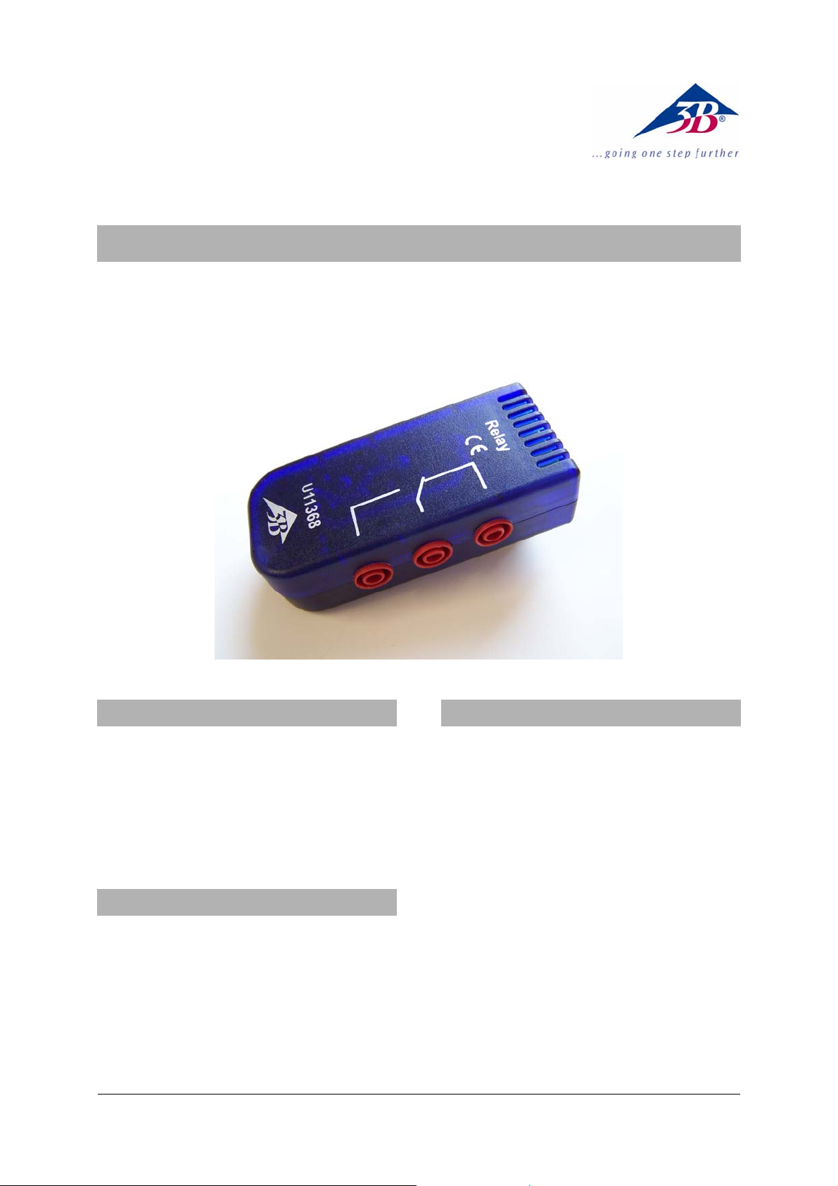
Relay U11368
Instruction sheet
02/09 Hh
1. Safety instructions
• Do not exceed the maximal values specified for
the switching voltage, switching current and
the power rating specified in the technical data
section.
This constitutes a fire hazard.
• Do not connect this relay to high voltage since
this might break down the potential isolation.
2. Scope of delivery
1 Relay
1 Mini DIN connecting lead 8-pin, 60 cm length
3. Description
The relay is an event-triggered switch for switching
on or off components that are electrically isolated
from the experiment set-up. Examples of such
components include light bulbs, small to mediumsized electrical motors, holding magnets and electromagnetically operated valves.
The power relay box is equipped with a set of contacts (1 N/C contact, 1 N/O contact, 1 change-over
contact) with printed labels so that can be used as
an N/C or an N/O switch.
When the relay coil is inactive (when no current is
flowing), the N/C contact is closed.
The switch contacts consist of high-grade silver
alloy and are connected to 4-mm safety sockets.
The relay is equipped with safe potential isolation
between the coil and the contacts in conformance
with the VDE 160 standard.
1
Page 2
4. Technical data
Switching voltage: 250 V AC
220V DC max.
Switching current: 6A AC
0.12 A DC max.
Power rating: 1500 VA max.
1 mW min.
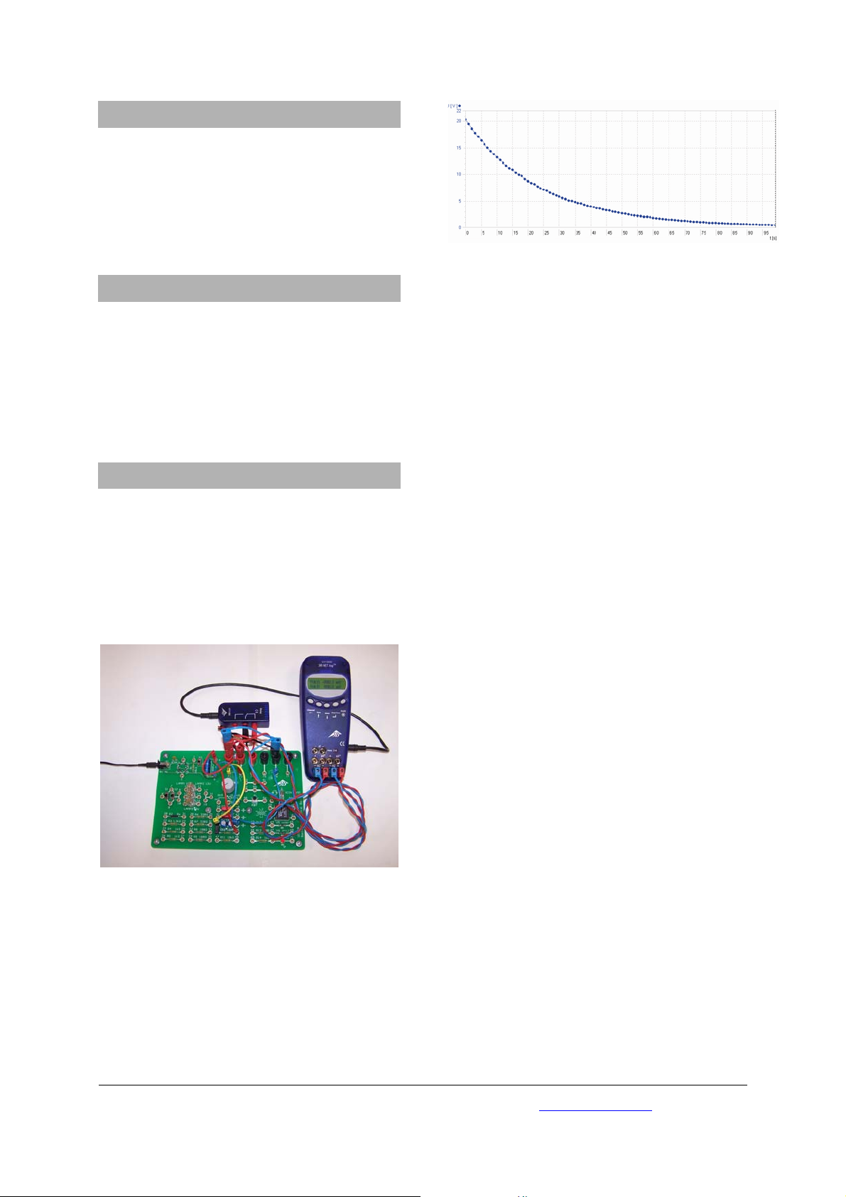
5. Operation
Fig. 2: Discharge curve of a capacitor
• Connect the relay to the “Digital Outputs”
socket of the 3B NETlog
TM
equipment using the
supplied mini DIN lead. It responds to digital
output A.
• Preferably use 4-mm safety leads for the re-
maining electrical connections to the experiment set-up.
6. Sample experiment
Measuring the discharge of a capacitor with the
basic experiment board
1 3B NETlog
TM
U11300
1 Relay U11368
1 Basic experiment board U11380
Various experiment leads with 2-mm and 4-mm
plugs
Fig. 1: Measuring the discharge of a capacitor
• Consult the instructions for the basic experi-
ment board U11380 for the electrical connections between the relay and the experiment.
• Select one of the analog inputs (A or B) on the
3B NETlog
TM
module and follow the instructions
for the board regarding the experiment on capacitor discharge. All necessary output value
settings are specified here.
• Conduct and analyse the experiment.
3B Scientific GmbH • Rudorffweg 8 • 21031 Hamburg • Germany • www.3bscientific.com
Subject to technical amendments
© Copyright 2009 3B Scientific GmbH
 Loading...