

Page 1
3B SCIENTIFIC
®
PHYSICS
Franck-Hertz Tube with Hg Filling and Heating Chamber (230 V, 50/60 Hz)
Franck-Hertz Tube with Hg Filling and Heating Chamber (115 V, 50/60 Hz)
1006795 (230 V, 50/60 Hz)
1006794 (115 V, 50/60 Hz)
Instruction sheet
06/12 ALF
1. Safety instructions
The apparatus conforms to the safety regulations for
electrical test, control and laboratory equipment as
specified in DIN EN 61010 Part 1. Its protection classification is deemed to be class I. It is intended for use in dry
rooms suitable for electrical equipment or installations.
Safe operation of the equipment is guaranteed, provided it is used correctly. However, there is no guarantee of safety if the equipment is used in an improper or careless manner. If it is deemed that the
equipment can no longer be operated without risk
(e.g. visible damage has occurred), the equipment
should be switched off immediately and secured
against any inadvertent use.
In schools and training institutions, operation of the
apparatus is to be responsibly supervised by trained
personnel.
• Before putting the equipment into operation, con-
firm it is compatible with the local mains voltage.
• Before setting up or starting any experiments,
check the apparatus for any damage.
• In the event of any malfunction/defect or visible
damage, switch off the equipment immediately
and secure it against any inadvertent use.
• The instrument may only be connected to the
mains via a socket that has an earth connection.
• Only trained electricians are permitted to open
up the apparatus’ housing.
Beware: Risk of burns! The viewing windows and the
walls of the heating chamber can reach temperatures of up to 300° C during operation.
• Set up the heating chamber on a heat-resistant
surface.
• When the heating chamber is in operation, do
not attempt to touch or move the apparatus.
Only move or transport the equipment by using
the insulated handle.
• Allow the apparatus to cool before dismantling
the experiment.
Beware: There is always a risk that glass can break
and cause injury.
• Use all six knurled screws to affix the front plate
to the heating chamber.
• Do not subject the tube to any mechanical
stress. Do not put kinks in any connecting leads.
The Franck-Hertz tube contains mercury.
• If the glass breaks and mercury escapes, make
sure to observe safety regulations relating to the
handling of mercury.
1
Page 2
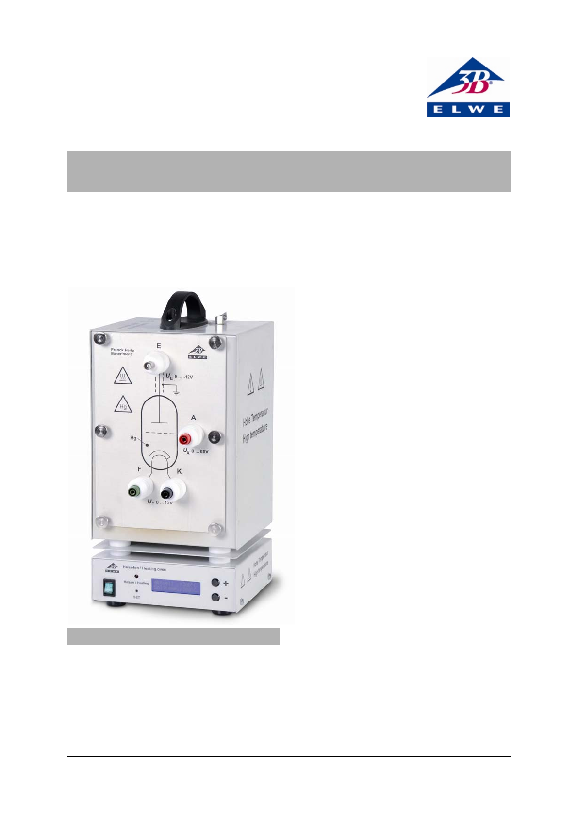
2. Description
The Franck-Hertz tube with its mercury filling is used
to demonstrate the quantised release of energy by
free electrons colliding with mercury atoms and to
determine that the excitation energy for the mercury
resonance line (6
1
S0 – 63P1) is 4.9 eV.
Franck-Hertz tube attached to front plate
The Franck-Hertz tube is a highly evacuated electron
tube containing mercury with its electrodes set up in
parallel planes. The electrodes consist of an indirectly
heated oxide cathode, an anode grid and a collector
electrode. In order to increase the likelihood of collisions, the distance between the anode and cathode
has been made large (8 mm) in comparison to the
mean free path in a mercury atmosphere (for a temperature of approx. 180°C). By contrast, the distance
between anode and collector is small. An earth ring is
located level with the anode grille to prevent disturbance due to background radiation. The tube is
mounted on the front plate of the heating chamber
and can be removed or exchanged. The front plate
also has ceramic-insulated sockets and a schematic
diagram of the tube. The Franck-Hertz tube is
mounted in such a way that the whole tube and its
connecting wires can all be maintained at constant
temperature. This is necessary because the density of
the mercury vapour is always determined at the coldest point of the tube. Leakage currents resulting from
radiation due to ion conduction in the hot glass walls
are prevented by a protective sintered alumina ring. A
fixed attenuating resistor (10 kΩ) is inserted between
the sockets for the accelerating voltage and for the
anode of the tube. This protects the tube in the event
of excessive voltage occurring due to arcing. The voltage drop across this resistor can be neglected when
measurements are being made.
Heating chamber
The heating chamber serves to establish the vapour
pressure inside the Franck-Hertz tube with its mercury
filling and helps you carry out experiments with a sodium fluorescence tube (1000913).
It consists of a powder-coated sheet steel casing with
two viewing windows. The front plate is attached via
six knurled screws. The chamber is heated via a tubular heating element in the chamber floor. Temperature measurement and regulation is carried via an
integrated micro-controller and a PT 100 thermocouple. A digital temperature display allows you to
read off the temperature set-point and the actual
temperature value. The “SET” button can be used to
toggle the display between ° Celsius and ° Fahrenheit. The “+/-” keys allow you to set the set-point for
the temperature in steps of 1 K. There is an opening
at the top with a spring clip for holding a thermometer and a thermally insulated carrying handle.
The apparatus 1006794 is for operation with a mains
voltage of 115 V (±10%), and the unit 1006795 is for
operation with a mains voltage of 230 V (±10%).
2.1 Scope of delivery
1 Franck-Hertz tube with mercury filling mounted
on front-plate
1 Heating chamber without front plate
1 Instruction sheet
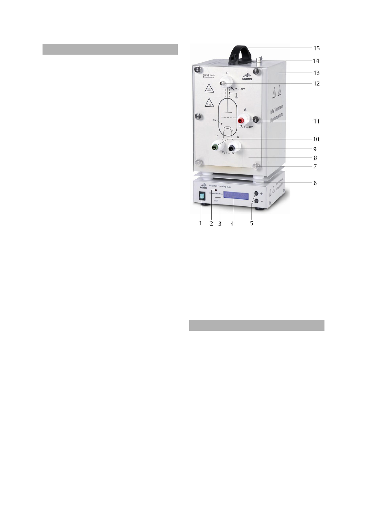
1 Power switch 2 Operating display
3 “SET” button 4 Display
5 “+/-” buttons 6 Thermal insulation
7 Knurled screws 8 Front plate with Franck-
8 Hertz tube attached (not
8 shown)
9 Cathode socket 10 Tube filament socket
11 Anode socket 12 BNC socket for signal
12 output
13 Heating chamber 14 Spring clip for thermometer
15 Handle
3. Technical data
Franck-Hertz tube
Filament: 4 to 12 V AC/DC
Grid voltage: 0 to 70 V
Bias voltage: 1.5 V approx.
Operating temperature: 200° C approx.
Tube dimensions: 130 mm x 26 mm diam.
Weight: 380 g approx.
Heating chamber
Mains voltage: See back of case
Dimensions of front
opening: 230 x 160 mm² approx.
Heating power: 800 W (230 V, 50/60 Hz)
400 W (115 V, 50/60 Hz)
Maximum temperature: 300°C (230 V, 50/60 Hz)
250°C (115 V, 50/60 Hz)
Temperature constancy: ±1°C approx.
Dimensions: 335x180x165 mm³ approx.
Weight: 5.6 kg approx.
2
Page 3
4. Operation
The following equipment is also required to complete the experiment:
1 Power supply unit for F/H experiment (230 V, 50/60 Hz)
1012819
or
1 Power supply unit for F/H experiment (115 V, 50/60 Hz)
1012818
1 Analogue oscilloscope, 2x 30 MHz 1002727
1 HF Patch cord, 1 m 1002746
2 HF Patch cords, BNC/4 mm plug 1002748
Safety leads for experiments
• Place front plate of the open side of the heating
chamber and fix it in place with 6 knurled
screws.
• Turn off the heating chamber and the control
unit to begin with and turn all the knobs on the
control fully to the left.
• Do not apply a voltage to the tube when it is still
cold (the mercury inside may cause a short circuit).
• Connect terminals "A", "F" and "K" (refer to fig. 2).
• Connect terminal "E" of the Franck-Hertz tube to
the correct input on the control unit by means of
an BNC cable.
• Connect the “FH Signal U
control unit to the Y input of the oscilloscope
and terminal “U
• Turn on the heating chamber. Set a temperature
” to the X input.
X
-out” terminal of the
Y
of about 210° C and wait for the tube to warm
up (about 5 to 10 minutes).
• Turn on the control unit and the equipment
should enter ramp mode.
• Set a filament voltage of 6 - 7 V. The indirectly
heated cathode requires about 90 seconds to
warm up, once the voltage is applied.
• Set the minimum acceleration voltage to zero,
slowly increase the maximum acceleration voltage to 80 V.
• Do not, however, increase the accelerating volt-
age so much that self-discharge no longer occurs
inside the tube. Any ionisation due to collisions
will disrupt the curve.
• Set up the oscilloscope initially with settings of
x = 1 V/div and y = 1 V/div.
• Observe the emergence of the maxima in the
Franck-Hertz trace on the oscilloscope screen.
• Set up all the parameters, accelerating voltage,
cathode filament, bias voltage and amplitude so
that a trace with nicely delineated maxima and
minima is obtained.
The procedure as described so far is a general setting
procedure. Unavoidable differences resulting from
the manufacture of individual Frank-Hertz tubes
mean that the optimum parameters may differ from
tube to tube. The test report included with the tube
should give some idea of where good results may be
obtained for the tube in question.
The collector current displays regularly recurring,
equidistant maxima and minima that are independent of the accelerating voltage. The interval between
these peaks is 4.9 V. A contact potential of 2 V exists
between the anode and cathode of the tube, which is
why the first maximum only appears in the region of
7 V. The first maxima will be more obvious when the
temperature of the heating chamber is lower.
Evaluation of the Franck-Hertz curve:
To fully evaluate the Franck-Hertz curve, a digital
voltmeter is needed. This does not require that the
current of the electron beam be determined precisely. The oscilloscope screen should show the trace
of a Franck-Hertz curve featuring very clear maxima
and minima.
• Connect a digital voltmeter between the signal
output (U
• Press the “Man/Ramp” button and the display
) and the ground socket (refer to fig. 3).
X
will show “Man” to indicate manual mode.
• Turn the accelerating voltage knob all the way to
the left (UA = 0 V).
The display will show the accelerating voltages in
steps of 0.5 V. In order to obtain better test results, a
digital voltmeter can be connected between sockets
"A" and "K" in order to obtain a more accurate
measure of the accelerating voltage.
Note: The accelerating voltage is reduced by a factor
of 10 at the signal output (U
however, measures the full accelerating voltage
). The digital voltmeter,
X
between sockets “A” and “K”.
By gradually increasing the accelerating voltage at a
constant rate, the precise position of the maxima
and minima can be determined with the aid of the
digital voltmeter.
5. Care and maintenance
• Before cleaning the equipment, disconnect it
from its power supply.
• Use a soft, damp cloth to clean it.
6. Disposal
• The packaging should be
disposed of at local recycling points.
• Should you need to dis-
pose of the equipment itself, never throw it away
in normal domestic waste.
Local regulations for the
disposal of electrical
equipment will apply.
• If Frank-Hertz tubes are to
be disposed of, local regulations applying to the
disposal of mercury must
be followed.
3
Page 4

Fig. 1 Schematic of set up for measuring the Franck-Hertz curve for mercury (C cathode, G grid, A collector electrode)
E
A
F
FK
K
GA
+
-
Fig. 2: Experiment set-up for Franck-Hertz tube with Hg filling
E
E
X
Y
A
F
FK
K
GA
E
+
-
Fig. 3 Experiment set-up for Franck-Hertz tube with 2 digital voltmeters
4
X
Y
Page 5
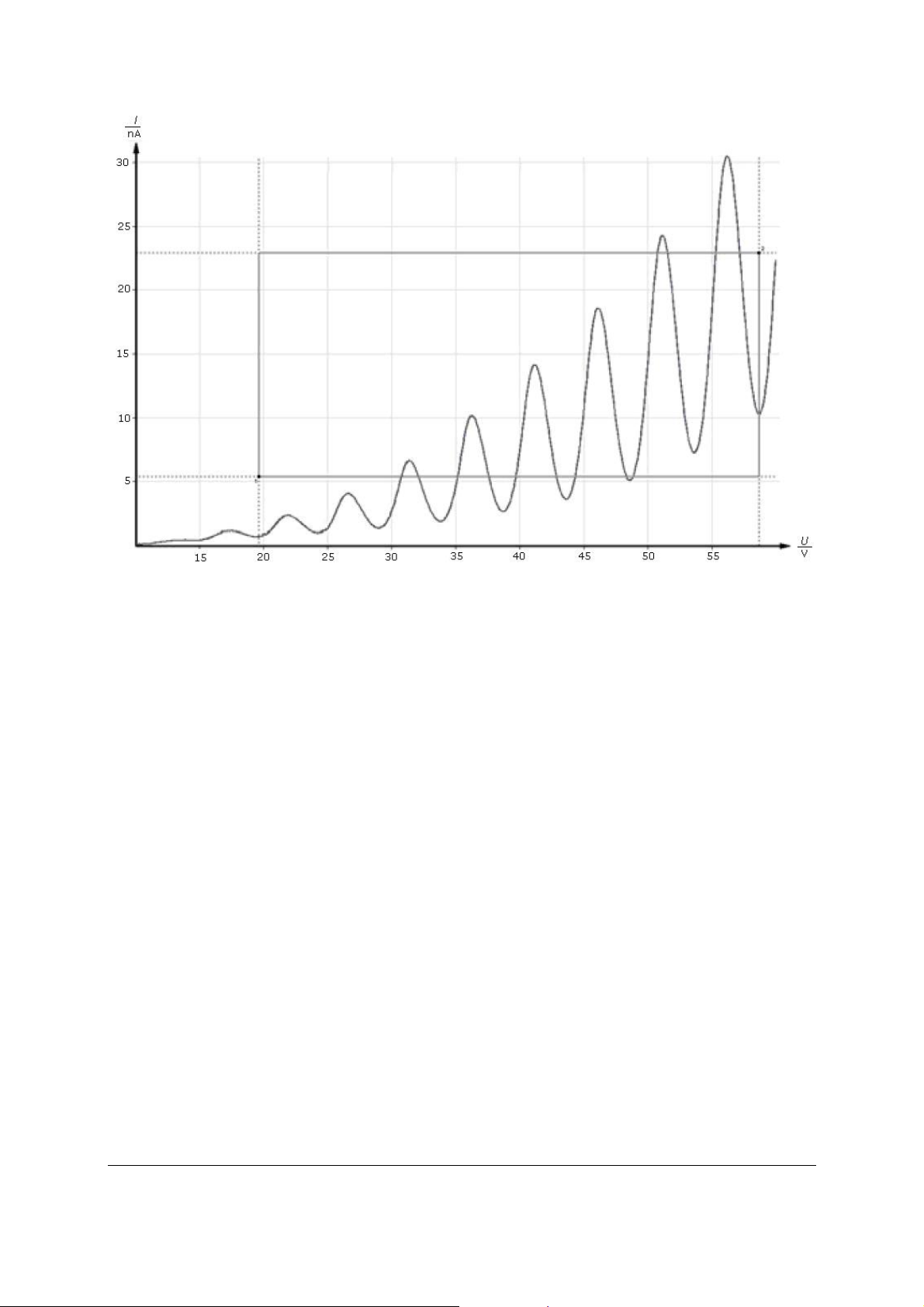
Fig. 4 Franck-Hertz curve
Elwe Didactic GmbH • Steinfelsstr. 5 • 08248 Klingenthal • Germany • www.elwedidactic.com
3B Scientific GmbH • Rudorffweg 8 • 21031 Hamburg • Germany • www.3bscientific.com
Subject to technical amendments
© Copyright 2012 3B Scientific GmbH
Page 6

 Loading...