

Page 1

3B SCIENTIFIC3B SCIENTIFIC
3B SCIENTIFIC®
3B SCIENTIFIC3B SCIENTIFIC
PHYSICSPHYSICS
PHYSICS
PHYSICSPHYSICS
®
Grundlagenversuche zur Optik auf der Optischen Bank U17150
Bedienungsanleitung
1/05 MH
Versuchsübersicht:
Versuch 1: Demonstration verschiedener Strahlen-
bündel
Versuch 2: Reflexion eines Lichtstrahls an einem
Planspiegel
Versuch 3: Reflexion eines Strahlenbündels an einem
Planspiegel
Versuch 4: Reflexion eines Strahlenbündels an einem
Hohl- bzw. Wölbspiegel
Versuch 5: Snellius’sches Brechungsgesetz
Versuch 6: Brechung an einer planparallelen Platte
Versuch 7: Brechung an einem Prisma
Versuch 8: Umkehrprisma
Versuch 9: Konkav und konvex Linsen
Versuch 10: Linsenformel und Vergrößerung
Versuch 11: Linsenformeln und Vergrößerung, virtu-
elle Abbildung
Versuch 12: Linsenformel und Vergrößerung, virtuel-
les Objekt
Versuch 13: Linsenfehler, sphärische Abberation 1
Versuch 14: Linsenfehler, sphärische Abberation 2
Versuch 15: Linsenfehler, chromatische Abberation
Versuch 16: Modell einer Camera obscura
Versuch 17: Modell eines Dia-Projektors
Versuch 18: Modell eines Mikroskops
Versuch 19: Modell eines astronomischen Fernrohrs
Versuch 20: Modell einer Fotokamera
Versuch 21: Modell eines holländischen Fernrohrs
Versuch 22: Polarisation, Modell eines Polarimeters
Versuch 23: Geradsichtprisma, Absorptionsspektrum
Versuch 24: Linienspektrum
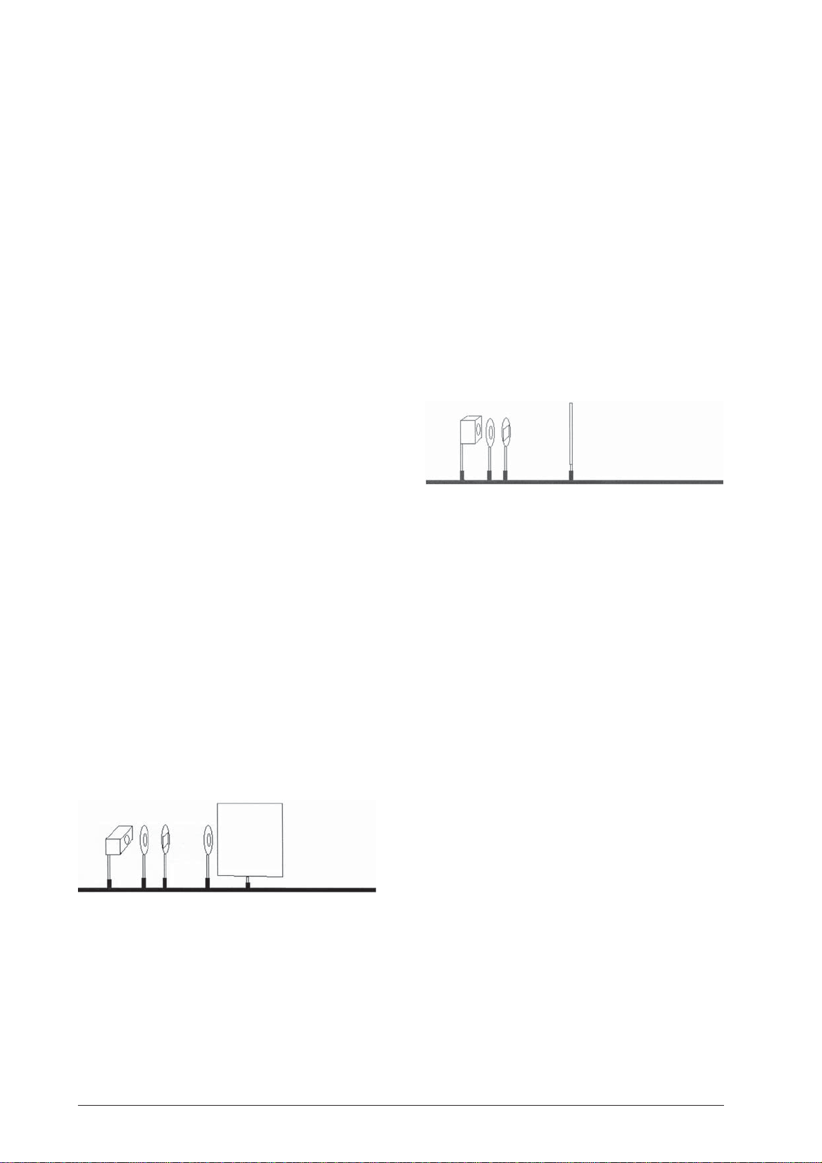
• Experimentierleuchte U17140
• Objekthalter auf Stiel U17000
• Fünffachspalt aus U17040
• Sammellinse f = +150 mm U17108
• Projektionsschirm U17125
• 3 Reiter 75 mm U17160
• 1 Reiter 30 mm U17161
• Stromversorgung Steckernetzgerät U13900
1.2 Aufbau
• Experimentierleuchte horizontal auf Position 10 cm
platzieren.
• Objekthalter mit Fünffachspalt horizontal auf Po-
sition 20 cm.
• Sammellinse auf Position 25 cm.
• Projektionsschirm auf kleinem Reiter.
1.3 Durchführung
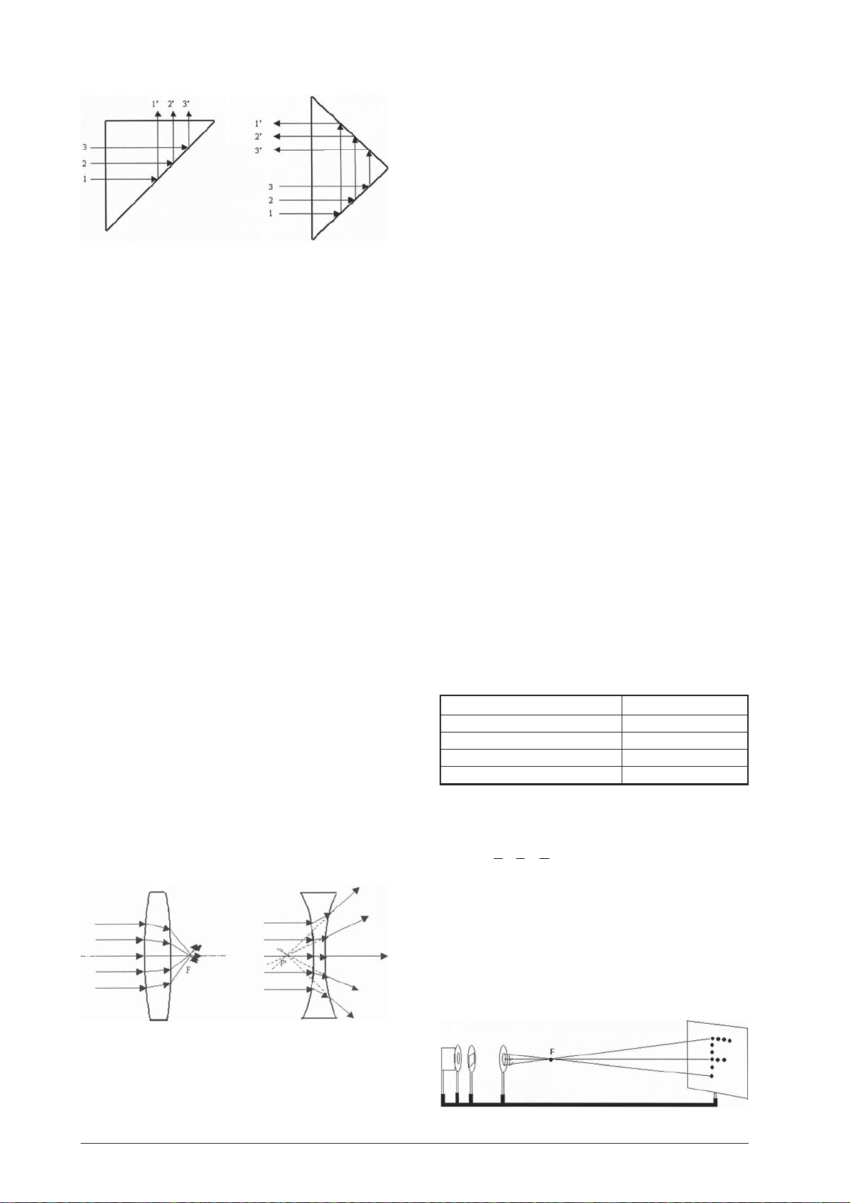
• Ohne Verwendung der Sammellinse ist das Strah-
lenbündel divergierend.
• Bei Einsatz der Sammellinse auf Position 25 cm
erhält man ein paralleles Strahlenbündel.
• Durch Verschieben der Sammellinse weg von der
Lichtquelle wird ein konvergierendes Strahlenbündel erzeugt.
1. Sicherheitshinweise
• Vorsicht! Leuchten erhitzen sich bei längerer Be-
triebsdauer.
• Optische Elemente nicht mit aggressiven Flüssig-
keiten oder Lösungsmitteln reinigen. Beschädigungsgefahr!
2. Versuchsbeispiele
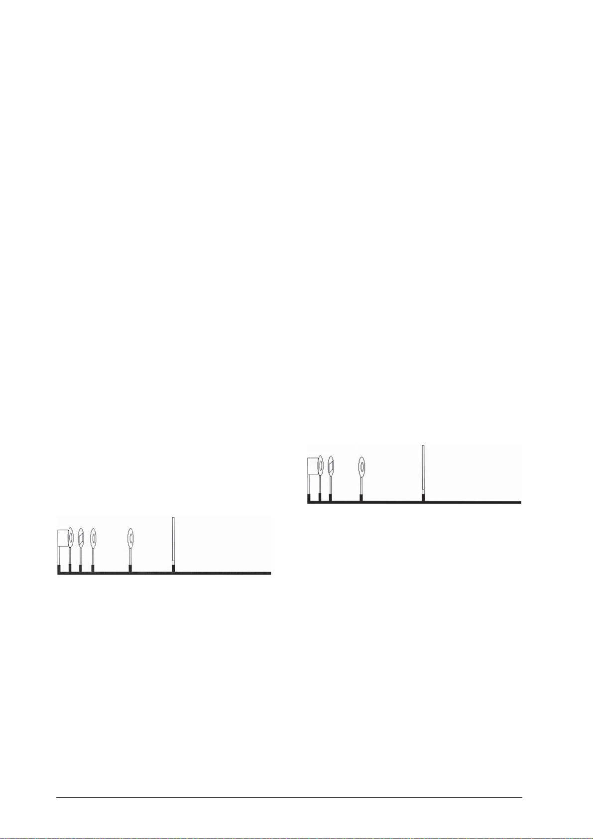
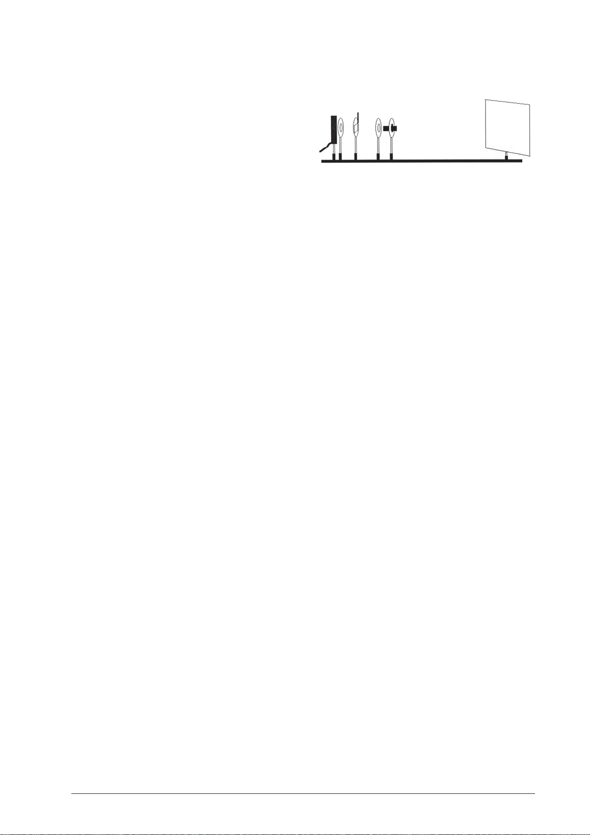
Versuch 1: Demonstration verschiedener Strahlenbündel
1.1 Geräte:
• Optische Bank U17150
Versuch 2: Reflexion eines Lichtstrahls an einem
Planspiegel
2.1 Geräte:
• Optische Bank U17150
• Experimentierleuchte U17140
• Objekthalter auf Stiel U17000
• Einfachspalt aus U17040
• Sammellinse f = +150 mm U17108
• Optische Scheibe U17128
• Planspiegel aus U17128
• 3 Reiter 75 mm U17160
• 1 Reiter 30 mm U17161
• Stromversorgung Steckernetzgerät U13900
Page 2
2.2 Aufbau
• Experimentierleuchte horizontal auf Position 10 cm
platzieren.
• Objekthalter mit Einfachspalt horizontal auf Posi-
tion 20 cm.
• Sammellinse auf Position 25 cm.
• Optische Scheibe mit Planspiegel auf kleinem Rei-
ter auf 40 cm.
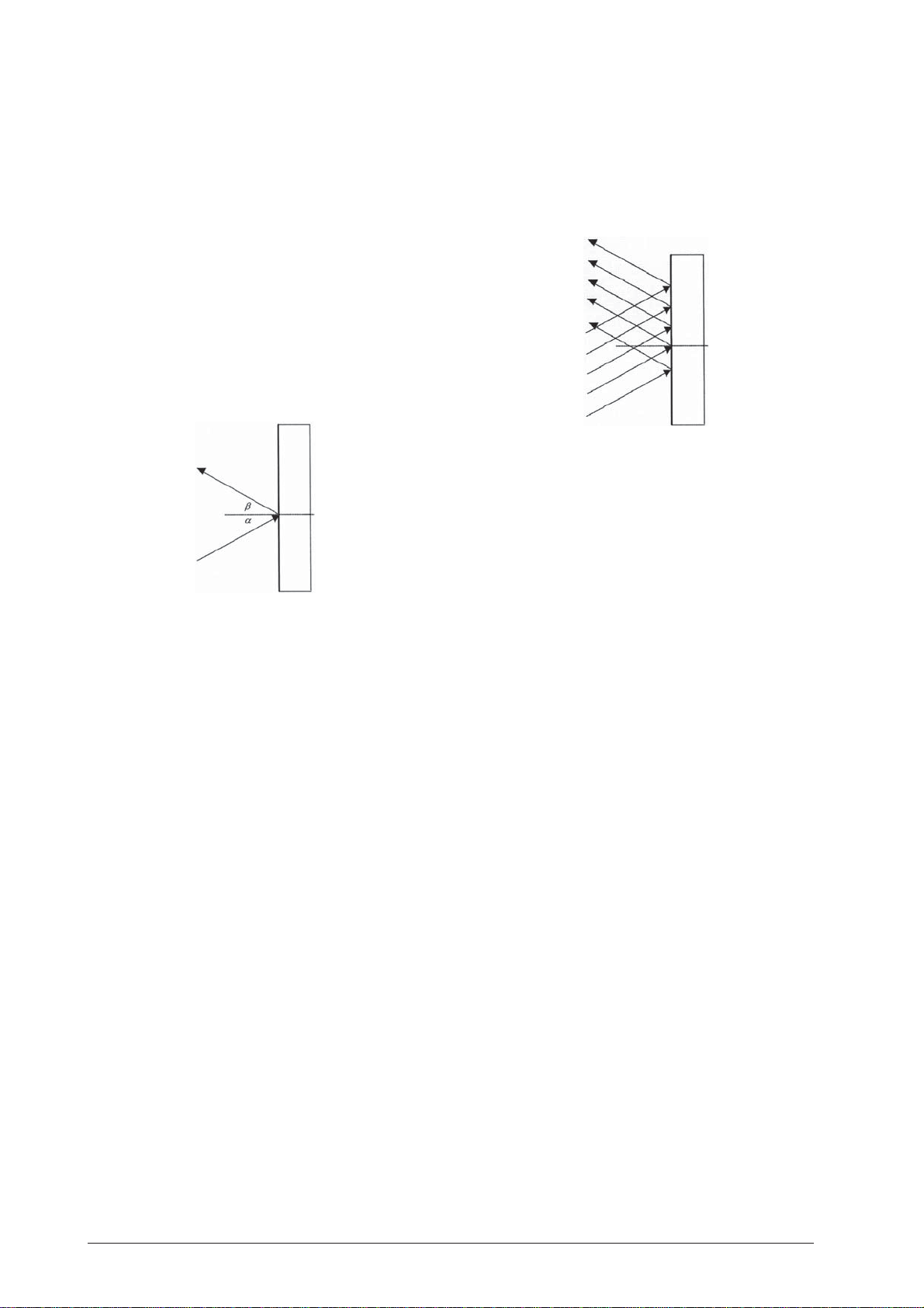
2.3 Durchführung
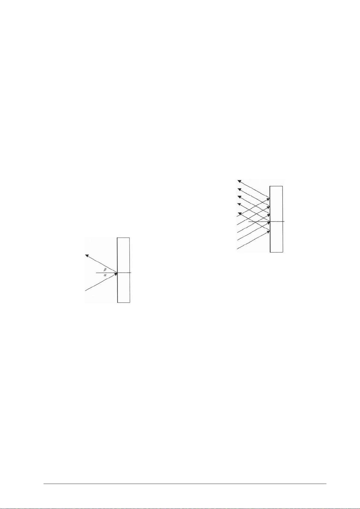
• Planspiegel auf der Optischen Scheibe auf der 90°-
90°-Linie befestigen.
• Höhe der Scheibe so einstellen, dass der einfallen-
de Lichtstrahl auf der 0°-Linie reflektiert wird.
• Durch Drehen der Scheibe Bestätigung des Reflexi-
onsgesetzes Einfallswinkel gleich Ausfallwinkel.
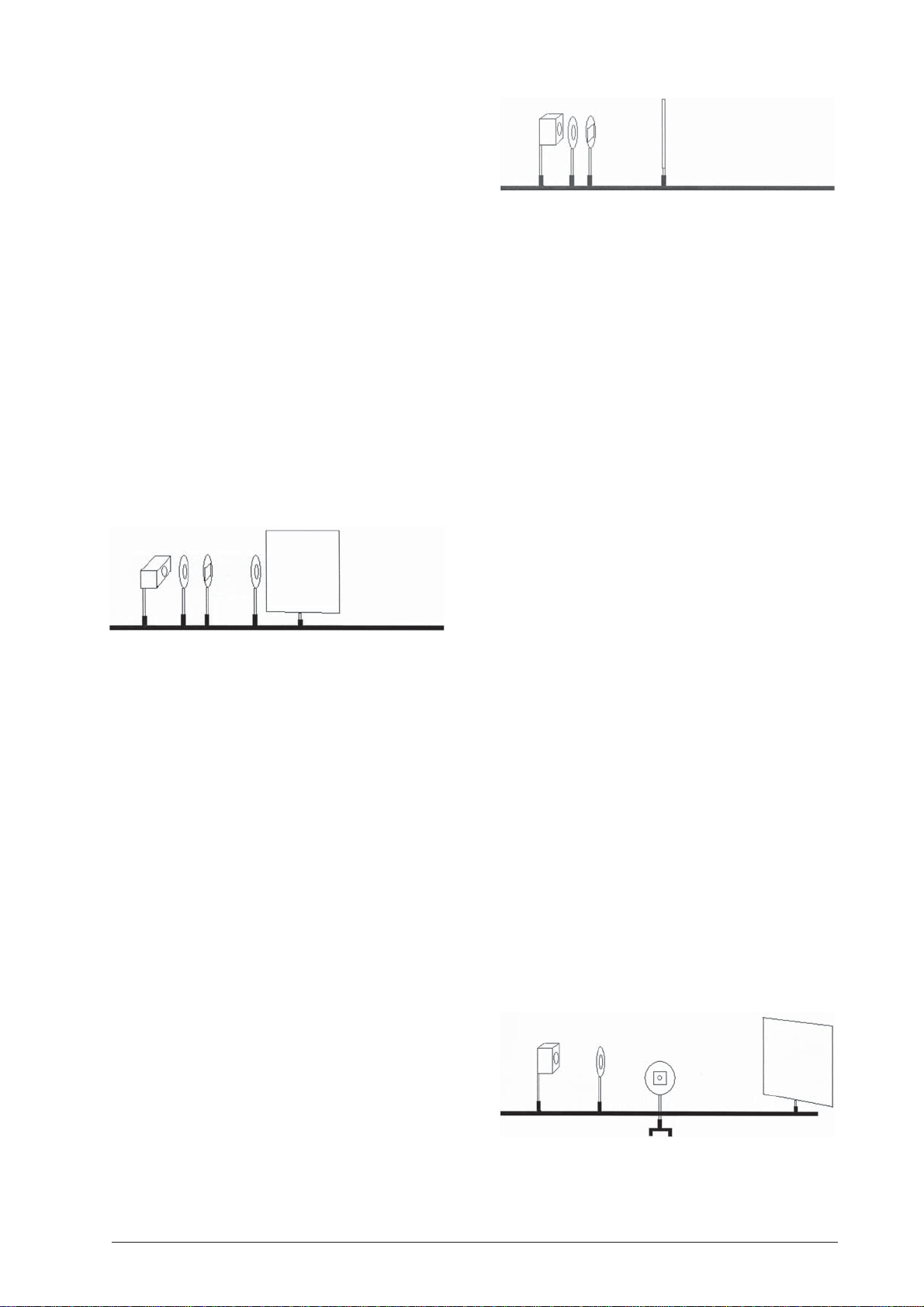
Versuch 3: Reflexion eines Strahlenbündels an
einem Planspiegel
3.1 Geräte:
• Optische Bank U17150
• Experimentierleuchte U17140
• Objekthalter auf Stiel U17000
• Fünffachspalt aus U17040
• Sammellinse f = +150 mm U17108
• Optische Scheibe U17128
• Planspiegel aus U17128
• 3 Reiter 75 mm U17160
• 1 Reiter 30 mm U17161
• Stromversorgung Steckernetzgerät U13900
• Durch Verschieben der Linse weg von der Lichtquel-
le kann gezeigt werden, dass ein konvergierendes
Strahlenbündel konvergierend reflektiert wird.
• Ohne Verwendung der Sammellinse lässt sich de-
monstrieren, dass ein divergierendes Strahlenbündel nach der Reflexion auch divergierend ist.
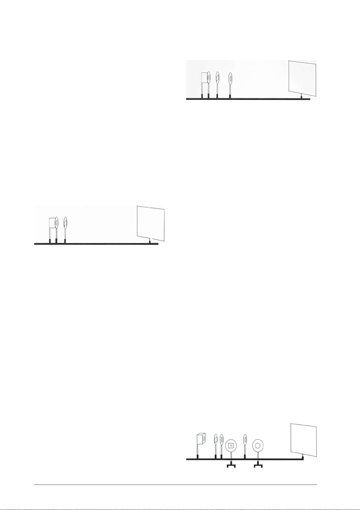
Versuch 4: Reflexion eines Strahlenbündels an
einem Hohl- bzw. Wölbspiegel
4.1 Geräte:
• Optische Bank U17150
• Experimentierleuchte U17140
• Objekthalter auf Stiel U17000
• Fünffachspalt aus U17040
• Sammellinse f = +150 mm U17108
• Optische Scheibe U17128
• Spiegel aus U17128
• 3 Reiter 75 mm U17160
• 1 Reiter 30 mm U17161
• Stromversorgung Steckernetzgerät U13900
4.2 Aufbau
• Experimentierleuchte horizontal auf Position 10 cm
platzieren.
• Objekthalter mit Fünffachspalt horizontal auf Po-
sition 20 cm.
• Sammellinse auf Position 25 cm.
• Optische Scheibe mit Konvexspiegel auf kleinem
Reiter auf 40 cm.
3.2 Aufbau
• Experimentierleuchte horizontal auf Position 10 cm
platzieren.
• Objekthalter mit Fünffachspalt horizontal auf Po-
sition 20 cm.
• Sammellinse auf Position 25 cm.
• Optische Scheibe mit Planspiegel auf kleinem Rei-
ter auf 40 cm.
3.3 Durchführung
• Planspiegel auf der Optischen Scheibe auf der 90°-
90°-Linie befestigen.
• Höhe der Scheibe so einstellen, dass der mittlere
Lichtstrahl auf der 0°-Linie verläuft und alle Strahlen in sich reflektiert werden.
• Durch Drehen der Scheibe wird gezeigt, dass ein
parallel einfallendes Strahlenbündel nach der Reflexion auch parallel ist.
4.3 Durchführung
• Hohlspiegel auf der Optischen Scheibe auf der 90°-
90°-Linie befestigen.
• Höhe der Scheibe so einstellen, dass der mittlere
Lichtstrahl auf der 0°-Linie verläuft und in sich reflektiert wird.
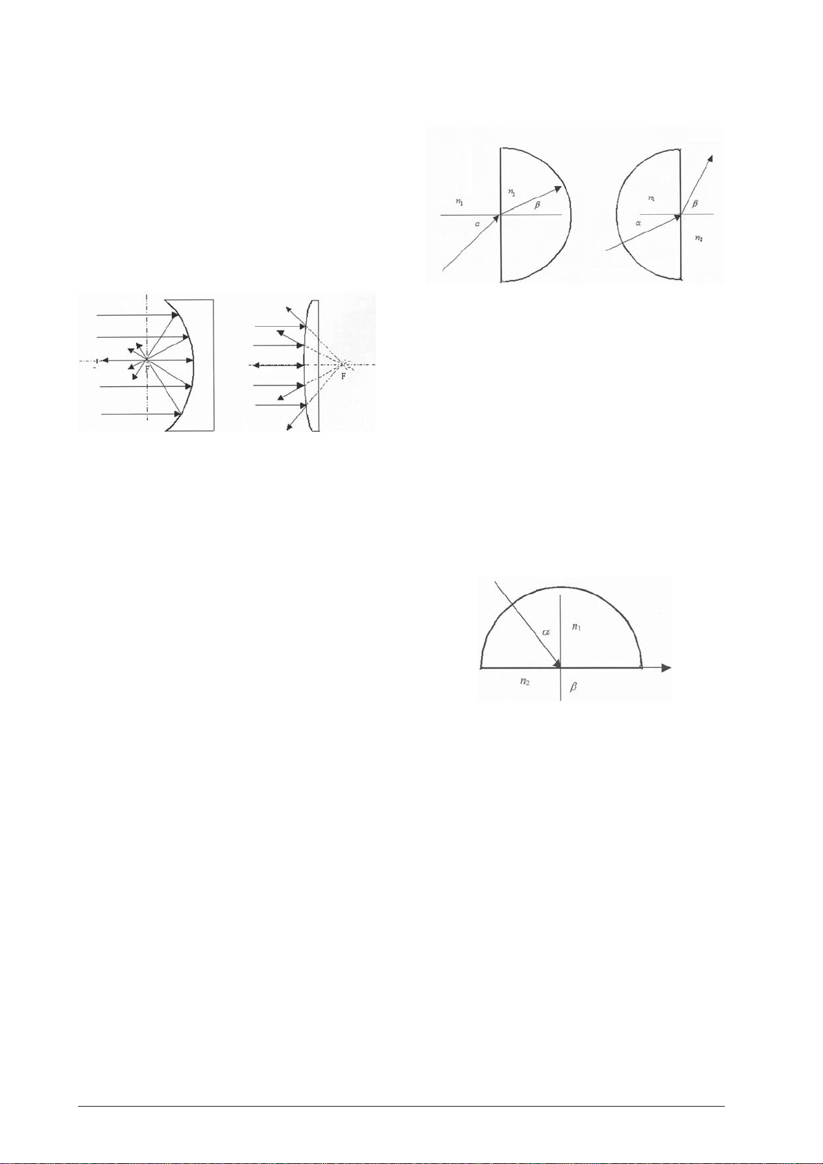
• Mittels der Linse ein paralleles Strahlenbündel er-
zeugen.
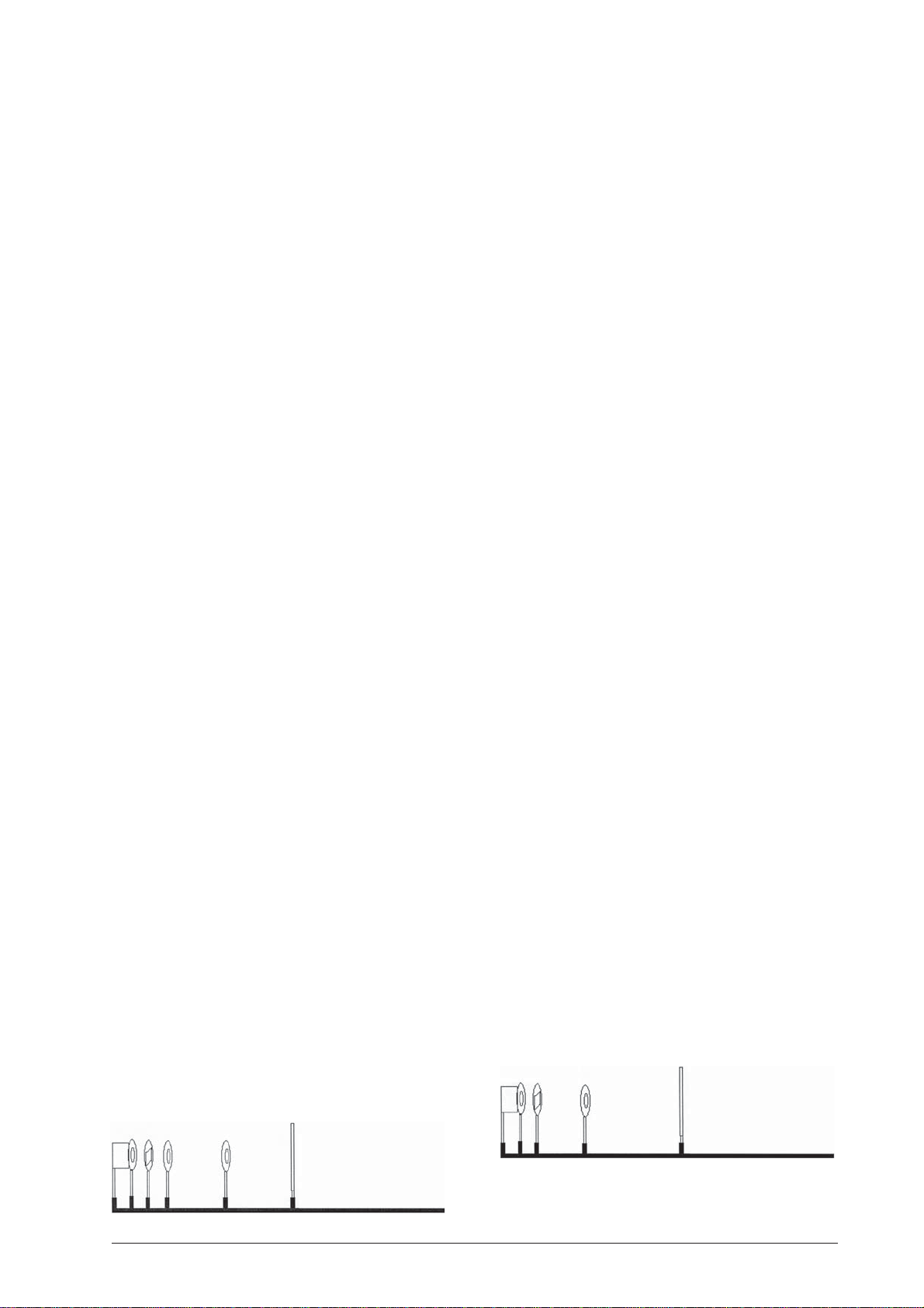
• Die einfallenden Strahlen werden so reflektiert,
dass sie sich in einem Punkt F treffen. Dieser Punkt
ist der Brennpunkt des Spiegels.
• Versuch mit konvergierenden und divergierenden
Strahlen wiederholen.
• Ergebnis: Ein Hohlspiegel wirkt konvergierend.
• Optische Scheibe um 180° drehen, so dass die ein-
fallenden Strahlen vom Wölbspiegel reflektiert
werden. Schritte wie oben durchführen.
2
Page 3
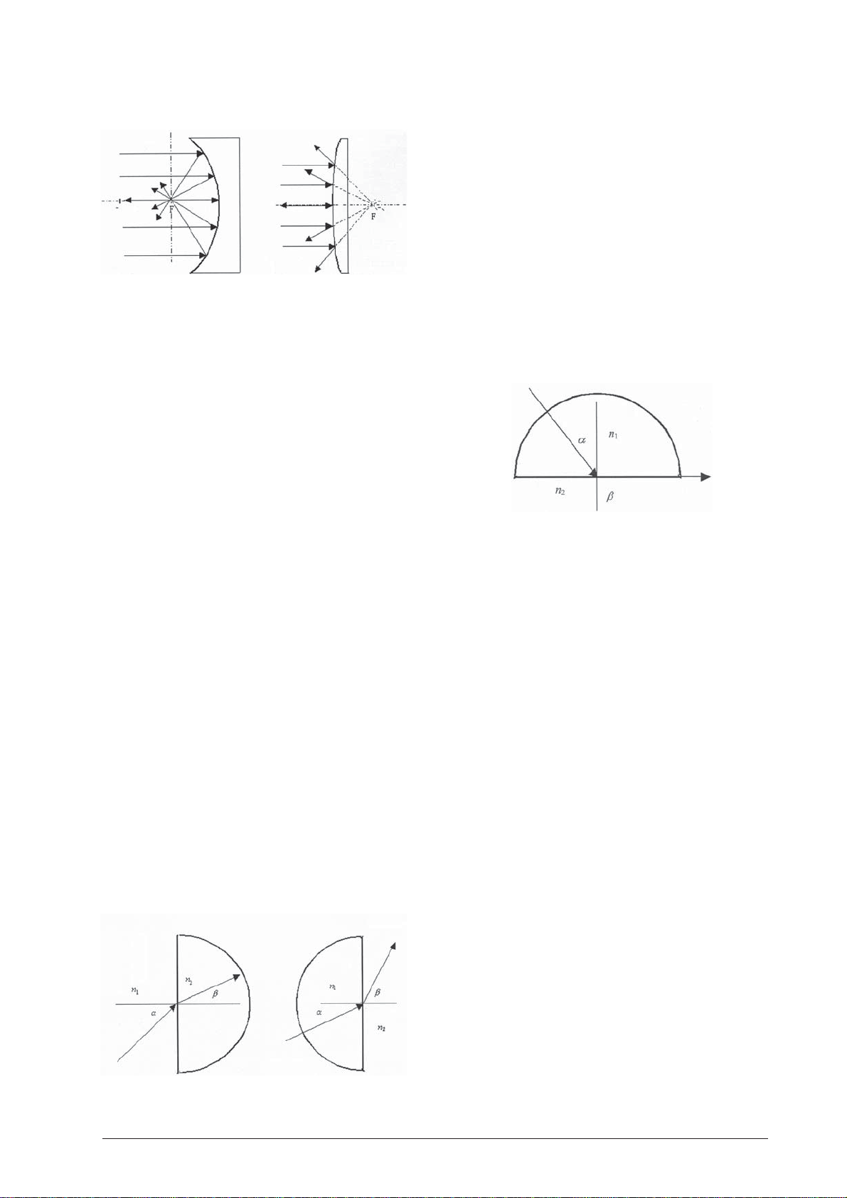
• Ein Wölbspiegel wirkt divergierend.
Versuch 5: Snellius’sches Brechungsgesetz
5.1 Geräte:
• Optische Bank U17150
• Experimentierleuchte U17140
• Objekthalter auf Stiel U17000
• Einfachspalt aus U17040
• Sammellinse f = +150 mm U17108
• Optische Scheibe U17128
• Halbkreiskörper aus U17128
• 3 Reiter 75 mm U17160
• 1 Reiter 30 mm U17161
• Stromversorgung Steckernetzgerät U13900
• Beim Übergang eines Lichtstrahls von einem Medi-
um mit dem Brechungsindex n1 in ein anderes
Medium mit dem Brechungsindex n2 wird seine
Richtungsänderung durch das Snellius’sche Brechungsgesetz bestimmt:
sin α / sin ß = konstant oder sin α / sin ß = n
α ist der Einfallswinkel in Medium n
und ß ist der
1
2 / n1
Brechungswinkel im Medium n2.
• Je größer der Einfallswinkel desto größer der Bre-
chungswinkel. Wenn n1 < n2 ist, existiert ein kritischer Winkel α. Der gebrochene Strahl liegt dann
an der Grenzfläche zwischen zwei Medien. Ist der
Einfallswinkel größer als der kritische Winkel, dann
gibt es keine Brechung mehr und das ganze Licht
wird reflektiert. In diesem Fall spricht man von
Totalreflexion.
5.2 Aufbau
• Experimentierleuchte horizontal auf Position 10 cm
platzieren.
• Objekthalter mit Einfachspalt horizontal auf Posi-
tion 20 cm.
• Sammellinse auf Position 25 cm.
• Optische Scheibe mit Halbkreiskörper auf kleinem
Reiter auf 40 cm.
5.3 Durchführung
• Halbkreiskörper so auf der Optischen Scheibe auf
der 90°-90°-Linie befestigen, dass die plane Seite
zur Lichtquelle weist.
• Höhe der Scheibe so einstellen, dass der einfallen-
de Lichtstrahl auf der 0°-Linie verläuft und genau
die Mitte des Halbkreiskörpers trifft. Der Lichtstrahl
verläuft dann ungebrochen auf der 0°-Linie.
• Durch Drehen der Scheibe wird der Lichtstrahl zum
Einfallslot hin gebrochen.
• Die Scheibe nun um 180° drehen, so dass die ge-
wölbte Scheibe zur Lichtquelle zeigt. Der Lichtstrahl
wird nun vom Ausfallslot weg gebrochen.
Versuch 6: Brechung an einer planparallelen
Platte
6.1 Geräte:
• Optische Bank U17150
• Experimentierleuchte U17140
• Objekthalter auf Stiel U17000
• Einfachspalt aus U17040
• Sammellinse f = +150 mm U17108
• Optische Scheibe U17128
• Trapezkörper aus U17128
• 3 Reiter 75 mm U17160
• 1 Reiter 30 mm U17161
• Stromversorgung Steckernetzgerät U13900
6.2 Aufbau
• Experimentierleuchte horizontal auf Position 5 cm
platzieren.
• Objekthalter mit Einfachspalt horizontal auf Posi-
tion 20 cm.
• Sammellinse auf Position 25 cm.
• Optische Scheibe mit Trapezkörper auf kleinem
Reiter auf 40 cm.
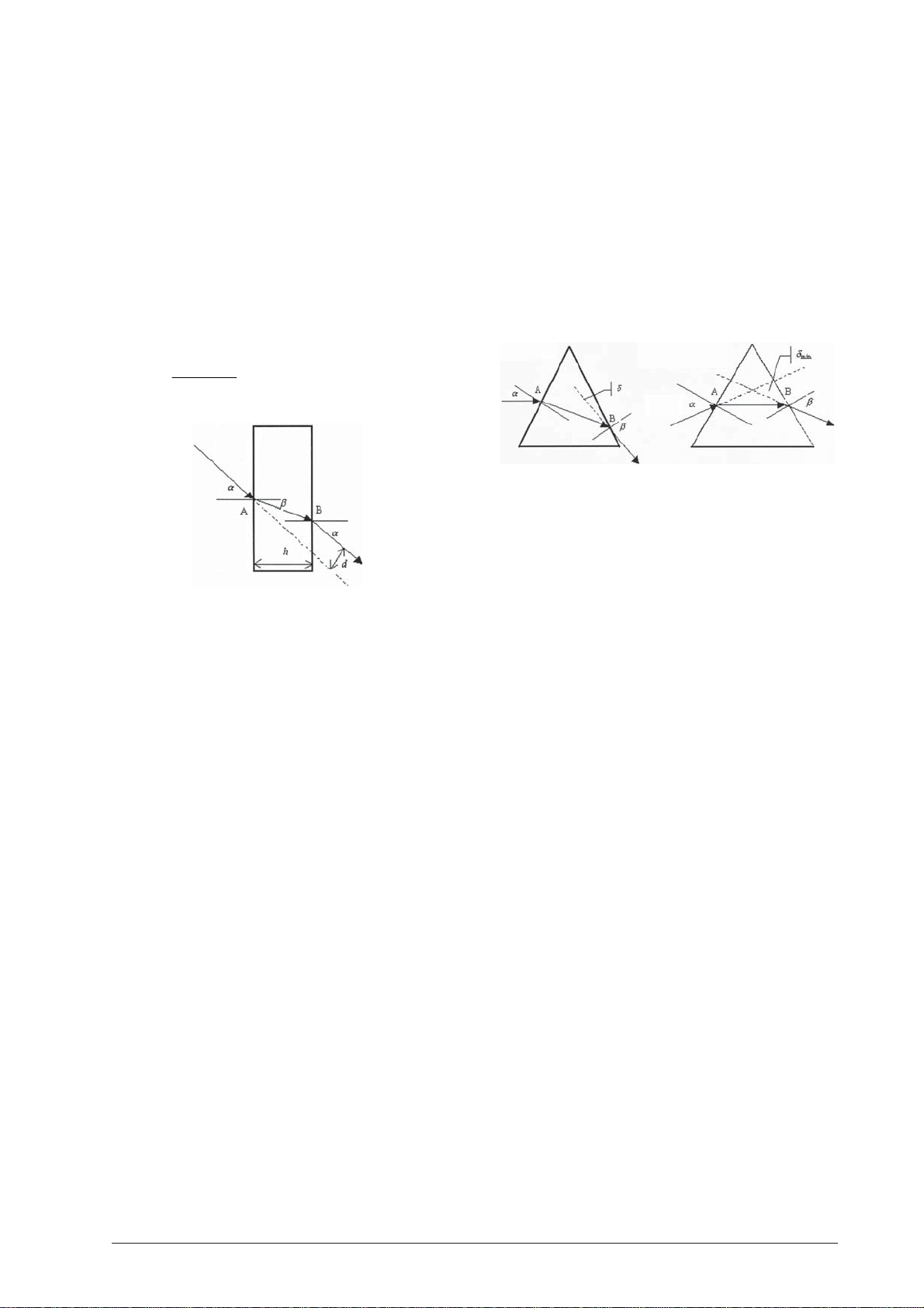
6.3 Durchführung
• Trapezkörper auf der Optischen Scheibe auf der
90°-90°-Linie befestigen, so dass die lange Seite zur
Lichtquelle weist. Der mittlere Teil des Trapezkörpers wirkt wie eine planparalelle Platte.
• Höhe der Scheibe so einstellen, dass der einfallen-
de Lichtstrahl auf der 0°-Linie verläuft und nicht
durch den Trapezkörper gebrochen wird.
• Scheibe drehen, so dass der Strahl gebrochen wird.
• Die Richtung des Strahls wird dabei nicht verän-
dert.
3
Page 4
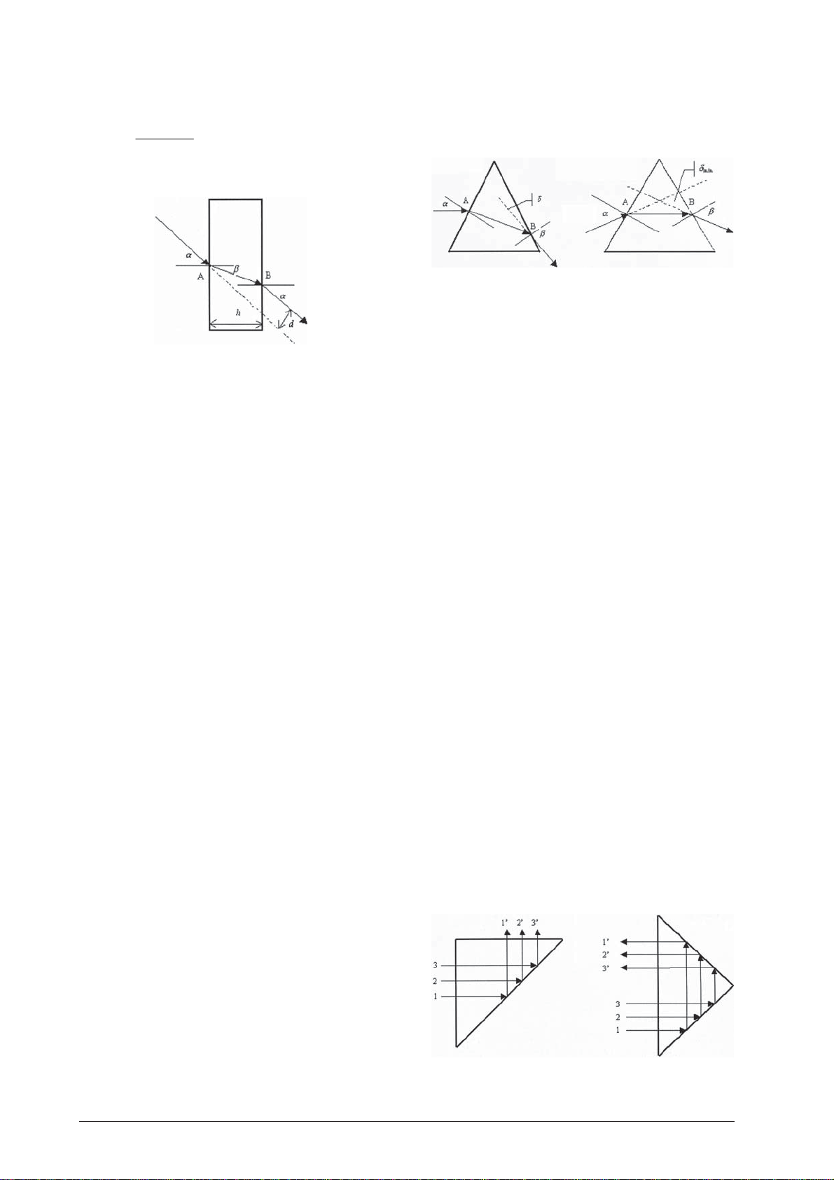
• Der austretende Strahl ist um den Betrag d verscho-
ben. Bei einer Plattendicke h ergibt sich für d:
α−β
sin
()
=
dh
Versuch 7: Brechung an einem Prisma
7.1 Geräte:
• Optische Bank U17150
• Experimentierleuchte U17140
• Objekthalter auf Stiel U17000
• Einfachspalt aus U17040
• Sammellinse f = +150 mm U17108
• Optische Scheibe U17128
• Trapezkörper aus U17128
• Rechtwinkliges Prisma aus U17128
• 3 Reiter 75 mm U17160
• 1 Reiter 30 mm U17161
• Stromversorgung Steckernetzgerät U13900
7.2 Aufbau
• Experimentierleuchte horizontal auf Position 5 cm
platzieren.
• Objekthalter mit Einfachspalt horizontal auf Posi-
tion 20 cm.
• Sammellinse auf Position 25 cm.
• Optische Scheibe mit Trapezkörper auf kleinem
Reiter auf 40 cm.
7.3 Durchführung
• Trapezkörper auf der Optischen Scheibe auf der
90°-90°-Linie befestigen, so dass der spitze Winkel
nach oben weist.
• Höhe der Scheibe so einstellen, dass der einfallen-
de Lichtstrahl auf der 0°-Linie verläuft.
• Nach Drehen der Scheibe fällt der Lichtstrahl auf
den oberen Teil des Trapezkörpers, der dann als
Prisma fungiert.
• In einem Acrylprisma wird ein einfallender Licht-
strahl im Punkt A hin zum Einfallslot gebrochen.
Am Austrittspunkt B findet die Brechung weg vom
Einfallslot statt. Die Summe aller Brechungswinkel
ist der Ablenkungswinkel δ. Es ist der Winkel zwischen dem einfallenden und austretenden Lichtstrahl.
• Es kann gezeigt werden, dass der Einfallswinkel α
bei minimalstem Ablenkungswinkel δ
cos
β
gleich dem
min
Austrittswinkel ß ist. Der gebrochene Strahl verläuft
dann im Prisma parallel zu der Seite, die nicht
durchgangen wird.
Versuch 8: Umkehrprisma
8.1 Geräte:
• Optische Bank U17150
• Experimentierleuchte U17140
• Objekthalter auf Stiel U17000
• Einfach- und Fünffachspalt aus U17040
• Sammellinse f = +150 mm U17108
• Optische Scheibe U17128
• Rechtwinkliges Prisma aus U17128
• 3 Reiter 75 mm U17160
• 1 Reiter 30 mm U17161
• Stromversorgung Steckernetzgerät U13900
8.2 Aufbau
• Experimentierleuchte horizontal auf Position 5 cm
platzieren.
• Objekthalter mit Einfach- bzw. Fünffachspalt hori-
zontal auf Position 20 cm.
• Sammellinse auf Position 25 cm.
• Optische Scheibe mit rechtwinkligem Prisma auf
kleinem Reiter auf 40 cm.
8.3 Durchführung
• Rechtwinkliges Prisma auf der Optischen Scheibe
auf der 90°-90°-Linie befestigen, so dass der rechte
Winkel auf der 0°-Linie liegt und zur Lichtquelle
weist.
• Höhe der Scheibe so einstellen, dass der einfallen-
de Lichtstrahl auf der 0°-Linie verläuft.
• Durch Drehen der Scheibe können alle vorher be-
schriebenen Phänomene beobachtet werden.
• Bei einem bestimmten Winkel (Grenzwinkel) wird
der Strahl total reflektiert.
• Durch Einsatz des Fünffachspalts kann gezeigt wer-
den, dass die Strahlen umgekehrt zurückgeworfen
werden.
4
Page 5
Versuch 9: Konkav und konvex Linsen
9.1 Geräte:
• Optische Bank U17150
• Experimentierleuchte U17140
• Objekthalter auf Stiel U17000
• Fünffachspalt aus U17040
• Sammellinse f = +150 mm U17108
• Optische Scheibe U17128
• Linsen aus U17128
• 3 Reiter 75 mm U17160
• 1 Reiter 30 mm U17161
• Stromversorgung Steckernetzgerät U13900
9.2 Aufbau
• Experimentierleuchte horizontal auf Position 10 cm
platzieren.
• Objekthalter mit Fünffachspalt horizontal auf Po-
sition 22 cm.
• Sammellinse auf Position 27 cm.
• Optische Scheibe mit Linse auf kleinem Reiter.
10.2 Aufbau
• Experimentierleuchte vertikal ganz links platzieren.
• Kondensorlinse f = +50 mm direkt vor die Leuchte
stellen.
• Halter mit Dia auf Position 0. Dia so in den Halter
einsetzen, dass das „F” auf dem Kopf steht.
• Abbildungslinse f = +100 mm auf Position 12 cm.
• Projektionsschirm auf 100 cm.
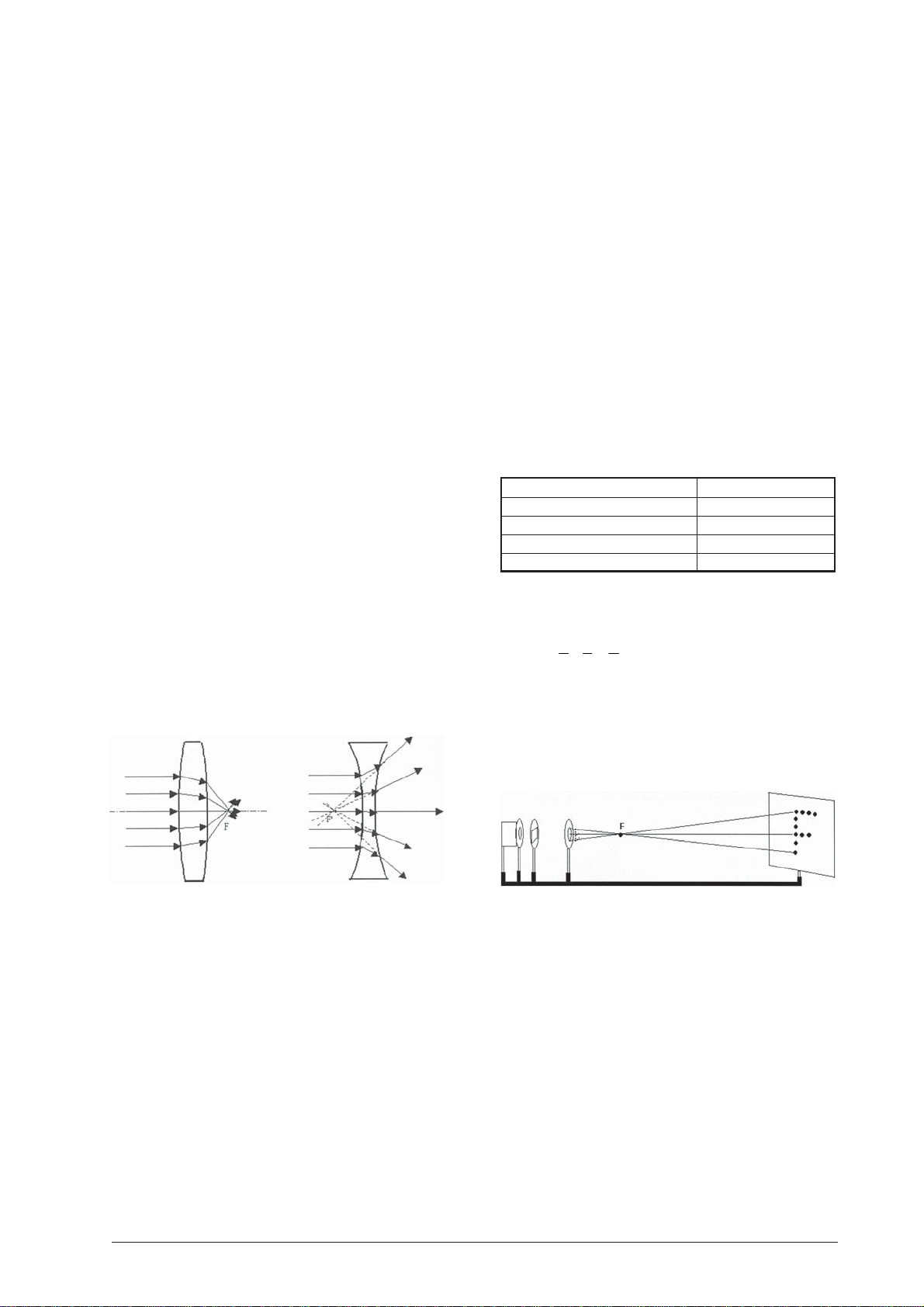
10.3 Durchführung
• Auf dem Projektionsschirm entsteht eine scharfe
Abbildung des Dias.
• Der Abstand zwischen Abbildungslinse und dem
Objekt (Dia) wird als Gegenstandsweite v bezeichnet.
• Der Abstand zwischen Abbildungslinse und Projek-
tionsschirm ist die Bildweite b.
• In diesem Versuch sind v = 12 cm und b = 88 cm
bei einer Brennweite f = +100 mm. Weitere Werte,
bei denen eine scharfe Abbildung entsteht, sind:
9.3 Durchführung
• Konvex Linse zentrisch auf der optischen Scheibe
platzieren.
• Höhe der Scheibe so einstellen, dass der mittlere
einfallende Lichtstrahl auf der 0°-Linie verläuft.
• Eine konvexe Linse ist eine Sammellinse. Die Licht-
strahlen treffen sich nach Durchgang durch die Linse im Brennpunkt F.
• Versuch mit der konkaven Linse wiederholen.
• Die Lichtstrahlen sind divergent nach Durchgang
durch die Linse. Sie bildet kein Objekt ab. Nach
hinten verlängert, treffen sich die Strahlen im virtuellen Brennpunkt F’.
Versuch 10: Linsenformel und Vergrößerung
10.1 Geräte:
• Optische Bank U17150
• Experimentierleuchte U17140
• Objekthalter auf Stiel U17000
• Dia mit Buchstaben „F” aus U17040
• Sammellinse f = +50 mm U17101
• Sammellinse f = +100 mm U17102
• Sammellinse f = +150 mm U17103
• Sammellinse f = +200 mm U17104
• Sammellinse f = +300 mm U17105
• Projektionsschirm U17125
• 4 Reiter 75 mm U17160
• 1 Reiter 30 mm U17161
• Stromversorgung Steckernetzgerät U13900
Gegenstandsweite Bildweite
120 mm 880 mm
130 mm 520 mm
200 mm 200 mm
880 mm 120 mm
• Diese Abstände werden durch die Linsenformel
bestimmt:
11 1
+=
bv f
• Die Vergrößerung kann durch den Quotienten b/v
bestimmt werden.
• Versuch mit weiteren Linsen f = +150 mm,
+200 mm, +300 mm durchführen. Dabei ist zu
beachten, dass der Schirm weiter weg stehen muss.
Versuch 11: Linsenformeln und Vergrößerung,
virtuelle Abbildung
11.1 Geräte:
• Optische Bank U17150
• Experimentierleuchte U17140
• Objekthalter auf Stiel U17000
• Dia mit Buchstaben „F” aus U17040
• Sammellinse f = +50 mm U17101
• Sammellinse f = +100 mm U17102
• Sammellinse f = +150 mm U17103
• Zerstreuungslinse f = –200 mm U17107
• Projektionsschirm U17125
• 4 Reiter 75 mm U17160
• 1 Reiter 30 mm U17161
• Stromversorgung Steckernetzgerät U13900
5
Page 6
11.2 Aufbau
• Experimentierleuchte vertikal ganz links platzieren.
• Kondensorlinse f = +50 mm direkt vor die Leuchte
stellen.
• Halter mit Dia auf Position 0. Dia so in den Halter
einsetzen, dass das „F” auf dem Kopf steht.
• Sammellinsen f = +100 mm und f = +150 mm auf
Position 5 bzw. 25 cm.
• Projektionsschirm auf 55 cm.
11.3 Durchführung
• Auf dem Projektionsschirm entsteht eine doppelt
so große, umgekehrte Abbildung des Dias bei einer Bildweite von 30 cm.
• Nach der Linsenformel beträgt die Gegenstandsweite dann auch 30 cm.
1/b + 1/v = 1/f ; 1/300 + 1/v = 1/150 v = 300 mm
• Daraus folgt, dass die virtuelle, nicht umgekehrte
Abbildung der Linse f = 100 mm bei –5 liegt (d.h.
5 cm links der 0). Dieses Bild hat die gleiche Größe
wie das auf dem Schirm (b = v = 30 cm; b/v = 1).
Die Bildweite ist dann –10 cm (Bild auf –5 , Linse
auf+5). Der Objektabstand beträgt 5 cm. Die Linsenformel bestätigt diese Werte:
1/b + 1/v = 1/f ; –1/100 + 1/50 = 1/100 f = 100 mm
Für die Vergrößerung gilt: b/v = 100/–50 = –2
• Wird nun die Zerstreuungslinse f = –200 mm auf
20, die Sammellinse f = +100 mm und der Schirm
auf 50 platziert, entsteht wieder ein umgekehrtes,
halb so großes Bild wie das Dia. Nach der Linsenformel ist der Objektabstand der Sammellinse
20 cm
1/v = 1/f – 1/b = 1/10 – 1/20 = 1/20
und die Vergrößerung: b/v = 1.
• Für die Zerstreuungslinse ist die Bildweite –10 cm,
gemäß der Linsenformel ist f = –20 cm und die
Vergrößerung b/v = –10/20 = –1/2.
12.2 Aufbau
• Experimentierleuchte vertikal ganz links platzieren.
• Kondensorlinse f = +50 mm direkt vor die Leuchte
stellen.
• Halter mit Dia auf Position 0. Dia so in den Halter
einsetzen, dass das „F” auf dem Kopf steht.
• Abbildungslinse f = +100 mm auf Position 15 cm.
• Projektionsschirm auf 45 cm.
12.3 Durchführung
• Auf dem Projektionsschirm entsteht eine doppelt
so große, umgekehrte Abbildung des Dias. Dieses
Bild wird als virtuelles Bild benutzt, wenn eine andere Linse zwischen Schirm und Linse platziert wird.
• Linse f = +150 mm auf Position 30 und Schirm auf
37,5 platzieren.
• Es entsteht ein umgekehrtes, halb so großes Bild
wie das Dia. Der Vergrößerungsfaktor beträgt jetzt
0,5. Die Gegenstandsweite ist –15 cm, die Bildweite 7,5 cm. Auch hier ist die Linsenformel anwendbar:
1/b + 1/v = 1/f ; 1/75 –1/150 = 1/150 f = 150 mm
• Wird nun die Sammellinse f = +150 mm durch die
Zerstreuungslinse f = –200 mm auf Position 35
ausgetauscht, dann entsteht mit dem Schirm auf
Position 55 eine vier mal so große, umgekehrte
Abbildung bei einer Gegenstandsweite von –10 cm
und einer Bildweite von 20 cm. Die Linsenformel
bestätigt diese Werte:
–1/100 + 1/200 = –1/200 f = –200 mm
Versuch 12: Linsenformel und Vergrößerung,
virtuelles Objekt
12.1 Geräte:
• Optische Bank U17150
• Experimentierleuchte U17140
• Objekthalter auf Stiel U17000
• Dia mit Buchstaben „F” aus U17040
• Sammellinse f = +50 mm U17101
• Sammellinse f = +100 mm U17102
• Sammellinse f = +150 mm U17103
• Zerstreuungslinse f = –200 mm U17107
• Projektionsschirm U17125
• 4 Reiter 75 mm U17160
• 1 Reiter 30 mm U17161
• Stromversorgung Steckernetzgerät U13900
Versuch 13: Linsenfehler, sphärische Abberation 1
13.1 Geräte:
• Optische Bank U17150
• Experimentierleuchte U17140
• Objekthalter auf Stiel U17000
• Fünffachspalt aus U17040
• Sammellinse f = +50 mm U17101
• Sammellinse f = +150 mm U17108
• Irisblende U17010
• Projektionsschirm U17125
• 5 Reiter 75 mm U17160
• 1 Reiter 30 mm U17161
• Stromversorgung Steckernetzgerät U13900
13.2 Aufbau
• Experimentierleuchte vertikal auf Position 0 plat-
zieren.
• Linse f = +150 mm auf Position 21 cm stellen.
• Halter mit horizontalem Fünffachspalt auf 26 cm.
• Projektionsschirm auf 50 cm.
6
Page 7
13.3 Durchführung
• Bei dünnen Linsen werden parallele Lichtstrahlen
am Randbereich und im Mittelteil der Linse unterschiedlich gebrochen, so dass zwei Brennpunkte
entstehen. Dieses Phänomen wird sphärische Abberation genannt.
• Mittels des Fünfachspalts und der Linse werden 5
parallele Lichtstrahlen erzeugt.
• Schirm so entlang der Bank ausrichten, dass die
Strahlen längs des Schirms verlaufen. Gegebenenfalls auch die Leuchte drehen.
• Linse f = +50 mm direkt vor den Schirm platzieren
(auf ca. 36 cm). Der Brennpunkt, die konvergierenden sowie die divergierenden Strahlen sind jetzt
deutlich sichtbar. Brennpunkt auf dem Schirm
markieren.
• Mittels der Irisblende (auf Position ca. 31 cm) kön-
nen nun die Randstrahlen ausgeblendet werden.
Es ist eine Verschiebung des Brennpunkts beobachtbar. Zudem ist der Brennpunkt deutlich
schärfer abgebildet.
Versuch 15: Linsenfehler, chromatische Abberation
15.1 Geräte:
• Optische Bank U17150
• Experimentierleuchte U17140
• Objekthalter auf Stiel U17000
• Lochblende aus U17040
• Sammellinse f = +150 mm U17103
• Projektionsschirm U17125
• 3 Reiter 75 mm U17160
• 1 Reiter 30 mm U17161
• Stromversorgung Steckernetzgerät U13900
15.2 Aufbau
• Experimentierleuchte vertikal auf Position 0 plat-
zieren.
• Linse f = +150 mm auf Position 23 cm stellen.
• Projektionsschirm auf 95 cm.
Versuch 14: Linsenfehler, sphärische Abberation 2
14.1 Geräte:
• Optische Bank U17150
• Experimentierleuchte U17140
• Objekthalter auf Stiel U17000
• Lochblende aus U17040
• Sammellinse f = +50 mm U17101
• Projektionsschirm U17125
• 3 Reiter 75 mm U17160
• 1 Reiter 30 mm U17161
• Stromversorgung Steckernetzgerät U13900
14.2 Aufbau
• Experimentierleuchte vertikal auf Position 0 plat-
zieren.
• Linse f = +50 mm auf Position 11 cm stellen.
• Halter mit Lochblende auf 6 cm.
• Projektionsschirm auf 50 cm.
14.3 Durchführung
• Mittels der Linse den Glühdraht der Lampe so scharf
wie möglich auf dem Schirm abbilden.
• Lochblende auf der optischen Bank platzieren.
Durch Ausgrenzung der äußeren Lichtstrahlen entsteht ein noch schärferes Bild.
• Die Veränderung der Schärfe der Abbildung wird
durch die Verschiebung des Brennpunkts verursacht.
15.3 Durchführung
• Mittels der Linse den Glühdraht der Lampe so scharf
wie möglich auf dem Schirm abbilden.
• Durch Verschieben des Schirms nach rechts verfärbt
sich der Rand der Abbildung bläulich. Wird der
Schirm nach links verschoben, dann geht die Farbe des Rands in den roten Bereich.
• Diese Farbveränderung wird dadurch verursacht,
dass die Lichtstrahlen im Zentrum der Linse und
die am Rand unterschiedlich gebrochen werden.
Dieses Phänomen wird Farbverschiebung oder
chromatische Abberation genannt.
• Wird nun die Lochblende hinter die Linse gestellt
(auf Position 28 cm) entsteht ein sehr scharfes Bild
des Glühdrahts der Lampe ohne Farbverschiebung.
• In der Praxis wird die chromatische Abberation von
Linsen durch eine Kombination von Sammel- und
Zerstreuungslinsen weitgehend beseitigt.
• Linsen ohne sphärische Abberation sind asphäri-
sche Linsen, solche ohne chromatische Abberation
heißen achromatische Linsen.
7
Page 8
Versuch 16: Modell einer Camera obscura
16.1 Geräte:
• Optische Bank U17150
• Experimentierleuchte U17140
• Objekthalter auf Stiel U17000
• Dia mit Buchstaben „F” aus U17040
• Sammellinse f = +150 mm U17103
• Projektionsschirm U17125
• 3 Reiter 75 mm U17160
• 1 Reiter 30 mm U17161
• Stromversorgung Steckernetzgerät U13900
16.2 Aufbau
• Experimentierleuchte vertikal auf Position 0 platzieren.
• Halter mit Dia auf Position 14 cm.
• Linse f = +150 mm auf Position 32 cm stellen.
• Projektionsschirm auf 84 cm.
16.3 Durchführung
• Der Buchstabe „F” wird scharf und umgekehrt auf
dem Schirm abgebildet.
• Linsenfehler können durch das Platzieren der Iris-
blende auf Position 38 cm beseitigt werden.
Versuch 18: Modell eines Mikroskops
18.1 Geräte:
• Optische Bank U17150
• Experimentierleuchte U17140
• Objekthalter auf Stiel U17000
• Sammellinse f = +50 mm U17101
• Sammellinse f = +100 mm U17102
• Sammellinse f = +150 mm U17103
• Irisblende U17010
• Projektionsschirm U17125
• 5 Reiter 75 mm U17160
• 1 Reiter 30 mm U17161
• Stromversorgung Steckernetzgerät U13900
Versuch 17: Modell eines Dia-Projektors
17.1 Geräte:
• Optische Bank U17150
• Experimentierleuchte U17140
• Objekthalter auf Stiel U17000
• Dia
• Sammellinse f = +50 mm U17101
• Sammellinse f = +100 mm U17102
• Irisblende U17010
• Projektionsschirm U17125
• 5 Reiter 75 mm U17160
• 1 Reiter 30 mm U17161
• Stromversorgung Steckernetzgerät U13900
17.2 Aufbau
• Experimentierleuchte vertikal auf Position 0 platzieren.
• Kondensorlinse f = +50 mm auf Position 10 cm
stellen.
• Objekthalter auf Position 15 cm. Das Dia muss auf
dem Kopf stehend im Halter sein.
• Linse f = +100 mm auf 27 cm.
• Projektionsschirm auf 100 cm.
18.2 Aufbau
• Experimentierleuchte vertikal auf Position 0 plat-
zieren.
• Objekthalter auf Position 25 cm. Als Objekt dient
eine Münze, die mit Klebeband in der Mitte des
Halters befestigt ist.
• Linse f = +50 mm auf Position 30 cm stellen.
• Linse f = +100 mm auf 54 cm.
• Projektionsschirm auf 100 cm.
18.3 Durchführung
• Die Linse f = +50 mm dient als Objektiv.
• Die Linse f = +100 mm bildet das Objekt scharf
auf dem Schirm ab.
• Beleuchtung ausschalten und Schirm entfernen.
• Die Linse f = +150 mm auf Position 74 cm platzieren.
Sie bildet zusammen mit der Linse f = +100 mm das
Okular.
• Das virtuelle Bild der Münze wird wahrgenommen,
als wenn man durch die Linse f = +150 mm blicken würde.
• Die Irisblende auf 35 cm platziert ergibt ein besse-
res Bild.
• Auch transparente Objekte (Präparate) sind einsetz-
bar. Der Vergrößerungsfaktor in diesem Modell ist
nicht sehr groß. In der Praxis sind die Brennpunktabstände viel kleiner.
17.3 Durchführung
• Die Linse f = +100 mm dient als Objektiv. Das Dia
wird scharf auf dem Schirm abgebildet. Die Schärfe des Bilds kann durch Verschieben der Lichtquelle korrigiert werden.
8
Page 9
Versuch 19: Modell eines astronomischen Fernrohrs
19.1 Geräte:
• Optische Bank U17150
• Sammellinse f = +100 mm U17102
• Sammellinse f = +300 mm U17105
• 2 Reiter 75 mm U17160
19.2 Aufbau
• Linse f = +100 mm auf Position 0 platzieren.
• Linse f = +300 mm verschiebbar
19.3 Durchführung
• Durch die Linse f = +100 mm ein entferntes Ob-
jekt (wenigstens 10 m) anvisieren.
• Die Linse f = +300 mm auf der Bank verschieben
bis das Objekt scharf zu sehen ist. Das Bild ist umgekehrt und lichtstark.
Versuch 20: Modell einer Fotokamera
20.1 Geräte:
• Optische Bank U17150
• Sammellinse f = +100 mm U17102
• Irisblende U17010
• Projektionsschirm U17125
• 2 Reiter 75 mm U17160
• 1 Reiter 30 mm U17161
20.2 Aufbau
• Linse f = +100 mm auf Position 30 cm platzieren.
• Projektionsschirm verschiebbar
20.3 Durchführung
• Die optische Bank auf ein Objekt ausrichten und
durch Verschieben des Schirms in Richtung Linse
eine scharfe Abbildung herstellen. Das Bild steht
auf dem Kopf.
• Durch Platzieren der Irisblende hinter die Linse wird
das Bild schärfer aber auch lichtschwächer. Die Tiefenschärfe ist hier nicht kritisch.
Versuch 21: Modell eines holländischen Fernrohrs
21.1 Geräte:
• Optische Bank U17150
• Zerstreuungslinse f = –100 mm U17106
• Sammellinse f = +300 mm U17105
• 2 Reiter 75 mm U17160
21.2 Aufbau
• Linse f = +300 mm auf Position 30 cm platzieren.
• Linse f = –100 mm verschiebbar
21.3 Durchführung
• Durch die Linse f = –100 mm ein entferntes Objekt
(wenigstens 10 m) anvisieren.
• Die Linse f = +300 mm auf der Bank verschieben
bis das Objekt scharf zu sehen ist. Das Bild ist aufrecht stehend und lichtstark.
Versuch 22: Polarisation, Modell eines Polarimeters
22.1 Geräte:
• Optische Bank U17150
• Experimentierleuchte U17140
• Objekthalter auf Stiel U17000
• Drehbarer Objekthalter U17001
• Prismentisch U17020
• Sammellinse f = +50 mm U17101
• Sammellinse f = +100 mm U17102
• Rundküvette U14313
• Polarisationsfilter U40129
• Projektionsschirm U17125
• 6 Reiter 75 mm U17160
• 1 Reiter 30 mm U17161
• Stromversorgung Steckernetzgerät U13900
22.2 Aufbau
• Experimentierleuchte vertikal auf Position 0 plat-
zieren.
• Linse f = +50 mm auf Position 8,5 cm stellen.
• Objekthalter auf Position 13,5 cm.
• Prismentisch auf Position 20 cm.
• Drehbarer Objekthalter auf 28 cm
• Projektionsschirm auf 100 cm.
22.3 Durchführung
• Auf dem Schirm ist der Glühdraht der Lampe zu
sehen.
• Die beiden Polarisationsfilter aufeinanderlegen und
dann drehen bis sie das meiste Licht durchlassen.
In dieser Position in den Objekthaltern platzieren.
• Der Objekthalter dient als Polarisator, der drehba-
re Halter als Analysator.
• Den drehbaren Halter so lange drehen, bis der Glüh-
draht der Lampe nicht mehr auf dem Schirm zu
sehen ist. Die Filter stehen dann über Kreuz.
• Rundküvette mit einer Zuckerlösung auf dem Pris-
mentisch und die Linse f = +100 mm auf Position
37,5 cm platzieren.
• Durch die Zuckerlösung tritt eine Drehung der Po-
larisationsebene ein, so dass jetzt wieder Licht auf
dem Schirm zu sehen ist.
9
Page 10

• Abhängig von der Konzentration der Zuckerlösung
muss der Analysator mehr oder weniger gedreht
werden, um Auslöschung zu erreichen.
Versuch 23: Geradsichtprisma, Absorptionsspektrum
23.1 Geräte:
• Optische Bank U17150
• Experimentierleuchte U17140
• Prismentisch U17020
• Verstellbarer Spalt U17015
• Halter für Geradsichtprisma U17025
• Geradsichtprisma U14020
• Sammellinse f = +50 mm U17101
• Sammellinse f = +100 mm U17102
• Küvette, rechteckig U17129
• Satz Farbfilter U21878
• Projektionsschirm U17125
• 5 Reiter 75 mm U17160
• 1 Reiter 30 mm U17161
• Kaliumpermanganat (KmnO
)
4
• Stromversorgung Steckernetzgerät U13900
23.2 Aufbau
• Experimentierleuchte vertikal auf Position 0 platzieren.
• Linse f = +50 mm auf Position 8,5 cm stellen.
• Verstellbaren Spalt auf 14 cm.
• Linse f = +100 mm auf Position 8,5 cm.
• Projektionsschirm auf 100 cm.
23.3 Durchführung
• Durch Verschieben der Linse f = +100 mm eine
scharfe Abbildung des Spalts auf dem Schirm erzeugen. Die Abbildung sollte ca. 3 mm breit sein.
• Geradsichtprisma so im Halter auf Position 26,5 cm
positionieren, dass die geschliffenen Flächen senkrecht stehen und der Lichtstrahl durch deren Mitte
geht. Gegebenenfalls mittels der Lichtquelle und
der Abbildungslinse korrigieren.
• Durch Regelung des verstellbaren Spalts kann das
Spektrum intensiver und schärfer eingestellt werden.
• Diese Aufstellung ist die Ausgangsstellung für alle
Versuche mit dem Geradsichtprisma.
• Da die Halogenlampe ein fester Körper ist, handelt
es sich bei dem Spektrum um ein kontinuierliches
Spektrum.
• Wird nun vor das Prisma ein Farbfilter (z.B. rot) plat-
ziert, entsteht im Spektrum an der roten Stelle ein
schwarzes Band. Dieses Spektrum ist ein Absorptionsspektrum.
• Statt der Farbfilter kann auch die Küvette, gefüllt
z.B. mit einer Lösung von Kaliumpermanganat in
Wasser, auf dem Prismentisch vor das Prisma gestellt werden. Es entstehen dann mehrere schwarze Bänder im Spektrum.
Versuch 24: Linienspektrum
24.1 Geräte:
• Optische Bank U17150
• Drossel für Spektrallampen U21905
• Spektrallampen z.B. U13033 HG
• Verstellbarer Spalt U17015
• Halter für Geradsichtprisma U17025
• Geradsichtprisma U14020
• Sammellinse f = +50 mm U17101
• Sammellinse f = +100 mm U17102
• Projektionsschirm U17125
• 5 Reiter 75 mm U17160
• 1 Reiter 30 mm U17161
• Stromversorgung Steckernetzgerät U13900
24.2 Aufbau 1
• Halter mit Spektrallampe auf Position 0 platzieren.
• Linse f = +50 mm auf Position 5 cm stellen.
• Verstellbaren Spalt auf 10 cm.
• Linse f = +100 mm auf Position 21,5 cm.
• Projektionsschirm auf 100 cm.
24.3 Durchführung
• Nach Einschalten der Spektrallampe ungefähr 5
Minuten warten bis die Lampe mit maximaler Lichtstärke leuchtet.
• Durch Verschieben der Linse f = +100 mm eine
scharfe Abbildung des Spalts auf dem Schirm erzeugen.
• Geradsichtprisma so im Halter auf Position 26,5 cm
positionieren, dass die geschliffenen Flächen senkrecht stehen und der Lichtstrahl durch deren Mitte
geht. Gegebenenfalls mittels der Lichtquelle und
der Abbildungslinse korrigieren.
• Es entsteht ein Linienspektrum von Quecksilber.
• Durch Regelung des verstellbaren Spalts kann das
Spektrum intensiver und schärfer eingestellt werden.
10
Page 11
24.4 Aufbau 2
• Um sehr intensive Linien zu bekommen kann fol-
gender Aufbau vorgenommen werden. Die Spektrallinien haben dann die gleiche Größe wie der
Spalt.
• Halter mit Spektrallampe auf Position 0 platzieren.
• Linse f = +50 mm auf Position 5 cm stellen.
• Verstellbaren Spalt auf 10 cm.
• Linse f = +100 mm auf Position 21,5 cm.
• Geradsichtprisma auf Position 26,5 cm.
Projektionsschirm auf 50 cm.
3B Scientific GmbH • Rudorffweg 8 • 21031 Hamburg • Deutschland • www.3bscientific.com • Technische Änderungen vorbehalten
11
Page 12

3B SCIENTIFIC3B SCIENTIFIC
3B SCIENTIFIC®
3B SCIENTIFIC3B SCIENTIFIC
PHYSICSPHYSICS
PHYSICS
PHYSICSPHYSICS
Basic Experiments in Optics on the Optical Bench U17150
Instruction Sheet
1/05 MH
®
Overview of the Experiments:
Experiment 1: Demonstration of the various ray
beams
Experiment 2: Reflection of a ray of light from a plane
mirror
Experiment 3: Reflection of a light beam from a plane
mirror
Experiment 4: Reflection of a light beam from a con-
cave or convex mirror
Experiment 5: Snell's law of refraction
Experiment 6: Refraction of light through a plane-
parallel plate
Experiment 7: Refraction of light through a prism
Experiment 8: Inverting prisms
Experiment 9: Concave and convex lenses
Experiment 10: Lens formula and magnification
Experiment 11: Lens formulas and magnification, vir-
tual image
Experiment 12: Lens formula and magnification, vir-
tual object
Experiment 13: Lens error, spherical aberration 1
Experiment 14: Lens error, spherical aberration 2
Experiment 15: Lens error, chromatic aberration
Experiment 16: Model of a camera obscura
Experiment 17: Model of a slide projector
Experiment 18: Model of a microscope
Experiment 19: Model of an astronomy telescope
Experiment 20: Model of a camera
Experiment 21: Model of a Galileo telescope
Experiment 22: Polarization, model of a polorimeter
Experiment 23: Direct-vision (Amici) prism, absorption
spectrum
Experiment 24: Line spectrum
2. Experiment examples
Experiment 1: Demonstration of various ray
beams
1.1 Equipment:
• Optical bench U17150
• Experimental lamp U17140
• Object holder, shaft-mounted U17000
• Fivefold slit from U17040
• Convex lens f = +150 mm U17108
• Projection screen U17125
• 3 optical riders 75 mm U17160
• 1 optical rider 30 mm U17161
• Plug-in power supply unit U13900
1.2 Set up
• Place the experimental lamp horizontally on the
rail at the 10 cm position.
• Place the object holder with five-fold slit horizon-
tally on the rail at the 20 cm position
• Place the convex lens at the 25 cm position.
• Mount the projection screen on the small rider.
1.3 Procedure
• When the convex lens is not used, the ray beam is
divergent.
• When the convex lens is placed at the 25 cm posi-
tion we obtain a parallel beam of rays.
• When the convex lens is moved away from the light
source a converging beam of rays is produced.
1. Safety instructions
• Warning! Lamps become extremely hot when op-
erated for prolonged periods of time.
• Do not clean any of the optical components with
aggressive fluids or solvents. This could cause damage!
Experiment 2: Reflection of a ray of light from a
plane mirror
2.1 Equipment:
• Optical bench U17150
• Experimental lamp U17140
12
Page 13
• Object holder, shaft mounted U17000
• Diaphragm with single slit from U17040
• Convex lens f = +150 mm U17108
• Optical disc U17128
• Plane mirror from U17128
• 3 optical riders 75 mm U17160
• 1 optical rider 30 mm U17161
• Plug-in power supply U13900
2.2 Set up
• Place the experimental lamp horizontally on the
rail at the 10 cm position.
• Place the object holder with single-slit diaphragm
horizontally on the rail at the 20 cm position.
• Place the concave lens at the 25 cm position.
• Mount the optical disc with plane mirror on a small
optical rider at the 40 cm position.
2.3 Procedure
• Fasten the plane mirror mounted on the optical
disc to the 90° to -90° line.
• Set the height of the disc so that the incident light
ray is reflected from the 0° line.
• By rotating the disc we can verify the law of reflec-
tion, which states that the angle of incidence is
equal to the angle of reflection.
• Attach the optical disc with plane mirror to the
small rider positioned at 40 cm.
3.3 Procedure
• Attach the plane mirror on the optical disc at the
90°-90° line.
• Adjust the height of the disc so that the middle ray
of light propagates along the 0° line and all rays
are reflected into each other.
• By rotating the disc it is demonstrated that a paral-
lel incident beam of light is also parallel after being reflected.
• By moving the lens away from the light source it
can be demonstrated that a converging light beam
is also reflected as a converging light beam.
• Without the use of the convex lens it can be dem-
onstrated that a divergent light beam also diverges
upon reflection.
Experiment 3: Reflection of a light beam from a
plane mirror
3.1 Equipment:
• Optical bench U17150
• Experimental lamp U17140
• Object holder, shaft-mounted U17000
• Fivefold slit from U17040
• Convex lens f = +150 mm U17108
• Optical disc U17128
• Plane mirror from U17128
• 3 optical riders 75 mm U17160
• 1 optical rider 30 mm U17161
• Plug-in power supply unit U13900
3.2 Set up
• Place the experimental lamp horizontally on the
rail at the 10 cm position.
• Place the object holder with the five-fold slit at the
20 cm position.
• Place the convex lens at the 25 cm position.
Experiment 4: Reflection of a light beam from a
concave or convex mirror
4.1 Equipment:
• Optical bench U17150
• Experimental lamp U17140
• Object holder, shaft-mounted U17000
• Fivefold slit from U17040
• Concave lens f = +150 mm U17108
• Optical disc U17128
• Mirror from U17128
• 3 optical riders 75 mm U17160
• 1 optical rider 30 mm U17161
• Plug-in power supply U13900
4.2 Set up
• Place the experimental lamp horizontally on the
rail at the 10 cm position.
• Place the object holder with five-fold slit horizon-
tally on the rail at the 20 cm position.
• Place the convex lens at the 25 cm position.
• Place the optical disc with convex mirror on the
small rider at the 40 cm position.
4.3 Procedure
• Fasten the concave mirror on the optical disc on
the 90°-90° line.
• Adjust the height of the disc so that the middle ray
of light travels along the 0° line and is reflected
into itself.
13
Page 14
• Use the lens to generate a parallel beam.
• The incidenting rays are reflected so that they all
pass through and converge at a single point F. This
point is the focal point of the mirror.
• Repeat the experiment with converging and diverg-
ing light beams.
• Result: a concave mirror causes the rays to converge.
• Rotate the optical disc by 180° so that the incident
rays are reflected by the convex mirror. Carry out
the same procedural steps as stated above.
• A convex mirror causes the rays to diverge.
Experiment 5: Snell's law of refraction
5.1 Equipment:
• Optical bench U17150
• Experimental lamp U17140
• Object holder, shaft-mounted U17000
• Diaphragm with single slit from U17040
• Concave lens f = +150 mm U17108
• Optical disc U17128
• Semi-circular body from U17128
• 3 optical riders 75 mm U17160
• 1 optical rider 30 mm U17161
• Plug-in power supply unit U13900
refracted away from the normal at the point of incidence.
• When the light ray passes from one medium with
the refractive index n1 to another medium with the
refractive index n2 its directional change is determined by Snell's law of refraction:
sin α / sin ß = constant or sin α / sin ß = n
α is the angle of incidence in medium n
/ n
2
and ß is
1
the angle of refraction in medium n2.
• The bigger the angle of incidence is, the larger the
angle of refraction becomes. If n1 < n2, there is a
critical angle α. At this angle the refracted ray of
light is refracted along the interface between two
media. If the angle of incidence is greater than the
critical angle, then there is no longer any refraction and all light is reflected. This case is referred
to as total internal reflection.
1
5.2 Set up
• Place the experimental lamp horizontally on the
rail at the 10 cm position.
• Place the object holder with single slot diaphragm
horizontally on the rail at the 20 cm position.
• Place the concave lens at the 25 cm position.
• Mount the optical disc with semi-circular body on
the small rider at the 40 cm position.
5.3 Procedure
• Fasten the semi-circular body on the optical disc
on the 90°-90° line so that the plane side is facing
the light source.
• Adjust the height of the disc so that the incident-
ing light ray propagates along the 0° line and is
incident at the precise center of the semicircular
body. The ray of light then propagates uninterrupted along the 0° line.
• When the disc is rotated, the light ray is refracted
toward the normal at the point of incidence.
• The disc is now rotated by 180° so that the convex
disc is facing the light source. The light ray is now
Experiment 6: Refraction in a plane-parallel plate
6.1 Equipment:
• Optical bench U17150
• Experimental lamp U17140
• Object holder shaft-mounted U17000
• Diaphragm with single slit from U17040
• Concave lens f = +150 mm U17108
• Optical disc U17128
• Trapezoidal body from U17128
• 3 Optical rider 75 mm U17160
• 1 Optical rider 30 mm U17161
• Plug-in power supply unit U13900
6.2 Set up
• Place the experimental lamp horizontally on the
rail at the 5 cm position.
• Set up the object holder including diaphragm with
single slit at the 20 cm position.
• Place the concave lens at the 25 cm position.
• Set up the optical disc with trapezoidal body on
the small optical rider at the 40 cm position.
14
Page 15
6.3 Procedure
• Fasten the trapezoidal body on the optical disc
along the 90° to -90° line so that its long side faces
the light source. The middle section of the trapezoidal body acts like a plane-parallel plate.
• Adjust the height of the disc so that the incident-
ing light beam propagates on the 0° line and is not
refracted by the trapezoidal body.
• Rotate the disc so that the beam is now refracted.
• The direction of the outgoing light ray is not al-
tered.
• The outgoing light ray is nevertheless diverted from
its original path by a distance d. For a plate of h
density, this gives the following for d:
α−β
sin
()
=
dh
Experiment 7: Refraction at a prism
7.1 Equipment:
• Optical bench U17150
• Experimental lamp U17140
• Object holder shaft-mounted U17000
• Diaphragm with single slit from U17040
• Concave lens f = +150 mm U17108
• Optical disc U17128
• Trapezoidal body from U17128
• Right-angled prism from U17128
• 3 Optical rider 75 mm U17160
• 1 Optical rider 30 mm U17161
• Plug-in power supply unit U13900
7.2 Set up
• Place the experimental lamp at the 5 cm position.
• Set up the object holder with diaphragm including
single slit at the 20 cm position.
• Place the concave lens at the 25 cm position.
• Set the optical disc with trapezoidal body on the
small optical rider at the 40 cm position.
7.3 Procedure
• Fasten the trapezoidal body onto the optical disc
along the 90° to -90° line so that the pyramid points
upwards.
• Adjust the height of the disc so that the incident
light ray travels on the 0° line.
• After the disc is rotated, the light ray incidents on
the upper section of the trapezoidal body, which
now functions, like a prism.
cos
β
• In an acrylic prism the light ray incident at point A
is refracted from the axis of incidence. At the emerging point B the ray is refracted away from the axis
of incidence. The sum total of all refraction angles
is called the deflection angle δ. This is the angle
between the incident and emerging light rays.
• It can be demonstrated that the incident angle α
at the minimum deflection angle δ
the emerging angle ß. The refracted ray then propagates inside the prism parallel to the side, which
is not passed through.
Experiment 8: Inverting prisms
8.1 Equipment:
• Optical bench U17150
• Experimental lamp U17140
• Object holder shaft-mounted U17000
• Diaphragm with single and fivefold slit from U17040
• Concave lens f = +150 mm U17108
• Optical disc U17128
• Right-angled prism from U17128
• 3 Optical rider 75 mm U17160
• 1 Optical rider 30 mm U17161
• Plug-in power supply unit U13900
8.2 Set up
• Place the experimental lamp horizontally on the
rail at the 5 cm position.
• Place the object holder including a diaphragm with
single or five-fold slot horizontally on rail at the
20 cm position.
• Set up the concave lens at the 25 cm position.
• Set the optical disc with right-angled prism on the
small optical rider at the 40 cm position.
8.3 Procedure
• Fasten the right-angled prism on the optical disc
along the 90°-90° line so that the right angle is lined
up with the 0° line and faces the light source.
• Adjust the height of the disc so that the incident
light beam propagates on the 0° line.
• By rotating the disc all of the previously described
phenomena can be observed.
• At a certain angle (limiting angle) the ray is subject
to total internal reflection.
• Using the diaphragm with fivefold slit, it can be
demonstrated that the rays can be reflected back
in the direction from which they came.
is equal to
min
15
Page 16
Experiment 9: Concave and convex lenses
9.1 Equipment:
• Optical bench U17150
• Experimental lamp U17140
• Object holder shaft-mounted U17000
• Diaphragm with fivefold slit from U17040
• Concave lens f = +150 mm U17108
• Optical disc U17128
• Lenses from U17128
• 3 Optical rider 75 mm U17160
• 1 Optical rider 30 mm U17161
• Plug-in power supply unit U13900
• Object holder, shaft-mounted U17000
• Slide with letter “F” from U17040
• Concave lens f = +50 mm U17101
• Concave lens f = +100 mm U17102
• Concave lens f = +150 mm U17103
• Concave lens f = +200 mm U17104
• Concave lens f = +300 mm U17105
• Projection screen U17125
• 4 optical rider 75 mm U17160
• 1 optical rider 30 mm U17161
• Plug-in power supply unit U13900
10.2 Set up
• Place the experimental lamp vertically on the rail
at the left-hand end.
• Situate the condensing lens f = +50 mm directly in
front of the lamp.
• Insert the slide into the holder at the 0 position.
The slot is inserted in the holder so that the letter
“F” is upside down.
• Place the imaging lens f = +100 at the 12 cm posi-
tion.
• Set up the projection screen at 100 cm.
9.2 Set up
• Place the experimental lamp horizontally on the
rail at the 10 cm position.
• Set the object holder up with fivefold slit horizon-
tally on the rail at the 22 cm position.
• Place the concave lens at the 27 cm position.
• Set up the optical disc with lens on the small opti-
cal rider.
9.3 Procedure
• Place the convex lens in a central position on the
optical disc.
• Adjust the height of the disc so that the center of
the incident light beam propagates on the 0° line.
• A convex lens is a converging lens. After passing
through the medium the light rays all converge at
the focal point F.
• Repeat the experiment using the concave lens.
• The light rays diverge after passing through the lens.
No image of an object emerges. Tracing the divergent rays backwards one arrives at a virtual focal
point F' where these lines meet.
10.3 Procedure
• A sharp image of the slide appears on the projec-
tion screen.
• The distance between the imaging lens and the
object (slide) is referred to as the object distance v.
• The distance between the imaging lens and the
projection screen is called the image distance b.
• In this experiment we have v = 12 cm and b = 88 cm
at a focal length f = +100 mm. Additional values
which result in the production of a sharp image
are:
Object distance Image distance
120 mm 880 mm
130 mm 520 mm
200 mm 200 mm
880 mm 120 mm
• These distances are determined by the lens formu-
la:
11 1
+=
bv f
• The magnification can be determined by the ratio
b/v.
• Perform the experiment with additional lenses
f = +150 mm, +200 mm, +300 mm. At the same
time be sure to move the screen further and further away.
Experiment 10: Lens formula and magnification
10.1 Equipment:
• Optical bench U17150
• Experimental lamp U17140
16
Page 17
Experiment 11: Lens formula and magnification,
virtual images
11.1 Equipment:
• Optical bench U17150
• Experimental lamp U17140
• Object holder, shaft-mounted U17000
• Slide with letter “F” from U17040
• Concave lens f = +50 mm U17101
• Concave lens f = +100 mm U17102
• Concave lens f = +150 mm U17103
• Diverging lens f = –200 mm U17107
• Projection screen U17125
• 4 optical riders 75 mm U17160
• 1 optical rider 30 mm U17161
• Plug-in power supply unit U13900
Experiment 12: Lens formula and magnification,
virtual object
12.1 Equipment:
• Optical bench U17150
• Experimental lamp U17140
• Object holder, shaft-mounted U17000
• Slide with letter “F” from U17040
• Concave lens f = +50 mm U17101
• Concave lens f = +100 mm U17102
• Concave lens f = +150 mm U17103
• Diverging lens f = –200 mm U17107
• Projection screen U17125
• 4 Optical rider 75 mm U17160
• 1 Optical rider 30 mm U17161
• Plug-in power supply unit U13900
11.2 Set up
• Place the experimental lamp vertically on the rail
at the left end position.
• Set up the converging lens f = +50 mm directly in
front of the lamp.
• Place the holder with slide at the 0 position, insert-
ing the slide into the holder so that the “F” is upside down.
• Place the concave lenses f = +100 mm and
f = +150 mm at the 5 or 25 cm positions.
• Set the projection screen up at the 55 cm position.
11.3 Procedure
• An inverse image of the slide twice the size of the
original is produced at a focal length of 30 cm.
• According to the lens equation the object distance
then also amounts to 30 cm.
1/b + 1/v = 1/f ; 1/300 + 1/v = 1/150 v = 300 mm
• We conclude from this that the virtual, non-invert-
ed image of the lens f = 100 mm lies at –5 (i.e 5 cm
left of 0). This image is the same size as the one on
the screen (b = v = 30 cm; b/v = 1). The focal length
is therefore –10 cm (image at –5 , lens at +5). The
object distance amounts to 5 cm. The lens equation verifies these values:
1/b + 1/v = 1/f ; –1/100 + 1/50 = 1/100 f = 100 mm
The following holds true for the magnification:
b/v = 100/–50 = –2
• If the diverging lens f = –200 mm is now placed at
the 20 cm position, the concave lens f = +100 mm
and the screen placed at 50, an inverted image is
produced, which is half as large as that on the slide.
According to the lens equation the object distance
to the concave lens is 20 cm
1/v = 1/f – 1/b = 1/10 – 1/20 = 1/20
and the magnification is: b/v = 1.
• For the diverging lens the image distance is –10 cm,
according to the lens formula, we obtain f = –20 cm
and a magnification b/v = –10/20 = –1/2.
12.2 Set up
• Place the experimental lamp vertically on the rail
and to the far left-hand end.
• Set condenser lens f = +50 mm directly in front of
the lamp.
• Set up the holder with slide at the 0 position, thereby inserting the slide into the holder so that the
letter “F” is upside down.
• The imaging lens f = +100 mm is placed at the
15 cm position.
• The projection screen is set up at 45 cm.
12.3 Procedure
• An inverted image of the slide is produced on the
projection screen that is twice as big as the image
on the slide. This image is used as a virtual image
when another lens is placed between the screen
and the lens.
• Place the lens f = +150 mm at the 30 cm position
and the screen at the 37.5 cm position.
• An inverted image of the slide is produced which is
half the size of the image on the slide. The magnification factor now amounts to 0.5. The object distance is –15 cm, the image distance 7.5 cm. The
lens formula is applicable here too:
1/b + 1/v = 1/f ; 1/75 –1/150 = 1/150 f = 150 mm
• If the concave lens f = +150 mm is now replaced
by a diverging lens f = –200 mm at the 35 cm position, an inverted image is produced on the screen
at the 55 cm position which is four times as large
as the slide for an object distance of –10 cm and
an image distance of 20 cm. The lens formula verifies these values:
–1/100 + 1/200 = –1/200 f = –200 mm
17
Page 18
Experiment 13: Lens error, spherical aberration 1
13.1 Equipment:
• Optical bench U17150
• Experimental lamp U17140
• Object holder, shaft-mounted U17000
• Diaphragm with five-fold slot from U17040
• Concave lens f = +50 mm U17101
• Concave lens f = +150 mm U17108
• Iris U17010
• Projection screen U17125
• 5 optical riders 75 mm U17160
• 1 optical rider 30 mm U17161
• Plug-in power supply unit U13900
13.2 Set up
• Place the experimental lamp vertically on the rail
at the 0 position.
• Set up the lens f = +150 mm at the 21 cm position.
• Place the holder with horizontal fivefold slit at the
26 cm position.
• Position the projection screen at 50 cm.
13.3 Procedure
• In thin lenses parallel light rays are refracted dif-
ferently at the areas around the edge and in the
middle section of the lens so that more than one
focal points arise. This phenomenon is referred to
as spherical aberration.
• 5 parallel light beams are produced using the five-
fold slot and the lens.
• Realign the screen on the optical bench so that the
beam runs along the face of the screen. If necessary, rotate the lamp as well.
• Place the lens f = +50 mm directly in front of the
screen (at approx. 36 cm). The focal point, the converging and diverging rays are now clearly visible.
Note the position of the focal point on the screen.
• Using the iris (at a position of approx. 31 cm) the
rays around the edges can now be blocked out. It is
possible now to observe a shift of the focal point
and the focal point is considerably sharper in focus.
• 1 optical rider 30 mm U17161
• Plug-in power supply unit U13900
14.2 Set up
• Place the experimental lamp vertically on the rail
at the 0 position.
• Set up the lens f = +50 mm at the 11 cm position.
• Place the holder with the iris at the 6 cm position.
• Set up the projection screen at the 50 cm position.
14.3 Procedure
• Use the lens to focus the image of the lamp's fila-
ment as sharply as possible on the screen.
• Place the apertured diaphragm on the optical
bench. An even sharper image is produced by eliminating the light rays around the edges.
• The change in the image's sharpness is caused by a
shift of the focal point.
Experiment 15: Lens error chromatic aberration
15.1 Equipment:
• Optical bench U17150
• Experimental lamp U17140
• Object holder, shaft-mounted U17000
• Apertured diaphragm from U17040
• Concave lens f = +150 mm U17103
• Projection screen U17125
• 3 optical riders 75 mm U17160
• 1 optical rider 30 mm U17161
• Plug-in power supply unit U13900
15.2 Set up
• Place the experimental lamp vertically on the rail
at the 0 position.
• Set the lens f = +150 mm up at the 23 cm position.
• Position the projection screen at 95 cm.
Experiment 14: Lens error, spherical aberration 2
14.1 Equipment:
• Optical bench U17150
• Experimental lamp U17140
• Object holder, shaft-mounted U17000
• Apertured diaphragm U17040
• Concave lens f = +50 mm U17101
• Projection screen U17125
• 3 optical rider 75 mm U17160
15.3 Procedure
• Use the lens to focus the image of the lamp's fila-
ment as sharply as possible on the screen.
• By shifting the screen to the right the edge of the
image turns a shade of blue. If the screen is shifted
to the left, then the color of the edge starts turning
a shade of red.
• This color change is caused by the fact that the light
rays in the center of the lens are refracted differently than the ones on the edge of the lens. This
phenomenon is called color shift or chromatic aberration.
• If the apertured diaphragm is placed behind the
lens (at the 28 cm position) an extremely sharply
focused image of the lamp filament appears without chromatic aberration.
18
Page 19
• In actual practice the chromatic aberration of lenses
is eliminated to large degree by a combination of
converging and diverging lenses.
• Lenses without spherical aberration are called as-
pherical lenses while those without chromatic aberration are called achromatic lenses.
Experiment 16: Model of a camera obscura
16.1 Equipment:
• Optical bench U17150
• Experimental lamp U17140
• Object holder, shaft-mounted U17000
• Slide with the letter “F” from U17040
• Concave lens f = +150 mm U17103
• Projection screen U17125
• 3 optical riders 75 mm U17160
• 1 optical rider 30 mm U17161
• Plug-in power supply unit U13900
16.2 Set up
• Place the experimental lamp vertically at the 0 po-
sition.
• Set the holder with slide up at the 14 cm position.
• Place the lens f = +150 mm at the 32 cm position.
• Set up the projection screen at the 84 cm position.
16.3 Procedure
• The letter “F” is produced on the screen in a sharp
and inverted image.
17.2 Set up
• Place the experimental lamp vertically at the 0 position.
• Set up the condenser lens f = +50 mm at the 10 cm
position.
• Place the object holder at the 15 cm position. The
slide must be inserted into the holder upside down.
• Position the lens f = +100 mm at 27 cm.
• Position the projection screen at 100 cm.
17.3 Procedure
• The lens f = +100 mm serves as the lens (objec-
tive). The slide is reproduced as a sharp image on
the screen. The sharpness of the image can be corrected by shifting the position of the light source.
• Lens errors can be eliminated by placing the iris at
the 38 cm position.
Experiment 18: Model of a microscope
18.1 Equipment:
• Optical bench U17150
• Experimental lamp U17140
• Object holder, shaft-mounted U17000
• Concave lens f = +50 mm U17101
• Concave lens f = +100 mm U17102
• Concave lens f = +150 mm U17103
• Iris U17010
• Projection screen U17125
• 5 optical riders 75 mm U17160
• 1 optical rider 30 mm U17161
• Plug-in power supply unit U13900
Experiment 17: Model of a slide projector
17.1 Equipment:
• Optical bench U17150
• Experimental lamp U17140
• Object holder, shaft-mounted U17000
• Slide
• Concave lens f = +50 mm U17101
• Concave lens f = +100 mm U17102
• Iris U17010
• Projection screen U17125
• 5 optical riders 75 mm U17160
• 1 optical rider 30 mm U17161
• Plug-in power supply unit U13900
18.2 Set up
• Place the experimental lamp vertically at the 0 position.
• Set up the object holder at the 25 cm position. A
coin serves as the object. This can be attached to
the center of the holder using adhesive tape.
• Place lens f = +50 mm at the 30 cm position.
• Set the lens f = +100 mm up at the 54 cm position.
• Set the projection screen up at the 100 cm posi-
tion.
18.3 Procedure
• Lens f = +50 mm serves as the objective.
• Lens f = +100 mm reproduces a sharp image of
the object on the screen.
• Switch the light off and remove the screen.
• Place the lens f = +150 mm at the 74 cm position.
In conjunction with the lens f = +100 mm it forms
the ocular.
• The virtual image of the coin can be perceived as if
one were looking through the lens f = +150 mm.
19
Page 20

• When the iris is positioned at 35 cm a much im-
proved image is obtained.
• Even transparent objects (preparations) can be de-
ployed. The magnification factor in this model is
not very large. In practice the focal lengths are much
smaller.
Experiment 19: Model of an astronomy telescope
19.1 Equipment:
• Optical bench U17150
• Concave lens f = +100 mm U17102
• Concave lens f = +300 mm U17105
• 2 optical riders 75 mm U17160
19.2 Set up
• Place lens f = +100 mm at the 0 position.
• The lens f = +300 mm is moveable
Experiment 21: Model of a Galileo telescope
21.1 Equipment:
• Optical bench U17150
• Diverging lens f = –100 mm U17106
• Concave lens f = +300 mm U17105
• 2 optical riders 75 mm U17160
21.2 Set up
• Place lens f = +300 mm at the 30 cm position.
• Lens f = –100 mm remains moveable
21.3 Procedure
• Use the lens f = –100 mm to sight a distant object
(at least 10 m).
• Slide the lens f = +300 mm on the bench until the
object is sharply focused. The image appears upright and bright.
19.3 Procedure
• Sight a distant object (at least 10 m) using the lens
f = +100 mm.
• Slide the lens f = +300 mm along the bench until
the object can be seen in sharp focus. The image is
inverted and bright.
Experiment 20: Model of a camera
20.1 Equipment:
• Optical bench U17150
• Concave lens f = +100 mm U17102
• Iris U17010
• Projection screen U17125
• 2 optical riders 75 mm U17160
• 1 optical rider 30 mm U17161
20.2 Set up
• Place the lens f = +100 mm at the 30 cm position.
• The projection screen is moveable
20.3 Procedure
• The optical bench is lined up with an object and by
sliding the screen in the direction of the lens a sharp
image is produced. The image is upside down.
• By placing the iris behind the lens the image be-
comes more sharply focused but also less bright.
The depth of focus is not critical here.
Experiment 22: Polarization, model of a polarimeter
22.1 Equipment:
• Optical bench U17150
• Experimental lamp U17140
• Object holder, shaft-mounted U17000
• Rotating object holder U17001
• Prism table U17020
• Concave lens f = +50 mm U17101
• Concave lens f = +100 mm U17102
• Round cells U14313
• Polarization filter U40129
• Projection screen U17125
• 6 optical riders 75 mm U17160
• 1 optical rider 30 mm U17161
• Plug-in power supply unit U13900
22.2 Set up
• Place the experimental lamp vertically on the rail
at the 0 position.
• Set up the lens f = +50 mm at the 8.5 cm position.
• Place the object holder at the 13.5 cm position.
• Place the prism table at the 20 cm position.
• Set up the rotating object holder at the 28 cm posi-
tion
• The projection screen is positioned at 100 cm.
22.3 Procedure
• The lamp's filament can be seen on the screen.
20
Page 21

• Arrange the two polarization filters together and
then rotate them until they permit most of the light
to pass through. Place them in this position into
the object holders.
• The object holder serves as the polarizer, the rotat-
able holder as analyzer.
• Turn the rotatable holder until the lamp's filament
wire can no longer be seen on the screen. The filters are then crossed at right angles.
• Use the round cell to place a sugar solution on the
prism table and then place the lens f = +100 mm
at the 37.5 cm position.
• Due to the sugar solution a rotation occurs in the
polarization plane resulting in light passing through
again and appearing on the screen.
• Just to what extent the analyzer has to be turned to
block out the light depends on the sugar solution's
concentration.
Experiment 23: Direct-vision (Amici) prism,
absorption spectrum
23.1 Equipment:
• Optical bench U17150
• Experimental lamp U17140
• Prism table U17020
• Adjustable slot U17015
• Holder for the direct-vision prism U17025
• Direct-vision prism (Amici) U14020
• Concave lens f = +50 mm U17101
• Concave lens f = +100 mm U17102
• Cell, rectangular U17129
• Set of color filters U21878
• Projection screen U17125
• 5 optical riders 75 mm U17160
• 1 optical rider 30 mm U17161
• Potassium permanganate (KMnO
)
4
• Plug-in power supply unit U13900
23.2 Set up
• Place the experimental lamp vertically at the 0 po-
sition.
• Set up the lens f = +50 mm at the 8.5 cm position.
• Place the adjustable slit at the 14 cm position.
• Position the lens f = +100 mm at 8.5 cm.
• Set up the projection screen at 100 cm.
23.3 Procedure
• By sliding the lens f = +100 mm a sharply focussed
image of the slit is produced on the screen. The
image should be approx. 3 mm wide.
• Position the direct-vision prism in the holder at
26.5 cm so that the polished edges are in a perpendicular position and the light beam travels through
the middle. If necessary correct using the light
source and the image lens.
• By regulating the adjustable slit the spectrum can
be set with more intensity and sharper focus.
• This set-up is the basic configuration for all experiments using the direct-vision (Amici) prism.
• Since the halogen lamp is a solid body, the spectrum dealt with here is a continuous spectrum.
• If a color filter (e.g. red) is placed in front of the
prism, a black band is produced instead of red in
the spectrum. This spectrum is the absorption spectrum.
• Instead of a color filter you can also use a cell, filled
with a solution of potassium permanganate in water, for example, which is placed on the prism table in front of the prism. This results in the generation of several black bands in the spectrum.
Experiment 24: Line spectrum
24.1 Equipment:
• Optical bench U17150
• Ballast for spectral lamps U21905
• Spectral lamps e.g. U13033
• Adjustable slit U17015
• Holder for direct-vision prism U17025
• Direct-vision prism U14020
• Concave lens f = +50 mm U17101
• Concave lens f = +100 mm U17102
• Projection screen U17125
• 5 optical riders 75 mm U17160
• 1 optical rider 30 mm U17161
• Plug-in power supply unit U13900
24.2 Set up 1
• Place the holder with the spectral lamp at the 0
position.
• Set up lens f = +50 mm at the 5 cm position.
• Position adjustable slit at 10 cm.
• Place lens f = +100 mm at the 21.5 cm position.
• Set up the projection screen at 100 cm.
24.3 Procedure
• After switching the spectral lamp on wait for approximately 5 minutes until the lamp lights up to
its maximum brightness.
• By sliding lens f = +100 mm a sharper image of
the slit is produced on the screen.
• Position the direct-vision prism in the holder at
26.5 cm so that the polished surfaces are perpendicular and the light beam passes through their
center. If necessary correct the image lens using
the light source.
• A line spectrum of mercury is produced.
• The spectrum can be set more brightly and in sharp-
er focus by regulating the adjustable slit.
21
Page 22

24.4 Set up 2
• The following setup can be carried out to obtain
very intense lines. The spectral lines are the same
size as the slit.
• Place the holder with spectral lamp at position 0.
• Set lens f = +50 mm up at the 5 cm position.
• Place the adjustable slit at the 10 cm position.
• Put the lens f = +100 mm at the 21.5 cm position.
• Position the direct-vision prism at 26.5 cm.
• Place the projection screen at the 50 cm position.
3B Scientific GmbH • Rudorffweg 8 • 21031 Hamburg • Germany • www.3bscientific.com • Technical amendments are possible
22
Page 23

3B SCIENTIFIC3B SCIENTIFIC
3B SCIENTIFIC®
3B SCIENTIFIC3B SCIENTIFIC
PHYSICSPHYSICS
PHYSICS
PHYSICSPHYSICS
Expériences fondamentales sur le banc optique U17150
Instructions d’utilisation
1/05 MH
®
Liste des expériences :
Expérience 1 : Démonstration de différents faisceaux
lumineux
Expérience 2 : Réflexion d'un rayon lumineux sur un
miroir plan
Expérience 3 : Réflexion d'un faisceau lumineux sur
un miroir plan
Expérience 4 : Réflexion d'un faisceau lumineux sur
un miroir concave et un miroir con-
vexe
Expérience 5 : Loi de la réfraction de Snellius
Expérience 6 : Réfraction sur une lame à faces pa-
rallèles
Expérience 7 : Réfraction sur un prisme
Expérience 8 : Prisme à redressement
Expérience 9 : Lentilles concaves et convexes
Expérience 10 : Formule de lentilles et agrandisse-
ment
Expérience 11 : Formules de lentilles et agrandisse-
ment, image virtuelle
Expérience 12 : Formules de lentilles et agrandisse-
ment, objet virtuel
Expérience 13 : Défaut de lentille, aberration sphéri-
que 1
Expérience 14 : Défaut de lentille, aberration sphéri-
que 2
Expérience 15 : Défaut de lentille, aberration chroma-
tique
Expérience 16 : Modèle d'une chambre obscure
Expérience 17 : Modèle d'un projecteur de diapositi-
ves
Expérience 18 : Modèle d'un microscope
Expérience 19 : Modèle d'une lunette astronomique
Expérience 20 : Modèle d'un appareil photo
Expérience 21 : Modèle d'une lunette hollandaise
Expérience 22 : Polarisation, modèle d'un polarimè-
tre
Expérience 23 : Prisme à vision directe, spectre d'ab-
sorption
Expérience 24 : Spectre de raies
1. Consignes de sécurité
• Prudence ! Allumées longtemps, les lampes chauf-
fent fortement.
• Ne pas nettoyer les éléments optiques avec des li-
quides ou des solvants agressifs. Risque d'endommagement !
2. Exemples d'expériences
Expérience 1 : Démonstration de différents
faisceaux lumineux
1.1 Appareils :
• Banc optique U17150
• Lampe pour expériences U17140
• Porte-objet sur manche U17000
• Fente quintuple de U17040
• Lentille convexe f = +150 mm U17108
• Ecran de projection U17125
• 3 coulisseaux 75 mm U17160
• 1 coulisseau 30 mm U17161
• Alimentation enfichable U13900
1.2 Montage
• Placer la lampe horizontalement en position 10 cm.
• Porte-objet avec fente quintuple horizontalement
en position 20 cm.
• Lentille convexe en position 25 cm.
• Ecran de projection sur petit coulisseau.
1.3 Réalisation
• Sans la lentille convexe, le faisceau lumineux est
divergent.
• Si la lentille convexe en placée en position 25 cm,
on obtient un faisceau lumineux parallèle.
• En écartant la lentille convexe de la source lumi-
neuse, on génère un faisceau lumineux convergent.
Expérience 2 : Réflexion d'un rayon lumineux sur
un miroir planplane mirror
2.1 Appareils :
• Lampe pour expériences U17140
• Porte-objet sur manche U17000
• Fente simple de U17040
• Lentille convexe f = +150 mm U17108
• Disque optique U17128
23
Page 24

• Miroir plan de U17128
• 3 coulisseaux 75 mm U17160
• 1 coulisseau 30 mm U17161
• Alimentation enfichable U13900
2.2 Montage
• Placer la lampe horizontalement en position 10 cm.
• Porte-objet avec fente simple horizontalement en
position 20 cm.
• Lentille convexe en position 25 cm.
• Disque optique avec miroir plan sur petit coulisseau
à 40 cm.
2.3 Réalisation
• Fixer le miroir plan sur le disque optique sur la
ligne 90°-90°.
• Régler la hauteur du disque de telle sorte que le
rayon incident soit réfléchi sur la ligne 0°.
• Tourner le disque pour confirmer la loi sur la ré-
fraction " angle d'incidence = angle de réflexion ".
Expérience 3 : Réflexion d'un faisceau lumineux
sur un miroir plan
3.1 Appareils :
• Banc optique U17150
• Lampe pour expériences U17140
• Porte-objet sur manche U17000
• Fente quintuple de U17040
• Lentille convexe f = +150 mm U17108
• Disque optique U17128
• Miroir plan de U17128
• 3 coulisseaux 75 mm U17160
• 1 coulisseau 30 mm U17161
• Alimentation enfichable U13900
3.2 Montage
• Placer la lampe horizontalement en position 10 cm.
• Porte-objet avec fente quintuple horizontalement
en position 20 cm.
• Lentille convexe en position 25 cm.
• Disque optique avec miroir plan sur petit coulisseau
à 40 cm.
3.3 Réalisation
• Fixer le miroir plan sur le disque optique sur la
ligne 90°-90°.
• Régler la hauteur du disque de telle sorte que le
rayon central suive la ligne 0° et que tous les rayons
soient réfléchis sur eux-même.
• Tourner le disque pour montrer qu'un faisceau lu-
mineux incident parallèle reste parallèle après la
réflexion.
• En écartant la lentille de la source lumineuse, on
peut montrer qu'un faisceau lumineux convergent
est réfléchi en convergence.
• Sans la lentille convexe, on peut démontrer qu'un
faisceau lumineux divergent reste divergent après
la réflexion.
Expérience 4 : Réflexion d'un faisceau lumineux
sur un miroir concave et sur un miroir convexe
4.1 Appareils :
• Banc optique U17150
• Lampe pour expériences U17140
• Porte-objet sur manche U17000
• Fente quintuple de U17040
• Lentille convexe f = +150 mm U17108
• Disque optique U17128
• Miroir de U17128
• 3 coulisseaux 75 mm U17160
• 1 coulisseau 30 mm U17161
• Alimentation enfichable U13900
4.2 Montage
• Placer la lampe horizontalement en position 10 cm.
• Porte-objet avec fente quintuple horizontalement
en position 20 cm.
• Lentille convexe en position 25 cm.
• Disque optique avec miroir convexe sur petit
coulisseau à 40 cm.
4.3 Réalisation
• Fixer le miroir concave sur le disque optique sur la
ligne 90°-90°.
• Régler la hauteur du disque de telle sorte que le
rayon central suive la ligne 0° et soit réfléchi sur
lui-même.
• Générer un faisceau lumineux parallèle avec la len-
tille.
• Les rayons incidents sont réfléchis de telle sorte
qu'ils se rencontrent en un point F. Ce point constitue le foyer du miroir.
• Répéter l'expérience avec des rayons convergents
et divergents.
• Résultat : un miroir concave a un effet convergent.
• Tourner le disque optique à 180°, de telle sorte que
les rayons incidents soient réfléchis par le miroir
convexe. Procéder comme décrit plus haut.
• Un miroir convexe a un effet divergent.
24
Page 25

Expérience 5 : Loi de la réfraction de Snellius
5.1 Appareils :
• Banc optique U17150
• Lampe pour expériences U17140
• Porte-objet sur manche U17000
• Fente simple de U17040
• Lentille convexe f = +150 mm U17108
• Disque optique U17128
• Corps demi-rond de U17128
• 3 coulisseaux 75 mm U17160
• 1 coulisseau 30 mm U17161
• Alimentation enfichable U13900
5.2 Montage
• Placer la lampe horizontalement en position 10 cm.
• Porte-objet avec fente simple horizontalement en
position 20 cm.
• Lentille convexe en position 25 cm.
• Disque optique avec corps demi-rond sur petit
coulisseau à 40 cm.
5.3 Réalisation
• Fixer le corps demi-rond sur le disque optique sur
la ligne 90°-90°, de telle sorte que le côté plan soit
orienté vers la source lumineuse.
• Régler la hauteur du disque de telle sorte que le
rayon incident suive la ligne 0° et rencontre le corps
demi-rond très précisément au centre. Le rayon suit
alors la ligne 0° sans interruption.
• Tourner le disque pour réfracter le rayon vers l'axe
d'incidence.
• A présent, tourner le disque à 180°, de telle sorte
que le disque bombé soit orienté vers la source lumineuse. Maintenant, le rayon est diffracté de l'axe
de réflexion.
• Lors du passage d'un rayon d'un milieu d'indice
de réfraction n1 vers un milieu d'indice de réfraction n2, son changement de direction est déterminé
par la loi de la réfraction de Snellius :
sin α / sin ß = constant ou sin α / sin ß = n
α est l'angle d'incidence dans le milieu n
/ n
2
et ß l'an-
1
gle de réfraction dans le milieu n2.
• Plus l'angle d'incidence est élevé, plus l'angle de
réfraction est important. Si n1 < n2, on obtient un
angle critique a. Le rayon réfracté se situe alors à
la surface limite entre les deux milieux. Si l'angle
d'incidence est supérieur à l'angle critique, il n'y a
plus de réfraction et toute la lumière est réfléchie.
Dans ce cas, on parle de réflexion totale.
Expérience 6 : Réfraction sur une lame à faces
parallèles
6.1 Appareils :
• Banc optique U17150
• Lampe pour expériences U17140
• Porte-objet sur manche U17000
• Fente simple de U17040
• Lentille convexe f = +150 mm U17108
• Disque optique U17128
• Corps trapézoïdal de U17128
• 3 coulisseaux 75 mm U17160
• 1 coulisseau 30 mm U17161
• Alimentation enfichable U13900
6.2 Montage
• Placer la lampe horizontalement en position 5 cm.
• Porte-objet avec fente simple horizontalement en
position 20 cm.
• Lentille convexe en position 25 cm.
• Disque optique avec corps trapézoïdal sur petit
coulisseau à 40 cm.
6.3 Réalisation
• Fixer le corps trapézoïdal sur le disque optique sur
la ligne 90°-90°, de telle sorte que le long côté soit
orienté vers la source lumineuse. La partie centrale
du corps trapézoïdal agit comme une lame à faces
parallèles.
• Régler la hauteur du disque de telle sorte que le
rayon incident suive la ligne 0° et ne soit pas réfracté par le corps trapézoïdal.
• Tourner le disque de telle sorte que le rayon soit
réfracté.
• Le sens du rayon n'est pas modifié.
1
25
Page 26

• Le rayon émergent est décalé de la distance d. Avec
une épaisseur de lame h, on obtient pour d :
α−β
sin
()
=
dh
Expérience 7 : Réfraction sur un prisme
7.1 Appareils :
• Banc optique U17150
• Lampe pour expériences U17140
• Porte-objet sur manche U17000
• Fente simple de U17040
• Lentille convexe f = +150 mm U17108
• Disque optique U17128
• Corps trapézoïdal de U17128
• Prisme rectangulaire de U17128
• 3 coulisseaux 75 mm U17160
• 1 coulisseau 30 mm U17161
• Alimentation enfichable U13900
cos
β
Expérience 8 : Prisme à redressement
8.1 Appareils :
• Banc optique U17150
• Lampe pour expériences U17140
• Porte-objet sur manche U17000
• Fentes simple et quintuple de U17040
• Lentille convexe f = +150 mm U17108
• Disque optique U17128
• Prisme rectangulaire de U17128
• 3 coulisseaux 75 mm U17160
• 1 coulisseau 30 mm U17161
• Alimentation enfichable U13900
8.2 Montage
• Placer la lampe horizontalement en position 5 cm.
• Porte-objet avec fentes simple et quintuple hori-
zontalement en position 20 cm.
• Lentille convexe en position 25 cm.
• Disque optique avec prisme rectangulaire sur petit
coulisseau à 40 cm.
7.2 Montage
• Place the experimental lamp at the 5 cm position.
• Montage the object holder with diaphragm inclu-
ding single slit at the 20 cm position.
• Place the concave lens at the 25 cm position.
• Set the optical disc with trapezoidal body on the
small optical rider at the 40 cm position.
7.3 Réalisation
• Fixer le corps trapézoïdal sur le disque optique sur
la ligne 90°-90°, de telle sorte que l'angle aigu soit
orienté vers le haut.
• Régler la hauteur du disque de telle sorte que le
rayon incident suive la ligne 0°.
• Lorsque le disque est tourné, le rayon touche la
partie supérieure du corps trapézoïdal, qui fait alors
office de prisme.
• Dans un prisme acrylique, un rayon incident est
réfracté au point A vers l'axe d'incidence. Au point
d'émergence B, la réfraction s'écarte de l'axe d'incidence. La somme de tous les angles de réfraction
est l'angle de déflexion δ. Il s'agit de l'angle entre
le rayon incident et le rayon émergent.
• On peut montrer que l'angle d'incidence α, avec
un angle de déflexion minimum δ
gle d'émergence ß. Dans le prisme, le rayon réfracté
est alors parallèle au côté qui n'est pas traversé.
, est égal à l'an-
min
8.3 Réalisation
• Fixer le prisme rectangulaire sur le disque optique
sur la ligne 90°-90°, de telle sorte que l'angle droit
se situe sur la ligne 0° et soit orienté vers la source
lumineuse.
• Régler la hauteur du disque de telle sorte que le
rayon incident suive la ligne 0°.
• Tourner le disque pour observer tous les phéno-
mènes décrits ci-dessus.
• Dans un certain angle (angle limite), le rayon est
entièrement réfléchi.
• L'emploi de la fente quintuple permet de démon-
trer que les rayons sont renvoyés inversés.
26
Page 27

Expérience 9 : Lentilles concaves et convexes
9.1 Appareils :
• Banc optique U17150
• Lampe pour expériences U17140
• Porte-objet sur manche U17000
• Fente quintuple de U17040
• Lentille convexe f = +150 mm U17108
• Disque optique U17128
• Lentilles de U17128
• 3 coulisseaux 75 mm U17160
• 1 coulisseau 30 mm U17161
• Alimentation enfichable U13900
9.2 Montage
• Placer la lampe horizontalement en position 10 cm.
• Porte-objet avec fente quintuple horizontalement
en position 22 cm.
• Lentille convexe en position 27 cm.
• Disque optique avec lentille sur petit coulisseau.
9.3 Réalisation
• Placer la lentille convexe au centre du disque opti-
que.
• Régler la hauteur du disque de telle sorte que le
rayon incident du milieu suive la ligne 0°.
• Une lentille convexe est une lentille de convergence.
Après avoir traversé la lentille, les rayons lumineux
se rencontrent au foyer F.
• Répéter l'expérience avec la lentille concave.
• Après avoir traversé la lentille, les rayons lumineux
sont divergents. La lentille ne projette aucune
d'image. Prolongés vers l'arrière, les rayons se rencontrent au foyer virtuel F'.
10.2 Montage
• Placer la lampe verticalement tout à fait à gauche.
• Placer la lentille de condenseur f = +50 mm direc-
tement devant la lampe.
• Support avec diapo en position 0 (placer la diapo
dans le support, de telle sorte que le " F " soit à
l'envers).
• Lentille d'image f = +100 en position 12 cm.
• Ecran de projection à 100 cm.
10.3 Réalisation
• L'écran de projection reproduit une image nette
de la diapositive.
• L'écart entre la lentille d'image et l'objet (diapo)
constitue la distance de l'objet v.
• L'écart entre la lentille d'image et l'écran de pro-
jection constitue la distance de l'image b.
• Au cours de cette expérience, v = 12 cm et
b = 88 cm avec une focale f = +100 mm. Autres
valeurs offrant une image nette :
Distance de l’objet Distance de l’image
120 mm 880 mm
130 mm 520 mm
200 mm 200 mm
880 mm 120 mm
• Ces écarts sont déterminés par la formule suivante:
11 1
+=
bv f
• L'agrandissement peut être défini par le quotient
b/v.
• Effectuer les expériences avec les lentilles
f = +150mm, +200 mm, +300 mm. Noter que
l'écran doit être éloigné.
Expérience 10 : Formule de lentilles et agrandissement
10.1 Appareils :
• Banc optique U17150
• Lampe pour expériences U17140
• Porte-objet sur manche U17000
• Diapo avec la lettre " F " de U17040
• Lentille convexe f = +50 mm U17101
• Lentille convexe f = +100 mm U17102
• Lentille convexe f = +150 mm U17103
• Lentille convexe f = +200 mm U17104
• Lentille convexe f = +300 mm U17105
• Ecran de projection U17125
• 4 coulisseaux 75 mm U17160
• 1 coulisseau 30 mm U17161
• Alimentation enfichable U13900
Expérience 11 : Formules de lentilles et agrandissement, image virtuelle
11.1 Appareils :
• Banc optique U17150
• Lampe pour expériences U17140
• Porte-objet sur manche U17000
• Diapo avec la lettre " F " de U17040
• Lentille convexe f = +50 mm U17101
• Lentille convexe f = +100 mm U17102
• Lentille convexe f = +150 mm U17103
• Lentille concave f = –200 mm U17107
• Ecran de projection U17125
• 4 coulisseaux 75 mm U17160
• 1 coulisseau 30 mm U17161
• Alimentation enfichable U13900
27
Page 28

11.2 Montage
• Placer la lampe verticalement tout à fait à gauche.
• Placer la lentille de condenseur f = +50 mm direc-
tement devant la lampe.
• Support avec diapo en position 0 (placer la diapo
dans le support, de telle sorte que le " F " soit à
l'envers).
• Lentilles convexes f = +100 mm et f = +150 mm
en positions 5 et 25 cm.
• Ecran de projection à 55 cm.
11.3 Réalisation
• Sur l'écran de projection, à une distance d'image
de 30 cm, se forme l'image inversée, mais deux fois
plus grande, de la diapositive.
• D'après la formule, la distance de l'objet s'élève à
30 cm.
1/b + 1/v = 1/f ; 1/300 + 1/v = 1/150 v = 300 mm
• Il en résulte que la représentation virtuelle, non
inversée, de la lentille f = 100 mm se situe à –5
(c'est-à-dire à 5 cm à gauche de 0). Cette image a la
même taille que celle représentée à l'écran
(b = v = 30 cm ; b/v = 1). La distance de l'image
est alors de –10 cm (image à –5 , lentille à +5).
L'écart de l'objet s'élève à 5 cm. La formule confirme ces valeurs :
1/b + 1/v = 1/f ; –1/100 + 1/50 = 1/100 f = 100 mm
Pour l'agrandissement :
b/v = 100/–50 = –2
• A présent, si la lentille concave f = –200 mm est à
20, la lentille convexe f = +100 mm et l'écran à 50,
on obtient à nouveau une image inversée, deux fois
plus petite que la diapositive. D'après la formule,
l'écart de l'objet de la lentille convexe 20 cm est
1/v = 1/f – 1/b = 1/10 – 1/20 = 1/20
et l'agrandissement : b/v = 1.
• Pour la lentille concave, la distance de l'image est
–10 cm, d'après la formule, f = –20 cm et l'agran-
dissement b/v = –10/20 = –1/2.
• 1 coulisseau 30 mm U17161
• Alimentation enfichable U13900
12.2 Montage
• Placer la lampe verticalement tout à fait à gauche.
• Placer la lentille de condenseur f = +50 mm direc-
tement devant la lampe.
• Support avec diapo en position 0 (placer la diapo
dans le support, de telle sorte que le " F " soit à
l'envers).
• Lentille d'image f = +100 mm en position 15 cm.
• Ecran de projection à 45 cm.
12.3 Réalisation
• L'écran de projection reproduit une image inver-
sée, deux fois plus grande, de la diapositive. Elle
est utilisée comme image virtuelle lorsqu'une autre
lentille est placée entre l'écran et la lentille.
• Placer la lentille f = +150 mm en position 30 et
l'écran à 37,5.
• L'image est inversée, mais deux fois plus petite que
la diapositive. A présent, le facteur d'agrandissement est 0,5. La distance de l'objet est à –15 cm, la
distance de l'image à 7,5 cm. Dans ce cas encore,
on peut appliquer la formule suivante :
1/b + 1/v = 1/f ; 1/75 –1/150 = 1/150 f = 150 mm
• A présent, si l'on remplace la lentille convexe
f = +150 mm par la lentille concave f = –200 mm
en position 35, on obtient sur l'écran, à la position
55, une image inversée, quatre fois plus grande,
avec une distance d'objet de –10 cm et une distance d'image de 20 cm. La formule confirme ces
valeurs:
–1/100 + 1/200 = –1/200 f = –200 mm
Expérience 12 : Formules de lentilles et agrandissement, objet virtuel
12.1 Appareils :
• Banc optique U17150
• Lampe pour expériences U17140
• Porte-objet sur manche U17000
• Diapo avec la lettre " F " de U17040
• Lentille convexe f = +50 mm U17101
• Lentille convexe f = +100 mm U17102
• Lentille convexe f = +150 mm U17103
• Lentille concave f = –200 mm U17107
• Ecran de projection U17125
• 4 coulisseaux 75 mm U17160
Expérience 13 : Défaut de lentille, aberration
sphérique 1
13.1 Appareils :
• Banc optique U17150
• Lampe pour expériences U17140
• Porte-objet sur manche U17000
• Fente quintuple de U17040
• Lentille convexe f = +50 mm U17101
• Lentille convexe f = +150 mm U17108
• Diaphragme à iris U17010
• Ecran de projection U17125
• 5 coulisseaux 75 mm U17160
• 1 coulisseau 30 mm U17161
• Alimentation enfichable U13900
13.2 Montage
• Placer la lampe verticalement en position 0.
• Placer la lentille f = +150 mm en position 21 cm.
28
Page 29

• Support avec fente quintuple horizontale sur 26 cm.
• Ecran de projection à 50 cm.
13.3 Réalisation
• En présence de lentilles fines, les rayons lumineux
parallèles sont réfractés différemment sur les bords
et au milieu de la lentille, et l'on obtient deux
foyers. Ce phénomène est une aberration sphérique.
• Avec la fente quintuple et la lentille, on génère cinq
rayons lumineux parallèles.
• Ajuster l'écran le long du banc, de sorte que les
rayons passent le long de l'écran. Le cas échéant,
tourner également la lampe.
• Placer la lentille f = +50 mm directement devant
l'écran (à env. 36 cm). A présent, on peut clairement observer le foyer, les rayons convergents et
les rayons divergents. Marquer le foyer sur l'écran.
• Avec un diaphragme à iris (en position env. 31 cm),
on peut masquer les rayons des bords. On observe
un déplacement du foyer. En outre, le foyer est représenté beaucoup plus nettement.
Expérience 15 : Défaut de lentille, aberration
chromatique
15.1 Appareils :
• Banc optique U17150
• Lampe pour expériences U17140
• Porte-objet sur manche U17000
• Sténopé de U17040
• Lentille convexe f = +150 mm U17103
• Ecran de projection U17125
• 3 coulisseaux 75 mm U17160
• 1 coulisseau 30 mm U17161
• Alimentation enfichable U13900
15.2 Montage
• Placer la lampe verticalement en position 0.
• Placer la lentille f = +150 mm en position 23 cm.
• Ecran de projection à 95 cm.
Expérience 14 : Défaut de lentille, aberration
sphérique 2
14.1 Appareils :
• Banc optique U17150
• Lampe pour expériences U17140
• Porte-objet sur manche U17000
• Sténopé de U17040
• Lentille convexe f = +50 mm U17101
• Ecran de projection U17125
• 3 coulisseaux 75 mm U17160
• 1 coulisseau 30 mm U17161
• Alimentation enfichable U13900
14.2 Montage
• Placer la lampe verticalement en position 0.
• Placer la lentille f = +50 mm en position 11 cm.
• Support avec sténopé sur 6 cm.
• Ecran de projection à 50 cm.
15.3 Réalisation
• Avec la lentille, projeter une image aussi nette que
possible du filament de la lampe sur l'écran.
• Par le déplacement à droite de l'écran, le bord de
l'image devient bleuâtre. Si l'écran est déplacé à
gauche, le bord passe au rouge.
• Ce changement de couleur est dû à la différence
de réfraction des rayons entre le centre de la lentille et les bords. Ce phénomène est appelé une
aberration chromatique.
• Si l'on place le sténopé derrière la lentille (en posi-
tion 28 cm), on obtient une image très nette du
filament sans aberration chromatique.
• Dans la pratique, on remédie à l'aberration chro-
matique de lentilles en combinant des lentilles
convexes à des lentilles concaves.
• Les lentilles sans aberration sphérique sont des len-
tilles asphériques, les lentilles sans aberration chromatique des lentilles achromatiques.
14.3 Réalisation
• Avec la lentille, projeter une image aussi nette que
possible du filament de la lampe sur l'écran.
• Placer le sténopé sur le banc optique En masquant
les rayons sur les bords, on obtient une image encore plus nette.
• La modification de la netteté de l'image est due au
décalage du foyer.
Expérience 16 : Modèle d'une chambre obscure
16.1 Appareils :
• Banc optique U17150
• Lampe pour expériences U17140
• Porte-objet sur manche U17000
29
Page 30

• Diapo avec la lettre " F " de U17040
• Lentille convexe f = +150 mm U17103
• Ecran de projection U17125
• 3 coulisseaux 75 mm U17160
• 1 coulisseau 30 mm U17161
• Alimentation enfichable U13900
16.2 Montage
• Placer la lampe verticalement en position 0.
• Support avec diapositive sur 14 cm.
• Placer la lentille f = +150 mm en position 32 cm.
• Ecran de projection à 84 cm.
16.3 Réalisation
• La lettre " F " est représentée à l'écran, inversée,
mais nette.
Expérience 17 : Modèle d'un projecteur de
diapositives
17.1 Appareils :
• Banc optique U17150
• Lampe pour expériences U17140
• Porte-objet sur manche U17000
• Diapositive
• Lentille convexe f = +50 mm U17101
• Lentille convexe f = +100 mm U17102
• Diaphragme à iris U17010
• Ecran de projection U17125
• 5 coulisseaux 75 mm U17160
• 1 coulisseau 30 mm U17161
• Alimentation enfichable U13900
17.2 Montage
• Placer la lampe verticalement en position 0.
• Placer la lentille de condenseur f = +50 mm en
position 10 cm.
• Porte-objet en position 15 cm. La diapositive doit
être montée à l'envers dans le support.
• Lentille f = +100 mm à 27 cm.
• Ecran de projection à 100 cm.
Expérience 18 : Modèle d'un microscope
18.1 Appareils :
• Banc optique U17150
• Lampe pour expériences U17140
• Porte-objet sur manche U17000
• Lentille convexe f = +50 mm U17101
• Lentille convexe f = +100 mm U17102
• Lentille convexe f = +150 mm U17103
• Diaphragme à iris U17010
• Ecran de projection U17125
• 5 coulisseaux 75 mm U17160
• 1 coulisseau 30 mm U17161
• Alimentation enfichable U13900
18.2 Montage
• Placer la lampe verticalement en position 0.
• Porte-objet en position 25 cm. Comme objet, on se
sert d'une pièce de monnaie que l'on fixe avec un
ruban adhésif au centre du support.
• Placer la lentille f = +50 mm en position 30 cm.
• Lentille f = +100 mm à 54 cm.
• Ecran de projection à 100 cm.
18.3 Réalisation
• La lentille f = +50 mm sert d'objectif.
• La lentille f = +100 mm permet de projeter une
image nette de l'objet à l'écran.
• Eteindre l'éclairage et retirer l'écran.
• Placer la lentille f = +150 mm en position 74 cm.
Avec la lentille f = +100 mm, elle forme l'oculaire.
• L'image virtuelle de la pièce de monnaie est per-
çue comme si l'on regardait à travers la lentille
f = +150 mm.
• Le diaphragme à iris placé à 35 cm offre une
meilleure image.
• Des objets transparents (préparations) peuvent éga-
lement être utilisés. Le facteur d'agrandissement
de ce modèle n'est pas très important. Dans la pratique, les écarts entre les foyers sont plus petits.
17.3 Réalisation
• La lentille f = +100 mm sert d'objectif. La diaposi-
tive est représentée nette à l'écran. La mise au point
de l'image peut être corrigée en déplaçant la source
lumineuse.
• On peut éliminer les erreurs de lentille en plaçant
le diaphragme à iris en position 38 cm.
30
Page 31

Expérience 19 : Modèle d'une lunette astronomique
19.1 Appareils :
• Banc optique U17150
• Lentille convexe f = +100 mm U17102
• Lentille convexe f = +300 mm U17105
• 2 coulisseaux 75 mm U17160
19.2 Montage
• Placer la lentille f = +100 mm en position 0.
• Lentille f = +300 mm déplaçable.
19.3 Réalisation
• Viser un objet à au moins 10 m à travers la lentille
f = +100 mm.
• Déplacer la lentille f = +300 mm sur le banc, jus-
qu'à ce que l'objet soit net. L'image est inversée et
lumineuse.
Expérience 20 : Modèle d'un appareil photo
20.1 Appareils :
• Banc optique U17150
• Lentille convexe f = +100 mm U17102
• Diaphragme à iris U17010
• Ecran de projection U17125
• 2 coulisseaux 75 mm U17160
• 1 coulisseau 30 mm U17161
20.2 Montage
• Placer la lentille f = +100 mm en position 30 cm.
• Ecran de projection déplaçable.
20.3 Réalisation
• Orienter le banc optique vers un objet et essayer
d'obtenir une image nette en déplaçant l'écran vers
la lentille. L'image est inversée.
• En plaçant le diaphragme à iris derrière la lentille,
on obtient une image plus nette, mais moins lumineuse. Dans ce cas, la profondeur de champ n'est
pas critique.
Expérience 21 : Modèle d'une lunette hollandaise
21.1 Appareils :
• Banc optique U17150
• Lentille concave f = –100 mm U17106
• Lentille convexe f = +300 mm U17105
• 2 coulisseaux 75 mm U17160
21.2 Montage
• Placer la lentille f = +300 mm en position 30 cm.
• Lentille f = –100 mm déplaçable.
21.3 Réalisation
• Viser un objet à au moins 10 m à travers la lentille
f = –100 mm.
• Déplacer la lentille f = +300 mm sur le banc, jus-
qu'à ce que l'objet soit net. L'image est à l'endroit
et lumineuse.
Expérience 22 : Polarisation, modèle d'un
polarimètre
22.1 Appareils :
• Banc optique U17150
• Lampe pour expériences U17140
• Porte-objet sur manche U17000
• Porte-objet orientable U17001
• Table à prismes U17020
• Lentille convexe f = +50 mm U17101
• Lentille convexe f = +100 mm U17102
• Cuvette ronde U14313
• Filtres de polarisation U40129
• Ecran de projection U17125
• 6 coulisseaux 75 mm U17160
• 1 coulisseau 30 mm U17161
• Alimentation enfichable U13900
22.2 Montage
• Placer la lampe verticalement en position 0.
• Placer la lentille f = +50 mm en position 8,5 cm.
• Porte-objet en position 13,5 cm.
• Table à prismes en position 20 cm.
• Porte-objet orientable à 28 cm
• Ecran de projection à 100 cm.
22.3 Réalisation
• A l'écran, on peut voir le filament de la lampe.
• Superposer les deux filtres de polarisation et les
tourner, jusqu'à ce qu'ils laissent passer le maximum de lumière. Les placer dans cette position
dans le porte-objet.
• Le porte-objet sert de polariseur, le support orien-
table d'analyseur.
• Tourner le support orientable jusqu'à ce que le fi-
lament de la lampe ne soit plus visible à l'écran.
Les filtres sont alors disposés en croix.
• Placer la cuvette ronde avec une solution de sucre
sur la table à prismes et la lentille f = +100 mm en
position 37,5 cm.
31
Page 32

• La solution de sucre entraîne une rotation du plan
de polarisation, de sorte que de la lumière est de
nouveau visible à l'écran.
• Selon la concentration de la solution, il n'est plus
nécessaire de tourner l'analyseur pour masquer la
lumière.
Expérience 23 : Prisme à vision directe, spectre
d'absorption
23.1 Appareils :
• Banc optique U17150
• Lampe pour expériences U17140
• Table à prismes U17020
• Fente réglable U17015
• Support pour prisme à vision directe U17025
• Prisme à vision directe U14020
• Lentille convexe f = +50 mm U17101
• Lentille convexe f = +100 mm U17102
• Cuvette rectangulaire U17129
• Jeu de filtres couleur U21878
• Ecran de projection U17125
• 5 coulisseaux 75 mm U17160
• 1 coulisseau 30 mm U17161
• Permanganate de potassium (KmnO
)
4
• Alimentation enfichable U13900
23.2 Montage
• Placer la lampe verticalement en position 0.
• Placer la lentille f = +50 mm en position 8,5 cm.
• Fente réglable à 14 cm
• Lentille f = +100 mm à 8,5 cm.
• Ecran de projection à 100 cm.
23.3 Réalisation
• Tourner la lentille f = +100 mm pour obtenir une
image nette de la fente à l'écran. L'image doit présenter une largeur d'environ 3 mm.
• Positionner le prisme à vision directe dans le support en position 26,5 cm, de telle sorte que les surfaces polies soient à la verticale et que le rayon
lumineux passe en leur centre. Le cas échéant, corriger à l'aide de la source lumineuse et de la lentille d'image.
• En ajustant la fente réglable, on peut obtenir un
spectre plus intensif et net.
• Cet agencement représente la position de base pour
toutes les expériences réalisées avec le prisme à
vision directe.
• Comme la lampe à halogène est un corps solide, le
spectre est continu.
• Si à présent on place un filtre couleur (par ex. rouge)
devant le prisme, on obtient une bande noire à l'en-
droit rouge dans le spectre. Il s'agit d'un spectre
d'absorption.
• A la place du filtre couleur, on peut aussi mettre la
cuvette, remplie par ex. d'une solution de permanganate de potassium dans de l'eau, sur la table à
prismes devant le prisme. On obtient ainsi plusieurs
bandes noires dans le spectre.
Expérience 24 : Spectre de raies
24.1 Appareils :
• Banc optique U17150
• Bobine pour lampes spectrales U21905
• Lampes spectrales, par ex. U13033
• Fente réglable U17015
• Support pour prisme à vision directe U17025
• Prisme à vision directe U14020
• Lentille convexe f = +50 mm U17101
• Lentille convexe f = +100 mm U17102
• Ecran de projection U17125
• 5 coulisseaux 75 mm U17160
• 1 coulisseau 30 mm U17161
• Alimentation enfichable U13900
24.2 Montage 1
• Placer le support avec la lampe spectrale en posi-
tion 0.
• Placer la lentille f = +50 mm en position 5 cm.
• Fente réglable à 10 cm
• Lentille f = +100 mm à 21,5 cm.
• Ecran de projection à 100 cm.
24.3 Réalisation
• Après avoir allumé la lampe spectrale, attendre
environ cinq minutes, jusqu'à ce que la lampe brille
à une intensité maximale.
• Tourner la lentille f = +100 mm pour obtenir une
image nette de la fente à l'écran.
• Positionner le prisme à vision directe dans le sup-
port en position 26,5 cm, de telle sorte que les surfaces polies soient à la verticale et que le rayon
lumineux passe en leur centre. Le cas échéant, corriger à l'aide de la source lumineuse et de la lentille d'image.
• On obtient un spectre de raies du mercure.
• En ajustant la fente réglable, on peut obtenir un
spectre plus intense et net.
32
Page 33

24.4 Montage 2
• Pour obtenir des lignes très prononcées, on peut
procéder au montage suivant. Les raies ont alors la
même taille que la fente.
• Placer le support avec la lampe spectrale en posi-
tion 0.
• Placer la lentille f = +50 mm en position 5 cm.
• Fente réglable à 10 cm
• Lentille f = +100 mm à 21,5 cm.
• Prisme à vision directe en position 26,5 cm.
• Ecran de projection à 50 cm.
3B Scientific GmbH • Rudorffweg 8 • 21031 Hamburg • Allemagne • www.3bscientific.com • Sous réserve de modifications techniques
33
Page 34

3B SCIENTIFIC3B SCIENTIFIC
3B SCIENTIFIC®
3B SCIENTIFIC3B SCIENTIFIC
Esperimenti principali relativi all’ottica eseguiti
sul banco ottico U17150
Istruzioni per l’uso
1/05 MH
PHYSICSPHYSICS
PHYSICS
PHYSICSPHYSICS
®
Panoramica degli esperimenti:
Esperimento 1: dimostrazione di diversi fasci di raggi
Esperimento 2: riflessione di un fascio luminoso su
uno specchio piano
Esperimento 3: riflessione di un fascio di raggi su uno
specchio piano
Esperimento 4: riflessione di un fascio di raggi su uno
specchio concavo e/o convesso
Esperimento 5: legge di rifrazione di Snellius
Esperimento 6: rifrazione su una piastra pianparal-
lela
Esperimento 7: rifrazione su un prisma
Esperimento 8: prisma di inversione
Esperimento 9: lenti concave e concesse
Esperimento 10: formula delle lenti e ingrandimento
Esperimento 11: formule delle lenti e ingrandimento,
rappresentazione virtuale
Esperimento 12: formula delle lenti e ingrandimento,
oggetto virtuale
Esperimento 13: difetto delle lenti, aberrazione sferica 1
Esperimento 14: difetto delle lenti, aberrazione sferica 2
Esperimento 15: difetto delle lenti, aberrazione croma-
tica
Esperimento 16: modello di una camera obscura
Esperimento 17: modello di un proiettore per diaposi-
tive
Esperimento 18: modello di un microscopio
Esperimento 19: modello di un cannocchiale astrono-
mico
Esperimento 20: modello di una fotocamera
Esperimento 21: modello di un cannocchiale galileia-
no
Esperimento 22: polarizzazione, modello di un polari-
metro
Esperimento 23: prisma a visione diretta, spettro di
assorbimento
Esperimento 24: spettro lineare
2. Esempi di esperimenti
Esperimento 1: dimostrazione di diversi fasci di
raggi
1.1 Apparecchi:
• Banco ottico U17150
• Lampada sperimentale U17140
• Portaoggetti su asta U17000
• Cinque fenditure dal U17040
• Lente collettrice f = + 150 mm U17108
• Schermo di proiezione U17125
• 3 cavalieri 75 mm U17160
• 1 cavaliere 30 mm U17161
• Corrente alimentatore ad innesto U13900
1.2 Struttura
• Collocare la lampada sperimentale orizzontalmente
sulla posizione 10 cm.
• Il portaoggetti con cinque fenditure orizzontalmen-
te sulla posizione 20 cm.
• La lente collettrice sulla posizione 25 cm.
• Lo schermo di proiezione sul cavaliere piccolo.
1.3 Esecuzione
• Senza l'utilizzo della lente collettrice il fascio di
raggi è divergente.
• Impiegando una lente collettrice sulla posizione
25 cm, si ottiene un fascio di raggi parallelo.
• Allontanando la lente collettrice dalla sorgente lu-
minosa, viene prodotto un fascio di raggi convergente.
1. Avvertenze per la sicurezza
• Attenzione! Le lampade si surriscaldano in caso di
funzionamento protratto.
• Non pulire gli elementi ottici con liquidi aggressivi
o solventi. Rischio di danneggiamento!
Esperimento 2: riflessione di un fascio luminoso
su uno specchio piano
2.1 Apparecchi:
• Banco ottico U17150
• Lampada sperimentale U17140
• Portaoggetti su asta U17000
34
Page 35

• Una fenditura da U17040
• Lente collettrice f = + 150 mm U17108
• Disco ottico U17128
• Specchio piano da U17128
• 3 cavalieri 75 mm U17160
• 1 cavaliere 30 mm U17161
• Corrente alimentatore ad innesto U13900
2.2 Struttura
• Collocare la lampada sperimentale orizzontalmente
sulla posizione 10 cm.
• Il portaoggetti con una fenditura orizzontalmente
sulla posizione 20 cm.
• La lente collettrice sulla posizione 25 cm.
• Il disco ottico con lo specchio piano sul cavaliere
piccolo in posizione 40 cm.
2.3 Esecuzione
• Fissare lo specchio piano sul disco ottico sulla li-
nea 90 ° - 90 °.
• Impostare l'altezza del disco in modo tale che il
fascio luminoso incidente venga riflesso sulla linea
0 °.
• Ruotando il disco, conferma della legge di rifles-
sione: angolo di incidenza uguale all'angolo di
emergenza
3.3 Esecuzione
• Fissare lo specchio piano sul disco ottico sulla li-
nea 90 ° - 90 °.
• Impostare l'altezza del disco in modo tale che il
raggio luminoso centrale scorra sulla linea 0 ° e
tutti i raggi si riflettano in se stessi.
• Ruotando il disco si dimostra che un fascio di raggi
che cade parallelo è parallelo anche dopo la riflessione.
• Allontanando la lente dalla sorgente luminosa si
può dimostrare che un fascio di raggi convergente
viene riflesso in modo convergente.
• Senza l'utilizzo della lente collettrice è possibile
dimostrare che un fascio di raggi divergente è divergente anche dopo la riflessione.
Esperimento 3: riflessione di un fascio di raggi su
uno specchio piano
3.1 Apparecchi:
• Banco ottico U17150
• Lampada sperimentale U17140
• Portaoggetti su asta U17000
• Cinque fenditure da U17040
• Lente collettrice f = + 150 mm U17108
• Disco ottico U17128
• Specchio piano da U17128
• 3 cavalieri 75 mm U17160
• 1 cavaliere 30 mm U17161
• Corrente alimentatore ad innesto U13900
3.2 Struttura
• Collocare la lampada sperimentale orizzontalmente
sulla posizione 10 cm.
• Il portaoggetti con cinque fenditure orizzontalmen-
te sulla posizione 20 cm.
• La lente collettrice sulla posizione 25 cm.
• Il disco ottico con lo specchio piano sul cavaliere
piccolo in posizione 40 cm.
Esperimento 4: riflessione di un fascio di raggi su
uno specchio concavo e/o convesso
4.1 Apparecchi:
• Banco ottico U17150
• Lampada sperimentale U17140
• Portaoggetti su asta U17000
• Cinque fenditure da U17040
• Lente collettrice f = + 150 mm U17108
• Disco ottico U17128
• Specchio da U17128
• 3 cavalieri 75 mm U17160
• 1 cavaliere 30 mm U17161
• Corrente alimentatore ad innesto U13900
4.2 Struttura
• Collocare la lampada sperimentale orizzontalmente
sulla posizione 10 cm.
• Il portaoggetti con cinque fenditure orizzontalmen-
te sulla posizione 20 cm.
• Lente collettrice sulla posizione 25 cm.
• Disco ottico con lo specchio convesso sul cavaliere
piccolo in posizione 40 cm.
4.3 Esecuzione
• Fissare lo specchio concavo sul disco ottico sulla
linea 90 ° - 90 °.
• Impostare l'altezza del disco in modo tale che il
raggio luminoso centrale scorra sulla linea 0 ° e si
rifletta in se stesso.
• Produrre un fascio di raggi parallelo mediante la
lente.
35
Page 36

• I raggi incidenti vengono riflessi in modo che si in-
contrino in un punto F. Questo punto è il fuoco
dello specchio.
• Ripetere l'esperimento con fasci convergenti e di-
vergenti.
• Risultato: uno specchio concavo agisce in modo
convergente.
• Ruotare di 180 ° il disco ottico, in modo che i raggi
incidenti vengano riflessi dallo specchio convesso.
Eseguire le fasi indicate sopra.
• Uno specchio convesso agisce in modo divergente.
Esperimento 5: legge di rifrazione di Snellius
5.1 Apparecchi:
• Banco ottico U17150
• Lampada sperimentale U17140
• Portaoggetti su asta U17000
• Una fenditura da U17040
• Lente collettrice f = + 150 mm U17108
• Disco ottico U17128
• Corpo semicircolare da U17128
• 3 cavalieri 75 mm U17160
• 1 cavaliere 30 mm U17161
• Corrente alimentatore ad innesto U13900
• Se un fascio luminoso passa da un mezzo con indi-
ce di rifrazione n1 in un altro mezzo con indice di
rifrazione n2, è possibile determinarne la deviazione di direzione con la legge d rifrazione di Snellius:
sin α / sin ß = constant o sin α / sin ß = n
2
/ n
α è l'angolo di incidenza nel mezzo n1 e ß è l'angolo di rifrazione nel mezzo n2.
• Tanto più grande è l'angolo di incidenza, quanto
più grande è l'angolo di rifrazione. Se n1 < n2, esiste un angolo critico α. Il raggio interrotto si trova
pertanto sulla superficie limite tra i due mezzi. Se
l'angolo di incidenza è maggiore dell'angolo critico, non si verifica più alcuna rifrazione e tutta la
luce viene riflessa. In tal caso si parla di riflessione
totale.
1
5.2 Struttura
• Collocare la lampada sperimentale orizzontalmente
sulla posizione 10 cm.
• Il portaoggetti con una fenditura orizzontalmente
sulla posizione 20 cm.
• La lente collettrice sulla posizione 25 cm.
• Il disco ottico con corpo semicircolare sul cavaliere
piccolo in posizione 40 cm.
5.3 Esecuzione
• Fissare il corpo semicircolare sul disco ottico sulla
linea 90 ° - 90 ° in modo tale che il lato piano sia
rivolto verso la sorgente luminosa.
• Impostare l'altezza del disco in modo tale che il
raggio luminoso incidente scorra sulla linea 0 ° e si
trovi esattamente al centro del corpo semicircolare. Il fascio luminoso scorre quindi ininterrotto sulla
linea 0 °.
• Ruotando il disco si interrompe il fascio luminoso
diretto verso la perpendicolare incidente.
• Ruotare ora il disco di 180 °, in modo che il disco
convesso sia rivolto verso la sorgente luminosa. il
fascio luminoso viene ora interrotto dalla perpendicolare emergente.
Esperimento 6: rifrazione su una piastra pianparallela
6.1 Apparecchi:
• Banco ottico U17150
• Lampada sperimentale U17140
• Portaoggetti su asta U17000
• Una fenditura da U17040
• Lente collettrice f = + 150 mm U17108
• Disco ottico U17128
• Corpo trapezoidale da U17128
• 3 cavalieri 75 mm U17160
• 1 cavaliere 30 mm U17161
• Corrente alimentatore ad innesto U13900
6.2 Struttura
• Collocare la lampada sperimentale orizzontalmente
sulla posizione 5 cm.
• Il portaoggetti con una fenditure orizzontalmente
sulla posizione 20 cm.
• La lente collettrice sulla posizione 25 cm.
• Il disco ottico con corpo trapezoidale sul cavaliere
piccolo in posizione 40 cm.
36
Page 37

6.3 Esecuzione
• Fissare il corpo trapezoidale sul disco ottico sulla
linea 90 ° - 90 ° in modo tale che il lato lungo sia
rivolto verso la sorgente luminosa. La parte centrale del corpo trapezoidale agisce come una piastra
pianparallela.
• Impostare l'altezza del disco in modo tale che il
raggio luminoso incidente scorra sulla linea 0 ° e
non venga interrotto dal corpo trapezoidale.
• Ruotare il disco in modo che il raggio venga inter-
rotto.
• La direzione del raggio non viene modificata.
• Il raggio uscente viene spostato del valore d. Con
spessore della piastra h, d è uguale a:
α−β
sin
()
=
dh
Esperimento 7: rifrazione su un prisma
7.1 Apparecchi:
• Banco ottico U17150
• Lampada sperimentale U17140
• Portaoggetti su asta U17000
• Una fenditura da U17040
• Lente collettrice f = + 150 mm U17108
• Disco ottico U17128
• Corpo trapezoidale da U17128
• Prisma rettangolare da U17128
• 3 cavalieri 75 mm U17160
• 1 cavaliere 30 mm U17161
• Corrente alimentatore ad innesto U13900
7.2 Struttura
• Collocare la lampada sperimentale orizzontalmente
sulla posizione 5 cm.
• Il portaoggetti con una fenditura orizzontalmente
sulla posizione 20 cm.
• La lente collettrice sulla posizione 25 cm.
• Il disco ottico con corpo trapezoidale sul cavaliere
piccolo in posizione 40 cm.
7.3 Esecuzione
• Fissare il corpo trapezoidale sul disco ottico sulla
linea 90 ° - 90 ° in modo tale che l'angolo acuto sia
rivolto verso l'alto.
• Impostare l'altezza del disco in modo tale che il
fascio luminoso incidente scorra sulla linea 0 °.
• Dopo avere ruotato il disco, il fascio luminoso cade
sulla parte superiore del corpo trapezoidale, che
quindi funge da prisma.
• In un prisma acrilico un fascio luminoso incidente
cos
β
viene interrotto nel punto A verso la perpendicolare incidente. Sul punto di uscita B la rifrazione si
verifica lontano dalla perpendicolare incidente. La
somma di tutti gli angoli di rifrazione è l'angolo di
deflessione δ. Si tratta dell'angolo che si forma tra
il fascio luminoso incidente e quello uscente.
• È possibile dimostrare che l'angolo di incidenza α, in
caso di angolo di deflessione minima δ
l'angolo di uscita ß. Il raggio interrotto scorre quindi
nel prisma parallelo al lato che non viene attraversato.
Esperimento 8: prisma di inversione
8.1 Apparecchi:
• Banco ottico U17150
• Lampada sperimentale U17140
• Portaoggetti su asta U17000
• Una fenditura e cinque fenditure da U17040
• Lente collettrice f = + 150 mm U17108
• Disco ottico U17128
• Prisma rettangolare da U17128
• 3 cavalieri 75 mm U17160
• 1 cavaliere 30 mm U17161
• Corrente alimentatore ad innesto U13900
8.2 Struttura
• Collocare la lampada sperimentale orizzontalmente
sulla posizione 5 cm.
• Il portaoggetti con una e/o cinque fenditure orizzontalmente sulla posizione 20 cm.
• La lente collettrice sulla posizione 25 cm.
• Il disco ottico con prisma rettangolare sul cavaliere
piccolo in posizione 40 cm.
8.3 Esecuzione
• Fissare il prisma rettangolare sul disco ottico sulla linea 90 ° - 90 °, in modo che l'angolo retto si trovi
sulla linea 0 ° e sia rivolto verso la sorgente luminosa.
• Impostare l'altezza del disco in modo tale che il
fascio luminoso incidente scorra sulla linea a 0 °.
• Ruotando il disco è possibile osservare tutti i fenomeni descritti in precedenza.
• Con un determinato angolo (angolo limite) il raggio viene completamente riflesso.
• Utilizzando le 5 fenditure è possibile dimostrare
che i raggi vengono rigettati in modo inverso.
, è uguale al-
min
37
Page 38

Esperimento 9: lenti concave e concesse
9.1 Apparecchi:
• Banco ottico U17150
• Lampada sperimentale U17140
• Portaoggetti su asta U17000
• Cinque fenditure da U17040
• Lente collettrice f = + 150 mm U17108
• Disco ottico U17128
• Lenti da U17128
• 3 cavalieri 75 mm U17160
• 1 cavaliere 30 mm U17161
• Corrente alimentatore ad innesto U13900
9.2 Struttura
• Collocare la lampada sperimentale orizzontalmente
sulla posizione 10 cm.
• Il portaoggetti con cinque fenditure orizzontalmen-
te sulla posizione 22 cm.
• La lente collettrice sulla posizione 27 cm.
• Il disco ottico con lente sul cavaliere piccolo.
9.3 Esecuzione
• Collocare la lente convessa in posizione centrale
sul disco ottico.
• Impostare l'altezza del disco in modo tale che il
fascio luminoso incidente centrale scorra sulla linea a 0 °.
• Una lente convessa è una lente collettrice. I fasci
luminosi si incontrano, dopo avere attraversato la
lente, nel fuoco F.
• Ripetere l'esperimento con la lente concava.
• I fasci luminosi sono divergenti dopo avere attra-
versato la lente. Non danno forma ad alcun oggetto. Allungati all'indietro, i raggi si incontrano nel
fuoco virtuale F'.
• 1 cavaliere 30 mm U17161
• Corrente alimentatore ad innesto U13900
10.2 Struttura
• Collocare la lampada sperimentale verticalmente
e completamente a sinistra.
• Collocare la lente del condensatore f = + 50 mm
direttamente davanti alla lampada.
• Applicare il supporto con diapositiva sulla posizio-
ne 0 e la diapositiva nel supporto in modo tale che
"F" si trovi capovolto.
• Lente dell'immagine f = + 100 sulla posizione
12 cm.
• Schermo di proiezione su 100 cm.
10.3 Esecuzione
• Sullo schermo di proiezione si forma un'immagine
nitida della dispositiva.
• La distanza tra la lente dell'immagine e l'oggetto
(diapositiva) viene definita distanza dell'oggetto v.
• La distanza tra la lente dell'immagine e lo scher-
mo di proiezione è la distanza dell'immagine b.
• In questo esperimento v = 12 cm e b = 88 cm con
una distanza focale f = + 100 mm. Ulteriori valori
con i quali si forma un'immagine nitida sono:
Distanza dell’oggetto Distanza focale
120 mm 880 mm
130 mm 520 mm
200 mm 200 mm
880 mm 120 mm
• Queste distanze vengono determinate con la for-
mula delle lenti:
11 1
+=
bv f
Esperimento 10: formula delle lenti e ingrandimento
10.1 Apparecchi:
• Banco ottico U17150
• Lampada sperimentale U17140
• Portaoggetti su asta U17000
• Diapositiva con lettere "F" da U17040
• Lente collettrice f = + 50 mm U17101
• Lente collettrice f = + 100 mm U17102
• Lente collettrice f = + 150 mm U17103
• Lente collettrice f = + 200 mm U17104
• Lente collettrice f = + 300 mm U17105
• Schermo di proiezione U17125
• 4 cavalieri 75 mm U17160
• È possibile determinare l'ampliamento mediante
il quoziente di b/v.
• Eseguire l'esperimento con altre lenti
f = + 150 mm, + 200 mm, + 300 mm. Fare in modo
che lo schermo rimanga ancora più lontano.
Esperimento 11: formule delle lenti e ingrandimento, rappresentazione virtuale
11.1 Apparecchi:
• Banco ottico U17150
• Lampada sperimentale U17140
• Portaoggetti su asta U17000
• Diapositiva con lettere "F" da U17040
• Lente collettrice f = + 50 mm U17101
• Lente collettrice f = + 100 mm U17102
38
Page 39

• Lente collettrice f = + 150 mm U17103
• Lente divergente f = – 200 mm U17107
• Schermo di proiezione U17125
• 4 cavalieri 75 mm U17160
• 1 cavaliere 30 mm U17161
• Corrente alimentatore ad innesto U13900
11.2 Struttura
• Collocare la lampada sperimentale verticalmente
e completamente a sinistra.
• Collocare la lente del condensatore f = + 50 mm
direttamente davanti alla lampada.
• Applicare il supporto con diapositiva sulla posizio-
ne 0 e la diapositiva nel supporto in modo tale che
"F" si trovi capovolto.
• Le lenti collettrici f = + 100 mm e f = + 150 mm
sulla posizione 5 e/o 25 cm.
• Lo schermo di proiezione su 55 cm.
11.3 Esecuzione
• Sullo schermo di proiezione si forma un'immagine
della diapositiva invertita e di grandezza doppia,
in caso di distanza focale di 30 cm.
• In base alla formula delle lenti anche la distanza
dell'oggetto è di 30 cm.
1/b + 1/v = 1/f ; 1/300 + 1/v = 1/150 v = 300 mm
• Ne consegue che la rappresentazione virtuale, non
invertita della lente f = 100 mm è di – 5 (ossia 5
cm a sinistra dello 0). Questa immagine ha la stessa grandezza di quella sullo schermo (b = v = 30
cm; b/v = 1). La distanza focale è quindi di – 10 cm
(immagine su – 5, lente su + 5). La distanza dell'oggetto è di 5 cm. La formula delle lenti conferma questi valori:
1/b + 1/v = 1/f ; –1/100 + 1/50 = 1/100 f = 100 mm
Per l'ingrandimento vale:
b/v = 100/–50 = –2
• Se ora si posiziona la lente divergente f = – 200 mm
su 20, la lente collettrice f = + 100 mm e lo scher-
mo su 50, si forma nuovamente un'immagine invertita e di metà grandezza alla diapositiva. In base
alla formula delle lente la distanza dell'oggetto
della lente collettrice è di 20 cm
1/v = 1/f – 1/b = 1/10 – 1/20 = 1/20
e l'ingrandimento: b/v = 1.
• Per la lente divergente la distanza focale è – 10 cm,
in base alla formula delle lenti f = – 20 cm e l'in-
grandimento b/v = –10/20 = –1/2.
• Portaoggetti su asta U17000
• Diapositiva con lettere "F" da U17040
• Lente collettrice f = + 50 mm U17101
• Lente collettrice f = + 100 mm U17102
• Lente collettrice f = + 150 mm U17103
• Lente divergente f = – 200 mm U17107
• Schermo di proiezione U17125
• 4 cavalieri 75 mm U17160
• 1 cavaliere 30 mm U17161
• Corrente alimentatore ad innesto U13900
12.2 Struttura
• Collocare la lampada sperimentale verticalmente
e completamente a sinistra.
• Collocare la lente del condensatore f = + 50 mm
direttamente davanti alla lampada.
• Applicare il supporto con diapositiva sulla posizione 0 e la diapositiva nel supporto in modo tale che
"F" si trovi capovolto.
• La lente dell'immagine f = + 100 sulla posizione
15 cm.
• Lo schermo di proiezione su 45 cm.
12.3 Esecuzione
• Sullo schermo di proiezione si forma un'immagine
della diapositiva invertita e di grandezza doppia.
Questa immagine viene utilizzata come immagine
virtuale, quando tra lo schermo e la lente viene
collocata un'altra lente.
• Collocare la lente f = + 150 mm sulla posizione 30
e lo schermo sulla posizione 37,5.
• Si forma un'immagine invertita e di metà grandezza rispetto alla dispositiva. Il fattore di ingrandimento è ora pari a 0,5. La distanza dell'oggetto è –
15 cm, la distanza focale 7,5 cm. Anche in questo
caso si può utilizzare la formula delle lenti:
1/b + 1/v = 1/f ; 1/75 –1/150 = 1/150 f = 150 mm
• Se ora la lente collettrice f = + 150 mm viene sosti-
tuita con la lente divergente f = – 200 mm sulla
posizione 35, con lo schermo sulla posizione 55 si
forma un'immagine invertita e di grandezza quadrupla, con una distanza dell'oggetto di – 10 cm e
una distanza focale di 20 cm. La formula delle lenti conferma questi valori:
–1/100 + 1/200 = –1/200 f = –200 mm
Esperimento 12: formula delle lenti e ingrandimento, oggetto virtuale
12.1 Apparecchi:
• Banco ottico U17150
• Lampada sperimentale U17140
Esperimento 13: difetto delle lenti, aberrazione
sferica 1
13.1 Apparecchi:
• Banco ottico U17150
• Lampada sperimentale U17140
• Portaoggetti su asta U17000
39
Page 40

• Cinque fenditure da U17040
• Lente collettrice f = + 50 mm U17101
• Lente collettrice f = + 150 mm U17108
• Diaframma a iride U17010
• Schermo di proiezione U17125
• 5 cavalieri 75 mm U17160
• 1 cavaliere 30 mm U17161
• Corrente alimentatore ad innesto U13900
13.2 Struttura
• Collocare la lampada sperimentale verticalmente
sulla posizione 0.
• Collocare la lente f = + 150 sulla posizione 21 cm.
• Il supporto con le 5 fenditure orizzontali su 26 cm.
• Lo schermo di proiezione su 50 cm.
13.3 Esecuzione
• In caso di lenti sottili i raggi luminosi paralleli ven-
gono interrotti in modo diverso in corrispondenza
della zona del bordo e nella parte centrale della
lente, così che si formano due fuochi. Questo fenomeno viene definito aberrazione sferica.
• Mediante le 5 fenditure e la lente vengono prodot-
ti 5 raggi luminosi paralleli.
• Orientare lo schermo lungo il banco in modo che i
raggi scorrano lungo lo schermo. Eventualmente
ruotare anche la lampada.
• Collocare la lente f = + 50 mm direttamente da-
vanti allo schermo (circa sulla posizione 36 cm). Ora
il fuoco, i raggi convergenti e quelli divergenti sono
chiaramente visibili. Segnare il fuoco sullo schermo.
• Mediante il diaframma a iride (circa sulla posizio-
ne 31 cm) è ora possibile oscurare i raggi marginali. È possibile osservare uno spostamento del fuoco. Inoltre il fuoco è rappresentato in modo chiaramente più nitido.
• Collocare la lente f = + 50 sulla posizione 11 cm.
• Il supporto con il diaframma di apertura su 6 cm.
• Lo schermo di proiezione su 50 cm.
14.3 Esecuzione
• Mediante la lente rappresentare sullo schermo il
filo ad incandescenza della lampadina nel modo
più nitido possibile.
• Collocare il diaframma di apertura sul banco otti-
co. Delimitando i fasci luminosi esterni si forma
un'immagine ancora più nitida.
• La variazione della nitidezza dell'immagine viene
prodotta dallo spostamento del fuoco.
Esperimento 15: difetto delle lenti, aberrazione
cromatica
15.1 Apparecchi:
• Banco ottico U17150
• Lampada sperimentale U17140
• Portaoggetti su asta U17000
• Diaframma di apertura da U17040
• Lente collettrice f = +150 mm U17103
• Schermo di proiezione U17125
• 3 cavalieri 75 mm U17160
• 1 cavaliere 30 mm U17161
• Corrente alimentatore ad innesto U13900
15.2 Struttura
• Collocare la lampada sperimentale verticalmente
sulla posizione 0.
• Collocare la lente f = + 150 sulla posizione 23 cm.
• Schermo di proiezione su 95 cm.
Esperimento 14: difetto delle lenti, aberrazione
sferica 2
14.1 Apparecchi:
• Banco ottico U17150
• Lampada sperimentale U17140
• Portaoggetti su asta U17000
• Diaframma di apertura da U17040
• Lente collettrice f = + 50 mm U17101
• Schermo di proiezione U17125
• 3 cavalieri 75 mm U17160
• 1 cavaliere 30 mm U17161
• Corrente alimentatore ad innesto U13900
14.2 Struttura
• Collocare la lampada sperimentale verticalmente
sulla posizione 0.
15.3 Esecuzione
• Mediante la lente rappresentare sullo schermo il
filo ad incandescenza della lampadina nel modo
più nitido possibile.
• Spostando lo schermo a destra il bordo dell'imma-
gine si colora di azzurrino. Se lo schermo viene spostato verso sinistra, il colore del bordo passa nel
settore rosso.
• La variazione cromatica è causata dal fatto che i
fasci luminosi che si trovano al centro della lente e
quelli sul bordo vengono interrotti in modo diverso. Questo fenomeno viene definito spostamento
cromatico o aberrazione cromatica.
• Se ora si posiziona il diaframma di apertura dietro
la lente (sulla posizione 28 cm) si forma un'immagine estremamente nitida del filo ad incandescenza della lampadina senza spostamento cromatico.
• In pratica l'aberrazione cromatica viene ampiamen-
te eliminata dalle lenti mediante una combinazione di lenti collettrici e divergenti.
• Le lenti senza aberrazione sferica sono lenti asferi-
40
Page 41

che, quelle senza aberrazione cromatica si chiamano lenti acromatiche.
Esperimento 16: modello di una camera obscura
16.1 Apparecchi:
• Banco ottico U17150
• Lampada sperimentale U17140
• Portaoggetti su asta U17000
• Diapositiva con lettere "F" da U17040
• Lente collettrice f = + 150 mm U17103
• Schermo di proiezione U17125
• 3 cavalieri 75 mm U17160
• 1 cavaliere 30 mm U17161
• Corrente alimentatore ad innesto U13900
• Collocare la lente del condensatore f = + 50 sulla
posizione 10 cm.
• Il portaoggetti sulla posizione 15 cm. La dispositiva deve trovarsi capovolta sul supporto.
• Lente f = + 100 mm su 27 cm.
• Schermo di proiezione su 100 cm.
17.3 Esecuzione
• La lente f = + 100 mm serve come obiettivo. La
diapositiva viene rappresentata nitidamente sullo
schermo.La nitidezza dell'immagine può essere
corretta spostando la sorgente luminosa.
• È possibile correggere gli errori della lente collocando il diaframma a iride sulla posizione 38 cm.
16.2 Struttura
• Collocare la lampada sperimentale verticalmente
sulla posizione 0.
• Il supporto con la diapositiva sulla posizione 14 cm.
• Collocare la lente f = + 150 sulla posizione 32 cm.
• Lo schermo di proiezione su 84 cm.
16.3 Esecuzione
• La lettera "F" viene rappresentata in modo nitido e
invertita sullo schermo.
Esperimento 17: modello di un proiettore per
diapositive
17.1 Apparecchi:
• Banco ottico U17150
• Lampada sperimentale U17140
• Portaoggetti su asta U17000
• Diapositiva
• Lente collettrice f = + 50 mm U17101
• Lente collettrice f = + 100 mm U17102
• Diaframma a iride U17010
• Schermo di proiezione U17125
• 5 cavalieri 75 mm U17160
• 1 cavaliere 30 mm U17161
• Corrente alimentatore ad innesto U13900
17.2 Struttura
• Collocare la lampada sperimentale verticalmente
sulla posizione 0.
Esperimento 18: modello di un microscopio
18.1 Apparecchi:
• Banco ottico U17150
• Lampada sperimentale U17140
• Portaoggetti su asta U17000
• Lente collettrice f = + 50 mm U17101
• Lente collettrice f = + 100 mm U17102
• Lente collettrice f = + 150 mm U17103
• Diaframma a iride U17010
• Schermo di proiezione U17125
• 5 cavalieri 75 mm U17160
• 1 cavaliere 30 mm U17161
• Corrente alimentatore ad innesto U13900
18.2 Struttura
• Collocare la lampada sperimentale verticalmente
sulla posizione 0.
• Il portaoggetti sulla posizione 25 cm. Come oggetto viene utilizzata una moneta, che viene fissata
con nastro adesivo al centro del supporto.
• Collocare la lente f = + 50 sulla posizione 30 cm.
• Lente f = + 100 mm su 54 cm.
• Schermo di proiezione su 100 cm.
18.3 Esecuzione
• La lente f = +50 mm serve come obiettivo.
• La lente f = + 100 mm rappresenta l'oggetto niti-
damente sullo schermo.
• Spegnere l'illuminazione e allontanare lo schermo.
• Collocare la lente f = + 150 sulla posizione 74 cm.
Assieme alla lente f = + 100 mm forma l'oculare.
• L'immagine virtuale della moneta viene percepita
come se si guardasse attraverso la lente
f = + 150 mm.
• Il diaframma a iris collocato sulla posizione 35 cm
produce un'immagine migliore.
41
Page 42

• Possono essere utilizzati anche oggetti trasparenti
(preparati). Il fattore di ingrandimento in questo
modello non è molto grande. Nella realtà le distanze focali sono molto più piccole.
Esperimento 19: modello di un cannocchiale
astronomico
19.1 Apparecchi:
• Banco ottico U17150
• Lente collettrice f = + 100 mm U17102
• Lente collettrice f = + 300 mm U17105
• 2 cavalieri 75 mm U17160
Esperimento 21: modello di un cannocchiale
galileiano
21.1 Apparecchi:
• Banco ottico U17150
• Lente divergente f = – 100 mm U17106
• Lente collettrice f = + 300 mm U17105
• 2 cavalieri 75 mm U17160
21.2 Struttura
• Collocare la lente f = + 300 sulla posizione 30 cm.
• La lente f = – 100 mm può essere spostata
19.2 Struttura
• Collocare la lente f = + 100 sulla posizione 0 cm.
• La lente f = + 300 mm può essere spostata
19.3 Esecuzione
• Puntare un oggetto distante (minimo 10 m) attra-
verso la lente f = + 100 mm.
• Spostare la lente f = + 300 mm sul banco fino a
vedere l'oggetto in modo più nitido. L'immagine
risulta invertita e intensa.
Esperimento 20: modello di una fotocamera
20.1 Apparecchi:
• Banco ottico U17150
• Lente collettrice f = + 100 mm U17102
• Diaframma a iride U17010
• Schermo di proiezione U17125
• 2 cavalieri 75 mm U17160
• 1 cavaliere 30 mm U17161
20.2 Struttura
• Collocare la lente f = + 100 sulla posizione 30 cm.
• È possibile spostare lo schermo di proiezione
21.3 Esecuzione
• Puntare un oggetto distante (minimo 10 m) attra-
verso la lente f = – 100 mm.
• Spostare la lente f = + 300 mm sul banco fino a
vedere l'oggetto in modo più nitido. L'immagine
risulta verticale e intensa.
Esperimento 22: polarizzazione, modello di un
polarimetro
22.1 Apparecchi:
• Banco ottico U17150
• Lampada sperimentale U17140
• Portaoggetti su asta U17000
• Portaoggetti rotante U17001
• Piano per prisma U17020
• Lente collettrice f = + 50 mm U17101
• Lente collettrice f = + 100 mm U17102
• Cuvetta circolare U14313
• Filtro di polarizzazione U40129
• Schermo di proiezione U17125
• 6 cavalieri 75 mm U17160
• 1 cavaliere 30 mm U17161
• Corrente alimentatore ad innesto U13900
20.3 Esecuzione
• Orientare il banco ottico su un oggetto e spostan-
do lo schermo in direzione della lente produrre
un'immagine nitida. L'immagine è capovolta.
• Collocando il diaframma a iris dietro la lente l'im-
magine risulta più nitida ma anche meno luminosa. In questo caso la nitidezza dell'immagine non
è un fattore cruciale.
22.2 Struttura
• Collocare la lampada sperimentale verticalmente
sulla posizione 0.
• Collocare la lente f = + 50 sulla posizione 8,5 cm.
• Il portaoggetti sulla posizione 13,5 cm.
• Il piano per prisma sulla posizione 20 cm.
• Il portaoggetti girevole su 28 cm
• Lo schermo di proiezione su 100 cm.
42
Page 43

22.3 Esecuzione
• Sullo schermo è possibile vedere il filo ad incande-
scenza della lampadina.
• Collocare uno sull'altro i due filtri di polarizzazio-
ne, quindi ruotarli fino a quando lasciano passare
il massimo della luce. Collocarli in questa posizione nei portaoggetti.
• Il portaoggetti funge da polarizzatore, il supporto
girevole da analizzatore.
• Ruotare il supporto girevole fino a quando il filo
ad incandescenza della lampadina non si vede più
sullo schermo. I filtri risultano quindi incrociati.
• Collocare la cuvetta rotonda con una soluzione zuc-
cherina sul piano per prisma e la lente f = + 100
mm sulla posizione 37,5 cm.
• La soluzione zuccherina viene attraversata da una
rotazione del piano di polarizzazione, così che adesso è possibile vedere di nuovo la luce sullo schermo.
• In base alla concentrazione della soluzione zucche-
rina, l'analizzatore deve essere più o meno ruotato, per raggiungere l'estinzione.
magine deve avere una larghezza di circa 3 mm.
• Collocare il prisma a visione diretta nel supporto
sulla posizione 26,5 cm in modo che le superfici
affilate siano verticali e che il fascio luminoso le
attraversi al centro. Eventualmente correggere mediante la sorgente luminosa e la lente dell'immagine.
• Regolando la fenditura impostabile, è possibile regolare lo spettro in modo più intenso e più nitido.
• Questa installazione è la posizione di partenza per
tutti gli esperimenti con il prisma a visione diretta.
• Poiché la lampada alogena è un corpo solido, nel
caso dello spettro si tratta di uno spettro continuo.
• Se ora viene collocato un filtro colorato davanti al
prisma (ad es. rosso), nello spettro in corrispondenza del punto rosso si forma una fascia nera. Questo
spettro è uno spettro di assorbimento.
• Al posto del filtro colorato è possibile collocare
anche la cuvetta, riempita ad es. con una soluzione di potassio permanganato in acqua, sul piano
per prisma davanti al prisma. Si formano quindi
numerose bande nere nello spettro
Esperimento 23: prisma a visione diretta, spettro
di assorbimento
23.1 Apparecchi:
• Banco ottico U17150
• Lampada sperimentale U17140
• Piano per prisma U17020
• Fenditura impostabile U17015
• Supporto per prisma a visione diretta U17025
• Prisma a visione diretta U14020
• Lente collettrice f = + 50 mm U17101
• Lente collettrice f = + 100 mm U17102
• Cuvetta, rettangolare U17129
• Set filtro colorato U21878
• Schermo di proiezione U17125
• 5 cavalieri 75 mm U17160
• 1 cavaliere 30 mm U17161
• Potassio permanganato (KmnO
)
4
• Corrente alimentatore ad innesto U13900
23.2 Struttura
• Collocare la lampada sperimentale verticalmente
sulla posizione 0.
• Collocare la lente f = + 50 sulla posizione 8,5 cm.
• Fenditura impostabile su 14 cm.
• Lente f = + 100 mm su posizione 8,5 cm.
• Schermo di proiezione su 100 cm.
23.3 Esecuzione
• Spostando la lente f = + 100 mm produrre un'im-
magine nitida della fenditura sullo schermo. L'im-
Esperimento 24: spettro lineare
24.1 Apparecchi:
• Banco ottico U17150
• Bobina di reattanza per le lampade spettrali
U21905
• Lampade spettrali ad es. U13033
• Fenditura impostabile U17015
• Supporto per prisma a visione diretta U17025
• Prisma a visione diretta U14020
• Lente collettrice f = + 50 mm U17101
• Lente collettrice f = + 100 mm U17102
• Schermo di proiezione U17125
• 5 cavalieri 75 mm U17160
• 1 cavaliere 30 mm U17161
• Corrente alimentatore ad innesto U13900
24.2 Struttura 1
• Collocare il supporto con la lampada spettrale sulla posizione 0.
• Collocare la lente f = + 50 sulla posizione 5 cm.
• Fenditura impostabile su 10 cm.
• Lente f = + 100 mm su posizione 21,5 cm.
• Schermo di proiezione su 100 cm.
24.3 Esecuzione
• Dopo aver acceso la lampada spettrale attendere
circa 5 minuti fino a quando la lampada si accende con un'intensità massima.
43
Page 44

• Spostando la lente f = + 100 mm produrre un'im-
magine nitida della fenditura sullo schermo.
• Collocare il prisma a visione diretta nel supporto
sulla posizione 26,5 cm in modo che le superfici
affilate siano verticali e che il fascio luminoso le
attraversi al centro. Eventualmente correggere mediante la sorgente luminosa e la lente dell'immagine.
• Si forma uno spettro lineare di mercurio.
• Regolando la fenditura impostabile, è possibile re-
golare lo spettro in modo più intenso e più nitido.
24.4 Struttura 2
• Per ottenere linee molto intense, può essere ese-
guita la seguente struttura. Le linee spettrali sono
delle stesse dimensioni della fenditura.
• Collocare il supporto con la lampada spettrale sul-
la posizione 0.
• Collocare la lente f = + 50 sulla posizione 5 cm.
• La fenditura impostabile su 10 cm.
• La lente f = + 100 mm sulla posizione 21,5 cm.
• Il prisma a visione diretta sulla posizione 26,5 cm.
• Lo schermo di proiezione su 50 cm.
3B Scientific GmbH • Rudorffweg 8 • 21031 Hamburg • Germania • www.3bscientific.com • Con riserva di modifiche tecniche
44
Page 45

3B SCIENTIFIC3B SCIENTIFIC
3B SCIENTIFIC®
3B SCIENTIFIC3B SCIENTIFIC
Experimentos básicos en el banco de óptica U17150
Instrucciones de uso
1/05 MH
PHYSICSPHYSICS
PHYSICS
PHYSICSPHYSICS
®
Resumen de experimentos:
Experimento 1: Demostración de diferentes haces de
rayos
Experimento 2: Reflexión de un haz de luz sobre un
espejo plano
Experimento 3: Reflexión de un haz de rayos sobre
un espejo plano
Experimento 4: Reflexión de un haz de rayos sobre
un espejo hueco o curvado
Experimento 5: Ley de refracción de Snellius
Experimento 6: Refracción sobre una placa planopa-
ralela
Experimento 7: Refracción sobre un prisma
Experimento 8: Prisma de retorno
Experimento 9: Lentes cóncavas y convexas
Experimento 10: Fórmula del lente y ampliación
Experimento 11: Fórmulas del lente y ampliación, re-
flejo virtual
Experimento 12: Fórmulas del lente y ampliación,
objeto virtual
Experimento 13: Error de lente, aberración esférica 1
Experimento 14: Error de lente, aberración esférica 2
Experimento 15: Error de lente, aberración cromática
Experimento 16: Modelo de una cámara oscura
Experimento 17: Modelo de un proyector de diaposi-
tivas
Experimento 18: Modelo de un microscopio
Experimento 19: Modelo de un telescopio astronómi-
co
Experimento 20: Modelo de una cámara fotográfica
Experimento 21: Modelo de un telescopio holandés
Experimento 22: Polarización, modelo de un polarí-
metro
Experimento 23: Prisma de visión directa, espectro de
absorción
Experimento 24: Espectro lineal
2. Ejemplos de experimentos
Experimento 1: Demostración de diferentes haces
de rayos
1.1 Equipo:
• Banco óptico U17150
• Lámpara de experimentación U17140
• Portaobjetos sobre manguito U17000
• Rejilla quíntuple de U17040
• Lente colectora f = +150 mm U17108
• Pantalla de proyección U17125
• 3 correderas 75 mm U17160
• 1 corredera 30 mm U17161
• Alimentación de corriente, fuente de alimentación
U13900
1.2 Montaje
• Emplazar la lámpara experimental en la posición
de 10 cm.
• Colocar el portaobjetos con la rejilla quíntuple en
posición horizontal de 20 cm.
• Lente colectora en posición de 25 cm.
• Pantalla de proyección sobre la corredera peque-
ña.
1.3 Ejecución
• El haz de rayos es divergente si no se emplea la
lente colectora.
• Si se emplea la lente colectora, en la posición de
25 cm, se obtiene un haz de rayos paralelos.
• Al alejar la lente colectora de la fuente de luz se
genera un haz de rayos convergente.
1. Aviso de seguridad
• ¡Cuidado! Las lámparas se calientan tras un largo
periodo de servicio.
• Los elementos ópticos no se deben limpiar con lí-
quidos agresivos ni con soluciones. ¡Peligro de daños!
Experimento 2: Reflexión de un haz de luz sobre
un espejo plano
2.1 Equipo:
• Banco óptico U17150
• Lámpara de experimentación U17140
45
Page 46

• Portaobjetos sobre manguito U17000
• Rejilla sencilla de U17040
• Lente colectora f = +150 mm U17108
• Disco óptico U17128
• Espejo plano de U17128
• 3 correderas 75 mm U17160
• 1 corredera 30 mm U17161
• Alimentación de corriente, fuente de alimentación
U13900
2.2 Montaje
• Emplazar la lámpara experimental en la posición
de 10 cm.
• Colocar el portaobjetos con la rejilla sencilla en
posición horizontal de 20 cm.
• Lente colectora en posición de 25 cm.
• Disco óptico con espejo plano sobre la corredera
pequeña a 40 cm.
2.3 Ejecución
• Fijar el espejo plano sobre el disco óptico en la lí-
nea de 90°-90°.
• Ajustar la altura de la corredera de manera que el
rayo de luz incidente se refleje sobre la línea de 0°.
• Al girar la corredera, se comprueba la ley de re-
flexión, esto es, el ángulo de incidencia es igual al
ángulo de reflexión.
• Disco óptico con espejo plano sobre la corredera
pequeña a 40 cm.
3.3 Ejecución
• Fijar el espejo plano sobre el disco óptico en la lí-
nea de 90°-90°.
• Ajustar la altura de la corredera de manera que el
rayo de luz central pase por la línea de 0° y todos
los rayos se reflejen sí mismos.
• Al girar la corredera, se demuestra que un haz de
rayos paralelo continúa siendo paralelo después de
sufrir la reflexión.
• Al alejar la lente de la fuente de luz, se puede de-
mostrar que un haz de rayos convergente se refleja
de manera convergente.
• Sin emplear la lente colectora se puede demostrar
que un haz de rayos divergente continúa siendo
divergente después de sufrir la reflexión.
Experimento 3: Reflexión de un haz de rayos sobre
un espejo plano
3.1 Equipo:
• Banco óptico U17150
• Lámpara de experimentación U17140
• Portaobjetos sobre manguito U17000
• Rejilla quíntuple de U17040
• Lente colectora f = +150 mm U17108
• Disco óptico U17128
• Espejo plano de U17128
• 3 correderas 75 mm U17160
• 1 corredera 30 mm U17161
• Alimentación de corriente, fuente de alimentación
U13900
3.2 Montaje
• Emplazar la lámpara experimental en la posición
de 10 cm.
• Colocar el portaobjetos con la rejilla quíntuple en
posición horizontal de 20 cm.
• Lente colectora en posición de 25 cm.
Experimento 4: Reflexión de un haz de rayos sobre
un espejo hueco o curvado
4.1 Equipo:
• Banco óptico U17150
• Lámpara de experimentación U17140
• Portaobjetos sobre manguito U17000
• Rejilla quíntuple de U17040
• Lente colectora f = +150 mm U17108
• Disco óptico U17128
• Espejo de U17128
• 3 correderas 75 mm U17160
• 1 corredera 30 mm U17161
• Alimentación de corriente, fuente de alimentación
U13900
4.2 Montaje
• Emplazar la lámpara experimental en la posición
de 10 cm.
• Colocar el portaobjetos con la rejilla quíntuple en
posición horizontal de 20 cm.
• Lente colectora en posición de 25 cm.
• Disco óptico con espejo convexo sobre la corredera
pequeña a 40 cm.
4.3 Ejecución
• Fijar el espejo hueco sobre el disco óptico en la
línea de 90°-90°.
• Ajustar la altura del disco de manera que el rayo
de luz central pase por la línea de 0° y se refleje en
sí mismo.
46
Page 47

• Generar un haz de rayos paralelo por medio de la
lente.
• Los rayos incidentes se reflejan de manera que se
vuelven a encontrar en un punto F. Este punto es el
punto de refracción del espejo.
• Repetir el ensayo con rayos convergentes y diver-
gentes.
• Resultado: Un espejo hueco actúa de manera con-
vergente.
• Girar el disco ópitco 180°, de manera que los rayos
incidentes se reflejen desde el espejo curvado. Ejecutar los pasos descritos anteriormente.
• Un espejo curvado actúa de manera divergente.
Experimento 5: Ley de refracción de Snellius
5.1 Equipo:
• Banco óptico U17150
• Lámpara de experimentación U17140
• Portaobjetos sobre manguito U17000
• Rejilla sencilla de U17040
• Lente colectora f = +150 mm U17108
• Disco óptico U17128
• Cuerpo semicircular de U17128
• 3 correderas 75 mm U17160
• 1 corredera 30 mm U17161
• Alimentación de corriente, fuente de alimentación
U13900
• Girar ahora el disco 180°, de manera que el disco
curvado señale hacia la fuente de luz. Ahora, la
norlam de incidencia corta el rayo de luz.
• Cuando un rayo de luz pasa de un medio con un
índice de refracción n1 a otro medio con un índice
de refracción n2 su cambio de dirección se determina por medio de la ley de refracción de Snellius:
sin α / sin ß = constante o sin α / sin ß = n
/ n1,
2
en donde α es el ángulo de incidencia en el medio
n1 y ß es el ángulo de refracción en el medio n2.
• Mientras mayor sea el ángulo de incidencia, mayor
será el ángulo de refracción. Si n1 < n2, existe un
ángulo crítico α. El rayo cortado se encuentra en-
tonces en la superficie limitante de ambos medios.
Si el ángulo de incidencia es mayor que el ángulo
crítico, entonces ya no se encuentra presente ninguna refracción y se refleja toda la luz. En este caso
se habla de reflexión total.
5.2 Montaje
• Emplazar la lámpara experimental en la posición
de 10 cm.
• Colocar el portaobjetos con la rejilla sencilla en
posición horizontal de 20 cm.
• Lente colectora en posición de 25 cm.
• Disco óptico con cuerpo semicircular sobre la co-
rredera pequeña a 40 cm.
5.3 Ejecución
• Fijar el cuerpo semicircular sobre el disco óptico
en la línea de 90°-90°, de manera que el lado plano señale hacia la fuente de luz.
• Ajustar la altura del disco de manera que el rayo
de luz central pase por la línea de 0° e incida exactamente en el centro del cuerpo semicircular. El
rayo de luz corre ininterrumpidamente sobre la línea de 0°.
• Al girar la corredera, el rayo de luz se rompe hacia
la normal de incidencia.
Experimento 6: Refracción sobre una placa
planoparalela
6.1 Equipo:
• Banco óptico U17150
• Lámpara de experimentación U17140
• Portaobjetos sobre manguito U17000
• Rejilla sencilla de U17040
• Lente colectora f = +150 mm U17108
• Disco óptico U17128
• Cuerpo trapezoidal de U17128
• 3 correderas 75 mm U17160
• 1 corredera 30 mm U17161
• Alimentación de corriente, fuente de alimentación
U13900
6.2 Montaje
• Emplazar la lámpara experimental en la posición
de 5 cm.
• Colocar el portaobjetos con la rejilla sencilla en
posición horizontal de 20 cm.
47
Page 48

• Lente colectora en posición de 25 cm.
• Corredera óptica con cuerpo trapezoidal sobre la
corredera pequeña a 40 cm.
6.3 Ejecución
• Fijar el cuerpo trapezoidal sobre el disco óptico en
la línea de 90°-90°, de manera que el lado largo
señale hacia la fuente de luz. La parte central del
cuerpo trapezoidal actúa como una placa planoparalela.
• Ajustar la altura del disco de manera que el rayo
de luz incidente pase por la línea de 0° y no se
corte por el cuerpo trapezoidal.
• Girar el disco de manera que el rayo se interrum-
pa.
• Esto no modifica la dirección del rayo.
• El rayo de salida se ha desplazado en una distancia
d. Si se tiene un espesor de placa h, para d se obtiene:
α−β
sin
()
=
dh
cos
β
• Ajustar la altura del disco de manera que el rayo
de luz incidente recorra la línea de 0°.
• Al girar el disco, el rayo de luz incide sobre la parte
superior del cuerpo trapezoidal que hace las veces
de prisma.
• En un prisma acrílico, un rayo de luz incidente so-
bre el punto A se corta hacia la normal del eje de
incidencia. En el punto de reflexión B, la refracción aparta de la normal el eje de incidencia. La
suma de todos los ángulos de refracción conforma
el ángulo de desvío δ. Se trata del ángulo entre la
luz incidente y el rayo de luz reflejado.
• Se puede demostrar que el ángulo de incidencia α,
con el mínimo ángulo de desvío δ
ángulo de reflexión ß. El rayo interrumpido pasa
por el prisma paralelamente al lado por el que no
pasa la luz.
es igual al
min
Experimento 7: Refracción sobre un prisma
7.1 Equipo:
• Banco óptico U17150
• Lámpara de experimentación U17140
• Portaobjetos sobre manguito U17000
• Rejilla sencilla de U17040
• Lente colectora f = +150 mm U17108
• Disco óptico U17128
• Cuerpo trapezoidal de U17128
• Prisma rectangular de U17128
• 3 correderas 75 mm U17160
• 1 corredera 30 mm U17161
• Alimentación de corriente, fuente de alimentación
U13900
7.2 Montaje
• Emplazar la lámpara experimental en la posición
de 5 cm.
• Colocar el portaobjetos con la rejilla sencilla en
posición horizontal de 20 cm.
• Lente colectora en posición de 25 cm.
• Disco óptico, con cuerpo trapezoidal, sobre la co-
rredera pequeña a 40 cm.
7.3 Ejecución
• Fijar el cuerpo trapezoidal sobre el disco óptico en
la línea de 90°-90°, de manera que el ángulo agudo señale hacia arriba.
Experimento 8: Prisma de retorno
8.1 Equipo:
• Banco óptico U17150
• Lámpara de experimentación U17140
• Portaobjetos sobre manguito U17000
• Rendija sencilla y quíntuple de U17040
• Lente colectora f = +150 mm U17108
• Disco óptico U17128
• Prisma rectangular de U17128
• 3 correderas 75 mm U17160
• 1 corredera 30 mm U17161
• Alimentación de corriente, fuente de alimentación
U13900
8.2 Montaje
• Emplazar la lámpara experimental en la posición
de 5 cm.
• Colocar el portaobjetos con la rejilla sencilla o quíntuple en posición horizontal de 20 cm.
• Lente colectora en posición de 25 cm.
• Disco óptico, con prisma rectangular, sobre la co-
rredera pequeña a 40 cm.
8.3 Ejecución
• Fijar el prisma rectangular sobre el disco óptico,
en la línea de 90°-90°, de manera que el ángulo
recto descanse sobre la línea de 0° y señale hacia
la fuente luminosa.
• Ajustar la altura del disco de manera que el rayo
de luz incidente recorra la línea de 0°.
• Al girar la corredera, se pueden observar todos los
fenómenos descritos previamente.
48
Page 49

• Con un ángulo determinado (ángulo límite) el rayo
se refleja completamente.
• Si se emplea la rejilla quíntuple se puede demos-
trar que los rayos se reflejan en sentido inverso.
Experimento 9: Lentes cóncavas y convexas
9.1 Equipo:
• Banco óptico U17150
• Lámpara de experimentación U17140
• Portaobjetos sobre manguito U17000
• Rejilla quíntuple de U17040
• Lente colectora f = +150 mm U17108
• Disco óptico U17128
• Lente de U17128
• 3 correderas 75 mm U17160
• 1 corredera 30 mm U17161
• Alimentación de corriente, fuente de alimentación
U13900
9.2 Montaje
• Emplazar la lámpara experimental en la posición
de 10 cm.
• Colocar el portaobjetos con la rejilla quíntuple en
posición horizontal de 22 cm.
• Lente colectora en posición de 27 cm.
• Disco óptico, con lente, sobre la corredera peque-
ña.
9.3 Ejecución
• Emplazar la lente convexa centrada en relación con
el disco óptico.
• Ajustar la altura del disco de manera que el rayo
de luz incidente central recorra la línea de 0°.
• Una lente convexa es una lente colectora. Los ra-
yos de luz, después del recorrido a través de la lente, se reencuentran en el punto de refracción F.
• Repetir el ensayo con la lente cóncava.
• Después de atravesar la lente, los rayos de luz se
vuelven divergentes. No reflejan ningún objeto. Si
se prolongan hacia atrás, se encuentran en el punto virtual de refracción F'.
Experimento 10: Fórmula del lente y ampliación
10.1 Equipo:
• Banco óptico U17150
• Lámpara de experimentación U17140
• Portaobjetos sobre manguito U17000
• Diapositiva con letra "F" de U17040
• Lente colectora f = +50 mm U17101
• Lente colectora f = +100 mm U17102
• Lente colectora f = +150 mm U17103
• Lente colectora f = +200 mm U17104
• Lente colectora f = +300 mm U17105
• Pantalla de proyección U17125
• 4 correderas 75 mm U17160
• 1 corredera 30 mm U17161
• Alimentación de corriente, fuente de alimentación
U13900
10.2 Montaje
• Emplazar la lámpara de experimentación, comple-
tamente a la izquierda, en posición vertical.
• Colocar la lente condensadora f = +50 mm direc-
tamente delante de la lámpara.
• Colocar el soporte con diapositiva en la posición 0;
colocar la diapositiva en el soporte de manera que
la letra "F" se encuentre de cabeza.
• Lente de reflexión f = +100 en posición de 12 cm.
• Pantalla de proyección a 100 cm
10.3 Ejecución
• En la pantalla de proyección aparece una nítida
representación de la diapositiva.
• La distancia entre la lente de reflexión y el objeto (dia-
positiva) se denomina distancia del objeto v.
• La distancia entre la lente de reflexión y la panta-
lla de proyección es la distancia de imagen b.
• En este experimento, se tienen los valores v = 12 cm
y b = 88 cm para una distancia de refracción
f = +100 mm. A continuación, se enumeran otros
valores con los que se consigue una representación
nítida:
Distancia del objeto Distancia de imagen
120 mm 880 mm
130 mm 520 mm
200 mm 200 mm
880 mm 120 mm
• Estas distancias están determinadas por la fórmu-
la de la lente:
11 1
+=
bv f
• La ampliación se puede determinar por medio de
los cuocientes b/v.
• Ejecutar el experimento con otras lentes:
f = +150 mm, +200 mm, +300 mm. Aquí se debe
observar que la pantalla se encuentre más alejada.
49
Page 50

Experimento 11: Fórmulas del lente y ampliación,
reflejo virtual
11.1 Equipo:
• Banco óptico U17150
• Lámpara de experimentación U17140
• Portaobjetos sobre manguito U17000
• Diapositiva con letra "F" de U17040
• Lente colectora f = +50 mm U17101
• Lente colectora f = +100 mm U17102
• Lente colectora f = +150 mm U17103
• Lente divergente f = –200 mm U17107
• Pantalla de proyección U17125
• 4 correderas 75 mm U17160
• 1 corredera 30 mm U17161
• Alimentación de corriente, fuente de alimentación
U13900
11.2 Montaje
• Emplazar la lámpara de experimentación, comple-
tamente a la izquierda, en posición vertical.
• Colocar la lente condensadora f = +50 mm direc-
tamente delante de la lámpara.
• Colocar el soporte con diapositiva en la posición 0;
colocar la diapositiva en el soporte de manera que
la letra "F" se encuentre de cabeza.
• Lentes colectoras f = +100 mm y f = +150 mm en
posición de 5 y 25 cm.
• Pantalla de proyección a 55 cm
11.3 Ejecución
• Con una distancia de imagen de 30 cm, en la pan-
talla de proyección aparece una imagen invertida
de un tamaño dos veces mayor que el de la diapositiva.
• De acuerdo con la fórmula de la lente, la distancia
del objeto también es igual a 30 cm.
1/b + 1/v = 1/f ; 1/300 + 1/v = 1/150 v = 300 mm
• De ello se deduce que el reflejo virtual, no inverti-
do, de la lente f = 100 mm es igual a 5 (esto es,
5 cm a la izquierda de 0). Esta imagen posee el mismo tamaño que la de la pantalla (b = v = 30 cm;
b/v = 1). La distancia de imagen es entonces de
–10 cm (imagen a –5 , lente a +5). La distancia del
objeto es de 5 cm. La fórmula de la lente confirma
estos valores:
1/b + 1/v = 1/f ; –1/100 + 1/50 = 1/100 f = 100 mm
Para la ampliación es válido lo siguiente:
b/v = 100/–50 = –2
• Si ahora se emplaza la lente divergente f = –200 mm
hacia 20, la lente colectora f = +100 mm y la pantalla hacia 50, vuelve a aparecer una imagen invertida de un tamaño igual a la mitad del de la diapositiva. De acuerdo con la fórmula de la lente, la
distancia del objeto de la lente colectora es igual a
20 cm.
1/v = 1/f – 1/b = 1/10 – 1/20 = 1/20
y la ampliación es: b/v = 1.
• Para la lente de divergencia, la distancia de imagen es de –10 cm, de acuerdo con la fórmula de la
lente, f = –20 cm y la ampliación es:
b/v = –10/20 = –1/2.
Experimento 12: Fórmulas del lente y ampliación,
objeto virtual
12.1 Equipo:
• Banco óptico U17150
• Lámpara de experimentación U17140
• Portaobjetos sobre manguito U17000
• Diapositiva con letra "F" de U17040
• Lente colectora f = +50 mm U17101
• Lente colectora f = +100 mm U17102
• Lente colectora f = +150 mm U17103
• Lente divergente f = –200 mm U17107
• Pantalla de proyección U17125
• 4 correderas 75 mm U17160
• 1 corredera 30 mm U17161
• Alimentación de corriente, fuente de alimentación
U13900
12.2 Montaje
• Emplazar la lámpara de experimentación, completamente a la izquierda, en posición vertical.
• Colocar la lente condensadora f = +50 mm direc-
tamente delante de la lámpara.
• Colocar el soporte con diapositiva en la posición 0;
colocar la diapositiva en el soporte de manera que
la letra "F" se encuentre de cabeza.
• Lente de reflexión f = +100 en posición de 15 cm.
• Pantalla de proyección a 45 cm
12.3 Ejecución
• En la pantalla de proyección aparece una representación invertida de tamaño dos veces mayor que
el de la diapositiva. Esta imagen se emplea como
imagen virtual si se emplaza otra lente entre la
pantalla y la lente.
• Posicionar la lente f = +150 mm en la posición 30
y la pantalla en 37,5.
• Aparece una imagen invertida de la mitad del tamaño de la diapositiva. El factor de ampliación es
ahora igual a 0,5. La distancia del objeto es de
–15 cm, la distancia de imagen es de 7,5 cm. También aquí se puede aplicar la fórmula de la lente:
1/b + 1/v = 1/f ; 1/75 –1/150 = 1/150 f = 150 mm
• Si se reemplaza la lente colectora f = +150 mm
por la lente divergente f = –200 mm, en la posi-
ción 35, con la pantalla en la posición 55, aparece
50
Page 51

una imagen cuatro veces más grande e invertida,
con una distancia de objeto de –10 cm y una distancia de imagen de 20 cm. La fórmula de la lente
confirma estos valores:
–1/100 + 1/200 = –1/200 f = –200 mm
Experimento 13: Error de lente, aberración
esférica 1
13.1 Equipo:
• Banco óptico U17150
• Lámpara de experimentación U17140
• Portaobjetos sobre manguito U17000
• Rejilla quíntuple de U17040
• Lente colectora f = +50 mm U17101
• Lente colectora f = +150 mm U17108
• Diafragma de iris U17010
• Pantalla de proyección U17125
• 5 correderas 75 mm U17160
• 1 corredera 30 mm U17161
• Alimentación de corriente, fuente de alimentación
U13900
13.2 Montaje
• Emplazar la lámpara experimental en posición de
0 cm.
• Lente f = +150 en posición de 21 cm.
• Soporte con rejilla quíntuple en posición horizon-
tal a 26 cm.
• Pantalla de proyección a 50 cm
13.3 Ejecución
• Con lentes finas, los rayos paralelos, en el área de
los bordes y en la parte central del lente, se cortan
de manera diferente, por lo que aparecen dos puntos focales. Este fenómeno se denomina aberración
esférica.
• Por medio de la rejilla quíntuple y la lente, se for-
man 5 rayos de luz paralelos.
• Orientar la pantalla a lo largo del banco, de mane-
ra que los rayos se desplacen a lo largo de la pantalla. Dado el caso, también se debe girar la lámpara.
• Colocar la lente f = +50 mm directamente delante
de la pantalla (a aprox. 36 cm). El punto focal, los
rayos convergentes, al igual que los divergentes, son
ahora claramente visibles. Marcar el punto focal
en la pantalla.
• Por medio del diafragma de iris (en posición de
aprox. 31 cm) se pueden suprimir ahora las rayos
del borde. Se puede observar un desplazamiento
del punto focal. Además, el punto focal se refleja
de una manera claramente más nítida.
Experimento 14: Error de lente, aberración
esférica 2
14.1 Equipo:
• Banco óptico U17150
• Lámpara de experimentación U17140
• Portaobjetos sobre manguito U17000
• Diafragma perforado de U17040
• Lente colectora f = +50 mm U17101
• Pantalla de proyección U17125
• 3 correderas 75 mm U17160
• 1 corredera 30 mm U17161
• Alimentación de corriente, fuente de alimentación
U13900
14.2 Montaje
• Emplazar la lámpara experimental en posición de
0 cm.
• Colocar la lente f = +50 en posición de 11 cm.
• Soporte con diafragma perforado a 6 cm.
• Pantalla de proyección a 50 cm
14.3 Ejecución
• Por medio de la lente, reflejar sobre la pantalla el
filamento incandescente de la lámpara de la manera más nítida posible.
• Emplazar el diafragma perforado sobre el banco
óptico. Si se limitan los rayos de luz externos se
obtiene una imagen aún más nítida.
• La variación de la nitidz de la imagen se debe al
desplazamiento del punto focal.
Experimento 15: Error de lente, aberración
cromática
15.1 Equipo:
• Banco óptico U17150
• Lámpara de experimentación U17140
• Portaobjetos sobre manguito U17000
• Diafragma perforado de U17040
• Lente colectora f = +150 mm U17103
• Pantalla de proyección U17125
• 3 correderas 75 mm U17160
• 1 corredera 30 mm U17161
• Alimentación de corriente, fuente de alimentación
U13900
51
Page 52

15.2 Montaje
• Emplazar la lámpara experimental en posición de
0 cm.
• Colocar la lente f = +150 en posición de 23 cm.
• Pantalla de proyección a 95 cm
15.3 Ejecución
• Por medio de la lente, reflejar sobre la pantalla el
filamento incandescente de la lámpara de la manera más nítida posible.
• Al desplazar la pantalla hacia la derecha, el borde
de la imagen adquiere una coloración azulada. Si
se desplaza la pantalla hacia la izquierda, entonces el color del borde va hacia el rojo.
• Esta modificación del color se origina debido a que
los rayos de luz del centro de la lente y los del borde se cortan de diferente manera. Este fenómeno
se denomina desplazamiento de color o aberración
cromática.
• Si ahora se coloca el diafragma perforado por de-
trás de la lente (en la posición 28 cm), se obtiene
una imagen nítida del filamento incandescente de
la lámpara sin desplazamiento de color.
• En la práctica, se elimina ampliamente la aberra-
ción cromática de las lentes por medio de una combinación de lentes colectoras y divergentes.
• Las lentes sin aberración esférica se denominan
lentes aesféricas, y aquéllas que no poseen aberración cromática se llaman acromáticas.
16.3 Ejecución
• La letra "F" se refleja de manera nítida e invertida
sobre la pantalla.
Experimento 17: Modelo de un proyector de
diapositivas
17.1 Equipo:
• Banco óptico U17150
• Lámpara de experimentación U17140
• Portaobjetos sobre manguito U17000
• Diapositiva
• Lente colectora f = +50 mm U17101
• Lente colectora f = +100 mm U17102
• Diafragma de iris U17010
• Pantalla de proyección U17125
• 5 correderas 75 mm U17160
• 1 corredera 30 mm U17161
• Alimentación de corriente, fuente de alimentación
U13900
17.2 Montaje
• Emplazar la lámpara experimental en posición de
0 cm.
• Lente condensadora f = +50 en posición de 10 cm.
• Portaobjetos en posición de 15 cm. La diapositiva
debe descansar de cabeza sobre el soporte.
• Lente f = +100 mm a 27 cm.
• Pantalla de proyección a 100 cm
Experimento 16: Modelo de una cámara oscura
16.1 Equipo:
• Banco óptico U17150
• Lámpara de experimentación U17140
• Portaobjetos sobre manguito U17000
• Diapositiva con letra "F" de U17040
• Lente colectora f = +150 mm U17103
• Pantalla de proyección U17125
• 3 correderas 75 mm U17160
• 1 corredera 30 mm U17161
• Alimentación de corriente, fuente de alimentación
U13900
16.2 Montaje
• Emplazar la lámpara experimental en posición de
0 cm.
• Soporte con diapositiva en la posición de 14 cm.
• Colocar la lente f = +150 en posición de 32 cm.
• Pantalla de proyección a 84 cm
17.3 Ejecución
• La lente f = +100 mm sirve como objetivo. La dia-
positiva se refleja nítidamente sobre la pantalla.
La nitidez de la imagen se puede corregir desplazando la fuente luminosa.
• Los errores de lente se pueden eliminar emplazando el diafragma de iris en la posición de 38 cm.
Experimento 18: Modelo de un microscopio
18.1 Equipo:
• Banco óptico U17150
• Lámpara de experimentación U17140
• Portaobjetos sobre manguito U17000
• Lente colectora f = +50 mm U17101
• Lente colectora f = +100 mm U17102
52
Page 53

• Lente colectora f = +150 mm U17103
• Diafragma de iris U17010
• Pantalla de proyección U17125
• 5 correderas 75 mm U17160
• 1 corredera 30 mm U17161
• Alimentación de corriente, fuente de alimentación
U13900
18.2 Montaje
• Emplazar la lámpara experimental en posición de
0 cm.
• Portaobjetos en posición de 25 cm. El objeto pue-
de ser una moneda pegada con cinta adhesiva al
centro del soporte.
• Colocar la lente f = +50 en posición de 30 cm.
• Lente f = +100 mm a 54 cm.
• Pantalla de proyección a 100 cm
18.3 Ejecución
• La lente f = +50 mm sirve como objetivo.
• La lente f = +100 mm refleja nítidamente el obje-
to sobre la pantalla.
• Desconectar la iluminación y retirar la pantalla.
• Emplazar la lente f = +150 en posición de 74 cm.
En conjunción con la lente f = +100 mm, ésta conforma el ocular.
• Se percibe la imagen virtual de la moneda, como si
se mirara a través de la lente f = +150 mm.
• Si se emplaza el diafragma de iris a 35 cm se obtie-
ne una mejor imagen.
• También se pueden emplear objetos transparentes
(preparados). El factor de ampliación de este modelo no es muy grande. En la práctica, las distancias
entre los puntos focales son mucho menores.
• Desplazar la lente f = +300 mm sobre el banco
hasta que el objeto se vea nítidamente. La imagen
se presenta invertida y con mucha luminosidad.
Experimento 20: Modelo de una cámara fotográfica
20.1 Equipo:
• Banco óptico U17150
• Lente colectora f = +100 mm U17102
• Diafragma de iris U17010
• Pantalla de proyección U17125
• 2 correderas 75 mm U17160
• 1 corredera 30 mm U17161
20.2 Montaje
• Emplazar la lente f = +100 en la posición de 30 cm.
• Pantalla de proyección desplazable.
20.3 Ejecución
• Orientar el banco óptico hacia un objeto y, despla-
zando la pantalla en dirección de la lente, generar
una imagen nítida. La imagen se encuentra de cabeza.
• Al emplazar el diafragma de iris por detrás de la
lente, la imagen se vuelve más nítida pero también menos luminosa. La nitidez de profundidad
no es crítica en este caso.
Experimento 19: Modelo de un telescopio astronómico
19.1 Equipo:
• Banco óptico U17150
• Lente colectora f = +100 mm U17102
• Lente colectora f = +300 mm U17105
• 2 correderas 75 mm U17160
19.2 Montaje
• Emplazar la lente f = +100 en la posición 0
• Lente f = +300 mm desplazable
19.3 Ejecución
• Avistar un objeto distante (por lo menos 10 m) por
medio de la lente f = +100 mm.
Experimento 21: Modelo de un telescopio holandés
21.1 Equipo:
• Banco óptico U17150
• Lente divergente f = –100 mm U17106
• Lente colectora f = +300 mm U17105
• 2 correderas 75 mm U17160
21.2 Montaje
• Emplazar la lente f = +300 en la posición de 30 cm.
• Lente f = –100 mm desplazable
21.3 Ejecución
• Avistar un objeto distante (por lo menos 10 m) por
medio de la lente f = –100 mm.
53
Page 54

• Desplazar la lente f = +300 mm sobre el banco
hasta que el objeto se vea nítidamente. La imagen
se presenta no invertida y con mucha luminosidad.
Experimento 22: Polarización, modelo de un
polarímetro
22.1 Equipo:
• Banco óptico U17150
• Lámpara de experimentación U17140
• Portaobjetos sobre manguito U17000
• Portaobjetos giratorio U17001
• Mesa de prismas U17020
• Lente colectora f = +50 mm U17101
• Lente colectora f = +100 mm U17102
• Cubeta redonda U14313
• Filtro de polarización U40129
• Pantalla de proyección U17125
• 6 correderas 75 mm U17160
• 1 corredera 30 mm U17161
• Alimentación de corriente, fuente de alimentación
U13900
22.2 Montaje
• Emplazar la lámpara experimental en posición de
0 cm.
• Colocar la lente f = +50 en posición de 8,5 cm.
• Portaobjetos en posición de 13,5 cm.
• Mesa de prismas en posición de 20 cm.
• Portaobjetos giratorio a 28 cm
• Pantalla de proyección a 100 cm
22.3 Ejecución
• En la pantalla se observa el filamento incandes-
cente de la lámpara.
• Montar uno sobre otro los filtros de polarización y
luego girarlos hasta que pase la mayor cantidad de
luz; en esta posición, emplazarlos en el portaobjetos.
• El portaobjetos sirve como polarizador, el portao-
bjetos girable como analizador.
• Girar el portaobjetos hasta que en la pantalla ya
no se vea el filamento incandescente de la lámpara. Los filtros se encuentran ahora en cruz.
• Emplazar la cubeta redonda, con una solución de
azúcar, sobre la mesa de prismas y la lente
f = 100 mm en la posición de 37,5 cm.
• Debido a la presencia de la solución de azúcar, se
presenta un giro del plano de polarización, de
manera que ahora se puede volver a ver la luz sobre la pantalla.
• En función de la concentración de la solución de
azúcar, el analizador puede girarse en mayor o en
menor medida para alcanzar la extinción.
Experimento 23: Prisma de visión directa, espectro de absorción
23.1 Equipo:
• Banco óptico U17150
• Lámpara de experimentación U17140
• Mesa de prismas U17020
• Rejilla ajustable U17015
• Soporte para prisma de visión directa U17025
• Prisma de visión directa U14020
• Lente colectora f = +50 mm U17101
• Lente colectora f = +100 mm U17102
• Cubeta, rectangular U17129
• Juego de filtros de color U21878
• Pantalla de proyección U17125
• 5 correderas 75 mm U17160
• 1 corredera 30 mm U17161
• Permanganato de potasio (KMnO
)
4
• Alimentación de corriente, fuente de alimentación
U13900
23.2 Montaje
• Emplazar la lámpara experimental en posición de
0 cm.
• Colocar la lente f = +50 en posición de 8,5 cm.
• Rejilla ajustable a 14 cm.
• Lente f = +100 mm en posición de 8,5 cm.
• Pantalla de proyección a 100 cm
23.3 Ejecución
• Desplazando la lente f = +100 mm, generar una
imagen nítida de la rejilla sobre la pantalla. La
imagen debe tener un ancho aproximado de 3 mm.
• Posicionar el prisma de visión directa a 26,5 cm,
de manera que las superficies esmeriladas se encuentren en posición vertical y el rayo de luz pase
por su mitad. Dado el caso, realizar una corrección
por medio de la fuente de luz y la lente de reflexión.
• Regulando la rendija ajustable, se puede ajustar el
espectro de manera más intensa y nítida.
• Este arreglo es el punto de partida de todos los experimentos con el prisma de visión directa.
• Dado que la lámpara halógena es un cuerpo sólido, en el caso del espectro, se trata de un espectro
continuo.
• Si ahora se emplaza un filtro de color delante del
prisma (p. ej.: rojo), en el espectro, en la región
roja, se presenta una franja negra. Este espectro es
un espectro de absorción.
• En lugar del filtro de color, también se puede colocar por delante del prisma, sobre la mesa de prismas, una cubeta llena, por ejemplo, de una solución de permanganato de magnesio en agua. Ahora se presentan más franjas negras en el espectro.
54
Page 55

Experimento 24: Espectro lineal
24.1 Equipo:
• Banco óptico U17150
• Reactancia para lámpara espectrales U21905
• Lámparas espectrales, por ejemplo, U13033
• Rejilla ajustable U17015
• Soporte para prisma de visión directa U17025
• Prisma de visión directa U14020
• Lente colectora f = +50 mm U17101
• Lente colectora f = +100 mm U17102
• Pantalla de proyección U17125
• 5 correderas 75 mm U17160
• 1 corredera 30 mm U17161
• Alimentación de corriente, fuente de alimentación
U13900
24.2 Montaje 1
• Emplazar el soporte con la lámpara espectral en la
posición 0.
• Colocar la lente f = +50 en posición de 5 cm.
• Rejilla ajustable a 10 cm.
• Lente f = +100 mm en posición de 21,5 cm.
• Pantalla de proyección a 100 cm
24.3 Ejecución
• Después de encender la lámpara espectral, espe-
rar aproximadamente 5 minutos hasta que la lámpara alumbre con su máxima intensidad.
• Desplazando la lente f = +100 mm generar una
imagen nítida de la rejilla sobre la pantalla.
• Posicionar el prisma de visión directa a 26,5 cm,
de manera que las superficies esmeriladas se encuentren en posición vertical y el rayo de luz pase
por su mitad. Dado el caso, realizar una corrección
por medio de la fuente de luz y la lente de reflexión.
• Se origina un espectro lineal de mercurio.
• Regulando la rendija ajustable se puede ajustar el
espectro de manera más intensa y nítida.
24.4 Montaje 2
• Para obtener líneas muy intensas se puede reali-
zar el siguiente montaje. Las líneas espectrales tienen entonces la misma magnitud que la rejilla.
• Emplazar el soporte con la lámpara espectral en la
posición 0.
• Colocar la lente f = +50 en posición de 5 cm.
• Rejilla ajustable a 10 cm.
• Lente f = +100 mm en posición de 21,5 cm.
• Prisma de visión directa en posición de 26,5 cm.
• Pantalla de proyección a 50 cm
3B Scientific GmbH • Rudorffweg 8 • 21031 Hamburg • Alemania • www.3bscientific .com • Se reservan las modificaciones técnicas
55
Page 56

3B SCIENTIFIC3B SCIENTIFIC
3B SCIENTIFIC®
3B SCIENTIFIC3B SCIENTIFIC
PHYSICSPHYSICS
PHYSICS
PHYSICSPHYSICS
Experiências fundamentais de ótica no banco ótico U17150
Instruções para o uso
1/05 MH
®
Sinopse das experiências:
Experiência 1: demonstração de diferentes feixes lu-
minosos
Experiência 2: reflexão de um raio luminoso num es-
pelho plano
Experiência 3: reflexão de um feixe de raios lumino-
sos num espelho plano
Experiência 4: reflexão de um feixe luminoso num
espelho côncavo e convexo
Experiência 5: Lei da refração de Snellius
Experiência 6: refração numa placa plano paralela
Experiência 7: refração num prisma
Experiência 8: prisma de inversão
Experiência 9: lentes côncavas e convexas
Experiência 10: fórmula das lentes e ampliação
Experiência 11: fórmula das lentes e ampliação, ima-
gem virtual
Experiência 12: fórmula das lentes e ampliação, obje-
to virtual
Experiência 13: distorção de lente, aberração esférica 1
Experiência 14: distorção de lente, aberração esférica 2
Experiência 15: distorção de lente, aberração cromática
Experiência 16: modelo de uma câmera obscura
Experiência 17: modelo de um projetor de slides
Experiência 18: modelo de um microscópio
Experiência 19: modelo de um telescópio astronômico
Experiência 20: modelo de uma máquina fotográfica
Experiência 21: modelo de um telescópio holandês
Experiência 22: polarização, modelo de um polarímetro
Experiência 23: prisma de visão direta, espectro de
absorção
Experiência 24: espectro de linhas
2. Exemplos de experiências
Experiência 1: demonstração de diferentes feixes
luminosos
1.1 Aparelhos:
• Banco ótico U17150
• Luminária para experiências U17140
• Suporte para objeto sobre vara U17000
• Fenda quíntupla de U17040
• Lente convergente f = +150 mm U17108
• Tela de projeção U17125
• 3 cavaleiros óticos de 75 mm U17160
• 1 cavaleiro ótico de 30 mm U17161
• Alimentação elétrica por transformador de alimen-
tação em rede de tomada U13900
1.2 Montagem
• Colocar a luminária para experiências na horizon-
tal, na posição 10 cm.
• O suporte de objeto com fenda quíntupla na hori-
zontal, na posição 20 cm.
• A lente convergente na posição 25 cm.
• A tela de projeção sobre o cavaleiro pequeno.
1.3 Execução
• Sem a utilização da lente convergente, o feixe lu-
minoso é divergente.
• Ao utilizar a lente convergente na posição 25 cm,
obtém-se um feixe luminoso paralelo.
• Ao distanciar a lente convergente da fonte lumino-
sa, é produzido um feixe luminoso convergente.
1. Indicações de segurança
• Cuidado! As luminárias esquentam após uma utili-
zação prolongada.
• Não limpar os elementos óticos com líquidos agres-
sivos ou solventes. Perigo de danificação!
56
Page 57

Experiência 2: reflexão de um feixe luminoso num
espelho plano
2.1 Aparelhos:
• Banco ótico U17150
• Luminária para experiências U17140
• Suporte para objetos sobre vara U17000
• Fenda simples de U17040
• Lente convergente f = +150 mm U17108
• Disco ótico U17128
• Espelho plano de U17128
• 3 cavaleiros óticos de 75 mm U17160
• 1 cavaleiro ótico de 30 mm U17161
• Alimentação elétrica por transformador de alimen-
tação em rede de tomada U13900
2.2 Montagem
• Colocar a luminária para experiências na horizon-
tal, na posição 10 cm.
• O suporte de objeto com fenda quíntupla na hori-
zontal, na posição 20 cm.
• A lente convergente na posição 25 cm.
• O disco ótico com o espelho plano no cavaleiro
pequeno na posição 40 cm.
2.3 Execução
• Fixar o espelho plano no disco ótico na linha de
90°-90°.
• Ajustar a altura do disco de modo que o raio lumi-
noso incidente seja refletido na linha de 0°.
• Girando o disco fica confirmada a Lei da reflexão
segundo a qual o ângulo de reflexão é igual ao ângulo de incidência dado.
3.2 Montagem
• Colocar a luminária para experiências na horizon-
tal, na posição 10 cm.
• O suporte para objeto com fenda quíntupla na ho-
rizontal, na posição 20 cm.
• A lente convergente na posição 25 cm.
• O disco ótico com o espelho plano no cavaleiro
pequeno na posição 40 cm.
3.3 Execução
• Fixar o espelho plano no disco ótico na linha de
90°-90°.
• Ajustar a altura do disco de modo que o raio lumi-
noso do meio passe pela linha de 0° e que todos os
raios reflitam-se em si.
• Ao girar o disco fica demonstrado que um feixe lu-
minoso paralelo incidente continua sendo paralelo após ser refletido.
• Distanciando a lente da fonte luminosa pode ser
mostrado que um feixe luminoso convergente é
refletido de modo convergente.
• Prescindindo da lente convergente, pode se mos-
trar que um feixe luminoso divergente continua
divergente após a reflexão.
Experiência 3: reflexão de um feixe luminoso num
espelho plano
3.1 Aparelhos:
• Banco ótico U17150
• Luminária para experiências U17140
• Suporte para objeto sobre vara U17000
• Fenda quíntupla de U17040
• Lente convergente f = +150 mm U17108
• Disco ótico U17108
• Espelho plano de U17128
• 3 cavaleiros óticos de 75 mm U17160
• 1 cavaleiro ótico de 30 mm U17161
• Alimentação elétrica por transformador de alimen-
tação em rede de tomada U13900
Experiência 4: reflexão de um feixe luminoso num
espelho côncavo ou convexo
4.1 Aparelhos:
• Banco ótico U17150
• Luminária para experiências U17140
• Suporte para objeto sobre vara U17000
• Fenda quíntupla de U17040
• Lente convergente f = +150 mm U17108
• Disco ótico U17108
• Espelho de U17128
• 3 cavaleiros óticos de 75 mm U17160
• 1 cavaleiro ótico de 30 mm U17161
• Alimentação elétrica por transformador de alimen-
tação em rede de tomada U13900
4.2 Montagem
• Colocar a luminária para experiências na horizon-
tal, na posição 10 cm.
• O suporte para objeto com fenda quíntupla na ho-
rizontal, na posição 20 cm.
• A lente convergente na posição 25 cm.
• O disco ótico com o espelho convexo sobre o cava-
leiro pequeno a 40 cm.
57
Page 58

4.3 Execução
• Fixar o espelho côncavo sobre o disco ótico na li-
nha de 90°-90.
• Ajustar a altura do disco de modo que o raio lumi-
noso do meio passe pela linha de 0° e reflita-se em
si.
• Produzir um feixe luminoso paralelo por meio da
lente.
• Os raios incidentes são refletidos de forma que se
encontram num ponto F. Esse ponto é o ponto focal do espelho.
• Repetir a experiência com feixes convergentes e
divergentes.
• Resultado: um espelho côncavo age de modo con-
vergente.
• Girar o disco ótico em 180°, de modo que os raios
incidentes do espelho convexo sejam refletidos.
Executar os passos anteriormente descritos.
• Um espelho convexo age de modo divergente.
Experiência 5: Lei de Snellius da refração
5.1 Aparelhos:
• Banco ótico U17150
• Luminária para experiências U17140
• Suporte para objeto sobre vara U17000
• Fenda simples de U17040
• Lente convergente f = +150 mm U17108
• Disco ótico U17108
• Corpos semicirculares de U17128
• 3 cavaleiros óticos de 75 mm U17160
• 1 cavaleiro ótico de 30 mm U17161
• Alimentação elétrica por transformador de alimen-
tação em rede de tomada U13900
5.2 Montagem
• Colocar a luminária para experiências na horizon-
tal, na posição 10 cm.
• O suporte de objeto com fenda simples na hori-
zontal, na posição 20 cm.
• A lente convergente na posição 25 cm.
• O disco ótico com o corpo semiesférico sobre o ca-
valeiro pequeno a 40 cm.
5.3 Execução
• Fixar os corpos semicirculares no disco ótico na li-
nha de 90°-90° de modo que o lado plano esteja
virado para a fonte de luz.
• Ajustar a altura do disco para que o raio luminoso
incidente passe pela linha de 0° e incida exatamen-
te no centro do corpo semicircular. O raio luminoso passa então sem refração pela linha de 0°.
• Ao girar o disco, o raio luminoso é refratado em
direção ao plano de incidência.
• Girar agora o disco em 180° de modo que o disco
convexo esteja virado para a fonte luminosa. O raio
luminoso é agora refratado a partir do ângulo de
reflexão.
• Quando um raio luminoso passa de um meio com
um índice de refração n1 para um outro meio com
o índice de refração n2, a sua mudança de direção
é determinada pela Lei de Snellius:
sin α / sin ß = constant ou sin α / sin ß = n
α é o ângulo de incidência no meio n
e ß é o ângu-
1
2
/ n
lo de refração no meio n2.
• Quanto maior o ângulo de incidência, maior o ân-
gulo de refração. Se temos n1 < n2, existe um ângulo crítico a. O raio refratado encontra-se então na
superfície limite entre dois meios. Se o ângulo de
incidência for maior que o ângulo crítico, então não
há mais refração e a integralidade da luz é refletida. Neste caso, fala-se então de reflexão total.
Experiência 6: refração numa placa plano paralela
6.1 Aparelhos:
• Banco ótico U17150
• Luminária para experiências U17140
• Suporte para objeto sobre vara U17000
• Fenda simples de U17040
• Lente convergente f = +150 mm U17108
• Disco ótico U17108
• Corpo trapezóide U17128
• 3 cavaleiros óticos de 75 mm U17160
• 1 cavaleiro ótico de 30 mm U17161
• Alimentação elétrica por transformador de alimen-
tação em rede de tomada U13900
6.2 Montagem
• Colocar a luminária para experiências na horizon-
tal, na posição 5 cm.
1
58
Page 59

• O suporte de objeto com fenda simples na hori-
zontal, na posição 20 cm.
• A lente convergente na posição 25 cm.
• O disco ótico com o corpo trapezóide sobre o cava-
leiro pequeno a 40 cm.
6.3 Execução
• Fixar o corpo trapezóide no disco na linha de 90°-
90° de modo que o lado mais longo esteja virado
para a fonte luminosa. A parte mediana do corpo
trapezóide age como uma placa plano paralela.
• Ajustar a altura do disco de modo que o raio inci-
dente passe pela linha de 0° e que ele não seja
refratado pelo corpo trapezóide.
• Girar o disco de forma que o raio seja refratado.
• A direção do raio não é alterada ao fazê-lo.
• O raio refletido está deslocado num valor d. No caso
de uma espessura de placa h, resulta para d:
α−β
sin
()
=
dh
cos
β
90°-90°, de modo que o ângulo agudo aponte para
cima.
• Ajustar a altura do disco de modo que o raio inci-
dente passe pela linha de 0°.
• Após girar o disco, o raio luminoso incide na parte
superior do corpo trapezóide, o qual então passa a
agir como um prisma.
• Um raio luminoso incidente no ponto A e refrata-
do em direção ao plano de incidência num prisma
de acrílico. No ponto de saída do raio B ocorre a
refração contra o plano de incidência. A soma de
todos os ângulos de refração é o ângulo de desvio
δ. É o ângulo formado pelo raio incidente e o raio
de saída.
• Pode ser mostrado que o ângulo de incidência α é
igual ao ângulo de saída ß no caso de um ângulo
mínimo de desvio δ
percurso no prisma paralelo ao lado que não foi
atravessado pela luz.
. O raio refratado segue um
min
Experiência 7: refração num prisma
7.1 Aparelhos:
• Banco ótico U17150
• Luminária para experiências U17140
• Suporte para objeto sobre vara U17000
• Fenda simples de U17040
• Lente convergente f = +150 mm U17108
• Disco ótico U17108
• Corpo trapezóide U17128
• Prisma retangular de U17128
• 3 cavaleiros óticos de 75 mm U17160
• 1 cavaleiro ótico de 30 mm U17161
• Alimentação elétrica por transformador de alimen-
tação em rede de tomada U13900
7.2 Montagem
• Colocar a luminária para experiências na horizon-
tal, na posição 5 cm.
• O suporte de objeto com fenda simples na hori-
zontal, na posição 20 cm.
• A lente convergente na posição 25 cm.
• O disco ótico com o corpo trapezóide sobre o cava-
leiro pequeno a 40 cm.
7.3 Execução
• Fixar o corpo trapezóide no disco ótico na linha
Experiência 8: prisma de inversão
8.1 Aparelhos:
• Banco ótico U17150
• Luminária para experiências U17140
• Suporte para objeto sobre vara U17000
• Fenda simples e quíntupla de U17040
• Lente convergente f = +150 mm U17108
• Disco ótico U17108
• Prisma retangular de U17128
• 3 cavaleiros óticos de 75 mm U17160
• 1 cavaleiro ótico de 30 mm U17161
• Alimentação elétrica por transformador de alimen-
tação em rede de tomada U13900
8.2 Montagem
• Colocar a luminária para experiências na horizon-
tal, na posição 5 cm.
• O suporte de objeto com fenda simples ou quíntu-
pla na horizontal, na posição 20 cm.
• A lente convergente na posição 25 cm.
• O disco ótico com o prisma retangular sobre o ca-
valeiro pequeno a 40 cm.
8.3 Execução
• Fixar o prisma triangular sobre o disco ótico na li-
nha de 90°-90°, de modo que o ângulo reto se apoie
na linha de 0° e esteja voltado para a fonte luminosa.
• Ajustar a altura do disco de modo que o raio inci-
dente passe pela linha de 0°.
• Girando o disco pode-se observar todos os fenô-
menos anteriormente descritos.
59
Page 60

• No caso de um ângulo específico (ângulo limite), o
raio é totalmente refletido.
• Graças à fenda quíntupla pode ser mostrado que
os raios são refletidos invertidos.
Experiência 9: lentes côncavas e convexas
9.1 Aparelhos:
• Banco ótico U17150
• Luminária para experiências U17140
• Suporte para objeto sobre vara U17000
• Fenda quíntupla de U17040
• Lente convergente f = +150 mm U17108
• Disco ótico U17108
• Lentes de U17128
• 3 cavaleiros óticos de 75 mm U17160
• 1 cavaleiro ótico de 30 mm U17161
• Alimentação elétrica por transformador de alimen-
tação em rede de tomada U13900
9.2 Montagem
• Colocar a luminária para experiências na horizon-
tal, na posição 10 cm.
• O suporte de objeto com fenda quíntupla na hori-
zontal, na posição 22 cm.
• A lente convergente na posição 27 cm.
• O disco ótico com lente sobre o cavaleiro pequeno.
9.3 Execução
• Colocar a lente convexa no centro do disco ótico.
• Ajustar a altura do disco de modo que o raio lumi-
noso do meio passe pela linha de 0°.
• Uma lente convexa é uma lente convergente. Os
raios luminosos se encontram no ponto focal F após
atravessar a lente.
• Repetir a experiência com a lente côncava.
• Os raios luminosos são divergentes após atravessar
a lente. Eles não reproduzem um objeto. Quando
prolongados para trás, estes se encontram no ponto focal virtual F'.
Experiência 10: fórmula das lentes e ampliação
10.1 Aparelhos:
• Banco ótico U17150
• Luminária para experiências U17140
• Suporte para objeto sobre vara U17000
• Slide com letra "F" de U17040
• Lente convergente f = +50 mm U17101
• Lente convergente f = +100 mm U17102
• Lente convergente f = +150 mm U17103
• Lente convergente f = +200 mm U17104
• Lente convergente f = +300 mm U17105
• Tela de projeção U17125
• 4 cavaleiros de 75 mm U17160
• 1 cavaleiro ótico de 30 mm U17161
• Alimentação elétrica por transformador de alimen-
tação em rede de tomada U13900
10.2 Montagem
• Colocar a luminária para experiências na vertical,
totalmente à esquerda.
• Colocar a lente condensadora f = +50 mm direta-
mente na frente da lâmpada.
• Colocar o suporte com o slide na posição 0, inse-
rindo o slide no suporte de modo que o "F" esteja
de cabeça para baixo.
• Lente de reprodução f = +100 na posição 12 cm.
• Tela de projeção a 100 cm.
10.3 Execução
• Na tela de projeção surge uma imagem nítida do
slide.
• A distância entre a lente de reprodução e o objeto
(slide) é denominada distância do objeto v.
• A distância entre a lente de reprodução e a tela de
projeção é a distância da imagem b.
• Nesta experiência, v = 12 cm e b = 88 cm a uma
distância focal f = +100 mm. Outros valores com
os quais obtém-se uma imagem nítida são:
Distância do objeto Distância da imagem
120 mm 880 mm
130 mm 520 mm
200 mm 200 mm
880 mm 120 mm
• Essas distâncias são determinadas pela fórmula das
lentes:
11 1
+=
bv f
• A ampliação pode ser determinada através do quo-
ciente b/v.
• Realizar ensaios com outras lentes com
f = +150 mm, +200 mm, +300 mm. Ao fazê-lo,
deve-se levar em conta que a tela deve estar posicionada mais longe.
60
Page 61

Experiência 11: fórmula das lentes e ampliação,
imagem virtual
11.1 Aparelhos:
• Banco ótico U17150
• Luminária para experiências U17140
• Suporte para objeto sobre vara U17000
• Slide com letra "F" de U17040
• Lente convergente f = +50 mm U17101
• Lente convergente f = +100 mm U17102
• Lente convergente f = +150 mm U17103
• Lente divergente f = -200 mm U17107
• Tela de projeção U17125
• 4 cavaleiros de 75 mm U17160
• 1 cavaleiro ótico de 30 mm U17161
• Alimentação elétrica por transformador de alimen-
tação em rede de tomada U13900
11.2 Montagem
• Colocar a luminária para experiências na vertical,
totalmente à esquerda.
• Colocar a lente condensadora f = +50 mm direta-
mente na frente da lâmpada.
• Colocar o suporte com o slide na posição 0, inse-
rindo o slide no suporte de modo que o "F" esteja
de cabeça para baixo.
• Lente de reprodução f = +100 e f = +150 mm na
posição 5 cm e 25 cm.
• Tela de projeção a 55 cm.
11.3 Execução
• A uma distância da imagem de 30 cm surge uma
imagem na tela de projeção duas vezes maior do
que o slide e invertida.
• Segundo a fórmula das lentes, a distância do obje-
to também é de 30 cm.
1/b + 1/v = 1/f ; 1/300 + 1/v = 1/150 v = 300 mm
• Disto decorre que a imagem virtual, não invertida
da lente f = 100 mm encontra-se em –5 (ou seja,
5 cm a esquerda do 0). Esta imagem tem o mesmo
tamanho que a outra na tela (b = v = 30 cm;
b/v =1). A distância da imagem é então –10 cm
(imagem em –5, lente em +5). A distância do objeto é de 5 cm. A fórmula das lentes confirma esses
valores:
1/b + 1/v = 1/f ; –1/100 + 1/50 = 1/100 f = 100 mm
Para a ampliação, é válido:
b/v = 100/–50 = –2
• Agora, colocando-se a lente divergente f = –200
mm em 20, a lente convergente em f = +100 mm
e a tela a 50, surge novamente uma imagem invertida, da metade do tamanho do slide. Segundo a
fórmula das lentes a distância do objeto da lente
convergente é de 20 cm
1/v = 1/f – 1/b = 1/10 – 1/20 = 1/20
e a ampliação: b/v = 1.
• Para a lente divergente, a distância da imagem é
de –10 cm, conforme a fórmula das lentes f = 20 cm
e a ampliação b/v = –10/20 = –1/2.
Experiência 12: fórmula das lentes e ampliação,
objeto virtual
12.1 Aparelhos:
• Banco ótico U17150
• Luminária para experiências U17140
• Suporte para objeto sobre vara U17000
• Slide com letra "F" de U17040
• Lente convergente f = +50 mm U17101
• Lente convergente f = +100 mm U17102
• Lente convergente f = +150 mm U17103
• Lente divergente f = –200 mm U17107
• Tela de projeção U17125
• 4 cavaleiros de 75 mm U17160
• 1 cavaleiro ótico de 30 mm U17161
• Alimentação elétrica por transformador de alimen-
tação em rede de tomada U13900
12.2 Montagem
• Colocar a luminária para experiências na vertical,
totalmente à esquerda.
• Colocar a lente condensadora f = +50 mm direta-
mente na frente da lâmpada.
• Colocar o suporte com o slide na posição 0, inse-
rindo o slide no suporte de modo que o "F" esteja
de cabeça para baixo.
• Lente de reprodução f = +100 na posição 15 cm.
• Tela de projeção a 45 cm.
12.3 Execução
• Surge uma imagem na tela de projeção duas vezes
maior do que o slide e invertida. Essa imagem é
utilizada como imagem virtual quando é colocada
uma outra lente entre a tela e a lente.
• Posicionar a lente f = +150 mm na posição 30 e a
tela na 37,5.
• Surge uma imagem invertida, da metade do tama-
nho do slide. O fator de ampliação é agora 0,5. A
distância do objeto é –15 cm, a distância da imagem 7,5 cm. Também aqui pode ser aplicada a Lei
das lentes:
1/b + 1/v = 1/f ; 1/75 –1/150 = 1/150 f = 150 mm
• Trocando-se agora a lente convergente
f = +150 mm pela lente divergente f = –200 mm
na posição 35, então surge na tela na posição 55
uma imagem quatro vezes maior e invertida a uma
distância do objeto de –10 cm e uma distância da
61
Page 62

imagem de 20 cm. A fórmula das lentes confirma
esses valores:
–1/100 + 1/200 = –1/200 f = –200 mm
Experiência 13: distorção de lente, aberração
esférica 1
13.1 Aparelhos:
• Banco ótico U17150
• Luminária para experiências U17140
• Suporte para objeto sobre vara U17000
• Fenda quíntupla de U17040
• Lente convergente f = +50 mm U17101
• Lente convergente f = +150 mm U17108
• Diafragma íris U17010
• Tela de projeção U17125
• 5 cavaleiros óticos de 75 mm U17160
• 1 cavaleiro ótico de 30 mm U17161
• Alimentação elétrica por transformador de alimen-
tação em rede de tomada U13900
13.2 Montagem
• Colocar a luminária para experiências na vertical,
na posição 0.
• Colocar a lente f = +150 mm na posição 21 cm.
• Colocar o suporte com a fenda quíntupla em 26 cm.
• Tela de projeção em 50 cm.
13.3 Execução
• Nas lentes finas, os raios luminosos paralelos são
refratados de forma diferente nas beiras e no centro da lente, de modo que existem dois pontos focais. Esse fenômeno é chamado de aberração esférica.
• Graças à fenda quíntupla e à lente são produzidos
5 raios luminosos paralelos.
• Posicionar a tela ao longo do banco de modo que
os raios passem ao longo da tela. Caso necessário,
girar a luminária.
• Colocar a lente f = +50 mm diretamente na frente
da tela (a aprox. 36 cm). O ponto focal, os raios
convergentes e os raios divergentes são agora nitidamente visíveis. Marcar o ponto focal na tela.
• Por meio do diafragma íris (na posição aprox.
31 cm) pode-se agora eliminar os raios marginais.
Observa-se um deslocamento do ponto focal. Além
disso, o ponto focal está muito mais nitidamente
representado.
Experiência 14: Distorção de lente, aberração
esférica 2
14.1 Aparelhos:
• Banco ótico U17150
• Luminária para experiências U17140
• Suporte para objeto sobre vara U17000
• Diafragma orifício de U17040
• Lente convergente f = +50 mm U17101
• Tela de projeção U17125
• 3 cavaleiros óticos de 75 mm U17160
• 1 cavaleiro ótico de 30 mm U17161
• Alimentação elétrica por transformador de alimen-
tação em rede de tomada U13900
14.2 Montagem
• Colocar a luminária para experiências na vertical,
na posição 0.
• Colocar a lente f = +50 mm na posição 11 cm.
• Colocar o suporte com o diafragma de orifício em
6 cm.
• Colocar a tela de projeção na posição 50 cm.
14.3 Execução
• Reproduzir o filamento incandescente da lâmpa-
da na tela com a maior nitidez possível por meio
da lente.
• Posicionar o diafragma de orifício no banco ótico.
Graças à eliminação dos raios luminosos exteriores
obtém-se uma imagem ainda mais nítida.
• A alteração do foco da imagem é provocada pelo
deslocamento do ponto focal.
Experiência 15: distorção de lente, aberração
cromática
15.1 Aparelhos:
• Banco ótico U17150
• Luminária para experiências U17140
• Suporte para objeto sobre vara U17000
• Diafragma de orifício de U17040
• Lente convergente f = +150 mm U17103
• Tela de projeção U17125
62
Page 63

• 3 cavaleiros óticos de 75 mm U17160
• 1 cavaleiro ótico de 30 mm U17161
• Alimentação elétrica por transformador de alimen-
tação em rede de tomada U13900
15.2 Montagem
• Colocar a luminária para experiências na vertical,
na posição 0.
• Colocar a lente f = +150 mm na posição 23 cm.
• Tela de projeção a 95 cm.
15.3 Execução
• Reproduzir o filamento incandescente da lâmpa-
da na tela com a maior nitidez possível por meio
da lente.
• Deslocando a tela à direita, a borda da imagem se
colora num tom azulado. Se a tela for deslocada à
esquerda, então a cor das bordas passa ao vermelho.
• Essa variação na cor ocorre porque os raios lumi-
nosos são refratados de forma diferente no centro
e nas bordas da lente. Este fenômeno é chamado
de aberração cromática.
• Colocando-se agora o diafragma atrás da lente (na
posição 28 cm), surge uma imagem muito nítida
do filamento incandescente da lâmpada sem aberração cromática.
• Na prática, a aberração cromática das lentes é quase
completamente eliminada por uma combinação de
lentes converte e divergente.
• Lentes sem aberração esférica são lentes aesféri-
cas, aquelas que não apresentam aberração cromática são chamadas de lentes acromáticas.
16.2 Montagem
• Colocar a luminária para experiências na vertical,
na posição 0.
• Colocar o suporte com o slide na posição 14 cm.
• Colocar a lente f = +150 mm na posição 32 cm.
• Tela de projeção a 84 cm.
16.3 Execução
• A letra "F" é reproduzida na tela com nitidez e in-
vertida.
Experiência 17: modelo de um projetor de slides
17.1 Aparelhos:
• Banco ótico U17150
• Luminária para experiências U17140
• Suporte para objeto sobre vara U17000
• Dia
• Lente convergente f = +50 mm U17101
• Lente convergente f = +100 mm U17102
• Diafragma íris U17010
• Tela de projeção U17125
• 5 cavaleiros óticos de 75 mm U17160
• 1 cavaleiro ótico de 30 mm U17161
• Alimentação elétrica por transformador de alimen-
tação em rede de tomada U13900
17.2 Montagem
• Colocar a luminária para experiências na vertical
na posição 0.
• Colocar a lente condensadora f = +50 mm na po-
sição 10 cm.
• Colocar o suporte para objeto na posição 15 cm. O
slide deve estar no suporte de cabeça para baixo.
• Lente f = +100 mm a 27 cm.
• Tela de projeção a 100 cm.
Experiência 16: modelo de uma camera obscura
16.1 Aparelhos:
• Banco ótico U17150
• Luminária para experiências U17140
• Suporte para objeto sobre vara U17000
• Slide com letra "F" de U17040
• Lente convergente f = +150 mm U17103
• Tela de projeção U17125
• 3 cavaleiros óticos de 75 mm U17160
• 1 cavaleiro ótico de 30 mm U17161
• Alimentação elétrica por transformador de alimen-
tação em rede de tomada U13900
17.3 Execução
• A lente f = +100 mm serve de objetiva. O slide é
reproduzido com nitidez na tela. A nitidez da imagem pode ser corrigida ao deslocar a fonte luminosa.
• As distorções de lente podem ser eliminadas colo-
cando o diafragma íris na posição 38 cm.
63
Page 64

Experiência 18: modelo de um microscópio
18.1 Aparelhos:
• Banco ótico U17150
• Luminária para experiências U17140
• Suporte para objeto sobre vara U17000
• Lente convergente f = +50 mm U17101
• Lente convergente f = +100 mm U17102
• Lente convergente f = +150 mm U17103
• Diafragma íris U17010
• Tela de projeção U17125
• 5 cavaleiro ótico de 75 mm U17160
• 1 cavaleiro ótico de 30 mm U17161
• Alimentação elétrica por transformador de alimen-
tação em rede de tomada U13900
18.2 Montagem
• Colocar a luminária para experiências na vertical
na posição 0.
• Colocar o suporte para objeto na posição 25 cm.
Uma moeda serve de objeto, a qual é fixada com
fita adesiva no meio do suporte.
• Colocar a lente f = +50 mm na posição 30 cm.
• A lente f = +100 mm a 54 cm.
• A tela de projeção a 100 cm.
18.3 Execução
• A lente f = +50 mm serve de objetiva.
• A lente f = +100 mm forma uma imagem nítida
do objeto na tela.
• Desligar a iluminação e retirar a tela.
• Posicionar a lente f = +150 mm na posição 74 cm.
Ela conforma a ocular junto com a lente f = +100
mm.
• A imagem virtual da moeda é percebida como se
esta fosse vista pela lente f = +150 mm.
• Colocando o diafragma íris a 35 cm obtém-se uma
imagem melhor.
• Também podem ser utilizados objetos transparen-
tes (preparações). O fator de ampliação neste modelo não é muito grande. Na prática, a distância
entre os pontos focais é muito menor.
19.2 Montagem
• Colocar a lente f = +100 mm na posição 0.
• Lente f = +300 mm móvel
19.3 Execução
• Apontar um objeto distante (pelo menos 10 me-
tros) através da lente f = +100 mm.
• Deslocar a lente f = +300 mm no banco até o ob-
jeto for visível com nitidez. A imagem é invertida e
muito luminosa.
Experiência 20: modelo de uma câmara fotográfica
20.1 Aparelhos:
• Banco ótico U17150
• Lente convergente f = +100 mm U17102
• Diafragma íris U17010
• Tela de projeção U17125
• 2 cavaleiros óticos de 75 mm U17160
• 1 cavaleiro ótico de 30 mm U17161
20.2 Montagem
• Colocar a lente f = +100 mm na posição 30 cm.
• Tela de projeção móvel
20.3 Execução
• Apontar o banco ótico num objeto e deslocando a
tela na direção da lente produzir uma imagem nítida. A imagem está de cabeça para baixo.
• Colocando o diafragma íris por trás da lente, a ima-
gem fica mais nítida mas também menos luminosa. A profundidade de campo não é crítica neste
caso.
Experiência 19: modelo de um telescópio astronômico
19.1 Aparelhos:
• Banco ótico U17150
• Lente convergente f = +100 mm U17102
• Lente convergente f = +300 mm U17105
• 2 cavaleiros óticos de 75 mm U17160
Experiência 21: modelo de um telescópio holandês
21.1 Aparelhos:
• Banco ótico U17150
• Lente divergente f = –100 mm U17106
• Lente convergente f = +300 mm U17105
• 2 cavaleiros óticos de 75 mm U17160
21.2 Montagem
• Posicionar a lente f = +300 mm na posição 30 cm.
• Lente f = –100 mm móvel.
64
Page 65

21.3 Execução
• Apontar um objeto distante (pelo menos 10 me-
tros) através da lente f = +300 mm.
• Deslocar a lente f = +300 mm no banco até o ob-
jeto for visível com nitidez. A imagem está de pé e
muito luminosa.
Experiência 22: polarização, modelo de um
polarímetro
22.1 Aparelhos:
• Banco ótico U17150
• Luminária para experiências U17140
• Suporte para objeto sobre vara U17000
• Suporte rotativo para objetos U17001
• Mesa de prismas
• Lente convergente f = +50 mm U17101
• Lente convergente f = +100 mm U17102
• Cubeta redonda U14313
• Filtro de polarização U40129
• Tela de projeção U17125
• 6 cavaleiros óticos de 75 mm U17160
• 1 cavaleiro ótico de 30 mm U17161
• Alimentação elétrica por transformador de alimen-
tação em rede de tomada U13900
22.2 Montagem
• Colocar a luminária para experiências na vertical
na posição 0.
• Colocar a lente f = +50 mm na posição 8,5 cm.
• Suporte para objetos na posição13,5 cm.
• Mesa de prisma na posição 20 cm.
• Suporte giratório para objeto em 28 cm
• Tela de projeção a 100 cm.
22.3 Execução
• O filamento incandescente da lâmpada é visível na
tela.
• Colocar ambos filtros polarizantes um encima do
outro e logo girar até eles deixarem passar o máximo de luz. Colocar nesta posição no suporte para
objetos.
• O suporte para objetos serve de polarizador, o su-
porte giratório serve de analisador.
• Girar o suporte giratório até que o filamento in-
candescente da lâmpada não seja mais visível na
tela. Os filtros se encontram então em cruz.
• Colocar a cubeta redonda com uma solução de açú-
car e a lente f = +100 mm na posição 37,5 cm.
• Através da solução de açúcar ocorre uma rotação
do nível de polarização, de modo que vê-se novamente luz na tela.
• Dependendo da concentração da solução de açú-
car, o analisador deve ser girado mais ou menos
para obter a eliminação.
Experiência 23: prisma de visão direta, espectro
de absorção
23.1 Aparelhos:
• Banco ótico U17150
• Luminária para experiências U17140
• Mesa de prismas
• Fenda ajustável U17015
• Suporte para prisma de visão direta U17025
• Prisma de visão direta U14020
• Lente convergente f = +50 mm U17101
• Lente convergente f = +100 mm U17102
• Cubeta, retangular U17129
• Jogo de filtros cromáticos U21878
• Tela de projeção U17125
• 5 cavaleiros óticos de 75 mm U17160
• 1 cavaleiro ótico de 30 mm U17161
• Permanganato de potássio (KMnO
)
4
• Alimentação elétrica por transformador de alimen-
tação em rede de tomada U13900
23.2 Montagem
• Colocar a luminária para experiências na vertical
na posição 0.
• Colocar a lente f = +50 mm na posição 8,5 cm.
• Fenda móvel em 14 cm.
• Lenta f = +100 mm na posição 8,5 cm.
• Tela de projeção em 100 cm.
23.3 Execução
• Produzir uma imagem nítida da fenda deslocando
a lente f = +100 mm. A imagem deveria ter apro-
ximadamente 3 mm de largura.
• Posicionar o prisma de visão direta no suporte na
posição 26,5 cm de modo que as superfícies polidas estejam verticais e o raio luminoso passe pelo
centro. Caso necessário, corrigir por meio da fonte
luminosa e da lente de reprodução.
• Ajustando a fenda móvel, pode-se ajustar o espec-
tro de modo mais intenso e mais nítido.
• Esta organização é a situação de partida para to-
das as experiências com o prisma de visão direta.
• Sendo que a lâmpada halógena é um corpo sólido,
trata-se neste espectro de um espectro contínuo.
• Se agora é colocado um filtro cromático (por ex.,
vermelho) na frente do prisma, surge uma faixa
preta na parte vermelha do espectro. Esse espectro
é um espectro de absorção.
65
Page 66

• Em vez dos filtros cromáticos, pode-se também co-
locar a cubeta preenchida com, por exemplo, uma
solução de permanganato de potássio em água
encima da mesa de prisma, na frente do prisma.
Surgem então várias faixas pretas no espectro.
Experiência 24: espectros de linhas
24.1 Aparelhos:
• Banco ótico U17150
• Redutor para lâmpada espectral U21905
• Lâmpadas espectrais, por exemplo U13033
• Fenda ajustável U17015
• Suporte para prisma de visão direta U17025
• Prisma de visão direta U14020
• Lente convergente f = +50 mm U17101
• Lente convergente f = +100 mm U17102
• Tela de projeção U17125
• 5 cavaleiros óticos de 75 mm U17160
• 1 cavaleiro ótico de 30 mm U17161
• Alimentação elétrica por transformador de alimen-
tação em rede de tomada U13900
24.3 Execução
• Após ligar a lâmpada espectral, esperar aproxima-
damente 5 minutos até a lâmpada iluminar com
intensidade máxima.
• Deslocando a lente f = +100 mm, produzir uma
imagem nítida da fenda na tela.
• Posicionar o prisma de visão direta no suporte na
posição 26,5 cm de modo que as superfícies polidas estejam verticais e o raio luminoso passe pelo
centro. Caso necessário, corrigir por meio da fonte
luminosa e da lente de reprodução.
• Surge então o espectro de linhas do mercúrio.
• Ajustando a fenda móvel, pode-se ajustar o espec-
tro de modo mais intenso e mais nítido.
24.4 Montagem 2
• Para se obter uma linha muito intensa, pode-se
proceder à seguinte montagem. As linhas espectrais têm o mesmo tamanho que a fenda.
• Colocar o suporte com a lâmpada espectral na po-
sição 0.
• Colocar a lente f = +50 mm na posição 5 cm.
• Fenda móvel em 10 cm.
• Lente f = +100 mm na posição 21,5 cm.
• Prisma de visão direta na posição 26,5 cm.
• Tela de projeção em 50 cm.
24.2 Montagem 1
• Posicionar o suporte com a lâmpada espectral na
posição 0.
• Colocar a lente f = +50 mm na posição 5 cm.
• Fenda móvel em 10 cm.
• Lente f = +100 mm na posição 21,5 cm.
• Tela de projeção em 100 cm.
3B Scientific GmbH • Rudorffweg 8 • 21031 Hamburg • Alemanha • www.3bscientific.com • Sob reserva de modificações técnicas
66
 Loading...