

Page 1
LIGHT BOX & OPTICAL SET
efractio
Contents
• 1 Light Box
• 1 set of 8 color cards
• 1 Plane mirror
• 1 Semi-circular mirror
• 1 Lens biconvex large
• 1 Rectangular slab
• 1 Prism 45° 45 °90°
• 1 Prism 60° 60 °60°
Introduction
The apparatus consists of a source of light rays and a variety of optical devices that reflect and refract
light. The set allows study of the phenomena of reflection and refraction and a variety of color
experiments.
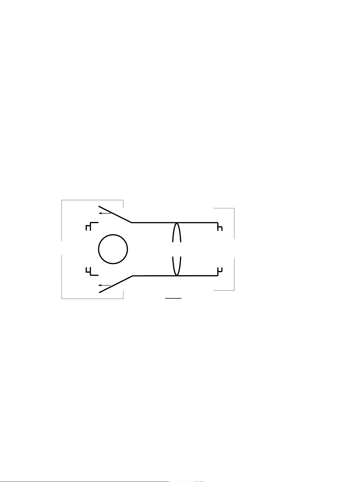
The light source is located in a specially constructed light box the top view of which is shown below:
• 2 Slit former plates
• 1 set of 8 color filters
• 1 Parabolic mirror
• 1 Lens biconvex small
• 1 Lens biconcave
• 1 Semi-circular slab
• 1 Prism 60° 30° 90°
• Spare Lamp
For Color
Experiments
Light
Source
Box
Collimatin
For Experiments
On Reflection &
R
n
Fig. 1
Study of colors: The source-end of the box is fitted with a light bulb and has one front opening and
two side openings. The side openings are fitted with mirrored doors to reflect the light emerging from
the openings. All three openings are constructed so as to allow the color filters (provided in the kit) to
be fitted into them. Then, by adjusting the mirrors, the reflected side-rays can be swung back and forth
to overlap the center-beam from the front opening. A colorful pattern can be obtained on a screen
placed in front of the center-opening about 15-20 cm from the light-box.
Study of reflection & refraction: The other end of the box also has an opening in which a slit plate or
a color filter can be fitted. Between the source and the opening is a collimating lens, the position and
effect of which can be changed by an adjusting knob on the top of the light-box. The rays emerging
from the opening are used to perform various experiments in reflection and refraction.
While performing the experiment: The results of an experiment are obtained best in darkness, as the
rays are most clearly visible then.
The collimating lens should be adjusted to give a converging, parallel or diverging beam of light, as
desired. For strong convergence (or divergence), a convex (or concave) lens could also be used.
1
Page 2
The optical devices (mirrors, lenses, prisms, slabs) should be handled by their finger-grips, so that no
smudges or scratches are inadvertently left on the optical faces. The bases of the lenses and prisms are
specially finished to provide a background for obscuring the path of light rays.
The optical accessory being used should be placed on a plain sheet of paper on which its outline can be
marked by running a pencil around its perimeter. Rays can be traced by marking two points on each
ray (incident on the accessory and emerging from it) as far apart as possible. Its path, within the
accessory, can be traced by joining the incident and emergent point by a straight line (after removing
the accessory). The direction of propagation can be indicated by arrowheads on the ray paths.
Possible problems and their remedies:
Faint secondary rays emerging from the light box: These are caused by reflections from the
support-wire of the filament and can be removed by rotating the bulb-holder (on top) by 180° so that
the support-wire lies behind the filament.
Internally reflected rays inside the device: Faint, secondary reflected rays (in the case of refracting
surfaces) are normal, as there is some light always reflected at such surfaces, and can be neglected.
Sometimes, rays enter the device from above and reflect off the vertical surfaces, giving erroneous
results. These can be removed by
• Blanking off the top of the slits to shorten the rays (not very helpful).
• Moving the entire set-up farther from the light-box.
• Placing the entire set-up slightly higher than the surface on which the light-box rests.
Experiments with colors
The source end of the light-box is to be used for experiments in this section. Filters can be fitted in the
three openings and the mirrors can be adjusted so that a rich mixing of colors takes place on a screen
placed in front of the center-opening.
Colors of objects:
• Close the side-openings (use the mirrors) and one by one, place the filters in the center-opening
and observe the color on the screen in front of it. This will familiarize you with the various colors.
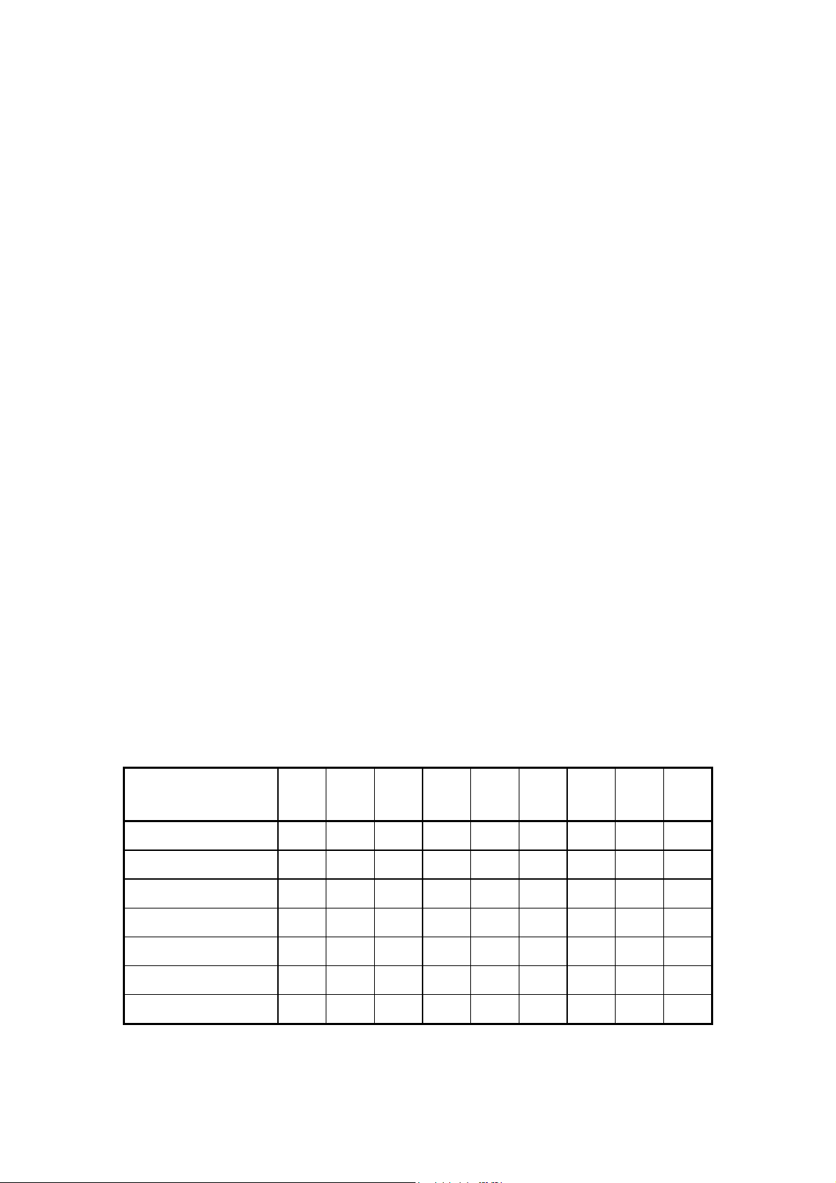
Next place cards on the screen and observe their colors in lights of different colors. Note your
observations in a table of the form:
Color of light falling on
plate →
Color of plate ↓
R
W R M O Y G C B V
M
O
Y
G
C
V
Index: W-White, R-Red, M-Magenta, O-Orange, Y-Yellow, G-Green, C-Cyan, B-Blue, V-Violet
• Next, observe these cards through colored filters and tabulate your results in a similar manner
2
Page 3

Color of filter used →
Color of plate in white
light ↓
R
W R M O Y G C B V
M
O
Y
G
C
V
Index: W-White, R-Red, M-Magenta, O-Orange, Y-Yellow, G-Green, C-Cyan, B-Blue, V-Violet
• After familiarizing yourself with the different colors, perform some experiments on your own by
observing a color card illuminated by light of one color and viewed in another color. Try to predict
your observation before performing the experiment.
Color Combinations: By using the side-openings, up to three colors can be projected onto the screen.
Place the weakest color filter in the center-aperture and the stronger ones on the sides so that intensity
loss (due to reflection) is compensated.
Initially, take any set of filters and note down the different colors formed by their overlapping.
Next, try to find COMPLEMENTARY COLORS, i.e., combinations that reproduce white light. Note
down the colors and their complement (the complement of color A is the color, which on combining
with it gives white light).
Shadows: Remove the filters and close the side-openings. Place a pencil in front of the screen. A sharp
shadow within a faint one can be observed. If the faint shadow is too faint, use a tracing-paper to
diffuse the light coming from the light box.
The sharp shadow is called the UMBRA and is the region where no light falls. The faint shadow
enclosing the umbra is the PENUMBRA, the region where partial light falls.
The phenomenon of umbra-penumbra can also be observed in everyday-life in your own shadow.
Try to explain the phenomenon with a ray diagram.
Colored Shadows: Place a set of complementary colors in the openings and adjust the mirrors to
obtain the white light on the screen. Place a pencil in a patch illuminated by all three colors and
observe the shadows formed. Shift the pencil to patches illuminated by all three colors and observe the
shadows formed. Shift the pencil to patches illuminated by two colors and then by one color and
observe the shadows. The number of shadows formed is the same as the colors illuminating the patch,
while their colors are the same as a few of the patches.
The above phenomena occur with any set of colors (not necessarily complementary). Try to explain the
number of shadows and their colors. (A ray diagram will prove helpful here, too.)
Experiments on Reflection:
Reflection is a phenomenon where light falling on a surface bounces back, in accordance with the
following laws:
1. The angle of reflection is equal to the angle of incidence.
3
Page 4

2. The incident ray, normal ray and reflected ray, all lie in the same plane.
Besides these laws, there are other important features of reflection that we come across every day, i.e.,
lateral inversion, shaving mirrors, rear-view mirrors etc.
Reflection from a Plane Mirror: Adjust the collimating lens so that the resultant beam of light is
parallel. Allow a single ray to pass out of the light-box (use a slit plate). Mark its position on the paper.
Place the plane mirror in its path, at an angle. Mark the position of the mirror and that of the reflected
ray. Remove the mirror and draw a normal to the outline of the mirror at the point where the incident
and reflected ray meet the outline. Measure the angles between the normal and incident rays and
normal and reflected rays to obtain the angles of incidence and reflection. Check that the FIRST LAW
OF REFLECTION is verified.
Next, replace the slit plate by the multiple slit plate with three or four slits. As above, place the mirror
in the path of the rays and measure the various angles of incidence and reflection.
Next, place a concave (or convex lens) in the path of the rays to obtain diverging (or converging) rays
falling on the mirror. After plotting their paths, measure the various angles, and answer the following
questions:
• Do these observations match with what you expected?
• What happens to the parallel, converging and diverging rays after they are reflected?
Reflected Images in a Plane Mirror: Set up the apparatus so that multiple converging rays fall on the
mirror. On looking into the mirror, you will see that the incident rays and the images of the reflected
rays appear to form the complete straight line paths of the incident rays (and vice-versa). This can be
verified by lifting the mirror and observing the real converging rays.
• Are the image of the reflected focus and the real focus (in the absence of the mirror) the same
point?
• Join the real and reflected foci by a straight line. What angle does it make with the mirror?
• Why is the image of the reflected rays fainter than the actual rays observed by removing the
mirror?
Lateral Inversion: When you look at an object and then at its image in a mirror, the two are observed
not to be identical.
• What is different about them?
The above phenomenon is called lateral inversion.
Remove all slit-plates from the light-box and adjust the collimating lens for a parallel beam of light.
Stand a pencil in the left (or right) corner of the opening and then look at the image in the mirror.
Where does the pencil stand?
• From the above experiment can you explain why lateral inversion occurs?
Place a multiple slit-plate in the opening so that four parallel rays fall on the mirror. Hold the red filter
in front of two slits and the violet filter in front of the other two so that the two inner rays are stopped
by the filter frames and the outer rays are of different colors. Observe the image.
• Are the rays from the left side of the light-box and the image on the left side the same color?
Look at yourself in a plane mirror. Do you observe any vertical inversion?
• Why does vertical inversion not occur?
If you observe the image of the word MAXAYAXAM in the mirror, what do you expect to see?
4
Page 5

Similarly, if you place the mirror on the dotted line and look at the image of the word below from the
bottom of the page, what do you see?
-------------------------- DI-OXIDE
An object is said to be SYMMETRICAL about an axis parallel to the mirror surface if the two halves
of the object are mirror images of each other.
• Are the above bold words symmetrical? If so, about which axes?
Multiple Reflections - Single Mirror: This experiment requires knowledge of refraction.
Allow a single ray to fall on the plane mirror placed very close to the light-box. Examine the reflected
rays closely.
• How many rays do you observe? Which one is the brightest and which one is the faintest?
• Explain how the images occur?
(HINT: Use the theory of refraction and the fact that the reflecting surface of the mirror is at the
back).
• What happens to the rays as the angle of incidence is
- Decreased from 45° to 0 °?
- Zero?
- Increased from 45 °to 90°?
To study an angle of incidence of 90°, place the mirror so that its side completely covers the slit
and the mirror is parallel to the ray.
• What do you observe at the other side of the mirror?
Rotate the mirror keeping the slit covered by one end of the mirror at all times. What happens?
The above phenomenon is used in OPTICAL FIBERS where light follows a curved path within the
fiber.
Shift the mirror forward and allow the ray to fall on the side of the mirror and observe the mirror from
above.
• How does the above phenomenon occur?
(HINT: Internal reflection)
Multiple Reflections - Multiple Mirrors: Borrow a plane mirror from another light box set. Place the
two mirrors at right angles to each other. Allow a single ray to fall on one of the mirrors. Observe the
ray reflected from the other mirror - it should be parallel to the incident ray.
• Using geometry, explain why this should be so.
• Is this true for all angles of incidence?
• Look into the corner of the mirrors. What do you observe?
If a large plane mirror is available, place it on the table with these two mirrors on it so that all are
mutually pair-wise perpendicular.
• What do you observe in the triple corner?
The above experiment was performed successfully on the moon as well.
• What can you say about the nature of light?
Examine the reflectors at the back of a car. What shape are the dimples in them?
5
Page 6
Ref
Rotation of a Plane Mirror: Aim a single ray at the mirror and note the incident ray, mirror position
and reflected ray. Rotate the mirror slightly around the incident point and reflected ray. Measure the
angle of rotation of the mirror (∠M) and that of the reflected ray (∠R). Repeat this for different angles.
• Derive a relation between ∠M and ∠R.
The above method is used in various instruments to amplify small changes.
Concave Mirror - Focus, Center of Curvature:
• Aim a set of parallel rays at the center of the mirror such that they are parallel to the mirror’s axis
of symmetry. Note the point where they converge - this is the FOCUS. The distance of the focus
from the center of the mirror is called the FOCAL LENGTH (f). The center of curvature lies at a
distance of 2f from the mirror along this line. The distance of 2f is the radius of curvature, ‘r’ of
the mirror.
• Place a concave lens (of short focal length) in front of the slits to produce diverging rays. Shift the
mirror until the reflected rays retrace their paths. The CENTER OF CURVATURE is the point
where the incident rays appear to diverge from and the RADIUS OF CURVATURE is the distance
of the point from the mirror.
• If, in the above experiment, you are unable to obtain a position where the reflected rays retrace
themselves, use
2111
=+=
rvuf
where, f = focal length of the mirror
u = distance between the mirror and the point from where incident rays appear to diverge
v = distance between the mirror and the point where reflected rays meet
(All distances are measured along the axis of symmetry)
lections From a
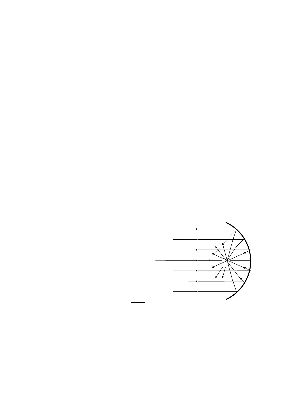
Concave Mirror - Caustic Curve:
SPHERICAL ABERRATION is the phenomenon in which parallel rays far away from the center of
the mirror do not focus onto the same point as those near the center, giving a distorted image.
To study aberration, allow four parallel rays to fall on the mirror and mark the points where two
adjacent rays meet. Shift the light-box to obtain another set of parallel rays, ensuring that the new set is
parallel to the old one and do the same. Join these points free-hand to obtain a curve called the
CAUSTIC CURVE.
Spherical Concave
Mirror
Fig. 2
X
C F
• What causes the caustic curve?
6
Page 7

P
F C
• Are the angles of incidence equal to the angles of reflection?
The above problem of improper focusing can be resolved by using a Paraboloid (instead of spherical)
or parabolic (instead of circular) mirror.
The caustic curve can also be obtained by allowing light from a bulb to fall directly onto the mirror.
Parabolic Mirror: In a parabolic mirror, distant as well as near rays focus at the same point.
M
Fig. 3
Spherical
Aberration
S
Reflections From a
arabolic Mirror
Fig.
Perform the same experiment as for obtaining the caustic curve.
• Do you obtain another curve or only a point?
• What types of mirrors are used in car headlights, torches, astronomical telescope reflector, etc?
• In the above question, where in relation to the reflector is the radiating device placed?
Convex Mirror - Focus, Center of Curvature: Aim a set of parallel rays onto the mirror. The point
from which the reflected rays appear to be diverging is its focus (can be obtained by extrapolating the
paths of the reflected rays) and the distance of the point from the mirror is the focal length ‘f’.
7
Page 8

CX’F
Q
X
Reflections From
A Spherical
Convex Mirror
Fig.
• Place a convex lens (of short focal length) in front of the slits and adjust the convex mirror beyond
it until the reflected rays coincide with the incident rays. Draw back these rays to the point where
they appear to meet. This point is the center of curvature of the mirror and the distance of this
point from the mirror is the radius of curvature (r).
P
L M
Fig. 6
• In case co-incidence is not obtained above use the relationship
2111
=+=
rvuf
where, f and r are already defined;
u = distance between mirror and point where incident rays appear to meet; and
v = distance between mirror and point where reflected rays appear to meet
Experiments on Refraction:
The basic law of refraction is
Where, µ = refractive index of the medium into which light refracts with respect to the medium the
light is incident from
i = angle of incidence; and
r = angle of reflection
Measurement of
slab. If the emergent ray is deflected, shift the slab (keeping it perpendicular to the incident ray at all
µ - Semi-circular Slab: Allow a single ray to fall normally on the flat side of the
sin
µ
.
=
risin
8
Page 9

times) until the emergent ray is not deflected. Mark the point of incidence - this is the center of
irN
N
curvature.
Shift the light-box so that a single ray strikes the same point of incidence at an angle other than 90°.
For different incident angles, mark the rays and half-chords on a circle drawn with the point of
incidence at its center.
1
2
3
Half Chord
3
2
1
Fig. 7
sin
is the same as
risin
i chord Half
, as both angles have the equal length hypotenuses. Hence, µ can be
r chord Half
calculated from the following table:
Ray no.
∠i ∠r
Half-chord i Half-chord r sin i sin r
µ =
sin
Semi-Circular
Slab
=
risin
i c-h
r c-h
Does any refraction occur at the circular face of the slab? Why/why not?
•
Measurement of µ - Parallel-sided Slab: Allow a single ray to fall on a parallel-sided slab at an angle
other than 90°. The (i
while the (i
) angle determine the refractive index of air with respect to acrylic plastic. Measure the
2-r2
values for different incident angles and calculate the mean refractive indices for both surfaces.
) angle determine the refractive index of acrylic plastic with respect to air
1-r1
What do you expect the product of the two refractive indices to be (theoretically)? What is it
•
actually?
Are the incident and emergent rays parallel?
•
9
Page 10

i
1
Incident Ray
i
2
r
1
t
d
r2
Fig. 8
Emergent Ray
Displacement, Parallel-sided Slab:
In the previous experiment, ‘d’ in the diagram is the displacement
of the emergent ray. For a given angle of incidence, this displacement is directly proportional to the
thickness, ‘t’ of the slab.
Allow a single ray of light to fall on the shorter side of the slab. Plot the emergent ray on the opposite
side and measure d. Also measure the length of the slab, t, and find the ratio d/t. Now, allow the ray to
strike the longer side of the slab at the same incident angle and measure d and t (in this case, width of
the slab) and find their ratio. Use other slabs of the same material and do the same. Is d/t the same in all
cases?
Apparent Depth, Parallel-sided Slab
Incident Ray
i1
Apparent Depth
i2
r
1
Real Depth
r2
Emergent Ray
Fig. 9
10
Page 11

µ of the slab can also be found by the apparent depth method.
(
)
µ = real depth/apparent depth. (This is strictly true only when i
This phenomenon is observed in day-to-day life when an underwater object appears to be closer to the
surface than it actually is.
Angle of Minimum Deviation: Allow a single ray to strike a face of a prism and emerge from another
face. Rotate the prism until minimum deviation is reached - the position of the prism in which the
emergent ray is least deviated from the incident ray path. Mark the outline of the prism and the rays.
Denote the angle enclosed by the two sides to be A.
+
DA
2
A
()
sin
2
Then,
sin
=
µ
is close to 90°)
1
i
Measure µ by the above formula and by (sin i
Repeat the experiment by using different prisms so that different A’s are used.
Are i
•
Is D equal to {(i
•
and r2 equal? Are i2 and r1 equal (at minimum deviation)?
1
)-(i2+r1)}?
1+r2
1
A
D
r
i
r
2
1
2
Fig. 10
/sin r1) and (sin r2/sin i2). Are they the same?
1
Total Internal Reflection - Semi-circular Slab: Allow a single ray to strike the semi-circular face
normally (if the ray within the slab is undeviated, then the incident ray is normal). This ray will strike
the flat face at its central point. Rotate the slab about this point until the ∠r = 90°. As ∠r approaches
90°, it is noticed that the ray reflected from the flat face increases in intensity while the refracted ray
becomes weaker. At ∠r = 90°, the refracted ray completely disappears while the reflected ray is very
strong.
11
Page 12

i
r = 90°
r
1
Fig. 11
The refractive index of the slab is calculated by
sin
µ
sin
1
==
iirsin
The ∠i at this point is called the CRITICAL ANGLE of the medium and is the minimum angle of
incidence for which all light is reflected back into the optically denser substance, instead of emerging
into air.
What do you expect ∠r
•
The critical angle for water to air is 49°. By what angle should a fish rotate its head to see the
•
to be? What is it actually?
1
riverbank, if it initially sees the opposite river-bank?
Total internal reflection is used in the OPTICAL-FIBER technology, a well-developed method of
transporting light and other electromagnetic waves.
Total Internal Reflection – Prism:
using any of the prisms.
The phenomenon of total internal reflection can be observed by
The 45°45°90° prism is a prism that can invert images and even reverse the direction of light.
1
3
2
2
3
1
Fig. 12
12
Page 13

The other prisms can also be experimented with. Try to obtain at least five positions of the three prisms
(besides the above two), which result in internal reflection. Trace the ray diagrams, using different
color pencils for different rays.
Try to set up the three prisms in such a manner that three rays are reflected internally by all three
•
prisms. (Optical-fiber technology is all about repeated total internal reflection).
Many faint rays are seen while examining total internal reflection. What could be the reasons for
•
these rays?
Mirages are an effect of total internal reflection. Can you explain how?
•
45°45°90° prisms are used in their light-reversing modes to shorten the length of telescopes.
Fig. 13
Fig. 14
13
Page 14

F
Dispersion of Colors: Allow a wide beam of light to be incident on one face of the equilateral prism.
On a white screen, observe the emergent spectrum for different angles of deviation (from minimum
deviation to near-internal reflection).
What difference is there between the spectra obtained at minimum deviation and near-internal
•
reflection? (Hint: How many colors are seen in each case?) Why?
Would you say that µ is the same r all colors? If not, arrange the colors in order of increasing µ.
•
A prism is just a parallel-slab cut diagonally. Why, then, is there no dispersion of colors in a slab?
•
Rain-drops are shaped like prisms. Hence, they also disperse colors and form colorful rainbows.
In the above experiment, study the effect of placing filters of different colors, along with the slitformer.
Focus - Convex Lens: Allow parallel rays to fall on the convex lens parallel to its axis of symmetry.
These rays meet (after refraction) at the FOCUS. The distance, OF, is the focal length (f) of the lens.
O
Fig.
Place a diverging lens in front of the slits so that diverging rays fall on the convex lens.
The focal length (ignoring signs) is then given by
111
+=
uvf
Where, f = focal length of the convex lens
v = OV where V is the point the rays meet
u = OU where U is the point from which the incident rays appear to be diverging from
14
Page 15

Focus - Concave Lens:
F
Allow a set of parallel rays to fall on the concave lens parallel to its axis of
symmetry. The rays diverge after refraction. The point from which they appear to diverge is the focus
(F) of the lens and OF is the focal length (f).
O
Fig. 16
Theoretically, the focal length of a concave lens can be calculated by many methods. Some of them are
shown in Appendix 1. However, these methods are not very reliable with the light-box apparatus.
Which lens would you use to remedy myopia (short/near-sightedness)? Which one for
•
hypermetropia (long/far-sightedness)? Explain.
Focal Plane: Allow two parallel rays to fall on a convex lens near the lens center and mark their focus.
Changing the angle of incidence, but keeping the points of incidence the same, mark the foci for
several sets of two parallel rays. Join these loci to obtain a straight line, referred to as FOCAL LINE.
(In spherical lenses, a plane is obtained called the FOCAL PLANE).
The concept of the focal plane is used in designing cameras and telescopes.
Radius of Curvature: Every lens has two radii of curvature, r
and r2.
1
By tracing the curve of one side of the lens, r
tracing and trace further. Repeat this till a complete circle is formed. The radius of this circle is r
doing the same for the other curved surface, r
can be obtained. Shift the curved surface along this
1
can be obtained.
2
. By
1
Having found r
and r2 for a lens, find its focal length by the LENSMAKER’S EQUATION :
1
1
()
1
µ
11
+−=
rrf
21
Calculate the focal length for both the convex lens and the concave lens by this equation (take the
mean value of µ obtained in the prism and slab experiments - the lenses are also made of acrylic
plastic).
Are the calculated focal lengths in agreement with what you observed in previous experiments?
•
15
Page 16

Spherical Aberration:
symmetry. The inner two and outer two rays meet at different foci. This defect is called spherical
aberration.
Allow four parallel rays to strike a convex lens, parallel to its axis of
In the figure the parallel rays striking the lens near the edge are bent to a nearer focus, B, than those
passing through near the center, which meet at A. The magnitude of the defect, represented by AB in
the diagram, is shown greatly exaggerated.
As for the concave mirror, plot the caustic curve for a convex lens (The curve is called a semi-
•
cubical parabola)
Chromatic Aberration: Since the refractive index is different for different colors, they will have
different foci. This defect is called chromatic aberration. Chromatic aberration can be corrected by
combinations of lenses of different types of glass (combinations are chosen so as to simultaneously
reduce spherical aberration).
Fig. 17
B
A
White
Lens
16
Blue
Fig. 18
Red
Red
White
Page 17

In the set-up for spherical aberration, block the two inner rays and observe the colored foci obtained
closely.
Which color has the shortest focal length? Is this in agreement with the dispersion obtained by a
•
prism? (Consider the lens as two prisms placed end-on-end).
For more information on aberrations, see Appendix 2.
Appendix 1: Determination of Focal Length of a Concave Lens
Method 1:
its position. Let the source be S
the divergent lens at a point O
the screen. The distances required are O
diverging lens. The rays are directed to S
notation described,
Throw the image of a source of light by means of a converging lens on to a screen and note
and let the image formed by the converging lens at O1 be at S2. Place
1
so that the image is displaced from S2 to S3, where it is again located on
2
and O2S3 for S2 and S3 are conjugate points for the
2S2
so that S2 is a virtual object and in accordance with the
2
S2 S
S1
O
1
O
2
Fig. 19
Here, L = -O
2S2
L’ = O2S3
1
The formula
=+
, then gives the value of f, which in this notation will be of negative sign.
fLL11'
The experiment should be repeated for different positions of O
for different positions of the convergent lens relative to S
, while S1 and O1 remain fixed, and also
2
.
1
Method 2:
Another method for the determination of the focal length of the diverging lens requires the
above apparatus with a plane mirror in addition.
The diagram illustrates the method. If the rays from the concave lens strike a plane mirror placed at any
point, M, to the right of it at normal incidence, they are returned to form an image at the source, S
. In
1
these circumstances the rays from the convex lens are directed towards the principal focus, F, of the
3
17
Page 18

concave lens. The procedure is to focus the rays from the source by means of the lens, O1, and to locate
the image, F. The concave lens is then placed between O
until an image of S
is thrown back as close as possible to S1 itself. For this purpose it is convenient to
1
and the mirror and moved along the axis
1
place a source of light behind a small hole on a white screen, and to use the hole as a source so that the
image may appear on the screen close beside the hole. The mirror, M, may be placed in contact with
the concave lens and they may be held together by means of an elastic band. From the diagram, clearly
the focal length of the concave lens must be less than the distance, O
F. Thus the return of rays in this
1
way cannot be obtained for every position of the convex lens with respect to the source. It is a matter
for trial in the first instance, to ensure that the image distance, O
distance, O
, should be made a little greater than the focal length of the convex lens in order that the
1S1
image may be thrown on a screen placed at a sufficient distance to the right of O
and mirror should then be moved from this screen towards O
. This will then give the magnitude of the focal length required, and a series of measurements may be
S
1
obtained by variations of the distance, O
, within certain limits.
1S1
F, is sufficiently great and the object
1
. The concave lens
1
until an image appears on the screen at
1
S1
O
1
O
2
F
M
Fig. 20
’P
M
Fig. 21
18
Page 19

Method 3:
will be seen on looking through the lens, and it may be made to coincide with the pin by suitably
adjusting the mirror.
Set up a concave mirror behind the lens and a pin in front. An inverted image of the pin
Appendix 2: The Aberration of Lenses
Under ordinary circumstances, a lens or a system of lenses will not produce a perfect image. The
defects of the image arise in various ways from geometrical causes as well as from the physical
properties of glass, and they become especially troublesome when the lens is used at a large relative
aperture to cover a wide field of view. Except in unusual cases, lens designers are concerned with six
types of aberrations, two of which are briefly described below.
It is impossible to correct a system of lenses for all aberrations at the same time. Sometimes the process
of eliminating one defect intensifies another. Furthermore, a lens designed to give good images of
objects at one distance will give imperfect image at others. Hence it is impossible to design a
universally useful lens; each problem in lens design requires individual study. If an exceedingly sharp
image is required, the system needs especially fine spherical and chromatic correction; and this can
only be achieved by sacrificing the field of view to reduce the aberrations known as coma and
astigmatism. A wide-angle photographic lens, on the other hand, calls for freedom from coma and
astigmatism, and then the aperture of the lens must remain small to avoid spherical and chromatic
errors. This explains why wide-angle lenses rarely have relative apertures (values of D/f) greater than
1/10, while ordinary photographic lenses with smaller fields of view may have relative apertures as
high as 1/1.5.
Spherical Aberration:
and the object is on the axis of the lens, and light of only one color is used. It is a property of lenses
with spherical surfaces that rays from a point on the axis are not brought together at a single point
focus unless the lens has a very small relative aperture.
The magnitude of spherical aberration is proportional to the square of the relative aperture for lenses of
the same focal length, or to the focal length of the lenses of the same relative aperture. For all sorts of
lenses, the magnitude is proportional to the square of the diameter divided by the focal length. The
magnitude also varies with the shape of the lens. For a simple lens of 10cm diameter and 100cm focal
length (relative aperture 1/10), the magnitude is 1.67cm if the lens is symmetrically double-convex;
4.5cm if the lens is plano-convex with the plane side toward the distant object; and 1.17cm if the plane
side is turned toward the image.
It is possible to avoid, or at least reduce, this problem in three ways.
Reduce the diameter of the lens, or place a diaphragm in the beam near the lens so as to cut out all
•
but the central rays. The amount of light transmitted by the lens is then greatly reduced. This is
usually undesirable.
Choose a lens of the best shape by combining lenses of different shapes. It is possible to combine a
•
strongly convergent lens of a shape producing a small amount of aberration with a weaker
diverging lens, which gives the same aberration in the opposite direction without at the same time
completely annulling the convergence of the rays produced by the first lens.
Abandon the spherical surface and grind the lens to a slightly different shape. Aspherical lenses
•
are sometimes used in spectacles, microscopes and projection lanterns.
Chromatic Aberration: The bending of light by a lens varies with the color. A simple lens, if it had
no other defects, would bring the blue range of white light to a nearer focus than the red. The yellow
This name is applied to the defect occurring in the image when the lens is large
19
Page 20

rays, which affect the eyes the most, come in between. A screen placed so as to catch the yellow focus
would show an image with a purple border, the edges being bluish.
The correction of this defect is accomplished by combinations of lenses of different sorts of glass. Flint
glass, for instance, spreads the colors apart more widely than does the crown glass. A diverging lens of
flint glass placed close to a converging lens can bring the spread colored rays back to parallelism.
20
 Loading...