

Page 1
3B SCIENTIFIC
1006784 / U8404248
Instruction Sheet
02/12 ELWE/ALF
®
PHYSICS
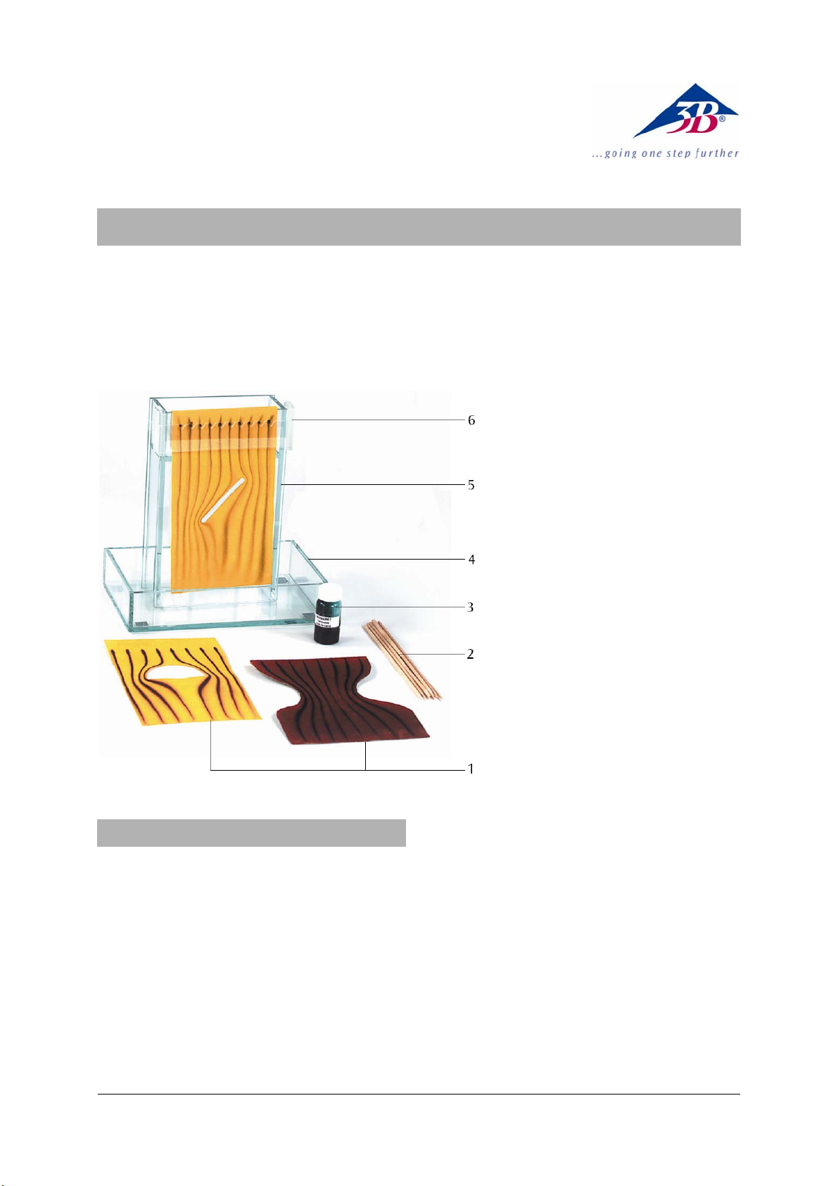
Laminar Flow Apparatus
1 Sheets of velour paper
2 Swad for the dye
3 Flask with dye
4 Acrylic glass basin, bottom
5 Acrylic glass basin, top
6 Mask
1. Description
The laminar flow apparatus can be used to demonstrate and examine the laminar flow in water.
It enables experiments which focus on the following
subjects:
Development of flow in water
Streamline curve of a linear laminar water flow
Streamline curve around objects with various
shapes
Streamline curve around a wing of an aero-
plane with different angles of attack
Streamline curve at a narrow point
The laminar flow apparatus consists of two cuboid
acrylic glass containers. The large container has a
separate floor, so that its top part can be filled with
water. The bottom container collects the overflowing
water. The water flows along rectangular sheets of
velour paper, whose top ends point into the large
container. The velour paper sheets have cut-outs,
which allow you to generate various flow curves. A
mask is put onto the velour paper. It contains cutouts which allow you to evenly mark the flow with
colour.
1
Page 2
2. Equipment supplied
2 Acrylic glass basins
1 Mask
20 Sheets of velour paper with cut-outs
1 Mini-flask with dye
Swab for dye
Rubber gloves
3. Technical data
Dimensions: approx. 220x140x240 mm3
Weight: approx. 1 kg
4. Operating principle
Due to the capillary effect and the weight of the
water, it is sucked out of the top container, slowly
and constantly flowing down the velour paper. At the
bottom end of the paper it drops down and is collected in the flat bottom container. In order to be
able to observe and record the streamline curve, the
water flow is marked with colour at regular intervals
near the top edge of the container filled with water.
When the flow is frequently coloured at these points,
the streamline curves are marked by the developing
colour lines. At the cut-outs in the velour paper, the
streamlines change. Due to the colour, the respective
paths of the flowing water are made visible. The
streamlines have their initial shape behind the blocking object. Due to the thin water layer and the
flow resistance of the fibres in the velour paper, the
flow velocity is limited to approx. 2 mm/s. It is therefore possible to easily observe how the streamline
images of the laminar flow develop. The equipment
is distinguished by its simple testing method, its easy
handling and a safe testing performance. It has the
special advantage that the developing streamline
images can be made permanent by drying the velour
paper sheets for later use.
5. Operation
• Fill the top part of the large glass container with
water up to a few millimetres below the top
edge.
• Then select the required velour paper sheet.
• Soak it with water by either letting water flow
over the paper or by completely dipping it into a
flat container filled with water.
• Bend back the top part of the velour paper, with
the velour side facing the observer.
• Suspend the folded part of the paper over the
edge of the wall of the acrylic glass vessel such
that it reaches well down into the water.
• Smooth out the front of the velour paper with
your hand to remove possible air bubbles between the wall and the paper.
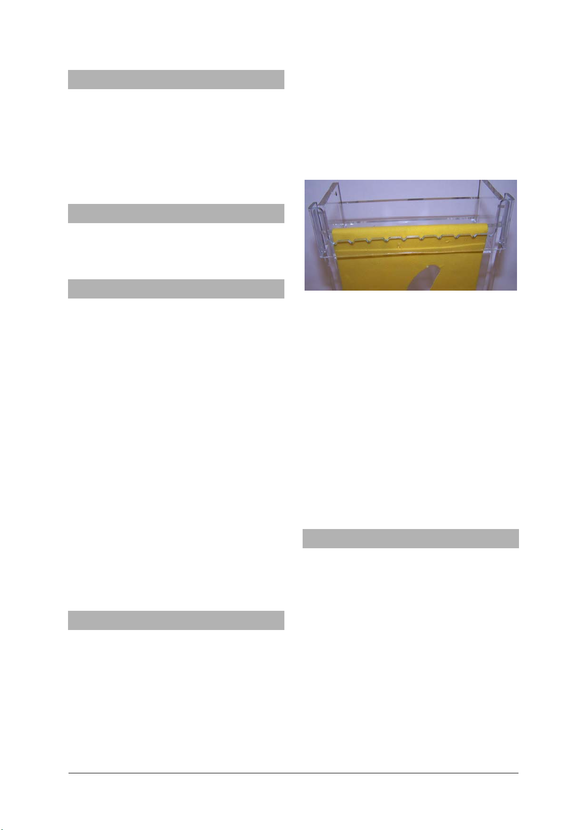
• Then put the mask over the velour paper sheet
onto the top container (refer to fig. 1).
Fig. 1
• Insert the swab into the bottle with the colour
solution. Then subsequently apply the colour to
the cut-outs on the mask. If there is not enough
colour, repeat this procedure.
• When using dyes be careful not to splash them
on clothing, for example.
Step by step, the respective streamline image develops on the velour paper.
• Then remove the mask, take the velour paper
out of the container and dry it, for example, by
hanging it on a horizontal cord.
Note: You may easily cut shapes yourself into the
respective pieces of velour paper. Any shape and
position for the object is possible. The velour paper
should be of a light colour.
6. Sample experiments
6.1. Streamline curve of a linear laminar flow
• Use the velour paper sheet without cut-outs.
The colour lines run vertically at regular intervals
(refer to fig. 2).
Result: In a linear laminar flow, all the streamlines
are parallel to each other. The direction and the
velocity of the flow are constant at any point.
6.2 Streamline curve around objects with various
shapes
• Use sheets of velour paper with cut-outs in the
form of a circle, semi-circle and a rectangle one
after the other.
In front of the object, the flow splits. The streamlines
move around the sides of the object. The intervals
between them reduce. The flow reassembles behind
the object. The individual streamlines run at regular
2
Page 3

intervals, as in front of the object (refer to fig. 3 a, b,
c).
Result: The flow object causes the flow to change its
direction in its close proximity. The velocity of the
flow increases and the streamlines move closer to
each other. Behind the object, the velocity of the
flow reduces. The interval between the streamlines
increases. Finally, the lines are parallel.
6.3. Streamline curve around a wing profile of an
aeroplane
• Carry out the experiment using a sheet of velour
paper with a wing-shaped cut-out.
Above the wing, the streamlines change their directions greatly and are compressed. Therefore, the
flow velocity is high. Below the wing, the flow velocity only increases slowly. Repeat the experiment with
the velour paper sheet, on which the angle of attack
is larger than zero. In the top area, the directions of
the streamlines change greatly. Below the wing pro-
file, the streamlines initially run in its direction and
are then drift down (refer to fig. 4 a, b).
Result: The streamline image of a wing profile shows
a great increase of velocity above the profile due to
the narrow streamlines. Below the wing, the fluid
flows in the direction of the wing when the angle of
attack is positive and then drifts down.
6.4. Streamline curve at a narrow point
• Use the velour paper sheet with the cut-outs on
both sides.
When the flow reaches the narrow point, its velocity
increases. The streamlines move together. After passing the narrow point, the streamlines move apart, so
that the flow shows its initial streamline curve (refer
to fig. 5).
Result: At a narrow point, the interval between the
streamlines reduces. The flow velocity increases
greatly. After the narrow point, the intervals between
the streamlines increase. The flow velocity reduces.
Fig. 2 Fig. 3 a, b c
3
Page 4

Fig. 4 a, b Fig. 5
Elwe Didactic GmbH ▪ Steinfelsstr. 5 ▪ 08248 Klingenthal ▪ Germany ▪ www.elwedidactic.com
3B Scientific GmbH ▪ Rudorffweg 8 ▪ 21031 Hamburg ▪ Germany ▪ www.3bscientific.com
Subject to technical amendments
© Copyright 2012 3B Scientific GmbH
 Loading...