


 Loading...
TOSHIBA Barcode Printer
B-SX4T SERIES
Owner’s Manual Mode d’emploi Bedienungsanleitung
Manual de instrucciones Gebruikershandleiding Manuale Utente
Manual do Utilizador
CE Compliance (for EU only)
This product complies with the requirements of EMC and Low Voltage Directives including their amendments.
VORSICHT:
•Schallemission: unter 70dB (A) nach DIN 45635 (oder ISO 7779)
•Die für das Gerät Vorgesehene Steckdose muß in der Nähe des Gerätes und leicht zugänglich sein.
Centronics is a registered trademark of Centronics Data Computer Corp.
Microsoft is a registered trademark of Microsoft Corporation.
Windows is a trademark of Microsoft Corporation.
This equipment has been tested and found to comply with the limits for a Class A digital device, pursuant to Part 15 of the FCC Rules. These limits are designed to provide reasonable rotection against harmful interference when the equipment is operated in a commercial environment. This equipment generates, uses, and can radiate radio frequency energy and, if not installed and sed in accordance with the instruction manual, may cause harmful interference to radio communications. Operations of this equipment in a residential area is likely to cause harmful interference in which case the user will be required to correct the interference at his own expense.
(for USA only)
Changes or modifications not expressly approved by manufacturer for compliance could void the user’s authority to operate the equipment.
“This Class A digital apparatus meets all requirements of the Canadian Interference-Causing Equipment Regulations.”
“Cet appareil numérique de la classe A respecte toutes les exigences du Règlement sur le matériel brouilleur du Canada.”
(for CANADA only)
N258 IP20
< For EU Only >
TOSHIBA TEC Europe Retail Information Systems S.A. Rue de la Célidée 33 BE-1080 Brussels
Copyright © 2006
by TOSHIBA TEC CORPORATION All Rights Reserved
570 Ohito, Izunokuni-shi, Shizuoka-ken, JAPAN

TOSHIBA Barcode Printer
B-SX4T SERIES
 Owner's Manual

Waste Recycling information for users:
Following information is only for EU-member states:
The use of the crossed-out wheeled bin symbol indicates that this product may not be treated as general household waste.
By ensuring this product is disposed of correctly you will help prevent
potential negative consequences for the environment and human health, which could otherwise be caused by inappropriate waste handling of this product. For more detailed information about the take-back and recycling of this product, please contact your supplier where you purchased the product.

This product is equipped with a wireless communication device,
TEC-RFID-US1 (B-9704-RFID-U1-US-R), TEC-RFID-EU1 (B-9704-RFID-U1-EU-R), TRW-USM-01 (B-SX704-RFID-U2-US-R) TRW-EUM-01 (B-SX704-RFID-U2-EU-R), TRW-AUM-01 (B-SX704-RFID-U2-AU-R)
Please be sure to read the enclosed precaution for handling of wireless communication devices before using this product. Precautions for Handling of Wireless Communication Devices
RFID kit:TEC-RFID-US1 (B-9704-RFID-U1-US-R), TEC-RFID-EU1 (B-9704-RFID-U1-EU-R), TRW-USM-01 (B-SX704-RFID-U2-US-R), TRW-EUM-01 (B-SX704-RFID-U2-EU-R), TRW-AUM-01 (B-SX704-RFID-U2-AU-R)
For all countries and areas
This product is a wireless communication device, and the use of this product is restricted to the following countries or areas. If the product is used in the countries or areas other than the following, you may be punished according to the laws of those countries or areas.
TEC-RFID-US1 (B-9704-RFID-U1-US-R), TRW-USM-01 (B-SX704-RFID-U2-US-R): USA, Canada
TEC-RFID-EU1 (B-9704-RFID-U1-EU-R), TRW-EUM-01 (B-SX704-RFID-U2-EU-R): Austria, Belgium, Cyprus, Czech Republic, Denmark, Estonia, Finland, France, Hungary, Germany, Greece, Ireland, Italy, Latvia, Lithuania, Luxembourg, Malta, Netherlands, Poland, Portugal, Slovakia, Slovenia, Spain, Sweden, United Kingdom, Norway, Liechtenstein, Iceland, Switzerland TRW-AUM-01 (B-SX704-RFID-U2-AU-R): Australia
For safety
Do not use the product in locations where the use is forbidden, for example in a hospital. When you do not know the forbidden areas, please refer to and follow the medical institution. Otherwise medical equipment may be affected, causing a serious accident.
This product may affect the operation of some implanted cardiac pacemakers and other medically implanted equipment. Pace maker patients should be aware that the use of this product very close to a pacemaker might cause the device to malfunction. If you have any reason to suspect that interference is taking place, immediately turn off the product and contact your TOSHIBA TEC sales agent.
Do not disassemble, modify, or repair the product.
Doing so may cause injury. Also, modification is against the Laws and Regulations for Radio Equipment. Please ask your TOSHIBA TEC sales agent for repair.
For USA
This device complies with Part 15 of the FCC Rules.
Operation is subject to the following two conditions:
(1)this device may not cause harmful interference, and
(2)this device must accept any interference received , including interference that may cause undesired operation.
Changes or modification not expressly approved by manufacturer for compliance could void the user’s authority to operate the equipment.
For Canada
Operation is subject to the following two conditions:
(1)this device may not cause interference, and
(2)this device must accept any interference , including interference that may cause undesired operation of the device.
For Europe
Hereby, Toshiba TEC Corporation, declares that this TEC-RFID-EU1 (B-9704-RFID-U1-EU-R), TRW-EUM-01 (B-SX704-RFID-U2-EU-R) are in compliance with the essential requirements and other relevant provisions of Directive 1999/5/EC. This equipment uses the radio frequency band which has not been harmonized throughout all EU and EFTA countries, and can be used in the following countries.
Austria, Belgium, Cyprus, Czech Republic, Denmark, Estonia, Finland, France, Hungary, Germany, Greece, Ireland, Italy, Latvia, Lithuania, Luxembourg, Malta, Netherlands, Poland, Portugal, Slovakia, Slovenia, Spain, Sweden, United Kingdom, Norway, Liechtenstein, Iceland, Switzerland
Safety Summary |
ENGLISH VERSION EO1-33058 |
Safety Summary
Personal safety in handling or maintaining the equipment is extremely important. Warnings and Cautions necessary for safe handling are included in this manual. All warnings and cautions contained in this manual
should be read and understood before handling or maintaining the equipment.
Do not attempt to effect repairs or modifications to this equipment. If a fault occurs that cannot be rectified using the procedures described in this manual, turn off the power, unplug the machine, then contact your authorised TOSHIBA TEC representative for assistance.
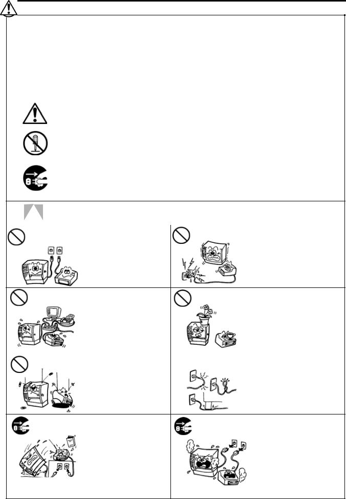
Meanings of Each Symbol
This symbol indicates warning items (including cautions).
Specific warning contents are drawn inside the  symbol. (The symbol on the left indicates a general caution.)
This symbol indicates prohibited actions (prohibited items).
Specific prohibited contents are drawn inside or near the  symbol. (The symbol on the left indicates “no disassembling”.)
This symbol indicates actions which must be performed.
Specific instructions are drawn inside or near the z symbol.
(The symbol on the left indicates “disconnect the power cord plug from the outlet”.)
|
|
WARNING |
This indicates that there is the risk of death or serious injury if the |
|
|||
|
|
|
|||||
|
|
machines are improperly handled contrary to this indication. |
|
||||
|
|
|
|
|
|
|
|
|
Any other than the |
Do not use voltages other than |
Prohibited |
Do not plug in or unplug the power |
|
||
|
|
|
cord plug with wet hands as this |
|
|||
|
specified AC voltage the voltage (AC) specified on the |
|
|||||
|
is prohibited. |
rating plate, as this may cause |
|
may cause electric shock. |
|
||
|
|
|
fire or electric shock. |
|
|
|
|
Prohibited |
If the machines share the same |
|
Prohibited |
Do not place metal objects or |
outlet with any other electrical |
|
water-filled containers such as |
||
|
appliances that consume large |
|
|
flower vases, flower pots or mugs, |
|
amounts of power, the voltage |
|
|
etc. on top of the machines. If |
|
will fluctuate widely each time |
|
|
metal objects or spilled liquid enter |
|
these appliances operate. Be sure |
|
|
the machines, this may cause fire |
|
to provide an exclusive outlet for |
|
|
or electric shock. |
|
the machine as this may cause |
|
|
|
|
fire or electric shock. |
|
|
|
Prohibited |
Do not insert or drop metal, |
|
Prohibited |
Do not scratch, damage or modify |
|
||||
flammable or other foreign |
|
the power cords. Also, do not |
||
|
objects into the machines through |
|
|
place heavy objects on, pull on, or |
|
the ventilation slits, as this may |
|
|
excessively bend the cords, as this |
|
cause fire or electric shock. |
|
|
may cause fire or electrical shock. |
Disconnect |
If the machines are dropped or |
Disconnect |
Continued use of the machines in |
|
their cabinets damaged, first turn |
an abnormal condition such as |
|||
the plug. |
the plug. |
|||
|
off the power switches and |
|
when the machines are producing |
|
|
disconnect the power cord plugs |
|
smoke or strange smells may cause |
|
|
from the outlet, and then contact |
|
fire or electric shock. In these |
|
|
your authorised TOSHIBA TEC |
|
cases, immediately turn off the |
|
|
representative for assistance. |
|
power switches and disconnect the |
|
|
Continued use of the machine in |
|
power cord plugs from the outlet. |
|
|
that condition may cause fire or |
|
Then, contact your authorised |
|
|
electric shock. |
|
TOSHIBA TEC representative for |
|
|
|
|
assistance. |
( i )
Safety Summary |
ENGLISH VERSION EO1-33058 |
|
|
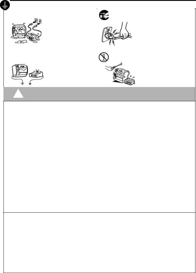
Disconnect |
If foreign objects (metal |
Disconnect |
When unplugging the power cords, |
|
|
||||
|
|
fragments, water, liquids) enter |
be sure to hold and pull on the plug |
||
|
|
the plug. |
the machines, first turn off the |
the plug. |
portion. Pulling on the cord portion |
|
|
|
power switches and disconnect |
|
may cut or expose the internal wires |
|
|
|
the power cord plugs from the |
|
and cause fire or electric shock. |
|
|
|
outlet, and then contact your |
|
|
|
|
|
authorised TOSHIBA TEC |
|
|
|
|
|
representative for assistance. |
|
|
|
|
|
Continued use of the machine in |
|
|
|
|
|
that condition may cause fire or |
|
|
|
|
|
electric shock. |
|
|
|
|
Connect a |
Ensure that the equipment is |
No |
Do not remove covers, repair or |
|
|
properly grounded. Extension |
modify the machine by yourself. |
||
|
|
grounding wire. |
disassembling. |
||
|
|
|
cables should also be grounded. |
|
You may be injured by high |
|
|
|
Fire or electric shock could |
|
voltage, very hot parts or sharp |
|
|
|
occur on improperly grounded |
|
edges inside the machine. |
|
|
|
equipment. |
|
|
|
|
|
|
|
|
CAUTION This indicates that there is the risk of personal Injury or damage to objects if the machines are improperly handled contrary to this indication.
Precautions
The following precautions will help to ensure that this machine will continue to function correctly.
• Try to avoid locations that have the following adverse conditions: |
* |
High humidity |
|||
* |
Temperatures out of the specification |
* |
Direct sunlight |
||
* |
Shared power source |
* |
Excessive vibration |
* |
Dust/Gas |
•The cover should be cleaned by wiping with a dry cloth or a cloth slightly dampened with a mild detergent solution. NEVER USE THINNER OR ANY OTHER VOLATILE SOLVENT on the plastic covers.
•USE ONLY TOSHIBA TEC SPECIFIED paper and ribbons.
•DO NOT STORE the paper or ribbons where they might be exposed to direct sunlight, high temperatures, high humidity, dust, or gas.
•Ensure the printer is operated on a level surface.
•Any data stored in the memory of the printer could be lost during a printer fault.
•Try to avoid using this equipment on the same power supply as high voltage equipment or equipment likely to cause mains interference.
•Unplug the machine whenever you are working inside it or cleaning it.
•Keep your work environment static free.
•Do not place heavy objects on top of the machines, as these items may become unbalanced and fall causing injury.
•Do not block the ventilation slits of the machines, as this will cause heat to build up inside the machines and may cause fire.
•Do not lean against the machine. It may fall on you and could cause injury.
•Care must be taken not to injure yourself with the printer paper cutter.
•Unplug the machine when it is not used for a long period of time.
•Place the machine on a stable and level surface.
Request Regarding Maintenance
•Utilize our maintenance services.
After purchasing the machine, contact your authorised TOSHIBA TEC representative for assistance once a year to have the inside of the machine cleaned. Otherwise, dust will build up inside the machines and may cause a fire or a malfunction. Cleaning is particularly effective before humid rainy seasons.
•Our preventive maintenance service performs the periodic checks and other work required to maintain the quality and performance of the machines, preventing accidents beforehand.
For details, please consult your authorised TOSHIBA TEC representative for assistance.
•Using insecticides and other chemicals
Do not expose the machines to insecticides or other volatile solvents. This will cause the cabinet or other parts to deteriorate or cause the paint to peel.
(ii)
ENGLISH VERSION EO1-33058
|
|
|
TABLE OF CONTENTS |
|
|
|
|
|
Page |
1. |
PRODUCT OVERVIEW......................................................................................................... |
E1- 1 |
||
|
1.1 |
Introduction................................................................................................................... |
E1- 1 |
|
|
1.2 |
Features ....................................................................................................................... |
E1- 1 |
|
|
1.3 |
Unpacking..................................................................................................................... |
E1- 1 |
|
|
1.4 |
Accessories ................................................................................................................. |
E1- 2 |
|
|
1.5 |
Appearance .................................................................................................................. |
E1- 3 |
|
|
|
1.5.1 |
Dimensions................................................................................................................ |
E1- 3 |
|
|
1.5.2 |
Front View ................................................................................................................. |
E1- 3 |
|
|
1.5.3 Rear View.................................................................................................................. |
E1- 3 |
|
|
|
1.5.4 |
Operation Panel......................................................................................................... |
E1- 4 |
|
|
1.5.5 |
Interior ....................................................................................................................... |
E1- 4 |
|
1.6 |
Options ................................................................................................................................ |
E1- 5 |
|
2. |
PRINTER SETUP .................................................................................................................. |
E2- 1 |
||
|
2.1 |
Installation .................................................................................................................... |
E2- 2 |
|
|
2.2 |
Fitting the Fan Filter...................................................................................................... |
E2- 3 |
|
|
2.3 |
Connecting the Power Cord ......................................................................................... |
E2- 3 |
|
|
2.4 |
Loading the Media ........................................................................................................ |
E2- 4 |
|
|
2.5 |
Loading the Ribbon ...................................................................................................... |
E2- 9 |
|
|
2.6 |
Connecting the Cables to Your Printer ........................................................................ |
E2-11 |
|
|
2.7 |
Turning the Printer ON/OFF ........................................................................................ |
E2-12 |
|
|
|
2.7.1 |
Turning ON the Printer ............................................................................................. |
E2-12 |
|
|
2.7.2 |
Turning OFF the Printer............................................................................................ |
E2-12 |
|
2.8 |
Inserting the Optional PCMCIA Cards......................................................................... |
E2-13 |
|
|
2.9 |
Setting an Operating Environment .............................................................................. |
E2-14 |
|
|
|
2.9.1 |
Parameter Setting..................................................................................................... |
E2-15 |
|
|
2.9.2 Dump Mode Setting.................................................................................................. |
E2-32 |
|
|
|
2.9.3 BASIC Expansion Mode ........................................................................................... |
E2-34 |
|
|
2.10 |
Installing the Printer Drivers ........................................................................................ |
E2-35 |
|
|
|
2.10.1 |
Introduction............................................................................................................. |
E2-35 |
|
|
2.10.2 |
General Description................................................................................................ |
E2-35 |
|
|
2.10.3 |
Installing the Printer Driver ..................................................................................... |
E2-36 |
|
|
2.10.4 |
Uninstalling the Printer Driver................................................................................. |
E2-49 |
|
|
2.10.5 |
Adding/Deleting a LAN Port.................................................................................... |
E2-50 |
|
|
2.10.6 |
Cautions ................................................................................................................. |
E2-52 |
|
|
2.10.7 |
Using the Printer Driver .......................................................................................... |
E2-53 |
|
2.11 |
Print Test ..................................................................................................................... |
E2-54 |
|
|
2.12 |
Position and Print Tone Fine Adjustment ................................................................... |
E2-56 |
|
|
2.13 |
Threshold Setting ........................................................................................................ |
E2-64 |
|
3. |
ON LINE MODE..................................................................................................................... |
E3- 1 |
||
|
3.1 |
Operation Panel............................................................................................................ |
E3- 1 |
|
|
3.2 |
Operation...................................................................................................................... |
E3- 2 |
|
|
3.3 |
Reset |
............................................................................................................................ |
E3- 2 |
ENGLISH VERSION EO1-33058
|
|
|
|
Page |
4. |
MAINTENANCE .................................................................................................................... |
E4- 1 |
||
|
4.1 |
Cleaning ....................................................................................................................... |
E4- 1 |
|
|
|
4.1.1 |
Print Head/Platen/Sensors ........................................................................................ |
E4- 1 |
|
|
4.1.2 Covers and Panels .................................................................................................... |
E4- 2 |
|
|
|
4.1.3 |
Optional Cutter Module.............................................................................................. |
E4- 3 |
5. |
TROUBLESHOOTING .......................................................................................................... |
E5- 1 |
||
|
5.1 |
Error Messages ............................................................................................................ |
E5- 1 |
|
|
5.2 |
Possible Problems........................................................................................................ |
E5- 3 |
|
|
5.3 |
Removing Jammed Media............................................................................................ |
E5- 5 |
|
6. |
PRINTER SPECIFICATIONS................................................................................................ |
E6- 1 |
||
7. |
SUPPLY SPECIFICATIONS ................................................................................................. |
E7- 1 |
||
|
7.1 |
Media............................................................................................................................ |
E7- 1 |
|
|
|
7.1.1 Media Type......................................................................................................... |
E7- 1 |
|
|
|
7.1.2 |
Detection Area of the Transmissive Sensor ....................................................... |
E7- 2 |
|
|
7.1.3 |
Detection Area of the Reflective Sensor............................................................. |
E7- 3 |
|
|
7.1.4 |
Effective Print Area............................................................................................. |
E7- 3 |
|
|
7.1.5 RFID Tags .......................................................................................................... |
E7- 4 |
|
|
7.2 |
Ribbon .......................................................................................................................... |
E7- 6 |
|
|
7.3 |
Recommended Media and Ribbon Types .................................................................... |
E7- 6 |
|
|
7.4 |
Care/Handling of Media and Ribbon ............................................................................ |
E7- 7 |
|
APPENDIX 1 MESSAGES AND LEDS...................................................................................... |
EA1-1 |
|||
APPENDIX 2 INTERFACE......................................................................................................... |
EA2-1 |
|||
APPENDIX 3 POWER CORD .................................................................................................... |
EA3-1 |
|||
APPENDIX 4 PRINT SAMPLES ................................................................................................ |
EA4-1 |
|||
APPENDIX 5 GLOSSARIES ...................................................................................................... |
EA5-1 |
|||
INDEX |
|
|
|
|
WARNING!
This is a Class A product. In a domestic environment this product may cause radio interference in which case the user may be required to take adequate measures.
CAUTION!
1.This manual may not be copied in whole or in part without prior written permission of TOSHIBA TEC.
2.The contents of this manual may be changed without notification.
3.Please refer to your local Authorised Service representative with regard to any queries you may have in this manual.

1. PRODUCT OVERVIEW
ENGLISH VERSION EO1-33058
1.1 Introduction
1. PRODUCT OVERVIEW
1.1 Introduction
Thank you for choosing the TEC B-SX4T series thermal printer. This Owner’s Manual contains from general set-up through how to confirm the printer operation using a test print, and should be read carefully to help gain maximum performance and life from your printer. For most queries please refer to this manual and keep it safe for future reference. Please contact your TOSHIBA TEC representative for further information concerning this manual.
1.2 Features
1.3 Unpacking
NOTES:
1.Check for damage or scratches on the printer. However, please note that TOSHIBA TEC shall have no liability for any damage of any kind sustained during transportation of the product.
2.Keep the cartons and pads for future transportation of the printer.
This printer has the following features:
•The print head block can be opened providing smooth loading of media and ribbon.
•Various kinds of media can be used as the media sensors can be moved from the centre to the left edge of the media.
•When the optional interface board is installed, Web functions such as remote maintenance and other advanced network features are available.
•Superior hardware, including the specially developed 8 dots/mm (203 dots/inch) thermal print head which will allow very clear print at a printing speed of 76.2 mm/sec. (3 inches/sec.), 152.4 mm/sec. (6 inches/sec.), or 254.0 mm/sec. (10 inches/sec.).
•Besides the optional Cutter Module, there is also an optional Strip Module, Ribbon Saving Module, PCMCIA Interface Board, Expansion I/O Interface Board, LAN Interface Board, Wireless LAN Board, the USB Interface Board, RFID module, and Fanfold Paper Guide Module.
Unpack the printer as per the Unpacking Instructions supplied with the printer.
E1- 1
1. PRODUCT OVERVIEW
ENGLISH VERSION EO1-33058
1.4 Accessories
1.4Accessories
NOTE:
As a power cord is not supplied with this printer, please purchase one that meets each country’s safety standard. For details, refer to APPENDIX 3.
When unpacking the printer, please make sure all the following accessories are supplied with the printer.
CD-ROM (1 pc.)
(P/No.: 7FM1647000)
<Contents>
•Bar code print application (Bartender ultra lite)
•Windows Driver
•Owner’s Manual
•Specifications (Programming, Key operation, etc.)
•Product information (Catalogue)
Warranty Disclaimer Sheet (1 sheet) |
Fan Filter (1 pc.) |
|
(P/No. FMBB0036801) |
Supply Loading Instructions |
Safety Precautions |
(Doc. No.: EO2-33021) |
(Doc. No.: EO2-33020) |
Quality Control Report (1 sheet)
E1- 2
1. PRODUCT OVERVIEW
ENGLISH VERSION EO1-33058
1.5 Appearance
1.5 |
Appearance |
The names of the parts or units introduced in this section are used in the |
|||||
following chapters. |
|
|
|
||||
|
|
|
|
|
|||
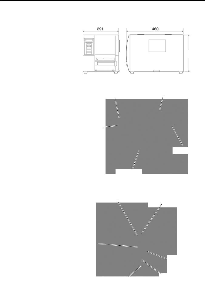
1.5.1 |
Dimensions |
|
|
|
|
|
|
291 (11.5) |
|||||||
|
460 (18.1) |
|
|||||
308
(12.1)
Dimensions in mm (inches)
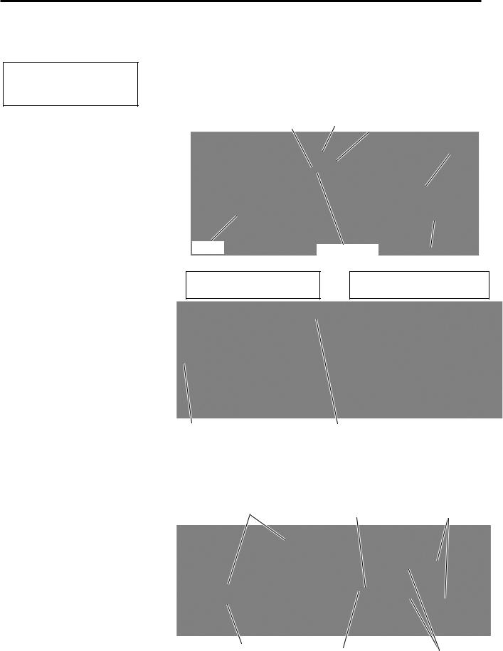
1.5.2 Front View |
LCD Message Display |
Top Cover |
Operation Panel
Supply Window
Media Outlet
1.5.3 Rear View
Parallel Interface
Connector (Centronics)
Serial Interface
Connector (RS-232C)
AC Power Inlet
PCMCIA Card Slot (Option), USB Connector (Option), or LAN Connector (Option)
USB Connector  (Option), Wireless
LAN Board (Option), or LAN Connector (Option)
Expansion I/O Interface Connector (Option)
Power Switch {: OFF
|: ON
E1- 3
1. PRODUCT OVERVIEW
ENGLISH VERSION EO1-33058
1.5 Appearance
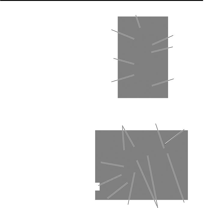
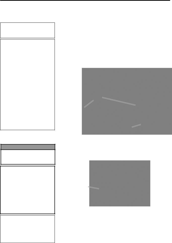
1.5.4 Operation Panel |
LCD Message Display |
POWER LED
(Green) ON LINE LED (Green)
ERROR LED (Red)
[FEED] key
[PAUSE] key
[RESTART] key
Please see Section 3.1 for further information about the Operation Panel.
1.5.5 Interior |
Ribbon Stopper Locking Ring |
Supply Holder
Print Head Block
Print Head
Platen
Head Lever |
Supply Shaft |
|
Ribbon Shaft |
E1- 4

1. PRODUCT OVERVIEW
ENGLISH VERSION EO1-33058
1.6 Options
1.6 Options
Option Name |
Type |
Description |
Swing cutter module |
B-4205-QM-R |
A stop and cut swing cutter. |
Rotary cutter module |
B-8204-QM-R |
Rotary cutter |
Strip module |
B-9904-H-QM-R |
This allows use of on-demand (peel-off) operation or to take-up |
|
|
labels and backing paper together when using the rewind guide |
|
|
plate. To purchase the strip module, please inquire at your local |
|
|
distributor. |
Ribbon saving module |
B-9904-R2-QM-R |
This module moves the print head up and down by using a |
|
|
solenoid to minimise ribbon usage as far as possible. |
Expansion I/O |
B-7704-IO-QM-R |
Installing this board in the printer allows connection to an external |
interface board |
|
device with the exclusive interface. |
PCMCIA interface |
B-9700-PCM-QM-R |
This board enables the use of the following PCMCIA cards. |
board |
|
ATA card: Conforming to PC card ATA standard |
|
|
Flash memory card: 1MB and 4MB cards (See Section 2.8.) |
Built-in LAN interface |
B-9700-LAN-QM-R |
This board enables the printer to be used in a LAN network. |
board |
|
|
USB interface board |
B-9700-USB-QM-R |
Installing this board enables a connection to a PC which has a USB |
|
|
interface. |
RFID module |
B-9704-RFID-U1-US-R |
Installing this module enables read and write of RFID tags. |
|
B-9704-RFID-U1-EU-R |
Applicable frequency range differs depending on the module types: |
|
B-9704-RFID-H1-QM-R |
U1-US: UHF, 902MHz to 928MHz |
|
|
U1-EU: UHF, 869.5MHz |
|
|
H1-QM: HF, 13.56MHz |
Fanfold paper guide |
B-4905-FF-QM-R |
This is a paper guide exclusively used for fanfold paper. |
module |
|
|
Wireless LAN board |
B-9700-WLAN-QM-R |
Installing this PC board allows a communication by wireless LAN. |
NOTE:
To purchase the optional kits, please contact the nearest authorised TOSHIBA TEC representative or TOSHIBA TEC Head Quarters.
E1- 5

2. PRINTER SETUP
ENGLISH VERSION EO1-33058
2. PRINTER SETUP
2. PRINTER SETUP
This section outlines the procedures to setup your printer prior to its operation. The section includes precautions, loading media and ribbon, connecting cables, setting the operating environment of the printer, and performing an online print test.
Setup Flow
Installation
Fitting the fan filter
Connecting the power cord
Loading the media
Media sensor position alignment
Loading the ribbon
Connecting to a host computer
Turning the power ON
Setting the operating environment
Installing the printer driver
Print test
Position and Print Tone Fine
adjustment
Automatic threshold setting
Manual threshold setting
Procedure
After referring to the Safety Precautions in this manual, install the printer on a safe and stable location.
Fit the supplied fan filter to the ventilation of the printer.
Connect a power cord to the power inlet of the printer, then, to an AC outlet.
Load a label stock or tag stock.
Adjust the position of feed gap sensor or black mark sensor according to the media to be used.
In case of thermal transfer printing, load the ribbon.
Connect the printer to a host computer or a network.
Turn on the printer power.
Set the printer parameters in the system mode.
If necessary, install the printer driver in your host computer.
Make a print test in your operating environment and check the print result.
If necessary, fine adjust the print start position, cut/strip position, print tone, etc.
If the print start position cannot be detected properly when pre-printed label is used, set the threshold automatically.
If the print start position cannot be detected properly even an automatic threshold setting is performing, manually set the threshold.
Reference
2.1Installation
2.2Fitting the Fan Filter
2.3Connecting the Power Cord
2.4Loading the Media
2.4Loading the Media
2.5Loading the Ribbon
2.6Connecting the Cables to Your Printer
2.7Turning the Printer ON/OFF
2.9Setting an Operating Environment
2.10Installing the Printer Drivers
2.11Print Test
2.12Position and Print Tone Fine Adjustment
2.13Threshold Setting
2.13Threshold Setting
E2- 1

2. PRINTER SETUP
ENGLISH VERSION EO1-33058
2.1 Installation
2.1 Installation
To insure the best operating environment, and to assure the safety of the operator and the equipment, please observe the following precautions.
•Operate the printer on a stable, level, operating surface in a location free from excessive humidity, high temperature, dust, vibration or direct sunlight.
•Keep your work environment static free. Static discharge can cause damage to delicate internal components.
•Make sure that the printer is connected to a clean source of AC Power and that no other high voltage devices that may cause line noise interference are connected to the same mains.
•Assure that the printer is connected to the AC mains with a threeprong power cable that has the proper ground (earth) connection.
•Do not operate the printer with the cover open. Be careful not to allow fingers or articles of clothing to get caught into any of the moving parts of the printer especially the optional cutter mechanism.
•Make sure to turn off the printer power and to remove the power cord from the printer whenever working on the inside of the printer such as changing the ribbon or loading the media, or when cleaning the printer.
•For best results, and longer printer life, use only TOSHIBA TEC recommended media and ribbons.
•Store the media and ribbons in accordance with their specifications.
•This printer mechanism contains high voltage components; therefore you should never remove any of the covers of the machine as you may receive an electrical shock. Additionally, the printer contains many delicate components that may be damaged if accessed by unauthorised personnel.
•Clean the outside of the printer with a clean dry cloth or a clean cloth slightly dampened with a mild detergent solution.
•Use caution when cleaning the thermal print head as it may become very hot while printing. Wait until it has had time to cool before cleaning. Use only the TOSHIBA TEC recommended print head cleaner to clean the print head.
•Do not turn off the printer power or remove the power plug while the printer is printing or while the ON LINE lamp is blinking.
E2- 2
2. PRINTER SETUP
ENGLISH VERSION EO1-33058
2.2 Fitting the Fan Filter
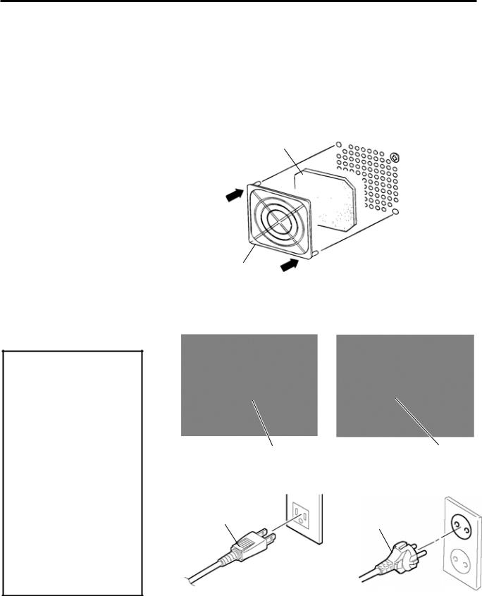
2.2 Fitting the Fan Filter |
When installing the printer, it is important to ensure that the Fan Filter is |
|
|
attached before using the printer. |
|
|
The Fan Filter consists of 2 parts: |
|
|
(1) |
Filter Pad |
|
(2) |
Filter Retainer |
To fit the Fan Filter, put the Filter Pad inside the Filter Retainer and simply press into place as shown in the diagram below, ensuring connecting pins are aligned with the connecting holes.
Filter Pad
Snap On
Filter Retainer
Snap On
2.3Connecting the Power Cord
CAUTION!
1.As a Power Cord is not supplied with the printer, please purchase an approved on that meets the safety standard of each country. (Refer to
APPENDIX 3.)
2.Make sure that the printer Power Switch is turned to the OFF position ({) before connecting the Power Cord to prevent possible electric shock or damage to the printer.
3.Connect the Power Cord to a supply outlet with a properly grounded (earthed) connection.
1.Make sure that the printer Power Switch is in the OFF ({) position. Connect the Power Cord to the printer as shown in the figure below
Power Switch |
Power Cord |
2.Plug the other end of the Power Cord into a grounded outlet as shown in the figure below.
Power Cord |
Power Cord |
|
[Example of US Type] |
[Example of EU Type] |
E2- 3
2. PRINTER SETUP
ENGLISH VERSION EO1-33058
2.4 Loading the Media
2.4 Loading the Media
WARNING!
1.Do not touch any moving parts. To reduce the risk of fingers, jewellery, clothing, etc., being drawn into the moving parts, be sure to load the media once the printer has stopped moving completely.
2.The Print Head becomes hot immediately after printing. Allow it to cool before loading the media.
3.To avoid injury, be careful not to trap your fingers while opening or closing the cover.
CAUTION!
Be careful not to touch the Print Head Element when raising the Print Head Block. Failure to do this may cause missing dots by static electricity or other print quality problems.
NOTES:
1.When the Head Lever is turned to Free position, the Print Head is raised.
2.To allow printing the Head Lever must be set to Lock position. (This ensures that the Print Head is closed.) There are two head pressure levels in the Lock position. Set the Head Lever depending on the media type:
Position c: Labels Position d: Tags
However, proper position may differ depending on media. For details, refer to TOSHIBA TEC authorised service representative.
3.Do not turn the Locking Ring counter-clockwise too far or it may come off the Supply Holder.
The following procedure shows the steps to properly load the media into the printer so that it feeds straight and true through the printer.
The printer prints both labels and tags.
1. Turn off the power and open the Top Cover.
2. Turn the Head Lever to Free position, then release the Ribbon Shaft Holder Plate.
3. Open the Print Head Block.
Print Head Block
c
d
Ribbon Shaft
Holder Plate
CAUTION!
When loading or replacing the media or a ribbon, be careful not to damage the print head with a hard object like a watch or a ring.
Care must be taken not to allow |
|
Care must be taken not to allow |
the metal or glass part of a watch |
|
a metal object like a ring to touch |
to touch the print head edge. |
|
the print head edge. |
Since the print head element can be easily damaged by shock, please treat it carefully by not hitting a hard object against it.
4.Turn the Locking Ring counterclockwise and remove the Supply Holder from the Supply Shaft.
Locking Ring
Supply Shaft
Supply Holder
E2- 4
2. PRINTER SETUP
ENGLISH VERSION EO1-33058
2.4 Loading the Media
2.4Loading the Media (Cont.)
NOTE:
Do not over-tighten the Locking Ring of the Supply Holder.
5.Put the media on the Supply Shaft.
6.Pass the media around the Damper, then pull the media towards the front of the printer.
7.Align the projection of the Supply Holder with the groove of the Supply Shaft, and push the Supply Holder against the media until the media is held firmly in place. This will centre the media automatically.
Then turn the Locking Ring clockwise to secure the Supply Holder.
Groove Damper
Supply Holder
Projection
Media |
Supply Shaft |
Locking Ring |
|
In case of a label rolled with the print side facing inside.
In case of a label rolled with the print side facing outside.
Media |
Damper |
8.Place the media between the Media Guides, adjust the Media Guides to the media width, and tighten the Locking Screw.
9.Check that the media path through the printer is straight. The media should be centred under the Print Head.
Media Guide |
Print Head |
Supply Holder |
Locking Screw |
Media |
Media Guide |
|
E2- 5

2. PRINTER SETUP
ENGLISH VERSION EO1-33058
2.4 Loading the Media
2.4Loading the Media (Cont.)
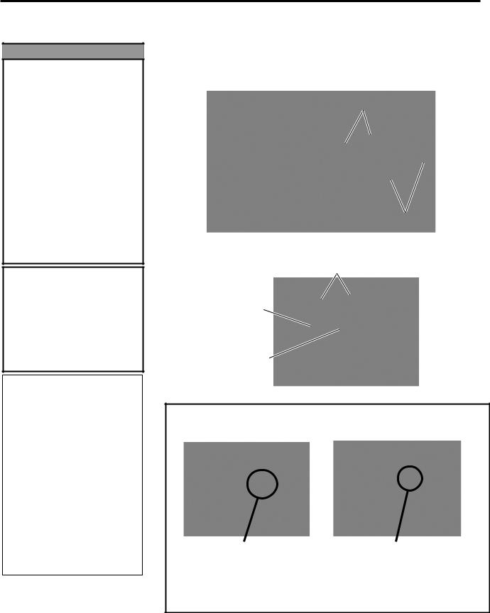
10.Lower the Print Head Block until it stops.
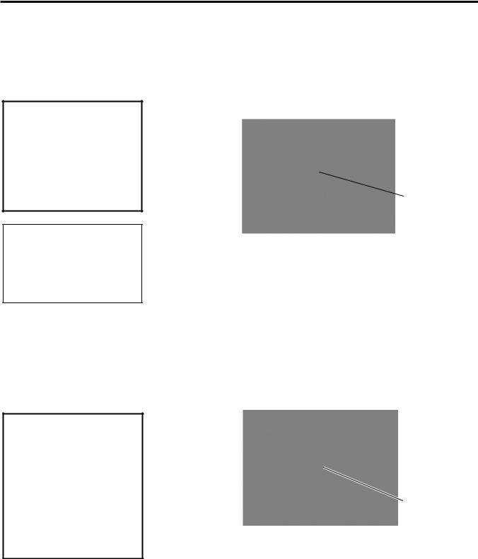
11.After loading the media, it may be necessary to set the Media Sensors used to detect the print start position for label or tag printing.
Setting the Feed Gap Sensor position
(1)Remove the Locking Screw that secures the Media Sensor.
(2)Manually move the Media Sensor so that the Feed Gap Sensor is
positioned at the centre of the labels. ( indicates the position of the Feed Gap Sensor).
(3)Tighten the Locking Screw.
Gap
NOTE:
Be sure to set the black mark sensor to detect the centre of the black mark, otherwise a paper jam or no paper error may occur.
Label |
Media Sensor |
Locking Screw |
Feed Gap Sensor |
|
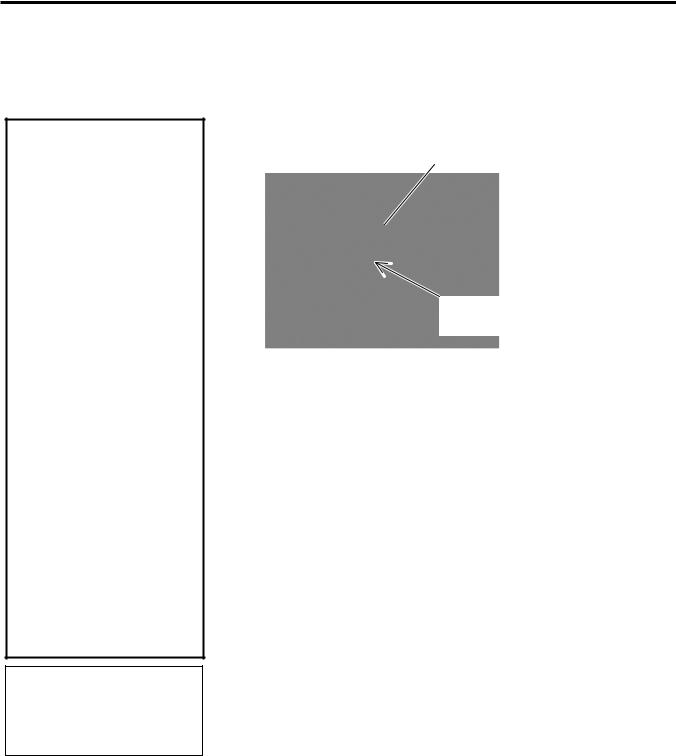
Setting the Black Mark Sensor position |
|
|
(1) |
Remove the Locking Screw that secures the Media Sensor. |
|
(2) |
Pull about 500 mm of media out of the front of the printer, turn the |
|
|
media back on itself and feed it under the Print Head past the sensor |
|
|
so that the black mark can be seen from above. |
|
(3) |
Manually move the Media Sensor so that the Black Mark Sensor is |
|
|
in line with the centre of the black mark on the media. ( indicates |
|
|
the position of the Black Mark Sensor). |
|
(4) |
Tighten the Locking Screw. |
Black Mark Sensor |
Media Sensor |
Locking Screw |
E2- 6
2. PRINTER SETUP
ENGLISH VERSION EO1-33058
2.4 Loading the Media
2.4Loading the Media (Cont.)
12.There are four issue modes available on this printer. How to set the media for each mode is provided below.
Batch mode
In the batch mode, the media is continuously printed and fed until the number of labels/tags specified in the issue command have been printed.
NOTES:
1.Be sure to set the Selection Switch to STANDARD/ PEEL OFF position.
2.The backing paper is easier to feed back to the Take-Up Spool if the Front Plate is removed.
3.Fit the Take-Up Clip so that the longer side of the clip is fitted into the shallow groove in the Take-Up Spool.
4.The backing paper can be wound directly onto the Takeup Spool or a paper core. When using the Take-up Spool, detach the Holder Stopper by removing the B- 3x4 screw. Otherwise, it may be difficult to pull out the wound backing paper roll.
Holder Stopper
B-3x4 Screw
Take-up Spool
Take-up Clip
When using a paper core, put the core on the Take-up Spool with the Holder Stopper on it, and attach the top edge of the backing paper to the core with adhesive tape. The Take-up Clip is not necessary.
This winding method is applicable to the Built-in Rewinder mode.
Strip mode (Option)
When the optional Strip Module is fitted, the backing paper is automatically removed from the label at the Strip Plate as each label is printed.
(1)Remove enough labels from the leading edge of the media to leave 500mm of backing paper free.
(2)Insert the backing paper under the Strip Plate.
(3)Wind the backing paper onto the Take-up Spool and fix it in position with the Take-up Clip. (Wind the paper counterclockwise around the spool as this is the direction it rotates.)
(4)Rotate the Take-up Spool anti-clockwise a few times to remove any slack in the backing paper.
(5)Set the Selection Switch mounted on the Rewinder Assembly to
STANDARD/PEEL OFF position.
Take-up Spool
Front Plate
Take-up Clip
Black Screw Strip Plate Backing Paper
E2- 7
2. PRINTER SETUP
ENGLISH VERSION EO1-33058
2.4 Loading the Media
2.4Loading the Media (Cont.)
NOTE:
Be sure to set the Selection Switch to REWINDER position.
ADJUSTMENT:
If the media skews when using the Built-in Rewinder, turn the Adjustment Knob of the Rewinder Guide Plate to correct the media feed. Clockwise turn moves the Rewinder Guide Plate forward and counter-clockwise moves it backward.
When the media skews to the right: Loosen the SM-4x8 screw, turn the Adjustment Knob clockwise, and then tighten the SM-4x8 screw when the Rewinder Guide Plate is positioned correctly.
When the media skews to the left: Loosen the SM-4x8 screw, turn the Adjustment Knob counter-clockwise, and tighten the SM-4x8 screw when the Rewinder Guide Plate is positioned correctly.
WARNING!
The cutter is sharp, so care must be taken not to injure yourself when handling the cutter.
CAUTION!
1.Be sure to cut the backing paper of the label. Cutting labels will cause the glue to stick to the cutter which may affect the cutter quality and shorten the cutter life.
2.Use of tag paper when the thickness exceeds the specified value may affect the cutter life.
NOTE:
When using the Rotary Cutter, be sure to install the Ribbon Saving Module (B-9904-R2-QM-R).
Failure to do this may cause a paper jam or ribbon error.
Built-in rewinder mode (Option)
The Rewinder Assembly of the Strip Module can be used in batch mode to take up the printed media as a Built-in Rewinder.
(1)Remove the two Black Screws to detach the Front Plate.
(2)Attach the Rewinder Guide Plate enclosed with the optional Strip Module to the Strip Plate with the SMW-4x8 sems screws.
(3)Insert the media under the Rewinder Guide Plate.
(4)Wind the media onto the Take-up Spool and fix it in position with the Take-up Clip.
(5)Rotate the Take-up Spool counterclockwise a few times to remove any slack in the media.
(6)Set the Selection Switch mounted on the Rewinder Assembly to REWINDER position.
SMW-4x8 Screw
Rewinder
Guide Plate
 Adjustment Knob
SM-4x8 Screw
Cut mode (Option)
When the optional Cutter Module is fitted, the media is automatically cut. A swing cutter and a rotary cutter are available as an option, but they are used in the same way.
Insert the leading edge of the media into the Media Outlet of the Cutter Module.
Cutter Module
Media 
Media Outlet 
13.If the loaded media is direct thermal media (a chemically treated
surface), the media loading procedure is now completed. Close the Ribbon Shaft Holder Plate, and turn the Head Lever to Lock position to close. Then, close the Top Cover.
If the media is thermal transfer media, it is also necessary to load a ribbon. Refer to Section 2.5 Loading the Ribbon.
E2- 8
2. PRINTER SETUP
ENGLISH VERSION EO1-33058
2.5 Loading the Ribbon
2.5 Loading the Ribbon
WARNING!
1.Do not touch any moving parts. To reduce the risk of fingers, jewellery, clothing, etc., being drawn into the moving parts, be sure to load the ribbon once the printer has stopped moving completely.
2.The print head becomes hot immediately after printing. Allow it to cool before loading the ribbon.
3.To avoid injury, be careful not to trap your fingers while opening or closing the cover.
CAUTION!
Be careful not touch the Print Head Element when raising the Print Head Block. Failure to do this may cause missing dots by static electricity or other print quality problems.
NOTES:
1.When attaching the ribbon stoppers, make sure that the pinchers face into the printer
2.Be sure to remove any slack in the ribbon when printing. Printing with a wrinkled ribbon will lower the print quality.
3.The Ribbon Sensor is mounted on the rear of the Print Head Block to detect a ribbon end. When a ribbon end is detected, “NO RIBBON” message will appear on the display and the ERROR LED will illuminate.
There are two types of media available for printing on: these are thermal transfer media and direct thermal media (a chemically treated surface). DO NOT LOAD a ribbon when using a direct thermal media.
1.Grasp the tabs on the top and bottom of the Ribbon Stoppers and move the Ribbon Stoppers back to the end of the Ribbon Shaft.
Ribbon Stopper
Ribbon Shaft
2.Leaving plenty of slack between the ribbon spools, place the ribbon onto the Ribbon Shafts as shown below.
Ribbon Shaft
Print Head Block
Ribbon Take-up Roll
CAUTION!
When loading or replacing the media or a ribbon, be careful not to damage the print head with a hard object like a watch or a ring.
Care must be taken not to allow |
|
Care must be taken not to allow |
the metal or glass part of a watch |
|
a metal object like a ring to touch |
to touch the print head edge. |
|
the print head edge. |
Since the print head element can be easily damaged by shock, please treat it carefully by not hitting a hard object against it.
E2- 9

2. PRINTER SETUP
ENGLISH VERSION EO1-33058
2.5 Loading the Ribbon
2.5Loading the Ribbon (Cont.)
3.Slide the Ribbon Stoppers along the Ribbon Shafts to a position where the ribbon is centred when fitted.
4.Lower the Print Head Block and set the Ribbon Shaft Holder Plate aligning its holes with the Ribbon Shafts.
5.Take up any slack in the ribbon. Wind the leading tape onto the ribbon take-up roll until the ink ribbon can be seen from the front of the printer.
NOTE:
Ribbon loss per ribbon saving varies according to the relation between the outer roll diameter of the used ribbon and the print speed.
Print speed |
Ribbon loss/Ribbon saving |
3”/sec. |
Approx. 6 mm |
6”/sec. |
Approx. 10 mm |
10”/sec. |
Approx. 20 mm |
 Ribbon Shaft
Holder Plate
6.Turn the Head Lever to Lock position to close the Print Head.
7.Close the Top Cover.
Auto Ribbon Saving Mode
When the auto ribbon saving function is selected, it will be activated to reduce ribbon loss when a no print area extends more than 20 mm (3 or 6 ips) or 30 mm (10 ips). For further information on this function, please ask a TOSHIBA TEC authorised service representative.
E2-10
2. PRINTER SETUP
ENGLISH VERSION EO1-33058
2.6 Connecting the Cables to Your Printer
2.6Connecting the Cables to Your Printer
NOTES:
1.The picture on the right shows the layout of the interface connectors when the options are fully installed. It may be different depending on your system configuration.
2.The USB interface and LAN interface cannot be used at the same time.
The following paragraphs outline how to connect the cables from the printer to your host computer, and will also show how to make cable connections to other devices. Depending on the application software you use to print labels, there are 4 possibilities for connecting the printer to your host computer. These are:
•A serial cable connection between the printer’s RS-232 serial connector and one of your host computer’s COM ports. (Refer to APPENDIX 2.)
•A parallel cable connection between the printer’s standard parallel connector and your host computer’s parallel port (LPT).
•An Ethernet connection using the optional LAN board.
•A USB cable connection between the printer’s optional USB connector and your host computer’s USB port. (Conforming to USB 1.1)
The diagram below shows all the possible cable connections to the current version of the printer.
, , or
, , or 8
Parallel Interface Connector (Centronics)
Serial Interface Connector (RS-232C)
Expansion I/O Interface Connector (Option)
Power Inlet
USB Interface Connector (Option)
PCMCIA Card Slot (Option)
LAN Interface Connector (Option)
8 Wireless LAN Board (Option)
E2-11
2. PRINTER SETUP
ENGLISH VERSION EO1-33058
2.7 Turning the Printer ON/OFF
2.7Turning the Printer ON/OFF
2.7.1 Turning ON the Printer
CAUTION!
Use the power switch to turn the printer On/Off. Plugging or unplugging the Power Cord to turn the printer On/Off may cause fire, an electric shock, or damage to the printer.
When the printer is connected to your host computer it is good practice to turn the printer ON before turning on your host computer and turn OFF your host computer before turning off the printer.
1.To turn ON the printer power, press the Power Switch as shown in the diagram below. Note that ( | ) is the power ON side of the switch.
 Power Switch
NOTE:
If a message other than ON LINE appears on the display or the ERROR LED lamp is illuminated, go to Section 5.1,
Error Messages.
2.Check that the ON LINE message appears in the LCD Message Display and that the ON LINE and POWER LED lights are illuminated.
2.7.2 Turning OFF the Printer 1. Before turning off the printer Power Switch verify that the ON LINE message appears in the LCD Message Display and that the ON LINE LED light is on and is not flashing.
CAUTION!
1.Do not turn off the printer power while the media is being printed as this may cause a paper jam or damage to the printer.
2.Do not turn off the printer power while the ON LINE lamp is blinking as this may cause damage to your computer.
2. To turn OFF the printer power press the Power Switch as shown in the diagram below. Note that ( ) is the power OFF side of the switch.
Power Switch
E2-12
2. PRINTER SETUP
ENGLISH VERSION EO1-33058
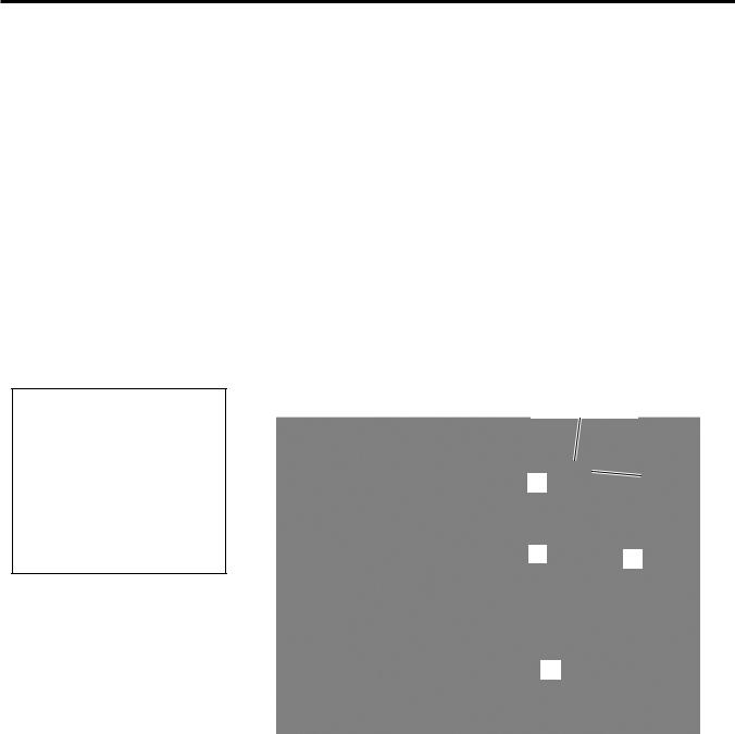
2.8 Inserting the Optional PCMCIA Cards
2.8 Inserting the Optional When the optional PCMCIA Interface Board is installed into the printer, PCMCIA Cards there will be a PCMCIA slot available as shown in the figure below.
This allows the use of a Flash Memory type card. The following paragraphs outline how to insert PCMCIA cards.
CAUTION!
1.To protect PC cards, discharge static electricity from your body by touching the metal cabinet of the printer before touching the card.
2.Before inserting or removing a PCMCIA card make sure that the printer’s power is turned off.
3.Be sure to protect PCMCIA Cards when not in use by putting them into their protective covers.
4.Do not subject the card to any shocks or excessive force nor expose the card to extremes in temperature or humidity.
5.The card may be inserted into the slot halfway even in the wrong orientation. However, the slot is safety designed so that the card will not seat against the connector pins.
NOTE:
Reading a read-only-type flash memory is possible if it has been used on the TOSHIBA printer, such as B-472 and B-572.
1.Make sure that the printer’s Power Switch is in the OFF position.
2.Hold the PCMCIA Card so that the side with the model name faces
right.
Eject Button
Model
Name
3. The following PCMCIA cards or equivalent can be used.
Type |
Maker |
Description |
Remarks |
||||||
ATA Card |
San Disk, |
A card conforming to the |
---------- |
||||||
Hitachi |
PC card ATA standard |
||||||||
|
|
||||||||
|
Maxell |
EF-4M-TB |
|
|
|
|
|
|
|
|
|
CC |
|
|
|
||||
|
|
|
|
|
|
|
|
|
|
|
Maxell |
EF-4M-TB |
DC |
|
|
Read/Write |
|||
|
|
|
|
|
|||||
|
Centennial |
FL04M-15-11119-03 |
|||||||
|
|
||||||||
|
Technologies INC. |
|
|||||||
|
|
|
|
|
|
|
|
||
|
INTEL |
IMC004FLSA |
|
||||||
Flash Memory |
Simple |
STI-FL/4A |
|
||||||
TECNOLOGY |
|
||||||||
|
|
|
|
|
|
|
|||
Card (4 MB) |
Mitsubishi |
MF84M1-G7DAT01 |
|
||||||
|
PC Card KING |
FJN-004M6C |
|
||||||
|
MAX |
|
|||||||
|
|
|
|
|
|
|
Read (See NOTE.) |
||
|
Centennial |
FL04M-20-11138-67 |
|||||||
|
Technologies Inc. |
|
|||||||
|
|
|
|
|
|
|
|
||
|
PC Card |
FJP-004M6R |
|
||||||
|
Mitsubishi |
MF84M1-GMCAV01 |
|
||||||
Flash Memory |
Maxell |
EF-1M-TB |
|
|
|
||||
AA |
|
|
|||||||
Card (1 MB) |
Mitsubishi |
MF81M1-GBDAT01 |
|
||||||
E2-13
2. PRINTER SETUP
ENGLISH VERSION EO1-33058
2.9 Setting an Operating Environment
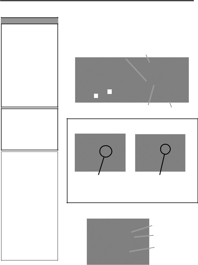
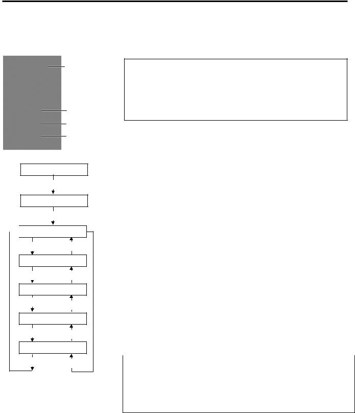
2.9Setting an Operating Environment
LCD Message
Display
FEED key
RESTART key
PAUSE key
ON LINE
[PAUSE]
PAUSE
Hold down [RESTART] for 3 sec.

 <1>RESET
[FEED] [RESTART]
<2>PARAMETER SET
[FEED] [RESTART]
<3>ADJUST SET
[FEED] [RESTART]
<4>DUMP MODE
[FEED] [RESTART]
<5>EXPAND MODE
[FEED] [RESTART]
Depending on the settings of your host computer or an interface to be used, it may be necessary to change the printer parameter settings.
Follow the procedures described below to change the printer parameter settings in the System Mode to correspond to your environment.
NOTE:
Incorrect settings can cause the printer to function erroneously. If you have any problems with the parameter settings, please contact your nearest TOSHIBA TEC service representative.
For the settings this manual does not cover, please contact your nearest TOSHIBA TEC service representative, or refer to the B-SX4T/SX5T Series Key Operation Specification stored in the CD-ROM.
How to enter the System Mode
1.Turn on the printer and confirm that “ONLINE” appears on the LCD Message Display.
2.Press the [PAUSE] key to pause the printer.
3.Hold down the [RESTART] key for three seconds until “<1>RESET” is displayed.
The System Mode consists of the following menus.
<1>RESET |
This menu is used to clear print data sent from a |
|
PC and return the printer to an idle state. |
|
Refer to Section 3.3 Reset. |
<2>PARAMETER SET |
This menu is used to set the printer parameters. |
|
Refer to Section 2.9.1 Parameter Setting. |
<3>ADJUST SET |
This menu is used to make a fine adjustment of a |
|
print start position, cut position, etc. |
|
Refer to Section 2.12 Position and Print Tone |
|
Fine Adjustment. |
<4>DUMP MODE |
This menu is used to print the data in the receive |
|
buffer for debug. |
|
Refer to Section 2.9.2 Dump Mode Setting. |
<5>EXPAND MODE |
This menu is used to start the program for |
|
BASIC mode. |
|
Refer to Section 2.9.3 BASIC Expansion |
|
Mode. |
|
NOTES: |
1.System Mode menus can be selected with the [RESTART] or [FEED] key.
2.To enter each of the above System Mode menus, press the [PAUSE] key when the menu is displayed.
3.If the [PAUSE] key is pressed with “<1>RESET” being displayed, the printer will turn to an idle state and the message will change to “ONLINE”.
E2-14

2. PRINTER SETUP
ENGLISH VERSION EO1-33058
2.9 Setting an Operating Environment
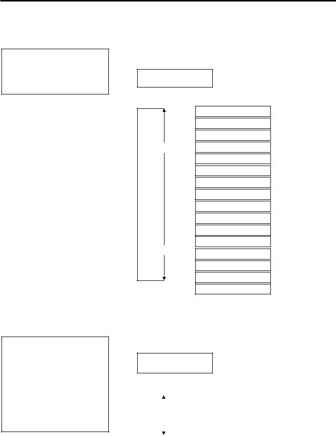
2.9.1 Parameter Setting |
While “<2>PARAMETER SET” is displayed on the LCD Message |
|
Display, press the [PAUSE] key to enter the Parameter Setting Mode. |
|
The Parameter Setting Mode contains the following sub menus. Each |
|
time the [PAUSE] key is pressed, the sub menus are displayed |
|
sequentially. |
(1) Character code selection
(2) Character zero selection
(3) Baud rate selection
(4) Data length selection
(5) Stop bit selection
(6) Parity selection
(7) Flow control code selection
(8) LCD language selection
(9) Auto forward wait selection
(10) Head up cut/Rewinder selection
(11) Solenoid type selection
(12) Ribbon saving function selection
(13) Control code selection
(14) Strip wait status selection
(15) FEED key function selection
(16) KANJI code selection
(17) EURO code selection
(18) Auto print head check selection
(19) Centronics ACK/BUSY timing selection
(20) Web printer function selection
(21) Input prime selection
(22) Ribbon near end selection
(23) Expansion I/O interface selection
(24) Centronics interface selection
(25) Plug & Play selection
(26) Label end/ribbon end selection
(27) Pre-strip selection
(28) Reverse feed speed selection
(29) Maxi code specification selection
(30) Print head type selection
(31) System mode password setting
E2-15
2. PRINTER SETUP
ENGLISH VERSION EO1-33058
2.9 Setting an Operating Environment
2.9.1Parameter Setting (Cont.)
NOTE:
Be careful if the printer is turned off without pressing the [PAUSE] key, the selected value does not become effective.
(1) Character Code Selection
This parameter is to choose a character code used for printing. Printed characters differ depending on a chosen character code and font. For details of characters, refer to the B-SX4T/SX5T Series External
Equipment Interface Specification (Printer Command Manual). When “<2>PARAMETER SET” appears, press the [PAUSE] key.
<2>PARAMETER SET FONT CODE PC-850
Use the [FEED] or [RESTART] key to select a desired option.
FONT CODE PC-850
FONT CODE PC-852
FONT CODE PC-857
[RESTART] FONT CODE PC-8
FONT CODE PC-851
FONT CODE PC-855
FONT CODE PC1250
FONT CODE PC1251
FONT CODE PC1252
FONT CODE PC1253
FONT CODE PC1254
FONT CODE PC1257
[FEED]
FONT CODE LATIN9
FONT CODE Arabic
FONT CODE PC-866
FONT CODE UTF-8
NOTE:
The following fonts do not support a zero with slash.
Bit Map Font:
OCR-A, OCR-B, GOTHIC 725 Black, Kanji, Chinese
Outline Font:
Price Font 1, Price Font 2, Price Font 3, DUTCH 801 Bold, BRUSH 738 Regular, GOTHIC 725 Black, True Type Font
After selecting a character code, press the [PAUSE] key.
(2) Character Zero Selection
This parameter is to choose the way to indicate zero between “0” and “Ø”. When “<2>PARAMETER SET” appears, press the [PAUSE] key twice.
<2>PARAMETER SET ZERO FONT 0
Use the [FEED] or [RESTART] key to select a desired option.
|
|
|
|
|
|
|
|
|
|
|
|
|
|
|
|
|
|
|
|
|
|
|
|
ZERO FONT |
0 |
(Without slash) |
|
[RESTART] |
|
||||||
|
|
|
|
|
|
|
|
|
|
|
[FEED] |
|
ZERO FONT |
Ø |
(With slash) |
||
|
|
|
|
|
|
|
|
|
|
|
|
|
|
|
|
|
|
|
|
|
|
|
|
|
|
|
After selecting a character zero, press the [PAUSE] key.
E2-16
Loading...