


400A
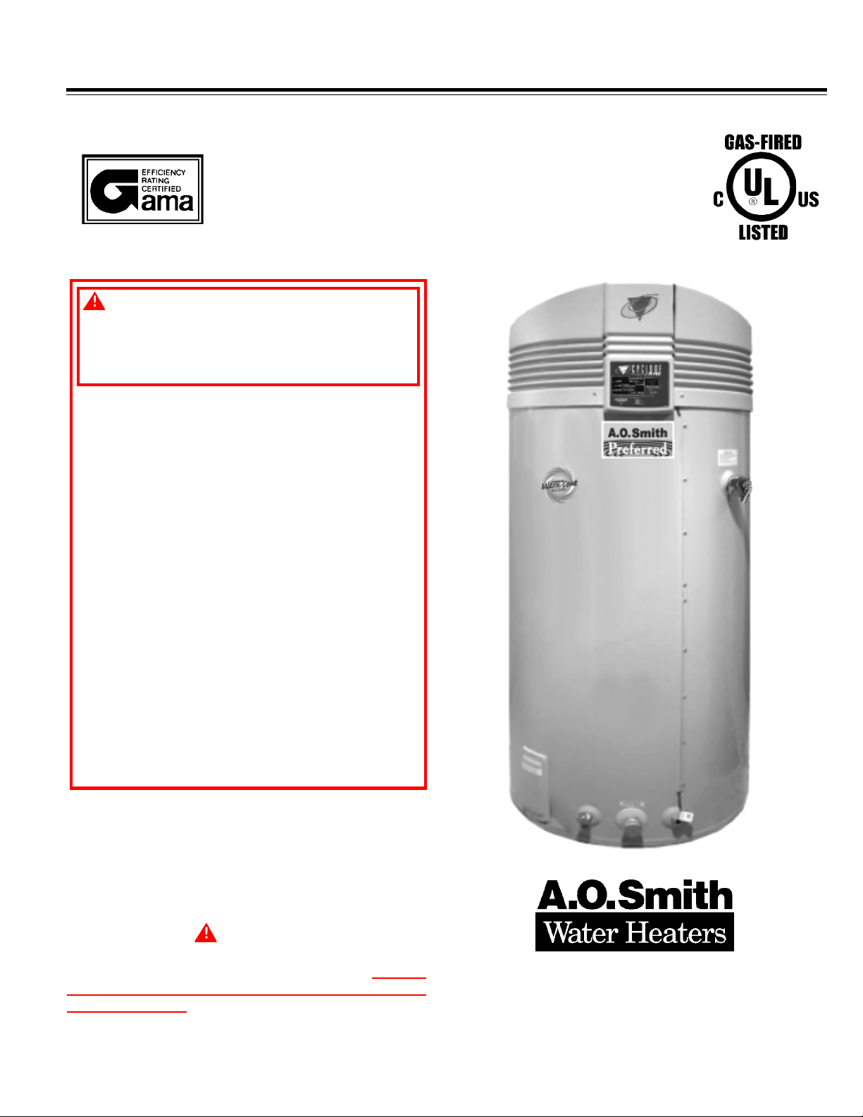
CYCLONE XHE®
Series 970
Series 970
Model BTH 300A AND 400A
COMMERCIAL GAS WA TER HEA TER
GAS-FIRED POWER BURNER
FOR DOMESTIC HOT W A TER
• INST ALLATION • OPERATION • SERVICE • MAINTENANCE • LIMITED WARRANTY
W ARNING: If the information in these
instructions is not followed exactly , a fire
or explosion may result causing property
damage, personal injury or death.
– Do not store or use gasoline or other
flammable vapors and liquids in the
vicinity of this or any other appliance.
– WHAT TO DO IF YOU SMELL GAS:
• Do not try to light any appliance.
• Do not touch any electrical switch;
do not use any phone in your
building.
• Immediately call your gas supplier
from a neighbor's phone. Follow the
gas supplier's instructions.
• If you cannot reach your gas supplier,
call the fire department.
– Installation and service must be
performed by a qualified installer,
service agency or the gas supplier.
Thank you for buying this energy efficient water heater from
A.O. Smith Water Products Company. We appreciate your
confidence in our products.
CAUTION
TEXT PRINTED OR OUTLINED IN RED CONTAINS
INFORMA TION RELATIVE TO YOUR SAFETY. PLEASE
READ THOROUGHLY BEFORE INSTALLING AND USING
THIS APPLIANCE.
PLACE THESE INSTRUCTIONS ADJACENT TO HEA TER AND NOTIFY OWNER TO KEEP FOR FUTURE REFERENCE.
PRINTED IN U.S.A. 0306 PART NO. 197373-000
1
A DIVISION OF A.O. SMITH CORPORATION
Mc BEE, SOUTH CAROLINA
STRATFORD (ONTARIO) CANADA
www.hotwater.com
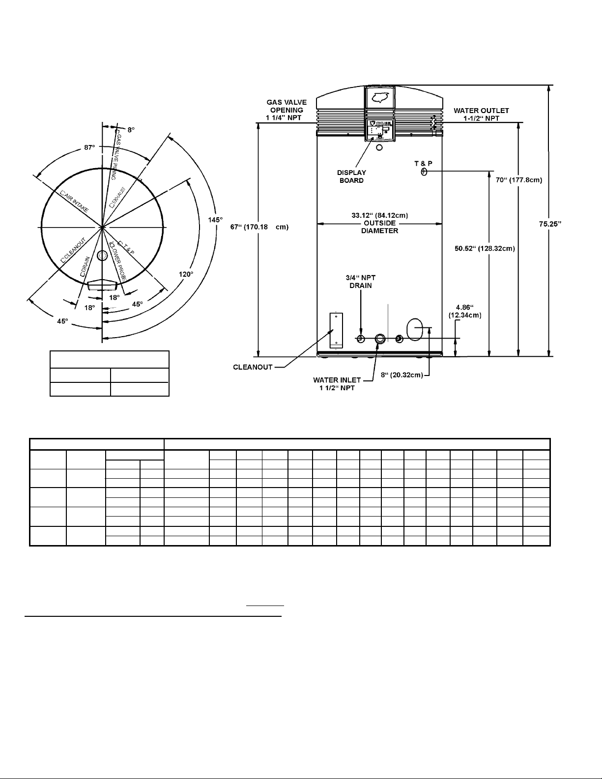
ROUGH-IN-DIMENSIONS
GAS VALVE PIPING
BT H-3 00 1 1/4" NPT
BT H -400 1 1/4" NPT
TABLE 1 RECOVER Y CAP ACITIES.
U.S. Gallons/Hr and Litres/Hr at TEMPERATURE RISE INDICATED
MODEL GAS BTUH KW Capacity C° 11C° 17C° 22C° 28C° 33C° 39C° 44C° 50C° 56C° 61C° 67C° 72C° 78C°
BTH-300
BTH-300
BTH-400
BTH-400
Recovery capacities are based on heater performance at 98% thermal efficiency .
TYPE OF INPUT Approx. F° 20F° 30F° 40F° 50F° 60F° 70F° 80F° 90F° 100F° 110° 120F° 130F° 140F°
NA TURAL
PROPAN E
NA TURAL
PROPAN E
300,000 130 US Gals. GPH 1782 1188 891 713 594 509 445 396 356 324 297 274 255
88 492 Litres LPH 6745 4496 3372 2698 2248 1927 1686 1499 1349 1226 1124 1038 964
280,000 130 US Gals. GPH 1663 1109 832 665 554 475 416 370 333 302 277 256 238
82 492 Litres LPH 6295 4197 3148 2518 2098 1799 1574 1399 1259 1145 1049 968 899
400,000 130 US Gals. GPH 2376 158 4 1188 950 792 679 594 528 475 432 396 366 339
117 492 Litres LPH 8993 5995 4496 3597 2998 2569 2248 1998 1799 1635 1499 1384 1285
400,000 130 US Gals. GPH 2376 1584 1188 950 792 679 594 528 475 432 396 366 339
117 492 Litres LPH 8993 5995 4496 3597 2998 2569 2248 1998 1799 1635 1499 1384 1285
FOREWORD
These designs comply with the current edition of the
American
National Standard for Gas Water Heaters, Volume III,
ANSI Z21.10.3 / CSA 4.3 as an automatic circulating tank water
heater, and automatic storage water heaters.
Detailed installation diagrams are found in this manual. These
diagrams will serve to provide the installer with a reference for the
materials and methods of piping necessary. It is highly essential
that all water, gas piping and wiring be installed as shown on the
diagrams.
Particular attention should be given to the installation of
thermometers at the locations indicated on the diagrams as these
are necessary for checking the proper functioning of the heater.
In addition to these instructions, the equipment shall be installed
in accordance with those installation regulations in force in the
local area where the installation is to be made. These shall be
carefully followed in all cases. Authorities having jurisdiction should
be consulted before installations are made.
In the absence of local codes, the installation must comply
with the current editions of the National Fuel Gas Code,
ANSI Z223.1/NFPA 54 and the National Electrical Code,
NFPA 70 or CAN/CSA-B149.1, the Natural Gas and Propane
Installation Code and CSA C22.1, the Canadian Electrical Code.
All documents are available from the Canadian Standards
Association, 8501 East Pleasant Valley Road, Cleveland, OH 44131.
NFPA documents are also available from the National Fire
Protection Association, 1 Batterymarch Park, Quincy, MA 02269.
2

TABLE OF CONTENTS
PAGE
ROUGH-IN DIMENSIONS ................................................................... 2
FOREWORD ...................................................................................... 2
FEATURES ........................................................................................ 3
Water Temperature Control.......................................................... 3-4
High Limit Switch (E.C.O.)............................................................ 4
Dishwashing Machine Requirement ............................................ 4
Circulating Pump........................................................................... 4
INSTALLA TION INSTRUCTIONS ........................................................ 4
Required Ability ............................................................................ 4
Insulation Blankets ....................................................................... 4-5
Locating The Heater..................................................................... 5
Clearances ................................................................................... 5
Hard Water ................................................................................... 5
Air Requirements ......................................................................... 6
Mechanical Exhausting of Room Air ............................................ 6
Unconfined Space ........................................................................ 6
Confined Space ............................................................................ 6
Chemical Vapor Corrosion........................................................... 6
VENTING ........................................................................................... 6
Vent Pipe Termination ................................................................... 6
Direct Venting............................................................................... 7-8
Direct Vent Terminal Installation ................................................... 8
Installation Sequence ................................................................... 8-9
Vertical Vent Terminal Installation ................................................ 9
Installation Sequence ................................................................... 9
Installation of Vent System .......................................................... 10
Vent Pipe Preparation................................................................... 10-11
CONTROLS AND SWITCHES ............................................................ 11
Blower Prover Switch ................................................................. 11
Blocked Outlet Prover Switch...................................................... 11
Blocked Inlet Prover Switch......................................................... 11
Low Gas Pressure Switch .......................................................... 11
On/Off Switch .............................................................................. 11
Hot Surface Igniter ....................................................................... 11
GAS PIPING....................................................................................... 12
Connection of Gas Pipe ............................................................... 12-13
Purging ......................................................................................... 13
Gas Meter Size - City Gases Only .............................................. 1 3
Gas Pressure Regulation............................................................. 13
Gas Valves................................................................................... 13
SYSTEM CONNECTIONS .................................................................. 13
Thermometers .............................................................................. 13
Relief Valve .................................................................................. 13
Water Line Connections .............................................................. 13
PAGE
Closed System ................................................................................ 13
Water (Potable) Heating & Space Heating ...................................... 13
Heater Wiring ..................................................................................14-15
OPERATION.......................................................................................... 15
Sequence of Operation .................................................................. 15
Self Diagnostic Controller ............................................................... 15
Gas Value LEDs Flashing ............................................................... 15
Error Codes ..................................................................................... 16
Fault Conditions............................................................................... 16
No Incoming Line Voltage................................................................ 16
No Low Voltage .......................................................................... 16
T emperature Probe Fault................................................................. 16
E.C.O. Switch Open ........................................................................ 17
Control Bad...................................................................................... 17
Combustion Air Blockage ................................................................ 17
PRIOR TO STA RT-UP ........................................................................... 18
Required Ability ............................................................................... 18
OPERATING INSTRUCTIONS................................................................ 18
Adjustment Procedure (Initial Start-Up) .......................................... 18
Lighting Instructions ........................................................................ 19
Cathodic Protection ......................................................................... 20
Precautions ..................................................................................... 20
GENERAL INFORMA TION .................................................................... 20
Power Burner ................................................................................. 20
High Limit ......................................................................................... 20
High Altitude Installations ................................................................ 20
MAINTENANCE .................................................................................... 20
General............................................................................................ 20
Maintenance Schedule ................................................................... 20
Flushing ........................................................................................... 21
Draining ........................................................................................... 21
Sediment Removal........................................................................... 21
Lime Scale Removal ........................................................................ 21
Powered Anode System .................................................................21-22
Drain Valve and Access Panels ..................................................... 22
Relief Valve ..................................................................................... 22
Internal Circulating Pump................................................................. 22
Vent System .................................................................................... 22
INSTALLA TION DIAGRAMS .................................................................23-27
Manifold Kits .................................................................................... 28
CHECKLIST AND SERVICE INFORMA TION .......................................... 29
TROUBLE-SHOOTING..........................................................................29-30
REPLACEMENT P ARTS ........................................................................ 30
LIMITED WARRANTY........................................................................... 31
FEATURES
IMPORTANT
IT IS REQUIRED THAT A QUALIFIED SERVICE TECHNICIAN
PERFORM THE INITIAL FIRING OF THE HEATER. AT THIS TIME
THE USER SHOULD NOT HESIT ATE TO ASK THE TECHNICIAN
ANY QUESTIONS WHICH HE MAY HAVE IN REGARD TO THE
OPERATION AND MAINTENANCE OF THE UNIT.
A CHECKLIST AND SERVICE INFORMATION section are included
at the rear of this manual. By using this checklist the user may be
able to make minor operational adjustments and save himself
unnecessary service calls. However, the user should not attempt
repairs which are not listed in this section.
WATER TEMPERATURE CONTROL
DANGER
THIS WATER HEATER IS EQUIPPED WITH AN ADJUSTABLE
THERMOSTAT TO CONTROL WATER TEMPERATURE. HOT
WATER TEMPERATURES REQUIRED FOR AUTOMATIC
DISHWASHER AND LAUNDRY USE CAN CAUSE SCALD BURNS
RESULTING IN SERIOUS PERSONAL INJURY AND/OR DEATH.
THE TEMPERA TURE A T WHICH INJUR Y OCCURS V ARIES WITH
THE PERSON’S AGE AND TIME OF EXPOSURE. THE SLOWER
RESPONSE TIME OF CHILDREN, AGED OR DISABLED
PERSONS INCREASES THE HAZARDS TO THEM. NEVER
ALLOW SMALL CHILDREN TO USE A HOT WATER TAP, OR TO
DRAW THEIR OWN BATH WATER. NEVER LEAVE A CHILD OR
DISABLED PERSON UNATTENDED IN A BATHTUB OR
SHOWER.
THE WATER HEATER SHOULD BE LOCATED IN AN AREA
WHERE THE GENERAL PUBLIC DOES NOT HAVE ACCESS TO
SET TEMPERATURES.
The water temperature is controlled using the Temperature Control
Button on the Display at the front of the unit (See Figure 1). This
control utilizes two temperature probes to determine the tank
temperature. The primary temperature probe is located at the top
of the tank and the other is near the water inlet.
3
“AT A GLANCE” BTH 300/400
QUICK INSTALLATION TIPS
Horizontal Sidewall V enting Vertical Rooftop Venting
4
The temperature may be adjusted from 80°F/27°C to 180°F/82°C.
The thermostat was adjusted to 120°F/49°C before the heater
was shipped from the factory. It is recommended that lower water
temperatures be used to avoid the risk of scalding. It is further
recommended, in all cases, that the water temperature be set for
the lowest temperature which satisfies your hot water needs.
This will also provide the most energy efficient operation of the
water heater and minimize scale formation.
WATER TEMPERATURE SETPOINT
ADJUSTMENT PROCEDURE
CAUTION
THE TEMPERATURE OF THE WA TER AT THE T ANK OUTLET MAY
NOT CORRESPOND TO THE TEMPERATURE SETPOINT
PROGRAMMED IN THE CONTROLLER. THE USER CAN EASIL Y
CHANGE THE TEMPERA TURE SETPOINT A T ANY TIME BY USING
THE FOLLOWING PROCEDURE. IN ALL CASES, INPUT POWER
MUST BE APPLIED TO THE CONTROLLER TO PERFORM ANY
PROGRAMMING OPERA TIONS.
To change or view the current programmed temperature setpoint
value, utilize the pushbutton on the Display Board. Momentarily
pressing the button will briefly illustrate the existing setpoint value.
If the button is held down for more than one second, the
programming mode is automatically entered and the setpoint value
will begin incrementing or decrementing by one degree per second.
The control will alternate between between the incrementing or
decrementing mode each time the button is pressed. When the
desired setpoint value is reached, simply release the button and
the controller will automatically retain this value in temporary
memory. After one complete heat cycle, the new setpoint is
transferred to permanent memory.
Note: If power is interrupted prior to completing one heat cycle, the
new setpoint will not be transferred to permanent memory.
Therefore, it is a good practice to recheck the setpoint value at the
end of a heat cycle after a new value has been entered.
If the button is held down long enough, the setpoint will reach 70°F
(the minimum value) and stop. At this point, if the desired setpoint
has not been obtained, release the button and depress it again.
The setpoint value will now restart at 70°F and once again increase
in value for as long as the button is pressed.
Figure 1 shows the approximate time-to-burn relationship for normal
adult skin. Short repeated heating cycles caused by small hot water
uses can cause temperatures at the point of use to exceed the thermostat
setting by up to 20°F (11C°). If you experience this type of use, you should
consider using lower temperature settings to reduce scald hazards.
Temperature Time to Produce 2nd & 3rd
Setting Degree Burns on Adult Skin
180°F / 82°C Nearly instantaneous
170°F / 77°C Nearly instantaneous
160°F / 71°C About 1/2 second
150°F / 66°C About 1-1/2 seconds
140°F / 60°C Less than 5 seconds
130°F / 54°C About 30 seconds
120°F / 49°C More than 5 minutes
FIGURE 1.
Valves for reducing point-of-use temperature by mixing cold and
hot water are available (see Figure 2). Also available are
inexpensive devices that attach to faucets to limit hot water
temperatures. Contact a licensed plumber or the local plumbing
authority.
FIGURE 2.
HIGH LIMIT SWITCH (E.C.O.)
The top immersion well of the dual bulb controller also contains
the high limit (energy cutoff) sensor . The high limit switch interrupts
the main burner gas flow should the water temperature reach
approximately 202°F/94°C.
Should the high limit switch activate, it must be manually reset by
depressing the Temperature Adjustment Button/Reset Button on
the display board. The water temperature must drop below 160°F/
71°C before the controller can be reset.
Continued manual resetting of high limit control, preceded by
higher than usual water temperature is evidence of high limit switch
operation. The following is a possible reason for high limit switch
operation.
• A malfunction in the thermostatic controls would allow the gas
valve to remain open causing water temperature to exceed the
thermostat setting. The water temperature would continue to
rise until high limit switch operation.
Contact your dealer or servicer if continued high limit switch
operation occurs.
DISHWASHING MACHINE REQUIREMENT
All dishwashing machines meeting the National Sanitation
Foundation requirements are designed to operate with water flow
pressures between 15 and 25 pounds per square inch (103 Kpa
and 173 Kpa). Flow pressures above 25 pounds per square inch
(173 Kpa), or below 15 pounds per square inch (103 Kpa), will
result in improperly sanitized dishes. Where pressures are high, a
water pressure reducing or flow regulating control valve should be
used in the 180°F (82°C) line to the dishwashing machine, and
should be adjusted to deliver water between these limits.
The National Sanitation Foundation also recommends circulation
of 180°F (82°C) water. Where this is done, the circulation should
be very gentle so that it does not cause any unnecessary turbulence
inside the water heater. The circulation should be just enough to
provide 180°F (82°C) water at the point of take-off to the dishwashing
machine. Adjust flow by means of the plug cock in the circulating
line. (See installation diagrams.)
5
CIRCULATING PUMP
A circulating pump is used when a system requires a circulating loop
or there is a storage tank used in conjunction with the heater. Refer to
the piping diagrams a t rear of manual for electrical hookup information
and install in accordance with the current edition of the National
Electrical Code, NFPA 70 or the Canadian Electrical Code, CSA C22.1.
All bronze circulators are recommended for used with commercial
water heaters.
Although circulators are oiled and operated by the manufacturer
some circulators must be oiled again before operated. Please refer
to manufacturer's instructions.
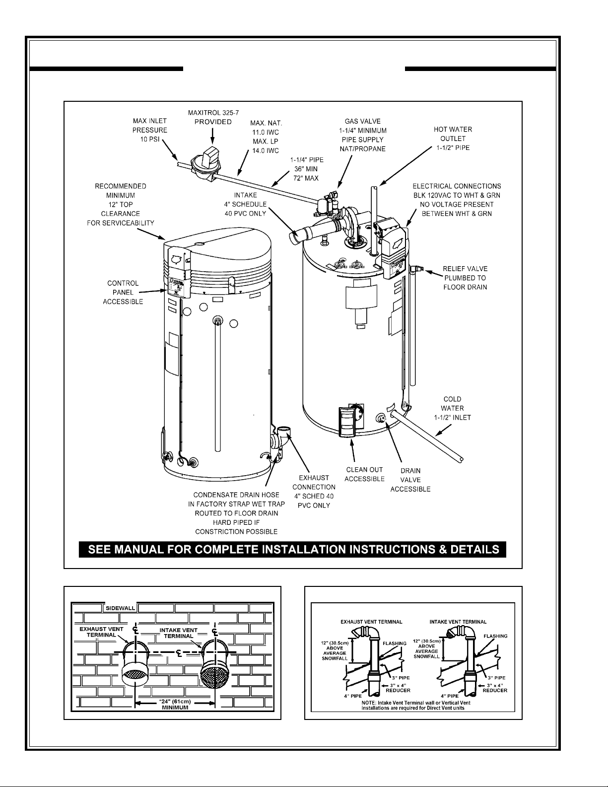
INSTALLATION INSTRUCTIONS
REQUIRED ABILITY
INSTALLATION OR SERVICE OF THIS WATER HEATER
REQUIRES ABILITY EQUIVALENT TO THAT OF A LICENSED
TRADESMAN IN THE FIELD INVOLVED. PLUMBING, AIR
SUPPL Y , VENTING, GAS SUPPLY AND ELECTRICAL WORK ARE
REQUIRED.
THE HEATER SHALL BE LOCATED OR PROTECTED SO IT IS
NOT SUBJECT TO PHYSICAL DAMAGE BY A MOVING VEHICLE.
DO NOT LOCATE THE HEATER WHERE NOISE FROM THE
EXHAUST OR INTAKE WILL BE OBJECTIONABLE. THIS
INCLUDES LOCATIONS CLOSE TO OR ACROSS FROM
WINDOWS AND DOORS. AVOID ANCHORING THE VENT AND
INTAKE PIPES DIRECTLY TO FRAMED WALLS, FLOORS OF
CEILINGS UNLESS RUBBER ISOLATION PIPE HANGERS ARE
USED. THIS PREVENTS ANY VIBRATIONS FROM BEING
TRANSMITTED INTO THE LIVING SPACES.
WARNING
FLAMMABLE ITEMS, PRESSURIZED CONTAINERS OR ANY
OTHER POTENTIAL FIRE HAZARDOUS ARTICLES MUST NEVER
BE PLACED ON OR ADJACENT TO THE HEATER. OPEN
CONTAINERS OF FLAMMABLE MATERIAL SHOULD NOT BE
STORED OR USED IN THE SAME ROOM WITH THE HEATER.
When installing the heater, consideration must be given to proper
location. Location selected should be as close to the intake
and exhaust termination points as practicable, with adequate
air supply and as centralized with the piping system as
possible.
INSULA TION BLANKETS
Insulation blankets available to the general public for external
use on gas water heaters are not approved for use on your A.O.
Smith water heater. The purpose of an insulation blanket is to
reduce the standby heat loss encountered with storage tank water
heaters. Your A.O. Smith water heater meets or exceeds the
ASHRAE/IES 90.1-1999 standards with respect to insulation and
standby loss requirements, making an insulation blanket
unnecessary.
WARNING
Should you choose to apply an insulation blanket to this heater,
you should follow these instructions. Failure to follow these
instructions can result in fire, asphyxiation, serious personal injury
or death.
• Do not apply insulation to the top, or the upper 15" (38 cm) of
the water heater, as this will interfere with safe operation.
• Do not cover the temperature & pressure relief valve.
• Do not cover the instruction manual. Keep it on the side of the
water heater or nearby for future reference.
• Do obtain new labels from A.O. Smith for placement on the
blanket directly over the existing labels.
THE HEATER MUST NOT BE LOCATED IN AN AREA WHERE IT
WILL BE SUBJECT TO FREEZING.
LOCATE IT NEAR A FLOOR DRAIN. THE HEA TER SHOULD BE
LOCATED IN AN AREA WHERE LEAKAGE FROM THE HEA TER
OR CONNECTIONS WILL NOT RESULT IN DAMAGE TO THE
ADJACENT AREA OR TO LOWER FLOORS OF THE
STRUCTURE.
When such locations cannot be avoided, it is recommended that a
suitable drain pan, adequately drained, be installed under the
appliance.
WARNING
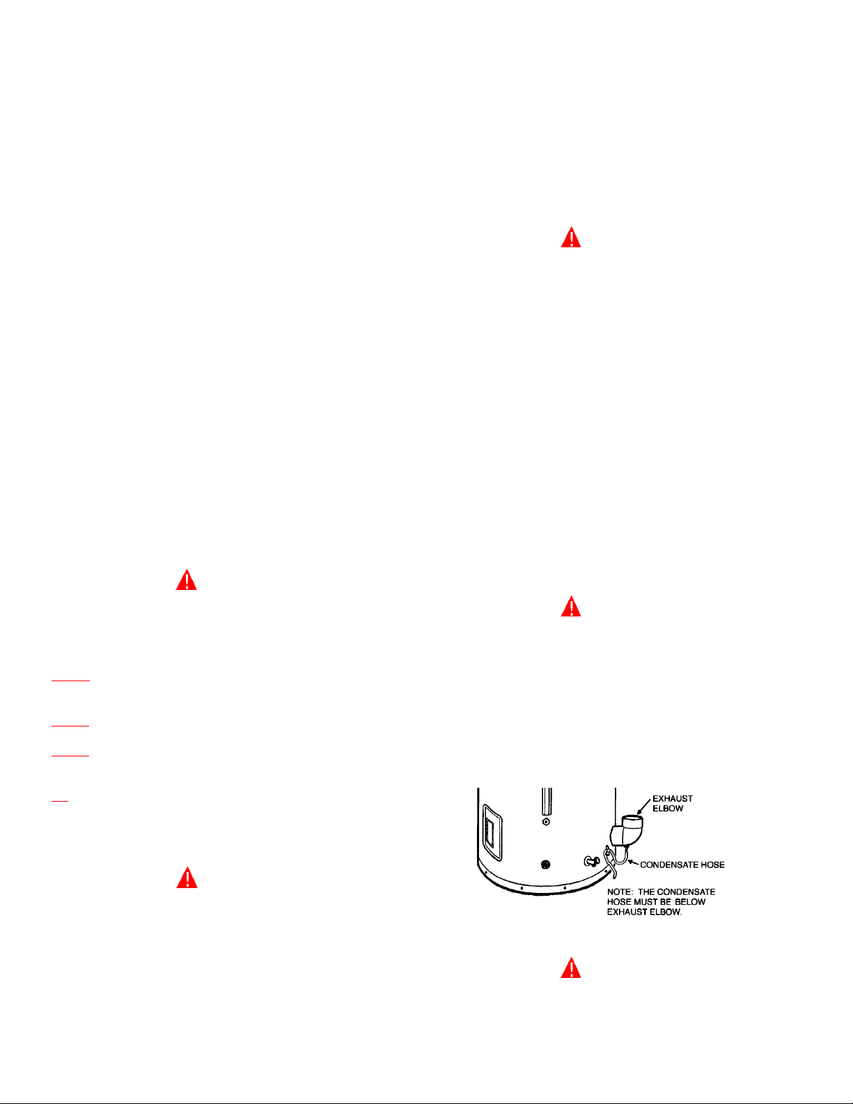
THIS WA TER HEA TER IS A CONDENSING UNIT AND REQUIRES
A DRAIN TO BE LOCATED IN CLOSE PROXIMITY TO ALLOW
THE CONDENSATE TO DRAIN SAFELY. THE CONDENSATE
DRAINS FROM THE UNIT AT THE EXHAUST ELBOW LOCATED
AT THE BOTTOM OF THE UNIT. NOTE: IT IS IMPORTANT THAT
THE CONDENSATE HOSE NOT BE ELEVATED ABOVE THE
EXHAUST ELBOW (SEE FIGURE 3). THE CONDENSATE BUILDUP WILL BLOCK THE EXHAUST OUTLET, WHICH WILL CAUSE
IMPROPER OPERATION.
LOCATING THE HEATER
WARNING
THERE IS A RISK IN USING FUEL BURNING APPLIANCES SUCH
AS GAS WATER HEATERS IN ROOMS, GARAGES OR OTHER
AREAS WHERE GASOLINE, OTHER FLAMMABLE LIQUIDS OR
ENGINE DRIVEN EQUIPMENT OR VEHICLES ARE STORED,
OPERATED OR REPAIRED. FLAMMABLE V APORS ARE HEA VY
AND TRA VEL ALONG THE FLOOR AND MA Y BE IGNITED BY THE
HEA TER’S IGNITER OR MAIN BURNER FLAMES CAUSING FIRE
OR EXPLOSION. SOME LOCAL CODES PERMIT OPERA TION OF
GAS APPLIANCES IF INSTALLED 18 INCHES (46 cm) OR MORE
ABOVE THE FLOOR. THIS MA Y REDUCE THE RISK IF LOCA TION
IN SUCH AN AREA CANNOT BE AVOIDED.
FIGURE 3.
WARNING
DO NOT USE THIS APPLIANCE IF ANY P ART HAS BEEN UNDER
WATER. IMMEDIATELY CALL A QUALIFIED SERVICE
TECHNICIAN TO INSPECT THE APPLIANCE AND TO REPLACE
ANY PART OF THE CONTROL SYSTEM AND ANY GAS
CONTROL WHICH HAS BEEN UNDER W ATER.
6
CLEARANCES
These heaters are approved for installation on combustible flooring
in an alcove when the minimum clearances from any combustion
construction are followed as indicated in Figure 4.
SERIOUS DAMAGE TO THE HEATER AND RISK OF FIRE OR
EXPLOSION. IT CAN ALSO CREATE A RISK OF ASPHYXIA TION.
UNCONFINED SPACE
In all installations the minimum combustible clearances from any
vent piping shall be 0". Vent piping passing through a combustible
wall or ceiling must be a continuous run (no joints).
A service clearance of 24" (61 cm) should be maintained from
serviceable parts such as relief valves, thermostats, cleanout
openings, drain valves and venting connections.
Always disconnect electrical power before servicing the unit
*ILLUSTRATION OF MINIMUM COMBUSTIBLE CLEARANCES IN AN ALCOVE.
FIGURE 4.
HARD W A TER
Where hard water conditions exist, water softening or the threshold
type of water treatment is recommended. This will protect the
dishwashers, coffee urns, water heaters, water piping and other
equipment.
See MAINTENANCE section for details of tank cleanout procedure.
In buildings of conventional frame, brick or stone construction,
unconfined spaces may provide adequate air for combustion and
ventilation.
If the unconfined space is within a building of tight construction
(buildings using the following construction: weather stripping, heavy
insulation, caulking, vapor barrier, etc.), air for combustion and
ventilation must be obtained from outdoors. The installation
instructions for confined spaces in tightly constructed buildings
must be followed to ensure adequate air supply.
CONFINED SP ACE
When drawing combustion air from inside a conventionally
constructed building to a confined space, such a space shall be
provided with two permanent openings, ONE IN OR WITHIN
12 INCHES (31 cm) OF THE ENCLOSURE TOP AND ONE IN OR
WITHIN 12 INCHES (31 cm) OF THE ENCLOSURE BOTTOM.
Each opening shall have a free area of at least one square inch per
1000 Btuh (2,203mm
less than 100 square inches (645 cm²).
If the confined space is within a building of tight construction, air for
combustion and ventilation must be obtained from outdoors. When
directly communicating with the outdoors through vertical ducts, two
permanent openings, located in the above manner, shall be provided.
Each opening shall have a free area of not less than one square inch
per 4000 Btuh (551mm
enclosure. If horizontal ducts are used, each opening shall have a
free area of not less than one square inch per
2000 Btuh (1,102mm
enclosure.
2
/kW) appliances in the enclosure, but not
2
/kW) of the total input of all appliances in the
2
/kW) of the total input of all appliances in the
AIR REQUIREMENTS
KEEP APPLIANCE AREA CLEAR AND FREE OF COMBUSTIBLE
MATERIALS, GASOLINE AND OTHER FLAMMABLE V APORS AND
LIQUIDS.
DO NOT OBSTRUCT THE FLOW OF COMBUSTION AND
VENTILATING AIR.
WARNING
FOR SAFE OPERATION PROVIDE ADEQUATE AIR FOR
COMBUSTION AND VENTILATION. AN INSUFFICIENT SUPPLY
OF AIR WILL CAUSE RECIRCULATION OF COMBUSTION
PRODUCTS RESULTING IN CONTAMINATION THAT MAY BE
HAZARDOUS TO LIFE. SUCH A CONDITION OFTEN WILL RESULT
IN A YELLOW , LUMINOUS BURNER FLAME, CAUSING CARBONING
OR SOOTING OF THE COMBUSTION CHAMBER, BURNERS AND
FLUE TUBES AND CREATES A RISK OF ASPHYXIATION.
MECHANICAL EXHAUSTING OF ROOM AIR
Where an exhaust fan is installed in the same room with a heater,
sufficient openings for air must be provided in the walls.
UNDERSIZED OPENINGS WILL CAUSE AIR TO BE DRAWN
INTO THE ROOM THROUGH THE HEATER’S VENTING SYSTEM,
CAUSING POOR COMBUSTION. SOOTING MAY RESULT IN
CHEMICAL VAPOR CORROSION
WARNING
CORROSION OF THE FLUE WAYS AND VENT SYSTEM MAY
OCCUR IF AIR FOR COMBUSTION CONTAINS CERTAIN
CHEMICAL VAPORS. SUCH CORROSION MAY RESULT IN
FAILURE AND RISK OF ASPHYXIA TION.
Spray can propellants, cleaning solvents, refrigerator and air
conditioning refrigerants, swimming pool chemicals, calcium and
sodium chloride, waxes, and process chemicals are typical
compounds which are potentially corrosive.
PRODUCTS OF THIS SORT SHOULD NOT BE STORED NEAR
THE HEATER. ALSO, AIR WHICH IS BROUGHT IN CONT ACT WITH
THE HEATER SHOULD NOT CONTAIN ANY OF THESE
CHEMICALS. IF NECESSARY , UNCONT AMINA TED AIR SHOULD
BE OBTAINED FROM REMOTE OR OUTSIDE SOURCES.
VENTING
WARNING
THE INSTRUCTIONS IN THIS SECTION ON VENTING MUST BE
FOLLOWED TO AVOID CHOKED COMBUSTION OR
RECIRCULATION OF FLUE GASES. SUCH CONDITIONS CAUSE
SOOTING OR RISKS OF FIRE AND ASPHYXIA TION.
7
US DIRECT VENT
TO PREVENT EXHAUSTING PRODUCTS FROM CIRCULA TING TO THE
AIR INTAKE IN WINDY/COLD AREAS, THE MAXIMUM PRACTICAL
DISTANCE BETWEEN THESE TWO TERMINALS IS RECOMMENDED.
CANADIAN DIRECT VENT
CAUTION
FIGURE 5.
8
US HORIZONTAL VENT
TO PREVENT EXHAUSTING PRODUCTS FROM CIRCULA TING TO THE
AIR INTAKE IN WINDY/COLD AREAS, THE MAXIMUM PRACTICAL
DISTANCE BETWEEN THESE TWO TERMINALS IS RECOMMENDED.
CANADIAN HORIZONTAL VENT
CAUTION
FIGURE 6.
9
Heater must be protected from freezing downdrafts during
shutdown periods.
WARNING
NEVER OPERATE THE HEATER UNLESS IT IS VENTED TO
THE OUTDOORS AND HAS ADEQUA TE AIR SUPPLY TO A VOID
RISKS OF IMPROPER OPERATION, FIRE, EXPLOSION OR
ASPHYXIATION.
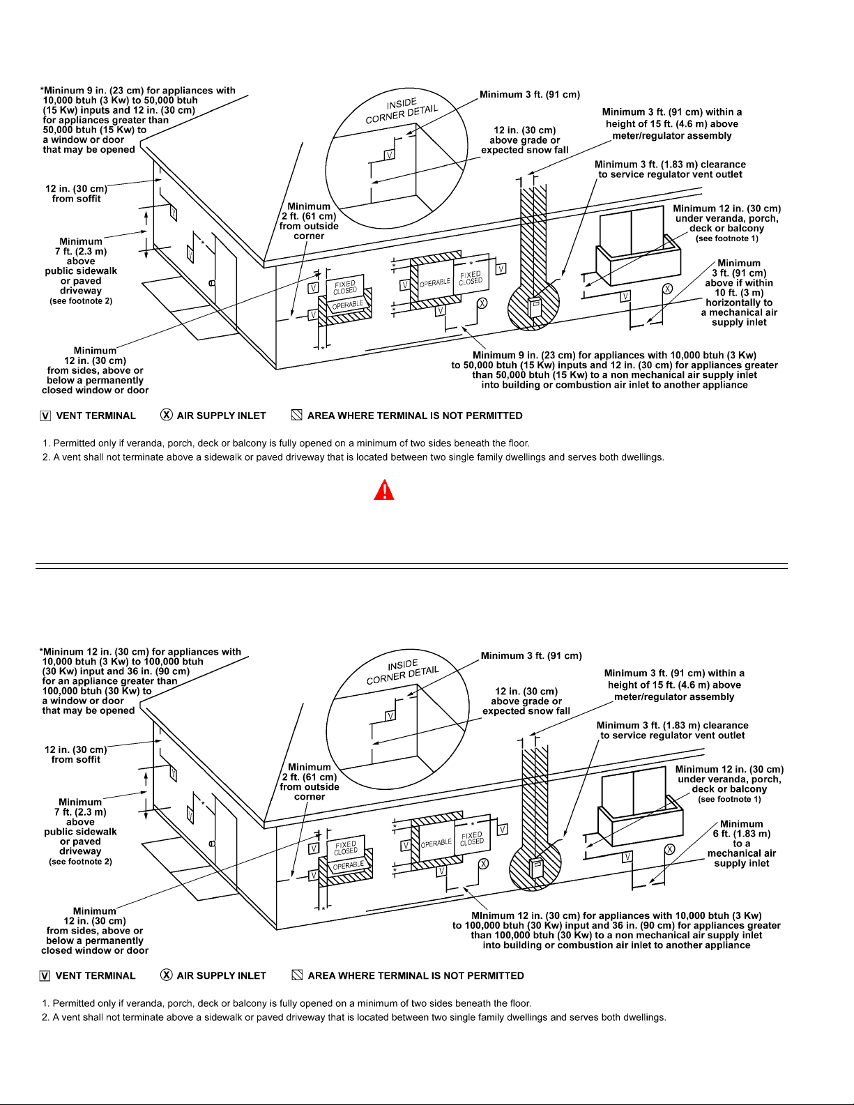
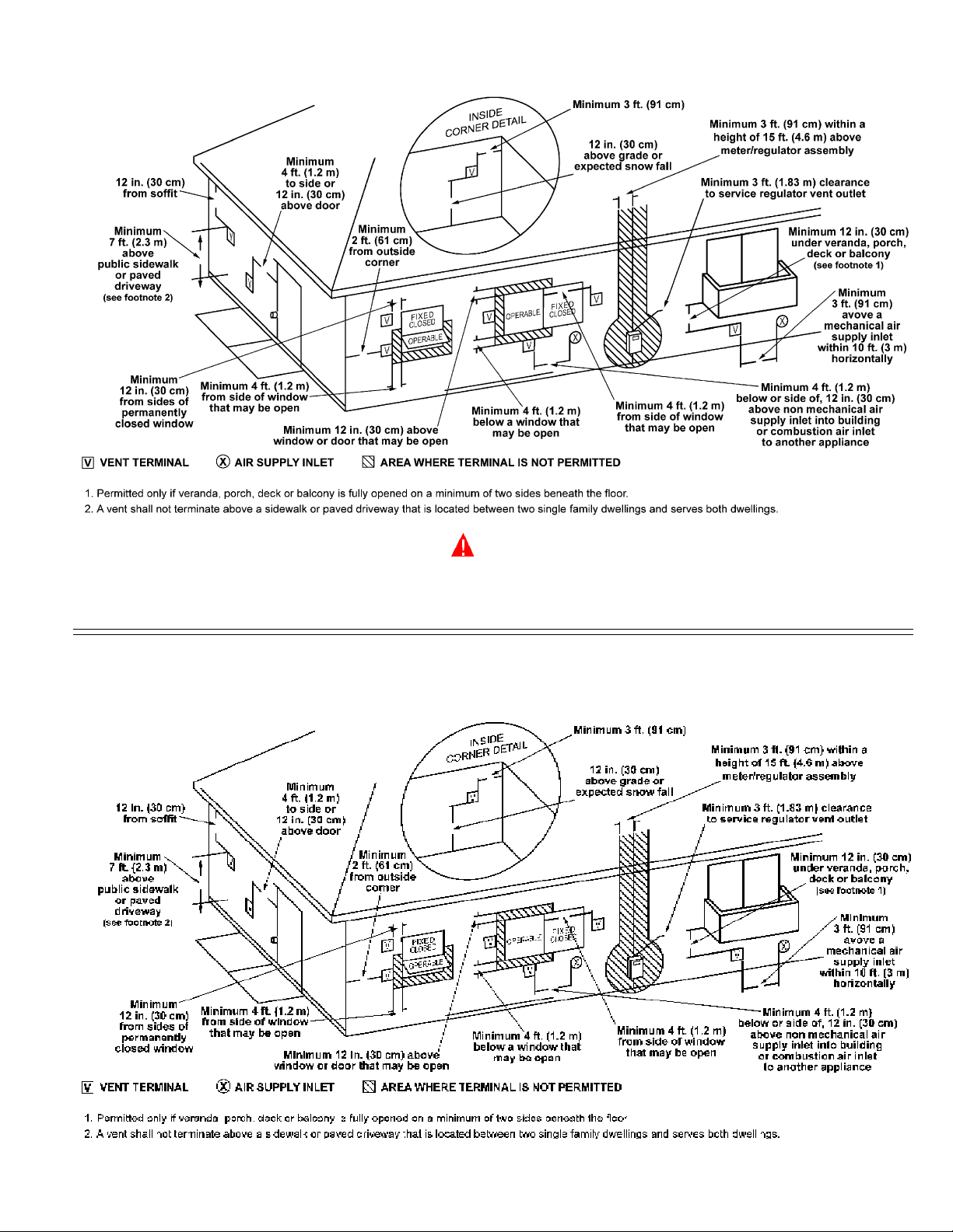
VENT PIPE TERMINATION
3"x 4" 45° PVC ELBOW WITH INT AKE GUARD
FIGURE 7.
NOTE: Before installing venting, determine place of vent pipe
termination. See Figure 5 and 6 before proceeding.
CAUTION
DO NOT TERMINA TE THE VENTING WHERE NOISE FROM THE
EXHAUST OR INTAKE WILL BE OBJECTIONABLE. THIS
INCLUDES LOCATIONS CLOSE TO OR ACROSS FROM WINDOWS
AND DOORS. A VOID ANCHORING THE VENT AND INT AKE PIPES
DIRECTLY TO FRAMED W ALLS, FLOORS OR CEILINGS UNLESS
RUBBER ISOLATION PIPE HANGERS ARE USED. THIS
PREVENTS ANY VIBRATIONS FROM BEING TRANSMITTED INTO
THE LIVING SPACES.
IMPORT ANT
The vent system must terminate so that proper clearances are
maintained as cited in local codes or the current editions of
the National Fuel Gas Code, ANSI Z223.1/NFPA 54 or the
Canadian Electrical Code, CSA C22.1.
Do not terminate the exhaust vent terminal over public area where
condensate or vapor can cause nuisance or hazard.
Plan the vent system layout so that proper clearances are
maintained from plumbing and wiring.
W ARNING
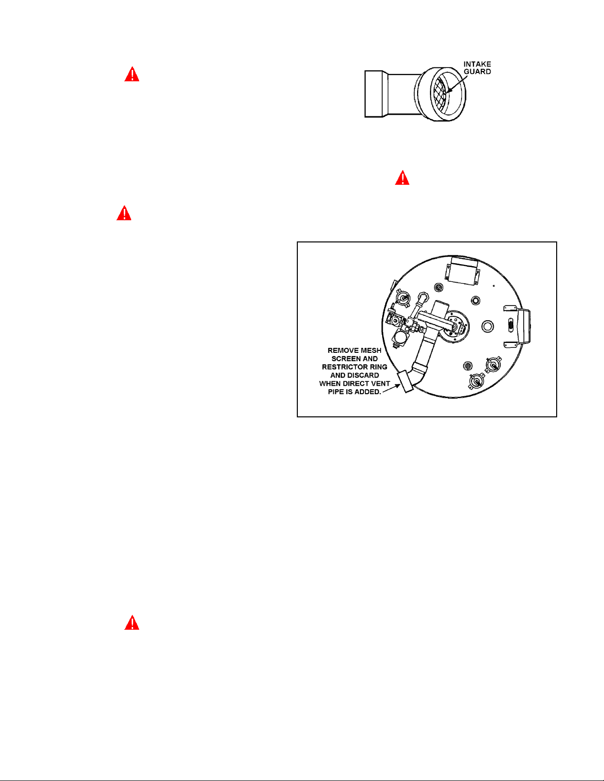
WHEN THE UNIT IS TO BE SETUP AS A DIRECT VENT , THE INT AKE
GUARD MUST BE REMOVED. THE INLET VENT PIPE MA Y THEN
BE GLUED TO THE AIR INTAKE (see Figure 8) PROVIDED ON
THE UNIT.
FIGURE 8.
DIRECT VENT TERMINAL INSTALLATION
Vent pipes serving power vented appliances are classified by
building codes as "vent connectors". Required clearances from
combustible materials must be provided in accordance with
information in this manual under LOCATION OF HEATER and
CLEARANCES, and with National Fuel Gas Code and local Codes.
IMPORT ANT
Plan the layout of the vent system backwards from the vent
termination to the appliance.
WARNING
USE ONLY THE VENT TERMINALS SUPPLIED WITH THIS UNIT.
TERMINATION OF A VENT SYSTEM WITH A DEVICE OTHER THAN
THE SUPPLIED VENT TERMINATIONS WILL AFFECT SYSTEM
PERFORMANCE AND RESULT IN A SAFETY HAZARD.
DIRECT VENTING
The air intake provided on the unit contains an intake guard,
see Figure 7.
IMPORT ANT
THIS UNIT CONSISTS OF TWO VENT TERMINALS - AN INTAKE
VENT TERMINAL AND AN EXHAUST VENT TERMINAL. THE INT AKE
VENT TERMINAL IS A 3" 45° PVC ELBOW WITH A DOME SHAPE
SCREEN AND THE EXHAUST VENT TERMINAL IS A 3" 45°PVC
ELBOW WITH A MESH WIRE SCREEN.
NOTE: TO PREVENT EXHAUSTING PRODUCTS FROM
CIRCULA TING TO THE AIR INT AKE IN WINDY/COLD AREAS, THE
MAXIMUM PRACTICAL DISTANCE BETWEEN THESE TWO
TERMINALS IS RECOMMENDED.
IMPORT ANT
WHEN LOCATING THE TERMINALS ON A SIDEWALL, THE
FOLLOWING SPECIFICATIONS PERTAINING TO TERMINAL
LOCA TION MUST BE FOLLOWED.
1. The intake vent terminal and the exhaust vent terminal must
terminate on the same exterior wall and must be located at a
minimum of 24" (61cm) from the vertical centerline of the exhaust
vent terminal (see Figure 9). In colder climates increasing the
24" (61cm) minimum to 48" (122cm) will reduce possibility of
frost over from side winds blowing exhaust vapors to the air
intake of the direct the vent and is recommended for Canada.
10
2. The horizontal centerline of the intake vent terminal may not be
located lower than the horizontal centerline of the exhaust vent
terminal (see Figure 9).
FIGURE 9.
INSTALLATION SEQUENCE
For installations in the City of Los Angeles, California Category IV
PVC Pipe such as that manufactured by Brownline Pipe Company,
must be used as vent pipe material.
CAUTION
Vent terminals supplied with the heater must be used.
Slide the pipe through the wall and insert into coupling on the
other side of the wall, making sure that the vent terminal ends
up pointed in the correct position. See Figure 10.
EXHAUST VENT TERMINAL
NOTE: BEFORE BEGINNING INSTALLA TION OF ANY VENT PIPE
READ THE VENT PIPE MANUFACTURER'S INSTALLATION
INSTRUCTIONS.
1. After the points of termination have been determined, use the
cover plates as templates to mark the holes for the vent pipes to
be inserted through the wall. BEWARE OF CONCEALED
WIRING AND PIPING INSIDE OF W ALL.
2. If the vent terminals are being installed on the outside of a
finished wall, it may be easier to mark both the inside and outside
wall. Align the holes by drilling a hole through the center of the
template from the inside through to the outside. The template
can now be positioned on the outside wall using the drilled
holes as a centering point for the template.
3. A) MASONRY SIDE WALLS
Chisel an opening approximately 1/2" (1.3 cm) larger than the
marked circle.
B) WOODEN SIDE WALLS
Drill a pilot hole approximately one quarter inch outside of the
marked circle. This pilot hole is used as a starting point for a
saws-all or sabre saw blade. Cut around the marked circle
staying approximately one quarter inch outside of the line. (This
will allow the vent pipe to easily slide through the opening. The
resulting gap will be covered by the vent terminal cover plates.)
Repeat this step on the inside wall if necessary.
4. Cut a length of PVC pipe about 3.5" (8.9 cm) longer than the wall
thickness at the opening.
5. Glue the intake vent terminal to the section of the pipe.
6. Slide the wall plate over the pipe to stop against intake vent terminal.
7. Place a bead of caulking (not supplied) around the gap between
the pipe and the wall. Place some of the caulking on the back of
the plate to hold it against the wall after installation.
8. If the vent pipe is installed up to the wall, with a coupling on the
end against the wall opening, the pipe with the vent terminal
can be prepared for gluing before inserting through the wall.
INT AKE VENT TERMINAL
FIGURE 10.
VERTICAL VENT TERMINAL INSTALLATION
IMPORT ANT
WHEN TERMINATING THROUGH A ROOF, THE FOLLOWING
SPECIFICATIONS PER T AINING TO TERMINAL LOCA TION MUST
BE FOLLOWED.
1. Proper support must be provided for all pipe protruding through
the roof.
2. The vertical roof terminations should be sealed with a plumbing
roof boot or equivalent flashing.
3. The intake vent termination and the exhaust vent termination
must penetrate the same side of roof.
4. The center line of the intake vent termination and the center line
of the exhaust vent termination must be no closer than
24" (61cm).
5. The intake vent terminal and the exhaust vent terminal must be
oriented facing downward and the same direction.
The specifications are displayed in Figure 11.
NOTE: Exhaust vent terminal is installed using the same procedure.
INSTALLATION SEQUENCE
NOTE: BEFORE BEGINNING INSTALLA TION OF ANY VENT PIPE,
READ “VENT PIPE PREPARATION” SECTION ON PAGE 12.
1. After the points of termination have been determined, use the
cover plates as templates to mark the holes for the vent pipes
to be inserted through the roof.
11
 Loading...