


PART II
Technical Reference
53

4.1 Overview
Use the Dashboard screens to check status information about the NWA/WAC.
4.1.1 What You Can Do in this Chapter
• The main Dashboard screen (Section 4.2 on page 54) displays the NWA/WAC’s general device
information, system status, system resource usage, and interface status. You can also display other
status screens for more information.
4.2 Dashboard
CHAPTER 4
Dashboard
This screen is the first thing you see when you log into the NWA/WAC. It also appears every time you click
the Dashboard icon in the navigation panel. The Dashboard displays general device information, system
status, system resource usage, and interface status in widgets that you can re-arrange to suit your
needs. You can also collapse, refresh, and close individual widgets.
NWA / WAC Series User’s Guide
54
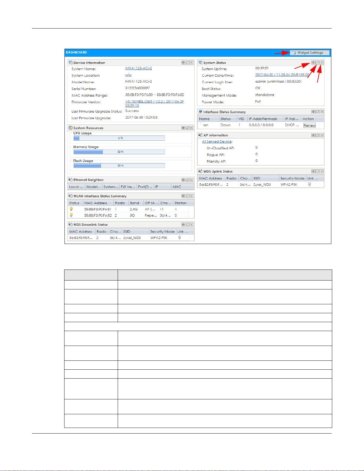
Figure 27 Dashboard
B
C
D
A
Chapter 4 Dashboard
The following table describes the labels in this screen.
Table 23 Dashboard
LABEL DESCRIPTION
Widget Settings (A) Use this link to re-open closed widgets. Widgets that are already open appear grayed out.
Refresh Time Setting
(B)
Refresh Now (C) Click this to update the widget’s information immediately.
Close Widget (D) Click this to close the widget. Use Widget Settings to re-open it.
Device Information
System Name This field displays the name used to identify the NWA/WAC on any network. Click the icon to
System Location This field displays the location of the NWA/WAC. Click the icon to open the screen where
Model Name This field displays the model name of this NWA/WAC.
Serial Number This field displays the serial number of this NWA/WAC.
MAC Address
Range
Firmware Version This field displays the version number and date of the firmware the NWA/WAC is currently
Last Firmware
Upgrade Status
Set the interval for refreshing the information displayed in the widget.
open the screen where you can change it.
you can change it.
This field displays the MAC addresses used by the NWA/WAC. Each physical port or wireless
radio has one MAC address. The first MAC address is assigned to the Ethernet LAN port, the
second MAC address is assigned to the first radio, and so on.
running. Click the icon to open the screen where you can upload firmware.
This field displays whether the latest firmware update was successfully completed.
NWA / WAC Series User’s Guide
55

Chapter 4 Dashboard
Table 23 Dashboard (continued)
LABEL DESCRIPTION
Last Firmware
Upgrade
System Resources
CPU Usage This field displays what percentage of the NWA/WAC’s processing capability is currently
Memory Usage This field displays what percentage of the NWA/WAC’s RAM is currently being used. Hover
Flash Usage This field displays what percentage of the NWA/WAC’s onboard flash memory is currently
Ethernet Neighbor
Local Port
(Description)
Model Name This field displays the model name of the discovered device.
System Name This field displays the system name of the discovered device.
FW Version This field displays the firmware version of the discovered device.
Port (Description) This field displays the discovered device’s port which is connected to the NWA/WAC.
IP This field displays the IP address of the discovered device. Click the IP address to access
MAC This field displays the MAC address of the discovered device.
WDS (Wireless Distribution System) Uplink/Downlink Status
MAC Address This field displays the MAC address of the root AP or repeater to which the NWA/WAC is
Radio This field displays the radio number on the root AP or repeater to which the NWA/WAC is
Channel This field displays the channel number on the root AP or repeater to which the NWA/WAC is
SSID This field displays the name of the wireless network to which the NWA/WAC is connected
Security Mode This field displays which secure encryption methods is being used by the NWA/WAC to
Link Status This field displays the RSSI (Received Signal Strength Indicator) and transmission/reception
System Status
System Uptime This field displays how long the NWA/WAC has been running since it last restarted or was
Current Date/
Time
Current Login
User
This field displays the date and time when the last firmware update was made.
being used. Hover your cursor over this field to display the Show CPU Usage icon that takes
you to a chart of the NWA/WAC’s recent CPU usage.
your cursor over this field to display the Show Memory Usage icon that takes you to a chart
of the NWA/WAC’s recent memory usage.
being used.
This field displays the port of the NWA/WAC, on which the neighboring device is discovered.
and manage the discovered device using its web configurator.
connected using WDS.
connected using WDS.
connected using WDS.
using WDS.
connect to the root AP or repeater using WDS.
rate of the wireless connection in WDS.
turned on.
This field displays the current date and time in the NWA/WAC. The format is yyyy-mm-dd
hh:mm:ss.
This field displays the user name used to log in to the current session, the amount of
reauthentication time remaining, and the amount of lease time remaining.
NWA / WAC Series User’s Guide
56

Chapter 4 Dashboard
Table 23 Dashboard (continued)
LABEL DESCRIPTION
Boot Status This field displays details about the NWA/WAC’s startup state.
OK - The NWA/WAC started up successfully.
Firmware update OK - A firmware update was successful.
Problematic configuration after firmware update - The application of the configuration
failed after a firmware upgrade.
System default configuration - The NWA/WAC successfully applied the system default
configuration. This occurs when the NWA/WAC starts for the first time or you intentionally
reset the NWA/WAC to the system default settings.
Fallback to lastgood configuration - The NWA/WAC was unable to apply the startupconfig.conf configuration file and fell back to the lastgood.conf configuration file.
Fallback to system default configuration - The NWA/WAC was unable to apply the
lastgood.conf configuration file and fell back to the system default configuration file
(system-default.conf).
Booting in progress - The NWA/WAC is still applying the system configuration.
Management
Mode
Power Mode This displays the NWA/WAC’s power status.
This shows whether the NWA/WAC is set to work as a stand alone AP.
Full - the NWA/WAC receives power using a power adaptor and/or through a PoE switch/
injector using IEEE 802.3at PoE plus.
Limited - the NWA/WAC receives power through a PoE switch/injector using IEEE 802.3af PoE
even when it is also connected to a power source using a power adaptor.
When the NWA/WAC is in limited power mode, the NWA/WAC throughput decreases and
has just one transmitting radio chain.
It always shows Full if the NWA/WAC does not support power detection. At the time of
writing, only the WAC6500 series APs support the power detection feature.
Interface Status
Summary
Name This field displays the name of each interface.
Status This field displays the current status of each interface. The possible values depend on what
VID This field displays the VLAN ID to which the interface belongs.
IP Addr/Netmask This field displays the current IP address and subnet mask assigned to the interface. If the IP
IP Assignment This field displays how the interface gets its IP address.
If an Ethernet interface does not have any physical ports associated with it, its entry is
displayed in light gray text. Click the Detail icon to go to a (more detailed) summary screen
of interface statistics.
type of interface it is.
Inactive - The Ethernet interface is disabled.
Down - The Ethernet interface is enabled but not connected.
Speed / Duplex - The Ethernet interface is enabled and connected. This field displays the
port speed and duplex setting (Full or Half).
address is 0.0.0.0, the interface is disabled or did not receive an IP address and subnet mask
via DHCP.
Static - This interface has a static IP address.
DHCP Client - This interface gets its IP address from a DHCP server.
Action If the interface has a static IP address, this shows n/a.
If the interface has a dynamic IP address, use this field to get or to update the IP address for
the interface. Click Renew to send a new DHCP request to a DHCP server.
NWA / WAC Series User’s Guide
57
Chapter 4 Dashboard
Table 23 Dashboard (continued)
LABEL DESCRIPTION
WLAN Interface
Status Summary
Status This displays whether or not the WLAN interface is activated.
MAC Address This displays the MAC address of the radio.
Radio This indicates the radio number on the NWA/WAC.
Band This indicates the wireless frequency band currently being used by the radio.
OP Mode This indicates the radio’s operating mode. Operating modes are AP (MBSSID), MON
Channel This indicates the channel number the radio is using.
Antenna This indicates the antenna orientation for the radio (Wall or Ceiling).
Station This displays the number of wireless clients connected to the NWA/WAC.
AP Information This shows a summary of connected wireless Access Points (APs).
All Sensed Device This sections displays a summary of all wireless devices detected by the network. Click the
Un-Classified AP This displays the number of detected unclassified APs.
Rogue AP This displays the number of detected rogue APs.
Friendly AP This displays the number of detected friendly APs.
This displays status information for the WLAN interface.
This shows - when the radio is in monitor mode.
(monitor), Root AP or Repeater.
This field is not available if the NWA/WAC does not allow you to adjust antenna orientation
for each radio using the web configurator or a physical switch. Refer to Table 1 on page 13
and Table 3 on page 15 to see if your NWA/WAC has an antenna switch.
link to go to the Monitor > Wireless > Detected Device screen.
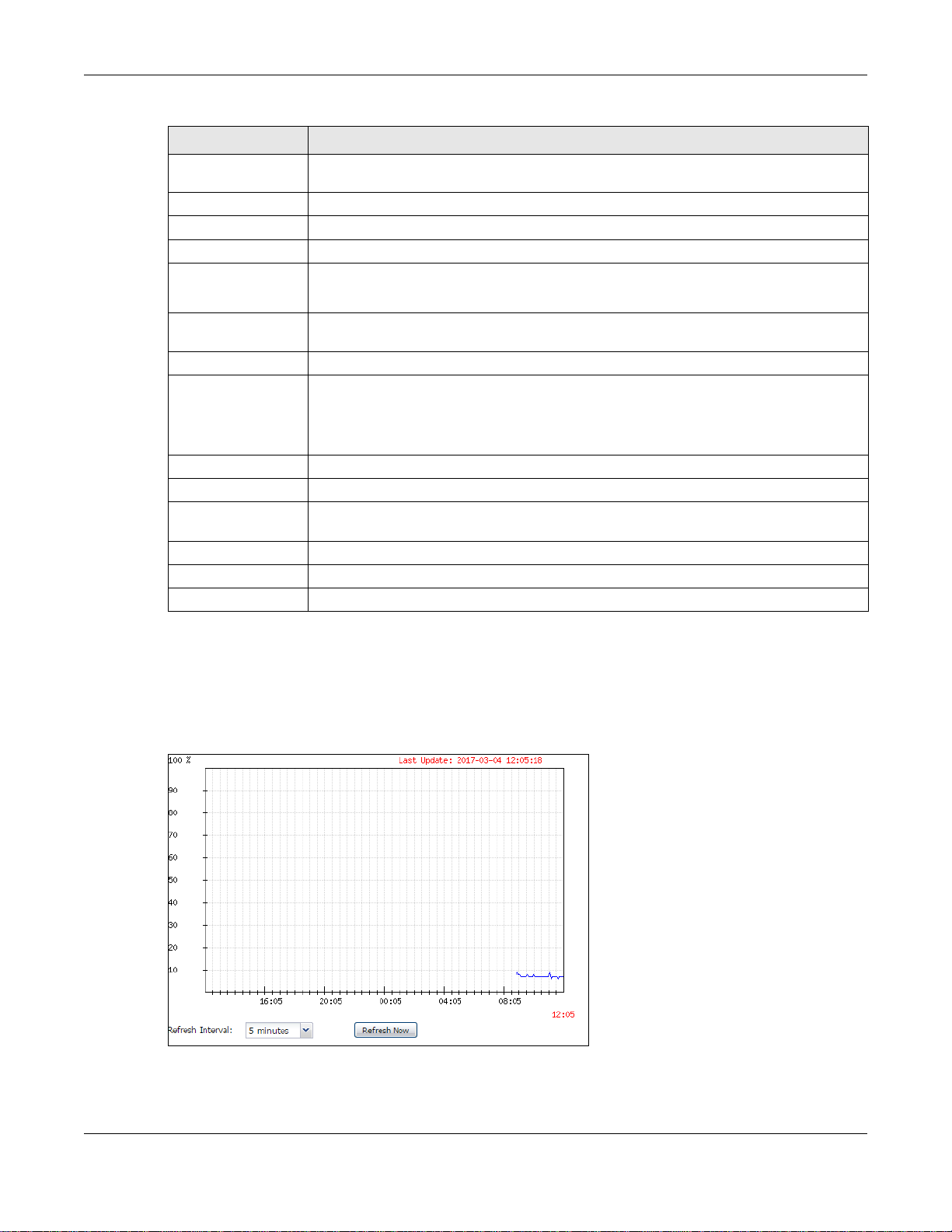
4.2.1 CPU Usage
Use this screen to look at a chart of the NWA/WAC’s recent CPU usage. To access this screen, click CPU
Usage in the dashboard.
Figure 28 Dashboard > CPU Usage
NWA / WAC Series User’s Guide
58
The following table describes the labels in this screen.
Table 24 Dashboard > CPU Usage
LABEL DESCRIPTION
% The y-axis represents the percentage of CPU usage.
time The x-axis shows the time period over which the CPU usage occurred
Refresh Interval Enter how often you want this window to be automatically updated.
Refresh Now Click this to update the information in the window right away.
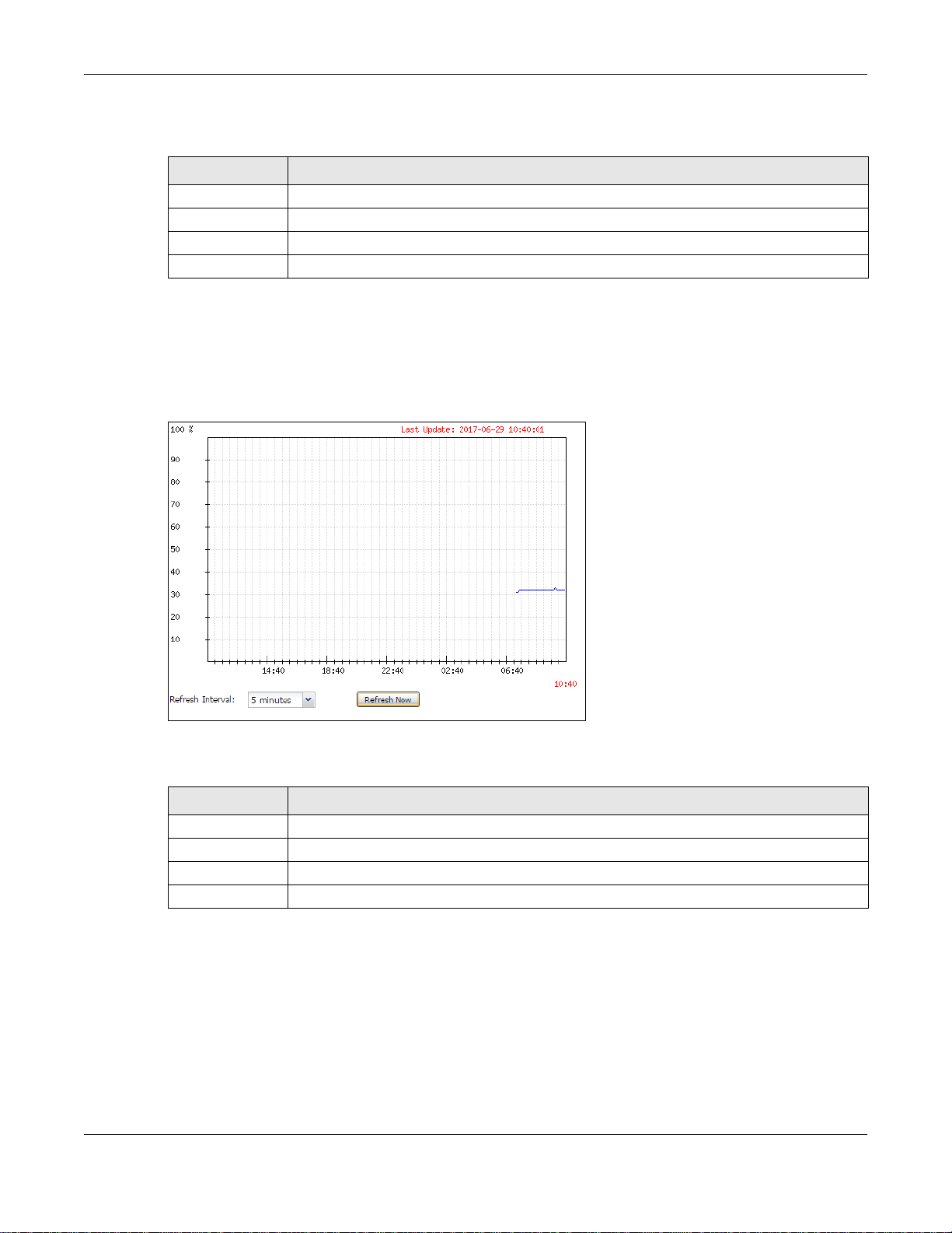
4.2.2 Memory Usage
Use this screen to look at a chart of the NWA/WAC’s recent memory (RAM) usage. To access this screen,
click Memory Usage in the dashboard.
Figure 29 Dashboard > Memory Usage
Chapter 4 Dashboard
The following table describes the labels in this screen.
Table 25 Dashboard > Memory Usage
LABEL DESCRIPTION
% The y-axis represents the percentage of RAM usage.
time The x-axis shows the time period over which the RAM usage occurred
Refresh Interval Enter how often you want this window to be automatically updated.
Refresh Now Click this to update the information in the window right away.
NWA / WAC Series User’s Guide
59

5.1 Overview
Use the Monitor screens to check status and statistics information.
5.1.1 What You Can Do in this Chapter
• The Network Status screen (Section 5.3 on page 61) displays general LAN interface information and
packet statistics.
• The AP Information > Radio List screen (Section 5.4 on page 64) displays statistics about the wireless
radio transmitters in the NWA/WAC.
• The Station Info screen (Section 5.5 on page 67) displays statistics pertaining to the associated
stations.
• The WDS Link Info screen (Section 5.6 on page 68) displays statistics about the NWA/WAC’s WDS
(Wireless Distribution System) connections.
• The Detected Device screen (Section 5.7 on page 69) displays information about suspected rogue
APs.
• The View Log screen (Section 5.8 on page 72) displays the NWA/WAC’s current log messages. You
can change the way the log is displayed, you can e-mail the log, and you can also clear the log in
this screen.
CHAPTER 5
Monitor
5.2 What You Need to Know
The following terms and concepts may help as you read through the chapter.
Rogue AP
Rogue APs are wireless access points operating in a network’s coverage area that are not under the
control of the network’s administrators, and can open up holes in a network’s security. See Chapter 11
on page 126 for details.
Friendly AP
Friendly APs are other wireless access points that are detected in your network, as well as any others that
you know are not a threat (those from neighboring networks, for example). See Chapter 11 on page 126
for details.
NWA / WAC Series User’s Guide
60
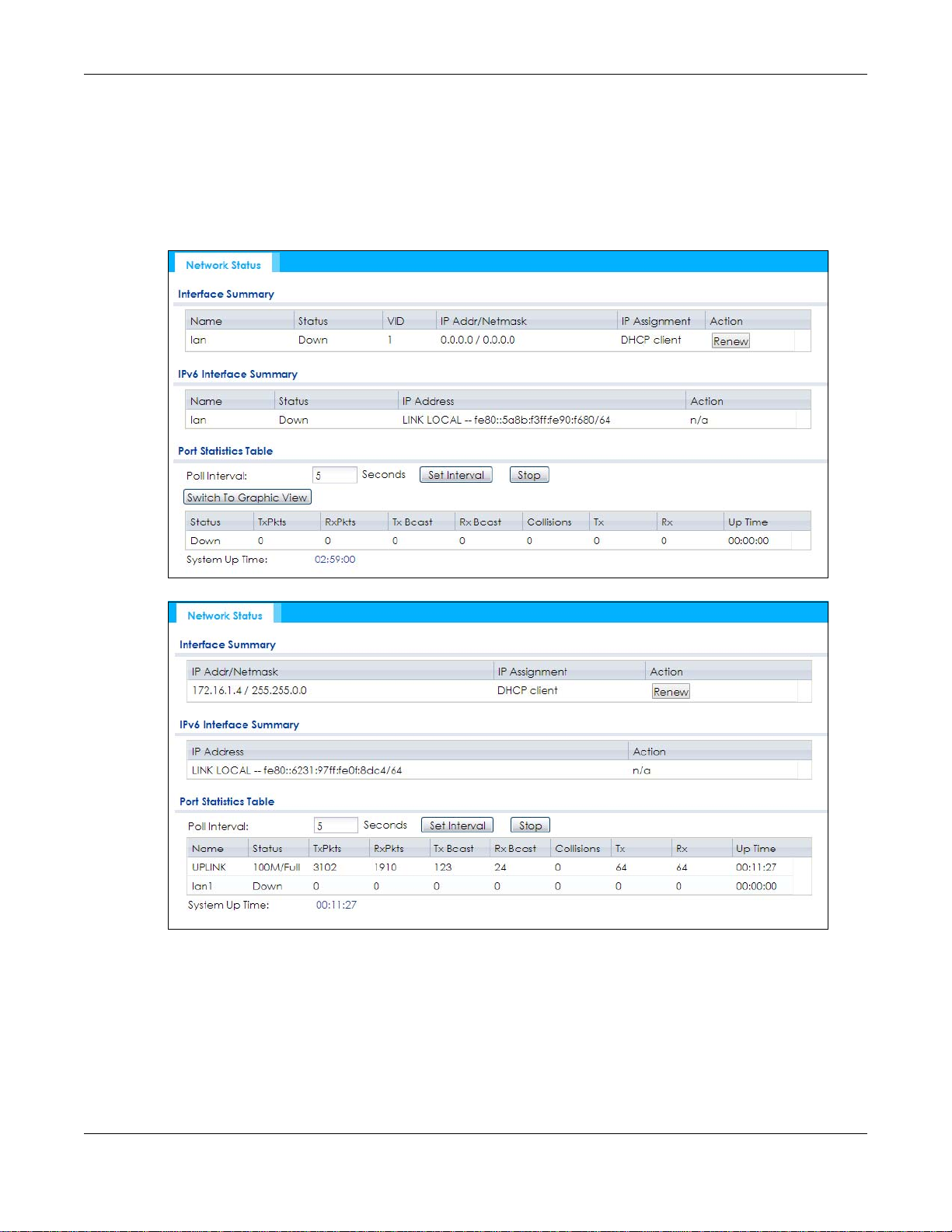
5.3 Network Status
Use this screen to look at general Ethernet interface information and packet statistics. To access this
screen, click Monitor > Network Status. The screen varies depending on whether the NWA/WAC has an
extra Ethernet port (except the uplink port).
Figure 30 Monitor > Network Status (for NWA/WAC with one Ethernet port)
Chapter 5 Monitor
Figure 31 Monitor > Network Status (for NWA/WAC with multiple Ethernet ports)
NWA / WAC Series User’s Guide
61

Chapter 5 Monitor
The following table describes the labels in this screen.
Table 26 Monitor > Network Status
LABEL DESCRIPTION
Interface
Summary
IPv6 Interface
Summary
Name This field displays the name of the physical Ethernet port on the NWA/WAC.
Status This field displays the current status of each physical port on the NWA/WAC.
VID This field displays the VLAN ID to which the port belongs.
IP Addr/Netmask
IP Address
IP Assignment This field displays how the interface gets its IPv4 address.
Use the Interface Summary section for IPv4 network settings. Use the IPv6 Interface Summary
section for IPv6 network settings if you connect your NWA/WAC to an IPv6 network. Both
sections have similar fields as described below.
Down - The port is not connected.
Speed / Duplex - The port is connected. This field displays the port speed and duplex setting
(Full or Half).
This field displays the current IP address (and subnet mask) of the interface. If the IP address is
0.0.0.0 (in the IPv4 network) or :: (in the IPv6 network), the interface does not have an IP address
yet.
Static - This interface has a static IPv4 address.
DHCP Client - This interface gets its IPv4 address from a DHCP server.
Action Use this field to get or to update the IP address for the interface. Click Renew to send a new
DHCP request to a DHCP server. If the interface cannot use one of these ways to get or to
update its IP address, this field displays n/a.
Port Statistics
Table
Poll Interval Enter how often you want this window to be updated automatically, and click Set Interval.
Set Interval Click this to set the Poll Interval the screen uses.
Stop Click this to stop the window from updating automatically. You can start it again by setting the
Poll Interval and clicking Set Interval.
Switch to Graphic
View
Name This field displays the name of the interface.
Status This field displays the current status of the physical port.
TxPkts This field displays the number of packets transmitted from the NWA/WAC on the physical port
RxPkts This field displays the number of packets received by the NWA/WAC on the physical port since
Tx Bcast This field displays the number of broadcast packets transmitted from the NWA/WAC on the
Rx Bcast This field displays the number of broadcast packets received by the NWA/WAC on the physical
Collisions This field displays the number of collisions on the physical port since it was last connected.
Tx This field displays the transmission speed, in bytes per second, on the physical port in the one-
Click this to display the port statistics as a line graph.
Down - The physical port is not connected.
Speed / Duplex - The physical port is connected. This field displays the port speed and duplex
setting (Full or Half).
since it was last connected.
it was last connected.
physical port since it was last connected.
port since it was last connected.
second interval before the screen updated.
NWA / WAC Series User’s Guide
62
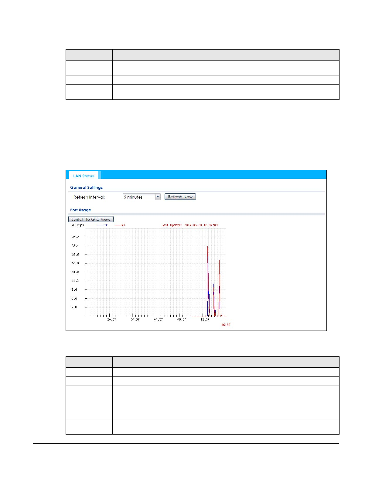
Table 26 Monitor > Network Status (continued)
LABEL DESCRIPTION
Rx This field displays the reception speed, in bytes per second, on the physical port in the one-
second interval before the screen updated.
Up Time This field displays how long the physical port has been connected.
System Up Time This field displays how long the NWA/WAC has been running since it last restarted or was turned
on.
5.3.1 Port Statistics Graph
Use the port statistics graph to look at a line graph of packet statistics for the Ethernet port. To view, click
Monitor > Network Status and then the Switch to Graphic View button.
This screen is NOT available on the NWA/WAC that has an extra Ethernet port (except the uplink port).
Figure 32 Monitor > Network Status > Switch to Graphic View
Chapter 5 Monitor
The following table describes the labels in this screen.
Table 27 Monitor > Network Status > Switch to Graphic View
LABEL DESCRIPTION
Refresh Interval Enter how often you want this window to be automatically updated.
Refresh Now Click this to update the information in the window right away.
Switch to Grid
View
Kbps/Mbps The y-axis represents the speed of transmission or reception.
Time The x-axis shows the time period over which the transmission or reception occurred.
TX This line represents traffic transmitted from the NWA/WAC on the physical port since it was last
Click this to display the port statistics as a table.
connected.
NWA / WAC Series User’s Guide
63
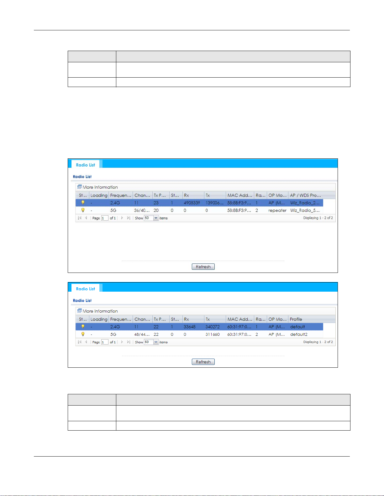
Table 27 Monitor > Network Status > Switch to Graphic View (continued)
LABEL DESCRIPTION
RX This line represents the traffic received by the NWA/WAC on the physical port since it was last
Last Update This field displays the date and time the information in the window was last updated.
5.4 Radio List
Use this screen to view statistics for the NWA/WAC’s wireless radio transmitters. To access this screen,
click Monitor > Wireless > AP Information > Radio List.
Figure 33 Monitor > Wireless > AP Information > Radio List (for NWA/WAC that supports WDS)
Chapter 5 Monitor
connected.
Figure 34 Monitor > Wireless > AP Information > Radio List (for NWA/WAC that doesn’t support WDS)
The following table describes the labels in this screen.
Table 28 Monitor > Wireless > AP Information > Radio List
LABEL DESCRIPTION
More Information Click this to view additional information about the selected radio’s wireless traffic and station
Status This displays whether or not the radio is enabled.
count. Information spans a 24 hour period.
NWA / WAC Series User’s Guide
64

Chapter 5 Monitor
Table 28 Monitor > Wireless > AP Information > Radio List (continued)
LABEL DESCRIPTION
Loading This indicates the AP’s load balance status (UnderLoad or OverLoad) when load balancing is
enabled on the NWA/WAC. Otherwise, it shows - when load balancing is disabled or the radio
is in monitor mode.
MAC Address This displays the MAC address of the radio.
Radio This indicates the radio number on the NWA/WAC to which it belongs.
OP Mode This indicates the radio’s operating mode. Operating modes are AP (MBSSID), MONITOR, Root
AP/WDS Profile This indicates the AP profile name and WDS profile name to which the radio belongs.
Profile This indicates the AP profile name to which the radio belongs.
Frequency Band This indicates the wireless frequency band currently being used by the radio.
Channel This indicates the radio’s channel ID.
Tx Power This displays the output power of the radio.
Station This displays the number of wireless clients connected to this radio on the NWA/WAC.
Rx This displays the total number of packets received by the radio.
Tx This displays the total number of packets transmitted by the radio.
AP or Repeater
This field is available only on the NWA/WAC that supports WDS.
This field is available only on the NWA/WAC that doesn’t support WDS.
This shows - when the radio is in monitor mode.
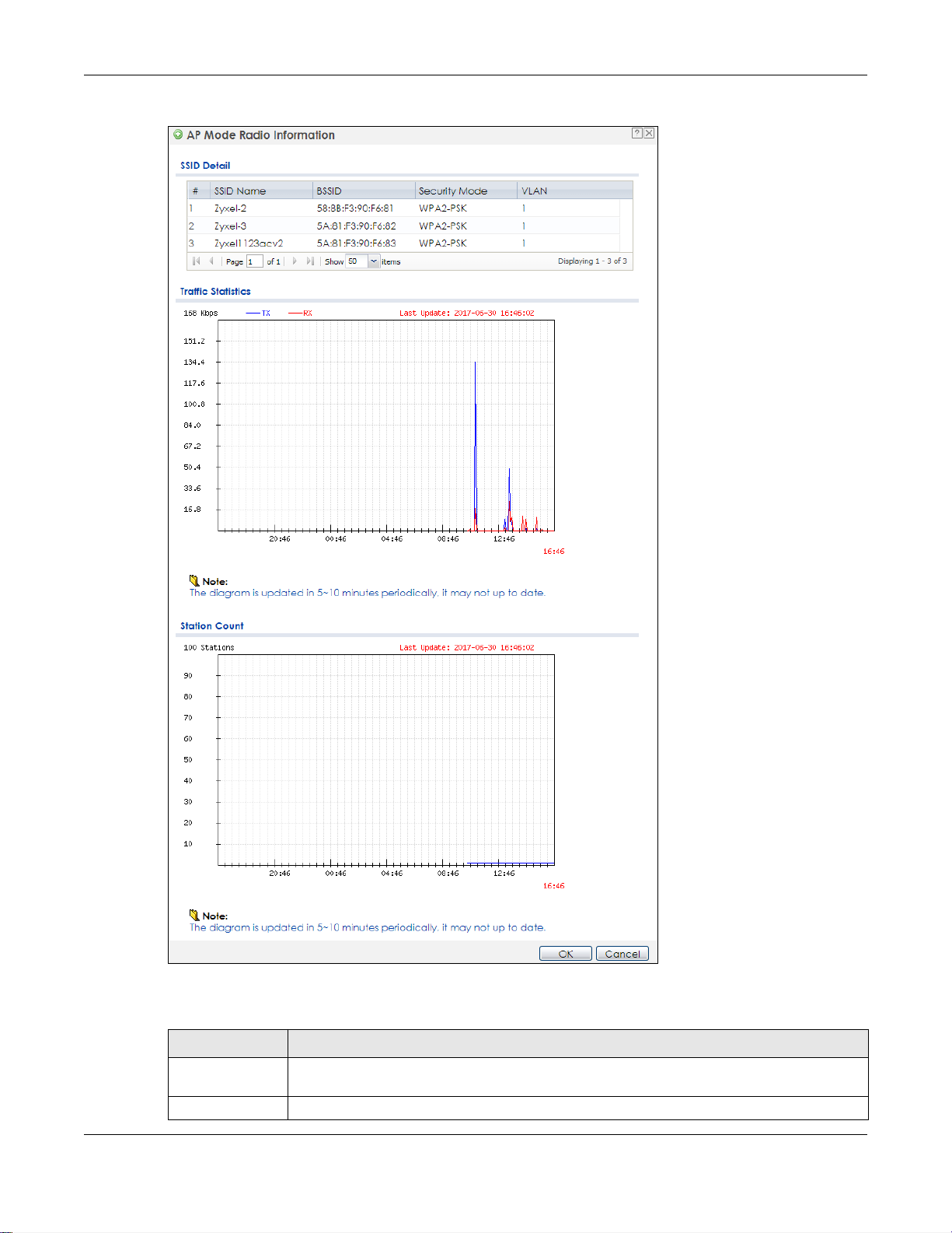
5.4.1 AP Mode Radio Information
This screen allows you to view a selected radio’s SSID details, wireless traffic statistics and station count
for the preceding 24 hours. To access this window, select a radio and click the More Information button
in the Radio List screen.
NWA / WAC Series User’s Guide
65
Chapter 5 Monitor
Figure 35 Monitor > Wireless > AP Information > Radio List > More Information
The following table describes the labels in this screen.
Table 29 Monitor > Wireless > AP Information > Radio List > More Information
LABEL DESCRIPTION
SSID Detail This list shows information about all the wireless clients that have connected to the specified
# This is the items sequential number in the list. It has no bearing on the actual data in this list.
radio over the preceding 24 hours.
NWA / WAC Series User’s Guide
66
Chapter 5 Monitor
Table 29 Monitor > Wireless > AP Information > Radio List > More Information (continued)
LABEL DESCRIPTION
SSID Name This displays an SSID associated with this radio. There can be up to eight maximum.
BSSID This displays a BSSID associated with this radio. The BSSID is tied to the SSID.
Security
Mode
VLAN This displays the VLAN ID associated with the SSID.
Traffic Statistics This graph displays the overall traffic information of the radio over the preceding 24 hours.
Kbps/Mbps This y-axis represents the amount of data moved across this radio in megabytes per second.
Time This x-axis represents the amount of time over which the data moved across this radio.
Station Count This graph displays the connected station information of the radio over the preceding 24 hours
Stations The y-axis represents the number of connected stations.
Time The x-axis shows the time period over which a station was connected.
Last Update This field displays the date and time the information in the window was last updated.
OK Click this to close this window.
Cancel Click this to close this window.
This displays the security mode in which the SSID is operating.
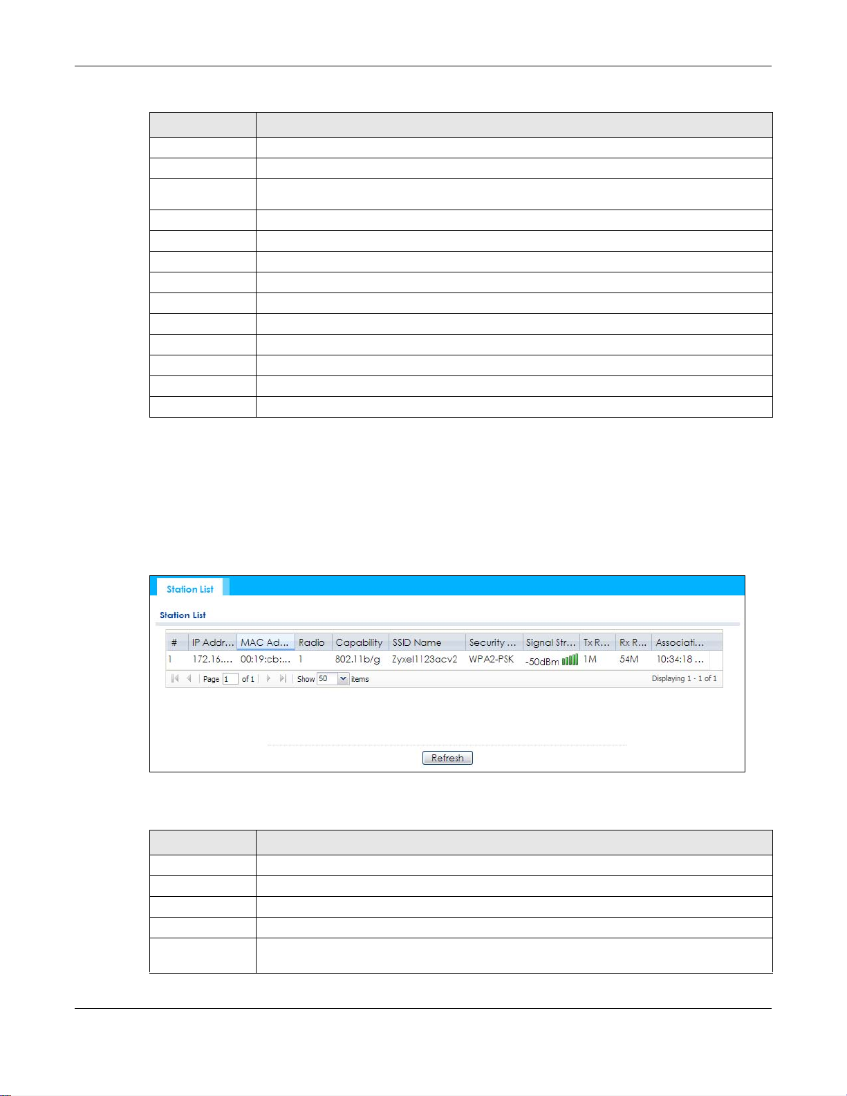
5.5 Station List
Use this screen to view statistics pertaining to the associated stations (or “wireless clients”). Click Monitor
> Wireless > Station Info to access this screen.
Figure 36 Monitor > Wireless > Station Info
The following table describes the labels in this screen.
Table 30 Monitor > Wireless > Station Info
LABEL DESCRIPTION
# This is the station’s index number in this list.
IP Address This is the station’s IP address.
MAC Address This is the station’s MAC address.
Radio This is the radio number on the NWA/WAC to which the station is connected.
Capability This displays the supported standard currently being used by the station or the standards
supported by the station.
NWA / WAC Series User’s Guide
67
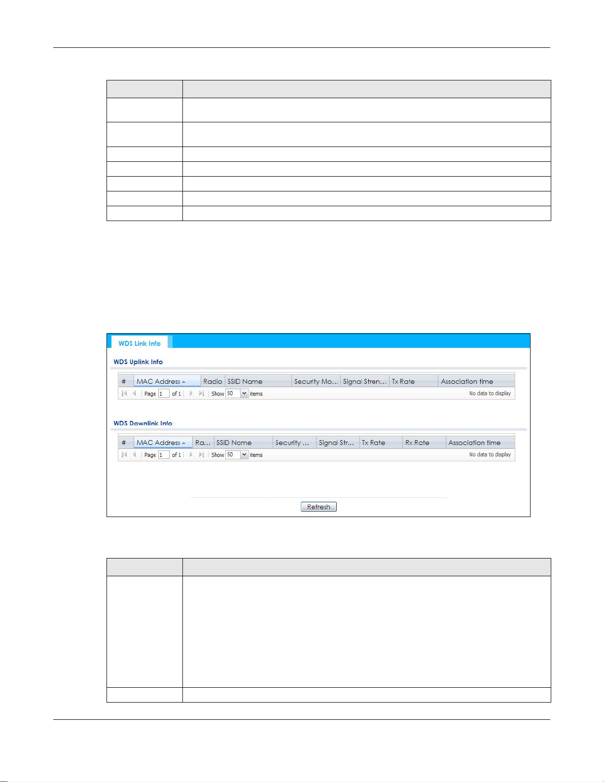
Table 30 Monitor > Wireless > Station Info (continued)
LABEL DESCRIPTION
SSID Name This indicates the name of the wireless network to which the station is connected. A single AP
can have multiple SSIDs or networks.
Security Mode This indicates which secure encryption methods is being used by the station to connect to the
network.
Signal Strength This is the RSSI (Received Signal Strength Indicator) of the station’s wireless connection.
Tx Rate This is the maximum transmission rate of the station.
Rx Rate This is the maximum reception rate of the station.
Association Time This displays the time the station first associated with the NWA/WAC’s wireless network.
Refresh Click this to refresh the items displayed on this page.
5.6 WDS Link Info
Use this screen to view the WDS traffic statistics between the NWA/WAC and a root AP or repeaters.
Click Monitor > Wireless > WDS Link Info to access this screen.
Chapter 5 Monitor
Figure 37 Monitor > Wireless > WDS Link Info
The following table describes the labels in this screen.
Table 31 Monitor > Wireless > WDS Link Info
LABEL DESCRIPTION
WDS Uplink Info
WDS Downlink
Info
# This is the index number of the root AP or repeater in this list.
Uplink refers to the WDS link from the repeaters to the root AP.
Downlink refers to the WDS link from the root AP to the repeaters.
When the NWA/WAC is in root AP mode and connected to a repeater, only the downlink
information is displayed.
When the NWA/WAC is in repeater mode and connected to a root AP directly or via another
repeater, the uplink information is displayed.
When the NWA/WAC is in repeater mode and connected to a root AP and other repeater(s),
both the uplink and downlink information would be displayed.
NWA / WAC Series User’s Guide
68

Chapter 5 Monitor
Table 31 Monitor > Wireless > WDS Link Info (continued)
LABEL DESCRIPTION
MAC Address This is the MAC address of the root AP or repeater to which the NWA/WAC is connected using
WDS.
Radio This is the radio number on the root AP or repeater to which the NWA/WAC is connected using
WDS.
SSID Name This indicates the name of the wireless network to which the NWA/WAC is connected using
Security Mode This indicates which secure encryption methods is being used by the NWA/WAC to connect to
Signal Strength This is the RSSI (Received Signal Strength Indicator) of the wireless connection in WDS.
Tx Rate This is the maximum transmission rate of the root AP or repeater to which the NWA/WAC is
Rx Rate This is the maximum reception rate of the root AP or repeater to which the NWA/WAC is
Association Time This displays the time the NWA/WAC first associated with the wireless network using WDS.
Refresh Click this to refresh the items displayed on this page.
WDS.
the root AP or repeater using WDS.
connected using WDS.
connected using WDS.
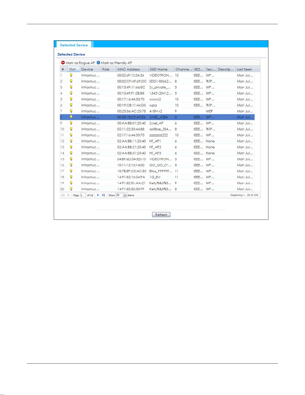
5.7 Detected Device
Use this screen to view information about suspected rogue APs. Click Monitor > Wireless > Detected
Device to access this screen. Not all NWA/WACs support monitor mode.
Note: If the NWA/WAC supports monitor mode, the radio or at least one of the NWA/WAC’s
radio must be set to monitor mode (in the Wireless > AP Management screen) in order
to detect other wireless devices in its vicinity.
If the NWA/WAC doesn’t support monitor mode, turn on rogue AP detection in the
Configuration > Wireless > Rogue AP screen to detect rogue APs.
NWA / WAC Series User’s Guide
69
Chapter 5 Monitor
Figure 38 Monitor > Wireless > Detected Device (for NWA/WAC that supports Monitor mode)
NWA / WAC Series User’s Guide
70
Chapter 5 Monitor
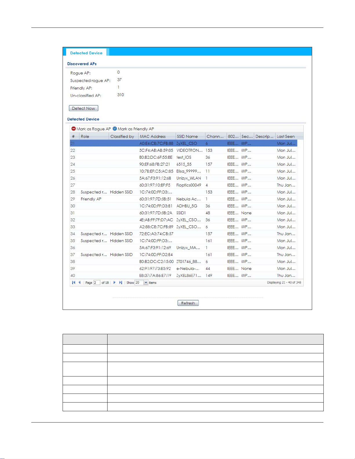
Figure 39 Monitor > Wireless > Detected Device (for NWA/WAC that doesn’t support Monitor mode)
The following table describes the labels in this screen.
Table 32 Monitor > Wireless > Detected Device
LABEL DESCRIPTION
Discovered APs
Rogue AP This shows how many devices are detected as rogue APs.
Suspected rogue APThis shows how many devices are detected as possible rogue APs by classification rule.
Friendly AP This shows how many devices are detected as friendly APs.
Un-classified AP This shows how many devices are detected, but have not been classified by the NWA/WAC.
Detect Now Click this button for the NWA/WAC to scan for APs in the network.
Detected Device
NWA / WAC Series User’s Guide
71

Chapter 5 Monitor
Table 32 Monitor > Wireless > Detected Device (continued)
LABEL DESCRIPTION
Mark as Rogue APClick this button to mark the selected AP as a rogue AP. A rogue AP can be contained in the
Configuration > Wireless > Rogue AP screen (Section 7.3 on page 88).
Mark as Friendly APClick this button to mark the selected AP as a friendly AP. For more on managing friendly APs,
see the Configuration > Wireless > Rogue AP screen (Section 7.3 on page 88).
# This is the detected device’s index number in this list.
Status This indicates the detected device’s status.
Device This indicates the type of device detected.
Role This indicates the detected device’s role (such as friendly or rogue).
Classified by This indicates the detected device’s classification rule.
MAC Address This indicates the detected device’s MAC address.
SSID Name This indicates the detected device’s SSID.
Channel ID This indicates the detected device’s channel ID.
802.11 Mode This indicates the 802.11 mode (a/b/g/n) transmitted by the detected device.
Security This indicates the encryption method (if any) used by the detected device.
Description This displays the detected device’s description. For more on managing friendly and rogue APs,
Last Seen This indicates the last time the device was detected by the NWA/WAC.
Refresh Click this to refresh the items displayed on this page.
see the Configuration > Wireless > Rogue AP screen (Section 7.3 on page 88).
5.8 View Log
Log messages are stored in two separate logs, one for regular log messages and one for debugging
messages. In the regular log, you can look at all the log messages by selecting All Logs, or you can
select a specific category of log messages (for example, user). You can also look at the debugging log
by selecting Debug Log. All debugging messages have the same priority.
To access this screen, click Monitor > Log. The log is displayed in the following screen.
Note: When a log reaches the maximum number of log messages, new log messages
automatically overwrite existing log messages, starting with the oldest existing log
message first.
Events that generate an alert (as well as a log message) display in red. Regular logs display in black.
Click a column’s heading cell to sort the table entries by that column’s criteria. Click the heading cell
again to reverse the sort order.
NWA / WAC Series User’s Guide
72
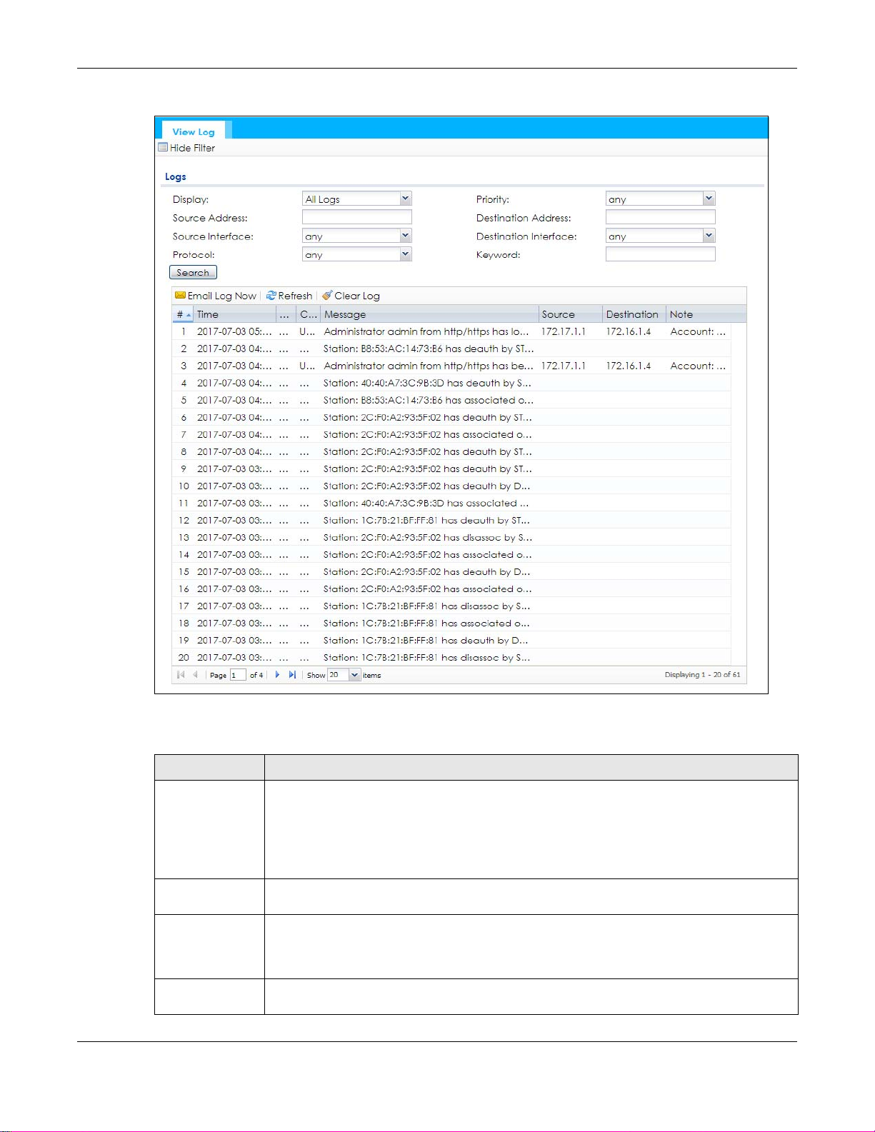
Figure 40 Monitor > Log > View Log
Chapter 5 Monitor
The following table describes the labels in this screen.
Table 33 Monitor > Log > View Log
LABEL DESCRIPTION
Show Filter / Hide
Filter
Display Select the category of log message(s) you want to view. You can also view All Logs at one
Priority This displays when you show the filter. Select the priority of log messages to display. The log
Source Address This displays when you show the filter. Type the source IP address of the incoming packet that
Click this button to show or hide the filter settings.
If the filter settings are hidden, the Display, Email Log Now, Refresh, and Clear Log fields are
available.
If the filter settings are shown, the Display, Priority, Source Address, Destination Address, Source
Interface, Destination Interface, Protocol, Keyword, and Search fields are available.
time, or you can view the Debug Log.
displays the log messages with this priority or higher. Choices are: any, emerg, alert, crit, error,
warn, notice, and info, from highest priority to lowest priority. This field is read-only if the
Category is Debug Log.
generated the log message. Do not include the port in this filter.
NWA / WAC Series User’s Guide
73

Chapter 5 Monitor
Table 33 Monitor > Log > View Log (continued)
LABEL DESCRIPTION
Destination
Address
Source Interface This displays when you show the filter. Select the source interface of the packet that generated
Destination
Interface
Protocol This displays when you show the filter. Select a service protocol whose log messages you would
Keyword This displays when you show the filter. Type a keyword to look for in the Message, Source,
Search This displays when you show the filter. Click this button to update the log using the current filter
Email Log Now Click this button to send log messages to the Active e-mail addresses specified in the Send Log
Refresh Click this to update the list of logs.
Clear Log Click this button to clear the whole log, regardless of what is currently displayed on the screen.
# This field is a sequential value, and it is not associated with a specific log message.
Time This field displays the time the log message was recorded.
Priority This field displays the priority of the log message. It has the same range of values as the Priority
Category This field displays the log that generated the log message. It is the same value used in the
Message This field displays the reason the log message was generated. The text “[count=x]”, where x is a
Source This field displays the source IP address and the port number in the event that generated the
Source Interface This field displays the source interface of the packet that generated the log message.
Destination This field displays the destination IP address and the port number of the event that generated
Destination
Interface
Protocol This field displays the service protocol in the event that generated the log message.
Note This field displays any additional information about the log message.
This displays when you show the filter. Type the IP address of the destination of the incoming
packet when the log message was generated. Do not include the port in this filter.
the log message.
This displays when you show the filter. Select the destination interface of the packet that
generated the log message.
like to see.
Destination and Note fields. If a match is found in any field, the log message is displayed. You
can use up to 63 alphanumeric characters and the underscore, as well as punctuation marks
()’ ,:;?! +-*/= #$% @ ; the period, double quotes, and brackets are not allowed.
settings.
To field on the Configuration > Log & Report > Log Settings screen.
field above.
Display and (other) Category fields.
number, appears at the end of the Message field if log consolidation is turned on and multiple
entries were aggregated to generate into this one.
log message.
the log message.
This field displays the destination interface of the packet that generated the log message.
The Web Configurator saves the filter settings if you leave the View Log screen and return to it later.
NWA / WAC Series User’s Guide
74
6.1 Overview
This chapter describes how you can configure the management IP address and VLAN settings of your
NWA/WAC.
The Internet Protocol (IP) address identifies a device on a network. Every networking device (including
computers, servers, routers, printers, etc.) needs an IP address to communicate across the network.
These networking devices are also known as hosts.
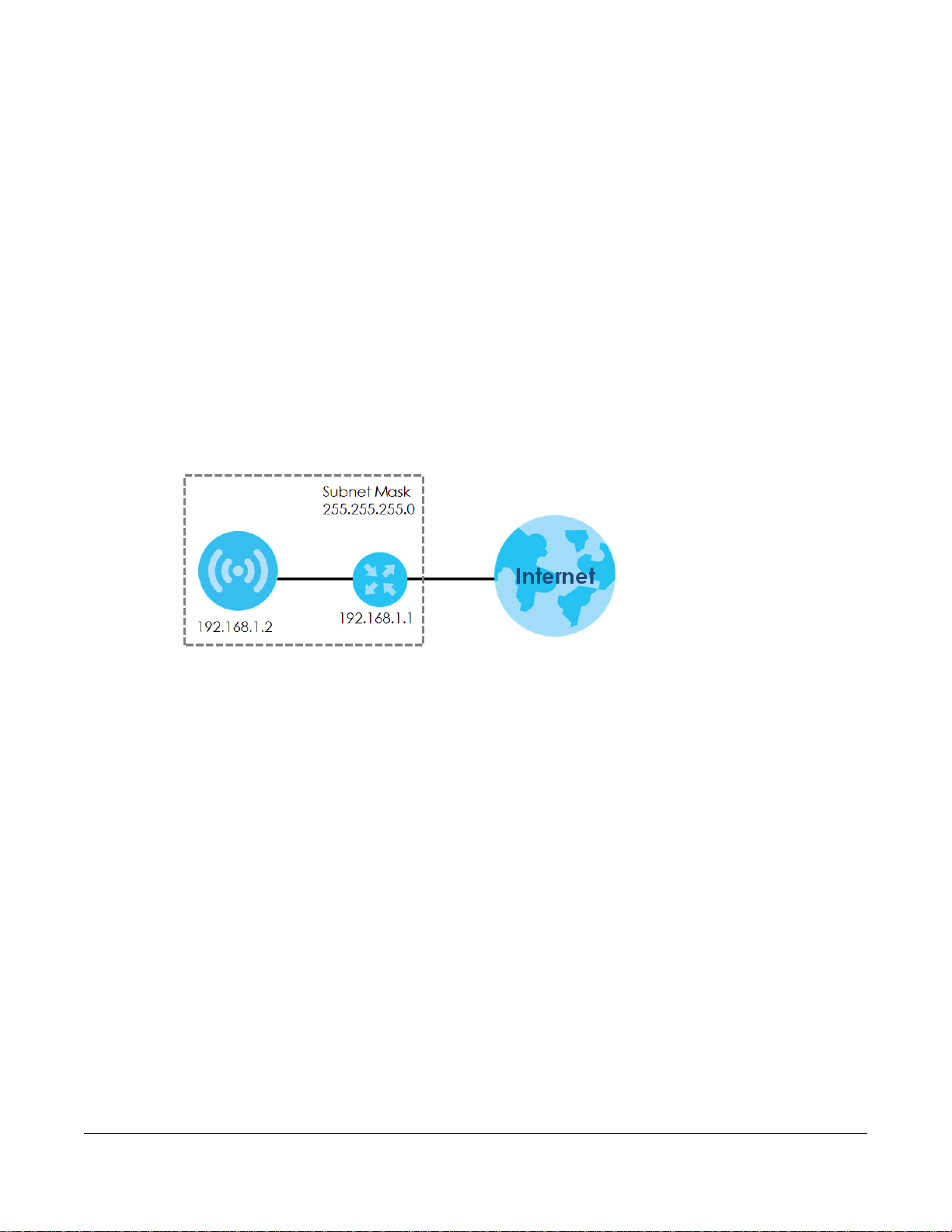
Figure 41 IP Setup
CHAPTER 6
Network
The figure above illustrates one possible setup of your NWA/WAC. The gateway IP address is 192.168.1.1
and the managed IP address of the NWA/WAC is 192.168.1.2 (default), but if the NWA/WAC is assigned
an IP address by a DHCP server, the default (192.168.1.2) will not be used. The gateway and the NWA/
WAC must belong in the same IP subnet to be able to communicate with each other.
6.1.1 Management Mode
This discusses using the NWA/WAC in management mode, which determines whether the NWA/WAC is
used in its standalone mode, or as part of a Control And Provisioning of Wireless Access Points (CAPWAP)
network.
About CAPWAP
The NWA/WAC supports CAPWAP. This is Zyxel’s implementation of the CAPWAP protocol (RFC 5415).
The CAPWAP data flow is protected by Datagram Transport Layer Security (DTLS).
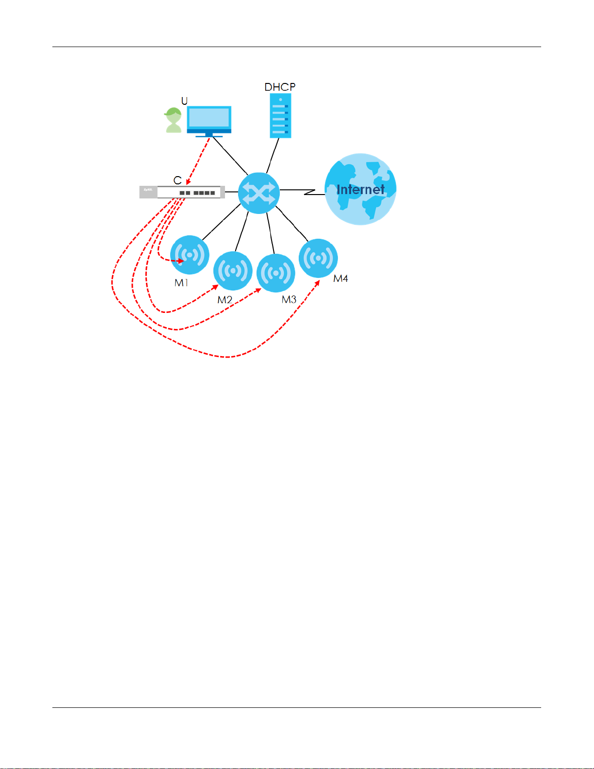
The following figure illustrates a CAPWAP wireless network. You (U) configure the AP controller (C), which
then automatically updates the configurations of the managed APs (M1 ~ M4).
NWA / WAC Series User’s Guide
75
Chapter 6 Network
Figure 42 CAPWAP Network Example
Note: The NWA/WAC can be a standalone AP (default), or a CAPWAP managed AP.
CAPWAP Discovery and Management
The link between CAPWAP-enabled access points proceeds as follows:
1 An AP in managed AP mode joins a wired network (receives a dynamic IP address).
2 The AP sends out a discovery request, looking for a CAPWAP AP controller.
3 If there is an AP controller on the network, it receives the discovery request. If the AP controller is in
Manual mode it adds the details of the AP to its Unmanaged Access Points list, and you decide which
available APs to manage. If the AP controller is in Always Accept mode, it automatically adds the AP to
its Managed Access Points list and provides the managed AP with default configuration information, as
well as securely transmitting the DTLS pre-shared key. The managed AP is ready for association with
wireless clients.
Managed AP Finds the Controller
A managed NWA/WAC can find the controller in one of the following ways:
• Manually specify the controller’s IP address in the Web Configurator’s AC (AP Controller) Discovery
screen.
• Get the controller’s IP address from a DHCP server with the controller’s IP address configured as
option 138.
• Get the controller’s IP address from a DNS server SRV (Service) record.
NWA / WAC Series User’s Guide
76
Chapter 6 Network
• Broadcasting to discover the controller within the broadcast domain.
Note: The AP controller needs to have a static IP address. If it is a DHCP client, set the DHCP
server to reserve an IP address for the AP controller.
CAPWAP and IP Subnets
By default, CAPWAP works only between devices with IP addresses in the same subnet.
However, you can configure CAPWAP to operate between devices with IP addresses in different
subnets by doing the following.
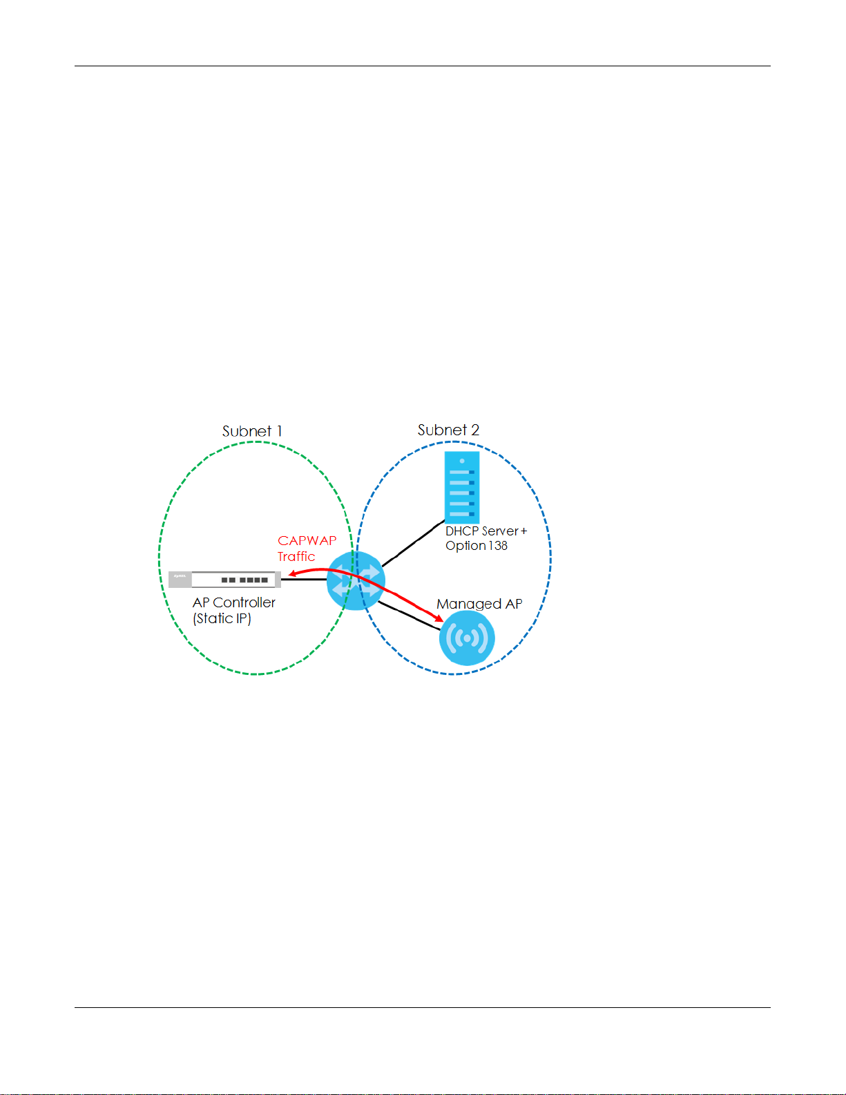
• Activate DHCP. Your network’s DHCP server must support option 138 defined in RFC 5415.
• Configure DHCP option 138 with the IP address of the CAPWAP AP controller on your network.
DHCP Option 138 allows the CAPWAP management request (from the AP in managed AP mode) to
reach the AP controller in a different subnet, as shown in the following figure.
Figure 43 CAPWAP and DHCP Option 138
Notes on CAPWAP
This section lists some additional features of Zyxel’s implementation of the CAPWAP protocol.
• When the AP controller uses its internal Remote Authentication Dial In User Service (RADIUS) server,
managed APs also use the AP controller’s authentication server to authenticate wireless clients.
• If a managed AP’s link to the AP controller is broken, the managed AP continues to use the wireless
settings with which it was last provided.
6.1.2 What You Can Do in this Chapter
• The IP Setting screen (Section 6.2 on page 78) configures the NWA/WAC’s LAN IP address.
• The VLAN screen (Section 6.3 on page 79) configures the NWA/WAC’s VLAN settings.
• The AC (AP Controller) Discovery screen (Section 6.3 on page 79) configures the NWA/WAC’s AP
Controller settings.
NWA / WAC Series User’s Guide
77
6.2 IP Setting
Use this screen to configure the IP address for your NWA/WAC. To access this screen, click Configuration
> Network > IP Setting.
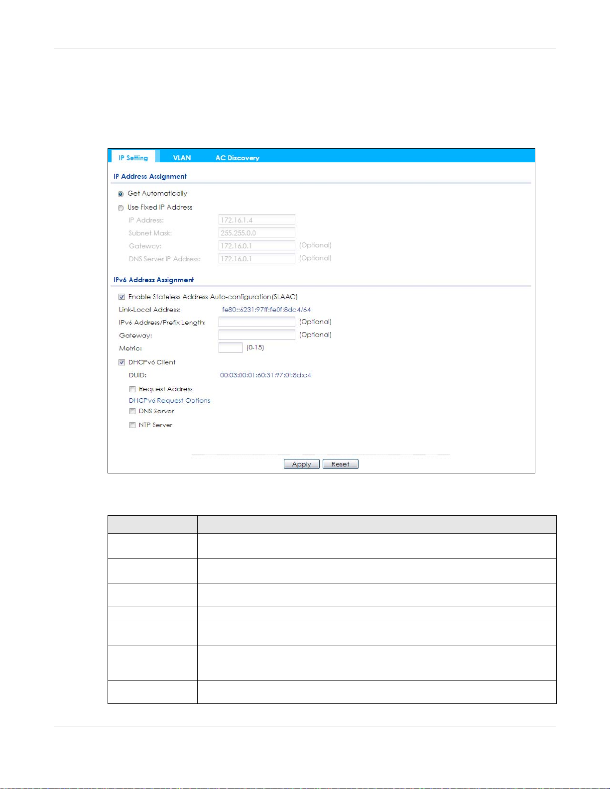
Figure 44 Configuration > Network > IP Setting
Chapter 6 Network
Each field is described in the following table.
Table 34 Configuration > Network > IP Setting
LABEL DESCRIPTION
IP Address
Assignment
Get
Automatically
Use Fixed IP
Address
IP Address Enter the IP address for this interface.
Subnet Mask Enter the subnet mask of this interface in dot decimal notation. The subnet mask indicates
Gateway Enter the IP address of the gateway. The NWA/WAC sends packets to the gateway when it
DNS Server IP
Address
Select this to make the interface a DHCP client and automatically get the IP address,
subnet mask, and gateway address from a DHCP server.
Select this if you want to specify the IP address, subnet mask, and gateway manually.
what part of the IP address is the same for all computers in the network.
does not know how to route the packet to its destination. The gateway should be on the
same network as the interface.
Enter the IP address of the DNS server.
NWA / WAC Series User’s Guide
78

Chapter 6 Network
Table 34 Configuration > Network > IP Setting (continued)
LABEL DESCRIPTION
IPv6 Address
Assignment
Enable Stateless
Address Autoconfiguration
(SLAAC)
Link-Local
Address
IPv6 Address/
Prefix Length
Gateway Enter the IPv6 address of the default outgoing gateway using colon (:) hexadecimal
Metric Enter the priority of the gateway (if any) on the LAN interface. The NWA/WAC decides
DHCPv6 Client Select this option to set the NWA/WAC to act as a DHCPv6 client.
DUID This field displays the DHCP Unique IDentifier (DUID) of the NWA/WAC, which is unique and
Request Address Select this option to get an IPv6 address from the DHCPv6 server.
DHCPv6 Request
Options
DNS Server Select this option to obtain the IP address of the DNS server.
NTP Server Select this option to obtain the IP address of the NTP server.
Apply Click Apply to save your changes back to the NWA/WAC.
Reset Click Reset to return the screen to its last-saved settings.
Select this to enable IPv6 stateless auto-configuration on the NWA/WAC. The NWA/WAC will
generate an IPv6 address itself from a prefix obtained from an IPv6 router in the network.
This displays the IPv6 link-local address and the network prefix that the NWA/WAC
generates itself for the LAN interface.
Enter the IPv6 address and the prefix length for the LAN interface if you want to use a static
IP address. This field is optional.
The prefix length indicates what the left-most part of the IP address is the same for all
computers in the network, that is, the network address.
notation.
which gateway to use based on this priority. The lower the number, the higher the priority. If
two or more gateways have the same priority, the NWA/WAC uses the one that was
configured first. Enter zero to set the metric to 1024 for IPv6.
used for identification purposes when the NWA/WAC is exchanging DHCPv6 messages with
others. See Appendix B on page 227 for more information.
Select this option to determine what additional information to get from the DHCPv6 server.
6.3 VLAN
This section discusses how to configure the NWA/WAC’s VLAN settings.
NWA / WAC Series User’s Guide
79
Chapter 6 Network
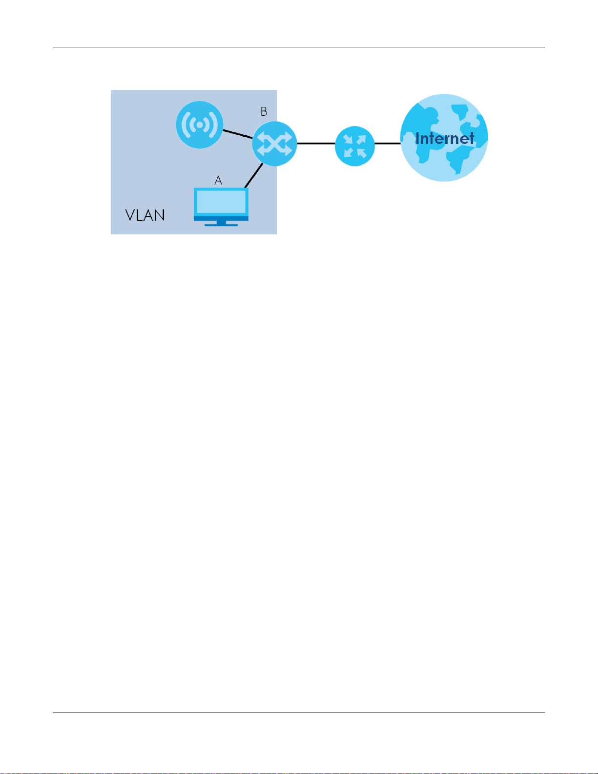
Figure 45 Management VLAN Setup
In the figure above, to access and manage the NWA/WAC from computer A, the NWA/WAC and
switch B’s ports to which computer A and the NWA/WAC are connected should be in the same VLAN.
A Virtual Local Area Network (VLAN) allows a physical network to be partitioned into multiple logical
networks. Devices on a logical network belong to one group. A device can belong to more than one
group. With VLAN, a device cannot directly talk to or hear from devices that are not in the same
group(s); the traffic must first go through a router.
VLAN also increases network performance by limiting broadcasts to a smaller and more manageable
logical broadcast domain. In traditional switched environments, all broadcast packets go to each and
every individual port. With VLAN, all broadcasts are confined to a specific broadcast domain.
IEEE 802.1Q Tag
The IEEE 802.1Q standard defines an explicit VLAN tag in the MAC header to identify the VLAN
membership of a frame across bridges. A VLAN tag includes the 12-bit VLAN ID and 3-bit user priority.
The VLAN ID associates a frame with a specific VLAN and provides the information that devices need to
process the frame across the network.
Use this screen to configure the VLAN settings for your NWA/WAC. To access this screen, click
Configuration > Network > VLAN.
The screen varies depending on whether the NWA/WAC has an extra Ethernet port (except the uplink
port).
NWA / WAC Series User’s Guide
80

Chapter 6 Network
Figure 46 Configuration > Network > VLAN (for NWA/WAC with multiple Ethernet ports)
Figure 47 Configuration > Network > VLAN (for NWA/WAC with one Ethernet port)
Each field is described in the following table.
Table 35 Configuration > Network > VLAN
LABEL DESCRIPTION
VLAN Settings
Management
VLAN ID
As Native VLAN Select this option to treat this VLAN ID as a VLAN created on the NWA/WAC and not one
LAN Setting
Port Setting
Edit Double-click an entry or select it and click Edit to open a screen where you can modify the
Activate/
Inactivate
# This is the index number of the port.
Enter a VLAN ID for the NWA/WAC.
assigned to it from outside the network.
entry’s settings. In some tables you can just click a table entry and edit it directly in the
table. For those types of tables small red triangles display for table entries with changes that
you have not yet applied.
To turn on an entry, select it and click Activate. To turn off an entry, select it and click
Inactivate.
NWA / WAC Series User’s Guide
81

Chapter 6 Network
Table 35 Configuration > Network > VLAN (continued)
LABEL DESCRIPTION
Status This field indicates whether the port is enabled (a yellow bulb) or not (a gray bulb).
Port This field displays the name of the port.
PVID This field displays the port number of the VLAN ID.
VLAN Configuration
Add Click this to create a new entry. For features where the entry’s position in the numbered list is
important (features where the NWA/WAC applies the table’s entries in order like the SSID for
example), you can select an entry and click Add to create a new entry after the selected
entry.
Edit Double-click an entry or select it and click Edit to open a screen where you can modify the
entry’s settings. In some tables you can just click a table entry and edit it directly in the
table. For those types of tables small red triangles display for table entries with changes that
you have not yet applied.
Remove To remove an entry, select it and click Remove. The NWA/WAC confirms you want to
remove it before doing so.
Activate/
Inactivate
# This is the index number of the VLAN ID
Status This field indicates whether the VLAN is enabled (a yellow bulb) or not (a gray bulb).
Name This field displays the name of each VLAN.
VID This field displays the VLAN ID.
Member This field displays the VLAN membership to which the port belongs.
Apply Click Apply to save your changes back to the NWA/WAC.
Reset Click Reset to return the screen to its last-saved settings.
To turn on an entry, select it and click Activate. To turn off an entry, select it and click
Inactivate.
6.4 AC (AP Controller) Discovery
This section discusses how to configure the NWA/WAC’s AC (AP Controller) Discovery settings. You can
have the NWA/WAC managed by an AP controller on your network. When you do this, the NWA/WAC
can be configured ONLY by the AP controller. See Section 6.1.1 on page 75 for more information on
management mode and AP Controller.
Note: The AC (AP Controller) Discovery settings are not available in all NWA/WACs. See
Section 1.1 on page 13 for more information.
If you want to return the NWA/WAC to standalone AP mode, you can do one of the two following
options:
• Press the Reset button.
• Check the AP controller for the NWA/WAC’s IP address and use FTP to upload the default
configuration file to the NWA/WAC. You can get the configuration file at conf/system-default.conf.
You must reboot the device after uploading the configuration file.
To access the Controller Discover screen, click Configuration > Network > AC Discovery.
NWA / WAC Series User’s Guide
82

Chapter 6 Network
Figure 48 Configuration > Network > AC Discovery
Each field is described in the following table.
Table 36 Configuration > Network > AC Discovery
LABEL DESCRIPTION
Discovery Setting
Auto Select this option to use DHCP option 138/DNS SRV record/Broadcast to get the AP
controller’s IP address. If the NWA/WAC and a Zyxel AP controller, such as the NXC2500
or NXC5500, are in the same subnet, it will be managed by the controller automatically.
Manual Select this option and enter the IP address of the AP controller manually. This is
necessary when the AP Controller is not in the same subnet and you want it to manage
the NWA/WAC.
Primary / Secondary
Static AC IP
Disable Select this to manage the NWA/WAC using its own web configurator, neither managing
Apply Click Apply to save the information entered in this screen.
Reset Click Reset to return the screen to its last-saved settings.
Specify the primary and secondary IP address of the AP controller to which the NWA/
WAC connects.
nor managed by other devices. Please note if an AP Controller is in the same subnet,
you will need to click Disable if you do not want the NWA/WAC to be managed.
If you select Auto or Manual, the AP controller uploads the firmware package for
managed AP mode to the NWA/WAC and you cannot log in as the web configurator is
disabled; you must manage the NWA/WAC through the AP controller on your network.
NWA / WAC Series User’s Guide
83

7.1 Overview
This chapter discusses how to configure the wireless network settings in your NWA/WAC.
The following figure provides an example of a wireless network.
Figure 49 Example of a Wireless Network
CHAPTER 7
Wireless
The wireless network is the part in the blue circle. In this wireless network, devices A and B are called
wireless clients. The wireless clients use the access point (AP) to interact with other devices (such as the
printer) or with the Internet. Your NWA/WAC is the AP.
7.1.1 What You Can Do in this Chapter
• The AP Management screen (Section 7.2 on page 85) manages the NWA/WAC’s general wireless
settings.
• The Rogue AP screen (Section 7.3 on page 88) allows you to assign APs either to the rogue AP list or
the friendly AP list.
• The Load Balancing screen (Section 7.4 on page 91) configures network traffic load balancing
between the APs and the NWA/WAC.
• The DCS screen (Section 7.5 on page 94) configures dynamic radio channel selection.
NWA / WAC Series User’s Guide
84

7.1.2 What You Need to Know
The following terms and concepts may help as you read this chapter.
Station / Wireless Client
A station or wireless client is any wireless-capable device that can connect to an AP using a wireless
signal.
Dynamic Channel Selection (DCS)
Dynamic Channel Selection (DCS) is a feature that allows an AP to automatically select the radio
channel upon which it broadcasts by scanning the area around it and determining what channels are
currently being used by other devices.
Load Balancing (Wireless)
Wireless load balancing is the process where you limit the number of connections allowed on an wireless
access point (AP) or you limit the amount of wireless traffic transmitted and received on it so the AP
does not become overloaded.
Chapter 7 Wireless
7.2 AP Management
Use this screen to manage the NWA/WAC’s general wireless settings. Click Configuration > Wireless > AP
Management to access this screen.
NWA / WAC Series User’s Guide
85

Chapter 7 Wireless
Figure 50 Configuration > Wireless > AP Management
Each field is described in the following table.
Table 37 Configuration > Wireless > AP Management
LABEL DESCRIPTION
Radio 1 Setting
Radio 1 Activate Select the check box to enable the NWA/WAC’s first (default) radio.
NWA / WAC Series User’s Guide
86

Chapter 7 Wireless
Table 37 Configuration > Wireless > AP Management (continued)
LABEL DESCRIPTION
Radio 1 OP Mode Select the operating mode for radio 1.
AP Mode means the radio can receive connections from wireless clients and pass their data
traffic through to the NWA/WAC to be managed (or subsequently passed on to an
upstream gateway for managing).
MON Mode means the radio monitors the broadcast area for other APs, then passes their
information on to the NWA/WAC where it can be determined if those APs are friendly or
rogue. If a radio is set to this mode it cannot receive connections from wireless clients.
Root AP means the radio acts as an AP and also supports the wireless connections with
other APs (in repeater mode) to form a WDS (Wireless Distribution System) to extend its
wireless network.
Repeater means the radio can establish a wireless connection with other APs (in either root
AP or repeater mode) to form a WDS.
Radio 1 Profile Select the radio profile the radio uses.
Note: You can only apply a 2.4G AP radio profile to radio 1. Otherwise, the first
radio will not be working.
Radio 1 WDS Profile This field is available only when the radio is in Root AP or Repeater mode.
Select the WDS profile the radio uses to connect to a root AP or repeater.
Uplink Selection
Mode
Max Output Power Enter the maximum output power (between 0 to 30 dBm) of the NWA/WAC in this field. If
This field is available only when the radio is in Repeater mode.
Select AUTO to have the NWA/WAC automatically use the settings in the applied WDS
profile to connect to a root AP or repeater.
Select Manual to have the NWA/WAC connect to the root AP or repeater with the MAC
address specified in the Radio 1 Uplink MAC Address field.
there is a high density of APs in an area, decrease the output power of the NWA/WAC to
reduce interference with other APs.
Note: Reducing the output power also reduces the NWA/WAC’s effective
broadcast radius.
MBSSID Settings
Edit Double-click an entry or select it and click Edit to open a screen where you can modify the
entry’s settings. In some tables you can just click a table entry and edit it directly in the
table. For those types of tables small red triangles display for table entries with changes that
you have not yet applied.
# This field shows the index number of the SSID
SSID Profile This field displays the SSID profile that is associated with the radio profile.
Radio 2 Setting
Radio 2 Activate This displays if the NWA/WAC has a second radio.
Select the check box to enable the NWA/WAC’s second radio.
NWA / WAC Series User’s Guide
87

Chapter 7 Wireless
Table 37 Configuration > Wireless > AP Management (continued)
LABEL DESCRIPTION
Radio 2 OP Mode This displays if the NWA/WAC has a second radio. Select the operating mode for radio 2.
AP Mode means the radio can receive connections from wireless clients and pass their data
traffic through to the NWA/WAC to be managed (or subsequently passed on to an
upstream gateway for managing).
MON Mode means the radio monitors the broadcast area for other APs, then passes their
information on to the NWA/WAC where it can be determined if those APs are friendly or
rogue. If a radio is set to this mode it cannot receive connections from wireless clients.
Root AP means the radio acts as an AP and also supports the wireless connections with
other APs (in repeater mode) to form a WDS to extend its wireless network.
Repeater means the radio can establish a wireless connection with other APs (in either root
AP or repeater mode) to form a WDS.
Radio 2 Profile This displays if the NWA/WAC has a second radio. Select the radio profile the radio uses.
Note: You can only apply a 5G AP radio profile to radio 2. Otherwise, the second
radio will not be working.
Radio 2 WDS Profile This field is available only when the radio is in Root AP or Repeater mode.
Select the WDS profile the radio uses to connect to a root AP or repeater.
Uplink Selection
Mode
This field is available only when the radio is in Repeater mode.
Select AUTO to have the NWA/WAC automatically use the settings in the applied WDS
profile to connect to a root AP or repeater.
Max Output Power Enter the maximum output power (between 0 to 30 dBm) of the NWA/WAC in this field. If
MBSSID Settings
Edit Double-click an entry or select it and click Edit to open a screen where you can modify the
# This field shows the index number of the SSID
SSID Profile This field shows the SSID profile that is associated with the radio profile.
Apply Click Apply to save your changes back to the NWA/WAC.
Reset Click Reset to return the screen to its last-saved settings.
7.3 Rogue AP
Use this screen to assign APs either to the rogue AP list or the friendly AP list. A rogue AP is a wireless
access point operating in a network’s coverage area that is not under the control of the network
administrator, and which can potentially open up holes in a network’s security.
Select Manual to have the NWA/WAC connect to the root AP or repeater with tbe MAC
address specified in the Radio 2 Uplink MAC Address field.
there is a high density of APs in an area, decrease the output power of the NWA/WAC to
reduce interference with other APs.
Note: Reducing the output power also reduces the NWA/WAC’s effective
broadcast radius.
entry’s settings. In some tables you can just click a table entry and edit it directly in the
table. For those types of tables small red triangles display for table entries with changes that
you have not yet applied.
Click Configuration > Wireless > Rogue AP to access this screen.
NWA / WAC Series User’s Guide
88

Chapter 7 Wireless
Figure 51 Configuration > Wireless > Rogue AP (for NWA/WAC that supports Monitor mode)
Figure 52 Configuration > Wireless > Rogue AP (for NWA/WAC that doesn’t support Monitor mode)
NWA / WAC Series User’s Guide
89

Chapter 7 Wireless
Each field is described in the following table.
Table 38 Configuration > Wireless > Rogue AP
LABEL DESCRIPTION
Rogue AP Detection
Setting
Enable Rogue AP
Detection
Suspected Rogue AP
Classification Rule
Add Click this to add an SSID Keyword.
Edit Select an SSID Keyword and click this button to modify it.
Remove Select an existing SSID keyword and click this button to delete it.
# This is the SSID Keyword’s index number in this list.
SSID Keyword This field displays the SSID Keyword.
Rogue/Friendly AP List
Add Click this button to add an AP to the list and assign it either friendly or rogue status.
Edit Select an AP in the list to edit and reassign its status.
Remove Select an AP in the list to remove.
# This field is a sequential value, and it is not associated with any interface.
Role This field indicates whether the selected AP is a rogue-ap or a friendly-ap. To change
MAC Address This field indicates the AP’s radio MAC address.
Description This field displays the AP’s description. You can modify this by clicking the Edit button.
Rogue/Friendly AP List
Importing/Exporting
File Path / Browse /
Importing
Select this option to detect Rogue APs in the network.
Click the check boxes (Weak Security (Open, WEP, WPA-PSK), Hidden SSID, SSID
Keyword) of the characteristics an AP should have for the NWA/WAC to rule it as a
Rogue AP.
the AP’s role, click the Edit button.
These controls allow you to export the current list of rogue and friendly APs or import
existing lists.
Enter the file name and path of the list you want to import or click the Browse button
to locate it. Once the File Path field has been populated, click Importing to bring the
list into the NWA/WAC.
You need to wait a while for the importing process to finish.
Exporting Click this button to export the current list of either rogue APs or friendly APS.
Apply Click Apply to save your changes back to the NWA/WAC.
Reset Click Reset to return the screen to its last-saved settings.
7.3.1 Add/Edit Rogue/Friendly List
Click Add or select an AP and click the Edit button in the Configuration > Wireless > Rogue AP table to
display this screen.
NWA / WAC Series User’s Guide
90

Chapter 7 Wireless
Figure 53 Configuration > Wireless > Rogue AP > Add/Edit Rogue/Friendly AP List
Each field is described in the following table.
Table 39 Configuration > Wireless > Rogue AP > Add/Edit Rogue/Friendly AP List
LABEL DESCRIPTION
MAC Enter the MAC address of the AP you want to add to the list. A MAC address is a unique
Description Enter up to 60 characters for the AP’s description. Spaces and underscores are allowed.
Role Select either Rogue AP or Friendly AP for the AP’s role.
OK Click OK to save your changes back to the NWA/WAC.
Cancel Click Cancel to close the window with changes unsaved.
hardware identifier in the following hexadecimal format: xx:xx:xx:xx:xx:xx where xx is a
hexadecimal number separated by colons.
7.4 Load Balancing
Use this screen to configure wireless network traffic load balancing between the APs on your network.
Click Configuration > Wireless > Load Balancing to access this screen.
Figure 54 Configuration > Wireless > Load Balancing
NWA / WAC Series User’s Guide
91

Chapter 7 Wireless
Each field is described in the following table.
Table 40 Configuration > Wireless > Load Balancing
LABEL DESCRIPTION
Enable Load
Balancing
Mode Select a mode by which load balancing is carried out.
Max Station
Number
Traffic Level Select the threshold traffic level at which the NWA/WAC begins load balancing its
Disassociate
station when
overloaded
Select this to enable load balancing on the NWA/WAC.
Use this section to configure wireless network traffic load balancing between the managed
APs in this group.
Select By Station Number to balance network traffic based on the number of specified
stations connected to the NWA/WAC.
Select By Traffic Level to balance network traffic based on the volume generated by the
stations connected to the NWA/WAC.
Select By Smart Classroom to balance network traffic based on the number of specified
stations connected to the NWA/WAC. The NWA/WAC ignores association request and
authentication request packets from any new station when the maximum number of
stations is reached.
If you select By Station Number or By Traffic Level, once the threshold is crossed (either the
maximum station numbers or with network traffic), the NWA/WAC delays association
request and authentication request packets from any new station that attempts to make a
connection. This allows the station to automatically attempt to connect to another, less
burdened AP if one is available.
Enter the threshold number of stations at which the NWA/WAC begins load balancing its
connections.
connections (Low, Medium, High).
The maximum bandwidth allowed for each level is:
• Low - 11 Mbps,
• Medium - 23 Mbps
• High - 35M bps
This function is enabled by default and the disassociation priority is always Signal Strength
when you set Mode to By Smart Classroom.
Select this option to disassociate wireless clients connected to the AP when it becomes
overloaded. If you do not enable this option, then the AP simply delays the connection until
it can afford the bandwidth it requires, or it transfers the connection to another AP within its
broadcast radius.
The disassociation priority is determined automatically by the NWA/WAC and is as follows:
• Idle Timeout - Devices that have been idle the longest will be kicked first. If none of the
connected devices are idle, then the priority shifts to Signal Strength.
• Signal Strength - Devices with the weakest signal strength will be kicked first.
Note: If you enable this function, you should ensure that there are multiple APs
within the broadcast radius that can accept any rejected or kicked
wireless clients; otherwise, a wireless client attempting to connect to an
overloaded AP will be disassociated permanently and never be allowed to
connect.
Apply Click Apply to save your changes back to the NWA/WAC.
Reset Click Reset to return the screen to its last-saved settings.
NWA / WAC Series User’s Guide
92

Chapter 7 Wireless
7.4.1 Disassociating and Delaying Connections
When your AP becomes overloaded, there are two basic responses it can take. The first one is to
“delay” a client connection. This means that the AP withholds the connection until the data transfer
throughput is lowered or the client connection is picked up by another AP. If the client is picked up by
another AP then the original AP cannot resume the connection.
For example, here the AP has a balanced bandwidth allotment of 6 Mbps. If laptop R connects and it
pushes the AP over its allotment, say to 7 Mbps, then the AP delays the red laptop’s connection until it
can afford the bandwidth or the laptop is picked up by a different AP with bandwidth to spare.
Figure 55 Delaying a Connection
The second response your AP can take is to kick the connections that are pushing it over its balanced
bandwidth allotment.
Figure 56 Kicking a Connection
NWA / WAC Series User’s Guide
93

Connections are kicked based on either idle timeout or signal strength. The NWA/WAC first looks to see
which devices have been idle the longest, then starts kicking them in order of highest idle time. If no
connections are idle, the next criteria the NWA/WAC analyzes is signal strength. Devices with the
weakest signal strength are kicked first.
7.5 DCS
Use this screen to configure dynamic radio channel selection. Click Configuration > Wireless > DCS to
access this screen.
Figure 57 Configuration > Wireless > DCS
Chapter 7 Wireless
Each field is described in the following table.
Table 41 Configuration > Wireless > DCS
LABEL DESCRIPTION
Select Now Click this to have the NWA/WAC scan for and select an available channel immediately.
Apply Click Apply to save your changes back to the NWA/WAC.
Reset Click Reset to return the screen to its last-saved settings.
7.6 Technical Reference
The following section contains additional technical information about the features described in this
chapter.
Dynamic Channel Selection
When numerous APs broadcast within a given area, they introduce the possibility of heightened radio
interference, especially if some or all of them are broadcasting on the same radio channel. If the
interference becomes too great, then the network administrator must open his AP configuration options
and manually change the channel to one that no other AP is using (or at least a channel that has a
lower level of interference) in order to give the connected stations a minimum degree of interference.
Dynamic channel selection frees the network administrator from this task by letting the AP do it
automatically. The AP can scan the area around it looking for the channel with the least amount of
interference.
In the 2.4 GHz spectrum, each channel from 1 to 13 is broken up into discrete 22 MHz segments that are
spaced 5 MHz apart. Channel 1 is centered on 2.412 GHz while channel 13 is centered on 2.472 GHz.
NWA / WAC Series User’s Guide
94

Chapter 7 Wireless
Figure 58 An Example Three-Channel Deployment
Three channels are situated in such a way as to create almost no interference with one another if used
exclusively: 1, 6 and 11. When an AP broadcasts on any of these three channels, it should not interfere
with neighboring APs as long as they are also limited to same trio.
Figure 59 An Example Four-Channel Deployment
However, some regions require the use of other channels and often use a safety scheme with the
following four channels: 1, 4, 7 and 11. While they are situated sufficiently close to both each other and
the three so-called “safe” channels (1,6 and 11) that interference becomes inevitable, the severity of it is
dependent upon other factors: proximity to the affected AP, signal strength, activity, and so on.
Finally, there is an alternative four channel scheme for ETSI, consisting of channels 1, 5, 9, 13. This offers
significantly less overlap that the other one.
Figure 60 An Alternative Four-Channel Deployment
Load Balancing
Because there is a hard upper limit on an AP’s wireless bandwidth, load balancing can be crucial in
areas crowded with wireless users. Rather than let every user connect and subsequently dilute the
NWA / WAC Series User’s Guide
95

Chapter 7 Wireless
available bandwidth to the point where each connecting device receives a meager trickle, the load
balanced AP instead limits the incoming connections as a means to maintain bandwidth integrity.
There are three kinds of wireless load balancing available on the NWA/WAC:
Load balancing by station number limits the number of devices allowed to connect to your AP. If you
know exactly how many stations you want to let connect, choose this option.
For example, if your company’s graphic design team has their own AP and they have 10 computers,
you can load balance for 10. Later, if someone from the sales department visits the graphic design
team’s offices for a meeting and he tries to access the network, his computer’s connection is delayed,
giving it the opportunity to connect to a different, neighboring AP. If he still connects to the AP
regardless of the delay, then the AP may boot other people who are already connected in order to
associate with the new connection.
Load balancing by smart classroom also limits the number of devices allowed to connect to your AP.
But any new connections will be just rejected when the AP is overloaded.
Load balancing by traffic level limits the number of connections to the AP based on maximum
bandwidth available. If you are uncertain as to the exact number of wireless connections you will have
then choose this option. By setting a maximum bandwidth cap, you allow any number of devices to
connect as long as their total bandwidth usage does not exceed the configured bandwidth cap
associated with this setting. Once the cap is hit, any new connections are rejected or delayed provided
that there are other APs in range.
Imagine a coffee shop in a crowded business district that offers free wireless connectivity to its
customers. The coffee shop owner can’t possibly know how many connections his AP will have at any
given moment. As such, he decides to put a limit on the bandwidth that is available to his customers but
not on the actual number of connections he allows. This means anyone can connect to his wireless
network as long as the AP has the bandwidth to spare. If too many people connect and the AP hits its
bandwidth cap then all new connections must basically wait for their turn or get shunted to the nearest
identical AP.
NWA / WAC Series User’s Guide
96

8.1 Overview
Use this screen to configure the Bluetooth advertising settings for the NWA/WAC that supports Bluetooth
Low Energy (BLE). Bluetooth Low Energy, which is also known as Bluetooth Smart, transmits less data over
a shorter distance and consumes less power than classic Bluetooth.
8.1.1 What You Need To Know
iBeacon is Apple’s communication protocol on top of Bluetooth Low Energy wireless technology.
Beacons (Bluetooth radio transmitters) or BLE enabled devices broadcast packets to every device
around it to announce their presence. Advertising packets contain their iBeacon ID which mainly
consists of the UUID, major number, minor number and TX (transmit) power. The ID is used to distinguish
beacons in your network.
CHAPTER 8
Bluetooth
The universally unique identifier (UUID) is a 128-bit (16-byte) number which can be used to identify a
service, a device, a manufacturer or an owner. The 2-byte major number is to identify and distinguish a
group, and the 2-byte minor number is to identify and distinguish an individual.
For example, you can set all the beacons in one network to share the same UUID, the beacons in a
particular room to use the same major number, and each beacon in the room can have its own minor
number.
NETWORK A
ROOM X ROOM Y
BEACON 1 BEACON 2 BEACON 3
UUID EBAECFAF-DFE0-4039-BE5A-F030EED4303C
Major 10 10 20
Minor 121
8.2 Bluetooth Advertising Settings
The NWA/WAC communicates with another BLE enabled device using advertisements. Use this screen
to configure the beacon ID(s) to be included in the advertising packet. You can have up to five
combinations of the UUID, Major and Minor parameters.
To access this screen, click Configuration > Bluetooth > Advertising Settings.
NWA / WAC Series User’s Guide
97

Chapter 8 Bluetooth
Figure 61 Configuration > Bluetooth > Advertising Settings
The following table describes the labels in this screen.
Table 42 Configuration > Bluetooth > Advertising Settings
LABEL DESCRIPTION
Edit Click this to edit the selected entry.
Activate To turn on an entry, select it and click Activate.
Inactivate To turn off an entry, select it and click Inactivate.
# This field is a sequential value, and it is not associated with a specific entry.
Status This field shows whether or not the entry is activated.
A yellow bulb signifies that this rule is active. A gray bulb signifies that this rule is not active.
UUID This field indicates the UUID to be included in the Bluetooth advertising packets.
Major This field indicates the major number to be included in the Bluetooth advertising packets.
Minor This field indicates the minor number to be included in the Bluetooth advertising packets.
8.2.1 Edit Advertising Settings
Select an entry in the Configuration > Bluetooth > Advertising Settings screen and click the Edit icon to
open the Edit Advertising screen. Use this screen to configure the beacon ID in the Bluetooth advertising
packets.
Figure 62 Configuration > Bluetooth > Advertising Settings > Edit
NWA / WAC Series User’s Guide
98

Chapter 8 Bluetooth
The following table describes the labels in this screen.
Table 43 Configuration > Bluetooth > Advertising Settings > Edit
LABEL DESCRIPTION
Activate Select this option to enable the advertising settings.
UUID To specify a UUID of the NWA/WAC’s beacon ID, enter 32 hexadecimal digits in the range of
Generate new
UUID
Major Enter an integer from 0 to 65535 as the major value to identify the beacon.
Minor Enter an integer from 0 to 65535 as the minor value to identify the beacon.
OK
Cancel Click Cancel to exit this screen without saving your changes.
“A-F”, “a-f” and “0-9”, split into five groups separated by hyphens (-). The UUID format is as
follows: xxxxxxxx-xxxx-xxxx-xxxx-xxxxxxxxxxxx (8-4-4-4-12)
Click this button to have the NWA/WAC generate a UUID automatically.
Click OK to save your changes back to the NWA/WAC.
NWA / WAC Series User’s Guide
99

9.1 Overview
This chapter describes how to set up user accounts and user settings for the NWA/WAC.
9.1.1 What You Can Do in this Chapter
• The User screen (see Section 9.2 on page 101) provides a summary of all user accounts.
•The Setting screen (see Section 9.3 on page 103) controls default settings, login settings, lockout
settings, and other user settings for the NWA/WAC.
9.1.2 What You Need To Know
The following terms and concepts may help as you read this chapter.
CHAPTER 9
User
User Account
A user account defines the privileges of a user logged into the NWA/WAC. User accounts are used in
controlling access to configuration and services in the NWA/WAC.
User Types
These are the types of user accounts the NWA/WAC uses.
Table 44 Types of User Accounts
TYPE ABILITIES LOGIN METHOD(S)
Admin Users
admin Change NWA/WAC configuration (web, CLI) WWW, TELNET, SSH, FTP
limited-admin Look at NWA/WAC configuration (web, CLI)
Perform basic diagnostics (CLI)
Access Users
user Used for the embedded RADIUS server and
SNMPv3 user access
Browse user-mode commands (CLI)
Note: The default admin account is always authenticated locally, regardless of the
authentication method setting.
WWW, TELNET, SSH
NWA / WAC Series User’s Guide
100

9.2 User Summary
The User screen provides a summary of all user accounts. To access this screen click Configuration >
Object > User.
Figure 63 Configuration > Object > User
The following table describes the labels in this screen.
Table 45 Configuration > Object > User
LABEL DESCRIPTION
Add Click this to create a new entry.
Edit Double-click an entry or select it and click Edit to open a screen where you can modify the
entry’s settings.
Remove To remove an entry, select it and click Remove. The NWA/WAC confirms you want to remove
it before doing so.
Object Reference Select an entry and click Object Reference to open a screen that shows which settings use
the entry.
# This field is a sequential value, and it is not associated with a specific user.
User Name This field displays the user name of each user.
User Type This field displays type of user this account was configured as.
Chapter 9 User
• admin - this user can look at and change the configuration of the NWA/WAC
• limited-admin - this user can look at the configuration of the NWA/WAC but not to
• user - this user has access to the NWA/WAC’s services but cannot look at the
Description This field displays the description for each user.
9.2.1 Add/Edit User
The User Add/Edit screen allows you to create a new user account or edit an existing one.
9.2.1.1 Rules for User Names
Enter a user name from 1 to 31 characters.
The user name can only contain the following characters:
• Alphanumeric A-z 0-9 (there is no unicode support)
• _ [underscores]
change it
configuration
NWA / WAC Series User’s Guide
101

Chapter 9 User
• - [dashes]
The first character must be alphabetical (A-Z a-z), an underscore (_), or a dash (-). Other limitations on
user names are:
• User names are case-sensitive. If you enter a user 'bob' but use 'BOB' when connecting via CIFS or FTP,
it will use the account settings used for 'BOB' not ‘bob’.
• User names have to be different than user group names.
• Here are the reserved user names:
•adm •admin •any •bin •daemon
•debug •devicehaecived•ftp •games •halt
•ldap-users •lp •mail •news •nobody
• operator • radius-users • root • shutdown • sshd
• sync • uucp • zyxel
To access this screen, go to the User screen, and click Add or Edit.
Figure 64 Configuration > Object > User > Add/Edit A User
The following table describes the labels in this screen.
Table 46 Configuration > User > User > Add/Edit A User
LABEL DESCRIPTION
User Name Type the user name for this user account. You may use 1-31 alphanumeric characters,
User Type Select what type of user this is. Choices are:
Password Enter the password of this user account. It can consist of 4 - 63 alphanumeric characters.
Retype Re-enter the password to make sure you have entered it correctly.
Description Enter the description of each user, if any. You can use up to 60 printable ASCII characters.
underscores(
sensitive. User names have to be different than user group names, and some words are
reserved.
• admin - this user can look at and change the configuration of the NWA/WAC
• limited-admin - this user can look at the configuration of the NWA/WAC but not to
change it
• user - this is used for embedded RADIUS server and SNMPv3 user access
Default descriptions are provided.
_), or dashes (-), but the first character cannot be a number. This value is case-
NWA / WAC Series User’s Guide
102

Chapter 9 User
Table 46 Configuration > User > User > Add/Edit A User (continued)
LABEL DESCRIPTION
Authentication
Timeout Settings
Lease Time This field is not available if the user type is user.
Reauthentication
Time
OK Click OK to save your changes back to the NWA/WAC.
Cancel Click Cancel to exit this screen without saving your changes.
This field is not available if the user type is user.
If you want to set authentication timeout to a value other than the default settings, select
Use Manual Settings then fill your preferred values in the fields that follow.
Enter the number of minutes this user has to renew the current session before the user is
logged out. You can specify 1 to 1440 minutes. You can enter 0 to make the number of
minutes unlimited. Admin users renew the session every time the main screen refreshes in the
Web Configurator.
This field is not available if the user type is user.
Type the number of minutes this user can be logged into the NWA/WAC in one session
before the user has to log in again. You can specify 1 to 1440 minutes. You can enter 0 to
make the number of minutes unlimited. Unlike Lease Time, the user has no opportunity to
renew the session without logging out.
9.3 Setting
This screen controls default settings, login settings, lockout settings, and other user settings for the NWA/
WAC.
To access this screen, login to the Web Configurator, and click Configuration > Object > User > Setting.
NWA / WAC Series User’s Guide
103

Chapter 9 User
Figure 65 Configuration > Object > User > Setting
The following table describes the labels in this screen.
Table 47 Configuration > Object > User > Setting
LABEL DESCRIPTION
User Default Setting
Default Authentication
Timeout Settings
Edit Double-click an entry or select it and click Edit to open a screen where you can
# This field is a sequential value, and it is not associated with a specific entry.
User Type These are the kinds of user account the NWA/WAC supports.
Lease Time This is the default lease time in minutes for each type of user account. It defines the
Reauthentication Time This is the default reauthentication time in minutes for each type of user account. It
User Logon Settings
These authentication timeout settings are used by default when you create a new
user account. They also control the settings for any existing user accounts that are
set to use the default settings. You can still manually configure any user account’s
authentication timeout settings.
modify the entry’s settings.
• admin - this user can look at and change the configuration of the NWA/WAC
• limited-admin - this user can look at the configuration of the NWA/WAC but not
to change it
• user - this is used for embedded RADIUS server and SNMPv3 user access
number of minutes the user has to renew the current session before the user is
logged out.
Admin users renew the session every time the main screen refreshes in the Web
Configurator.
defines the number of minutes the user can be logged into the NWA/WAC in one
session before having to log in again. Unlike Lease Time, the user has no opportunity
to renew the session without logging out.
NWA / WAC Series User’s Guide
104

Chapter 9 User
Table 47 Configuration > Object > User > Setting (continued)
LABEL DESCRIPTION
Limit the number of
simultaneous logons for
administration account
Maximum number per
administration account
User Lockout Settings
Enable logon retry limit Select this check box to set a limit on the number of times each user can login
Maximum retry count This field is effective when Enable logon retry limit is checked. Type the maximum
Lockout period This field is effective when Enable logon retry limit is checked. Type the number of
Apply Click Apply to save the changes.
Reset Click Reset to return the screen to its last-saved settings.
Select this check box if you want to set a limit on the number of simultaneous logins
by admin users. If you do not select this, admin users can login as many times as they
want at the same time using the same or different IP addresses.
This field is effective when Limit ... for administration account is checked. Type the
maximum number of simultaneous logins by each admin user.
unsuccessfully (for example, wrong password) before the IP address is locked out for
a specified amount of time.
number of times each user can login unsuccessfully before the IP address is locked
out for the specified lockout period. The number must be between 1 and 99.
minutes the user must wait to try to login again, if logon retry limit is enabled and the
maximum retry count is reached. This number must be between 1 and 65,535 (about
45.5 days).
9.3.1 Edit User Authentication Timeout Settings
This screen allows you to set the default authentication timeout settings for the selected type of user
account. These default authentication timeout settings also control the settings for any existing user
accounts that are set to use the default settings. You can still manually configure any user account’s
authentication timeout settings.
To access this screen, go to the Configuration > Object > User > Setting screen, select one of the Default
Authentication Timeout Settings entry and click the Edit icon.
Figure 66 User > Setting > Edit User Authentication Timeout Settings
NWA / WAC Series User’s Guide
105

Chapter 9 User
The following table describes the labels in this screen.
Table 48 User > Setting > Edit User Authentication Timeout Settings
LABEL DESCRIPTION
User Type This read-only field identifies the type of user account for which you are configuring the
Lease Time Enter the number of minutes this type of user account has to renew the current session
Reauthentication
Time
OK Click OK to save your changes back to the NWA/WAC.
Cancel Click Cancel to exit this screen without saving your changes.
default settings.
• admin - this user can look at and change the configuration of the NWA/WAC.
• limited-admin - this user can look at the configuration of the NWA/WAC but not to
change it.
before the user is logged out. You can specify 1 to 1440 minutes. You can enter 0 to make
the number of minutes unlimited.
Admin users renew the session every time the main screen refreshes in the Web Configurator.
Access users can renew the session by clicking the Renew button on their screen. If you allow
access users to renew time automatically, the users can select this check box on their screen
as well. In this case, the session is automatically renewed before the lease time expires.
Type the number of minutes this type of user account can be logged into the NWA/WAC in
one session before the user has to log in again. You can specify 1 to 1440 minutes. You can
enter 0 to make the number of minutes unlimited. Unlike Lease Time, the user has no
opportunity to renew the session without logging out.
NWA / WAC Series User’s Guide
106

10.1 Overview
This chapter shows you how to configure preset profiles for the NWA/WAC.
10.1.1 What You Can Do in this Chapter
• The Radio screen (Section 10.2 on page 108) creates radio configurations that can be used by the
APs.
• The SSID screen (Section 10.3 on page 114) configures three different types of profiles for your
networked APs.
10.1.2 What You Need To Know
CHAPTER 10
AP Profile
The following terms and concepts may help as you read this chapter.
Wireless Profiles
At the heart of all wireless AP configurations on the NWA/WAC are profiles. A profile represents a group
of saved settings that you can use across any number of connected APs. You can set up the following
wireless profile types:
• Radio - This profile type defines the properties of an AP’s radio transmitter. You can have a maximum
of 32 radio profiles on the NWA/WAC.
• SSID - This profile type defines the properties of a single wireless network signal broadcast by an AP.
Each radio on a single AP can broadcast up to 8 SSIDs. You can have a maximum of 32 SSID profiles
on the NWA/WAC.
• Security - This profile type defines the security settings used by a single SSID. It controls the encryption
method required for a wireless client to associate itself with the SSID. You can have a maximum of 32
security profiles on the NWA/WAC.
• MAC Filtering - This profile provides an additional layer of security for an SSID, allowing you to block
access or allow access to that SSID based on wireless client MAC addresses. If a client’s MAC address
is on the list, then it is either allowed or denied, depending on how you set up the MAC Filter profile.
You can have a maximum of 32 MAC filtering profiles on the NWA/WAC.
• Layer-2 Isolation - This profile defines the MAC addresses of the devices that you want to allow the
associated wireless clients to have access to when layer-2 isolation is enabled.
SSID
The SSID (Service Set IDentifier) is the name that identifies the Service Set with which a wireless station is
associated. Wireless stations associating to the access point (AP) must have the same SSID. In other
words, it is the name of the wireless network that clients use to connect to it.
NWA / WAC Series User’s Guide
107

WEP
WEP (Wired Equivalent Privacy) encryption scrambles all data packets transmitted between the AP and
the wireless stations associated with it in order to keep network communications private. Both the
wireless stations and the access points must use the same WEP key for data encryption and decryption.
WPA2
WPA2 (IEEE 802.11i) is a wireless security standard that defines stronger encryption, authentication and
key management than WPA. Key differences between WPA2 and WEP are improved data encryption
and user authentication.
IEEE 802.1x
The IEEE 802.1x standard outlines enhanced security methods for both the authentication of wireless
stations and encryption key management. Authentication is done using an external RADIUS server.
10.2 Radio
Chapter 10 AP Profile
This screen allows you to create radio profiles for the NWA/WAC. A radio profile is a list of settings that an
NWA/WAC can use to configure its radio transmitter(s). To access this screen click Configuration >
Object > AP Profile.
Note: You can have a maximum of 32 radio profiles on the NWA/WAC.
Figure 67 Configuration > Object > AP Profile > Radio
The following table describes the labels in this screen.
Table 49 Configuration > Object > AP Profile > Radio
LABEL DESCRIPTION
Add Click this to add a new radio profile.
Edit Click this to edit the selected radio profile.
Remove Click this to remove the selected radio profile.
Activate To turn on an entry, select it and click Activate.
NWA / WAC Series User’s Guide
108

Table 49 Configuration > Object > AP Profile > Radio (continued)
LABEL DESCRIPTION
Inactivate To turn off an entry, select it and click Inactivate.
Object
Reference
# This field is a sequential value, and it is not associated with a specific user.
Status This field shows whether or not the entry is activated.
Profile Name This field indicates the name assigned to the radio profile.
Frequency Band This field indicates the frequency band which this radio profile is configured to use.
Apply Click Apply to save your changes back to the NWA/WAC.
Reset Click Reset to return the screen to its last-saved settings.
Click this to view which other objects are linked to the selected radio profile.
A yellow bulb signifies that this rule is active. A gray bulb signifies that this rule is not active.
10.2.1 Add/Edit Radio Profile
This screen allows you to create a new radio profile or edit an existing one. To access this screen, click
the Add button or select a radio profile from the list and click the Edit button.
Chapter 10 AP Profile
NWA / WAC Series User’s Guide
109

Chapter 10 AP Profile
Figure 68 Configuration > Object > AP Profile > Add/Edit Profile
The following table describes the labels in this screen.
Table 50 Configuration > Object > AP Profile > Add/Edit Profile
LABEL DESCRIPTION
Hide / Show
Advanced Settings
General Settings
Activate Select this option to make this profile active.
Click this to hide or show the Advanced Settings in this window.
NWA / WAC Series User’s Guide
110

Chapter 10 AP Profile
Table 50 Configuration > Object > AP Profile > Add/Edit Profile (continued)
LABEL DESCRIPTION
Profile Name Enter up to 31 alphanumeric characters to be used as this profile’s name. Spaces and
underscores are allowed.
802.11 Band Select the wireless band which this radio profile should use. Not all NWA/WACs support
both 2.4 GHz and 5 GHz frequency bands.
2.4 GHz is the frequency used by IEEE 802.11b/g/n wireless clients.
5 GHz is the frequency used by IEEE 802.11ac/a/n wireless clients.
• 11b/g: allows either IEEE 802.11b or IEEE 802.11g compliant WLAN devices to associate
with the NWA/WAC. The NWA/WAC adjusts the transmission rate automatically
according to the wireless standard supported by the wireless devices.
• 11b/g/n: allows IEEE802.11b, IEEE802.11g and IEEE802.11n compliant WLAN devices to
associate with the NWA/WAC. The transmission rate of your NWA/WAC might be
reduced.
• 11a: allows only IEEE 802.11a compliant WLAN devices to associate with the NWA/WAC.
• 11a/n: allows both IEEE802.11n and IEEE802.11a compliant WLAN devices to associate
with the NWA/WAC. The transmission rate of your NWA/WAC might be reduced.
• 11ac: allows IEEE 802.11ac compliant WLAN devices to associate with the WAC.
Channel Width Select the channel bandwidth you want to use for your wireless network.
Select 20 MHz if you want to lessen radio interference with other wireless devices in your
neighborhood.
Select 20/40 MHz to allow the NWA/WAC to choose the channel bandwidth (20 or 40 MHz)
that has least interference.
Select 20/40/80 MHz to allow the NWA/WAC to choose the channel bandwidth (20 or 40 or
80 MHz) that has least interference. This option is available only when you select 11ac in the
802.11 Band field.
Channel
Selection
Enable DCS
Client Aware
2.4 GHz Channel
Selection Method
This is the radio channel which the signal will use for broadcasting by this radio profile.
• DCS: Choose Dynamic Channel Selection to have the NWA/WAC choose a radio
channel that has least interference.
• Manual: Choose from the available radio channels in the list. If your NWA/WAC is
outdoor type, be sure to choose non-indoors channels.
Select this to have the NWA/WAC switch channels only when there are no clients
connected to it. If there is a client connected, the NWA/WAC will not switch channels but
generate a log. The NWA/WAC tries to scan and switch channels again at the end of the
specified time interval or at the scheduled time.
If you disable this then the NWA/WAC switches channels immediately regardless of any
client connections. In this instance, clients that are connected to the NWA/WAC when it
switches channels are dropped.
Select how you want to specify the channels the NWA/WAC switches between for 2.4 GHz
operation. This field appears only when you choose 802.11b/g/n mode.
Select auto to have the NWA/WAC display a 2.4 GHz Channel Deployment field you can
use to limit channel switching to 3 or 4 channels.
Select manual to select the individual channels the NWA/WAC switches between.
Note: The method is automatically set to auto when no channel is selected or
any one of the previously selected channels is not supported.
Channel ID This field is available only when you set Channel Selection to DCS and set 2.4 G Hz Ch an ne l
Selection Method to manual.
Select the channels that you want the NWA/WAC to use.
NWA / WAC Series User’s Guide
111

Chapter 10 AP Profile
Table 50 Configuration > Object > AP Profile > Add/Edit Profile (continued)
LABEL DESCRIPTION
2.4 GHz Channel
Deployment
Enable 5 GHz DFS
Aware
5 GHz Channel
Selection Method
This is available when the 2.4 GHz Channel Selection Method is set to auto.
Select Three-Channel Deployment to limit channel switching to channels 1,6, and 11, the
three channels that are sufficiently attenuated to have almost no impact on one another.
In other words, this allows you to minimize channel interference by limiting channelhopping to these three “safe” channels.
Select Four-Channel Deployment to limit channel switching to four channels. Depending
on the country domain, if the only allowable channels are 1-11 then the NWA/WAC uses
channels 1, 4, 7, 11 in this configuration; otherwise, the NWA/WAC uses channels 1, 5, 9, 13
in this configuration. Four channel deployment expands your pool of possible channels
while keeping the channel interference to a minimum.
This field is available only when you select 11a, 11a/n or 11ac in the 802.11 Band field and
set 5 GHz Channel Selection Method to auto.
Select this if your APs are operating in an area known to have RADAR devices. This allows
the device to downgrade its frequency to below 5 GHz in the event RADAR signal is
detected, thus preventing it from interfering with that signal.
Enabling this forces the AP to select a non-DFS channel.
Select how you want to specify the channels the NWA/WAC switches between for 5 GHz
operation.
Select Auto to have the NWA/WAC automatically select the best channel.
Select manual to select the individual channels the NWA/WAC switches between.
Note: The method is automatically set to auto when no channel is selected or
any one of the previously selected channels is not supported.
Channel ID This field is available only when you set Channel Selection to DCS and set 5 GHz Channel
Selection Method to manual.
Select the channels that you want the NWA/WAC to use.
Time Interval Select this option to have the NWA/WAC survey the other APs within its broadcast radius at
the end of the specified time interval.
DCS Time Interval This field is available when you set Channel Selection to DCS and select the Time Interval
Schedule Select this option to have the NWA/WAC survey the other APs within its broadcast radius at
Start Time Specify the time of the day (in 24-hour format) to have the NWA/WAC use DCS to
Week Days Select each day of the week to have the NWA/WAC use DCS to automatically scan and
Advanced Settings
Guard Interval Set the guard interval for this radio profile to either short or long. This option isn’t applicable
option.
Enter a number of minutes. This regulates how often the NWA/WAC surveys the other APs
within its broadcast radius. If the channel on which it is currently broadcasting suddenly
comes into use by another AP, the NWA/WAC will then dynamically select the next
available clean channel or a channel with lower interference.
a specific time on selected days of the week.
automatically scan and find a less-used channel.
find a less-used channel.
if you set 802.11 Band to 11a or 11b/g and/or choose 20 MHz channel width.
The guard interval is the gap introduced between data transmission from users in order to
reduce interference. Reducing the interval increases data transfer rates but also increases
interference. Increasing the interval reduces data transfer rates but also reduces
interference.
NWA / WAC Series User’s Guide
112

Chapter 10 AP Profile
Table 50 Configuration > Object > AP Profile > Add/Edit Profile (continued)
LABEL DESCRIPTION
Enable A-MPDU
Aggregation
Enable A-MSDU
Aggregation
RTS/CTS Threshold Use RTS/CTS to reduce data collisions on the wireless network if you have wireless clients
Beacon Interval When a wirelessly networked device sends a beacon, it includes with it a beacon interval.
DTIM Delivery Traffic Indication Message (DTIM) is the time period after which broadcast and
Enable Signal
Threshold
Station Signal
Threshold
Select this to enable A-MPDU aggregation. This field is not available if you set 802.11 Band
to 11a or 11b/g.
Message Protocol Data Unit (MPDU) aggregation collects Ethernet frames along with their
802.11n headers and wraps them in a 802.11n MAC header. This method is useful for
increasing bandwidth throughput in environments that are prone to high error rates.
Select this to enable A-MSDU aggregation. This field is not available if you set 802.11 Band
to 11a or 11b/g.
Mac Service Data Unit (MSDU) aggregation collects Ethernet frames without any of their
802.11n headers and wraps the header-less payload in a single 802.11n MAC header. This
method is useful for increasing bandwidth throughput. It is also more efficient than A-MPDU
except in environments that are prone to high error rates.
that are associated with the same AP but out of range of one another. When enabled, a
wireless client sends an RTS (Request To Send) and then waits for a CTS (Clear To Send)
before it transmits. This stops wireless clients from transmitting packets at the same time
(and causing data collisions).
A wireless client sends an RTS for all packets larger than the number (of bytes) that you
enter here. Set the RTS/CTS equal to or higher than the fragmentation threshold to turn RTS/
CTS off.
This specifies the time period before the device sends the beacon again. The interval tells
receiving devices on the network how long they can wait in low-power mode before
waking up to handle the beacon. A high value helps save current consumption of the
access point.
multicast packets are transmitted to mobile clients in the Active Power Management
mode. A high DTIM value can cause clients to lose connectivity with the network. This value
can be set from 1 to 255.
Select the check box to use the signal threshold to ensure wireless clients receive good
throughput. This allows only wireless clients with a strong signal to connect to the AP.
Clear the check box to not require wireless clients to have a minimum signal strength to
connect to the AP.
Set a minimum client signal strength. A wireless client is allowed to connect to the AP only
when its signal strength is stronger than the specified threshold.
Disassociate
Station Threshold
Allow Station
Connection after
Multiple Retries
Station Retry
Count
Allow 802.11n/ac
stations only
Multicast Settings
-20 dBm is the strongest signal you can require and -76 is the weakest.
Set a minimum kick-off signal strength. When a wireless client’s signal strength is lower than
the specified threshold, the NWA/WAC disconnects the wireless client from the AP.
-20 dBm is the strongest signal you can require and -90 is the weakest.
Select this option to allow a wireless client to try to associate with the AP again after it is
disconnected due to weak signal strength.
Set the maximum number of times a wireless client can attempt to re-connect to the AP
Select this option to allow only 802.11 n/ac clients to connect, and reject 802.11a/b/g
clients.
NWA / WAC Series User’s Guide
113

Table 50 Configuration > Object > AP Profile > Add/Edit Profile (continued)
LABEL DESCRIPTION
Transmission
Mode
Multicast
Rate(Mbps)
OK Click OK to save your changes back to the NWA/WAC.
Cancel Click Cancel to exit this screen without saving your changes.
10.3 SSID
Chapter 10 AP Profile
Specify how the NWA/WAC handles wireless multicast traffic.
Select Multicast to Unicast to broadcast wireless multicast traffic to all of the wireless clients
as unicast traffic. Unicast traffic dynamically changes the data rate based on the
application’s bandwidth requirements. The retransmit mechanism of unicast traffic
provides more reliable transmission of the multicast traffic, although it also produces
duplicate packets.
Select Fixed Multicast Rate to send multicast traffic to all wireless clients at a single data
rate. You must know the multicast application’s bandwidth requirements and set it in the
following field.
If you set Transmission Mode to Fixed Multicast Rate, select a data rate at which the NWA/
WAC transmits multicast packets to wireless clients. For example, to deploy 4 Mbps video,
select a fixed multicast rate higher than 4 Mbps.
The SSID screens allow you to configure three different types of profiles for your networked APs: an SSID
list, which can assign specific SSID configurations to your APs; a security list, which can assign specific
encryption methods to the APs when allowing wireless clients to connect to them; and a MAC filter list,
which can limit connections to an AP based on wireless clients MAC addresses.
10.3.1 SSID List
This screen allows you to create and manage SSID configurations that can be used by the APs. An SSID,
or Service Set IDentifier, is basically the name of the wireless network to which a wireless client can
connect. The SSID appears as readable text to any device capable of scanning for wireless frequencies
(such as the WiFi adapter in a laptop), and is displayed as the wireless network name when a person
makes a connection to it.
To access this screen click Configuration > Object > AP Profile > SSID > SSID List.
Note: You cannot add or remove an SSID profile after running the setup wizard.
Figure 69 Configuration > Object > AP Profile > SSID > SSID List (Default)
NWA / WAC Series User’s Guide
114

Chapter 10 AP Profile
Figure 70 Configuration > Object > AP Profile > SSID > SSID List (After wizard setup)
The following table describes the labels in this screen.
Table 51 Configuration > Object > AP Profile > SSID List
LABEL DESCRIPTION
Add Click this to add a new SSID profile.
This button is not available after you configure the NWA/WACusing the wizard.
Edit Click this to edit the selected SSID profile.
Remove Click this to remove the selected SSID profile.
This button is not available after you configure the NWA/WACusing the wizard.
Object
Reference
# This field is a sequential value, and it is not associated with a specific user.
Profile Name This field indicates the name assigned to the SSID profile.
SSID This field indicates the SSID name as it appears to wireless clients.
Security Profile This field indicates which (if any) security profile is associated with the SSID profile.
QoS This field indicates the QoS type associated with the SSID profile.
MAC Filtering
Profile
Layer-2 Isolation
Profile
VLAN ID This field indicates the VLAN ID associated with the SSID profile.
Click this to view which other objects are linked to the selected SSID profile (for example, radio
profile).
This field indicates which (if any) MAC filter Profile is associated with the SSID profile.
This field indicates which (if any) layer-2 isolation Profile is associated with the SSID profile.
10.3.2 Add/Edit SSID Profile
This screen allows you to create a new SSID profile or edit an existing one. To access this screen, click the
Add button or select a SSID profile from the list and click the Edit button.
NWA / WAC Series User’s Guide
115

Chapter 10 AP Profile
Figure 71 Configuration > Object > AP Profile > Add/Edit SSID Profile
The following table describes the labels in this screen.
Table 52 Configuration > Object > AP Profile > Add/Edit SSID Profile
LABEL DESCRIPTION
Create new
Object
Profile Name Enter up to 31 alphanumeric characters for the profile name. This name is only visible in the
SSID Enter the SSID name for this profile. This is the name visible on the network to wireless clients.
Security Profile Select a security profile from this list to associate with this SSID. If none exist, you can use the
Select an object type from the list to create a new one associated with this SSID profile.
Web Configurator and is only for management purposes. Spaces and underscores are
allowed.
Enter up to 32 characters, spaces and underscores are allowed.
Create new Object menu to create one.
Note: It is highly recommended that you create security profiles for all of your SSIDs to
enhance your network security.
MAC Filtering
Profile
Select a MAC filtering profile from the list to associate with this SSID. If none exist, you can use
the Create new Object menu to create one.
MAC filtering allows you to limit the wireless clients connecting to your network through a
particular SSID by wireless client MAC addresses. Any clients that have MAC addresses not in
the MAC filtering profile of allowed addresses are denied connections.
The disable setting means no MAC filtering is used.
NWA / WAC Series User’s Guide
116

Chapter 10 AP Profile
Table 52 Configuration > Object > AP Profile > Add/Edit SSID Profile (continued)
LABEL DESCRIPTION
Layer-2 Isolation
Profile
QoS Select a Quality of Service (QoS) access category to associate with this SSID. Access categories
Rate Limiting
Downlink Define the maximum incoming transmission data rate (either in mbps or kbps) on a perstation
Uplink Define the maximum outgoing transmission data rate (either in mbps or kbps) on a perstation
VLAN ID Enter a VLAN ID for the NWA/WAC to use to tag traffic originating from this SSID.
Hidden SSID Select this if you want to “hide” your SSID from wireless clients. This tells any wireless clients in the
Enable Intra-BSS
Traffic Blocking
Enable U-APSD Select this option to enable Unscheduled Automatic Power Save Delivery (U-APSD), which is
Schedule SSID Select this option and set whether the SSID is enabled or disabled on each day of the week.
OK Click OK to save your changes back to the NWA/WAC.
Cancel Click Cancel to exit this screen without saving your changes.
Select a layer-2 isolation profile from the list to associate with this SSID. If none exist, you can use
the Create new Object menu to create one.
Layer-2 isolation allows you to prevent wireless clients associated with your NWA/WAC from
communicating with other wireless clients, APs, computers or routers in a network.
The disable setting means no layer-2 isolation is used.
minimize the delay of data packets across a wireless network. Certain categories, such as
video or voice, are given a higher priority due to the time sensitive nature of their data packets.
QoS access categories are as follows:
disable: Turns off QoS for this SSID. All data packets are treated equally and not tagged with
access categories.
WMM: Enables automatic tagging of data packets. The NWA/WAC assigns access categories
to the SSID by examining data as it passes through it and making a best guess effort. If
something looks like video traffic, for instance, it is tagged as such.
WMM_VOICE: All wireless traffic to the SSID is tagged as voice data. This is recommended if an
SSID is used for activities like placing and receiving VoIP phone calls.
WMM_VIDEO: All wireless traffic to the SSID is tagged as video data. This is recommended for
activities like video conferencing.
WMM_BEST_EFFORT: All wireless traffic to the SSID is tagged as “best effort,” meaning the data
travels the best route it can without displacing higher priority traffic. This is good for activities
that do not require the best bandwidth throughput, such as surfing the Internet.
WMM_BACKGROUND: All wireless traffic to the SSID is tagged as low priority or “background
traffic”, meaning all other access categories take precedence over this one. If traffic from an
SSID does not have strict throughput requirements, then this access category is recommended.
For example, an SSID that only has network printers connected to it.
basis.
basis.
vicinity of the AP using this SSID profile not to display its SSID name as a potential connection.
Not all wireless clients respect this flag and display it anyway.
When a SSID is “hidden” and a wireless client cannot see it, the only way you can connect to
the SSID is by manually entering the SSID name in your wireless connection setup screen(s)
(these vary by client, client connectivity software, and operating system).
Select this option to prevent crossover traffic from within the same SSID on the NWA/WAC.
also known as WMM-Power Save. This helps increase battery life for battery-powered wireless
clients connected to the NWA/WAC using this SSID profile.
You also need to select the hour and minute (in 24-hour format) to specify the time period of
each day during which the SSID is enabled/enabled.
NWA / WAC Series User’s Guide
117

10.4 Security List
This screen allows you to manage wireless security configurations that can be used by your SSIDs.
Wireless security is implemented strictly between the AP broadcasting the SSID and the stations that are
connected to it.
To access this screen click Configuration > Object > AP Profile > SSID > Security List.
Note: You can have a maximum of 32 security profiles on the NWA/WAC.
Figure 72 Configuration > Object > AP Profile > SSID > Security List
Chapter 10 AP Profile
The following table describes the labels in this screen.
Table 53 Configuration > Object > AP Profile > SSID > Security List
LABEL DESCRIPTION
Add Click this to add a new security profile.
Edit Click this to edit the selected security profile.
Remove Click this to remove the selected security profile.
Object
Reference
# This field is a sequential value, and it is not associated with a specific user.
Profile Name This field indicates the name assigned to the security profile.
Security Mode This field indicates this profile’s security mode (if any).
Click this to view which other objects are linked to the selected security profile (for example,
SSID profile).
10.4.1 Add/Edit Security Profile
This screen allows you to create a new security profile or edit an existing one. To access this screen, click
the Add button or select a security profile from the list and click the Edit button.
Note: This screen’s options change based on the Security Mode selected. Only the default
screen is displayed here.
NWA / WAC Series User’s Guide
118

Chapter 10 AP Profile
Figure 73 Configuration > Object > AP Profile > SSID > Security List > Add/Edit Security Profile
The following table describes the labels in this screen.
Table 54 Configuration > Object > AP Profile > SSID > Security List > Add/Edit Security Profile
LABEL DESCRIPTION
Profile Name Enter up to 31 alphanumeric characters for the profile name. This name is only visible in the
Web Configurator and is only for management purposes. Spaces and underscores are
allowed.
Security Mode Select a security mode from the list: none, wep, wpa2, or wpa2-mix.
Radius Server Type This shows External and the NWA/WAC uses an external RADIUS server for authentication.
NWA / WAC Series User’s Guide
119

Chapter 10 AP Profile
Table 54 Configuration > Object > AP Profile > SSID > Security List > Add/Edit Security Profile (continued)
LABEL DESCRIPTION
Primary / Secondary
Radius Server
Activate
Radius Server IP
Address
Radius Server
Port
Radius Server
Secret
Primary / Secondary
Accounting Server
Activate
Accounting
Server IP Address
Accounting
Server Port
Accounting
Share Secret
Accounting Interim
Update
Interim Update
Interval
802.1X Select this to enable 802.1x secure authentication.
ReAuthenticatio
n Timer
WEP Authentication Settings
Idle Timeout Enter the idle interval (in seconds) that a client can be idle before authentication is
Authentication Type Select a WEP authentication method. Choices are Open or Share key. Share key is only
Key Length Select the bit-length of the encryption key to be used in WEP connections.
Select this to have the NWA/WAC use the specified RADIUS server.
Enter the IP address of the RADIUS server to be used for authentication.
Enter the port number of the RADIUS server to be used for authentication.
Enter the shared secret password of the RADIUS server to be used for authentication.
Select the check box to enable user accounting through an external authentication server.
Enter the IP address of the external accounting server in dotted decimal notation.
Enter the port number of the external accounting server. The default port number is 1813.
You need not change this value unless your network administrator instructs you to do so with
additional information.
Enter a password (up to 128 alphanumeric characters) as the key to be shared between the
external accounting server and the NWA/WAC. The key must be the same on the external
accounting server and your NWA/WAC. The key is not sent over the network.
This field is available only when you enable user accounting through an external
authentication server.
Select this to have the NWA/WAC send subscriber status updates to the accounting server
at the interval you specify.
Specify the time interval for how often the NWA/WAC is to send a subscriber status update
to the accounting server.
Enter the interval (in seconds) between authentication requests. Enter a 0 for unlimited
requests.
discontinued.
available if you are not using 802.1x.
If you select WEP-64:
• Enter 10 hexadecimal digits in the range of “A-F”, “a-f” and “0-9” (for example,
0x11AA22BB33) for each Key used.
or
• Enter 5 ASCII characters (case sensitive) ranging from “a-z”, “A-Z” and “0-9” (for
example, MyKey) for each Key used.
If you select WEP-128:
• Enter 26 hexadecimal digits in the range of “A-F”, “a-f” and “0-9” (for example,
0x00112233445566778899AABBCC) for each Key used.
or
• Enter 13 ASCII characters (case sensitive) ranging from “a-z”, “A-Z” and “0-9” (for
example, MyKey12345678) for each Key used.
Key 1~4 Based on your Key Length selection, enter the appropriate length hexadecimal or ASCII key.
WPA2/WPA2-Mix Authentication Settings
NWA / WAC Series User’s Guide
120

Chapter 10 AP Profile
Table 54 Configuration > Object > AP Profile > SSID > Security List > Add/Edit Security Profile (continued)
LABEL DESCRIPTION
PSK This field is available when you select the wpa2, or wpa2-mix security mode.
Select this option to use a Pre-Shared Key with WPA2 encryption.
Pre-Shared Key Enter a pre-shared key of between 8 and 63 case-sensitive ASCII characters (including
Cipher Type Select an encryption cipher type from the list.
Idle Timeout Enter the interval (in seconds) that a client can be idle before authentication is
Group Key Update
Timer
Management
Frame Protection
OK Click OK to save your changes back to the NWA/WAC.
Cancel Click Cancel to exit this screen without saving your changes.
spaces and symbols) or 64 hexadecimal characters.
• auto - This automatically chooses the best available cipher based on the cipher in use
by the wireless client that is attempting to make a connection.
• aes - This is the Advanced Encryption Standard encryption method. It is a more recent
development over TKIP and considerably more robust. Not all wireless clients may
support this.
discontinued.
Enter the interval (in seconds) at which the AP updates the group WPA2 encryption key.
This field is available only when you select wpa2 in the Security Mode field and set Cipher
Type to aes.
Data frames in 802.11 WLANs can be encrypted and authenticated with WEP, WPA or
WPA2. But 802.11 management frames, such as beacon/probe response, association
request, association response, de-authentication and disassociation are always
unauthenticated and unencrypted. IEEE 802.11w Protected Management Frames allows
APs to use the existing security mechanisms (encryption and authentication methods
defined in IEEE 802.11i WPA/WPA2) to protect management frames. This helps prevent
wireless DoS attacks.
Select the check box to enable management frame protection (MFP) to add security to
802.11 management frames.
Select Optional if you do not require the wireless clients to support MFP. Management
frames will be encrypted if the clients support MFP.
Select Required and wireless clients must support MFP in order to join the NWA/WAC’s
wireless network.
10.5 MAC Filter List
This screen allows you to create and manage security configurations that can be used by your SSIDs. To
access this screen click Configuration > Object > AP Profile > SSID > MAC Filter List.
Note: You can have a maximum of 32 MAC filtering profiles on the NWA/WAC.
NWA / WAC Series User’s Guide
121

Chapter 10 AP Profile
Figure 74 Configuration > Object > AP Profile > SSID > MAC Filter List
The following table describes the labels in this screen.
Table 55 Configuration > Object > AP Profile > SSID > MAC Filter List
LABEL DESCRIPTION
Add Click this to add a new MAC filtering profile.
Edit Click this to edit the selected MAC filtering profile.
Remove Click this to remove the selected MAC filtering profile.
Object
Reference
# This field is a sequential value, and it is not associated with a specific user.
Profile Name This field indicates the name assigned to the MAC filtering profile.
Filter Action This field indicates this profile’s filter action (if any).
Click this to view which other objects are linked to the selected MAC filtering profile (for
example, SSID profile).
10.5.1 Add/Edit MAC Filter Profile
This screen allows you to create a new MAC filtering profile or edit an existing one. To access this screen,
click the Add button or select a MAC filter profile from the list and click the Edit button.
Note: Each MAC filtering profile can include a maximum of 512 MAC addresses.
Figure 75 Configuration > Object > AP Profile > SSID > MAC Filter List > Add/Edit MAC Filter Profile
NWA / WAC Series User’s Guide
122

Chapter 10 AP Profile
The following table describes the labels in this screen.
Table 56 Configuration > Object > AP Profile > SSID > MAC Filter List > Add/Edit MAC Filter Profile
LABEL DESCRIPTION
Profile Name Enter up to 31 alphanumeric characters for the profile name. This name is only visible in the
Filter Action Select allow to permit the wireless client with the MAC addresses in this profile to connect to the
Add Click this to add a MAC address to the profile’s list.
Edit Click this to edit the selected MAC address in the profile’s list.
Remove Click this to remove the selected MAC address from the profile’s list.
# This field is a sequential value, and it is not associated with a specific user.
MAC This field specifies a MAC address associated with this profile. You can click the MAC address to
Description This field displays a description for the MAC address associated with this profile. You can click
OK Click OK to save your changes back to the NWA/WAC.
Cancel Click Cancel to exit this screen without saving your changes.
Web Configurator and is only for management purposes. Spaces and underscores are
allowed.
network through the associated SSID; select deny to block the wireless clients with the specified
MAC addresses.
make it editable.
the description to make it editable. Enter up to 60 characters, spaces and underscores
allowed.
10.6 Layer-2 Isolation List
Layer-2 isolation is used to prevent wireless clients associated with your NWA/WAC from communicating
with other wireless clients, APs, computers or routers in a network.
In the following example, layer-2 isolation is enabled on the NWA/WAC to allow a guest wireless client
(A) to access the main network router (B). The router provides access to the Internet and the network
printer (C) while preventing the client from accessing other computers and servers on the network. The
client can communicate with other wireless clients only if Intra-BSS Traffic blocking is disabled.
Note: Intra-BSS Traffic Blocking is activated when you enable layer-2 isolation.
Figure 76 Layer-2 Isolation Application
NWA / WAC Series User’s Guide
123

Chapter 10 AP Profile
MAC addresses that are not listed in the layer-2 isolation table are blocked from communicating with
the NWA/WAC’s wireless clients except for broadcast packets. Layer-2 isolation does not check the
traffic between wireless clients that are associated with the same AP. Intra-BSS traffic allows wireless
clients associated with the same AP to communicate with each other.
This screen allows you to specify devices you want the users on your wireless networks to access. To
access this screen click Configuration > Object > AP Profile > SSID > Layer-2 Isolation List.
Figure 77 Configuration > Object > AP Profile > SSID > Layer-2 Isolation List
The following table describes the labels in this screen.
Table 57 Configuration > Object > AP Profile > SSID > Layer-2 Isolation List
LABEL DESCRIPTION
Add Click this to add a new MAC filtering profile.
Edit Click this to edit the selected MAC filtering profile.
Remove Click this to remove the selected MAC filtering profile.
Object
Reference
# This field is a sequential value, and it is not associated with a specific user.
Profile Name This field indicates the name assigned to the layer-2 isolation profile.
Click this to view which other objects are linked to the selected MAC filtering profile (for
example, SSID profile).
10.6.1 Add/Edit Layer-2 Isolation Profile
This screen allows you to create a new layer-2 isolation profile or edit an existing one. To access this
screen, click the Add button or select a layer-2 isolation profile from the list and click the Edit button.
Note: You need to know the MAC address of each wireless client, AP, computer or router that
you want to allow to communicate with the NWA/WAC's wireless clients.
NWA / WAC Series User’s Guide
124

Chapter 10 AP Profile
Figure 78 Configuration > Object > AP Profile > SSID > Layer-2 Isolation List > Add/Edit Layer-2 Isolation
Profile
The following table describes the labels in this screen.
Table 58 Configuration > Object > AP Profile > SSID > Layer-2 Isolation List > Add/Edit Layer-2 Isolation
Profile
LABEL DESCRIPTION
Profile Name Enter up to 31 alphanumeric characters for the profile name. This name is only visible in the
Web Configurator and is only for management purposes. Spaces and underscores are
allowed.
Add Click this to add a MAC address to the profile’s list.
Edit Click this to edit the selected MAC address in the profile’s list.
Remove Click this to remove the selected MAC address from the profile’s list.
# This field is a sequential value, and it is not associated with a specific user.
MAC This field specifies a MAC address associated with this profile. You can click the MAC address to
Description This field displays a description for the MAC address associated with this profile. You can click
OK Click OK to save your changes back to the NWA/WAC.
Cancel Click Cancel to exit this screen without saving your changes.
make it editable.
the description to make it editable. Enter up to 60 characters, spaces and underscores
allowed.
NWA / WAC Series User’s Guide
125

11.1 Overview
This screen allows you to set up monitor mode configurations that allow your NWA/WAC to scan for
other wireless devices in the vicinity. Once detected, you can use the Wireless > MON Mode screen
(Section 7.3 on page 88) to classify them as either rogue or friendly.
Not all NWA/WACs support monitor mode and rogue APs detection.
11.1.1 What You Can Do in this Chapter
The MON Profile screen (Section 11.2 on page 126) creates preset monitor mode configurations that can
be used by the NWA/WAC.
CHAPTER 11
MON Profile
11.2 MON Profile
This screen allows you to create monitor mode configurations that can be used by the APs. To access
this screen, log into the Web Configurator, and click Configuration > Object > MON Profile.
Figure 79 Configuration > Object > MON Profile
The following table describes the labels in this screen.
Table 59 Configuration > Object > MON Profile
LABEL DESCRIPTION
Add Click this to add a new monitor mode profile.
Edit Click this to edit the selected monitor mode profile.
Remove Click this to remove the selected monitor mode profile.
Activate To turn on an entry, select it and click Activate.
Inactivate To turn off an entry, select it and click Inactivate.
NWA / WAC Series User’s Guide
126

Table 59 Configuration > Object > MON Profile (continued)
LABEL DESCRIPTION
Object
Reference
# This field is a sequential value, and it is not associated with a specific profile.
Status This field shows whether or not the entry is activated.
Profile Name This field indicates the name assigned to the monitor profile.
Click this to view which other objects are linked to the selected monitor mode profile (for
example, an AP management profile).
11.2.1 Add/Edit MON Profile
This screen allows you to create a new monitor mode profile or edit an existing one. To access this
screen, click the Add button or select and existing monitor mode profile and click the Edit button.
Figure 80 Configuration > Object > MON Profile > Add/Edit MON Profile
Chapter 11 MON Profile
NWA / WAC Series User’s Guide
127

Chapter 11 MON Profile
The following table describes the labels in this screen.
Table 60 Configuration > Object > MON Profile > Add/Edit MON Profile
LABEL DESCRIPTION
Activate Select this to activate this monitor mode profile.
Profile Name This field indicates the name assigned to the monitor mode profile.
Channel dwell time Enter the interval (in milliseconds) before the NWA/WAC switches to another channel for
Scan Channel Mode Select auto to have the NWA/WAC switch to the next sequential channel once the
Set Scan Channel List
(2.4 GHz)
Set Scan Channel List
(5 GHz)
OK Click OK to save your changes back to the NWA/WAC.
Cancel Click Cancel to exit this screen without saving your changes.
monitoring.
Channel dwell time expires.
Select manual to set specific channels through which to cycle sequentially when the
Channel dwell time expires. Selecting this options makes the Scan Channel List options
available.
Select one or more than one channel to have the NWA/WAC using this profile scan the
channel(s) when Scan Channel Mode is set to manual.
These channels are limited to the 2.4 GHz range (802.11 b/g/n).
Select one or more than one channel to have the NWA/WAC using this profile scan the
channel(s) when Scan Channel Mode is set to manual.
These channels are limited to the 5 GHz range (802.11 a/n). Not all NWA/WACs support
both 2.4 GHz and 5 GHz frequency bands.
11.3 Technical Reference
The following section contains additional technical information about the features described in this
chapter.
Rogue APs
Rogue APs are wireless access points operating in a network’s coverage area that are not under the
control of the network’s administrators, and can open up holes in a network’s security. Attackers can
take advantage of a rogue AP’s weaker (or non-existent) security to gain access to the network, or set
up their own rogue APs in order to capture information from wireless clients. If a scan reveals a rogue AP,
you can use commercially-available software to physically locate it.
NWA / WAC Series User’s Guide
128

Figure 81 Rogue AP Example
Chapter 11 MON Profile
In the example above, a corporate network’s security is compromised by a rogue AP (RG) set up by an
employee at his workstation in order to allow him to connect his notebook computer wirelessly (A). The
company’s legitimate wireless network (the dashed ellipse B) is well-secured, but the rogue AP uses
inferior security that is easily broken by an attacker (X) running readily available encryption-cracking
software. In this example, the attacker now has access to the company network, including sensitive
data stored on the file server (C).
Friendly APs
If you have more than one AP in your wireless network, you should also configure a list of “friendly” APs.
Friendly APs are other wireless access points that are detected in your network, as well as any others that
you know are not a threat (those from recognized networks, for example). It is recommended that you
export (save) your list of friendly APs often, especially if you have a network with a large number of
access points.
NWA / WAC Series User’s Guide
129

12.1 Overview
This chapter shows you how to configure WDS (Wireless Distribution System) profiles for the NWA/WAC to
form a WDS with other APs.
12.1.1 What You Can Do in this Chapter
The WDS Profile screen (Section 12.2 on page 130) creates preset WDS configurations that can be used
by the NWA/WAC.
12.2 WDS Profile
CHAPTER 12
WDS Profile
This screen allows you to manage and create WDS profiles that can be used by the APs. To access this
screen, click Configuration > Object > WDS Profile.
Figure 82 Configuration > Object > WDS Profile
The following table describes the labels in this screen.
Table 61 Configuration > Object > WDS Profile
LABEL DESCRIPTION
Add Click this to add a new profile.
Edit Click this to edit the selected profile.
Remove Click this to remove the selected profile.
# This field is a sequential value, and it is not associated with a specific profile.
Profile Name This field indicates the name assigned to the profile.
WDS SSID This field shows the SSID specified in this WDS profile.
NWA / WAC Series User’s Guide
130

12.2.1 Add/Edit WDS Profile
This screen allows you to create a new WDS profile or edit an existing one. To access this screen, click the
Add button or select and existing profile and click the Edit button.
Figure 83 Configuration > Object > WDS Profile > Add/Edit WDS Profile
The following table describes the labels in this screen.
Table 62 Configuration > Object > WDS Profile > Add/Edit WDS Profile
LABEL DESCRIPTION
Profile Name Enter up to 31 alphanumeric characters for the profile name.
WDS SSID Enter the SSID with which you want the NWA/WAC to connect to a root AP or repeater to
form a WDS.
Pre-Shared Key Enter a pre-shared key of between 8 and 63 case-sensitive ASCII characters (including
spaces and symbols) or 64 hexadecimal characters.
The key is used to encrypt the traffic between the APs.
OK Click OK to save your changes back to the NWA/WAC.
Cancel Click Cancel to exit this screen without saving your changes.
Chapter 12 WDS Profile
NWA / WAC Series User’s Guide
131

13.1 Overview
The NWA/WAC can use certificates (also called digital IDs) to authenticate users. Certificates are based
on public-private key pairs. A certificate contains the certificate owner’s identity and public key.
Certificates provide a way to exchange public keys for use in authentication.
13.1.1 What You Can Do in this Chapter
• The My Certificates screens (Section 13.2 on page 135) generate and export self-signed certificates or
certification requests and import the NWA/WAC’s CA-signed certificates.
• The Trusted Certificates screens (Section 13.3 on page 142) save CA certificates and trusted remote
host certificates to the NWA/WAC. The NWA/WAC trusts any valid certificate that you have imported
as a trusted certificate. It also trusts any valid certificate signed by any of the certificates that you
have imported as a trusted certificate.
CHAPTER 13
Certificates
13.1.2 What You Need to Know
The following terms and concepts may help as you read this chapter.
When using public-key cryptology for authentication, each host has two keys. One key is public and can
be made openly available. The other key is private and must be kept secure.
These keys work like a handwritten signature (in fact, certificates are often referred to as “digital
signatures”). Only you can write your signature exactly as it should look. When people know what your
signature looks like, they can verify whether something was signed by you, or by someone else. In the
same way, your private key “writes” your digital signature and your public key allows people to verify
whether data was signed by you, or by someone else.
This process works as follows:
1 Tim wants to send a message to Jenny. He needs her to be sure that it comes from him, and that the
message content has not been altered by anyone else along the way. Tim generates a public key pair
(one public key and one private key).
2 Tim keeps the private key and makes the public key openly available. This means that anyone who
receives a message seeming to come from Tim can read it and verify whether it is really from him or not.
3 Tim uses his private key to sign the message and sends it to Jenny.
4 Jenny receives the message and uses Tim’s public key to verify it. Jenny knows that the message is from
Tim, and that although other people may have been able to read the message, no-one can have
altered it (because they cannot re-sign the message with Tim’s private key).
NWA / WAC Series User’s Guide
132

Chapter 13 Certificates
5 Additionally, Jenny uses her own private key to sign a message and Tim uses Jenny’s public key to verify
the message.
The NWA/WAC uses certificates based on public-key cryptology to authenticate users attempting to
establish a connection, not to encrypt the data that you send after establishing a connection. The
method used to secure the data that you send through an established connection depends on the
type of connection.
The certification authority uses its private key to sign certificates. Anyone can then use the certification
authority’s public key to verify the certificates.
A certification path is the hierarchy of certification authority certificates that validate a certificate. The
NWA/WAC does not trust a certificate if any certificate on its path has expired or been revoked.
Certification authorities maintain directory servers with databases of valid and revoked certificates. A
directory of certificates that have been revoked before the scheduled expiration is called a CRL
(Certificate Revocation List). The NWA/WAC can check a peer’s certificate against a directory server’s
list of revoked certificates. The framework of servers, software, procedures and policies that handles keys
is called PKI (public-key infrastructure).
Advantages of Certificates
Certificates offer the following benefits.
• The NWA/WAC only has to store the certificates of the certification authorities that you decide to
trust, no matter how many devices you need to authenticate.
• Key distribution is simple and very secure since you can freely distribute public keys and you never
need to transmit private keys.
Self-signed Certificates
You can have the NWA/WAC act as a certification authority and sign its own certificates.
Factory Default Certificate
The NWA/WAC generates its own unique self-signed certificate when you first turn it on. This certificate is
referred to in the GUI as the factory default certificate.
Certificate File Formats
Any certificate that you want to import has to be in one of these file formats:
• Binary X.509: This is an ITU-T recommendation that defines the formats for X.509 certificates.
• PEM (Base-64) encoded X.509: This Privacy Enhanced Mail format uses lowercase letters, uppercase
letters and numerals to convert a binary X.509 certificate into a printable form.
• Binary PKCS#7: This is a standard that defines the general syntax for data (including digital signatures)
that may be encrypted. A PKCS #7 file is used to transfer a public key certificate. The private key is not
included. The NWA/WAC currently allows the importation of a PKS#7 file that contains a single
certificate.
• PEM (Base-64) encoded PKCS#7: This Privacy Enhanced Mail (PEM) format uses lowercase letters,
uppercase letters and numerals to convert a binary PKCS#7 certificate into a printable form.
NWA / WAC Series User’s Guide
133

• Binary PKCS#12: This is a format for transferring public key and private key certificates.The private key
in a PKCS #12 file is within a password-encrypted envelope. The file’s password is not connected to
your certificate’s public or private passwords. Exporting a PKCS #12 file creates this and you must
provide it to decrypt the contents when you import the file into the NWA/WAC.
Note: Be careful not to convert a binary file to text during the transfer process. It is easy for this
to occur since many programs use text files by default.
13.1.3 Verifying a Certificate
Before you import a trusted certificate into the NWA/WAC, you should verify that you have the correct
certificate. You can do this using the certificate’s fingerprint. A certificate’s fingerprint is a message
digest calculated using the MD5 or SHA1 algorithm. The following procedure describes how to check a
certificate’s fingerprint to verify that you have the actual certificate.
1 Browse to where you have the certificate saved on your computer.
2 Make sure that the certificate has a “.cer” or “.crt” file name extension.
Chapter 13 Certificates
3 Double-click the certificate’s icon to open the Certificate window. Click the Details tab and scroll down
to the Thumbprint Algorithm and Thumbprint fields.
4 Use a secure method to verify that the certificate owner has the same information in the Thumbprint
Algorithm and Thumbprint fields. The secure method may very based on your situation. Possible
examples would be over the telephone or through an HTTPS connection.
NWA / WAC Series User’s Guide
134

13.2 My Certificates
Click Configuration > Object > Certificate > My Certificates to open this screen. This is the NWA/WAC’s
summary list of certificates and certification requests.
Figure 84 Configuration > Object > Certificate > My Certificates
Chapter 13 Certificates
The following table describes the labels in this screen.
Table 63 Configuration > Object > Certificate > My Certificates
LABEL DESCRIPTION
PKI Storage Space
in Use
Add Click this to go to the screen where you can have the NWA/WAC generate a certificate or a
Edit Double-click an entry or select it and click Edit to open a screen with an in-depth list of
Remove The NWA/WAC keeps all of your certificates unless you specifically delete them. Uploading a
Object Reference You cannot delete certificates that any of the NWA/WAC’s features are configured to use.
# This field displays the certificate index number. The certificates are listed in alphabetical order.
Name This field displays the name used to identify this certificate. It is recommended that you give
Type This field displays what kind of certificate this is.
Subject This field displays identifying information about the certificate’s owner, such as CN (Common
This bar displays the percentage of the NWA/WAC’s PKI storage space that is currently in use.
When the storage space is almost full, you should consider deleting expired or unnecessary
certificates before adding more certificates.
certification request.
information about the certificate.
new firmware or default configuration file does not delete your certificates. To remove an
entry, select it and click Remove. The NWA/WAC confirms you want to remove it before doing
so. Subsequent certificates move up by one when you take this action.
Select an entry and click Object Reference to open a screen that shows which settings use
the entry.
each certificate a unique name.
REQ represents a certification request and is not yet a valid certificate. Send a certification
request to a certification authority, which then issues a certificate. Use the My Certificate
Import screen to import the certificate and replace the request.
SELF represents a self-signed certificate.
CERT represents a certificate issued by a certification authority.
Name), OU (Organizational Unit or department), O (Organization or company) and C
(Country). It is recommended that each certificate have unique subject information.
NWA / WAC Series User’s Guide
135

Table 63 Configuration > Object > Certificate > My Certificates (continued)
LABEL DESCRIPTION
Issuer This field displays identifying information about the certificate’s issuing certification authority,
such as a common name, organizational unit or department, organization or company and
country. With self-signed certificates, this is the same information as in the Subject field.
Valid From This field displays the date that the certificate becomes applicable.
Valid To This field displays the date that the certificate expires. The text displays in red and includes an
Expired! message if the certificate has expired.
Import Click Import to open a screen where you can save a certificate to the NWA/WAC.
Refresh Click Refresh to display the current validity status of the certificates.
13.2.1 Add My Certificates
Click Configuration > Object > Certificate > My Certificates and then the Add icon to open the Add My
Certificates screen. Use this screen to have the NWA/WAC create a self-signed certificate, enroll a
certificate with a certification authority or generate a certification request.
Figure 85 Configuration > Object > Certificate > My Certificates > Add
Chapter 13 Certificates
NWA / WAC Series User’s Guide
136

Chapter 13 Certificates
The following table describes the labels in this screen.
Table 64 Configuration > Object > Certificate > My Certificates > Add
LABEL DESCRIPTION
Name Type a name to identify this certificate. You can use up to 31 alphanumeric and
Subject Information Use these fields to record information that identifies the owner of the certificate. You do
Organizational Unit Identify the organizational unit or department to which the certificate owner belongs. You
Organization Identify the company or group to which the certificate owner belongs. You can use up to
Town (City) Identify the town or city where the certificate owner is located. You can use up to 31
State (Province) Identify the state or province where the certificate owner is located. You can use up to 31
Country Identify the nation where the certificate owner is located. You can use up to 31
Key Type The NWA/WAC uses the RSA (Rivest, Shamir and Adleman) public-key encryption
Key Length Select a number from the drop-down list box to determine how many bits the key should
Extended Key Usage Select Server Authentication to allow a web server to send clients the certificate to
Create a self-signed
certificate
Create a certification
request and save it
locally for later
manual enrollment
;‘~!@#$%^&()_+[]{}’,.=-
not have to fill in every field, although you must specify a Host IP Address, Host Domain
Name, or E-Mail. The certification authority may add fields (such as a serial number) to the
subject information when it issues a certificate. It is recommended that each certificate
have unique subject information.
Select a radio button to identify the certificate’s owner by IP address, domain name or email address. Type the IP address (in dotted decimal notation), domain name or e-mail
address in the field provided. The domain name or e-mail address is for identification
purposes only and can be any string.
A domain name can be up to 255 characters. You can use alphanumeric characters, the
hyphen and periods.
An e-mail address can be up to 63 characters. You can use alphanumeric characters, the
hyphen, the @ symbol, periods and the underscore.
can use up to 31 characters. You can use alphanumeric characters, the hyphen and the
underscore.
31 characters. You can use alphanumeric characters, the hyphen and the underscore.
characters. You can use alphanumeric characters, the hyphen and the underscore.
characters. You can use alphanumeric characters, the hyphen and the underscore.
characters. You can use alphanumeric characters, the hyphen and the underscore.
algorithm. SHA1 (Secure Hash Algorithm) and SHA2 are hash algorithms used to
authenticate packet data. SHA2-256 or SHA2-512 are part of the SHA2 set of
cryptographic functions and they are considered even more secure than SHA1.
Select a key type from RSA-SHA256 and RSA-SHA512.
use (1024 to 2048). The longer the key, the more secure it is. A longer key also uses more PKI
storage space.
authenticate itself.
Select Client Authentication to use the certificate’s key to authenticate clients to the
secure gateway.
These radio buttons deal with how and when the certificate is to be generated.
Select this to have the NWA/WAC generate the certificate and act as the Certification
Authority (CA) itself. This way you do not need to apply to a certification authority for
certificates.
Select this to have the NWA/WAC generate and store a request for a certificate. Use the
My Certificate Edit screen to view the certification request and copy it to send to the
certification authority.
Copy the certification request from the My Certificate Edit screen and then send it to the
certification authority.
characters.
NWA / WAC Series User’s Guide
137

Chapter 13 Certificates
Table 64 Configuration > Object > Certificate > My Certificates > Add (continued)
LABEL DESCRIPTION
Create a certification
request and enroll for
a certificate
immediately online
Enrollment Protocol This field applies when you select Create a certification request and enroll for a certificate
CA Server Address This field applies when you select Create a certification request and enroll for a certificate
Select this to have the NWA/WAC generate a request for a certificate and apply to a
certification authority for a certificate.
You must have the certification authority’s certificate already imported in the Trusted
Certificates screen.
When you select this option, you must select the certification authority’s enrollment
protocol and the certification authority’s certificate from the drop-down list boxes and
enter the certification authority’s server address. You also need to fill in the Reference
Number and Key if the certification authority requires them.
immediately online. Select the certification authority’s enrollment protocol from the drop-
down list box.
Simple Certificate Enrollment Protocol (SCEP) is a TCP-based enrollment protocol that was
developed by VeriSign and Cisco.
Certificate Management Protocol (CMP) is a TCP-based enrollment protocol that was
developed by the Public Key Infrastructure X.509 working group of the Internet
Engineering Task Force (IETF) and is specified in RFC 2510.
immediately online. Enter the IP address (or URL) of the certification authority server.
For a URL, you can use up to 511 of the following characters. a-zA-Z0-9'()+,/:.=?;!*#@$_%-
CA Certificate This field applies when you select Create a certification request and enroll for a certificate
Request
Authentication
OK Click OK to begin certificate or certification request generation.
Cancel Click Cancel to quit and return to the My Certificates screen.
immediately online. Select the certification authority’s certificate from the CA Certificate
drop-down list box.
You must have the certification authority’s certificate already imported in the Trusted
Certificates screen. Click Trusted CAs to go to the Trusted Certificates screen where you
can view (and manage) the NWA/WAC's list of certificates of trusted certification
authorities.
When you select Create a certification request and enroll for a certificate immediately
online, the certification authority may want you to include a reference number and key to
identify you when you send a certification request.
Fill in both the Reference Number and the Key fields if your certification authority uses the
CMP enrollment protocol. Just the Key field displays if your certification authority uses the
SCEP enrollment protocol.
For the reference number, use 0 to 99999999.
For the key, use up to 31 of the following characters. a-zA-Z0-9;|`~!@#$%^&*()_+\{}':,./
<>=-
If you configured the Add My Certificates screen to have the NWA/WAC enroll a certificate and the
certificate enrollment is not successful, you see a screen with a Return button that takes you back to the
Add My Certificates screen. Click Return and check your information in the Add My Certificates screen.
Make sure that the certification authority information is correct and that your Internet connection is
working properly if you want the NWA/WAC to enroll a certificate online.
13.2.2 Edit My Certificates
Click Configuration > Object > Certificate > My Certificates and then the Edit icon to open the My
Certificate Edit screen. You can use this screen to view in-depth certificate information and change the
certificate’s name.
NWA / WAC Series User’s Guide
138

Chapter 13 Certificates
Figure 86 Configuration > Object > Certificate > My Certificates > Edit
NWA / WAC Series User’s Guide
139

Chapter 13 Certificates
The following table describes the labels in this screen.
Table 65 Configuration > Object > Certificate > My Certificates > Edit
LABEL DESCRIPTION
Name This field displays the identifying name of this certificate. You can use up to 31 alphanumeric
Certification Path This field displays for a certificate, not a certification request.
Refresh Click Refresh to display the certification path.
Certificate
Information
Type This field displays general information about the certificate. CA-signed means that a
Version This field displays the X.509 version number. “
Serial Number This field displays the certificate’s identification number given by the certification authority
Subject This field displays information that identifies the owner of the certificate, such as Common
Issuer This field displays identifying information about the certificate’s issuing certification authority,
and ;‘~!@#$%^&()_+[]{}’,.=-
Click the Refresh button to have this read-only text box display the hierarchy of certification
authorities that validate the certificate (and the certificate itself).
If the issuing certification authority is one that you have imported as a trusted certification
authority, it may be the only certification authority in the list (along with the certificate itself).
If the certificate is a self-signed certificate, the certificate itself is the only one in the list. The
NWA/WAC does not trust the certificate and displays “Not trusted” in this field if any
certificate on the path has expired or been revoked.
These read-only fields display detailed information about the certificate.
Certification Authority signed the certificate. Self-signed means that the certificate’s owner
signed the certificate (not a certification authority). “X.509” means that this certificate was
created and signed according to the ITU-T X.509 recommendation that defines the formats
for public-key certificates.
or generated by the NWA/WAC.
Name (CN), Organizational Unit (OU), Organization (O), State (ST), and Country (C).
such as Common Name, Organizational Unit, Organization and Country.
With self-signed certificates, this is the same as the Subject Name field.
characters.
“none” displays for a certification request.
Signature Algorithm This field displays the type of algorithm that was used to sign the certificate.
Valid From This field displays the date that the certificate becomes applicable. “none” displays for a
Valid To This field displays the date that the certificate expires. The text displays in red and includes
Key Algorithm This field displays the type of algorithm that was used to generate the certificate’s key pair
Subject Alternative
Name
Key Usage This field displays for what functions the certificate’s key can be used. For example,
Extended Key Usage This field displays for what EKU (Extended Key Usage) functions the certificate’s key can be
Basic Constraint This field displays general information about the certificate. For example, Subject Type=CA
certification request.
an Expired! message if the certificate has expired. “none” displays for a certification
request.
(the NWA/WAC uses RSA encryption) and the length of the key set in bits (1024 bits for
example).
This field displays the certificate owner‘s IP address (IP), domain name (DNS) or e-mail
address (EMAIL).
“DigitalSignature” means that the key can be used to sign certificates and
“KeyEncipherment” means that the key can be used to encrypt text.
used.
means that this is a certification authority’s certificate and “Path Length Constraint=1”
means that there can only be one certification authority in the certificate’s path. This field
does not display for a certification request.
NWA / WAC Series User’s Guide
140

Chapter 13 Certificates
Table 65 Configuration > Object > Certificate > My Certificates > Edit
LABEL DESCRIPTION
MD5 Fingerprint This is the certificate’s message digest that the NWA/WAC calculated using the MD5
algorithm.
SHA1 Fingerprint This is the certificate’s message digest that the NWA/WAC calculated using the SHA1
algorithm.
Certificate in PEM
(Base-64) Encoded
Format
Export Certificate
Only
Password If you want to export the certificate with its private key, create a password and type it here.
Export Certificate
with Private Key
OK Click OK to save your changes back to the NWA/WAC. You can only change the name.
Cancel Click Cancel to quit and return to the My Certificates screen.
This read-only text box displays the certificate or certification request in Privacy Enhanced
Mail (PEM) format. PEM uses lowercase letters, uppercase letters and numerals to convert a
binary certificate into a printable form.
You can copy and paste a certification request into a certification authority’s web page,
an e-mail that you send to the certification authority or a text editor and save the file on a
management computer for later manual enrollment.
You can copy and paste a certificate into an e-mail to send to friends or colleagues or you
can copy and paste a certificate into a text editor and save the file on a management
computer for later distribution (via floppy disk for example).
Use this button to save a copy of the certificate without its private key. Click this button and
then Save in the File Download screen. The Save As screen opens, browse to the location
that you want to use and click Save.
Make sure you keep this password in a safe place. You will need to use it if you import the
certificate to another device.
Use this button to save a copy of the certificate with its private key. Type the certificate’s
password and click this button. Click Save in the File Download screen. The Save As screen
opens, browse to the location that you want to use and click Save.
13.2.3 Import Certificates
Click Configuration > Object > Certificate > My Certificates > Import to open the My Certificate Import
screen. Follow the instructions in this screen to save an existing certificate to the NWA/WAC.
Note: You can import a certificate that matches a corresponding certification request that
was generated by the NWA/WAC. You can also import a certificate in PKCS#12 format,
including the certificate’s public and private keys.
The certificate you import replaces the corresponding request in the My Certificates screen.
You must remove any spaces in the certificate’s filename before you can import it.
NWA / WAC Series User’s Guide
141

Chapter 13 Certificates
Figure 87 Configuration > Object > Certificate > My Certificates > Import
The following table describes the labels in this screen.
Table 66 Configuration > Object > Certificate > My Certificates > Import
LABEL DESCRIPTION
File Path Type in the location of the file you want to upload in this field or click Browse to find it.
You cannot import a certificate with the same name as a certificate that is already in the NWA/WAC.
Browse Click Browse to find the certificate file you want to upload.
Password This field only applies when you import a binary PKCS#12 format file. Type the file’s password that was
OK Click OK to save the certificate on the NWA/WAC.
Cancel Click Cancel to quit and return to the My Certificates screen.
created when the PKCS #12 file was exported.
13.3 Trusted Certificates
Click Configuration > Object > Certificate > Trusted Certificates to open the Trusted Certificates screen.
This screen displays a summary list of certificates that you have set the NWA/WAC to accept as trusted.
The NWA/WAC also accepts any valid certificate signed by a certificate on this list as being trustworthy;
thus you do not need to import any certificate that is signed by one of these certificates.
NWA / WAC Series User’s Guide
142

Chapter 13 Certificates
Figure 88 Configuration > Object > Certificate > Trusted Certificates
The following table describes the labels in this screen.
Table 67 Configuration > Object > Certificate > Trusted Certificates
LABEL DESCRIPTION
PKI Storage Space
in Use
Edit Double-click an entry or select it and click Edit to open a screen with an in-depth list of
Remove The NWA/WAC keeps all of your certificates unless you specifically delete them. Uploading a
Object Reference You cannot delete certificates that any of the NWA/WAC’s features are configured to use.
# This field displays the certificate index number. The certificates are listed in alphabetical order.
Name This field displays the name used to identify this certificate.
Subject This field displays identifying information about the certificate’s owner, such as CN (Common
Issuer This field displays identifying information about the certificate’s issuing certification authority,
Valid From This field displays the date that the certificate becomes applicable.
Valid To This field displays the date that the certificate expires. The text displays in red and includes an
Import Click Import to open a screen where you can save the certificate of a certification authority
Refresh Click this button to display the current validity status of the certificates.
This bar displays the percentage of the NWA/WAC’s PKI storage space that is currently in use.
When the storage space is almost full, you should consider deleting expired or unnecessary
certificates before adding more certificates.
information about the certificate.
new firmware or default configuration file does not delete your certificates. To remove an
entry, select it and click Remove. The NWA/WAC confirms you want to remove it before doing
so. Subsequent certificates move up by one when you take this action.
Select an entry and click Object Reference to open a screen that shows which settings use the
entry.
Name), OU (Organizational Unit or department), O (Organization or company) and C
(Country). It is recommended that each certificate have unique subject information.
such as a common name, organizational unit or department, organization or company and
country. With self-signed certificates, this is the same information as in the Subject field.
Expired! message if the certificate has expired.
that you trust, from your computer to the NWA/WAC.
13.3.1 Edit Trusted Certificates
Click Configuration > Object > Certificate > Trusted Certificates and then a certificate’s Edit icon to open
the Trusted Certificates Edit screen. Use this screen to view in-depth information about the certificate,
change the certificate’s name and set whether or not you want the NWA/WAC to check a certification
authority’s list of revoked certificates before trusting a certificate issued by the certification authority.
NWA / WAC Series User’s Guide
143

Chapter 13 Certificates
Figure 89 Configuration > Object > Certificate > Trusted Certificates > Edit
NWA / WAC Series User’s Guide
144

Chapter 13 Certificates
The following table describes the labels in this screen.
Table 68 Configuration > Object > Certificate > Trusted Certificates > Edit
LABEL DESCRIPTION
Name This field displays the identifying name of this certificate. You can change the name. You
Certification Path Click the Refresh button to have this read-only text box display the end entity’s certificate
Refresh Click Refresh to display the certification path.
Enable X.509v3 CRL
Distribution Points
and OCSP checking
OCSP Server Select this check box if the directory server uses OCSP (Online Certificate Status Protocol).
URL Type the protocol, IP address and pathname of the OCSP server.
ID The NWA/WAC may need to authenticate itself in order to assess the OCSP server. Type the
Password Type the password (up to 31 ASCII characters) from the entity maintaining the OCSP server
LDAP Server Select this check box if the directory server uses LDAP (Lightweight Directory Access
Address Type the IP address (in dotted decimal notation) of the directory server.
Port Use this field to specify the LDAP server port number. You must use the same server port
ID The NWA/WAC may need to authenticate itself in order to assess the CRL directory server.
Password Type the password (up to 31 ASCII characters) from the entity maintaining the CRL directory
Certificate
Information
Type This field displays general information about the certificate. CA-signed means that a
Version This field displays the X.509 version number.
Serial Number This field displays the certificate’s identification number given by the certification authority.
Subject This field displays information that identifies the owner of the certificate, such as Common
Issuer This field displays identifying information about the certificate’s issuing certification authority,
Signature Algorithm This field displays the type of algorithm that was used to sign the certificate. Some
can use up to 31 alphanumeric and ;‘~!@#$%^&()_+[]{}’,.=-
and a list of certification authority certificates that shows the hierarchy of certification
authorities that validate the end entity’s certificate. If the issuing certification authority is one
that you have imported as a trusted certificate, it may be the only certification authority in
the list (along with the end entity’s own certificate). The NWA/WAC does not trust the end
entity’s certificate and displays “Not trusted” in this field if any certificate on the path has
expired or been revoked.
Select this check box to have the NWA/WAC check incoming certificates that are signed
by this certificate against a Certificate Revocation List (CRL) or an OCSP server. You also
need to configure the OSCP or LDAP server details.
login name (up to 31 ASCII characters) from the entity maintaining the server (usually a
certification authority).
(usually a certification authority).
Protocol). LDAP is a protocol over TCP that specifies how clients access directories of
certificates and lists of revoked certificates.
number that the directory server uses. 389 is the default server port number for LDAP.
Type the login name (up to 31 ASCII characters) from the entity maintaining the server
(usually a certification authority).
server (usually a certification authority).
These read-only fields display detailed information about the certificate.
Certification Authority signed the certificate. Self-signed means that the certificate’s owner
signed the certificate (not a certification authority). X.509 means that this certificate was
created and signed according to the ITU-T X.509 recommendation that defines the formats
for public-key certificates.
Name (CN), Organizational Unit (OU), Organization (O) and Country (C).
such as Common Name, Organizational Unit, Organization and Country.
With self-signed certificates, this is the same information as in the Subject Name field.
certification authorities use rsa-pkcs1-sha1 (RSA public-private key encryption algorithm and
the SHA1 hash algorithm). Other certification authorities may use rsa-pkcs1-md5 (RSA
public-private key encryption algorithm and the MD5 hash algorithm).
characters.
NWA / WAC Series User’s Guide
145

Chapter 13 Certificates
Table 68 Configuration > Object > Certificate > Trusted Certificates > Edit (continued)
LABEL DESCRIPTION
Valid From This field displays the date that the certificate becomes applicable. The text displays in red
and includes a Not Yet Valid! message if the certificate has not yet become applicable.
Valid To This field displays the date that the certificate expires. The text displays in red and includes
an Expiring! or Expired! message if the certificate is about to expire or has already expired.
Key Algorithm This field displays the type of algorithm that was used to generate the certificate’s key pair
Subject Alternative
Name
Key Usage This field displays for what functions the certificate’s key can be used. For example,
Basic Constraint This field displays general information about the certificate. For example, Subject Type=CA
MD5 Fingerprint This is the certificate’s message digest that the NWA/WAC calculated using the MD5
SHA1 Fingerprint This is the certificate’s message digest that the NWA/WAC calculated using the SHA1
Certificate This read-only text box displays the certificate or certification request in Privacy Enhanced
Export Certificate Click this button and then Save in the File Download screen. The Save As screen opens,
OK Click OK to save your changes back to the NWA/WAC. You can only change the name.
Cancel Click Cancel to quit and return to the Trusted Certificates screen.
(the NWA/WAC uses RSA encryption) and the length of the key set in bits (1024 bits for
example).
This field displays the certificate’s owner‘s IP address (IP), domain name (DNS) or e-mail
address (EMAIL).
“DigitalSignature” means that the key can be used to sign certificates and
“KeyEncipherment” means that the key can be used to encrypt text.
means that this is a certification authority’s certificate and “Path Length Constraint=1”
means that there can only be one certification authority in the certificate’s path.
algorithm. You can use this value to verify with the certification authority (over the phone for
example) that this is actually their certificate.
algorithm. You can use this value to verify with the certification authority (over the phone for
example) that this is actually their certificate.
Mail (PEM) format. PEM uses lowercase letters, uppercase letters and numerals to convert a
binary certificate into a printable form.
You can copy and paste the certificate into an e-mail to send to friends or colleagues or
you can copy and paste the certificate into a text editor and save the file on a
management computer for later distribution (via floppy disk for example).
browse to the location that you want to use and click Save.
13.3.2 Import Trusted Certificates
Click Configuration > Object > Certificate > Trusted Certificates > Import to open the Import Trusted
Certificates screen. Follow the instructions in this screen to save a trusted certificate to the NWA/WAC.
Note: You must remove any spaces from the certificate’s filename before you can import the
certificate.
NWA / WAC Series User’s Guide
146

Chapter 13 Certificates
Figure 90 Configuration > Object > Certificate > Trusted Certificates > Import
The following table describes the labels in this screen.
Table 69 Configuration > Object > Certificate > Trusted Certificates > Import
LABEL DESCRIPTION
File Path Type in the location of the file you want to upload in this field or click Browse to find it.
You cannot import a certificate with the same name as a certificate that is already in the NWA/
WAC.
Browse Click Browse to find the certificate file you want to upload.
OK Click OK to save the certificate on the NWA/WAC.
Cancel Click Cancel to quit and return to the previous screen.
13.4 Technical Reference
The following section contains additional technical information about the features described in this
chapter.
OCSP
OCSP (Online Certificate Status Protocol) allows an application or device to check whether a certificate
is valid. With OCSP the NWA/WAC checks the status of individual certificates instead of downloading a
Certificate Revocation List (CRL). OCSP has two main advantages over a CRL. The first is real-time status
information. The second is a reduction in network traffic since the NWA/WAC only gets information on
the certificates that it needs to verify, not a huge list. When the NWA/WAC requests certificate status
information, the OCSP server returns a “expired”, “current” or “unknown” response.
NWA / WAC Series User’s Guide
147

14.1 Overview
Use the system screens to configure general NWA/WAC settings.
14.1.1 What You Can Do in this Chapter
•The Host Name screen (Section 14.2 on page 148) configures a unique name for the NWA/WAC in
your network.
• The Date/Time screen (Section 14.3 on page 149) configures the date and time for the NWA/WAC.
• The WWW screens (Section 14.4 on page 153) configure settings for HTTP or HTTPS access to the NWA/
WAC.
• The SSH screen (Section 14.5 on page 163) configures SSH (Secure SHell) for securely accessing the
NWA/WAC’s command line interface.
• The Telnet screen (Section 14.6 on page 167) configures Telnet for accessing the NWA/WAC’s
command line interface.
•The FTP screen (Section 14.7 on page 167) specifies FTP server settings. You can upload and
download the NWA/WAC’s firmware and configuration files using FTP. Please also see Chapter 16 on
page 185 for more information about firmware and configuration files.
• The SNMP screens (Section 14.8 on page 168) configure the device’s SNMP settings, including profiles
that define allowed SNMPv3 access.
CHAPTER 14
System
14.2 Host Name
A host name is the unique name by which a device is known on a network. Click Configuration > System
> Host Name to open this screen.
Figure 91 Configuration > System > Host Name
NWA / WAC Series User’s Guide
148

The following table describes the labels in this screen.
Table 70 Configuration > System > Host Name
LABEL DESCRIPTION
System Name Choose a descriptive name to identify your NWA/WAC device. This name can be up to 64
alphanumeric characters long. Spaces are not allowed, but dashes (-) underscores (_) and
periods (.) are accepted.
System Location Specify the name of the place where the NWA/WAC is located. You can enter up to 60
alphanumeric and '()’ ,:;?! +-*/= #$%@ characters. Spaces and underscores are allowed. The
name should start with a letter.
Domain Name Enter the domain name (if you know it) here. This name is propagated to DHCP clients
connected to interfaces with the DHCP server enabled. This name can be up to 254
alphanumeric characters long. Spaces are not allowed, but dashes “-” are accepted.
Apply Click Apply to save your changes back to the NWA/WAC.
Reset Click Reset to return the screen to its last-saved settings.
14.3 Date and Time
For effective scheduling and logging, the NWA/WAC system time must be accurate. The NWA/WAC has
a software mechanism to set the time manually or get the current time and date from an external
server.
Chapter 14 System
To change your NWA/WAC’s time based on your local time zone and date, click Configuration > System
> Date/Time. The screen displays as shown. You can manually set the NWA/WAC’s time and date or
have the NWA/WAC get the date and time from a time server.
NWA / WAC Series User’s Guide
149

Chapter 14 System
Figure 92 Configuration > System > Date/Time
The following table describes the labels in this screen.
Table 71 Configuration > System > Date/Time
LABEL DESCRIPTION
Current Time and
Date
Current Time This field displays the present time of your NWA/WAC.
Current Date This field displays the present date of your NWA/WAC.
Time and Date
Setup
Manual Select this radio button to enter the time and date manually. If you configure a new time
New Time
(hh:mm:ss)
New Date
(yyyy-mm-dd)
and date, time zone and daylight saving at the same time, the time zone and daylight
saving will affect the new time and date you entered. When you enter the time settings
manually, the NWA/WAC uses the new setting once you click Apply.
This field displays the last updated time from the time server or the last time configured
manually.
When you set Time and Date Setup to Manual, enter the new time in this field and then click
Apply.
This field displays the last updated date from the time server or the last date configured
manually.
When you set Time and Date Setup to Manual, enter the new date in this field and then click
Apply.
NWA / WAC Series User’s Guide
150

Chapter 14 System
Table 71 Configuration > System > Date/Time (continued)
LABEL DESCRIPTION
Get from Time
Server
Time Server Address Enter the IP address or URL of your time server. Check with your ISP/network administrator if
Sync. Now Click this button to have the NWA/WAC get the time and date from a time server (see the
Time Zone Setup
Time Zone Choose the time zone of your location. This will set the time difference between your time
Enable Daylight
Saving
Start Date Configure the day and time when Daylight Saving Time starts if you selected Enable Daylight
Select this radio button to have the NWA/WAC get the time and date from the time server
you specify below. The NWA/WAC requests time and date settings from the time server
under the following circumstances.
• When the NWA/WAC starts up.
• When you click Apply or Sync. Now in this screen.
• 24-hour intervals after starting up.
you are unsure of this information.
Time Server Address field). This also saves your changes (except the daylight saving settings).
zone and Greenwich Mean Time (GMT).
Daylight saving is a period from late spring to fall when many countries set their clocks
ahead of normal local time by one hour to give more daytime light in the evening.
Select this option if you use Daylight Saving Time.
Saving. The at field uses the 24 hour format. Here are a couple of examples:
Daylight Saving Time starts in most parts of the United States on the second Sunday of
March. Each time zone in the United States starts using Daylight Saving Time at 2 A.M. local
time. So in the United States you would select Second, Sunday, March and type 2 in the at
field.
Daylight Saving Time starts in the European Union on the last Sunday of March. All of the time
zones in the European Union start using Daylight Saving Time at the same moment (1 A.M.
GMT or UTC). So in the European Union you would select Last, Sunday, March. The time you
type in the at field depends on your time zone. In Germany for instance, you would type 2
because Germany's time zone is one hour ahead of GMT or UTC (GMT+1).
End Date Configure the day and time when Daylight Saving Time ends if you selected Enable Daylight
Saving. The at field uses the 24 hour format. Here are a couple of examples:
Daylight Saving Time ends in the United States on the first Sunday of November. Each time
zone in the United States stops using Daylight Saving Time at 2 A.M. local time. So in the
United States you would select First, Sunday, November and type 2 in the at field.
Daylight Saving Time ends in the European Union on the last Sunday of October. All of the
time zones in the European Union stop using Daylight Saving Time at the same moment (1
A.M. GMT or UTC). So in the European Union you would select Last, Sunday, October. The
time you type in the at field depends on your time zone. In Germany for instance, you would
type 2 because Germany's time zone is one hour ahead of GMT or UTC (GMT+1).
Offset Specify how much the clock changes when daylight saving begins and ends.
Enter a number from 1 to 5.5 (by 0.5 increments).
For example, if you set this field to 3.5, a log occurred at 6 P.M. in local official time will
appear as if it had occurred at 10:30 P.M.
Apply Click Apply to save your changes back to the NWA/WAC.
Reset Click Reset to return the screen to its last-saved settings.
NWA / WAC Series User’s Guide
151

Chapter 14 System
14.3.1 Pre-defined NTP Time Servers List
When you turn on the NWA/WAC for the first time, the date and time start at 2003-01-01 00:00:00. The
NWA/WAC then attempts to synchronize with one of the following pre-defined list of Network Time
Protocol (NTP) time servers.
The NWA/WAC continues to use the following pre-defined list of NTP time servers if you do not specify a
time server or it cannot synchronize with the time server you specified.
Table 72 Default Time Servers
0.pool.ntp.org
1.pool.ntp.org
2.pool.ntp.org
When the NWA/WAC uses the pre-defined list of NTP time servers, it randomly selects one server and tries
to synchronize with it. If the synchronization fails, then the NWA/WAC goes through the rest of the list in
order from the first one tried until either it is successful or all the pre-defined NTP time servers have been
tried.
14.3.2 Time Server Synchronization
Click the Sync. Now button to get the time and date from the time server you specified in the Time
Server Address field.
When the Loading message appears, you may have to wait up to one minute.
Figure 93 Loading
The Current Time and Current Date fields will display the appropriate settings if the synchronization is
successful.
If the synchronization was not successful, a log displays in the View Log screen. Try re-configuring the
Date/Time screen.
To manually set the NWA/WAC date and time:
1 Click System > Date/Time.
2 Select Manual under Time and Date Setup.
3 Enter the NWA/WAC’s time in the New Time field.
4 Enter the NWA/WAC’s date in the New Date field.
5 Under Time Zone Setup, select your Time Zone from the list.
6 As an option you can select the Enable Daylight Saving check box to adjust the NWA/WAC clock for
daylight savings.
7 Click Apply.
NWA / WAC Series User’s Guide
152
 Loading...