

Page 1

EES-1024AF
Intelligent Ethernet Switch
December 2002
User’s Guide
Page 2

EES-1024AF Intelligent Ethernet Switch
Copyright
Copyright © 2002 by ZyXEL Communications Corporation
The contents of this publication may not be reproduced in any part or as a whole, transcribed, stored in a retrieval
system, translated into any language, or transmitted in any form or by any means, electronic, mechanical,
magnetic, optical, chemical, photocopying, manual, or otherwise, without the prior written permission of ZyXEL
Communications Corporation.
Published by ZyXEL Communications Corporation. All rights reserved.
Disclaimer
ZyXEL does not assume any liability arising out of the application or use of any products, or software described
herein. Neither does it convey any license under its patent rights nor the patents rights of others. ZyXEL further
reserves the right to make changes in any products described herein without notice. This publication is subject to
change without notice.
Trademarks
Trademarks mentioned in this publication are used for identification purposes only and may be properties of their
respective owners.
ii Copyright
Page 3

EES-1024AF Intelligent Ethernet Switch
ZyXEL Limited Warranty
ZyXEL warrants to the original end user (purchaser) that this product is free from any defects in materials or
workmanship for a period of up to two (2) years from the date of purchase. During the warranty period and upon
proof of purchase, should the product have indications of failure due to faulty workmanship and/or materials,
ZyXEL will, at its discretion, repair or replace the defective products or components without charge for either
parts or labor and to whatever extent it shall deem necessary to restore the product or components to proper
operating condition. Any replacement will consist of a new or re-manufactured functionally equivalent product of
equal value, and will be solely at the discretion of ZyXEL. This warranty shall not apply if the product is
modified, misused, tampered with, damaged by an act of God, or subjected to abnormal working conditions.
Note
Repair or replacement, as provided under this warranty, is the exclusive remedy of the purchaser. This warranty is
in lieu of all other warranties, express or implied, including any implied warranty of merchantability or fitness for
a particular use or purpose. ZyXEL shall in no event be held liable for indirect or consequential damages of any
kind of character to the purchaser.
To obtain the services of this warranty, contact ZyXEL's Service Center for your Return Material Authorization
number (RMA). Products must be returned Postage Prepaid. It is recommended that the unit be insured when
shipped. Any returned products without proof of purchase or those with an out-dated warranty will be repaired or
replaced (at the discretion of ZyXEL) and the customer will be billed for parts and labor. All repaired or replaced
products will be shipped by ZyXEL to the corresponding return address, Postage Paid. This warranty gives you
specific legal rights, and you may also have other rights that vary from country to country.
ZyXEL Limited Warranty iii
Page 4

EES-1024AF Intelligent Ethernet Switch
Interference Statements and Warnings
FCC Interference Statement
This device complies with Part 15 of the FCC rules. Operation is subject to the following two conditions:
(1) This device may not cause harmful interference.
(2) This device must accept any interference received, including interference that may cause undesired operations.
FCC Warning
This equipment has been tested and found to comply with the limits for a Class A digital device, pursuant to Part
15 of the FCC Rules. These limits are designed to provide reasonable protection against harmful interference in a
commercial environment. This equipment generates, uses, and can radiate radio frequency energy and, if not
installed and used in accordance with the instruction manual, may cause harmful interference to radio
communications. Operation of this equipment in a residential area is likely to cause harmful interference in which
case the user will be required to correct the interference at his own expense.
CE Mark Warning:
This is a class A product. In a domestic environment this product may cause radio interference in which case the
user may be required to take adequate measures.
Taiwanese BCIQ A Warning:
Certifications
Refer to the product page at www.zyxel.com.
iv Interference Statements and Warnings
Page 5

EES-1024AF Intelligent Ethernet Switch
Customer Support
If you have questions about your ZyXEL product or desire assistance, contact ZyXEL Communications
Corporation offices worldwide, in one of the following ways:
Contacting Customer Support
When you contact your customer support representative, have the following information ready:
♦ Product model and serial number.
♦ Firmware version information.
♦ Warranty information.
♦ Date you received your product.
♦ Brief description of the problem and the steps you took to solve it.
METHOD E-MAIL: SUPPORT TELEPHONE WEB SITE
LOCATION SALES FAX FTP SITE
WORLDWIDE
AMERICA
support@zyxel.com.tw +886-3-578-3942 www.zyxel.com
www.europe.zyxel.com
sales@zyxel.com.tw +886-3-578-2439 ftp.europe.zyxel.com
support@zyxel.com +1-714-632-0882
800-255-4101
sales@zyxel.com
support@zyxel.dk +45-3955-0700 www.zyxel.dk SCANDINAVIA
sales@zyxel.dk +45-3955-0707 ftp.zyxel.dk
support@zyxel.de +49-2405-6909-0 www.zyxel.de GERMANY
sales@zyxel.de
+1-714-632-0858 ftp.zyxel.com
+49-2405-6909-99
www.zyxel.com NORTH
REGULAR MAIL
ZyXEL
Communications
Corp., 6 Innovation
Road II, ScienceBased Industrial Park,
Hsinchu 300, Taiwan.
ZyXEL Communications
Inc., 1650 Miraloma
Avenue, Placentia, CA
92870, U.S.A.
ZyXEL Communications
A/S, Columbusvej 5, 2860
Soeborg, Denmark.
ZyXEL Deutschland
GmbH. Adenauerstr.
20/A4 D-52146
Wuerselen, Germany.
Customer Support v
Page 6

Page 7

EES-1024AF Intelligent Ethernet Switch
Table of Contents
Copyright .................................................................................................................................................................... ii
ZyXEL Limited Warranty ....................................................................................................................................... iii
Interference Statements and Warnings................................................................................................................... iv
Customer Support...................................................................................................................................................... v
List of Figures............................................................................................................................................................ xi
List of Tables ........................................................................................................................................................... xiii
List of Diagrams ....................................................................................................................................................... xv
Preface..................................................................................................................................................................... xvii
Chapter 1 Getting to Know the EES 1024....................................................................................................... 1-1
1.1 Features ........................................................................................................................................................... 1-1
1.2 Intelligent Management Features.................................................................................................................... 1-1
1.3 Package Contents ............................................................................................................................................ 1-2
1.4 Management Methods..................................................................................................................................... 1-2
1.4.1 Console and Telnet Management...................................................................................................... 1-2
1.4.2 Web Configurator.............................................................................................................................. 1-2
1.4.3 SNMP Network Management ........................................................................................................... 1-3
1.5 Network Applications .....................................................................................................................................1-3
1.5.1 Backbone Application ....................................................................................................................... 1-3
1.5.2 Bridging Example ............................................................................................................................. 1-4
1.5.3 High Performance Switched Workgroup .......................................................................................... 1-5
1.5.4 IEEE 802.1Q VLAN Application .....................................................................................................1-6
Chapter 2 Hardware Connections ................................................................................................................... 2-1
2.1 Hardware Description .....................................................................................................................................2-1
2.1.1 The Front Panel ................................................................................................................................. 2-1
2.1.2 Rear Panel ......................................................................................................................................... 2-2
2.2 Mounting the EES-1024AF............................................................................................................................. 2-3
2.2.1 Desktop Mounting............................................................................................................................. 2-3
2.2.2 Rack-mounted Installation ................................................................................................................ 2-4
Chapter 3 Optional Modules ............................................................................................................................ 3-1
3.1 Introduction..................................................................................................................................................... 3-1
3.2 EM1024A-8TP: 8-Port 10/100 auto-sensing Intelligent Switch Module........................................................ 3-1
3.3 EM1024A-GTP: Gigabit 1000Base-T Intelligent Switch Module.................................................................. 3-2
3.4 100Base-FX Fiber Intelligent Module Series.................................................................................................. 3-3
3.4.1 EM1024A-2FX-SC: 2-Port 100Base-FX (Multi-mode) Intelligent Fiber Module ........................... 3-3
3.4.2 EM1024A-4FX-SC: 4-Port 100Base-FX (Multi-mode) Intelligent Fiber Module ........................... 3-4
3.4.3 EM1024A-2FX-SC-30: 2-Port 100Base-FX (Single-mode) Intelligent Fiber Module..................... 3-4
3.4.4 EM1024A-4FX-SC-30: 4-Port 100Base-FX (Single-mode) Intelligent Fiber Module..................... 3-5
3.5 Gigabit 1000Base-X Intelligent Fiber Module Series..................................................................................... 3-6
3.5.1 EM1024A-SX-SC: Gigabit 1000Base-SX Intelligent Module .........................................................3-6
3.5.2 EM1024A-LX-SC: Gigabit 1000Base-LX Intelligent Module......................................................... 3-6
3.6 Installing Optional Modules............................................................................................................................ 3-7
Chapter 4 Introducing the SMT ...................................................................................................................... 4-1
4.1 Connecting to the Console Port....................................................................................................................... 4-1
Table of Contents vii
Page 8

EES-1024AF Intelligent Ethernet Switch
4.2 Establishing the Console Port Connection ......................................................................................................4-1
4.2.1 Initial Screen...................................................................................................................................... 4-2
4.2.2 Password Screen (optional) ...............................................................................................................4-2
4.3 Navigating the SMT Interface .........................................................................................................................4-3
4.3.1 The Main Menu ..................................................................................................................................... 4-3
4.4 Device Settings................................................................................................................................................4-4
4.4.1 Changing Your System Password ..................................................................................................... 4-4
4.4.2 Enable Console Login .......................................................................................................................4-5
4.4.3 Assigning IP Address ........................................................................................................................4-5
4.5 Save and Reboot..............................................................................................................................................4-5
4.5.1 Save Current Settings ........................................................................................................................4-5
4.5.2 Reboot Your EES-1024AF................................................................................................................ 4-6
4.6 Resetting the EES-1024AF..............................................................................................................................4-6
Chapter 5 General Setup Using the SMT........................................................................................................5-1
5.1 Ethernet Port Settings......................................................................................................................................5-1
5.2 View Your Port Information ...........................................................................................................................5-2
5.3 Spanning Tree Protocol (STP).........................................................................................................................5-2
5.4 Broadcast Storm Filter.....................................................................................................................................5-3
5.5 Internet Group Management Protocol (IGMP) ...............................................................................................5-3
5.6 Setting the VLAN Mode .................................................................................................................................5-4
5.7 Setting the VLAN for CPU .............................................................................................................................5-4
5.8 Configure Secure IP Addresses ....................................................................................................................... 5-5
5.9 General Setup Complete.................................................................................................................................. 5-5
Chapter 6 Using the Web Configurator ..........................................................................................................6-1
6.1 Introduction .....................................................................................................................................................6-1
6.2 System Login...................................................................................................................................................6-1
6.3 Navigating the Web Configurator ...................................................................................................................6-2
6.3.1 Task Bar ............................................................................................................................................6-2
6.3.2 The Web Configurator Front Panel Display...................................................................................... 6-2
6.3.3 Commonly Used Buttons ..................................................................................................................6-3
6.4 Viewing Basic System Information.................................................................................................................6-3
6.5 Modules...........................................................................................................................................................6-5
Chapter 7 Advanced Web Management..........................................................................................................7-1
7.1 Port Management ............................................................................................................................................7-1
7.2 Port Statistics...................................................................................................................................................7-2
7.3 VLAN ( Virtual LAN ).................................................................................................................................... 7-4
7.4 Trunk ...............................................................................................................................................................7-5
7.5 STP (Spanning Tree Protocol).........................................................................................................................7-6
7.6 Port Security....................................................................................................................................................7-8
7.7 Port Priority – 802.1p ...................................................................................................................................... 7-9
7.7.1 Programmable Mapping of 802.1p to Internal Priority ..................................................................... 7-9
7.8 Port Priority - Type of Service ........................................................................................................................ 7-9
7.9 IGMP (IP Multicast)...................................................................................................................................... 7-10
7.10 Static Address..............................................................................................................................................7-11
7.11 Broadcast Storm Filter.................................................................................................................................7-12
viii Table of Contents
Page 9

EES-1024AF Intelligent Ethernet Switch
7.12 Port Mirror (Sniffer).................................................................................................................................... 7-13
7.13 IP Config ..................................................................................................................................................... 7-14
7.14 SNMP.......................................................................................................................................................... 7-15
Chapter 8 Configuration and Firmware Maintenance .................................................................................. 8-1
8.1 Save and Reboot.............................................................................................................................................. 8-1
8.1.1 Save ................................................................................................................................................... 8-1
8.1.2 Reboot ............................................................................................................................................... 8-1
8.2 Reset to Factory Default Settings.................................................................................................................... 8-1
8.3 Upgrade........................................................................................................................................................... 8-2
Chapter 9 Troubleshooting............................................................................................................................... 9-1
9.1 Console Port.................................................................................................................................................... 9-1
9.2 Telnet............................................................................................................................................................... 9-1
9.3 Web Configurator............................................................................................................................................ 9-1
Appendix A Microsoft Internet Explorer 5.0 Setup................................................................................................A
Appendix B Product Specifications ..........................................................................................................................E
Index.............................................................................................................................................................................I
Table of Contents ix
Page 10

Page 11

EES-1024AF Intelligent Ethernet Switch
List of Figures
Figure 1-1 Backbone Application ............................................................................................................................. 1-4
Figure 1-2 Bridging Application ............................................................................................................................... 1-5
Figure 1-3 High Performance Switched Workgroup Application ............................................................................. 1-6
Figure 1-4 VLAN Workgroup Application ............................................................................................................... 1-7
Figure 1-5 Shared Server .......................................................................................................................................... 1-8
Figure 2-1 The Front Panel of switch........................................................................................................................ 2-1
Figure 2-2 The LED .................................................................................................................................................. 2-2
Figure 2-3 The Rear Panel of the switch................................................................................................................... 2-3
Figure 2-4 Attaching Rubber Feet to each corner on the bottom of the switch......................................................... 2-4
Figure 2-5 Attach mounting brackets with screws .................................................................................................... 2-4
Figure 2-6 Mount the switch in an EIA standard 19-inch Rack................................................................................ 2-5
Figure 3-1 EM1024A-8TP Front Panel..................................................................................................................... 3-1
Figure 3-2 EM1024A-GTP Front Panel.................................................................................................................... 3-2
Figure 3-3 EM1024A-2FX-SC Front Panel.............................................................................................................. 3-3
Figure 3-4 EM1024A-4FX-SC Front Panel.............................................................................................................. 3-4
Figure 3-5 EM1024A-2FX-SC-30 Front Panel......................................................................................................... 3-4
Figure 3-6 EM1024A-4FX-SC-30 Front Panel......................................................................................................... 3-5
Figure 3-7 EM1024A-SX-SC Front Panel................................................................................................................ 3-6
Figure 3-8 EM1024A-LX-SC: Front Panel............................................................................................................... 3-6
Figure 3-9 Loosening the Screws and Removing the Cover Plate............................................................................ 3-7
Figure 3-10 Inserting the optional module................................................................................................................ 3-8
Figure 4-1 Connecting the Switch to a terminal via RS-232 cable........................................................................... 4-1
Figure 4-2 Parameter settings of communication parameters in Hyper Terminal.....................................................4-2
Figure 4-3 SMT - Initial Screen ................................................................................................................................ 4-2
Figure 4-4 SMT - Login............................................................................................................................................ 4-2
Figure 4-5 SMT- Main Menu .................................................................................................................................... 4-3
Figure 4-6 SMT - Device Settings ............................................................................................................................ 4-4
Figure 4-7 SMT – Save Current Settings.................................................................................................................. 4-6
Figure 4-8 SMT - Reboot System ............................................................................................................................. 4-6
Figure 5-1 SMT - Port Settings................................................................................................................................. 5-1
Figure 5-2 SMT - Address Table (All) ......................................................................................................................5-2
Figure 5-3 SMT - Spanning Tree Protocol with Port Status ..................................................................................... 5-3
Figure 5-4 SMT - Broadcast Storm Filter ................................................................................................................. 5-3
Figure 5-5 SMT - IGMP............................................................................................................................................ 5-4
Figure 5-6 SMT - VLAN Mode ................................................................................................................................ 5-4
Figure 5-7 SMT - VLAN for CPU............................................................................................................................ 5-4
Figure 5-8 SMT – Secure IP .....................................................................................................................................5-5
Figure 6-1 Web Configurator - Login ....................................................................................................................... 6-1
Figure 6-2 Web Configurator - Navigation Bar ........................................................................................................ 6-2
Figure 6-3 Web Configurator - Front Panel .............................................................................................................. 6-3
Figure 6-4 Web Configurator - Home .......................................................................................................................6-4
Figure 6-5 Web Configurator - Modules ................................................................................................................... 6-5
Figure 7-1 Web Configurator – Ports ........................................................................................................................ 7-1
List of Figures xi
Page 12

EES-1024AF Intelligent Ethernet Switch
Figure 7-2 Web Configurator - Statistics...................................................................................................................7-2
Figure 7-3 Web Configurator - VLAN ...................................................................................................................... 7-4
Figure 7-4 Web Configurator - Trunk........................................................................................................................7-5
Figure 7-5 Web Configurator - STP ..........................................................................................................................7-6
Figure 7-6 Web Configurator – Port Security............................................................................................................ 7-8
Figure 7-7 Web Configurator - Port Priority (802.1).................................................................................................7-9
Figure 7-8 Web Configurator - Port Priority (IPv4 Type of Service) ...................................................................... 7-10
Figure 7-9 Web Configurator - IGMP .....................................................................................................................7-11
Figure 7-10 Web Configurator - Static Address ......................................................................................................7-12
Figure 7-11 Web Configurator -Broadcast Storm Filter..........................................................................................7-13
Figure 7-12 Web Configurator - Port Mirroring......................................................................................................7-14
Figure 7-13 Web Configurator - IP Config.............................................................................................................. 7-15
Figure 7-14 Web Configurator - SNMP ..................................................................................................................7-16
Figure 8-1 Web Configurator - Save & Reboot.........................................................................................................8-2
Figure 8-2 Web Configurator - Upgrade ...................................................................................................................8-3
xii List of Figures
Page 13

EES-1024AF Intelligent Ethernet Switch
List of Tables
Table 2-1 The LED Descriptions...............................................................................................................................2-2
Table 3-1 EM1024A-8TP LED Description..............................................................................................................3-2
Table 3-2 EM1024A-GTP LED Description............................................................................................................. 3-3
Table 3-3 100Base-FX Fiber Module Series LED Description................................................................................. 3-5
Table 3-4 Gigabit 1000Base Intelligent Module Series LED Description ................................................................ 3-7
Table 4-1 Field Values for Hyper Terminal in Windows........................................................................................... 4-2
Table 4-2 Navigating the SMT.................................................................................................................................. 4-3
Table 4-3 SMT Main Menu Summary ...................................................................................................................... 4-3
Table 5-1 Port Settings Fields ................................................................................................................................... 5-1
Table 5-2 Fields in VLAN for CPU options.............................................................................................................. 5-4
Table 5-3 Fields in Secure IP .................................................................................................................................... 5-5
Table 6-1 Web Configurator - Front Panel LED Color Descriptions ........................................................................ 6-2
Table 6-2 Commonly Used Buttons.......................................................................................................................... 6-3
Table 6-3 Home Page Field Description ................................................................................................................... 6-4
Table 7-1 Port Management Field Description ......................................................................................................... 7-1
Table 7-2 The Statistics Field Description ................................................................................................................ 7-3
Table 7-3 VLAN Page Button Description ............................................................................................................... 7-4
Table 7-4 STP Fields Descriptions............................................................................................................................ 7-7
Table 9-1 Troubleshooting Console Port................................................................................................................... 9-1
Table 9-2 Troubleshooting Telnet.............................................................................................................................. 9-1
Table 9-3 Troubleshooting Web Configurator........................................................................................................... 9-1
Table 9-4 Troubleshooting Internet Explorer ............................................................................................................ 9-2
List of Tables xiii
Page 14

Page 15

EES-1024AF Intelligent Ethernet Switch
List of Diagrams
Diagram 1 Internet Explorer 5.0 ..................................................................................................................................A
Diagram 2 IE5.0- Internet Options...............................................................................................................................A
Diagram 3 IE5.0- Add Trusted Site IP Address............................................................................................................B
Diagram 4 IE5.0 – Security Settings............................................................................................................................B
Diagram 5 IE5.0 – Edit Permissions ............................................................................................................................ C
Diagram 6 IE5.0 – Internet Security Change Verification ...........................................................................................C
Diagram 7 General Product Specifications .................................................................................................................. E
Diagram 8 Performance and Management Specifications ........................................................................................... F
Diagram 9 Physical and Environmental Specifications ...............................................................................................G
Diagram 10 Optional Modules Specifications .............................................................................................................H
List of Diagrams xv
Page 16

Page 17

EES-1024AF Intelligent Ethernet Switch
Preface
Congratulations on your purchase of the EES Series of Intelligent Ethernet Switches.
This preface introduces you to the EES Series and discusses the organization and conventions of this User’s Guide.
It also provides information on other related documentation.
About The EES Series
The EES Intelligent Switch is designed to provide your network with Ethernet, Fast Ethernet, Gigabit Ethernet
connectivity over twisted pair and fiber optic cabling. Two expansion slots on the front panel of the EES further
add to the flexibility of your network systems. With its build-in Web Configurator, managing and configuring the
EES becomes easier. From cabinet management to port-level control and monitoring, you can visually configure
and manage your network via the web browser.
General Syntax Conventions
“Enter” means for you to type one or more characters and press the carriage return. “Select” or “Choose” means
for you to select one from the predefined choices.
The SMT menu titles and labels are in Bold Times font. Predefined field choices are in Bold Arial font. Command
and arrow keys are enclosed in square brackets. [ENTER] means the Enter, or carriage return key; [ESC] means
the Escape key and [SPACE BAR] means the Space Bar.
For brevity’s sake, we will use “e.g.” as shorthand for “for instance”, and “i.e.” as shorthand for “that is” or “in
other words” throughout this manual.
The EES-1024AF Intelligent Ethernet Switch will be referred to as the EES-1024AF, or simply as the switch in this
manual.
Related Documentation
ZyXEL Web Site
The ZyXEL download library at www.zyxel.com contains additional support documentation and an online glossary
of networking terms.
Preface xvii
Page 18

Page 19

Getting Ready
Part I:
Getting Ready
This part acquaints you with the features and applications of the EES-1024AF Intelligent
Ethernet Switch, instructs you how to make the hardware connections, understand the front
panel LEDs and introduces the SMT (System Management Terminal).
I
Page 20

Page 21

EES-1024AF Intelligent Ethernet Switch
Chapter 1
Getting
The EES-1024AF Intelligent Switch is designed to provide your network with Ethernet, Fast Ethernet, Gigabit
Ethernet connectivity over twisted pair and fiber optic cabling. Two expansion slots on the front panel of the switch
further add to the flexibility of your network systems.
The switch is a combination of 24 10/100M Ethernet RJ-45 ports and two optional module slots. The two optional
modules can be 8-Port 10/100 auto-sensing Intelligent Switch Module, 2/4/8-Port 100 Base-FX Intelligent Fiber
Module, Gigabit 1000Base-T Intelligent Switch Modules, and Gigabit 1000Base-SX/LX Intelligent Fiber Modules.
With its built-in web configurator, managing and configuring the switch becomes easier. From cabinet management
to port-level control and monitoring, you can visually configure and manage your network via the web browser.
Just click your mouse instead of typing cryptic command strings. In addition, the switch can also be managed via
Telnet, the console port, or third-party SNMP management.
to Know the EES 1024
1.1 Features
• Conforms to IEEE 802.3, IEEE 802.3u, IEEE802.3z, IEEE 802.1d, IEEE 802.1q and IEEE 802.3x
• 24 auto-negotiating 10/100Mbps Ethernet RJ-45 ports
• 2 Expansion slots for optional module : 1-port Gigabit ( SX/LX ), 2/4-port 100Mbps Fiber ( SC/ST/MT-RJ/VF-45 ),
8-port 100Mbps Fiber ( MT-RJ/VF-45 ) 1-port Gigabit Copper, and 8-port 10/100 auto-sensing Switch modules
• Supports auto-sensing (auto MDI/MDIX crossover) for each 10/100Base-TX port
• One Console-connecting port for communication parameter configuration
• Supports full-duplex and half-duplex mode
• Store-and- forward switching architecture for abnormal packet filtering
• 4K-entry MAC address table
• LED-indicators for Power, ALM, 10/100M, LK/ACT, FD/ COL statuses
1.2 Intelligent Management Features
• Web Configurator
• Console and Telnet Configuration
• SNMP network management
• IEEE 802.1Q Tagging VLAN ( 4095 VLAN Group )
• IEEE 802.1d Spanning Tree Protocol ( STP )
• Port Trunking supported
Getting to Know the EES 1024 1-1
Page 22

EES-1024AF Intelligent Ethernet Switch
• IGMP and Sniffer (Port Mirroring) supported
• Port Priority - 802.1p & TOS (Type of Service) supported
• Static Address Table for manual address addition
• Broadcast Storm Filter function supported
• Firmware upgradeable through TFTP
1.3 Package Contents
Compare the contents of your EES-1024AF Intelligent Switch package with the standard checklist below. If any
item is missing or damaged, please contact your local dealer for service.
• EES-1024AF Intelligent Ethernet Switch
• Power cord
• Four self-adhesive rubber feet
• This User’s Guide
• Rack mount kit
• RS-232 cable
1.4 Management Methods
The switch supports the following management methods:
• Console and Telnet Management
• Web configurator
• SNMP Network Management
1.4.1 Console and Telnet Management
Managing the switch through the console port requires a direct connection between the computer and the switch
using the RS-232 console port. You can also telnet into the switch from any computer on your network (provided
you know the IP address of the switch and are in the same subnet).
1.4.2 Web Configurator
The switch comes with an embedded HTML web configurator residing in flash memory. It offers advanced
management features and allows you to manage the switch from anywhere on the network through a standard
browser such as Microsoft Internet Explorer or Netscape Navigator. For more information, see Chapter 6 Using the
Web Configurator.
1-2 Getting to Know the EES 1024
Page 23

EES-1024AF Intelligent Ethernet Switch
1.4.3 SNMP Network Management
Simple Network Management Protocol is a protocol used for exchanging management information between
network devices. SNMP is a member of the TCP/IP protocol suite. This switch supports SNMP agent functionality,
which allows a manager station to manage and monitor the switch through the network.
An SNMP managed network consists of two main components: agents and a manager.
An agent is a management software module that resides in a managed device (the switch). An agent translates the
local management information from the managed device into a form compatible with SNMP. The manager is the
console through which network administrators perform network management functions. It executes applications
that control and monitor managed devices.
The managed devices contain object variables/managed objects that define each piece of information to be collected
about a device. Examples of variables include such as number of packets received, node port status etc. A
Management Information Base (MIB) is a collection of managed objects. SNMP allows a manager and agents to
communicate for the purpose of accessing these objects.
1.5 Network Applications
This section describes a few samples of network topology in which EES-1024AF Intelligent Switch (UTP/MTRJ/VF-45, Intelligent) is used.
The switch provides versatile configuration options for the network. It is ideally suited as a workgroup or segment
switch in a network; it has the flexibility to provide switched 10Mbps network link to the desktop or shared hubs,
aggregate traffic from workgroup switches, or provide dedicated 100Mbps or 1000Mbps (Gigabit) to servers with
bandwidth-intensive applications. Since all Fast Ethernet ports are auto-negotiate for operation at 100 Mbps the
switch is perfect for use in an evolving network environment where demand for network speed is increasing.
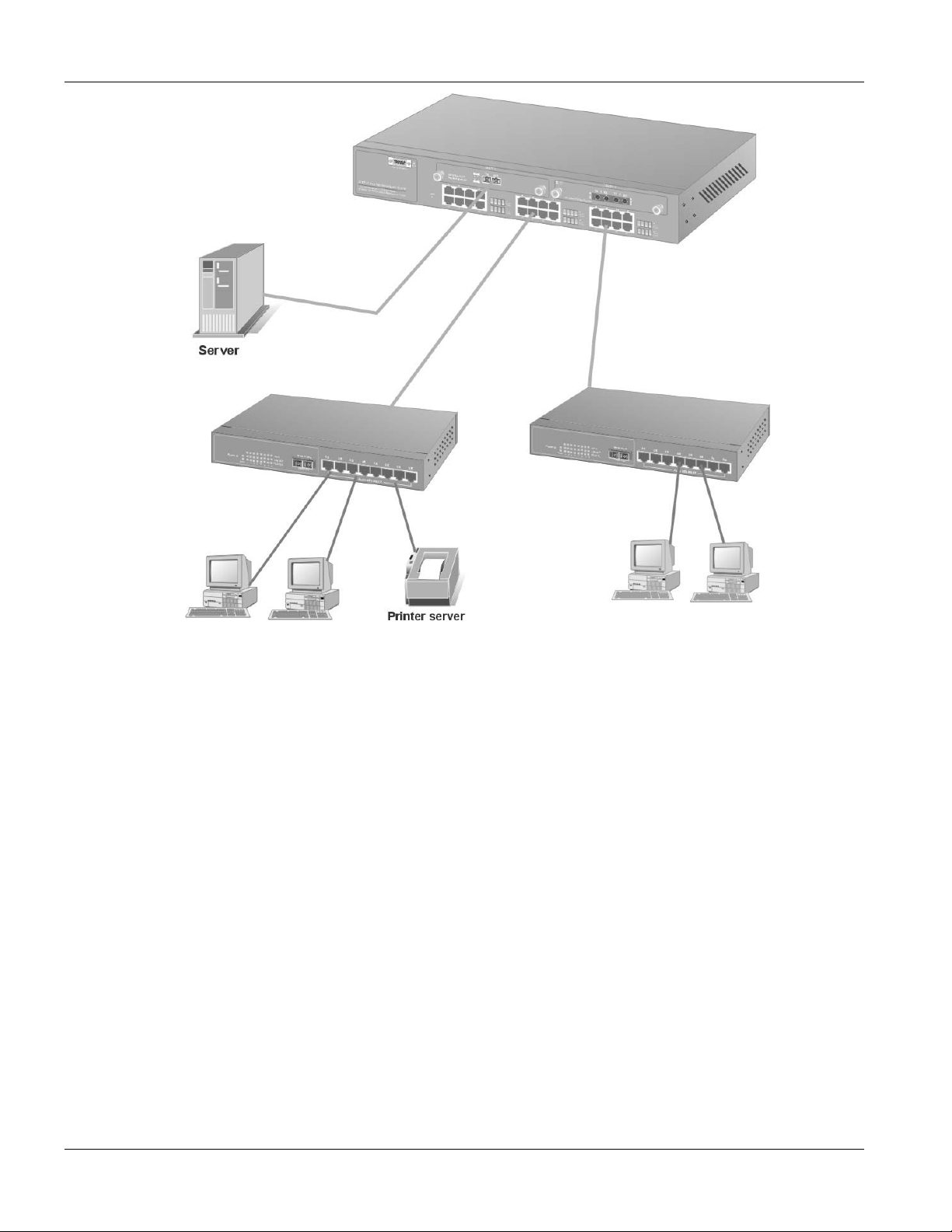
1.5.1 Backbone Application
For small networks where rapid growth can be expected in the near future, the switch is an ideal solution supporting
backbone connectivity.
The switch can be used as a standalone switch for a group of heavy traffic users. Switching is brought to the
desktop either through a single end-station per switch port or through a multi-port switch.
A 1000 Mbps server is connected to the switch providing end stations high-speed accessibility to its applications.
This configuration provides dedicated 100 Mbps connections to the network center, to the server, and up to 40 users
(while 2 Optional 8-port module are installed).
When the network needs expansion, you can simply connect the switch to any IEEE 802.3 ( Ethernet ), IEEE
802.3u ( Fast Ethernet ) and 802.3z ( Gigabit Ethernet ) compliant switch utilizing the Auto MDI/MDIX function.
The switch can also work side by side with a wide range of networking devices (e.g., firewall routers and printer
servers) added to the network.
Getting to Know the EES 1024 1-3
Page 24
EES-1024AF Intelligent Ethernet Switch
Figure 1-1 Backbone Application
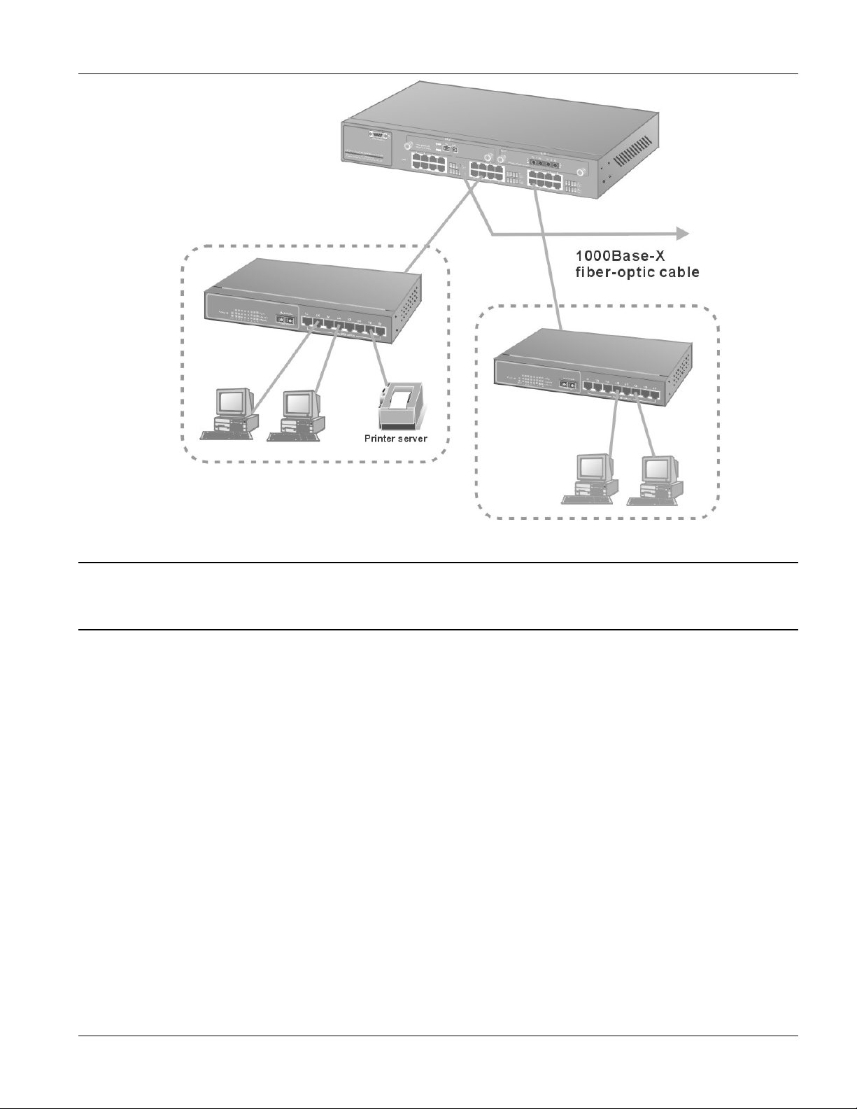
1.5.2 Bridging Example
For enterprise networks where large data broadcasts are constantly processed, the switch is an ideal solution for
department users to connect to the corporate backbone. Used as segment switch, the switch can alleviate user
contention for bandwidth and eliminate server and network bottlenecks. All ports can connect to high-speed
department servers that need high bandwidth. The switch provides parallel communications within its Gigabit port,
which can run up to 2000 Mbps at full-duplex mode.
The switch makes key servers available to more users by allowing multiple conversations to occur concurrently,
thereby significantly expanding overall network throughput. Moreover, the switch eases supervision and
maintenance by allowing network manager centralize multiple servers at a single location.
1-4 Getting to Know the EES 1024
Page 25
EES-1024AF Intelligent Ethernet Switch
Figure 1-2 Bridging Application
Full-duplex mode operation only applies to point-to-point access (for example, when attaching
the switch to a workstation, server, or another switch). When connecting to hubs, use a standard
cascaded connection set for half-duplex operation.
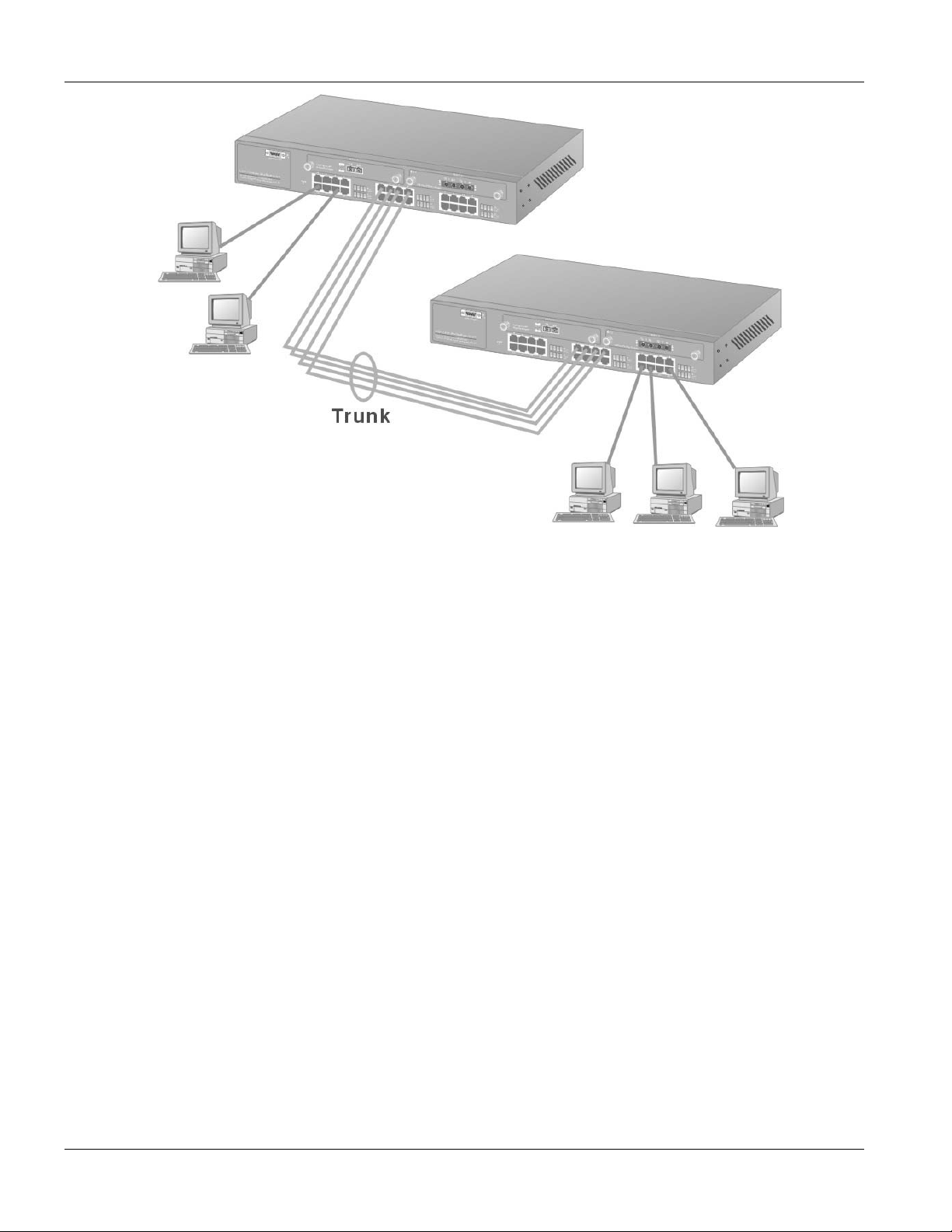
1.5.3 High Performance Switched Workgroup
The switch is ideal for connecting two workgroups, supporting the throughput, for example, of 800Mbps. This
application is useful for power groups that need high bandwidth.
The most common LAN implementations use a combination of standard switches, bridges and routers. The bridges
and routers quickly become bottlenecks, reducing overall network throughput. Switching to higher-speed LANs
such as FDDI or ATM is not a good choice for most people. However, such broadband equipment is still extremely
expensive and difficult to maintain. Besides, you have to replace all existing Ethernet cable and adapter cards,
restructure your network, and implement more expensive administration procedures.
The switch can provide the same bandwidth of FDDI and ATM at much lower costs. In addition, all current
adapters and network devices can still be used. The switching cross-domain connection is better than bridge and
router because the current LAN structure can be retained in which any node can freely communicate with any other
node.
Getting to Know the EES 1024 1-5
Page 26
EES-1024AF Intelligent Ethernet Switch
Figure 1-3 High Performance Switched Workgroup Application
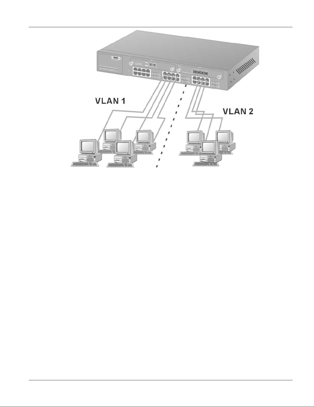
1.5.4 IEEE 802.1Q VLAN Application
The switch supports up to 4095 tag-based IEEE 802.1Q-compatible virtual LAN (VLANs).
Tag-based VLAN Workgroup
You can group the switch ports into broadcast domains by assigning them to the same VLAN to increase network
capacity and performance. With network segmentation, each switch port connects to a segment that is a single
broadcast domain. Packets received in one VLAN can only be forwarded within that VLAN.
VLAN allows the logical grouping of end stations, based not on physical location but on business policies such as
job function or department. Members of a group can be dispersed throughout a facility - they do not have to be
connected in close physical locations.
Hence, group members can coordinate their data communication requirements regardless of the actual working
locations; and the logical network can extend to any point you want it to. Moreover, VLAN groups can be modified
at any time to add, move or change users without any re-cabling.
1-6 Getting to Know the EES 1024
Page 27
EES-1024AF Intelligent Ethernet Switch
Figure 1-4 VLAN Workgroup Application
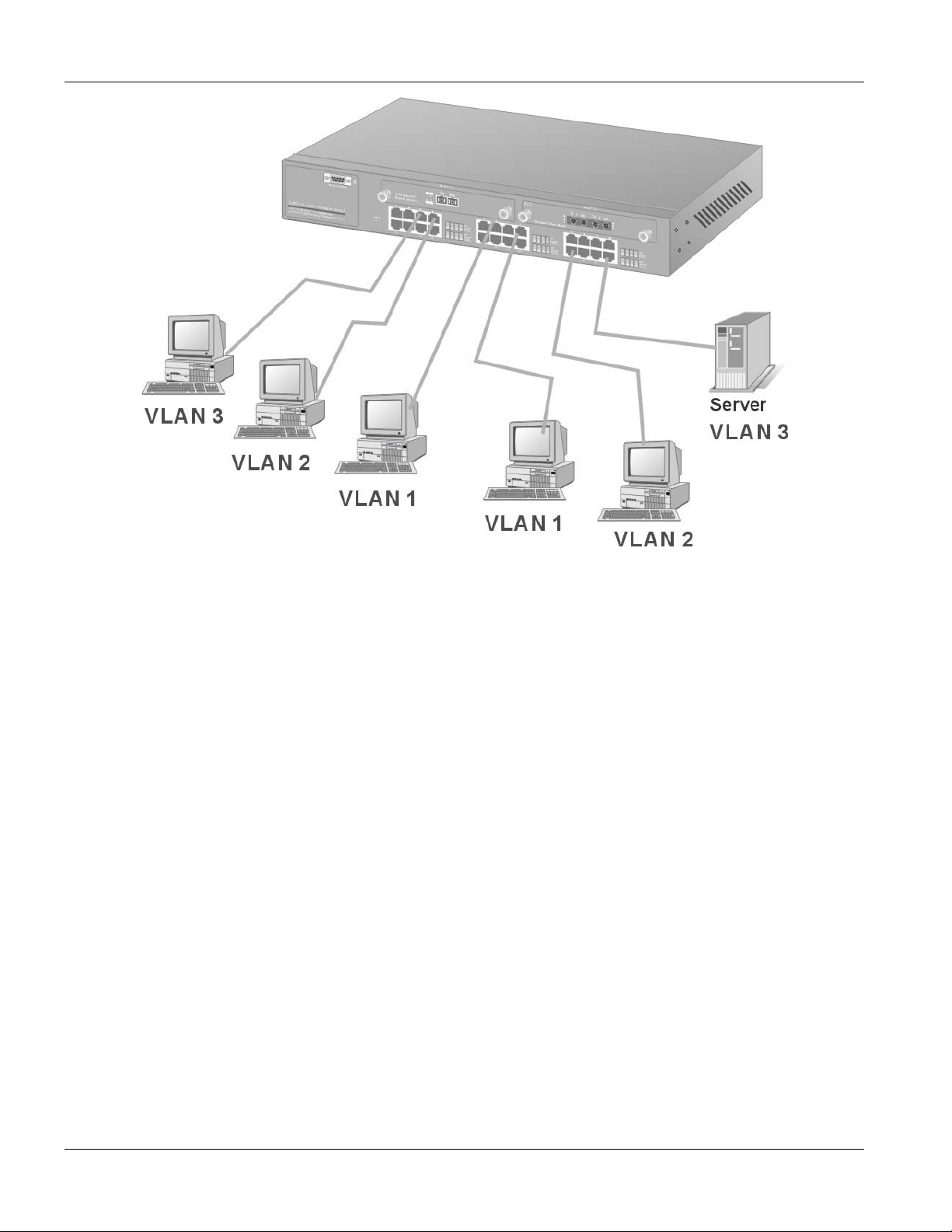
Shared Server
The switch’s compliance to the IEEE802.1Q tagging VLAN standard allows ports to exist in multiple VLANs for
shared resources, such as servers, printers, or Switch-to-Switch connections. It is also possible to have resources
exist in multiple VLANs on one switch as shown in the following figure.
Getting to Know the EES 1024 1-7
Page 28
EES-1024AF Intelligent Ethernet Switch
Figure 1-5 Shared Server
In this example, stations in different VLANs share resources. As a result, VLAN 1 and VLAN 2 can access VLAN
3 for printing. All VLAN port members of VLAN3 can see the broadcasts from ports configured in VLAN3.
1-8 Getting to Know the EES 1024
Page 29
EES-1024AF Intelligent Ethernet Switch
Chapter 2
Hardware
This section describes the hardware of the EES-1024AF Intelligent Switch, and gives a functional
Connections
overview of the switch.
2.1 Hardware Description
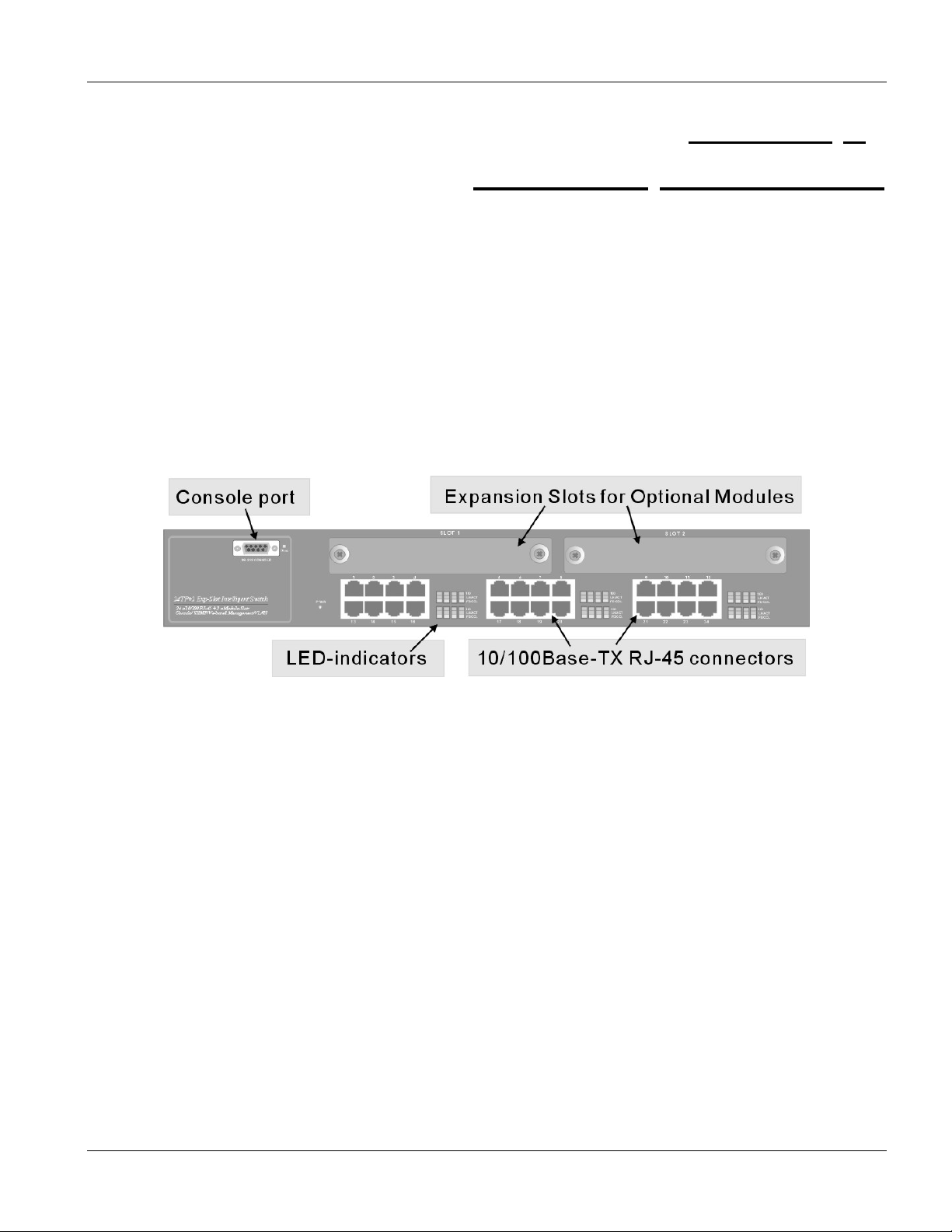
2.1.1 The Front Panel
The front panel of the switch consists of 24 auto-sensing 10/100Mbps Ethernet RJ-45 ports, two optional expansion
slots, and a Console port. The LED indicators are also located on the front panel of the switch.
Figure 2-1 The Front Panel of switch
10/100Base-TX RJ-45 ports (Auto MDI/MDIX):
Your switch comes with 24 10/100Mbps auto-sensing ports for 10Base-T or 100Base-TX devices connections.
With the auto MDI/MDIX feature, you can connect to another switch or workstation without changing to straightthrough or crossover network cables.
Expansion Slots
The chassis of the switch contains two expansion slots. The optional modules come with the built-in CPU module.
You can choose two of the following optional modules. For more information, see the Optional Modules chapter.
• 8-Port 10/100 auto-sensing Intelligent Switch Module
• 2/4-Port 100 Base-FX Intelligent Fiber Module
• Gigabit 1000Base-T Intelligent Switch Modules
• Gigabit 1000Base-SX/LX Intelligent Fiber Modules
Hardware Connections 2-1
Page 30
EES-1024AF Intelligent Ethernet Switch
Console Port
Console management can be done through the Console Port. It requires a direct connection between the switch and
a computer via a RS-232 cable.
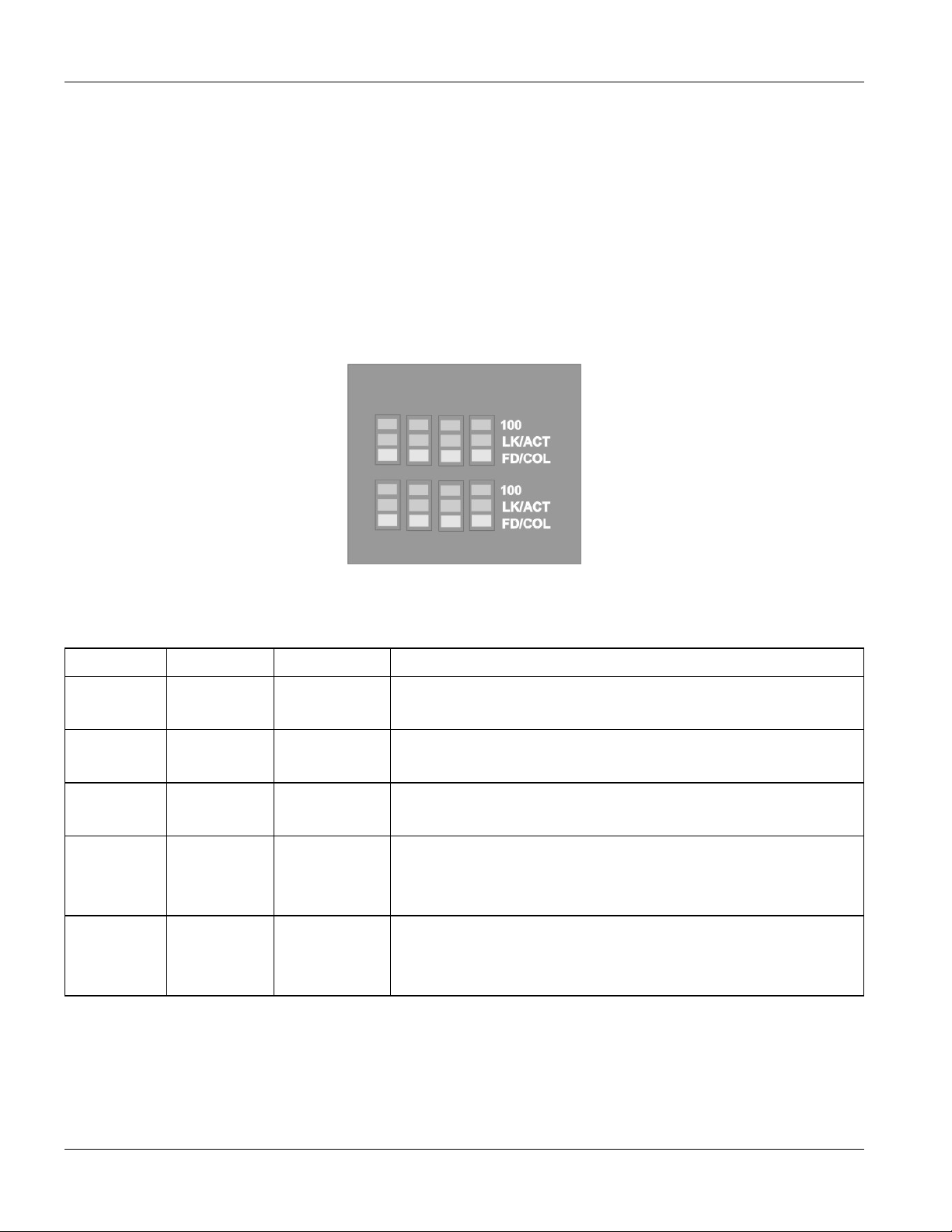
LED Indicators
All LED indicators are located on the front panel of the switch. They provide a real-time indication of system and
operational status. The following table gives descriptions of the LED status and their meanings.
Figure 2-2 The LED
Table 2-1 The LED Descriptions
LED COLOR STATUS DESCRIPTION
PWR Green
ALM Red
100 Green
LK/ACT Green
FD/COL Yellow
ON The system is turned on.
OFF The system is off.
ON The system is functioning abnormally.
OFF The system is functioning normally.
ON The link to a 100 Mbps Ethernet network is up.
OFF No device attached or in 10Mbps mode.
ON The port is connected with a device.
Blinking The port is receiving or transmitting data.
Off No device attached.
ON The port is operating in Full-duplex mode.
Blinking Packet collision occurred.
OFF No device attached or in half-duplex mode.
2.1.2 Rear Panel
The 3-pronged power plug and the On/off switch are located at the back of the switch. The ventilation fan is located
on the side of the switch. The switch works with AC in the range 100-240V AC, 50-60Hz.
2-2 Hardware Connections
Page 31

EES-1024AF Intelligent Ethernet Switch
Figure 2-3 The Rear Panel of the switch
Power On
After all network cables are connected, plug the power cord into the power socket on the back panel and the other
end into a power outlet. Turn the power on using the power Switch on the back panel. The switch uses a universal
power supply that requires no additional adjustment. Check the front panel PWR LED to see if power is properly
supplied.
Diagnostic Test
After the installation is completed and AC power is applied, the switch will automatically perform a diagnostic test.
When the Power LED is on within 5 seconds, the Diagnostic status LEDs will soon flash red.
When the switch passes the self-test within 15 seconds, the Link /ACT LED turns on.
If the switch fails the self-test, the ALM LED will blink.
2.2 Mounting the EES-1024AF
The switch is suitable for use in an office environment where it can be rack-mounted in standard EIA 19-inch racks
or standalone.
For proper ventilation, allow about at least 4 inches ( 10 cm ) of clearance on the front and 3.4
inches ( 8 cm ) on the back of the switch. This is especially important for enclosed rack
installation.
2.2.1 Desktop Mounting
Step 1. Make sure the switch is clean and dry.
Step 2. Set the EES-1024AF on a smooth, level and sturdy flat space strong enough to support the weight of the
EES-1024AF and the attached cables with a power outlet nearby.
Step 3. Make sure there is enough clearance around the EES-1024AF to allow air circulation and the attachment
of cables and the power cord.
Hardware Connections 2-3
Page 32

EES-1024AF Intelligent Ethernet Switch
Step 4. Remove the adhesive backing from the supplied rubber feet.
Step 5. Attach the rubber feet to each corner on the bottom of the EES-1024AF. These rubber feet help protect
the EES-1024AF from shock or vibration and ensure space between devices when stacking.
Figure 2-4 Attaching Rubber Feet to each corner on the bottom of the switch
Do not block the ventilation holes. Leave space between switches when stacking.
2.2.2 Rack-mounted Installation
The EES-1024AF can be mounted on a 19-inch rack or in a wiring closet with other equipment. Follow the steps
below to mount your EES-1024AF on a 19-inch rack using the included rack-mounting kit.
Step 1. Align one bracket with the holes on one side of the EES-1024AF and secure it with the bracket screws
smaller than the rack-mouting screws. Similarly, attach the other brackets
Figure 2-5 Attach mounting brackets with screws
Step 2. After attaching both mounting brackets, position the EES-1024AF in the rack by lining up the holes in
the brackets with the appropriate holes on the rack. Secure the EES-1024AF to the rack with the rackmounting screws.
2-4 Hardware Connections
Page 33

EES-1024AF Intelligent Ethernet Switch
Figure 2-6 Mount the switch in an EIA standard 19-inch Rack
Hardware Connections 2-5
Page 34

Page 35

EES-1024AF Intelligent Ethernet Switch Optional Modules Guide
Chapter 3
Optional
Modules
3.1 Introduction1
With the EES switch’s two expansion slots, you can use optional modules that allow your EES switch to provide
10/100 Mbps and 1000 Mbps connections to other compatible network devices. The optional modules are designed
to expand your network area.
You can choose from the following to optimize your network’s performance while reducing cost and complexity
1-port Gigabit 1000Base-T Intelligent module
1-port Gigabit 1000Base-SX/LX Fiber Intelligent modules
8-port 10/100 auto-sensing Intelligent module
2-port/ 4-port 100Base-FX Fiber Intelligent modules
The following sections provide a brief description of each optional module.
3.2 EM1024A-8TP: 8-Port 10/100 auto-sensing Intelligent
Switch Module
Figure 3-1 EM1024A-8TP Front Panel
Features
• Eight 10/100Mbps Ethernet switch ports
• Supports auto MDI/MDIX (auto-sensing) for all 10/100Base-TX ports
• Auto-negotiation support on all ports
• Back-Pressure-Base flow control on half-duplex ports
• Pause-Frame-Base flow control on full-duplex ports
1
The list of modules is correct at the time of writing. It is subjected to change without notice.
Optional Modules 3-1
Page 36

EES-1024AF Intelligent Ethernet Switch Optional Modules Guide
• Supports store-and-forward switching
• Supports non-blocking and full wire speed forwarding rate
• 4K-entry MAC address table
• 100M, LK/ACT, FD/COL LEDs
• Supports SNMP management
Front Panel LEDs
There are three types of LEDs for each RJ-45 port.
Table 3-1 EM1024A-8TP LED Description
LED COLOR STATUS DESCRIPTION
100 Green On An Ethernet device is connected at 100 Mbps.
Off An Ethernet device is connected at 10Mbps.
LK/ACT Green On The port is connected to an Ethernet device.
Blinking The port is transmitting or receiving data.
FD/COL Yellow On The port is operating in full-duplex mode.
Blinking Packet collision occurred on this port.
Off The port is operating in half-duplex mode.
3.3 EM1024A-GTP: Gigabit 1000Base-T Intelligent Switch
Module
Figure 3-2 EM1024A-GTP Front Panel
Features
• Gigabit Media Independent Interface (GMII) compliant
• One 100/1000Mbps N-Way auto-negotiation switch port
• Standard auto-negotiation, duplex modes and flow control for MII and GMII PHY
• Supports full-duplex at 1000Mbps on GMII interface
• Supports auto MDI/MDIX (auto-sensing)
3-2 Optional Modules
Page 37

EES-1024AF Intelligent Ethernet Switch Optional Modules Guide
• 128Kb memory buffer sharing
• Supports store-and-forward switching
• Supports half-duplex and full-duplex modes at 10/100 Mbps on MII interface
• 1000M, 100M, LK/ACT and FD/COL LEDs
Front Panel LEDs
There are four LEDs for the RJ-45 port.
Table 3-2 EM1024A-GTP LED Description
LED COLOR STATUS DESCRIPTION
1000M Green On An Ethernet device is connected at 1000 Mbps.
Off An Ethernet device is connected at 10 Mbps or is not connected.
LK/ACT Green On
Blinking
Off
100M Green On An Ethernet device is connected at 100 Mbps.
Off An Ethernet device is connected at 10 Mbps or is not connected.
FD/COL Yellow On
Blinking
Off
The port is connected to an Ethernet device.
The port is receiving or transmitting data.
No Ethernet device is connected to this port.
The port is operating in full-duplex mode.
Collisions occurred.
The port is operating in half-duplex mode.
3.4 100Base-FX Fiber Intelligent Module Series
3.4.1 EM1024A-2FX-SC: 2-Port 100Base-FX (Multi-mode) Intelligent Fiber Module
Figure 3-3
EM1024A-2FX-SC Front Panel
Optional Modules 3-3
Page 38

EES-1024AF Intelligent Ethernet Switch Optional Modules Guide
3.4.2 EM1024A-4FX-SC: 4-Port 100Base-FX (Multi-mode) Intelligent Fiber Module
Figure 3-4
Features
EM1024A-4FX-SC Front Panel
• Two/Four 100Mbps fiber ports (SC connectors)
• 5MB memory buffer
• 12K-entry MAC address table
• Supports store-and-forward switching
• Supports half-duplex and full-duplex modes
• LK/ACT and FD/COL LEDs
• Supports connection distance of up to 2 kilometers via fiber optic cable.
• Supports SNMP management
3.4.3 EM1024A-2FX-SC-30: 2-Port 100Base-FX (Single-mode) Intelligent Fiber Module
Figure 3-5
3-4 Optional Modules
EM1024A-2FX-SC-30 Front Panel
Page 39

EES-1024AF Intelligent Ethernet Switch Optional Modules Guide
3.4.4 EM1024A-4FX-SC-30: 4-Port 100Base-FX (Single-mode) Intelligent Fiber Module
Figure 3-6
Features
EM1024A-4FX-SC-30 Front Panel
• Two/Four 100Mbps fiber ports (SC connectors)
• 5MB memory buffer
• 12K-entry MAC address table
• Supports store-and-forward packet filtering
• Supports half-duplex and full-duplex modes
• LK/ACT and FD/COL LEDs
• Supports connection distance of up to 30 kilometers via fiber optic cable.
• Supports SNMP management
Front Panel LEDs
There are two LED indicators for each fiber port.
Table 3-3 100Base-FX Fiber Module Series LED Description
LED COLOR STATUS DESCRIPTION
LK/ACT Green On The port is connected to an Ethernet device.
Blinking The port is transmitting or receiving data.
Off The port is not connected to an Ethernet device.
FD/COL Yellow On The port is operating in full-duplex mode.
Blinking Data packet collision occurred on this port.
Off The port is operating in half-duplex mode.
Optional Modules 3-5
Page 40

EES-1024AF Intelligent Ethernet Switch Optional Modules Guide
3.5 Gigabit 1000Base-X Intelligent Fiber Module Series
3.5.1 EM1024A-SX-SC: Gigabit 1000Base-SX Intelligent Module
Figure 3-7
Features
EM1024A-SX-SC Front Panel
• One auto-negotiating 1000Mbps fiber port (SC connectors)
• 4K MAC address table
• Supports store-and-forward switching
• LK, ACT, FD and COL LEDs
• Supports connection distance of up to 220 meters (using 62.5/125um Multi-mode fiber) and up to 500 meters
(using 50/125um Multi-mode fiber) via fiber optic cable.
• Supports SNMP management
3.5.2 EM1024A-LX-SC: Gigabit 1000Base-LX Intelligent Module
Figure 3-8
Features
EM1024A-LX-SC: Front Panel
• One auto-negotiating 1000Mbps fiber port (SC connectors)
• 4K MAC address table
• Supports store-and-forward switching
3-6 Optional Modules
Page 41

EES-1024AF Intelligent Ethernet Switch Optional Modules Guide
• LK, ACT, FD and COL LEDs
• Supports connection distance of up to 10 kilometers (using 9/125um Single-mode fiber) via fiber optic cable.
• Support SNMP management
Front Panel LEDs
There are four LED indicators for the fiber port.
Table 3-4 Gigabit 1000Base Intelligent Module Series LED Description
LED COLOR STATUS DECRIPTION
LK Green On The port is connected to an Ethernet device.
Off The port is not connected to an Ethernet device.
ACT Green Blinking The port is transmitting or receiving data.
FD Yellow On The port is operating in full-duplex mode.
Off The port is operating in half-duplex mode.
COL Yellow Blinking Data packet collision occurred on this port.
3.6 Installing Optional Modules
You can install two optional modules separately to meet the needs of your network. The procedure for installing the
optional modules is the same. Follow these steps to install the optional modules.
Step 1. Turn off your switch and unplug the power cord from the switch.
Step 2. Loosen the thumbscrews from the cover plate and remove the cover plate from the optional slot. Do not
discard the cover plate. You can put the cover plate back on if you remove the new module.
Figure 3-9 Loosening the Screws and Removing the Cover Plate
Step 3. Ground yourself by wearing an anti-static wrist strap or touching any grounded or metal objects before
you continue.
Step 4. Remove the optional module from its protective anti-static packaging. Avoid touching the onboard
circuit components by holding it by the edge.
Step 5. Insert the optional module into an avaliable expansion slot on the switch. Press it firmly until the
optional module snaps into place and secure it to the switch with the retaining screws.
Optional Modules 3-7
Page 42

EES-1024AF Intelligent Ethernet Switch Optional Modules Guide
Slide the optional module
into the expansion slot until
it snaps into place.
Figure 3-10 Inserting the optional module
Never force, bend or twist the optional modules into the expansion slots.
Step 6. Turn on the switch. The switch automatically detects the installed optional module. Connect any
necessary network cables to the optional module and check the LEDs to verify that it is functioning
properly.
3-8 Optional Modules
Page 43

EES-1024AF Intelligent Ethernet Switch Optional Modules Guide
Chapter 4
Introducing
This chapter introduces the basics of SMT.
the SMT
4.1 Connecting to the Console Port
The Console configuration (out of band) allows you to set your switch to enable a user at a remote console terminal
to communicate with the switch as if the console terminal were directly connected to it.
The Console port uses a male DB-9 connector to connect to a computer or terminal for monitoring and configuring
the switch. Use the supplied RS-232 cable with a female DB-9 connector to connect a terminal or computer to the
Console port.
Figure 4-1 Connecting the Switch to a terminal via RS-232 cable
4.2 Establishing the Console Port Connection
After the switch is connected to a computer, turn on the computer and run a terminal emulation program (i.e. Hyper
Terminal in Windows) and configure its communication parameters to match the following default characteristics
of the console port.
Introducing the SMT 4-1
Page 44

EES-1024AF Intelligent Ethernet Switch
Figure 4-2 Parameter settings of communication parameters in Hyper Terminal
Table 4-1 Field Values for Hyper Terminal in Windows
FIELD VALUE
Baud Rate 9600 bps
Data Bits 8
Parity none
Stop Bit 1
Control flow None
4.2.1 Initial Screen
At the prompt, type go and press [ENTER] to display the main screen as shown next.
Type ‘go’ to enter main menu: go
Figure 4-3 SMT - Initial Screen
4.2.2 Password Screen (optional)
If you enabled the console password login option, the following screen displays. To disable or enable this option,
see 4.4.2 Enable Console Login
Login: root
Password:
User root logged in
Type ‘go’ to enter main menu or ‘exit’ to logout: go
Figure 4-4 SMT - Login
4-2 Introducing the SMT
Page 45

EES-1024AF Intelligent Ethernet Switch Optional Modules Guide
4.3 Navigating the SMT Interface
The SMT (System Management Terminal) is the interface you use to manage your switch through the Console port
or Telnet. Several operations that you should be familiar with before you attempt to modify the configuration are
listed in the following table.
Table 4-2 Navigating the SMT
OPERATION KEYSTROKE DESCRIPTION
Move down to
another menu
Move up to a
previous menu
[ENTER] To move forward to a submenu, type in the number or alphabet of the
desired submenu and press [ENTER].
Type q or Q, then
To move back to the previous menu, type q or Q and press [ENTER].
press [ENTER]
Entering information [ENTER] Type in the number or alphabet of the desired field, type in the
appropriate information and press [ENTER].
Save your
configuration
[ENTER] Save your configuration by pressing [ENTER] at the message “Press
ENTER to confirm or ESC to cancel”. Saving the data on the screen
will take you, in most cases to the previous menu.
Exit the SMT Type q or Q, then
press [ENTER]
Type q or Q at the main menu prompt and press [ENTER] to exit the
SMT interface.
4.3.1 The Main Menu
After you log in, the SMT displays the Main Menu.
[Main]
1. Device Settings
2. Ports Settings
3. Address Table
4. Spanning Tree Protocol
5. Broadcast Storm Filter
6. IGMP
V. VLAN Mode (2 modes)
C. VLAN for CPU (2 VLANs)
I. Secure IP for Telnet and HTTP
S. Save Current Settings
D. Factory Default Settings & Reboot System
R. Reboot System
Q. Quit
Select one function (1-6, V, C, I, S, D, R, Q):
Figure 4-5 SMT- Main Menu
Table 4-3 SMT Main Menu Summary
# MENU TITLE DESCRIPTION
1 Device Settings Use this menu to enter administrative information.
2 Port Settings Use this menu to set the port settings for each port.
3 Address Table Use this menu to display address information of each port.
Introducing the SMT 4-3
Page 46

EES-1024AF Intelligent Ethernet Switch
Table 4-3 SMT Main Menu Summary
# MENU TITLE DESCRIPTION
4 Spanning Tree Protocol Use this menu to enable or disable the Spanning Tree Protocol and show the
port status.
5 Broadcast Storm Filter Use this menu to enable or disable the Broadcast Storm filters.
6 IGMP Use this menu to enable or disable the IGMP.
V VLAN Mode (2 modes) Use this menu to set the VLAN modes.
C VLAN for CPU (2 VLANs Use this menu to set VLAN ID for managed CPU.
I Secure IP for Telnet and
HTTP
Use this menu to enable or disable secure IP for Telnet or HTTP and specify the
secure IP address(es).
S Save Current Settings Select this option to save your current custom settings.
D Factory Default Settings
and Reboot System
Select this option to reset the switch to factory default settings and reboot the
system. This will erase all your custom settings.
R Reboot System This option reboots the system and makes all new settings take effect.
Q Quit To exit the SMT menu, you must type ‘q’ or ‘Q’.
The SMT is not case sensitive; therefore you can type either “q” or “Q” at the prompt to exit.
4.4 Device Settings
4.4.1 Changing Your System Password
It is important to change the system password or login name by doing the following:
Step 1. Enter 1 from the main menu. This will bring up Device Setting as shown.
[Main] [Device Settings]
0.1 Version (RO): 1.01.1, Mar. 20, 2002
0.2 MAC Address (RO): 00-00-1c-f3-0c-02
0.3 System Up Time (RO): 0 days 0 hours 3 minutes 59
seconds
1. System Name: EES 1024AF
2. System Location: 2
3. System Contact: Someone
4. IP Address: 192.168.1.1
5. Subnet Mask: 255.255.255.0
6. Default Gateway: 192.168.1.10
7. Change User/Password: root/root
8. Console Login Enabled: Yes
Q. Quit
Note: please save settings and reboot system
so that your device settings will take effect
Select one function (1-8, Q): 7
Figure 4-6 SMT - Device Settings
Step 2. Enter 7 to select the Change User/Password option.
Step 3. Type in the new username and enter the new password twice.
4-4 Introducing the SMT
Page 47

EES-1024AF Intelligent Ethernet Switch Optional Modules Guide
The SMT will return to the Device Settings screen. You should see your new user name and the password will be
shown as “********”.
4.4.2 Enable Console Login
ZyXEL strongly recommend that you enable the console login feature for security.
Step 1. In the Device Settings menu, Enter 8 to select the Console Login Enabled option.
Step 2. Enter “y” at the “Input Yes or No (Y, N):” prompt.
4.4.3 Assigning IP Address
Once you have logged into the switch, you need to assign an IP address to the Ethernet Interfaces of the switch so
that you can connect to and manage the switch using a web browser. Follow the steps to assign an IP address to
your switch:
Step 1. In the Device Settigns menu, enter 4 to select IP Address.
Step 2. Enter a unique IP address for the switch, and then press [ENTER]. ( Default IP address is 192.168.1.1 )
Step 3. Enter 5 to select Subnet Mask, and enter the subnet mask ( IP Net mask ) address. ( Default subnet
Mask is 255.255.255.0 )
Step 4. Enter 6 to Select Default Gateway, and enter the IP address of the default gateway if you are sending
packets to another IP network. ( Default Gateway is 192.168.16. 254 )
The gateway address is the router that can forward packets to the other IP networks
Return to the main menu to execute S (Save Current Settings) and R (Reboot System) to make your new settings
take effect.
.
4.5 Save and Reboot
Once you have make new changes using the SMT you have to save the new settings and reboot your switch.
4.5.1 Save Current Settings
You must save the new settings to the switch before rebooting. Follow the steps to save the current settings.
Step 1. Enter “s” from the SMT main menu.
Step 2. Enter “y” at the prompt to continue saving and press [ENTER]. Once you save the current settings to the
switch, you will not be able to get back the old settings. Enter “n” to cancel.
Step 3. Wait for a moment. The SMT will return to the main menu after the saving the current settings.
Introducing the SMT 4-5
Page 48

EES-1024AF Intelligent Ethernet Switch
[Main] [Save Current Settings]
Are you sure? (Y, N): y
save current settings...
done...
Figure 4-7 SMT – Save Current Settings
4.5.2 Reboot Your EES-1024AF
Follow the steps to reboot the switch. Rebooting will make all new settings take effect.
Step 1. Enter “r” from the SMT main menu.
Step 2. Enter “y’” at the prompt to continue the reboot process. Otherwise enter “n” to return to the main menu.
Step 3. Wait for about 30 seconds before the SMT prompts you to log in again.
[Main] [Reboot System]
Are you sure? (Y, N): y
reboot system.
24-port 10/100Base-TX + 2 expansion modules switch is
starting...
Figure 4-8 SMT - Reboot System
4.6 Resetting the EES-1024AF
You can reset the switch to the factory default values. All your custom configurations will be lost except the IP
address of the switch.
Step 1. Enter “d” from the main menu.
Step 2. Enter “y” to continue the reset process. Otherwise enter “n” to returnt to the main menu.
Step 3. Wait for a moment while the switch reboots and prompts you to log in again.
4-6 Introducing the SMT
Page 49

Getting Started
Part II:
Getting Started
This part shows you how to configure the basic setup using the SMT menus and introduces you
to the Web Configurator.
II
Page 50

Page 51

EES-1024AF Intelligent Ethernet Switch
Chapter 5
General
Setup Using the SMT
This chapter shows you basic configuration using the SMT.
5.1 Ethernet Port Settings
Ethernet port connections can be in half-duplex or full-duplex mode. The Ethernet port must use the same speed or
duplex mode setting as the peer Ethernet port in order to connect.
Enter 2 from the main menu, and then type in the port number to bring up the Port Settings menu for the specified
port.
[Main] [Ports Settings]
module: 0, port: 1
0.1 Link (RO): Up
0.2 Speed/Duplex (RO): 100/Full
1. Port Enabled: Enabled
2. Speed/Duplex: Auto
3. Flow Control: Enabled
4. Back Pressure: Enabled
5. VLAN Tagged: No
6. Default VLAN ID: 1
7. Note:
Q. Quit
Select one function (1-7, Q):
Figure 5-1 SMT - Port Settings
At the prompt, type the corresponding numerical numbers to configure. The Port Settings fields are explained in
the table below.
Table 5-1 Port Settings Fields
# FIELD DESCRIPTION EXAMPLE
0.1 Link This read-only field indicates the connection status of the port. Up
0.2 Speed/Duplex This read-only field shows the actual speed and the duplex mode of the
port.
1 Port Enabled Select this option to enable or disable the port. Enabled
2 Speed/Duplex Set the port speed and duplex mode with this option. The switch will auto
detect the speed and duplex mode of the attached device if you select
Auto; otherwise check the settings of the device attached to this port and
select from the following: 100/Full, 100/Half, 10/Full, and 10/Half.
3 Flow Control When this option is enabled, the switch sends a PAUSE message to the
device to pause the transmission when the buffer in the switch is full. This
works only for devices in full-duplex mode.
4 Back Pressure When this option is enabled, the switch sends a Back Pressure message to
the device to pause the transmission when the buffer in the switch is full.
This works only for devices in half-duplex mode.
100/FULL
Auto
Enable
Enable
General Setup Using the SMT 5-1
Page 52

EES-1024AF Intelligent Ethernet Switch
Table 5-1 Port Settings Fields
# FIELD DESCRIPTION EXAMPLE
5 VLAN Tagged The VLAN ID will be tagged to the transmitted packets through the port.
6 Default VLAN ID Select this option to set the default VLAN ID. You can select from 1 to
No
1
4095.
7 Note This option allows you to enter additional information for the port. This will
not affect the current configuration. Maximum 16 characters.
When you have completed this menu, type “q” and press [ENTER] at the prompt go back to the Port Settings main
menu. You can type “q” at any time to cancel.
5.2 View Your Port Information
You can view the MAC address and the VLAN ID of a specific port in Address Table. Follow the steps to view all
your port information.
Step 1. Enter 3 from the main menu the to bring up the Address Table menu.
Step 2. Enter 1 and press [ENTER] to display information on all ports currently connected to the switch.
[Main] [Address Table]
1. All
2. Module
3. Module Port
Q. Quit
Select one function (1-3, Q): 1
============================================================
[Main] [Address Table] [All]
Module Port MAC-Address VLAN
------ ---- ----------------- ---0 1 00-50-ba-ad-4f-81 1
============================================================
Figure 5-2 SMT - Address Table (All)
You can also select options 1 and 2 to display port information on a specific module.
5.3 Spanning Tree Protocol (STP)
Enable or disable the spanning tree protocol by following the steps.
Step 1. Enter 4 from the main menu to display the Spanning Tree Protocol page.
Step 2. Enter 1 to enable or 2 to disable the spanning tree protocol.
Step 3. Once the spanning tree protocol is enabled, you can enter 3 at the prompt the view port status for each
port.
5-2 General Setup Using the SMT
Page 53

[Main] [Spanning Tree Protocol]
Current state: Enabled
1. Enable
2. Disable
3. Show Port State
Q. Quit
Select one function (1-3, Q): 3
============================================================
[Main] [Spanning Tree Protocol] [Show Port State]
Module Port State
------ ---- -----------0 1 Listening
0 2 Not connected
0 3 Not connected
Press 'ENTER' key to continue...
Figure 5-3 SMT - Spanning Tree Protocol with Port Status
5.4 Broadcast Storm Filter
Follow the steps to enable or disable the broadcast storm filter.
EES-1024AF Intelligent Ethernet Switch
Step 1. Enter 5 from the main menu to bring up the Broadcast Storm Filter page.
Step 2. Enter 1 to enable or 2 to diable the filter at the prompt.
[Main] [Broadcast Storm Filter]
Current state: Enabled
1. Enable
2. Disable
Q. Quit
Select one function (1-2, Q): 1
Figure 5-4 SMT - Broadcast Storm Filter
5.5 Internet Group Management Protocol (IGMP)
Follow the steps to enable or disable the IGMP
Step 1. Enter 6 from the main menu to open IGMP page.
Step 2. Enter 1 to enable or 2 to disable the IGMP.
General Setup Using the SMT 5-3
Page 54

EES-1024AF Intelligent Ethernet Switch
[Main] [IGMP]
Current state: Enabled
1. Enable
2. Disable
Q. Quit
Select one function (1-2, Q):
Figure 5-5 SMT - IGMP
5.6 Setting the VLAN Mode
Follow the steps to set the VLAN mode.
Step 1. Enter “v” from the main menu to open the VLAN Mode page.
Step 2. Enter one of the two modes at the prompt.
[Main] [VLAN Mode]
Current mode: 1
1. VLAN is valid for all packets
2. VLAN is valid for broadcast and multicast packets, not for
unicast packets.
For SmartBits test, this mode will get better throughput.
Q. Quit
Select one function (1-2, Q):
Figure 5-6 SMT - VLAN Mode
5.7 Setting the VLAN for CPU
To set the VLAN for CPU enter “c” from the main menu to open the VLAN for CPU page.
[Main] [VLAN for CPU]
1. Current first VLAN for CPU: VLAN ID 1
2. Current second VLAN for CPU: None
Q. Quit
Select one function (1-2, Q): 1
Figure 5-7 SMT - VLAN for CPU
Table 5-2 Fields in VLAN for CPU options
# FIELD DESCRIPTION EXAMPLE
Current first
1
VLAN for CPU
Current second
2
VLAN for CPU
Select this option and enter the VLAN ID for the
first CPU. You can choose from ID 1 to 4095.
Select this option and enter the VLAN ID for the
second CPU. You can choose from ID 1 to 4095.
1
None
Press “q” to exit this menu.
5-4 General Setup Using the SMT
Page 55

EES-1024AF Intelligent Ethernet Switch
5.8 Configure Secure IP Addresses
When the secure IP for Telnet or HTTP is enabled, only those IP address(es) specified in this screen will be able to
Telnet to the switch or login using the Web Configurator. You can specify up to 4 IP addresses. If either secure IP
feature is enabled without specifying an IP address, no device will be able to log into the switch using that login
method.
Enabling the secure IP feature will not affect console port login.
ZyXEL recommend that you enable the Secure IP for HTTP option if the switch is on the public
network.
Enter “i” from the main menu to bring up the Secure IP screen.
Figure 5-8 SMT – Secure IP
[Main] [Secure IP]
1. Secure IP for Telnet: Enabled
2. Secure IP for HTTP: Enabled
3. Secure IP 1: 192.168.1.10
4. Secure IP 2:
5. Secure IP 3:
6. Secure IP 4:
Q. Quit
Note: We suggest that you enable the HTTP
option if the management CPU
uses an Internet real IP
Select one function (1-6, Q):
Table 5-3 Fields in Secure IP
# FIELD DESCRIPTION EXAMPLE
1
2
3 .. 6
Secure IP for
Telnet
Secure IP for
HTTP
Secure IP 1 .. 4 Select these options to specify secure IP
Select this option and enable or disable the
secure IP for Telnet sessions.
Select this option and enable or disable the
secure IP for HTTP sessions.
address(es)
Enabled
Enabled
192.168.1.10
Press “q” to exit this menu.
5.9 General Setup Complete
The SMT allows you to configure basic settings of the switch. Use the embedded Web Configurator to configure
advanced settings as described next.
General Setup Using the SMT 5-5
Page 56

Page 57

EES-1024AF Intelligent Ethernet Switch
Chapter 6
Using
This section introduces the configuration and functions of the Web Configurator.
the Web Configurator
6.1 Introduction
The embedded Web Configurator offers advanced management features and allows you to manage the switch from
anywhere on the network through a standard browser such as Microsoft Internet Explorer or Navigator.
The Web Configurator supports Internet Explorer 4.0 and Netscape Communicator 4.x and later versions. It is
based on Java Applets with an aim to reduce network bandwidth consumption, enhance access speed and present an
easy viewing screen.
By default, Internet Explorer 4.0 does not allow Java Applets to open sockets. The user has to
explicitly modify the browser setting to enable Java Applets to use network ports. See Appendix
A Microsoft Internet Explorer Setup. You don’t need to change any configuration if you use
Netscape browser. However, Netscape browser doesn’t support TFTP firmware upgrade.
6.2 System Login
Disconnect the Console port connection before launching the Web Configurator.
Step 1. Start Internet Explorer or Netscape Communicator web browser.
Step 2. Type http:// and the IP address of the switch ( for example, the default is 192.168.1.1 ) in the Location or
Address field. Press Enter.
Step 3. The Password screen appears. Type user name and password. The default is root for both.
Figure 6-1 Web Configurator - Login
Step 4. Click Ok. The Home page of the Web Configurator displays.
Using the Web Configurator 6-1
Page 58

EES-1024AF Intelligent Ethernet Switch
6.3 Navigating the Web Configurator
6.3.1 Task Bar
The task bar displays at the left of all web pages provides a consistent way to access all program functions.
Figure 6-2 Web Configurator - Navigation Bar
6.3.2 The Web Configurator Front Panel Display
The Web Configurator displays the front panel of your switch at the top of every web page. The front panel shows
the modules installed in the switch and the link status of all ports. The link status information is updated each time
the Web Configurator polls the switch. The colors of the LED indicate the operating status of the port.
Table 6-1 Web Configurator - Front Panel LED Color Descriptions
COLOR LINK STATUS
Orange The port is operating at 10 Mbps.
Green The port is operating at 100 Mbps.
Yellow The port is operating at 1000 Mbps.
White The port is disabled by the Spanning Tree Protocol.
6-2 Using the Web Configurator
Page 59

EES-1024AF Intelligent Ethernet Switch
Figure 6-3 Web Configurator - Front Panel
A yellow “X” indicates a port is disabled. To view port information, click on the ports to open the Ports page. See
7.1 Port Management for information on configuring the ports.
6.3.3 Commonly Used Buttons
The table describes the actions related to the buttons display at the bottom of the web pages.
Table 6-2 Commonly Used Buttons
BUTTON FUNCTION
Click this button to apply your new settings to the current runny configuration.
The new configuration will not take effect until you save and reboot your switch.
See 8.1Save and Reboot.
Click this button to clear the information you have just entered. The procedure
works only if you have not yet click Apply before you click Undo.
6.4 Viewing Basic System Information
The Home page displays when you first access the Web Configurator.
Using the Web Configurator 6-3
Page 60

EES-1024AF Intelligent Ethernet Switch
Figure 6-4 Web Configurator - Home
Table 6-3 Home Page Field Description
FIELD DESCRIPTION EXAMPLE
System Name Displays the descriptive name for identification purposes. EES 1024AF
System Location The physical location of the switch. somewhere
System Contact The name of the person in charge of this switch. someone
Note: You can change the above three fields in the SNMP page.
System Up Time Indicates the time since the managed unit was re-
initialized.
IP Address The IP Address of the managed unit.
Subnet Mask The subnet mask of the managed unit.
Default Gateway The default outgoing gateway of the managed unit.
Note: You can change the IP Address, Subnet Mask and Default Gateway field in the IP Config page.
Console Shows the RS 232 console settings of the switch: the
speed, parity, data bits and the stop bit.
192.168.1.1
9600, N, 8, 1
MAC Address A read-only field showing the MAC address of the switch. 00-00-1c-f3-0c-02
Firmware
Version
6-4 Using the Web Configurator
The firmware version of the management unit. You can
upgrade to the new firmware on-line when the new version
is released.
Version 1.01.1, Mar.
20, 2002
Page 61

EES-1024AF Intelligent Ethernet Switch
6.5 Modules
Modules page shows the modules that have been installed into the switch. There are fixed 24x 10/100 Base-TX
ports in Module 0, and another 2 slot ( module 1 and module 2 ) used for expansion. In the following example, 1port Gigabit 1000Base-SX Fiber Module is installed into the switch.
Figure 6-5 Web Configurator - Modules
Any two of the following modules can be installed to the switch. See the Optional Modules chapter for more
information.
• 8-port auto-sensing 10/100Base-TX Switch Module
• 2-port 100Base-FX (SC/ST) Fiber Module
• 4-port 100Base-FX (SC/ST) Fiber Module
• 2-port 100Base-FX (MT-RJ/VF-45) Fiber Module
• 4-port 100Base-FX (MT-RJ/VF-45) Fiber Module
• 1-port Gigabit 1000Base-F ( SX/LX ) Fiber Module
• 1-port Gigabit 1000Base-T Switch Module
Using the Web Configurator 6-5
Page 62

Page 63

Advanced Applications and Management
Part III:
Advanced Applications and Management
This part shows you how to use the advanced features of the Web Configurator.
III
Page 64

Page 65

EES-1024AF Intelligent Ethernet Switch
Chapter 7
Advanced
Web Management
7.1 Port Management
Inside the Ports page, you can enable or disable, configure speed and duplex, and assign VLAN ID to each port. The Port Management table shows the port status of all ports. You can also change some properties of all ports in this table.
Figure 7-1 Web Configurator – Ports
Table 7-1 Port Management Field Description
FIELDS DESCRIPTION
Module This value shows the module number (0, 1 or 2).
Port Number This shows the number of the port in the module.
Enabled Select this option to enable a specific port.
Link Indicates whether a node links to that port is up or not
Speed/Duplex Set the transmission speed and the duplex mode in this field. The switch will
automatically detect the speed and the duplex mode of the attached device if you
select Auto; otherwise check the settings of the device attached to the specific port
and configure the same speed here. Select Auto, 100/Full, 100/Half, 10/Full or
10/Half from the pull-down list.
Advanced Web Management 7-1
Page 66

EES-1024AF Intelligent Ethernet Switch
Table 7-1 Port Management Field Description
FIELDS DESCRIPTION
Flow Control When this option is selected, the switch sends a PAUSE message to the device to pause the
transmission when the buffer in the switch is full. This works only for devices in Full duplex
mode.
Back Pressure When this option is selected, the switch sends a Back Pressure message to the device to
pause the transmission when the buffer in the switch is full. This works only for devices in
Half duplex mode.
VLAN Tagged Select this option to tag the VLAN ID to the packets transmitted through the
specified port.
Default VLAN ID If a packet is received without the VLAN tagged, then the Default VLAN ID is used to
classify this packet to that VLAN.
Note Memorial note for this port, max length is 16 characters
IF you want to set multiple VLANs, we suggest that you set Default VLAN ID for each port first
then set VLAN in the VLAN window.
7.2 Port Statistics
The Statistics page displays the detailed information about each port. You can compare and evaluate throughput or
other port parameters. All screen data is updated automatically and you can also update the data manually.
Figure 7-2
The Port Counters table shows 18 counters for each port in each module.
7-2 Advanced Web Management
Web Configurator - Statistics
Page 67

EES-1024AF Intelligent Ethernet Switch
Table 7-2 The Statistics Field Description
FIELD DESCRIPTION
Bytes RX The total bytes received from that port
Bytes TX The total bytes sent from that port
Frames RX The total packets receives from that port (of all sizes)
Broadcast RX The total broadcast packets received from that port
Multicast RX The total multicast packets received from that port
CRC Error The total packets received containing CRC errors from that port.
Collision The total number of collisions that occurred during reception and transmission
Fragments This counter is incremented once for every received packet which meet all the
following conditions: 1. Packet data length is less than 64 bytes or packet without SFD
and is less than 64 bytes in length. 2. Collision event has not been detected. 3. Late
collision event has not been detected. 4. Packet has invalid CRC.
64 Bytes This counter is incremented once for every received and transmitted packet with size
of 64 bytes.
65-127 Bytes This counter is incremented once for every received and transmitted packet with size
of 65 to 127 bytes.
128-255 Bytes This counter is incremented once for every received and transmitted packet with size
of 128 to 255 bytes.
256-511 Bytes This counter is incremented once for every received and transmitted packet with size
of 256 to 511 bytes.
512-1023 Bytes This counter is incremented once for every received and transmitted packet with size
of 512 to 1023 bytes.
1024-1536
Bytes
Oversize This counter is incremented once for every received packet with meets all the
Undersize This counter is incremented once for every received packet with meets all the
Jabber This counter is incremented once for every received packet with meets all the
You can clear 18 counters of some ports by selecting the corresponding Clear check boxes and then clicking Clear.
To clear all counters of all ports, click Select All and then Clear.
This counter is incremented once for every received and transmitted packet with size
of 1024 to 1536 bytes.
following conditions. 1. Packet data length is greater than 1536. 2. Packet has valid
CRC.
following conditions. 1. Packet data length is less than 64. 2. Collision event has not
been detected. 3. Late collision event has not been detected. 4. Packet has valid
CRC.
following conditions. 1. Packet data length is greater than 1536. 2. Packet has invalid
CRC.
Advanced Web Management 7-3
Page 68

EES-1024AF Intelligent Ethernet Switch
7.3 VLAN ( Virtual LAN )
A VLAN ( Virtual LAN ) is a group of switching ports designated by the switch as belonging to the same broadcast
domain. This feature allows the workgroup to be defined on the basis of their logical location instead of their
physical location, and this does not require recalling.
If a broadcast packet is received from a port, it will forward this broadcast packet only to those ports belonging to
the same VLAN. VLAN classification of every packet is done in the following way: If the packet is tagged with
non-zero VLAN-id field then this is used as the VLAN id. Otherwise the default VLAN id of the input port is used.
You can assign a single switch port to two or more VLANs. The factory default VLAN is that all ports belong to
the same VLAN group 1. VLAN also enable you to configure tag-based VLANs to help isolate broadcast traffic
and increase security. Creating VLANs increases network flexibility by allowing you to reassign devices to
accommodate network moves, additions, and changes, eliminating the need to change physical cabling.
The switch supports up to 4095 tag-based 802.1Q-compatible virtual LANs (VLANs).
Figure 7-3 Web Configurator - VLAN
In the VLAN management window, you will see 2 VLANs in the page. To select a certain VLAN, you can do the
following:
Table 7-3 VLAN Page Button Description
BUTTON DESCRIPTION
Prev 256
Next 256
7-4 Advanced Web Management
Click this button to display the previous 256 VLANs.
Click this button to display the next 256 VLANs.
Page 69

EES-1024AF Intelligent Ethernet Switch
>>
<<
>>|
|<<
Click this button to display the next two VLANs
Click this button to display the previous two VLANs
Click this button to display the last two VLANs
Click this button to display the first two VLANs
Enter the VLAN index in the VLAN field then click Go to. You can add, edit and remove port members of each
VLAN and then click Apply once to configure the desired VLANs you want.
If you want to set multiple VLANs, we recommend that you set Default VLAN ID for each port first
in Ports page.
7.4 Trunk
Port trunking is the ability to group several 10/100Base-TX or 100Base-FX ports to increase the bandwidth
between this switch and another compatible switch. This is an inexpensive way to increase bandwidth. We define
port trunking as the ability to group sets of ports (up to 8) within the same module into a single logical link. The
port trunk acts as a single link between switches. Multiple trunks may be implemented in this switch, but only one
trunk can be created within a module.
Figure 7-4 Web Configurator - Trunk
You can add, edit and remove port members of each trunk by clicking the selection box under each port and then
click Apply.
Make sure trunking ports are in the same VLAN group.
Advanced Web Management 7-5
Page 70

EES-1024AF Intelligent Ethernet Switch
7.5 STP (Spanning Tree Protocol)
Spanning tree is a link management protocol that provides path redundancy while preventing undesirable loops in
the network. For Layer 2 Ethernet network to function properly, only one active path must exist between two
stations.
The spanning-tree algorithm calculates the best loop-free path throughout a switched network. STP forces
redundant data paths into a standby (blocked) state. If a network segment in the spanning tree fails and a redundant
path exists, the spanning-tree algorithm recalculates the spanning tree topology and activates the standby path.
Figure 7-5 Web Configurator - STP
Select Enable Spanning Tree Protocol to enable this feature.
7-6 Advanced Web Management
Page 71

EES-1024AF Intelligent Ethernet Switch
Table 7-4 STP Fields Descriptions
FIELD DESCRIPTION
The Current Spanning Tree Root describes the unique root switch information for the instance of
spanning tree.
MAC Address The MAC address of the root switch.
Root Max Age The amount of time (in seconds) the protocol information received on a port is stored
by the root switch.
Root Hello Time The time interval (in seconds) the root switch sends Hello messages to other
switches.
Root Forward
Delay
The amount of time (in seconds) a port will remain in the listening or learning states
before entering the forwarding state.
Root Path Cost The path cost to the root switch from this switch.
Root Port The port providing the best path from the switch to the root switch.
The Spanning Tree Bridge Configuration describes this switch information in the spanning tree.
Priority The priority of the switch, default is 32768. The lower the numeric value you assign ,
the higher priority for this switch.
Max Age The amount of time (in seconds) protocol information received on a port is stored by
the root switch, the default value is 20
Hello Time How often the root switch broadcasts Hello message to other switches, the default
value is 2
Forward Delay The amount of time a port will remain in the listening and learning states before
entering the forwarding state, the default value is 15
The Port Configuration describes those ports information in this switch in the spanning tree.
Module Shows the module number of the specific port.
Port Shows the port number.
Trunked Indicates the port is trunked or not.
Priority The port priority. The smaller this value, the higher priority this port has.
State This state of this port. Each port on a switch using STP exists in one of the following
five states: Listening, Learning, Forwarding, Blocking or Disabled
Path Cost The cost of transmission through this port. The smaller this value, the higher cost this
port has. 4 for Gigabit Ethernet and 10 for Fast Ethernet and FDDI
Root Cost The cost of transmission to the root switch.
When you enable the spanning tree protocol, because all ports in the switch will listen and learn,
you may lose communication to the switch you are managing. Wait about 2 times forward delay
(i.e. 2*15 seconds) before you get the communication again.
Advanced Web Management 7-7
Page 72

EES-1024AF Intelligent Ethernet Switch
7.6 Port Security
When a computer accesses a port on the switch, the MAC address of that computer is entered in the MAC address
table of that port. Port Security allows you to restrict the number of MAC addresses residing in a port. For example,
if a dummy extension hub is attached to a port on the switch, you can set up the port to allow only two users to
access. Use the port security window to set the parameters.
Step 1. Specify a number from one to 127 in the Max Allowed MAC Address Count Per Port field to set the
maximum MAC address for all ports.
Figure 7-6 Web Configurator – Port Security
To restrict the number of MAC address of a port, you must do the following:
Step 2. Select Enable for that port. If the Enable checkbox is not selected, there is no MAC address count
restriction for that port.
Step 3. Type the number in the Max Allowed MAC Address Count field for each individual port. This number
should be smaller than Max Allowed MAC Address Count Per Port.
Step 4. Click Apply.
Step 5. Used Count field tells you how many MAC address are residing in the corresponding port now.
A trunked port is not allowed to enable the port security option.
7-8 Advanced Web Management
Page 73

EES-1024AF Intelligent Ethernet Switch
7.7 Port Priority – 802.1p
There are two priority queues ( high and low ) on each port. Each port arbitrates between two transmit queues (high
and low priority). The arbitration uses weighted round-robin between the high and low priority queues, and you can
adjust this weight.
7.7.1 Programmable Mapping of 802.1p to Internal Priority
The received packets with 802.1q tag are assigned priority according to a flexible (fixed for the old 48310 and
48320 module) and programmable mapping of the 802.1p user-priority tag (3 bits, value from 0 to 7) to the internal
priority queue. The default is to assign a packet to high priority queue when the 802.1p user-priority tag is 4 to 7,
and to low priority queue when the 802.1p user-priority tag is 0 to 3. Check the corresponding mapping checkbox
to assign a high priority or uncheck that to assign a low priority.
Figure 7-7 Web Configurator - Port Priority (802.1)
7.8 Port Priority - Type of Service
Each port can parse the header of an incoming IPv4 header and identify the Type-Of-Service byte (TOS field). This
is extremely important with the deployment of Microsoft Windows 2000 and the emerging DiffServ standard,
which marks Voice-Over-IP and other real-time traffic using this field. This feature provides Layer 3 QoS.
If this function of a port is enabled, then the most significant 6 bits of the TOS (these 6 bits are also known as the
DiffServ Code Point "DSCP" field, value from 0 to 63) are used to assign a priority to the packet received from this
Advanced Web Management 7-9
Page 74

EES-1024AF Intelligent Ethernet Switch
port. Please check the corresponding mapping checkbox to assign a high priority or uncheck that to assign a low
priority. The old 48310 and 48320 modules do not support this function.
Figure 7-8 Web Configurator - Port Priority (IPv4 Type of Service)
7.9 IGMP (IP Multicast)
Multicasting is used to support real-time applications such as video conferencing or streaming audio. IGMP (
Internet Group Management Protocol ) allow you to query for any attached hosts who want to receive a specific
multicast service. The switch looks up the IP Multicast Group used for this service and adds any port which
received a similar request to that group. It then propagates the service request on to any neighboring multicast
switch to ensure that it will continue to receive the multicast service.
If you want your switch to support multimedia and IP multicast, enable this option (default is enabled). When this
option is enabled, this switch only directs the multicast data packets to the ports where needed, saving bandwidth. If
Forward with high priority is enabled, then the IP multicast traffic will have a higher priority than other traffic.
7-10 Advanced Web Management
Page 75

EES-1024AF Intelligent Ethernet Switch
Figure 7-9 Web Configurator - IGMP
7.10 Static Address
You can lock a certain MAC address ( associated with a host, ) to a certain port. Once the MAC address is locked to
a specific port, this MAC address will not receive any packets if it is moved to another port. Static addresses are
manually entered into the Static Address Table.
Step 1. Enter the MAC address in the MAC Address field (ex. 00-00-00-00-00-01) and VLAN ID (default is 1).
Step 2. Select the Module and Port you want to associate with this entry with from the Port drop-down box.
Step 3. Click Add and then the Apply button.
Remove the entry from current static address table to unlock a MAC address from the select port; this MAC address
is free again. Click Remove All to delete all entries from the Static Address Table.
Advanced Web Management 7-11
Page 76

EES-1024AF Intelligent Ethernet Switch
Figure 7-10 Web Configurator - Static Address
7.11 Broadcast Storm Filter
Storm filter avoids flooded data packets. This feature prevents the bursts of broadcast traffic. Excessive broadcast
packets ( Broadcast Storms ) can be filtered out by enabling the Broadcast Storm Filtering option. When this
option is enabled, if more than 3000 packets per second broadcast packets were sent to a port for 5 seconds, the port
will not receive any broadcast packets until less than 3000 packets per second broadcast packets were received for 5
seconds. If a broadcast storm happens to a port, you will see a red BS text appearing in the corresponding (module,
port) cell. A “—” indicates no broadcast storm.
7-12 Advanced Web Management
Page 77

EES-1024AF Intelligent Ethernet Switch
Figure 7-11 Web Configurator -Broadcast Storm Filter
7.12 Port Mirror (Sniffer)
Port Mirror (Sniffer) mirrors traffic (all frames) from a specific resource port to a target port. This helps tracking
down network errors or erroneous packet transfers without interrupting the flow of data across the network. If you
want to monitor all received and transmitted packets of a specific port, follow the steps below:
Step 1. Select the monitored port from the Mirror Source Port drop-down list in the corresponding Mirror
Source Module. Only one port can be monitored in one module at the same time.
Step 2. Select the corresponding target module port in Mirror Target Module and Mirror Target Port drop-
down lists.
Step 3. Select Enable for the corrosponding ports and then click Apply.
Advanced Web Management 7-13
Page 78

EES-1024AF Intelligent Ethernet Switch
Figure 7-12 Web Configurator - Port Mirroring
7.13 IP Config
You can change the IP address, subnet mask and default gateway of the managed node. You can also modify the
fields from the RS232 console. Enter the IP address, subnet mask and default gateway in the corresponding fields.
Follow the steps below if you want to change the user name or password for the managed node.
Step 1. Select Change Password.
Step 2. Enter the user name in the Username field.
Step 3. Enter the same password in the Password and Confirm Password fields.
Step 4. Click Apply.
Reboot the switch to make your settings take effect if you have changed one of the IP address, subnet mask or
default gateway.
7-14 Advanced Web Management
Page 79

EES-1024AF Intelligent Ethernet Switch
Figure 7-13 Web Configurator - IP Config
7.14 SNMP
You can manage the switch using a third-party SNMP ( Simple Network Management Protocol ) agent. The
community strings control the access rights to the SNMP agent.
Type the system name, system location and system contact in the corresponding fields. See the section on Home for
descriptions of these fields.
You can submit community strings on Get Request Community, and Set Request Community to authorize
management access. For security you should change them to prevent unauthorized access.
Get Request Community ( Read-only access right ) means that member of community can view the information
but can not make changes to the configuration.
Set Request Community ( Read/Write access right ) allow the member of the community to view and make
change to the configuration.
To set the Get Request Community and Set Request Community names, type the desired text string in the
corresponding fields. The default value for both fields is public. You must set these two parameters correctly to
perform Get request from the management unit and Set request to the management unit.
Advanced Web Management 7-15
Page 80

EES-1024AF Intelligent Ethernet Switch
Figure 7-14 Web Configurator - SNMP
7-16 Advanced Web Management
Page 81

EES-1024AF Intelligent Ethernet Switch
Chapter 8
Configuration
This chapter shows you how to save, reboot, reset and upgrade new firmware to the switch using the
and Firmware Maintenance
Web Configurator.
8.1 Save and Reboot
8.1.1 Save
You can save current settings by selecting Current Settings then clicking Apply next to the checkbox. You should
reboot the system so that your current settings will take effect.
8.1.2 Reboot
If you want to reboot the switch, select Reboot System then click Apply next to the checkbox. Wait for about 30
seconds before you continue to use the Web Configurator.
8.2 Reset to Factory Default Settings
If you want to use the factory default settings, select Factory Default Settings then click Apply next to the
checkbox. You should reboot the system so that the factory default settings will take effect.
Resetting to factory default settings erases your custom configuration.
Configuration and Firmware Maintenance 8-1
Page 82

EES-1024AF Intelligent Ethernet Switch
Figure 8-1 Web Configurator - Save & Reboot
8.3 Upgrade
Follow the steps below to upgrade the firmware of the managed unit using the Web Configurator.
Step 1. Download the latest firmware from ZyXEL website ( http://www.zyxel.com ).
Step 2. Enter the password in the Password field.
Step 3. Enter the file downloaded in the File Path edit box. Or click Browse to select the file.
Step 4. Click Upgrade.
After you have successfully upgraded to the new firmware, reboot the system so that the new firmware will take
effect.
8-2 Configuration and Firmware Maintenance
Page 83

EES-1024AF Intelligent Ethernet Switch
Figure 8-2 Web Configurator - Upgrade
Do NOT shut down the switch if you can't upgrade your new firmware successfully. Try the
upgrade process again. Contact local customer support if any problem occurred.
Configuration and Firmware Maintenance 8-3
Page 84

Page 85

Additional Information
Part IV:
Additional Information
This part contains the troubleshooting, the appendices and the index.
IV
Page 86

Page 87

EES-1024AF Intelligent Ethernet Switch
Chapter 9
Troubleshooting
9.1 Console Port
I cannot access the switch using the Console Port.
Table 9-1 Troubleshooting Console Port
STEPS CORRECTIVE ACTION
1 Check to see if the switch is connected to your computer using the RS-232 cable.
2 Check to see if the communications program is
configured correctly. Set the communication parameter
as stated here.
Emulation: auto detect
Baud Rate: 9600 bps
No Parity, 8 data bits, 1 stop bit
Flow Control: None
9.2 Telnet
I cannot telnet into the switch.
Table 9-2 Troubleshooting Telnet
STEPS CORRECTIVE ACTION
1 Make sure you are using the right IP address of the switch. Check the IP address of the switch.
2 Ping the switch from your computer.
If you cannot ping the switch, check the IP addresses in the switch and your computer. Make sure that
both IP addresses are in the same subnet.
3 If these steps fail to correct the problem, contact the distributor.
9.3 Web Configurator
I cannot access the Web Configurator
Table 9-3 Troubleshooting Web Configurator
STEPS CORRECTIVE ACTION
1 Make sure you are using the right IP address of the switch. Check the IP address of the switch.
2 Make sure your login name or password is correct if you have changed them. The default login and
password is root.
2 Make sure there is not an SMT or Telnet session running.
3 Ping the switch from your computer.
If you cannot ping the switch, check the IP addresses in the switch and your computer. Make sure that
both IP addresses are in the same subnet.
Troubleshooting 9-1
Page 88

EES-1024AF Intelligent Ethernet Switch
The Web Configurator does not show properly in Internet Explorer.
Table 9-4 Troubleshooting Internet Explorer
STEPS CORRECTIVE ACTION
1 Make sure you are using Internet Explorer 4.0 or Netscape Communicator 4.x and later versions.
Make sure the Java applet feature is turned on. See the appendix on Windows Internet Explorer
2
Setup to configure your Internet Explorer. If you have Netscape web browser installed, use it
instead.
9-2 Troubleshooting
Page 89

EES-1024AF Intelligent Ethernet Switch
Appendix A
Microsoft Internet Explorer 5.0 Setup
This appendix shows you how to enable Java applet security option in Internet Explorer 5.
If the pages of the web configurator does not display properly in Internet Explorer, follow the steps below to enable
the Java applet security option.
Step 5. From Internet Explorer, click Tools and then Internet Options .
Diagram 1 Internet Explorer 5.0
Step 6. Select the Security tab in the Internet Options window. Then click Trusted Sites.
Diagram 2 IE5.0- Internet Options
Step 7. Click Sites and type the IP address of the switch with the prefix “https://”. For example,
https://190.168.1.1. Click Add and then OK to retrun to the Internet Options window.
Microsoft Internet Explorer Setup A
Page 90

EES-1024AF Intelligent Ethernet Switch
Diagram 3 IE5.0- Add Trusted Site IP Address
Step 8. In the Internet Options window, click Custom Level.
Step 9. Scroll down to the Microsoft VM option. Under Java Permissions select Custom. Then click the Java
Custom Settings button that displays.
Diagram 4 IE5.0 – Security Settings
Step 10. Click the Edit Permission tab in the Trusted Sites window that displays.
Step 11. Select Enable under the Run Unsigned Content option. Then click OK.
B Microsoft Internet Explorer Setup
Page 91

EES-1024AF Intelligent Ethernet Switch
Diagram 5 IE5.0 – Edit Permissions
Step 12. Click Yes to change the security settings then click OK to close all settings windows.
Diagram 6 IE5.0 – Internet Security Change Verification
Microsoft Internet Explorer Setup C
Page 92

Page 93

EES-1024AF Intelligent Ethernet Switch
Appendix B
Product Specifications
This section provides the specifications of EES-1024AF Intelligent Switch and optional modules.
Diagram 7 General Product Specifications
• IEEE802.3 10BASE-T Ethernet (twisted-pair
copper)
• IEEE802.3u 100BASE-TX Fast Ethernet
(twisted-pair copper)
• IEEE802.3z Gigabit SX/LX
Standards
• ANSI/IEEE802.3 Auto-negotiation
• IEEE802.3x Flow Control
• IEEE802.1p Priority Queues
• IEEE802.1Q VLAN
Protocol
Interface
Data Transfer Rate
Network Cables
• IEEE802.1d Spanning Tree
CSMA/CD
• 24 10/100BASE-T Ethernet port
• Two expansion slots. Modules support for
10/100/100BaseT, 100FX, Gigabit SX/LX
• One RS-232C console port
• Ethernet: 10Mbps(half duplex)
20Mbps (full duplex)
• Fast Ethernet: 100Mbps (half duplex)
200Mbps(full duplex)
• Gigabit Ethernet: 2000Mbps(full duplex) (*)
* Available on optional Gigabit Module
• 10BASE-T: 2-pair UTP Cat.3, 4, 5 (100 m)
EIA/TIA-586 100-ohm STP (100 m)
• 100BASE-TX, 1000BASE-T: UTP Cat.5 (100 m
max.) EIA/TIA-568 100-ohm STP (100 m max.)
• 100BASE-FX: 50/125-micron multi-mode fiberoptics and 62.5/125-micron multi-mode fiberoptics. Max distance up to 2km or longer (up to
60km), refer the label on the module
• 1000BASE-SX: 50/125-micron multi-mode
fiber-optics (500 m max.) 62.5/125-micron
multi-mode fiber-optics (220 m max.)
• 1000BASE-LX: 9/125-micron single-mode
fiber-optics (10 km max.)
Product Specifications E
Page 94

EES-1024AF Intelligent Ethernet Switch
Diagram 7 General Product Specifications
Full/Half Duplex
Media Interface Exchange
Diagram 8 Performance and Management Specifications
Back plane
Packet Forwarding Rate
Switching Method
MAC Address Table
Data Buffer
• Full/half duplex for 10/100Mbps speeds
• Full duplex only for Gigabit speed
All ports MDI-II/MDI-X auto-adjustment
12Gbps
14880PPS for 10BASE-T
148800PPS for 100BASE-TX/FX
1488000PPS for Gigabit Fiber/Copper
Store-and-forward
4K entries per main switch
• Main switch: 4KByte (excluding optional
modules)
• 8 ports 100BASE-TX Module: 256KByte
• 2/4/8 ports Fiber Module: 4MByte
VLAN
IEEE 802.1p Priority Queues
Port Trunking
Port Security
Multicasting
Broadcast Storm
Port Mirroring
Management
Management Security
• Gigabit Module: 128KByte
• IEEE 802.1Q tag-based VLAN, 4095 Max
2 queues
IEEE802.3ad port trunking
3 groups, each group up to 8 ports
• Static MAC address filtering
• MAC address number limitation
Support IGMP snooping
Support broadcast storm control
All ports support port mirroring
• Telnet
• WEB-Based management
• SNMP, SNMP Trap
• User ID/Password for Telnet and WEB
management authentication
• Up to 4 security accounts
MIBs
• Bridge MIBs (RFC 1493)
F Product Specifications
• MIB-II (RFC 1213)
Page 95

EES-1024AF Intelligent Ethernet Switch
Diagram 8 Performance and Management Specifications
• VLAN MIBs (RFC 2674)(Future Upgrade)
• ZyXEL Private MIB
Console Port
Ventilation
Weight
LED
Dimensions
DB-9 RS-232
Diagram 9 Physical and Environmental Specifications
Main switch: 2 DC fans
Main switch: 4.3Kg
Optional module: 220 ~ 280g
• Main switch: 10/100Mbps, Link/Active, Fullduplex/Collision
• 100FX Fiber module (2/4/8 ports): Link/Active,
Full-duplex/Collision
• Gigabit Module: Link, Active, Full-duplex,
Collision
• Main switch:
441(W) x 226(D) x 66.5(H) mm
(17.3(W) x 8.9(D) x 2.6(H) inches), 19-inch
rack-mount width, 1.5 U height
• Optional Switch Modules:178(W) x 152(D) x
25(H) (7(W)x 6(D)x 1(H) inches)
Power Supply
Power Consumption
Operating Temperature
Operational Humidity
EMI
Safety
• 100 - 240VAC 50/60Hz internal universal
power supply
• Main switch: 33W max.
• Max 50W with modules
0ºC ~45ºC (32ºF to 113ºF)
10% to 90% (Non-condensing)
• FCC Class A
• CE
• UL, cUL
Product Specifications G
Page 96

EES-1024AF Intelligent Ethernet Switch
Diagram 10 Optional Modules Specifications
10/100BaseT module
EM1024A-8TP 8 x 10/100 RJ-45, with Auto MDI/MDI-X 100m
100FX module
EM1024A-2FX-SC 2 x 100FX(SC, multi-mode) 2km
EM1024A-2FX-SC-30 2 x 100FX(SC, single-mode) 30km
EM1024A-4FX-SC 4 x 100FX(SC, multi-mode) 2km
EM1024A-4FX-SC-30 4 x 100FX(SC, single-mode) 30km
Gigabit module
EM1024A-SX-SC 1000Base-SX(SC, multi-mode) Module Depends on fiber type
EM1024A-LX-SC 1000Base-LX(SC, single-mode)
Module
EM1024A-GTP 1000Base-T, UTP/STP RJ-45 Module 100m on CAT5e
10km
H Product Specifications
Page 97

A
Address Table................................................................. 5-2
Auto MDI/MDIX ........................................................... 2-1
auto-sensing.................................................................... 2-1
EES-1024AF Intelligent Ethernet Switch
Index
Back Pressure .............................................................5-1
Flow Control ..............................................................5-1
SMT Settings..............................................................5-1
Expansion Slots ..............................................................2-1
F
B
Broadcast Storm Filter...........................................5-3, 7-12
Broadcast Storms.......................................................... 7-12
C
CE..................................................................................... iv
Certification...................................................................... iv
class A .............................................................................. iv
Collision ......................................................................... 7-3
communication parameter .............................................. 9-1
communication parameters............................................. 4-2
Console Port............................................................2-2, 9-1
Connecting ................................................................. 4-1
Contacting Customer Support ........................................... v
Copyright........................................................................... ii
CRC Error ...................................................................... 7-3
Customer Support.............................................................. v
FCC................................................................................... iv
FCC Rules.........................................................................iv
Features...........................................................................1-1
Firmware Maintenance ...................................................8-1
Firmware Version ...........................................................6-4
Fragment.........................................................................7-3
Front Panel......................................................................2-1
LED Descriptions.......................................................2-2
Web Configurator Display .........................................6-2
G
gateway address..............................................................4-5
Get Request Community...............................................7-15
H
Hardware Description.....................................................2-1
I
D
IGMP ................. See Internet Group Management Protocol
DB-9 connector .............................................................. 4-1
Declaration of Conformity ............................................... iv
Default Gateway............................................................. 4-5
Device Settings............................................................... 4-4
DiffServ Code Point....................................................... 7-9
DSCP............................................ See DiffServ Code Point
Duplex............................................................................ 5-1
E
EMI ...................................................................................G
Enable Console Login .................................................... 4-5
Ethernet Port
Index I
Intelligent Management Features....................................1-1
Internet Explorer Setup..................................................... A
Internet Group Management Protocol ..... 7-10. See Internet
Group Management Protocol
Internet Group Management Protocol (IGMP)...............5-3
IP address
Default Value .............................................................4-5
IP Address
Assigning....................................................................4-5
IP Config.......................................................................7-14
IP Multicast........See Internet Group Management Protocol
Page 98

EES-1024AF Intelligent Ethernet Switch
J
Jabber ............................................................................. 7-3
M
MAC address ............................................................... 7-11
MAC Address ................................................................ 6-4
Management Information Base (MIB)........................... 1-3
Management Methods.................................................... 1-2
Mounting the EES.......................................................... 2-3
Mouting the EES
Desktop...................................................................... 2-3
Rack........................................................................... 2-4
Multicasting ................................................................. 7-10
N
Network Applications .................................................... 1-3
Collapsed Backbone .................................................. 1-3
High Performance Switched Workgroup................... 1-5
IEEE 802.1Q VLAN Application.............................. 1-6
Network Cables................................................................. E
O
Operating Temperature ..................................................... G
Operational Humidity .......................................................G
Optional Modules........................................................... 6-5
Installing .................................................................... 3-7
Oversize ......................................................................... 7-3
P
Package Contents........................................................... 1-2
Password ........................................................................ 4-2
Changing.................................................................... 4-4
Default ....................................................................... 6-1
Port Management........................................................... 7-1
Port Mirror ................................................................... 7-13
Port Priority
802.1p ........................................................................ 7-9
Type of Service.......................................................... 7-9
Port Security................................................................... 7-8
Port Statistics ................................................................. 7-2
Power Consumption ......................................................... G
Power Supply ................................................................... G
Product Specifications.......................................................E
R
Rear Panel ......................................................................2-2
Reboot ............................................................................4-6
Related Documentation ................................................. xvii
repair................................................................................. iii
Resetting..................................................................4-6, 8-1
RJ-45 ports .....................................................................2-1
Root Hello Time............................................................. 7-7
Root Max Age ................................................................ 7-7
RS-232 cable ..................................................................2-2
S
Save ................................................................................ 4-5
Secure IP Addresses
Configure ...................................................................5-5
Service.............................................................................. iii
Set Request Community............................................... 7-15
SMT
Main Menu Summary ................................................4-3
Navigating.................................................................. 4-3
Sniffer..........................................................See Port Mirror
SNMP
Manager .....................................................................1-3
SNMP ( Simple Network Management Protocol )....... 7-15
Spanning Tree Protocol
Standby State.............................................................. 7-6
Spanning Tree Protocol (STP)........................................5-2
spanning-tree algorithm.................................................. 7-6
Speed .............................................................................. 5-1
Standards ........................................................................... E
Static Address............................................................... 7-11
Storm filter ...................................................................7-12
STP.......................................... See Spanning Tree Protocol
Subnet Mask................................................................... 4-5
Syntax Conventions....................................................... xvii
System Management Terminal....................................... 4-3
J Index
Page 99

EES-1024AF Intelligent Ethernet Switch
T
Telnet.............................................................................. 9-1
TOS .....................................................See Type Of Service
Troubleshooting
Console Port............................................................... 9-1
Internet Explorer ........................................................ 9-2
Telnet ......................................................................... 9-1
Web Configurator ......................................................9-1
Trunk.............................................................................. 7-5
Type-Of-Service............................................................. 7-9
U
Undersize........................................................................ 7-3
Upgrade.......................................................................... 8-2
V
ventilation....................................................................... 2-3
ventilation fan................................................................. 2-2
Viewing Basic System Information................................ 6-3
Virtual LAN....................................................... See VLAN
VLAN .............................................................................7-4
VLAN
for CPU ......................................................................5-4
Mode ..........................................................................5-4
W
Web Configurator ...........................................................6-1
Home ..........................................................................6-4
Login ..........................................................................6-1
Modules......................................................................6-5
Navigating ..................................................................6-2
Reset...........................................................................8-1
Save and Reboot.........................................................8-1
Z
ZyXEL Limited Warranty ................................................iii
Note ..............................................................................iii
ZyXEL Web Site ...........................................................xvii
Index K
 Loading...