

ZyXEL Prestige 314 User Manual

Prestige 314
Broadband Sharing Gateway
with 4-Port Switch
User’s Guide
Version 3.25
August 2001

Prestige 314 Broadband Sharing Gateway with 4-Port Switch
Copyright
Copyright © 2001 by ZyXEL Communications Corporation.
The contents of this publication may not be reproduced in any part or as a whole, transcribed, stored in a
retrieval system, translated into any language, or transmitted in any form or by any means, electronic,
mechanical, magnetic, optical, chemical, photocopying, manual, or otherwise, without the prior written
permission of ZyXEL Communications Corporation.
Published by ZyXEL Communications Corporation. All rights reserved.
Disclaimer
ZyXEL does not assume any liability arising out of the application or use of any products, or so ftware
described herein. Neither does it convey any license under its patent rights nor the patent rights of others.
ZyXEL further reserves the right to make changes in any products described herein without notice. This
publication is subject to change without notice.
Trademarks
ZyNOS (ZyXEL Network Operating System) is a registered trademark of ZyXEL Communications, Inc.
Other trademarks mentioned in this publication are used for identification purposes only and may be
properties of their respective owners.
ii Copyright

Prestige 314 Broadband Sharing Gateway with 4-Port Switch
Federal Communications Commission (FCC)
Interference Statement
This device complies with Part 15 of FCC rules. Operation is subj ect to the following two conditions:
• This device may not cause harmful interference.
• This device must accept any interference received, including interference that may cause undesired
operations.
This equipment has been tested and found to comply with the limits for a Class B digital device pursuant to
Part 15 of the FCC Rules. These limits are designed to provide reasonable protection against harmful
interference in a commercial environment. This equipment generates, uses, and can radiate radio frequency
energy, and if not installed and used in accordance with the instructions, may cause harmful interference to
radio communications.
If this equipment does cause harmful interference to radio/television reception, which can be determined by
turning the equipment off and on, the user is encouraged to try to correct the interference by one or more of
the following measures:
1. Reorient or relocate the receiving antenna.
2. Increase the separation between the equipment and the receiver.
3. Connect the equipment into an outlet on a circuit different from that to which the receiver is connected.
4. Consult the dealer or an experienced radio/TV technician for help.
Notice 1
Changes or modifications not expressly approved by the party responsible for compliance could
void the user's authority to operate the equipment.
Notice 2
Shielded RS-232 cables are required to be used to ensure compliance with FCC Part 15, and it is the
responsibility of the user to provide and use shielded RS-232 cables.
FCC iii

Prestige 314 Broadband Sharing Gateway with 4-Port Switch
Information for Canadian Users
The Industry Canada label identifies certified equipment. This certification means that the equip ment meets
certain telecommunications network protective operation and safety requirements. The Industry Canada label
does not guarantee that the equipment will operate to a user's satisfaction.
Before installing this equipment, users should ensure that it is permissible to be connected to the facilities of
the local telecommunications company. The equipment must also be installed using an acceptable method of
connection. In some cases, the company's inside wiring associated with a single line individual service may
be extended by means of a certified connector assembly. The customer should be aware that compliance with
the above conditions may not prevent degradation of service in some situations.
Repairs to certified equipment should be made by an authorized Canadian maintenance facility designated by
the supplier. Any repairs or alterations made by the user to this equipment, or equipment malfunctions, may
give the telecommunications company cause to request the user to disconnect the equipment.
For their own protection, users should ensure that the electrical ground connections of the power utility,
telephone lines, and internal metallic water pipe system, if present, are connected together. This precaution
may be particularly important in rural areas.
Caution
Users should not attempt to make such connections themselves, but should co ntact the appropriate electrical
inspection authority, or electrician, as appropriate.
Note
This digital apparatus does not exceed the Class A limits for radio noise emissions from digital apparatus set
out in the radio interference regulations of Industry Canada.
iv Information for Canadian Users

Prestige 314 Broadband Sharing Gateway with 4-Port Switch
Declaration of Conformity v

Prestige 314 Broadband Sharing Gateway with 4-Port Switch
Declaration of Conformity
We, the Manufacturer/Importer,
ZyXEL Communications Corp.
No. 6, Innovation Rd. II,
Science-Based Industrial Park,
Hsinchu, Taiwan, 300 R.O.C
declare that the product
Prestige 314
is in conformity with
(reference to the specification under which conformity is declared)
Standard
• EN 55022
• EN 61000-3-2
• EN 61000-3-3
• EN 61000-4-2
• EN 61000-4-3
• EN 61000-4-4
• EN 61000-4-5
• EN 61000-4-6
• EN 61000-4-8
• EN61000-4-11
Standard Item
Radio disturbance characteristics – Limits and method of
measurement.
Disturbance in supply system caused by household appliances
and similar electrical equipment “Harmonics”.
Disturbance in supply system caused by household appliances
and similar electrical equipment “Voltage fluctuations”.
Electrostatic discharge immunity test – Basic EMC Publication 1995
Radiated, radio-frequency, electromagnetic field immunity test 1996
Electrical fast transient / burst immunity test - Basic EMC
Publication
Surge immunity test 1995
Immunity to conducted disturbances, induced by radio-frequency
fields
Voltage dips, short interruptions and voltage variations immunity
tests
Version
1998
1995
1995
1995
1996
1993
1994
vi Declaration of Conformity

Prestige 314 Broadband Sharing Gateway with 4-Port Switch
ZyXEL Limited Warranty
ZyXEL warrants to the original end user (purchaser) that this product is free from any defects in materials or
workmanship for a period of up to two years from the date of purchase. During the warranty period, and upon
proof of purchase, should the product have indications of failure due to faulty workmanship and/or materials,
ZyXEL will, at its discretion, repair or replace the defective products or components without charge for
either parts or labor, and to whatever extent it shall deem necessary to restore the product or components to
proper operating condition. Any replacement will consist of a new or re-manufactured functionally
equivalent product of equal value, and will be solely at the discretion of ZyXEL. This warranty shall not
apply if the product is modified, misused, tampered with, damaged by an act of God, or subjected to
abnormal wor ki ng cond it i o ns.
Note
Repair or replacement, as provided under this warranty, is the exclusive remedy of the purchaser. This
warranty is in lieu of all other warranties, express or implied, including any implied warranty of
merchantability or fitness for a particular use or purpose. ZyXEL shall in no event be held liable for indirect
or consequential damages of any kind of character to the purchaser.
To obtain the services of this warranty, contact ZyXEL's Service Center for your Return Material
Authorization number (RMA). Products must be returned Postage Prepaid. It is recommended that the unit be
insured when shipped. Any returned products without proof of purchase or those with an out-dated warranty
will be repaired or replaced (at the discretion of ZyXEL) and the customer will be billed for parts and labor.
All repaired or replaced products will be shipped by ZyXEL to the corresponding return address, Postage
Paid. This warranty gives you speci fic legal rights, and you may also have other rights that vary from country
to country.
Online Registration
Don’t forge t to register your ZyXEL product (fast, easy online registratio n at www.zyxel.com) for free future
product updates and information.
Warranty vii
Prestige 314 Broadband Sharing Gateway with 4-Port Switch
Customer Support
Please have the following information ready when you contact customer support.
• Product model and serial number.
• Information in Menu 24.2.1 –System Information.
• Warranty Information.
• Date that you received your device.
• Brief description of the problem and the steps you took to solve it.
METHOD
LOCATION
WORLDWIDE
NORTH
AMERICA
SCANDINAVIA
AUSTRIA
GERMANY
MALAYSIA
E-MAIL
SUPPORT/SALES
Support@zyxel.com.tw
Support@europe.zyxel.com
Sales@zyxel.com.tw +886-3-578-2439 ftp.europe.zyxel.com
Support@zyxel.com +1-714-632-0882
Sales@zyxel.com +1-714-632-0858 ftp.zyxel.com
Support@zyxel.dk +45-3955-0700 www.zyxel.dk
Sales@zyxel.dk +45-3955-0707 ftp.zyxel.dk
Support@zyxel.at +43-1-4948677-0 www.zyxel.at
Sales@zyxel.at +43-1-4948678 ftp.zyxel.at
Support@zyxel.de +49-2405-6909-0 www.zyxel.de
Sales@zyxel.de +49-2405-6909-99
Support@zyxel.com.my +603-795-44-688 www.zyxel.com.my
Sales@zyxel.com.my +603-795-34-407
TELEPHONE/FAX WEB SITE/ FTP SITE REGULAR MAIL
+886-3-578-3942 www.zyxel.com
www.europe.zyxel.com
www.zyxel.com
800-255-4101
ZyXEL Communications Corp.,
6 Innovation Road II, Science Based Industrial Park,
HsinChu, Taiwan 300, R.O.C.
ZyXEL Communications Inc.,
1650 Miraloma Avenue,
Placentia, CA 92870, U.S.A.
ZyXEL Communications A/S,
Columbusvej 5, 2860 Soebor g,
Denmark.
ZyXEL Communications
Services GmbH. Thaliastrasse
125a/2/2/4 A-1160 Vienna,
Austria
ZyXEL Deutschland GmbH.
Adenauerstr. 20/A4 D-52 14 6
Wuerselen, German y
Lot B2-06, PJ Industrial Park,
Section 13, Jalan Kemajuan,
46200 Petaling Jaya Selangor
Darul Ehasn, Malaysia
viii Customer Support

Prestige 314 Broadband Sharing Gateway with 4-Port Switch
Table of Contents
Copyright....................................................................................................................................................ii
Federal Communications Commission (FCC) Interference Statement......................................................iii
Information for Canadian Users.................................................................................................................iv
ZyXEL Limited Warranty.........................................................................................................................vii
Customer Support....................................................................................................................................viii
List of Figures..........................................................................................................................................xiii
List of Tables ........................................................................................................................................... xvi
Preface.....................................................................................................................................................xix
Chapter 1 Getting to Know Your Prestige...............................................................................................1-1
1.1 The Prestige 314 Broadband Sharing Gateway With 4-Port Switch............................................ 1-1
1.2 Features of the Prestige 314.........................................................................................................1-1
1.3 Broadband Internet Access via Cable or DSL Modem................................................................1-4
1.4 Applications for Prestige 314.......................................................................................................1-4
1.5 Internet Access Configuration Checklist......................................................................................1-4
Chapter 2 Hardware Installation & Initial Setup................................................................................... 2-1
2.1 Front Panel LEDs and Rear Panel Ports.......................................................................................2-1
2.2 Prestige 314 Rear Panel and Connections....................................................................................2-2
2.3 Additional Installation Requirements...........................................................................................2-4
2.4 Turning on Your Prestige .............................................................................................................2-4
2.5 Navigating the SMT Interface......................................................................................................2-5
2.6 Changing the System Password.................................................................................................2-10
2.7 General Setup.............................................................................................................................2-11
2.8 WAN Setup ................................................................................................................................ 2-14
2.9 LAN Setup .................................................................................................................................2-15
Chapter 3 Internet Access.........................................................................................................................3-1
3.1 TCP/IP and DHCP for LAN.........................................................................................................3-1
3.2 TCP/IP and DHCP Ethernet Setup...............................................................................................3-5
3.3 Internet Access Setup...................................................................................................................3-8
3.4 Internet Test Setup......................................................................................................................3-13
3.5 Basic Setup Complete ................................................................................................................3-14
Chapter 4 Network Address Translation (NAT).....................................................................................4-1
4.1 Introduction..................................................................................................................................4-1
4.2 Using NAT ...................................................................................................................................4-5
4.3 NAT Setup....................................................................................................................................4-7
4.4 NAT Server Sets – Port Forwarding...........................................................................................4-13
4.5 General NAT Examples..............................................................................................................4-15
Chapter 5 Remote Node Setup.................................................................................................... ..............5-1
5.1 Remote Node Profile....................................................................................................................5-1
5.2 Editing TCP/IP Options (with Ethernet Encapsulation)...............................................................5-6
Table of Contents ix

Prestige 314 Broadband Sharing Gateway with 4-Port Switch
5.3 Remote Node Filter.................................................................................................................... 5-10
Chapter 6 IP Static Route Setup...............................................................................................................6-1
6.1 IP Static Route Setup...................................................................................................................6-2
Chapter 7 Filter Configuration ................................................................................................................7-1
7.1 About Filtering.............................................................................................................................7-1
7.2 Configuring a Filter Set ...............................................................................................................7-4
7.3 Example Filter............................................................................................................................7-14
7.4 Filter Types and NAT................................................................................................................. 7-17
7.5 Applying a Filter and Factory Defaults......................................................................................7-18
Chapter 8 SNMP Configuration...............................................................................................................8-1
8.1 About SNMP................................................................................................................................8-1
8.2 Supported MIBs........................................................................................................................... 8-2
8.3 SNMP Configuration...................................................................................................................8-2
8.4 SNMP Traps.................................................................................................................................8-3
Chapter 9 System Information & Diagnosis............................................................................................9-1
9.1 System Status ............................................................................................................................... 9-1
9.2 System Information and Console Port Speed...............................................................................9-3
9.3 Log and Trace.............................................................................................................................. 9-5
9.4 Diagnostic.................................................................................................................................. 9-10
Chapter 10 Firmware and Configuration Maintenance.......................................................................10-1
10.1 Filename Conventions ............................................................................................................... 10-1
10.2 Backup Configuration................................................................................................................ 10-2
10.3 Restore Configuration................................................................................................................ 10-7
10.4 Uploading Firmware and Configuration Files ......................................................................... 10-10
Chapter 11 System Maintenance & Information..................................................................................11 -1
11.1 Command Interpreter Mode....................................................................................................... 11-1
11.2 Call Control Support.................................................................................................................. 11-2
11.3 Time and Date Setting................................................................................................................11-4
11.4 Remote Management Setup....................................................................................................... 11-7
11.5 Boot Commands ........................................................................................................................11-8
Chapter 12 Telnet Configuration and Capabilities...............................................................................12-1
12.1 About Telnet Configuration.......................................................................................................12-1
12.2 Telnet Under NAT...................................................................................................................... 12-1
12.3 Telnet Capabilities .....................................................................................................................12-1
Chapter 13 Call Scheduling .................................................................................................................... 13-1
13.1 Introduction................................................................................................................................13-1
13.2 Schedule Setup...........................................................................................................................13-1
13.3 Schedule Set Setup.....................................................................................................................13-2
13.4 Applying Schedule Sets to Remote Nodes.................................................................................13-3
Chapter 14 Troubleshooting...................................................................................................................14-1
14.1 Problems Starting Up the Prestige.............................................................................................14-1
x Table of Contents

Prestige 314 Broadband Sharing Gateway with 4-Port Switch
14.2 Problems with the LAN Interface ..............................................................................................14-1
14.3 Problems with the WAN Interface..............................................................................................14-2
14.4 Problems with Internet Access...................................................................................................14-2
Appendix A PPPoE....................................................................................................................................A
Appendix B PPTP..................................................................................................................................... C
Appendix C Power Adapter Specifications ...............................................................................................F
Appendix D Hardware Specifications.......................................................................................................G
Glossary..................................................................................................................................................... H
Index.........................................................................................................................................................S
Table of Contents xi


Prestige 314 Broadband Sharing Gateway with 4-Port Switch
List of Figures
Figure 1-1 Internet Access Application ......................................................................................................... 1-4
Figure 2-1 Front Panel................................................................................................................................... 2-1
Figure 2-2 Prestige 314 Rear Panel Connections........................................................................................... 2-2
Figure 2-3 Initial Screen................................................................................................................................. 2-4
Figure 2-4 Password Screen........................................................................................................................... 2-5
Figure 2-5 Prestige 314 Main Menu.............................................................................................................. 2-6
Figure 2-6 Getting Started and Advanced Application SMT Menus............................................................. 2-8
Figure 2-7 Advanced Management SMT Menus........................................................................................... 2-9
Figure 2-8 Menu 23 — System Security...................................................................................................... 2-10
Figure 2-9 Menu 1 — General Setup........................................................................................................... 2-12
Figure 2-10 Configure Dynamic DNS......................................................................................................... 2-13
Figure 2-11 Menu 2 — WAN Setup............................................................................................................ 2-14
Figure 2-12 Menu 3 — LAN Setup ............................................................................................................. 2-15
Figure 2-13 Menu 3.1 — LAN Port Filter Setup......................................................................................... 2-16
Figure 3-1 Physical Network..........................................................................................................................3-4
Figure 3-2 Partitioned Logical Networks....................................................................................................... 3-4
Figure 3-3 Menu 3 — LAN Setup (10/100 Mbps Ethernet).......................................................................... 3-5
Figure 3-4 Menu 3.2 — TCP/IP and DHCP Ethernet Setup.......................................................................... 3-5
Figure 3-5 Menu 3.2.1 — IP Alias Setup....................................................................................................... 3-7
Figure 3-6 Internet Access Setup (Ethernet).................................................................................................. 3-9
Figure 3-7 Internet Access Setup (PPTP) .................................................................................................... 3-11
Figure 3-8 Internet Access (PPPoE) ............................................................................................................ 3-13
Figure 3-9 Internet Setup Test Example ...................................................................................................... 3-14
Figure 4-1 How NAT Works......................................................................................................................... 4-3
Figure 4-2 NAT Application With IP Alias................................................................................................... 4-4
Figure 4-3 Menu 4 — Applying NAT for Internet Access ............................................................................4-6
Figure 4-4 Menu 11.3 — Applying NAT to the Remote Node...................................................................... 4-7
Figure 4-5 Menu 15 — NAT Setup ............................................................................................................... 4-8
Figure 4-6 Menu 15.1 — Address Mapping Sets........................................................................................... 4-8
Figure 4-7 Menu 15.1.255 — SUA Address Mapping Rules ........................................................................ 4-9
Figure 4-8 Menu 15.1.1 — First Set............................................................................................................ 4-10
Figure 4-9 Menu 15.1.1.1 — Editing/Configuring an Individual Rule in a Set........................................... 4-12
Figure 4-10 Menu 15.2 — NAT Server Setup............................................................................................. 4-14
Figure 4-11 Multiple Servers Behind NAT Example................................................................................... 4-15
Figure 4-12 NAT Example 1........................................................................................................................ 4-15
Figure 4-13 Menu 4 — Internet Access & NAT Example........................................................................... 4-16
Figure 4-14 NAT Example 2........................................................................................................................ 4-16
Figure 4-15 NAT Example 3........................................................................................................................ 4-18
Figure 4-16 Example 3: Menu 11.3............................................................................................................. 4-19
List of Figures xiii

Prestige 314 Broadband Sharing Gateway with 4-Port Switch
Figure 4-17 Example 3: Menu 15.1.1.1........................................................................................................4-19
Figure 4-18 Example 3: Final Menu 15.1.1..................................................................................................4-20
Figure 4-19 Example 3: Menu 15.2..............................................................................................................4-20
Figure 4-20 NAT Example 4........................................................................................................................4-21
Figure 4-21 Example 4: Menu 15.1.1.1 — Address Mapping Rule .............................................................4-22
Figure 4-22 Example 4: Menu 15.1.1 — Address Mapping Rules ...............................................................4-22
Figure 5-1 Menu 11.1 Remote Node Profile for Ethernet Encapsulation.......................................................5-1
Figure 5-2 Remote Node Profile for PPTP Encapsulation..............................................................................5-3
Figure 5-3 Menu 11.1 Remote Node Profile for PPPoE Encapsulation .........................................................5-5
Figure 5-4 Remote Node Network Layer Options..........................................................................................5-7
Figure 5-5 Remote Node Network Layer Options..........................................................................................5-8
Figure 5-6 Remote Node Filter (Ethernet Encapsulation)............................................................................5-10
Figure 5-7 Remote Node Filter (PPTP/PPPoE Encapsulation......................................................................5-11
Figure 6-1 Example of Static Routing Topology............................................................................................6-1
Figure 6-2 Menu 12 — IP Static Route Setup................................................................................................6-2
Figure 6-3 Menu 12. 1 — Edit IP Static Route...............................................................................................6-2
Figure 7-1 Outgoing Packet Filtering Process................................................................................................7-1
Figure 7-2 Filter Rule Process........................................................................................................................7-3
Figure 7-3 Menu 21 — Filter Set Configuration ............................................................................................7-4
Figure 7-4 NetBIOS_WAN Filter Rules Summary........................................................................................7-5
Figure 7-5 NetBIOS _LAN Filter Rules Summary.........................................................................................7-5
Figure 7-6 TEL_FTP_WEB_WAN Filter Rules Summary............................................................................7-5
Figure 7-7 SNMP_WAN Filter Rules Summary............................................................................................7-6
Figure 7-8 Menu 21.1.1 — TCP/IP Filter Rule..............................................................................................7-8
Figure 7-9 Executing an IP Filter..................................................................................................................7-11
Figure 7-10 Menu 21.4.1 — Generic Filter Rule..........................................................................................7-12
Figure 7-11 Filter Example...........................................................................................................................7-14
Figure 7-12 Example Filter — Menu 21.3.1.................................................................................................7-15
Figure 7-13 Example Filter Rules Summary — Menu 21.3.........................................................................7-16
Figure 7-14 Example Filter Rules Summary................................................................................................7-17
Figure 7-15 Protocol and Device Filter Sets.................................................................................................7-18
Figure 7-16 Filtering LAN Traffic................................................................................................................7-18
Figure 7-17 Filtering Remote Node Traffic..................................................................................................7-19
Figure 8-1 SNMP Management Model...........................................................................................................8-1
Figure 8-2 Menu 22 — SNMP Configuration................................................................................................8-3
Figure 9-1 Menu 24 — System Maintenance.................................................................................................9-1
Figure 9-2 Menu 24.1 — System Maintenance — Status...............................................................................9-2
Figure 9-3 Menu 24.2 — System Information and Console Port Speed.........................................................9-3
Figure 9-4 Menu 24.2.1 System Maintenance — Information.......................................................................9-4
Figure 9-5 Menu 24.2.2 — System Maintenance — Change Console Port Speed.........................................9-5
Figure 9-6 Menu 23.3 System Maintenance — Log and Trace......................................................................9-6
xiv List of Figures

Prestige 314 Broadband Sharing Gateway with 4-Port Switch
Figure 9-7 Examples of Error and Information Messages ............................................................................. 9-6
Figure 9-8 Menu 24.3.2 — System Maintenance — UNIX Syslog............................................................... 9-7
Figure 9-9 Call-Triggering Packet Example................................................................................................ 9-10
Figure 9-10 Menu 24.4 — System Maintenance — Diagnostic.................................................................. 9-11
Figure 9-11 WAN & LAN DHCP................................................................................................................ 9-12
Figure 10-1 Telnet in Menu 24.5................................................................................................................. 10-3
Figure 10-2 FTP Session Example............................................................................................................... 10-4
Figure 10-3 System Maintenance — Backup Configuration ....................................................................... 10-6
Figure 10-4 System Maintenance — Starting Xmodem Download Screen................................................. 10-6
Figure 10-5 Backup Configuration Example............................................................................................... 10-7
Figure 10-6 Successful Backup Confirmation Screen.................................................................................. 10-7
Figure 10-7Telnet into Menu 24.6............................................................................................................... 10-8
Figure 10-8 Restore Using FTP or TFTP Session Example......................................................................... 10-9
Figure 10-9 System Maintenance — Restore Configuration ....................................................................... 10-9
Figure 10-10 System Maintenance — Starting Xmodem Download Screen............................................... 10-9
Figure 10-11 Restore Configuration Example ........................................................................................... 10-10
Figure 10-12 Successful Restoration Confirmation Screen....................................................................... 10-10
Figure 10-13 Telnet Into Menu 24.7.1 — Upload System Firmware ........................................................ 10-11
Figure 10-14 Telnet Into Menu 24.7.2 — System Maintenance................................................................ 10-11
Figure 10-15 FTP Session Example of Firmware File Upload.................................................................. 10-12
Figure 10-16 Menu 24.7.1 as seen using the Console Port........................................................................ 10-14
Figure 10-17 Example Xmodem Upload................................................................................................... 10-14
Figure 10-18 Menu 24.7.2 as seen using the Console Port........................................................................ 10-15
Figure 10-19 Example Xmodem Upload................................................................................................... 10-16
Figure 11-1 Command Mode in Menu 24.................................................................................................... 11-1
Figure 11-2 Valid Commands...................................................................................................................... 11-1
Figure 11-3 Call Control.............................................................................................................................. 11-2
Figure 11-4 Budget Management................................................................................................................. 11-2
Figure 11-5 Call History.............................................................................................................................. 11-4
Figure 11-6 Menu 24 — System Maintenance............................................................................................ 11-5
Figure 11-7 Menu 24.10 System Maintenance — Time and Date Setting................................................... 11-5
Figure 11-8 Menu 24.11 – Remote Management Control ........................................................................... 11-7
Figure 11-9 Option to Enter Debug Mode................................................................................................... 11-8
Figure 11-10 Boot Module Commands...................................................................................................... 11-10
Figure 12-1 Telnet Configuration on a TCP/IP Network............................................................................. 12-1
Figure 13-1 Schedule Setup......................................................................................................................... 13-1
Figure 13-2 Schedule Set Setup................................................................................................................... 13-2
Figure 13-3 Applying Schedule Sets to a Remote Node Example (PPPoE Encapsulation)......................... 13-4
Figure 13-4 Applying Schedule Sets to a Remote Node Example (PPTP Encapsulation)........................... 13-4
List of Figures xv

Prestige 314 Broadband Sharing Gateway with 4-Port Switch
List of Tables
Table 1-1 Internet Access Configuration Checklist........................................................................................1-5
Table 2-1 LED Descriptions...........................................................................................................................2-1
Table 2-2 Main Menu Commands..................................................................................................................2-5
Table 2-3 Main Menu Summary.....................................................................................................................2-6
Table 2-4 General Setup Menu Field............................................................................................................2-12
Table 2-5 Configure Dynamic DNS Menu Fields........................................................................................2-13
Table 2-6 WAN Setup Menu Fields.............................................................................................................2-14
Table 3-1 Example of Network Properties for LAN Servers with Fixed IP Addresses..................................3-2
Table 3-2 Private IP Address Ranges.............................................................................................................3-3
Table 3-3 LAN DHCP Setup Menu Fields.....................................................................................................3-6
Table 3-4 LAN TCP/IP Setup Menu Fields....................................................................................................3-6
Table 3-5 IP Alias Setup Menu Fields ............................................................................................................3-8
Table 3-6 Internet Access Setup Menu Fields..............................................................................................3-10
Table 3-7 New Fields in Menu 4 (PPTP) screen ..........................................................................................3-11
Table 3-8 New Fields in Menu 4 (PPPoE) screen ........................................................................................3-13
Table 4-1 NAT Definitions.............................................................................................................................4-1
Table 4-2 NAT Mapping Types......................................................................................................................4-5
Table 4-3 Applying NAT in Menus 4 & 11.3.................................................................................................4-7
Table 4-4 SUA Address Mapping Rules.........................................................................................................4-9
Table 4-5 Fields in Menu 15.1.1...................................................................................................................4-11
Table 4-6 Menu 15.1.1.1 — Editing/Configuring an Individual Rule in a Set.............................................4-12
Table 4-7 Services & Port Numbers.............................................................................................................4-13
Table 5-1 Fields in Menu 11.1 (Ethernet Encapsulation)...............................................................................5-2
Table 5-2 Fields in Menu 11.1 (PPTP Encapsulation)....................................................................................5-3
Table 5-3 Fields in Menu 11.1 (PPPoE Encapsulation Specific Only)...........................................................5-5
Table 5-4 Remote Node Network Layer Options Menu Fields ......................................................................5-7
Table 5-5 Remote Node Network Layer Options Menu Fields ......................................................................5-9
Table 6-1 IP Static Route Menu Fields...........................................................................................................6-3
Table 7-1 Abbreviations Used in the Filter Rules Summary Menu................................................................7-6
Table 7-2 Rule Abbreviations Used................................................................................................................ 7-7
Table 7-3 TCP/IP Filter Rule Menu Fields.....................................................................................................7-8
Table 7-4 Generic Filter Rule Menu Fields..................................................................................................7-12
Table 8-1 SNMP Configuration Menu Fields.................................................................................................8-3
Table 8-2 SNMP Traps...................................................................................................................................8-4
Table 9-1 System Maintenance — Status Menu Fields..................................................................................9-2
Table 9-2 Fields in System Maintenance........................................................................................................9-4
Table 9-3 System Maintenance Menu Syslog Parameters..............................................................................9-7
Table 9-4 System Maintenance Menu Diagnostic........................................................................................9-12
Table 10-1 Filename Conventions................................................................................................................ 10-2
xvi List of Tables

Prestige 314 Broadband Sharing Gateway with 4-Port Switch
Table 10-2 General Commands for Third Party FTP Clients....................................................................... 10-4
Table 10-3 General Commands for Third Party TFTP Clients.................................................................... 10-6
Table 11-1 Budget Management.................................................................................................................. 11-3
Table 11-2 Call History Fields..................................................................................................................... 11-4
Table 11-3 Time and Date Setting Fields..................................................................................................... 11-6
Table 11-4 Menu 24.11 – Remote Management Control............................................................................. 11-7
Table 13-1 Schedule Set Setup Fields.......................................................................................................... 13-2
Table 14-1 Troubleshooting the Start-Up of your Prestige.......................................................................... 14-1
Table 14-2 Troubleshooting the LAN Interface........................................................................................... 14-1
Table 14-3 Troubleshooting the WAN interface.......................................................................................... 14-2
Table 14-4 Internet Access........................................................................................................................... 14-2
List of Tables xvii


Prestige 314 Broadband Sharing Gateway with 4-Port Switch
Preface
About Your Gateway
Congratulations on your purchase of the Prestige 314 Broadband Sharing Gateway.
Don’t forget to register your Prestige (fast, easy online registration at
www.zyxel.com) for free future product updates and information.
The Prestige 314 is a dual Ethernet broadband gateway integrated with network management features that
allows access to the Internet via Cable/xDSL modem. It is designed for:
!
Home offices and small businesses with Cable and xDSL modem via Ethernet port as Internet access
media.
!
Multiple office/department connections via access devices.
Your Prestige 314 is easy to install and to configure. The embedded web configurator is a convenient
platform-independent GUI (Graphical User Interface) that allows you to access the Prestige’s management
settings.
All functions of the Prestige 314 are also software configurable via the SMT (System Management Terminal)
interface. The SMT is a menu-driven interface that you can access from a terminal emulator through the
console port or over a telnet connection.
About This User's Manual
This manual is designed to guide you through the SMT configuration of your Prestige 314 for its various
applications. There is also HTML help for the embedded web configurator.
Related Documentation
"
Support CD
More detailed information about the Prestige and examples of its use can be found in our Support CD. This
CD contains HTML help on the embedded web configurator, our handy web-based Internet access wizard
designed to get you up and running as soon as possible, the Prestige 314 manual in PDF format, Support
Notes (that include a General FAQ, an Advanced FAQ, Applications Notes, Troubleshooting, Reference CI
Commands) and bundled software.
"
Read Me First
Our Read Me First is designed to help you get your Prestige up and running right away. It contains a detailed
easy to follow connection diagram, Prestige default settings, handy checklists a nd information on setting up
your PC.
" Packing List Card
Preface xix

Prestige 314 Broadband Sharing Gateway with 4-Port Switch
Finally, you should have a Packing List Card that lists all items that should have come with your Prestige.
"
ZyXEL Web Page and FTP Server Site
You can access release notes for firmware upgrades and other information at ZyXEL web pages and FTP
server sites. Refer to the Customer Support page in this User’s Guide for more information.
Syntax Conventions
• “Enter” means for you to type one or more characters and press the carriage return. “Select” or
“Choose” means for you to select one from the predefined choices.
• The SMT menu titles and labels are in Bold Times font. The choices of a menu item are in Bold Arial
font. A single keystroke is in Arial font and enclosed in square brackets, for instance, [ENTER] means
the Enter, or carriage return, key; [ESC] means the escape key and [SPACE BAR] means the space bar.
[UP] and [DOWN] are the up and down arrow keys.
• For brevity’s sake, we will use “e.g.” as a shorthand for “for instance” and “i.e.” for “that is” or “in other
words” throughout this manual.
• The Prestige 314 may be referred to as the Prestige or the P314 in this manual. Occasionally, SMT
screens may refer to the Prestige as a router.
xx Preface

Getting Started
PPaarrtt II:
:
Getting Started
This section helps you connect, install and setup your Prestige to operate on your network and
access the Internet.
I


Prestige 314 Broadband Sharing Gateway with 4-Port Switch
Chapter 1
Getting to Know Your Prestige
This chapter introduces the main features and applications of the Prestige as well as a checklist for
fast Internet access.
1.1 The Prestige 314 Broadband Sharing Gateway With 4-Port Switch
The Prestige 314 is a dual Ethernet Broadband Sharing Gateway with an integrated 4-port switch and robust
network management features for Internet access via external Cable/xDSL modem. Equipped with 10Mbps
Ethernet WAN port for WAN, an auto-negotiating 10/100Mbps Ethernet port for LAN and the Network
Address Translation (NAT) feature, the Prestige is uniquely suited as a broadband Internet access sharing
gateway for small offices and home offices.
The Prestige web configurator is a breeze to operate and totally independent of the operating system platform
you use.
1.2 Features of the Prestige 314
The following are the main features of the Prestige 314.
Broadband Wan Connection with Integrated 4-Port Switch
A combination of switch and router makes your Prestige a cost-effective and viable network solution. A 4port bandwidth-sensitive 10/100Mbps switch provides greater network efficiency than traditional hubs
because the bandwidth is dedicated and not shared. An unlimited number of computers may be connected to
your Prestige by adding other hubs if your LAN consists of more than 4 computers.
10/100MB Auto-negotiat ion Ethern et /F ast Et hern et Inte rf ac e
This auto-negotiation feature allows the Prestige to detect the speed of incoming transmi ssions and adjust
appropriately without manual intervention. It allows data transfer of either 10 Mbps or 100 Mbps in either
half-dupl ex or full-duplex mode depending on your Ethernet network.
SNMP
SNMP (Simple Network Management Protocol) is a protocol used for exchanging management information
between network devices. SNMP is a member of the TCP/IP protocol suite. Your Prestige supports SNMP
agent funct i onality, which allows a manager st ation to manage and monitor the Prestige thr ough the network.
The Prestige supports SNMP version one (SNMPv1).
Getting to Know Your Prestige 1-1

Prestige 314 Broadband Sharing Gateway with 4-Port Switch
NAT (Network Address Translation)
NAT (Network Address Translation - NAT, RFC 1631) allows the translation of an Internet Protocol address
used within one network to a different IP ad dress known within another networ k. The Prestige can now map
multiple global IP addresses to local IP addresses of clients or servers.
DHCP Support
DHCP (Dynamic Host Configuration Protocol) allows the individual clients (workstations) to obtain the
TCP/IP configuration at start-up from a centralized DHCP server. The Prestige has built-in DHCP server
capability, enabled by default, which means it can assign IP addresses, an IP de fault gateway and DNS
servers to Windows 9X, Windows NT and other systems that support the DHCP client. The Prestige can now
also act as a surrogate DHCP server (DHCP Relay) where it relays IP address assignment from the actual real
DHCP server to the clients.
Dynamic DNS Support
With Dynamic DNS support, you can have a static hostname alias for a dynamic IP address, allowing the
host to be more easily accessible from various locations on the Internet. You must register for this service
with a Dynamic DNS client.
IP Multicast
Traditionally, IP packets are transmitted in two ways - unicast or broadcast. Multicast is a third way to
deliver IP packets to a group of hosts. IGMP (Internet Group Management Protocol) is the protocol used to
support multicast groups. The latest version is version 2 (see RFC 2236). The Prestige supports versions 1
and 2.
PPPoE Support
PPPoE facilitates the interaction of a host with a broadband modem to achieve access to high-speed data
networks via a familiar "dial-up networking" user interface.
PPTP Support
Point-to-Point Tunneling Protocol (PPTP) is a network protocol that enables secure transfer of data from a
remote client to a private server, creating a Virtual Private Network (VPN) using a TCP/IP-based network.
PPTP supports on-demand, multi-protocol and virtual private networking over public networks, such as the
Internet.
IP Alias
IP alias allows you to partition a physical network into logical networks over the same Ethernet interface.
Call Scheduling
Configure call time periods to restrict and allow access for users on remote nodes.
1-2 Getting to Know Your Prestige

Prestige 314 Broadband Sharing Gateway with 4-Port Switch
Call Control
The Prestige provides budget management for outgoing calls and chronicles incoming and outgoing calls.
Full Network Management
Your Prestige offers you a variety of options for network management. It supports password protected local
and remote network management via the console port or a telnet connec tion using SM T (System
Management Interface). It also supports FTP (File Transfer Protocol) server for remote management, TFTP
(Trivial FTP), SNMP (Simple Network Management Protocol) and CI (Command Interpreter) mode.
RoadRunner Support
In addition to standard cable modem services, the Prestige supports Time Warner’s RoadRunner Service.
Time and Date Setting
This new feature (menu 24.10) allows you to get the current time and date from an external server when you
power up your Prestige. The real time is then displayed in the Prestige Menu 24.1- System Status and error
logs. If you do not choose a time service protocol that your timeserver will send when the Prestige powers up
you can enter the time manually but each time the system is booted, the time & date will be reset to 1/1/2000
0:0:0.
Logging and Tracing
♦ Built-in message logging and packet tracing.
♦ Unix syslog facility support.
Embedded FTP and TFTP Servers
The Prestige’s embedded FTP and TFTP servers enable fast firmware upgrades as well as configuration file
backups and restoration.
Port Forwarding
Use this feature to forward incoming service requests to a server on your local network. You may enter a
single port number or a range of port numbers to be forwarded, and the local IP address of the desired server.
Packet Filtering
The Packet Filtering mechanism blocks unwanted traffic from entering/leaving your network.
Upgrade Prestige Firmware via LAN
The firmware of the Prestige 314 can be upgraded via the LAN.
Getting to Know Your Prestige 1-3
Prestige 314 Broadband Sharing Gateway with 4-Port Switch
1.3 Broadband Internet Access via Cable or DSL Modem
A cable modem or DSL modem can be connected to the Prestige 10M WAN Ethernet port and up to four
computers can be connected to the four Prestige 10/100M LAN Ethernet ports for super-fast broadband
Internet access. The Prestige provides not only the high speed Internet access but also a complete solution to
efficiently manage data traffic on your network.
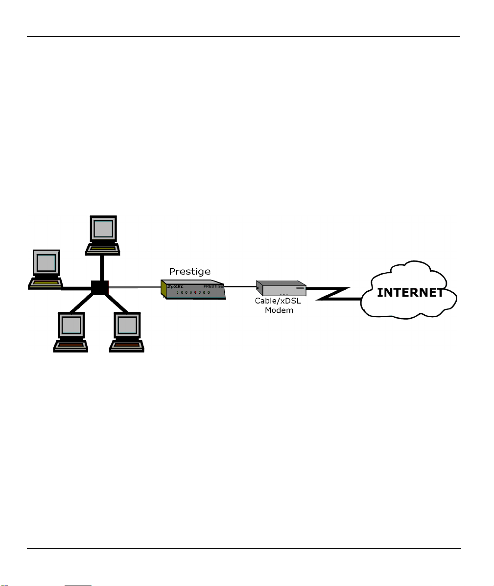
1.4 Applications for Prestige 314
1.4.1 Broadband Internet Access via Cable or DSL Modem
A cable modem or xDSL modem can connect to the Prestige 314 for broadband Internet access via Ethernet
port on the modem. A typical Internet access application is shown next.
Figure 1-1 Internet Access Application
1.5 Internet Access Configuration Checklist
The following table shows the minimum SMT menu configurations you’ll need to make (without changing
the default Prestige values) in order to access the Internet. Please also refer to the included CD which
contains HTML help on the Web Embedded Configurator, our handy web-based Internet access wizard
designed to get you up and running as soon as possible.
1-4 Getting to Know Your Prestige

Prestige 314 Broadband Sharing Gateway with 4-Port Switch
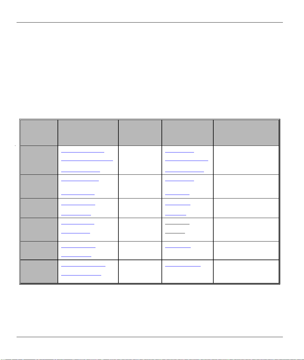
Table 1-1 Internet Access Configuration Checklist
SMT # FIELD ACTION
1 System Name This field is for identification purposes but because some ISPs check this name you
should enter your computer’s “Computer Name”.
• In Windows 95/98 click Start -> Settings -> Control Panel -> Network. Click
Identification
the
the System Name.
• In Windows 2000, click Start -> Settings-> Control Panel -> Network
Identification. Click the Identification tab, note the entry for the Computer Name
field and enter it as the System Name.
2 MAC Address:
Assigned By
4 Encapsulation
PPTP You need to know your login name, password and connection ID/Name. The latter
PPPoE You need to know your login name, password and service name. The latter may not
IP Address
Assignment
Once these key fields have been configured, you should be able to enjoy super-fast Internet access with your
Prestige!
The default is Factory Default, which is the factory assigned default MAC Address.
We recommend you choose IP Address attached on LAN and enter the IP address
of the workstation on the LAN whose MAC you are cloning.
Choose
reside in France or Austria); otherwise choose Ethernet. Choose from RR-Manager,
RR-Teltstra or RR- Toshiba if your ISP is Time Warner's RoadRunner; otherwise
choose
may not be obligatory for some ISPs, but if it is you must follow the “c:id” and
“n:name” format.
be obligatory for some ISPs.
If your ISP did not assign you a fixed IP address, select Dynamic, otherwise select
Static and enter the IP address & subnet mask in the IP address and IP Subnet
Mask fields.
PPPoE
Standard
tab, note the entry for the
if you have a dial-up connection to the Internet (or
.
Computer Name
field and enter it as
PPTP
if you
Getting to Know Your Prestige 1-5

Prestige 314 Broadband Sharing Gateway with 4-Port Switch
Hardware Installation & Initial Setup
This chapter shows you how to connect hardware and perform the initial setup.
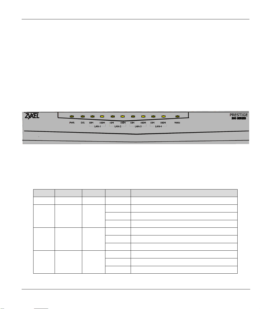
2.1 Front Panel LEDs and Rear Panel Ports
2.1.1 Front Panel LEDs
The LEDs on the front panel indicate the operational status of the Prestige.
Figure 2-1 Front Panel
Chapter 2
The following table describes the LED functions.
Table 2-1 LED Descriptions
LED FUNCTION COLOR STATUS MEANING
PWR Power Green On The Prestige is receiving power.
SYS System
10M LAN
1,2,3,4
100M
LAN
1,2,3,4
Hardware Installati on & Initia l Setup 2-1
LAN
Green Off The 10M LAN is not connected.
Orange
Off The system is not ready or failed.
On The system is ready and running.
Flashing The system is rebooting.
On The Prestige is connected to a 10M LAN.
Flashing The 10M LAN is sending/receiving packets.
Off The 100M LAN is not connected.
On The Prestige is connected to a 100Mbps LAN.
Flashing The 100M LAN is sending/receiving packets.
Prestige 314 Broadband Sharing Gateway with 4-Port Switch
LED FUNCTION COLOR STATUS MEANING
WAN WAN Green
Off The WAN Link is not ready, or has failed.
On The WAN Link is ok.
Flashing The 10M WAN link is sending/receiving packets.
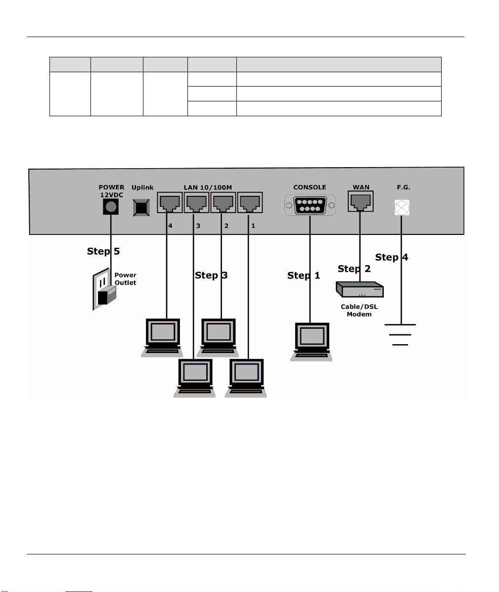
2.2 Prestige 314 Rear Panel and Connections
The following figure shows the rear panel of your Prestige 314 and the related connections.
Figure 2-2 Prestige 314 Rear Panel Connections
This section outlines how to connect your Prestige 314 to the LAN and the WAN. If you want to connect a
cable modem, you must connect the coaxial cable from your cable service to the threaded coaxial cable
connector on the back of the cable modem. Connect an xDSL modem to the xDSL wall jack.
Step 1. Connecting the Console Port
For the initial configuration of your Prestige, you need to use terminal emulator software on your computer
and connect it to the Prestige through the console port. Connect the 9-pin end of the console cable to the
console port of the Prestige and the other end (choice of 9-pin or 25-pin, depending on your computer) end
to a serial port (COM1, COM2 or other COM port) of your computer. You can use an extension RS-232
2-2 Hardware Installati on & Initia l Se tup
 Loading...