

ZyXEL Prestige 202 User Manual

Prestige 202
User's Guide
Version 2.50
(June, 2000)
ZyXEL
TOTAL INTERNET ACCESS SOLUTION


Prestige 202 ISDN Router
Copyright i
Prestige 202
ISDN Router
COPYRIGHT
Copyright © 2000 by ZyXEL Communications Corporation.
The contents of this publication may not be reproduced in any part or as a whole, transcribed, stored in a retrieval system,
translated into any language, or transmitted in any form or by any means, electronic, mechanical, magnetic, optical,
chemical, photocopying, manual, or otherwise, without the prior written permission of ZyXEL Communications
Corporation.
Published by ZyXEL Communications Corporation. All rights reserved.
DISCLAIMER
ZyXEL does not assume any liability arising out of the application or use of any products, or software described herein.
Neither does it convey any license under its patent rights nor the patent rights of others. ZyXEL further reserves the right
to make changes in any products described herein without notice. This publication is subject to change without notice.
TRADEMARKS
ZyNOS (ZyXEL Network Operating System) is a registered trademark of ZyXEL Communications, Inc. Other
trademarks mentioned in this publication are used for identification purposes only and may be properties of their
respective owners.

Prestige 202 ISDN Router
ii FCC Interference Statement
Federal Communications Commission (FCC) Interference Statement
This device complies with Part 15 of FCC rules. Operation is subject to the following two conditions:
l This device may not cause harmful interference.
l This device must accept any interference received, including interference that may cause undesired operations.
This equipment has been tested and found to comply with the limits for a Class B digital device pursuant to Part 15 of the
FCC Rules. These limits are designed to provide reasonable protection against harmful interference in a commercial
environment. This equipment generates, uses, and can radiate radio frequency energy, and if not installed and used in
accordance with the instructions, may cause harmful interference to radio communications.
If this equipment does cause harmful interference to radio/television reception, which can be determined by turning the
equipment off and on, the user is encouraged to try to correct the interference by one or more of the following measures:
1. Reorient or relocate the receiving antenna.
2. Increase the separation between the equipment and the receiver.
3. Connect the equipment into an outlet on a circuit different from that to which the receiver is connected.
4. Consult the dealer or an experienced radio/TV technician for help.
NOTICE 1
Changes or modifications not expressly approved by the party responsible for compliance could void the user's authority
to operate the equipment.
NOTICE 2
Shielded RS-232C cables are required to be used to ensure compliance with FCC Part 15, and it is the responsibility of
the user to provide and use shielded RS-232C cables.

Prestige 202 ISDN Router
Information for Canadian Users iii
Information for Canadian Users
The Industry Canada label identifies certified equipment. This certification means that the equipment meets certain
telecommunications network protective operation and safety requirements. The Industry Canada does not guarantee that
the equipment will operate to a user's satisfaction.
Before installing this equipment, users should ensure that it is permissible to be connected to the facilities of the local
telecommunications company. The equipment must also be installed using an acceptable method of connection. In some
cases, the company's inside wiring associated with a single line individual service may be extended by means of a
certified connector assembly. The customer should be aware that compliance with the above conditions may not prevent
degradation of service in some situations.
Repairs to certified equipment should be made by an authorized Canadian maintenance facility designated by the
supplier. Any repairs or alterations made by the user to this equipment, or equipment malfunctions, may give the
telecommunications company cause to request the user to disconnect the equipment.
For their own protection, users should ensure that the electrical ground connections of the power utility, telephone lines,
and internal metallic water pipe system, if present, are connected together. This precaution may be particularly important
in rural areas.
CAUTION
Users should not attempt to make such connections themselves, but should contact the appropriate electrical inspection
authority, or electrician, as appropriate.
NOTE
This digital apparatus does not exceed the Class A limits for radio noise emissions from digital apparatus set out in the
radio interference regulations of Industry Canada.

Prestige 202 ISDN Router
iv CE Marking

Prestige 202 ISDN Router
CE Statement v
Declaration of Conformity
We, the Manufacturer/Importer
ZyXEL Communications Services GmbH.
Thaliastrasse 125a/2/2/4
A-1160 Vienna – AUSTRIA
declare that the product
Prestige 202
is in conformity with
(Reference to the specification under which conformity is declared)
STANDARD STANDARD ITEM VERSION
• EN 55022
Radio disturbance characteristics – Limits and method of measurement. 1994
• EN 61000-3-2
Disturbance in supply system caused by household appliances and
similar electrical equipment “Harmonics”.
1995
• EN 61000-3-3
Disturbance in supply system caused by household appliances and
similar electrical equipment “Voltage fluctuations”.
1995
• EN 61000-4-2
Electrostatic discharge immunity test – Basic EMC Publication. 1995
• EN 61000-4-3
Radiated, radio-frequency, electromagnetic field immunity test. 1996
• EN 61000-4-4
Electrical fast transient/burst immunity test – Basic EMC Publication. 1995
• EN 61000-4-5
Surge immunity test. 1995
• EN 61000-4-6
Immunity to conducted disturbances, induced by radio-frequency fields. 1996
• EN 61000-4-8
Power Magnetic Measurement. 1993
• EN 61000-4-11
Voltage dips, short interruptions and voltage variations immunity tests. 1994

Prestige 202 ISDN Router
vi Warranty
ZyXEL Limited Warranty
ZyXEL warrants to the original end user (purchaser) that this product is free from any defects in materials or
workmanship for a period of up to two (2) years from the date of purchase. During the warranty period and upon proof of
purchase, should the product have indications of failure due to faulty workmanship and/or materials, ZyXEL will, at its
discretion, repair or replace the defective products or components without charge for either parts or labor and to whatever
extent it shall deem necessary to restore the product or components to proper operating condition. Any replacement will
consist of a new or re-manufactured functionally equivalent product of equal value, and will be solely at the discretion of
ZyXEL. This warranty shall not apply if the product is modified, misused, tampered with, damaged by an act of God, or
subjected to abnormal working conditions.
NOTE
Repair or replacement, as provided under this warranty, is the exclusive remedy of the purchaser. This warranty is in lieu
of all other warranties, express or implied, including any implied warranty of merchantability or fitness for a particular
use or purpose. ZyXEL shall in no event be held liable for indirect or consequential damages of any kind of character to
the purchaser.
To obtain the services of this warranty, contact ZyXEL's Service Center and refer to the separate Warranty Card for your
Return Material Authorization number (RMA). Products must be returned Postage Prepaid. It is recommended that the
unit be insured when shipped. Any returned products without proof of purchase or those with an out-dated warranty will
be repaired or replaced (at the discretion of ZyXEL) and the customer will be billed for parts and labor. All repaired or
replaced products will be shipped by ZyXEL to the corresponding return address, Postage Paid (USA and territories
only). If the customer desires some other return destination beyond the U.S. borders, the customer shall bear the cost of
the return shipment. This warranty gives you specific legal rights, and you may also have other rights that vary from state
to state.
Online Registration
Do not forget to register your Prestige (fast, easy online registration at www.zyxel.com for free future product updates
and information.
Prestige 202 ISDN Router
Customer Support vii
Customer Support
If you have questions about your ZyXEL product or desire assistance, contact ZyXEL Communications Corporation
offices worldwide, in one of the ways listed. Our ftp sites are also available for software and ROM upgrades.
EMAIL – SUPPORT
TELEPHONE WEB SITE
METHOD
REGION
EMAIL – SALES
FAX
FTP SITE
REGULAR MAIL
support@zyxel.com.tw
support@europe.zyxel.com
+886-3-578-3942 www.zyxel.com
www.europe.zyxel.comWORLDWIDE
sales@zyxel.com.tw +886-3-578-2439 ftp.europe.zyxel.com
ZyXEL Communications
Corp., 6 Innovation Road
II, Science-Based
Industrial Park, HsinChu,
Taiwan.
support@zyxel.com +1-714-632-0882
800-255-4101
www.zyxel.com
NORTH
AMERICA
sales@zyxel.com +1-714-632-0858 ftp.zyxel.com
ZyXEL Communications
Inc., 1650 Miraloma
Avenue, Placentia, CA
92870, U.S.A.
support@zyxel.dk +45-3955-0700 www.zyxel.dk
SCANDINAVIA
sales@zyxel.dk +45-3955-0707 ftp.zyxel.dk
ZyXEL Communications
A/S, Columbusvej 5, 2860
Soeborg, Denmark.
support@zyxel.at +43-1-4948677-0
0810-1-ZyXEL
0810-1-99935
www.zyxel.at
AUSTRIA
sales@zyxel.at +43-1-4948678 ftp.zyxel.at
NOTE: for Austrian
users with *.at domain
only!
ZyXEL Communications
Services GmbH.,
Thaliastrasse 125a/2/2/4,
A-1160 Vienna, Austria
support@zyxel.de
+49-2405-6909-0
0180-5213247
Tech Support
hotline
0180-5099935
RMA/Repair
hotline
www.zyxel.de
GERMANY
sales@zyxel.de
+49-2405-690999
ftp.europe.zyxel.com
ZyXEL Deutschland
GmbH., Adenauerstr.
20/A4, D-52146
Wuerselen, Germany.

Prestige 202 ISDN Router
viii Table of Contents
Table of Contents
Declaration of Conformity.........................................................................................................iv
Table of Contents .................................................................................................................... viii
List of Figures.......................................................................................................................... xiv
List of Tables ........................................................................................................................... xix
Preface..................................................................................................................................... xxi
Prestige Scenarios................................................................................................................ xxiv
Chapter 1 Getting to Know Your ISDN Router......................................................................1-1
1.1 Features of the Prestige .............................................................................................. 1-1
1.2 Internet Access With the Prestige................................................................................ 1-5
1.2.1 Internet Access..................................................................................................................1-5
1.2.2 LAN-to-LAN Connection..................................................................................................1-5
1.2.3 Remote Access Server .......................................................................................................1-6
Chapter 2 Hardware Installation and Initial Setup................................................................2-1
2.1 Front Panel LEDs of Prestige 202................................................................................ 2-1
2.2 Prestige 202 Rear Panel and Connections...................................................................2-2
2.3 Additional Installation Requirements............................................................................2-3
2.4 Housing.......................................................................................................................2-4
2.5 Power On Your Prestige ..............................................................................................2-4
2.6 Navigating the SMT Interface ......................................................................................2-6
2.6.1 System Management Terminal Interface Summary.............................................................2-7
2.7 Changing the System Password..................................................................................2-8
2.8 Resetting the Prestige.................................................................................................2-9
2.9 General Setup........................................................................................................... 2-10
2.10 ISDN Setup Menus.................................................................................................... 2-11
2.10.1 North American ISDN Setup Menus ................................................................................2-11
2.10.2 European (DSS1) ISDN Setup Menus..............................................................................2-15
2.11 NetCAPI.................................................................................................................... 2-17
2.11.1 CAPI...............................................................................................................................2-18
2.11.2 ISDN-DCP......................................................................................................................2-18
2.11.3 RVS-CE and RVS-COM lite............................................................................................2-18

Prestige 202 ISDN Router
Table of Contents ix
2.12 Configuring the Prestige as a NetCAPI Server........................................................... 2-18
2.12.1 Installing RVS-CE and RVS-COM lite Software ............................................................. 2-19
2.12.2 Configuring NetCAPI ..................................................................................................... 2-20
2.13 Ethernet Setup..........................................................................................................2-25
2.13.1 General Ethernet Setup.................................................................................................... 2-26
2.14 Protocol Dependent Ethernet Setup........................................................................... 2-26
Chapter 3 Internet Access.....................................................................................................3-1
3.1 Factory Ethernet Defaults............................................................................................3-1
3.2 TCP/IP Parameters .....................................................................................................3-1
3.2.1 IP Address and Subnet Mask............................................................................................. 3-1
3.2.2 Private IP Addresses .........................................................................................................3-2
3.2.3 RIP Setup.......................................................................................................................... 3-3
3.2.4 DHCP Configuration......................................................................................................... 3-3
3.3 TCP/IP Ethernet Setup and DHCP...............................................................................3-5
3.4 IP Alias........................................................................................................................3-7
3.5 IP Alias Setup.............................................................................................................. 3-8
3.6 Internet Access Configuration....................................................................................3-10
3.6.1 Sample Internet Access Configuration ............................................................................. 3-11
Chapter 4 Remote Node Configuration ................................................................................ 4-1
4.1 Remote Node Setup....................................................................................................4-1
4.1.1 Minimum Toll Period........................................................................................................4-1
4.1.2 Remote Node Profile.........................................................................................................4-2
4.1.3 Outgoing Authentication Protocol...................................................................................... 4-6
4.1.4 PPP Multilink ................................................................................................................... 4-6
4.1.5 Bandwidth on Demand......................................................................................................4-6
4.1.6 Editing PPP Options..........................................................................................................4-7
4.1.7 Remote Node Filter......................................................................................................... 4-10
Chapter 5 Remote Node TCP/IP Configuration ....................................................................5-1
5.1 LAN-to-LAN Application............................................................................................... 5-1
5.2 Remote Node Setup....................................................................................................5-3
5.2.1 Static Route Setup.............................................................................................................5-6
Chapter 6 Dial-in Server Configuration ................................................................................6-1
6.1 Remote Access Server................................................................................................6-1

Prestige 202 ISDN Router
x Table of Contents
6.2 LAN-to-LAN Server Application....................................................................................6-2
6.3 Default Dial-in User Setup ...........................................................................................6-3
6.3.1 CLID Callback Support For Dial-In Users..........................................................................6-3
6.3.2 Default Dial-in Filter .........................................................................................................6-6
6.4 Dial-In Users Setup .....................................................................................................6-6
6.4.1 Remote Access Under Windows® .....................................................................................6-9
6.4.2 CLID Authentication .......................................................................................................6-11
6.4.3 Callback..........................................................................................................................6-11
6.4.4 Configuring the Prestige for Callback With CLID............................................................6-14
Chapter 7 NAT (Network Address Translation) .................................................................... 7-1
7.1 Introduction .................................................................................................................7-1
7.1.1 Advantages of NAT...........................................................................................................7-1
7.1.2 How NAT Works ..............................................................................................................7-2
7.1.3 NAT Mapping Types.........................................................................................................7-3
7.2 NAT Application...........................................................................................................7-4
7.3 SUA (Single User Account) Versus NAT ......................................................................7-4
7.4 SMT Menus................................................................................................................. 7-5
7.4.1 NAT Setup in the Main Menu............................................................................................7-5
7.4.2 Applying NAT in the SMT Menus.....................................................................................7-5
7.5 Configuring NAT ..........................................................................................................7-7
7.5.1 Address Mapping Sets and NAT Server Sets:.....................................................................7-8
7.5.2 NAT Server Sets..............................................................................................................7-14
7.6 Examples..................................................................................................................7-17
7.6.1 Sample 1 – Internet Access Only......................................................................................7-17
7.6.2 Example 2 – Internet Access With an Inside Server..........................................................7-18
7.6.3 Example 3 – General Case...............................................................................................7-19
7.6.4 Example 4 – Non-NAT Friendly Application Programs....................................................7-22
Chapter 8 Advanced Phone Services...................................................................................8-1
8.1 Getting Started............................................................................................................ 8-2
8.1.1 Things You Need to Know Before You Start Using Supplemental Services. .......................8-2
8.2 Setting Up Supplemental Phone Service .....................................................................8-2
8.3 The Flash Key............................................................................................................. 8-2
8.4 Call Waiting.................................................................................................................8-2

Prestige 202 ISDN Router
Table of Contents xi
8.4.1 How to Use Call Waiting ..................................................................................................8-3
8.5 Three-Way Calling.......................................................................................................8-3
8.5.1 How to Use Three-Way Calling......................................................................................... 8-3
8.6 Call Transfer................................................................................................................8-4
8.6.1 How to Use Call Transfer.................................................................................................. 8-4
8.6.2 To Do a Blind Transfer: ....................................................................................................8-4
8.7 Call Forwarding...........................................................................................................8-5
8.8 Reminder Ring............................................................................................................8-5
8.9 Multiple Subscriber Number (MSN)..............................................................................8-6
8.9.1 Using MSN.......................................................................................................................8-6
8.10 Terminal Portability (Suspend/Resume).......................................................................8-6
8.10.1 How to Suspend/Resume a Phone Call .............................................................................. 8-6
Chapter 9 Filter Configuration ..............................................................................................9-1
9.1 About Filtering............................................................................................................. 9-1
9.2 Configuring a Filter Set................................................................................................9-3
9.2.1 Filter Rules Summary Menus ............................................................................................ 9-5
9.3 Configuring a Filter Rule..............................................................................................9-7
9.3.1 Filter Types and NAT .......................................................................................................9-7
9.3.2 TCP/IP Filter Rule ............................................................................................................ 9-8
9.3.3 Generic Filter Rule.......................................................................................................... 9-12
9.4 Applying Filters and Factory Defaults......................................................................... 9-14
9.4.1 Ethernet Traffic...............................................................................................................9-14
9.4.2 Remote Node Filters ....................................................................................................... 9-14
9.4.3 Default Dial-in Filter.......................................................................................................9-15
9.4.4 Sample FTP_WAN Filter Configuration..........................................................................9-15
9.4.5 Sample TELNET_WAN Filter Configuration .................................................................. 9-19
Chapter 10 SNMP (Simple Network Management Protocol)..............................................10-1
Chapter 11 Telnet Configuration and Capabilities.............................................................. 11-1
11.1 About Telnet Configuration ........................................................................................ 11-1
11.2 Telnet Under NAT ...................................................................................................... 11-2
11.3 Telnet Capabilities ..................................................................................................... 11-2
11.3.1 Single Administrator ....................................................................................................... 11-2
11.3.2 System Timeout..............................................................................................................11-2

Prestige 202 ISDN Router
xii Table of Contents
Chapter 12 System Maintenance ........................................................................................ 12-1
12.1 System Status...........................................................................................................12-2
12.1.1 System Information .........................................................................................................12-4
12.1.2 Console Port Speed..........................................................................................................12-5
12.2 Log and Trace...........................................................................................................12-5
12.2.1 Viewing Error Log ..........................................................................................................12-6
12.2.2 Syslog And Accounting...................................................................................................12-6
12.3 Diagnostic................................................................................................................. 12-8
12.4 Filename Conventions.............................................................................................12-12
12.5 Backup Configuration..............................................................................................12-13
12.6 Restore Configuration.............................................................................................. 12-14
12.7 Upload Firmware..................................................................................................... 12-16
12.7.1 Upload Router Firmware ...............................................................................................12-16
12.7.2 Uploading Router Configuration File.............................................................................12-17
12.7.3 TFTP Transfer...............................................................................................................12-18
12.7.4 Boot Module Commands ...............................................................................................12-21
12.8 Command Interpreter Mode..................................................................................... 12-22
12.9 Call Control............................................................................................................. 12-23
12.9.1 Call Control Parameters.................................................................................................12-24
12.9.2 Blacklist........................................................................................................................12-24
12.9.3 Budget Management......................................................................................................12-25
12.9.4 Call History...................................................................................................................12-26
12.10 Time and Date Setting............................................................................................. 12-27
Chapter 13 Call Scheduling................................................................................................. 13-1
13.1.1 Applying a Schedule Set..................................................................................................13-3
Chapter 14 Troubleshooting ............................................................................................... 14-1
14.1 Problems Starting Up the Prestige.............................................................................14-1
14.2 Problems With the ISDN Line .................................................................................... 14-2
14.3 Problems With the LAN Interface...............................................................................14-3
14.4 Problems Connecting to a Remote Node or ISP ........................................................14-3
14.5 Problems for Remote User to Dial-in..........................................................................14-4
Appendix A Acronyms and Abbreviations..............................................................................A
Appendix B Enhanced Syslog .................................................................................................C

Prestige 202 ISDN Router
Table of Contents xiii
Appendix C Power Adapter Specifications .............................................................................D
Index ...........................................................................................................................................E

Prestige 202 ISDN Router
xiv List of Figures
List of Figures
Figure 1-1 Internet Access Application .....................................................................................................1-5
Figure 1-2 LAN-to-LAN Connection Application .....................................................................................1-6
Figure 1-3 Remote Access ........................................................................................................................1-6
Figure 2-1 Front Panel of Prestige 202......................................................................................................2-1
Figure 2-2 Prestige 202 Rear Panel ...........................................................................................................2-2
Figure 2-3 Power-on Display for DSS1 Switches.......................................................................................2-4
Figure 2-4 Power-on Display for USA Switches........................................................................................2-5
Figure 2-5 Login Screen ...........................................................................................................................2-5
Figure 2-6 SMT Main Menu.....................................................................................................................2-7
Figure 2-7 Menu 23.1 – System Password.................................................................................................2-8
Figure 2-8 Booting Up the Prestige...........................................................................................................2-9
Figure 2-9 Menu 1 – General Setup.........................................................................................................2-10
Figure 2-10 North American ISDN Setup................................................................................................2-12
Figure 2-11 Menu 2.1 – ISDN Advanced Setup.......................................................................................2-14
Figure 2-12 Menu 2 – ISDN Setup for DSS1...........................................................................................2-16
Figure 2-13 Sample Configuration ..........................................................................................................2-19
Figure 2-14 Menu 2 – ISDN Setup..........................................................................................................2-20
Figure 2-15 Menu 2.2 – NetCAPI Setup..................................................................................................2-21
Figure 2-16 Prestige Behind a PABX.......................................................................................................2-23
Figure 2-17 ISDN Advanced Setup.........................................................................................................2-25
Figure 2-18 Loopback Test......................................................................................................................2-25
Figure 2-19 Menu 3 – Ethernet Setup......................................................................................................2-26
Figure 2-20 Menu 3.1 – General Ethernet Setup......................................................................................2-26
Figure 3-1 Menu 3.2 – TCP/IP and DHCP Ethernet Setup.........................................................................3-5
Figure 3-2 Physical Network.....................................................................................................................3-7
Figure 3-3 Partitioned Logical Networks...................................................................................................3-7
Figure 3-4 Menu 3.2 – TCP/IP and DHCP Ethernet Setup.........................................................................3-8
Figure 3-5 Menu 3.2.1 – IP Alias Setup.....................................................................................................3-9
Figure 3-6 Menu 4 – Internet Access Setup .............................................................................................3-11
Figure 4-1 Menu 11 – Remote Node Setup................................................................................................4-2

Prestige 202 ISDN Router
List of Figures xv
Figure 4-2 Menu 11.1 – Remote Node Profile...........................................................................................4-2
Figure 4-3 Menu 11.2 – Remote Node PPP Options..................................................................................4-8
Figure 4-4 Menu 11.5 – Remote Node Filter...........................................................................................4-10
Figure 5-1 TCP/IP LAN-to-LAN Application ...........................................................................................5-1
Figure 5-2 LAN 1 Setup...........................................................................................................................5-2
Figure 5-3 LAN 2 Setup...........................................................................................................................5-2
Figure 5-4 Menu 11.3 – Remote Node TCP/IP Options.............................................................................5-3
Figure 5-5 Sample IP Addresses for a TCPI/IP LAN-to-LAN Connection.................................................5-4
Figure 5-6 Sample Static Routing Topology..............................................................................................5-7
Figure 5-7 Menu 12 – IP Static Route Setup .............................................................................................5-7
Figure 5-8 Edit IP Static Route.................................................................................................................5-8
Figure 6-1 Example of Telecommuting.....................................................................................................6-2
Figure 6-2 Example of a LAN-to-LAN Server Application .......................................................................6-2
Figure 6-3 Menu 13 – Default Dial-in Setup.............................................................................................6-3
Figure 6-4 Default Dial-in Filter ...............................................................................................................6-6
Figure 6-5 Menu 14 – Dial-in User Setup .................................................................................................6-7
Figure 6-6 Edit Dial-in User .....................................................................................................................6-7
Figure 6-7 Sample Remote Access............................................................................................................6-9
Figure 6-8 Configuring Menu 13 for Remote Access...............................................................................6-10
Figure 6-9 Edit Dial-in-User for RAS.....................................................................................................6-10
Figure 6-10 LAN 1 LAN-to-LAN Application........................................................................................6-12
Figure 6-11 LAN 2 LAN-to-LAN Application ........................................................................................6-12
Figure 6-12 Testing Callback With Your Connection...............................................................................6-13
Figure 6-13 Callback With CLID Configuration......................................................................................6-14
Figure 6-14 Configuring CLID With Callback ........................................................................................6-15
Figure 6-15 Callback and CLID Connection Test.................................................................................... 6-15
Figure 7-1 How NAT Works.....................................................................................................................7-2
Figure 7-2 NAT Application .....................................................................................................................7-4
Figure 7-3 NAT in the Main Menu............................................................................................................7-5
Figure 7-4 Applying NAT for Internet Access...........................................................................................7-6
Figure 7-5 Applying NAT to the Remote Node .........................................................................................7-6
Figure 7-6 Menu 15 NAT Setup................................................................................................................7-7
Figure 7-7 Menu 15.1 – Address Mapping Sets.........................................................................................7-8

Prestige 202 ISDN Router
xvi List of Figures
Figure 7-8 SUA Address Mapping Rules...................................................................................................7-9
Figure 7-9 First Set in Menu 15.1.1.........................................................................................................7-10
Figure 7-10 Editing the First Rule in a Set...............................................................................................7-12
Figure 7-11 Editing the Second Rule in a Set...........................................................................................7-13
Figure 7-12 Multiple Servers Behind NAT ..............................................................................................7-15
Figure 7-13 Menu 15.2 – NAT Server Sets..............................................................................................7-15
Figure 7-14 Menu 15.2.1 –Multiple Server Configuration........................................................................7-16
Figure 7-15 NAT Example 1...................................................................................................................7-17
Figure 7-16 Internet Access and NAT Example.......................................................................................7-18
Figure 7-17 NAT Example 2...................................................................................................................7-18
Figure 7-18 Specifying an Inside Server..................................................................................................7-19
Figure 7-19 NAT Example 3...................................................................................................................7-20
Figure 7-20 Example 3 – Menu 15.1.1.1..................................................................................................7-21
Figure 7-21 Example 3 Final Menu 15.1.1...............................................................................................7-21
Figure 7-22 Example 3 – Menu 15.2.......................................................................................................7-22
Figure 7-23 NAT Example 4...................................................................................................................7-23
Figure 7-24 Example 4 – Menu 15.1.1.1..................................................................................................7-23
Figure 7-25 Example 4 – Menu 15.1.1 – Address Mapping Rules............................................................7-24
Figure 9-1 Filter Rule Process...................................................................................................................9-2
Figure 9-2 Outgoing Packet Filtering Process............................................................................................9-3
Figure 9-3 Menu 21 – Filter Set Configuration ..........................................................................................9-4
Figure 9-4 Menu 21.1 – Filter Rules Summary..........................................................................................9-4
Figure 9-5 Menu 21.2 – Filter Rules Summary..........................................................................................9-5
Figure 9-6 Protocol and Device Filter Sets ................................................................................................9-7
Figure 9-7 Menu 21.1.1 – TCP/IP Filter Rule............................................................................................9-8
Figure 9-8 Executing an IP Filter ............................................................................................................9-11
Figure 9-9 Menu 21.1.2 – Generic Filter Rule .........................................................................................9-12
Figure 9-10 Filtering Ethernet Traffic......................................................................................................9-14
Figure 9-11 Filtering Remote Node Traffic..............................................................................................9-15
Figure 9-12 Default Dial-in Filter............................................................................................................9-15
Figure 9-13 Menu 21 – Filter Set Configuration ......................................................................................9-16
Figure 9-14 Menu 21.3 – Filter Rules Summary......................................................................................9-17
Figure 9-15 Menu 21.3.1 – TCP/IP Filter Rule........................................................................................9-17

Prestige 202 ISDN Router
List of Figures xvii
Figure 9-16 Menu 21.3.2 – TCP/IP Filter Rule........................................................................................9-18
Figure 9-17 Menu 21.3 – Filter Rules Summary......................................................................................9-18
Figure 9-18 Menu 11.5 – Remote Node Filter .........................................................................................9-19
Figure 9-19 Sample Telnet Filter ............................................................................................................9-19
Figure 9-20 Sample Filter – Menu 21.3.1................................................................................................9-21
Figure 9-21 Sample Filter Rules Summary – Menu 21.3.........................................................................9-22
Figure 10-1 Menu 22 – SNMP Configuration .........................................................................................10-1
Figure 11-1 Telnet Configuration on a TCP/IP Network.......................................................................... 11-1
Figure 12-1 Menu 24 – System Maintenance .......................................................................................... 12-1
Figure 12-2 Menu 24.1 – System Maintenance – Status .......................................................................... 12-2
Figure 12-3 LAN Packet That Triggered Last Call ..................................................................................12-4
Figure 12-4 System Maintenance – Information......................................................................................12-4
Figure 12-5 Menu 24.2.2 – System Maintenance – Change Console Port Speed.......................................12-5
Figure 12-6 Examples of Error and Information Messages ......................................................................12-6
Figure 12-7 Menu 24.3.2 – System Maintenance – Syslog and Accounting..............................................12-6
Figure 12-8 Menu 24.4 – System Maintenance – Diagnostic .................................................................12-10
Figure 12-9 Display for a Successful Manual Call................................................................................. 12-11
Figure 12-10 Display for a Failed Authentication.................................................................................. 12-12
Figure 12-11 Backup Configuration...................................................................................................... 12-13
Figure 12-12 HyperTerminal Screen .....................................................................................................12-14
Figure 12-13 Successful Backup...........................................................................................................12-14
Figure 12-14 Restore Configuration......................................................................................................12-14
Figure 12-15 HyperTerminal Screen .....................................................................................................12-15
Figure 12-16 Successful Restoration..................................................................................................... 12-15
Figure 12-17 Menu 24.7 – System Maintenance – Upload Firmware.....................................................12-16
Figure 12-18 Menu 24.7.1 – Uploading Router Firmware......................................................................12-17
Figure 12-19 Menu 24.7.2 – System Maintenance – Upload Router Configuration File..........................12-18
Figure 12-20 Sample FTP Session ........................................................................................................ 12-20
Figure 12-21 Boot Module Commands.................................................................................................12-22
Figure 12-22 Command Mode..............................................................................................................12-22
Figure 12-23 Menu 24.9 – System Maintenance – Call Control............................................................. 12-23
Figure 12-24 Call Control Parameters................................................................................................... 12-24
Figure 12-25 Menu 24.9.2 – Blacklist...................................................................................................12-25

Prestige 202 ISDN Router
xviii List of Figures
Figure 12-26 Menu 24.9.3 – Budget Management.................................................................................12-25
Figure 12-27 Call History.....................................................................................................................12-26
Figure 12-28 System Maintenance – Time and Date Setting ..................................................................12-27
Figure 13-1 Schedule Setup ....................................................................................................................13-1
Figure 13-2 Schedule Setup ....................................................................................................................13-1
Figure 13-3 Schedule Set Setup...............................................................................................................13-2
Figure 13-4 Applying Schedule Set(s) to a Remote Node.........................................................................13-4

Prestige 202 ISDN Router
List of Tables xix
List of Tables
Table 1-1 Prestige Scenarios..................................................................................................................... xix
Table 2-1 LED Functions..........................................................................................................................2-1
Table 2-2 Main Menu Commands.............................................................................................................2-6
Table 2-3 Main Menu Summary...............................................................................................................2-7
Table 2-4 General Setup Menu Fields.....................................................................................................2-11
Table 2-5 SPIDs, Phone Numbers, Switch Types..................................................................................... 2-11
Table 2-6 North American ISDN Menu Setup Fields...............................................................................2-12
Table 2-7 NI-1 Default Feature Key Settings...........................................................................................2-14
Table 2-8 Menu 2.1 – ISDN Advanced Setup Fields................................................................................2-15
Table 2-9 Menu 2 – ISDN Setup.............................................................................................................2-17
Table 2-10 NetCAPI Setup Fields...........................................................................................................2-21
Table 3-1 DHCP Ethernet Setup Menu Fields ...........................................................................................3-6
Table 3-2 TCP/IP Ethernet Setup Menu Fields..........................................................................................3-7
Table 3-3 IP Alias Setup Menu Fields.......................................................................................................3-9
Table 3-4 Internet Account Information ..................................................................................................3-10
Table 3-5 Internet Access Setup Menu Fields.......................................................................................... 3-12
Table 4-1 Remote Node Profile Menu Fields.............................................................................................4-3
Table 4-2 BTR vs MTR for BOD..............................................................................................................4-7
Table 4-3 Remote Node PPP Options Menu Fields....................................................................................4-9
Table 5-1 TCP/IP Related Fields in Remote Node Profile..........................................................................5-4
Table 5-2 TCP/IP Remote Node Configuration .........................................................................................5-5
Table 5-3 Edit IP Static Route Menu Fields...............................................................................................5-8
Table 6-1 Remote Dial-in Users/Remote Nodes Comparison Chart ...........................................................6-1
Table 6-2 Default Dial-in Setup Fields......................................................................................................6-4
Table 6-3 Edit Dial-in User Menu Fields...................................................................................................6-7
Table 7-1 NAT Mapping Types.................................................................................................................7-3
Table 7-2 Applying NAT in Menus 4 and 11.3 ..........................................................................................7-7
Table 7-3 SUA Address Mapping Rules....................................................................................................7-9
Table 7-4 Menu 15.1.1............................................................................................................................7-11
Table 7-5 Menu 15.1.1.1 – Configuring an Individual Rule..................................................................... 7-13

Prestige 202 ISDN Router
xx List of Tables
Table 7-6 Services and Port Numbers......................................................................................................7-17
Table 8-1 Supplemental Services by Region ..............................................................................................8-1
Table 8-2 Phone Flash Commands ............................................................................................................8-5
Table 9-1 Abbreviations Used in the Filter Rules Summary Menu .............................................................9-5
Table 9-2 Abbreviations Used if Filter Type is IP ......................................................................................9-6
Table 9-3 Abbreviations Used if Filter Type is GEN..................................................................................9-6
Table 9-4 TCP/IP Filter Rule Menu Fields.................................................................................................9-8
Table 9-5 Generic Filter Rule Menu Fields..............................................................................................9-13
Table 10-1 Fields in Menu 22 (SNMP Configuration)..............................................................................10-2
Table 12-1 System Maintenance – Status Menu Fields.............................................................................12-3
Table 12-2 Fields in System Maintenance................................................................................................12-5
Table 12-3 System Maintenance Menu Syslog Parameters.......................................................................12-7
Table 12-4 System Maintenance Menu Diagnostic.................................................................................12-10
Table 12-5 Filename Conventions.........................................................................................................12-13
Table 12-6 Third-Party FTP Clients – General Fields.............................................................................12-20
Table 12-7 Call Control Parameters Fields.............................................................................................12-24
Table 12-8 Call History Fields...............................................................................................................12-26
Table 12-9 Time and Date Setting Fields...............................................................................................12-28
Table 13-1 Schedule Set Setup Fields......................................................................................................13-3
Table 14-1 Troubleshooting the Start-Up of Your Prestige .......................................................................14-1
Table 14-2 Troubleshooting the ISDN Line.............................................................................................14-2
Table 14-3 Troubleshooting the LAN Interface........................................................................................14-3
Table 14-4 Troubleshooting a Connection to a Remote Node or ISP.........................................................14-3
Table 14-5 Troubleshooting for Remote Users to Dial-in .........................................................................14-4

Prestige 202 ISDN Router
Preface xxi
Preface
About Your Prestige
Congratulations on your purchase of the Prestige 202 ISDN Router.
The Prestige 202 is a high-performance router that offers a complete Internet Access solution.
You do not need to set any switches to configure the Prestige. The user-friendly Prestige Network
Commander (PNC) is a C++ utility that allows you to manage the Prestige via a Graphical User
Interface (GUI). You can also manage the Prestige via the SMT (System Management Terminal), a
menu-driven interface that you can access from either a terminal emulator or telnet.
Please visit our web site at www.zyxel.com for the latest release notes and other information about
this product.
Setup Information
ISDN Line
1. Contact your local telephone company’s ISDN Ordering Center to find out what type of ISDN
service is available and the switch type.
2. When the telephone company installs your ISDN line, please be sure to obtain and write down the
following information for future reference:
• ISDN switch type
• ISDN telephone number(s)
• ISDN Service Profile Identifiers (SPID) number(s) (only for North America)
Supplemental services such as Call Forwarding are supported by the Prestige but must be
subscribed to separately from the telephone company.
Ethernet Setup Information
IP Address – The IP Address is the unique 32-bit number assigned to your Prestige. This address
is written in dotted decimal notation (four 8-bit numbers, between 0 and 255, separated by periods),
e.g., 192.168.1.1.

Prestige 202 ISDN Router
xxii Preface
Please note that every machine on an internet must have a unique IP address – do not assign an
arbitrary address to any machine. If you are not sure as to which IP address to assign to the
Prestige, contact your Internet Service Provider (ISP) or refer to Chapter 3 of this guide for more
details.
IP Subnet Mask – An IP address consists of two parts, the network ID and the host ID. The IP
Subnet Mask is used to specify the network ID portion of the address, expressed in dotted decimal
notation. The Prestige automatically calculates this mask based on the IP address that you assign.
Unless you have a special need for subnetting, use the default mask as calculated by the Prestige.
Related Documentation
Ø PNC Disk
More detailed information about the Prestige and examples of its use can be found in our PNC
(Prestige Network Commander – an alternative windows-based configuration wizard) Disk. This
disk contains information on configuring your Prestige for Internet Access, a General FAQ, an
Advanced FAQ, Applications Notes, Troubleshooting, Reference CI Commands as well as bundled
software.
Ø Read Me First
Our Read Me First was designed to help you get your Prestige up and running right away. It
contains a detailed easy to follow connection diagram, Prestige default settings, handy checklists
and information on setting up your PC.
Ø ZyXEL Web Page and FTP Server Site
You can access release notes for firmware upgrades and other information at ZyXEL web pages
and FTP server sites. Refer to the Customer Support page in this User’s Guide for more
information.
Ø Support Notes
More detailed information about the Prestige and examples of its use can be found in the Support
Notes accessible through the ZyXEL web page.
Ø Packing List Card
Finally, you should have a Packing List Card that lists all items that should have come with your
Prestige 202.

Prestige 202 ISDN Router
Preface xxiii
Syntax Conventions
• “Enter” means for you to type one or more characters and press the carriage return. “Select” or
“Choose” means for you to select one from the predefined choices.
• The SMT menu titles and labels are in Bold Times font. The choices of a menu item are in
Bold Arial font. A single keystroke is in Arial font and enclosed in square brackets, for
instance, [Enter] means the Enter, or carriage return key; [Esc] means the Escape key.
• For brevity’s sake, we will use “e.g.,” as a shorthand for “for instance”, and “i.e.,” as a
shorthand for “that is” or “in other words” throughout this manual.
• The Prestige 202 may also be referred to as the Prestige or the P202 from now on, in this
manual.

Prestige 202 ISDN Router
xxiv Prestige Scenarios
Prestige Scenarios
SCENARIO GO TO SECTION
To reset your Prestige 2.8.1
DHCP 3.2.4
Internet Access 3.6
LAN-to-LAN application 5.1
Remote Access under Windows® 6.4.1
Callback 6.4.3
Callback with CLID 6.4.4
To configure NAT 7.5
To apply filters 9.4
Table 1-1 Prestige Scenarios
For fast access to sample SMT menus, refer to the
following sections on how to configure the Prestige
for various possible scenarios.
Prestige 202 ISDN Router
Prestige Scenarios xxv
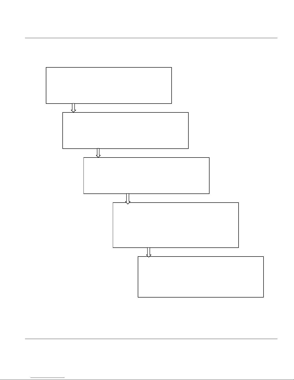
General Structure of This Manual
Getting Started (Chapters 1 and 2)
This helps you connect, install and setup your Prestige
to operate on your network.
The Internet (Chapter 3)
This shows you how to configure your Prestige for
Internet access.
Advanced Applications (Chapters 4 to 8)
This shows you how to configure remote nodes, dial-in
servers and NAT, as well as use advanced phone
services.
Management and Maintenance
(Chapters 9 to 13)
This shows you how to create/apply filters, SNMP, use
telnet, manage/maintain your system, and call
scheduling.
Troubleshooting (Chapter 14)
This provides information about solving common
problems.

I
Part I:
GETTING STARTED
Chapters 1 to 3 are structured as a step-by-step guide to help you connect, install and setup your
Prestige to operate on your network and access the Internet.


Prestige 202 ISDN Router
Getting to Know Your Router 1-1
Chapter 1
Getting to Know Your ISDN Router
This chapter covers the key features and main applications of your Prestige.
1.1 Features of the Prestige
Time and Date Setting
This new feature allows the Prestige to connect to a time server in order to synchronize its system clock when
it is booting.
Call Scheduling
This feature allows the Prestige to manage and time a call to a remote node as well as set the call duration.
NAT (Network Address Translation)
ZyXEL’s SUA (Single User Account) has now been replaced by the all new NAT support. NAT, RFC-1631)
is the translation of an Internet protocol address used within one network to a different IP address known
within another network. NAT supports five types of IP/port mapping. They are:
1. One to One: In One-to-One mode, the Prestige maps one local IP address to one global IP address.
2. Many to One: In Many-to-One mode, the Prestige maps multiple local IP addresses to one global IP
address. This is equivalent to SUA (i.e., PAT, port address translation), ZyXEL’s Single User
Account feature that previous ZyXEL routers supported (the SUA Only option in today’s routers).
3. Many to Many Overload: In Many-to-Many Overload mode, the Prestige maps the multiple local IP
addresses to shared global IP addresses.
4. Many to Many No Overload: In Many-to-Many No Overload mode, the Prestige maps each local IP
addresses to unique global IP addresses.
5. Server: This type allows us to specify multiple inside servers of different types behind the NAT.
ZyXEL is also proud to announce that NetMeeting is supported for both incoming and outgoing calls. For
outgoing calls, there is no special configuration needed but for incoming calls, set the NetMeeting server to
ports 1503 and 1720.
SNMP (Simple Network Management Protocol – version 1)
SNMP, a member of the TCP/IP protocol suite, allows you to exchange management information between
network devices. Your Prestige supports SNMP agent functionality that allows a manager station to manage
and monitor the Prestige through the network.
NOTE: SNMP is only available if TCP/IP is configured on your Prestige.
 Loading...