

ZyXEL PMG5318-B20B User Manual

Quick Start Guide
PMG5318-B20B
Wireless N GPON HGU with 4-port GbE Switch
Version 1.00
Edition 1, 2/2016
User’s Guide
Default Login Details
LAN IP Address
User Name
Password
www.zyxel.com
http://192.168.1.1
admin
1234
Copyright © 2016 ZyXEL Communications Corporation

IMPORTANT!
READ CAREFULLY BEFORE USE.
KEEP THIS GUIDE FOR FUTURE REFERENCE.
Screenshots and graphics in this book may differ slightly from your product due to differences in
your product firmware or your computer operating system. Every effort has been made to ensure
that the information in this manual is accurate.
Related Documentation
•Quick Start Guide
The Quick Start Guide shows how to connect the GPON Device and get up and running right
away.
PMG5318-B20B User’s Guide
2

Table of Contents
Table of Contents
Chapter 1
Introduction...........................................................................................................................................8
1.1 Managing the GPON Device ...............................................................................................................8
1.2 Good Habits for Managing the GPON Device .....................................................................................8
1.3 Applications for the GPON Device ......................................................................................................8
1.3.1 Triple Play ..................................................................................................................................8
1.3.2 Internet Access ..........................................................................................................................9
1.3.3 VoIP Features ............................................................................................................................ 9
1.4 LEDs (Lights) ......................................................................................................................................9
1.5 Reset Button .....................................................................................................................................11
1.6 WLAN Button .................................................................................................................................... 11
1.7 WPS Button ....................................................................................................................................... 11
Chapter 2
The Web Configurator........................................................................................................................12
2.1 Accessing the Web Configurator .......................................................................................................12
2.2 Web Configurator Main Screen .........................................................................................................12
2.2.1 Title Bar ................................................................................................................................... 13
2.2.2 Navigation Panel .....................................................................................................................13
2.2.3 Main Window ...........................................................................................................................13
Chapter 3
Device Info...........................................................................................................................................14
3.1 Device Info Summary ........................................................................................................................14
3.2 WAN Info ...........................................................................................................................................15
3.3 LAN Statistics ....................................................................................................................................16
3.4 WAN Statistics ...................................................................................................................................17
3.5 Route Info .......................................................................................................................................... 18
3.6 ARP Info ............................................................................................................................................19
3.7 DHCP Leases ...................................................................................................................................20
Chapter 4
WAN .....................................................................................................................................................21
4.1 GPON Layer2 Interface .....................................................................................................................21
4.1.1 Layer-2 GPON Interface Configuration ...................................................................................21
4.2 WAN Service .....................................................................................................................................22
4.2.1 WAN Service Configuration .....................................................................................................23
PMG5318-B20B User’s Guide
3

Table of Contents
Chapter 5
LAN ......................................................................................................................................................36
5.1 LAN Setup .........................................................................................................................................36
5.1.1 Add DHCP Static IP Lease ......................................................................................................37
5.2 IPv6 LAN Auto Configuration ............................................................................................................38
Chapter 6
Network Address Translation (NAT)..................................................................................................41
6.1 Virtual Servers ...................................................................................................................................41
6.1.1 Virtual Servers Add .................................................................................................................42
6.2 Port Triggering ..................................................................................................................................43
6.2.1 Add Port Triggering Rule ........................................................................................................ 45
6.3 DMZ Host ..........................................................................................................................................46
Chapter 7
Security................................................................................................................................................47
7.1 Outgoing IP Filtering .........................................................................................................................48
7.1.1 Creating Outgoing Filtering Rules .........................................................................................48
7.2 Incoming IP Filtering ......................................................................................................................... 49
7.2.1 Creating Incoming Filtering Rules .........................................................................................50
7.3 MAC Filtering Setup ..........................................................................................................................52
7.3.1 Creating MAC Filtering Rules ................................................................................................53
Chapter 8
Parental Control..................................................................................................................................54
8.1 Time Restriction ................................................................................................................................54
8.1.1 Add a Time Restriction Rule ....................................................................................................54
8.2 URL Filter ..........................................................................................................................................55
8.2.1 Add a URL Filter Rule .............................................................................................................. 56
Chapter 9
Routing ...............................................................................................................................................57
9.1 Default Gateway ................................................................................................................................57
9.2 Static Route ....................................................................................................................................... 58
9.2.1 Add Static Route ......................................................................................................................58
9.3 Policy Routing ...................................................................................................................................59
9.3.1 Add Policy Routing .................................................................................................................. 60
9.4 RIP ....................................................................................................................................................60
Chapter 10
DNS ......................................................................................................................................................62
10.1 DNS Server ..................................................................................................................................... 62
10.2 Dynamic DNS .................................................................................................................................. 63
PMG5318-B20B User’s Guide
4

Table of Contents
10.2.1 Dynamic DNS Add ................................................................................................................64
Chapter 11
UPnP ....................................................................................................................................................65
11.1 UPnP ...............................................................................................................................................65
Chapter 12
DNS Proxy...........................................................................................................................................66
12.1 DNS Proxy ......................................................................................................................................66
Chapter 13
Storage Service...................................................................................................................................67
13.1 Storage Service ...............................................................................................................................67
13.2 Storage Device Info ........................................................................................................................67
13.3 User Accounts .................................................................................................................................68
13.3.1 Add Storage Service User Account .......................................................................................69
Chapter 14
Remote Management..........................................................................................................................70
14.1 Remote Management ......................................................................................................................70
Chapter 15
Interface Grouping..............................................................................................................................73
15.1 Interface Grouping ..........................................................................................................................73
15.1.1 Interface Group Configuration ...............................................................................................74
Chapter 16
IP Tunnel..............................................................................................................................................76
16.1 IPv6inIPv4 (6RD) ............................................................................................................................76
16.1.1 IPv6inIPv4 Configuration .......................................................................................................77
16.2 IPv4inIPv6 (Dual Stack Lite) ............................................................................................................ 78
16.2.1 IPv4inIPv6 Configuration .......................................................................................................79
Chapter 17
Certificates..........................................................................................................................................81
17.1 Local Certificates .............................................................................................................................81
17.1.1 Create Certificate Request ...................................................................................................82
17.1.2 Load Signed Certificate ........................................................................................................83
17.2 Trusted CA ....................................................................................................................................84
17.2.1 View Trusted CA Certificate ...................................................................................................84
17.2.2 Import Trusted CA Certificate ................................................................................................ 85
Chapter 18
Multicast ..............................................................................................................................................87
PMG5318-B20B User’s Guide
5

Table of Contents
18.1 Multicast ..........................................................................................................................................87
Chapter 19
Wireless...............................................................................................................................................89
19.1 Wireless Basic ................................................................................................................................ 89
19.2 Wireless Security ............................................................................................................................90
19.3 Wireless MAC Filter ........................................................................................................................93
19.3.1 Wireless MAC Filter Add ...................................................................................................93
19.4 Wireless Bridge ............................................................................................................................... 94
19.5 Wireless Advanced .........................................................................................................................95
19.6 Wireless Station Info .......................................................................................................................99
Chapter 20
Voice ..................................................................................................................................................100
20.1 SIP Global Parameters ................................................................................................................ 100
20.2 SIP Service Provider .....................................................................................................................100
20.2.1 Dial Plan Rules .................................................................................................................... 103
20.3 SIP Service Provider Advanced Settings ......................................................................................104
20.4 SIP Debug Settings .......................................................................................................................106
Chapter 21
Diagnostics .......................................................................................................................................108
21.1 Diagnostics ...................................................................................................................................108
21.2 Ping/TraceRoute/Nslookup ........................................................................................................... 108
Chapter 22
Settings..............................................................................................................................................110
22.1 Backup Configuration Using the Web Configurator ...................................................................... 110
22.2 Restore Configuration Using the Web Configurator ...................................................................... 110
22.3 Restoring Factory Defaults ............................................................................................................ 111
Chapter 23
Logs ..................................................................................................................................................112
23.1 Logs .............................................................................................................................................. 112
23.1.1 What You Need To Know .....................................................................................................112
23.2 System Log ................................................................................................................................... 113
23.3 System Log Configuration ............................................................................................................. 113
23.4 Security Log .................................................................................................................................. 114
Chapter 24
SNMP .................................................................................................................................................116
24.1 SNMP Agent ................................................................................................................................. 116
PMG5318-B20B User’s Guide
6

Table of Contents
Chapter 25
TR-069 Client.....................................................................................................................................118
25.1 TR-069 Client ................................................................................................................................ 118
Chapter 26
Internet Time.....................................................................................................................................120
26.1 Internet Time ................................................................................................................................. 120
Chapter 27
User Passwords................................................................................................................................121
27.1 User Passwords ............................................................................................................................121
Chapter 28
GPON Password ...............................................................................................................................122
28.1 GPON Password ...........................................................................................................................122
Chapter 29
Update Software................................................................................................................................123
29.1 Update Software ...........................................................................................................................123
Chapter 30
Reboot ...............................................................................................................................................125
30.1 Restart Using the Web Configurator .............................................................................................125
Chapter 31
Troubleshooting................................................................................................................................126
31.1 Overview .......................................................................................................................................126
31.2 Power, Hardware Connections, and LEDs ....................................................................................126
31.3 GPON Device Access and Login ..................................................................................................127
31.4 Internet Access .............................................................................................................................128
31.5 Phone Calls and VoIP ...................................................................................................................129
Appendix A Customer Support ........................................................................................................130
Appendix B Legal Information..........................................................................................................136
Index ..................................................................................................................................................144
PMG5318-B20B User’s Guide
7

CHAPTER 1
Introduction
The PMG5318-B20B combines a fiber optic (GPON) router with a built-in switch. Its voice over IP
(VoIP) capabilities allow you to use a traditional analog telephone to make Internet phone calls. The
GPON Device connects to the ISP’s OLT (Optical Line Terminal).
1.1 Managing the GPON Device
Use the GPON Device’s built-in Web Configurator to manage it. You can connect to it using a web
browser. See Section 2.1 on page 12 for details.
1.2 Good Habits for Managing the GPON Device
Do the following things regularly to make the GPON Device more secure and to manage the GPON
Device more effectively.
• Change the password. Use a password that’s not easy to guess and that consists of different
types of characters, such as numbers and letters.
• Write down the password and put it in a safe place.
• Back up the configuration (and make sure you know how to restore it). Restoring an earlier
working configuration may be useful if the device becomes unstable or even crashes. If you
forget your password, you will have to reset the GPON Device to its factory default settings. If
you backed up an earlier configuration file, you would not have to totally re-configure the GPON
Device. You could simply restore your last configuration.
1.3 Applications for the GPON Device
Here are some example uses for which the GPON Device is well suited.
1.3.1 Triple Play
The ISP may provide “triple play” service to the GPON Device. This allows you to take advantage of
such features as broadband Internet access, Voice over IP telephony, and streaming video/audio
media, all at the same time with no noticeable loss in bandwidth.
PMG5318-B20B User’s Guide
8

1.3.2 Internet Access
Internet
LAN
Internet
PSTN
Your GPON Device provides shared Internet access by connecting a fiber optic line provided by the
ISP to the PON port.
Figure 1 GPON Device’s Router Features
1.3.3 VoIP Features
You can register up to 2 SIP (Session Initiation Protocol) accounts and use the GPON Device to
make and receive VoIP telephone calls:
Chapter 1 Introduction
Figure 2 GPON Device’s VoIP Features
Calls via a VoIP service provider - the GPON Device sends your call to a VoIP service provider’s SIP
server which forwards your calls to either VoIP or PSTN phones.
1.4 LEDs (Lights)
The following graphic displays the top panel LEDs.
PMG5318-B20B User’s Guide
9

Chapter 1 Introduction
Figure 3 LEDs
All of the LEDs are off if the GPON Device is not receiving power.
Table 1 LED Descriptions
LED COLOR STATUS DESCRIPTION
POWER Green On The GPON Device is receiving power and ready for use.
Blinking The GPON Device is self-testing.
Red On The GPON Device detected an error while self-testing, or there is a device
malfunction.
Off The GPON Device is not turned on.
PON Green On The GPON Device has a PON line connection.
Blinking The GPON Device is downloading software.
Orange On The GPON Device’s PON port is physically connected but the OLT did not
provision the GPON Device.
Red On The GPON Device’s PON port is not connected. The optical transceiver may
Off The GPON Device has lost the PON link
INTERNET Green On The GPON Device has an IP connection but no traffic.
Blinking The GPON Device is sending or receiving IP traffic.
Off The GPON Device does not have an IP connection.
Red On The GPON Device attempted to get an IP address but failed.
USB 2~1 Green On The GPON Device recognizes a USB connection through the USB slot.
Blinking The GPON Device is sending or receiving data to or from the USB device
Off The GPON Device does not detect a USB connection through the USB slot.
ETHERNET
4~1
PHONE
2~1
Green On The GPON Device has an Ethernet connection with another device (such as
Blinking The GPON Device is sending/receiving data to/from the LAN through this
Off The GPON Device does not have an Ethernet connection through this port.
Green On A SIP account is registered for the phone port.
Blinking A telephone connected to the phone port has its receiver off the hook or
Amber On The SIP account registered for the phone port has a voice message.
Blinking A telephone connected to the phone port has its receiver off the hook and
Off The phone port does not have a SIP account registered or the GPON Device
have malfunctioned or the fiber cable may not be connected or may be
broken or damaged enough to break the PON connection.
connected to it.
a computer) on the Local Area Network (LAN) through this port.
port.
there is an incoming call.
the SIP account registered for the phone port has a voice message.
is turned off.
PMG5318-B20B User’s Guide
10

Table 1 LED Descriptions (continued)
LED COLOR STATUS DESCRIPTION
Wi-Fi
2.4G
Green On The wireless network is activated.
Orange Blinking The GPON Device is setting up a WPS connection.
1.5 Reset Button
If you forget your password or cannot access the web configurator, you will need to use the RESET
button at the back of the device to reload the factory-default configuration file. This means that you
will lose all configurations that you had previously and the password will be reset to the default.
1 Make sure the POWER LED is on (not blinking).
2 To set the device back to the factory default settings, press the RESET button for more than 5
seconds or until the POWER LED begins to blink and then release it. When the POWER LED begins
to blink, the defaults have been restored and the device restarts.
Chapter 1 Introduction
Blinking The GPON Device is communicating with other wireless clients.
Off The wireless network is not activated.
1.6 WLAN Button
Press the WLAN button on the back of the device for more than 1 second to enable or disable the
wireless LAN.
1.7 WPS Button
Use the WPS button on the back of the device to activate WPS in order to quickly set up a wireless
network with strong security.
1 Make sure the POWER LED is on (not blinking).
2 Press the WPS button for more than 1 second to activate WPS.
3 Press the WPS button on a compatible device within 2 minutes of pressing the button on the GPON
Device. The WLAN LED should flash in orange while the GPON Device sets up a WPS connection
with the other wireless device.
4 Once the connection is successfully made, the WLAN LED shines green.
PMG5318-B20B User’s Guide
11

CHAPTER 2
The Web Configurator
The web configurator is an HTML-based management interface that allows easy device setup and
management via Internet browser. Use Internet Explorer 8.0 and later or Firefox 23.0.0 and later
versions. The recommended screen resolution is 1024 by 768 pixels.
In order to use the web configurator you need to allow:
• Web browser pop-up windows from your GPON Device. Web pop-up blocking is enabled by
default in Windows XP SP (Service Pack) 2.
• JavaScript (enabled by default).
• Java permissions (enabled by default).
2.1 Accessing the Web Configurator
1 Make sure your GPON Device is properly connected (see the Quick Start Guide for details).
2 Launch your web browser.
3 Type the default device address shown on the cover page of this User’s Guide as the URL.
4 A password screen displays. Enter the default user name and password shown on the cover page of
this User’s Guide password and click OK.
Figure 4 Password Screen
Note: For security reasons, the GPON Device automatically logs you out if you do not use
the web configurator for an extended period of time. If this happens, log in again.
2.2 Web Configurator Main Screen
The main screen is divided into the title bar (A), navigation panel (B), and main window (C).
PMG5318-B20B User’s Guide
12
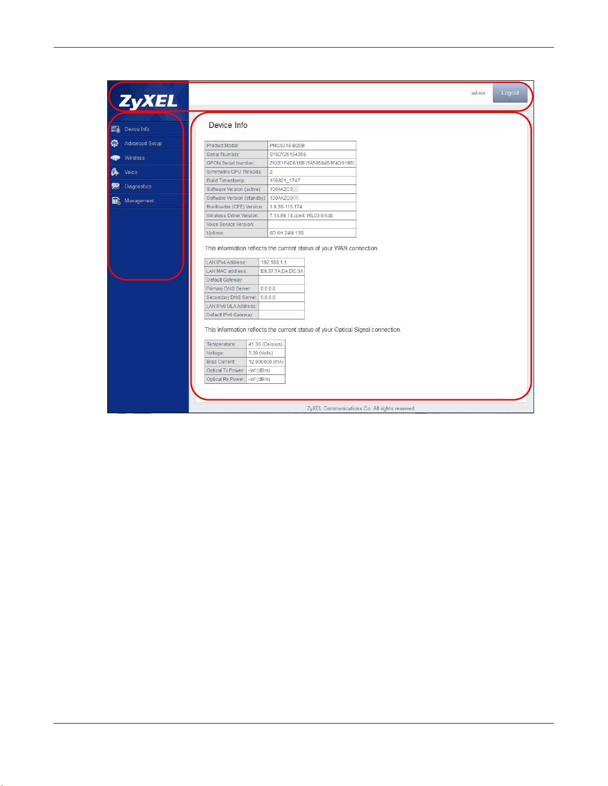
Figure 5 Main Screen
B
C
A
Chapter 2 The Web Configurator
2.2.1 Title Bar
The title bar identifies the logged in account and provides the Logout button in the upper right
corner. Click the Logout button to log out of the web configurator
2.2.2 Navigation Panel
Use the menu items on the navigation panel to open screens to configure GPON Device features.
2.2.3 Main Window
The main window displays information and configuration fields. It is discussed in the rest of this
document.
Right after you log in, the Device Info screen is displayed. See Chapter 3 on page 14 for more
information about the Device Info screen.
.
PMG5318-B20B User’s Guide
13
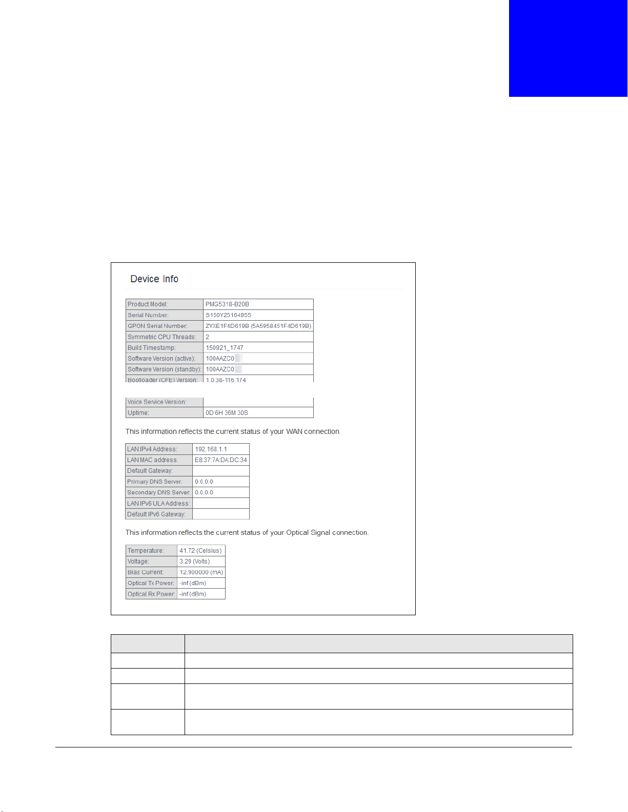
3.1 Device Info Summary
Click Device Info > Summary to open this screen with general device and WAN connection status
information.
Figure 6 Device Info Summary
CHAPTER 3
Device Info
Table 2 Device Info Summary
LABEL DESCRIPTION
Product Model This field displays the GPON Device’s model name.
Serial Number This field displays the GPON Device’s serial number.
GPON Serial
Number
Symmetric CPU
Threads
This field displays the serial number the GPON Device uses for its GPON connection.
This field displays the number of threads in the GPON Device’s CPU.
PMG5318-B20B User’s Guide
14

Chapter 3 Device Info
Table 2 Device Info Summary (continued)
LABEL DESCRIPTION
Build
Timestamp
Software
Version (active)
Software
Version
(standby)
Bootloader
(CFE) Version
Wireless Driver
Version
Voice Service
Version
Uptime This field displays how long the GPON Device has been running since it last started up.
LAN IPv4
Address
LAN MAC
address
Default
Gateway
Primary DNS
Server
Secondary DNS
Server
LAN IPv6 ULA
Address
Default IPv6
Gateway
Date/Time This field displays the GPON Device’s current day of the week, month, hour, minute, second,
Temperature This displays the optical transceiver’s temperature in Celsius. The normal range is 0-70
Voltage This displays the optical transceiver’s voltage in Volts. The normal range is 3.13-3.47 Volts.
Bias Current This displays the optical transceiver’s bias current in mA. The normal range is 4-50 mA.
Optical Tx
Power
Optical Rx
Power
This field displays the date (YYMMDD) and time (HHMM) of the firmware in the GPON
Device.
This field displays the version of the firmware the GPON Device is currently using.
This field displays the version of the GPON Device’s backup firmware.
This field displays the version of bootloader the GPON Device is using.
This field displays the version of the driver for the GPON Device’s wireless chipset.
This field displays the version of the VoIP software the GPON Device is using.
This field displays the current IP address of the GPON Device in the LAN.
This shows the LAN Ethernet adapter MAC (Media Access Control) address of your GPON
Device.
This field displays the IP address of the gateway through which the GPON Device sends
traffic unless it matches a static route.
The GPON Device tries this DNS server first when it needs to resolve a domain name into a
numeric IP address.
The GPON Device uses this DNS server first when it needs to resolve a domain name into a
numeric IP address if the primary DNS server does not respond.
This field displays the current unique local address (ULA). This is a unique IPv6 address for
use in private networks but not routable in the global IPv6 Internet.
This field displays the IPv6 address of the gateway through which the GPON Device sends
IPv6 traffic unless it matches a static route.
and year.
degrees.
This displays the optical transceiver’s optical transmitting power in dBm.
This displays the optical transceiver’s optical receiving power in dBm. The normal range is 28 to -8 dBm.
3.2 WAN Info
Click Device Info > WAN to open this screen which lists the GPON Device’s WAN connections and
their status.
PMG5318-B20B User’s Guide
15

Chapter 3 Device Info
Figure 7 WAN Info
Table 3 WAN Info
LABEL DESCRIPTION
Interface This shows the name of the WAN interface. veip0 stands for a virtual Ethernet card and is
the foundation for veip0/* which are virtual WAN interfaces of the physical GPON line. The
ppp0.* indicates a PPP connection.
The number after the dot (.) represents the VLAN ID number assigned to traffic sent
through this connection. The number after the underscore (_) represents the index number
of connections through the same interface.
(null) means the entry is not valid.
Description This is the service name of this connection.
Type This shows the method of encapsulation used by this connection (IP over Ethernet, PPP over
Ethernet, or bridging).
VlanMuxID This indicates the VLAN ID number assigned to traffic sent through this connection. This
displays N/A when there is no VLAN ID number assigned.
IPv6 This displays whether or not IPv6 is enabled on the interface.
Igmp Pxy This shows whether IGMP (Internet Group Multicast Protocol) proxy is activated or not for
Igmp Src Enbl This shows whether IGMP source enable is activated or not for this connection. IGMP source
MLD Pxy This shows whether Multicast Listener Discovery (MLD) proxy is activated or not for this
MLD Src Enbl This shows whether MLD source enable is activated or not for this connection. MLD source
NAT This shows whether NAT is activated or not for this interface. NAT is not available when the
Firewall This shows whether the firewall is activated or not for this interface.
Status This displays the connection state or Unconfigured if the interface has not yet been
IPv4 Address This displays the interface’s current IPv4 address if it has one.
IPv6 Address This displays the interface’s current IPv6 address if it has one.
this connection. IGMP is not available when the connection uses the bridging service.
enable has the GPON Device add routing table entries based on the IGMP traffic.
connection. MLD is not available when the connection uses the bridging service.
enable has the GPON Device add routing table entries based on the MLD traffic.
connection uses the bridging service.
configured.
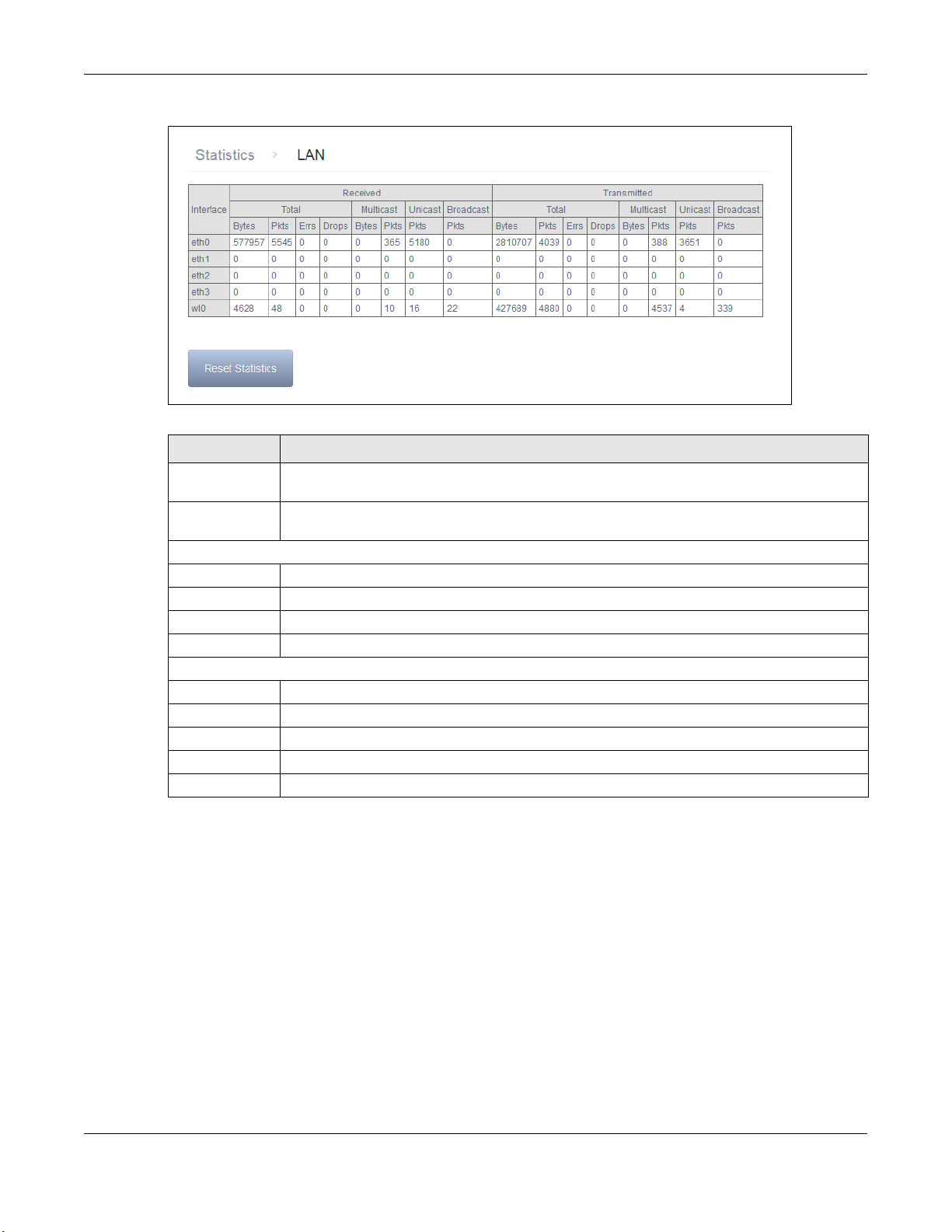
3.3 LAN Statistics
Click Device Info > Statistics > LAN to open this screen of traffic statistics counters for the
GPON Device’s wired and wireless LAN interfaces. Use the button to clear the counters.
PMG5318-B20B User’s Guide
16
Chapter 3 Device Info
Figure 8 LAN Statistics
Table 4 LAN Statistics
LABEL DESCRIPTION
Interface These fields identify the LAN interfaces. eth0 ~ eth3 represent the ethernet LAN ports 1 ~
Received /
Tra nsmi tted
Received
Bytes This indicates the number of bytes received on this interface.
Pkts This indicates the number of packets received on this interface.
Errs This indicates the number of frames with errors received on this interface.
Drops This indicates the number of received packets dropped on this interface.
Tra nsmi tted
Bytes This indicates the number of bytes transmitted on this interface.
Pkts This indicates the number of transmitted packets on this interface.
Errs This indicates the number of frames with errors transmitted on this interface.
Drops This indicates the number of outgoing packets dropped on this interface.
Reset Statistics Click this to clear the screen’s statistics counters.
4. wlo represents the wireless LAN interface.
These fields display the number of bytes, packets, error packets, and dropped packets for
each interface.
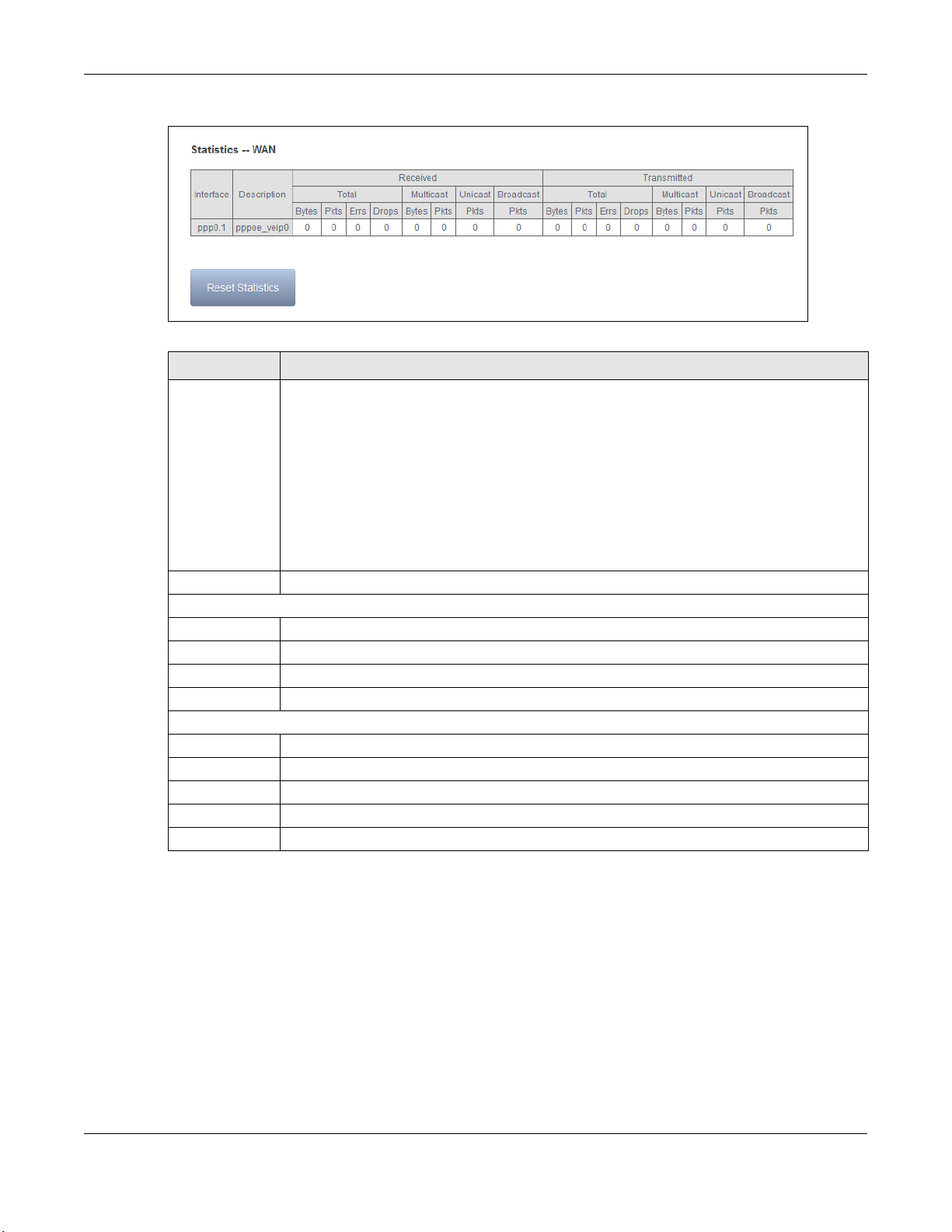
3.4 WAN Statistics
Click Device Info > Statistics > WAN Service to display the total, multicast, unicast, and
broadcast traffic statistics counters for the GPON Device’s WAN interfaces. Use the button to clear
the counters.
PMG5318-B20B User’s Guide
17
Chapter 3 Device Info
Figure 9 WAN Statistics
Table 5 WAN Statistics
LABEL DESCRIPTION
Interface This shows the name of the WAN interface used by this connection.
veip0 stands for a virtual Ethernet card and is the foundation for veip0/* which are virtual
WAN interfaces of the physical GPON line. The ppp0.* indicates a PPP connection.
eth0 ~ eth3 represent the Ethernet LAN ports 1 ~ 4 and are the foundation for eth0/*
which are virtual WAN interfaces of the physical Gigabit Ethernet line.
The number after the dot (.) represents the VLAN ID number assigned to traffic sent
through this connection. The number after the underscore (_) represents the index number
of connections through the same interface.
Description This is the service name of this connection.
Received
Bytes This indicates the number of bytes received on this interface.
Pkts This indicates the number of packets received on this interface.
Errs This indicates the number of frames with errors received on this interface.
Drops This indicates the number of received packets dropped on this interface.
Tra nsmi tted
Bytes This indicates the number of bytes transmitted on this interface.
Pkts This indicates the number of transmitted packets on this interface.
Errs This indicates the number of frames with errors transmitted on this interface.
Drops This indicates the number of outgoing packets dropped on this interface.
Reset Statistics Click this to clear the screen’s statistics counters.
3.5 Route Info
Click Device Info > Route to display the GPON Device’s IPv4 and IPv6 routing tables.
(null) means the entry is not valid.
PMG5318-B20B User’s Guide
18
Chapter 3 Device Info
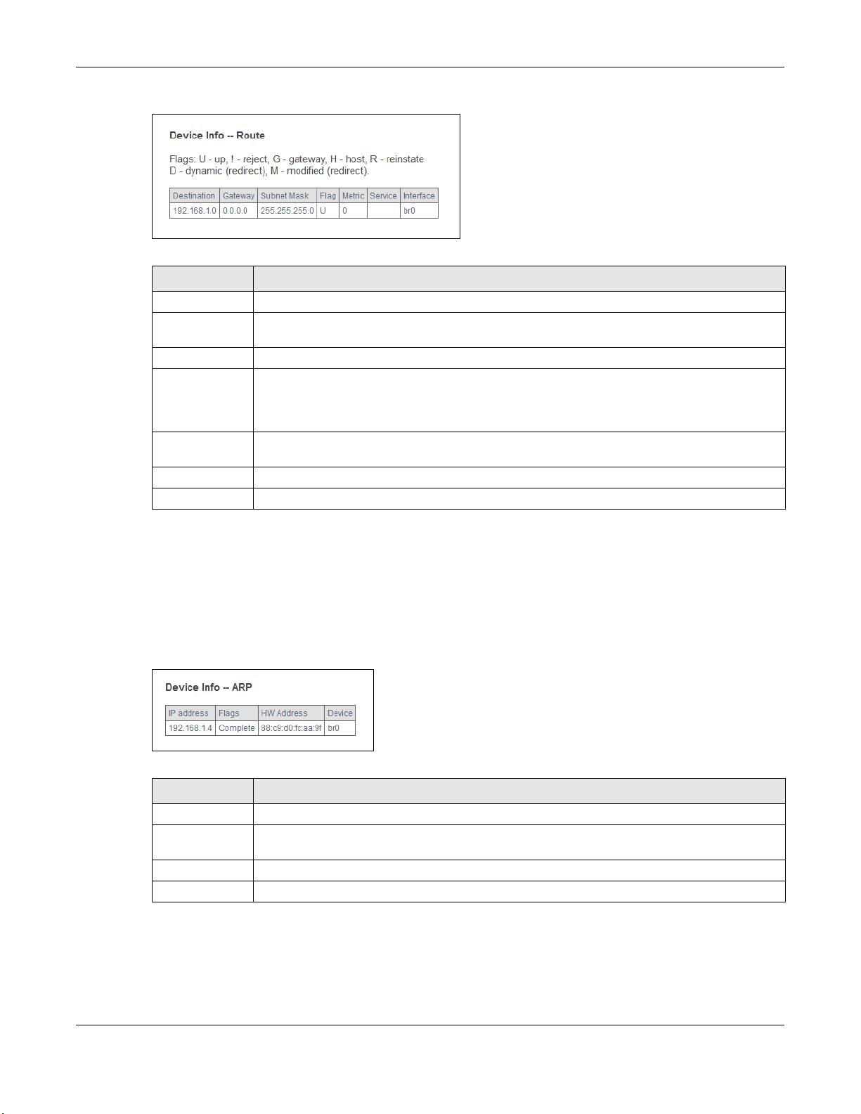
Figure 10 Route Info
Table 6 Route Info
LABEL DESCRIPTION
Destination This displays the IP address to which this entry applies.
Gateway This displays the gateway the GPON Device uses to send traffic to the entry’s destination
address.
Subnet Mask This displays the subnet mask of the destination net.
Flag This displays whether the route is up (U), the GPON Device drops packets for this
destination (!), the route uses a gateway (G), the target is in the neighbor cache (C), the
target is a host (H), reinstate route for dynamic routing (R), the route was dynamically
installed by redirect (D), or modified from redirect (M).
Metric The metric represents the “cost” of transmission for routing purposes. IP routing uses hop
count as the measurement of cost, with a minimum of 1 for directly-connected networks.
Service The name of a specific service to which the route applies if one is specified.
Interface The interface through which this route sends traffic.
3.6 ARP Info
Click Device Info > ARP to display the GPON Device’s IPv4 Address Resolution Protocol and IPv6
neighbor tables. This screen lists the IP addresses the GPON Device has mapped to MAC addresses.
Figure 11 ARP Info
Table 7 ARP Info
LABEL DESCRIPTION
IP address The learned IP address of a device connected to one of the system’s ports.
Flags Static - static entry, Dynamic - dynamic entry that is not yet complete, Complete -
HW Address The MAC address of the device with the listed IP address.
Device The interface through which the GPON Device sends traffic to the device listed in the entry.
dynamic entry that is complete.
PMG5318-B20B User’s Guide
19

3.7 DHCP Leases
Click Device Info > DHCP to display the GPON Device’s list of IP address currently leased to DHCP
clients.
Figure 12 DHCP Leases
Table 8 DHCP Leases
LABEL DESCRIPTION
Hostname This field displays the name used to identify this device on the network (the computer
name). The GPON Device learns these from the DHCP client requests. “None” shows here
for a static DHCP entry.
MAC Address This field displays the MAC address to which the IP address is currently assigned or for
which the IP address is reserved. Click the column’s heading cell to sort the table entries by
MAC address. Click the heading cell again to reverse the sort order.
IP Address This field displays the IP address currently assigned to a DHCP client or reserved for a
specific MAC address. Click the column’s heading cell to sort the table entries by IP address.
Click the heading cell again to reverse the sort order.
Expires In This field displays how much longer the IP address is leased to the DHCP client.
Chapter 3 Device Info
PMG5318-B20B User’s Guide
20
4.1 GPON Layer2 Interface
The GPON Device must have a layer-2 interface to allow users to use the GPON port to access the
Internet. Log into the GPON Device’s Web Configurator and click Advanced Setup > Layer2
Interface > GPON Interface to manage the GPON layer-2 interface.
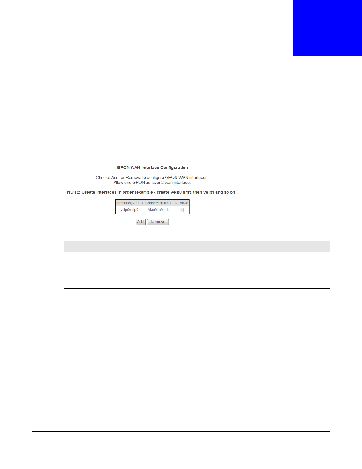
Figure 13 GPON Interface
CHAPTER 4
WAN
Table 9 GPON Interface
LABEL DESCRIPTION
Interface/(Name) The name of a configured layer-2 interface. veip0 stands for a virtual Ethernet card and
Connection Mode This shows the connection mode of the layer-2 interface.
Remove Select an interface and click the Remove button to delete it. You cannot remove a layer-
Add Click this button to create a new layer-2 interface. You can only have one GPON layer 2
is the foundation for veip0/* which are virtual WAN interfaces of the physical GPON line.
The number after the dot (.) represents the VLAN ID number assigned to traffic sent
through this connection. The number after the underscore (_) represents the index
number of connections through the same interface.
2 interface when a WAN service is associated with it.
interface at a time.
4.1.1 Layer-2 GPON Interface Configuration
Click the Add button in the Layer2 Interface: GPON Interface screen to open the following
screen. Select the GPON port and click Apply/Save to create a new layer-2 interface.
PMG5318-B20B User’s Guide
21
Chapter 4 WAN
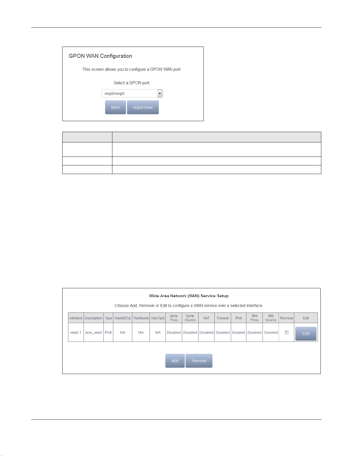
Figure 14 GPON Interface Configuration
Table 10 GPON Interface Configuration
LABEL DESCRIPTION
Select a GPON port Select a GPON port. veip0 stands for a virtual Ethernet card and is the foundation for
veip0/* which are virtual WAN interfaces of the physical GPON line.
Back Click this button to return to the previous screen without saving any changes.
Apply/Save Click this button to save your changes and go back to the previous screen.
4.2 WAN Service
Use this screen to change your GPON Device’s WAN settings. Click Advanced Setup > WAN
Service. The summary table shows you the configured WAN services (connections) on the GPON
Device.
To use NAT, firewall or IGMP proxy in the GPON Device, you need to configure a WAN connection
with PPPoE or IPoE.
Note: When a layer-2 interface is in VLAN MUX Mode, you can configure up to five WAN
services on the GPON Device.
Figure 15 WAN Service
PMG5318-B20B User’s Guide
22

Chapter 4 WAN
Table 11 WAN Service
LABEL DESCRIPTION
Interface This shows the name of the interface used by this connection.
veip0 stands for a virtual Ethernet card and is the foundation for veip0/* which are virtual
WAN interfaces of the physical GPON line. The ppp0.* indicates a PPP connection.
The number after the dot (.) represents the VLAN ID number assigned to traffic sent through
this connection. The number after the underscore (_) represents the index number of
connections through the same interface.
(null) means the entry is not valid.
Description This is the service name of this connection.
Type This shows the method of encapsulation used by this connection (IP over Ethernet, PPP over
Ethernet, or bridging).
Vlan8021p This indicates the IEEE 802.1P priority level assigned to traffic sent through this connection.
VlanMuxId This indicates the VLAN ID number assigned to traffic sent through this connection. This
VlanTpid This field displays the VLAN Tag Protocol Identifier (TPID), a four-digit hexadecimal number
Igmp Proxy This shows whether IGMP (Internet Group Multicast Protocol) proxy is activated or not for this
Igmp Source This shows whether IGMP source is activated or not for this connection.
NAT This shows whether NAT is activated or not for this interface. NAT is not available when the
IPv6 This shows whether IPv6 is activated or not for this connection. IPv6 is not available when the
Mld Proxy This shows whether Multicast Listener Discovery (MLD) proxy is activated or not for this
Mld Source This shows whether MLD source is activated or not for this connection.
Remove Select an interface and click the Remove button to delete it. You cannot remove a layer-2
Edit Click the Edit button to configure the WAN connection.
This displays N/A when there is no priority level assigned.
displays N/A when there is no VLAN ID number assigned.
from 0000 to FFFF that the OLT adds to the matched packets.
connection. IGMP is not available when the connection uses the bridging service.
connection uses the bridging service.
connection uses the bridging service.
connection. MLD is not available when the connection uses the bridging service.
interface when a WAN service is associated with it.
Click the Remove icon to delete the WAN connection.
Add Click Add to create a new connection.
4.2.1 WAN Service Configuration
Click the Edit or Add button in the WAN Service screen to configure a WAN connection.
4.2.1.1 WAN Service Interface Configuration
This screen displays when you add a new WAN connection.
PMG5318-B20B User’s Guide
23
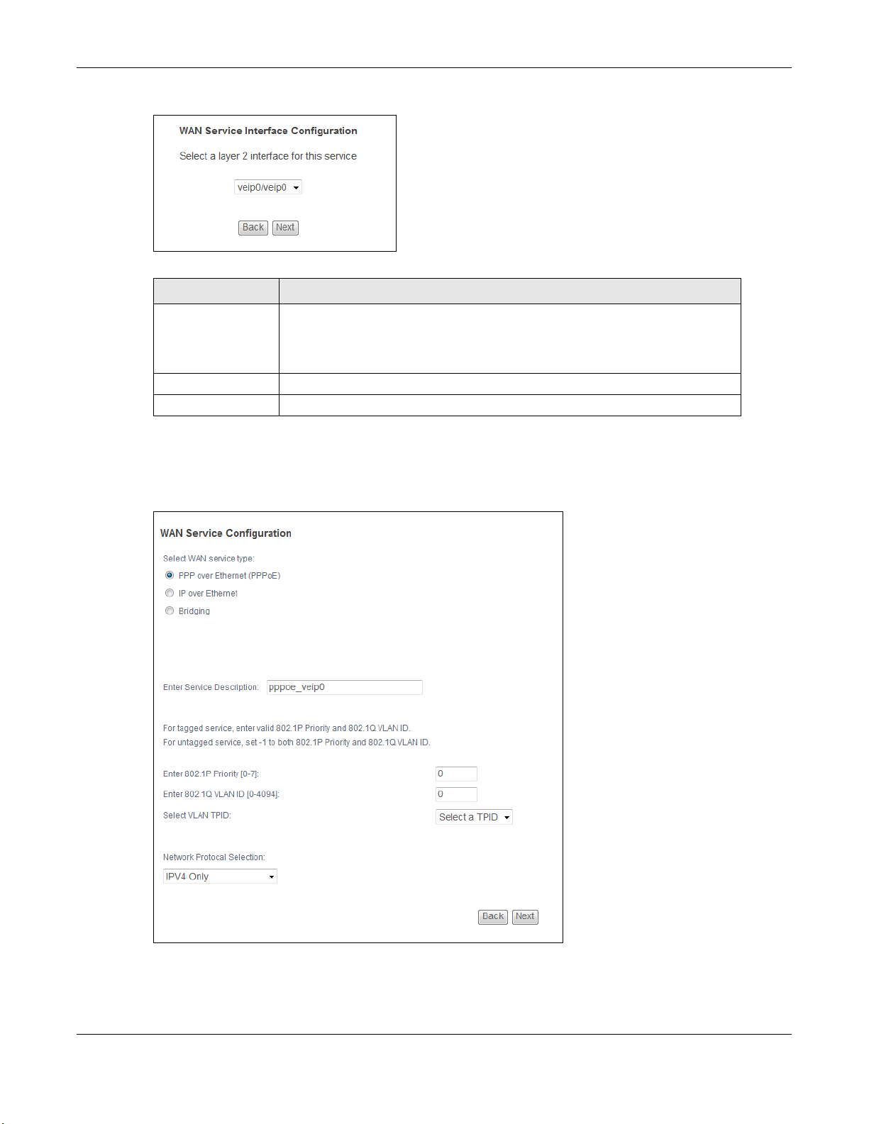
Figure 16 WAN Service: Interface Configuration
Table 12 WAN Service: Interface Configuration
LABEL DESCRIPTION
Select a layer 2
interface for this
service
Back Click this button to return to the previous screen.
Next Click this button to continue.
Select the port this WAN service uses for data transmission.
veip0/veip0 is the GPON port.
eth0 ~ eth3 represent the ethernet LAN ports 1 ~ 4.
4.2.1.2 WAN Service Configuration
Chapter 4 WAN
This screen displays after you select the WAN interface for a new WAN connection.
Figure 17 WAN Service: WAN Service Configuration
PMG5318-B20B User’s Guide
24

Chapter 4 WAN
Table 13 WAN Service: WAN Service Configuration
LABEL DESCRIPTION
Select WAN service
type
Allow as IGMP
Multicast Source
Allow as MLD
Multicast Source
Enter Service
Description
Enter 802.1P
Priority [0-7]
Enter 802.1Q VLAN
ID [0-4094]
Select VLAN TPID Select a Tag Protocol Identifier (TPID) the GPON Device to add it to the
Network Protocol
Selection
Back Click this button to return to the previous screen.
Next Click this button to continue.
Select the method of encapsulation used by your ISP.
Choices are PPP over Ethernet (PPPoE), IP over Ethernet and Bridging.
This displays when you select the Bridging service type. Select this to have
the GPON Device add routing table entries based on the IGMP traffic.
This displays when you select the Bridging service type. Select this to have
the GPON Device add routing table entries based on the MLD traffic.
Specify a name to identify the service.
veip0 stands for a virtual Ethernet card and is the foundation for veip0/*
which are virtual WAN interfaces of the physical GPON line.
eth0 ~ eth3 represent the ethernet LAN ports 1 ~ 4.
IEEE 802.1p defines up to 8 separate traffic types by inserting a tag into a
MAC-layer frame that contains bits to define class of service.
Type the IEEE 802.1p priority level (from 0 to 7) to add to traffic through this
connection. The greater the number, the higher the priority level.
You can configure this field after the OLT provisions a valid data path model
through OMCI (ONT Management Control Interface).
Type the VLAN ID number (from 0 to 4094) for traffic through this connection.
You can configure this field after the OLT provisions a valid data path model
through OMCI (ONT Management Control Interface).
service’s packets.
Select IPv4 Only to have the GPON Device use only IPv4.
Select IPv4&IPv6(Dual Stack) to let the GPON Device connect to IPv4 and
IPv6 networks an choose the protocol for applications according to the address
type. This lets the GPON Device use an IPv6 address when sending traffic
through this connection. You can only select this for a WAN service that uses
the PPPoE or IPoE encapsulation method over the layer 2 interface.
Select IPv6 Only to have the GPON Device use only IPv6.
4.2.1.3 WAN IP Address and DNS Server
The screen differs by the encapsulation you selected in the previous screen.
PPPoE
This screen displays when you select PPP over Ethernet (PPPoE) in the WAN Service
Configuration screen.
PMG5318-B20B User’s Guide
25
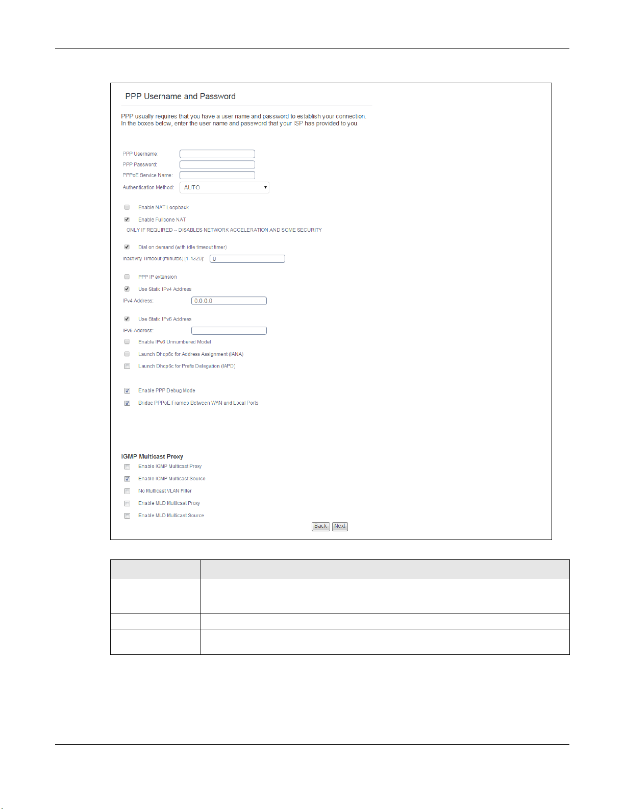
Figure 18 WAN Service: PPPoE
Chapter 4 WAN
Table 14 WAN Service: PPPoE
LABEL DESCRIPTION
PPP Username Enter the user name exactly as your ISP assigned. If assigned a name in the form
PPP Password Enter the password associated with the user name above.
PPPoE Service
Name
user@domain where domain identifies a service name, then enter both components
exactly as given.
Type the name of your PPPoE service here.
PMG5318-B20B User’s Guide
26

Chapter 4 WAN
Table 14 WAN Service: PPPoE (continued)
LABEL DESCRIPTION
Authentication
Method
Enable NAT
Loopback
Enable Fullcone NAT This field is available only when you select Enable NAT. Select this check box to
Dial on demand Select this to have the GPON Device only bring up the connection when there is traffic.
PPP IP extension Select this only if your service provider requires it. PPP IP extension extends the service
Use Static IPv4
Address
IPv4 Address Enter the IPv4 address assigned by your ISP.
Use Static IPv6
Address
IPv6 Address Enter the IPv6 address assigned by your ISP.
Enable IPv6
Unnumbered Model
Launch Dhcp6c for
Address
Assignment (IANA)
Launch Dhcp6c for
Prefix Delegation
(IAPD)
Enable PPP Debug
Mode
The GPON Device supports PAP (Password Authentication Protocol) and CHAP
(Challenge Handshake Authentication Protocol). CHAP is more secure than PAP;
however, PAP is readily available on more platforms.
Use the drop-down list box to select an authentication protocol for outgoing calls.
Options are:
AUTO - Your GPON Device accepts either CHAP or PAP when requested by this remote
node.
PAP - Your GPON Device accepts PAP only.
CHAP - Your GPON Device accepts CHAP only.
MSCHAP - Your GPON Device accepts MSCHAP only. MS-CHAP is the Microsoft version
of the CHAP.
Use this when you use NAT virtual server settings to forward traffic from the WAN to an
internal server with a private IP address on the LAN side. NAT loopback lets users on
the LAN connect to the external public WAN IP address of the GPON Device to access
the server on the LAN.
activate full cone NAT on this connection.
Specify after how many minutes of no traffic the GPON Device drops the connection.
provider’s IP subnet to a single LAN computer.
• It lets only one computer on the LAN connect to the WAN.
• The public IP address from the ISP is forwarded through DHCP to the LAN computer
instead of being used on the WAN PPP interface.
• It disables NAT and the firewall.
• DHCP tells the LAN computer to use the gateway as the default gateway and DNS
server.
• The GPON Device bridges IP packets between the WAN and LAN ports except
packets destined for the GPON Device’s LAN IP address.
Select this option if you have a fixed IPv4 address assigned by your ISP.
Select this option if you have a fixed IPv6 address assigned by your ISP.
Select this to enable IPv6 processing on the interface without assigning an explicit IPv6
address to the interface.
Select this check box to obtain an IPv6 address from a DHCPv6 server.
The IP address assigned by a DHCPv6 server has priority over the IP address
automatically generated by the GPON Device using the IPv6 prefix from an RA.
Select this to use DHCP PD (Prefix Delegation) that enables the Device to pass the IPv6
prefix information to its LAN hosts. The hosts can then use the prefix to generate their
IPv6 addresses.
Select this option to display PPP debugging messages on the console.
PMG5318-B20B User’s Guide
27

Chapter 4 WAN
Table 14 WAN Service: PPPoE (continued)
LABEL DESCRIPTION
Bridge PPPoE
Frames Between
WAN and Local
Ports
Enable IGMP
Multicast Proxy
Enable IGMP
Multicast Source
No Multicast VLAN
Filter
Enable MLD
Multicast Proxy
Enable MLD
Multicast Source
Back Click this button to return to the previous screen.
Next Click this button to continue.
This field displays when you do not have PPP IP extension selected. Select this option to
forward PPPoE packets from the WAN port to the LAN ports and from the LAN ports to
the WAN port.
In addition to the GPON Device's built-in PPPoE client, you can select this to allow up to
ten hosts on the LAN to use PPPoE client software on their computers to connect to the
ISP via the GPON Device. Each host can have a separate account and a public WAN IP
address.
This is an alternative to NAT for applications where NAT is not appropriate.
Clear this if you do not need to allow hosts on the LAN to use PPPoE client software on
their computers to connect to the ISP.
Select this check box to have the GPON Device act as an IGMP proxy on this connection.
This allows the GPON Device to get subscribing information and maintain a joined
member list for each multicast group. It can reduce multicast traffic significantly.
Select this check box to have the GPON Device add routing table entries based on the
IGMP traffic.
Select this check box to have the GPON Device not filter multicast traffic based on its
VLAN.
Select this check box to have the GPON Device act as an MLD proxy on this connection.
This allows the GPON Device to get subscription information and maintain a joined
member list for each multicast group. It can reduce multicast traffic significantly.
Select this check box to have the GPON Device add routing table entries based on the
MLD traffic.
IPoE
This screen displays when you select IP over Ethernet in the WAN Service Configuration
screen.
PMG5318-B20B User’s Guide
28
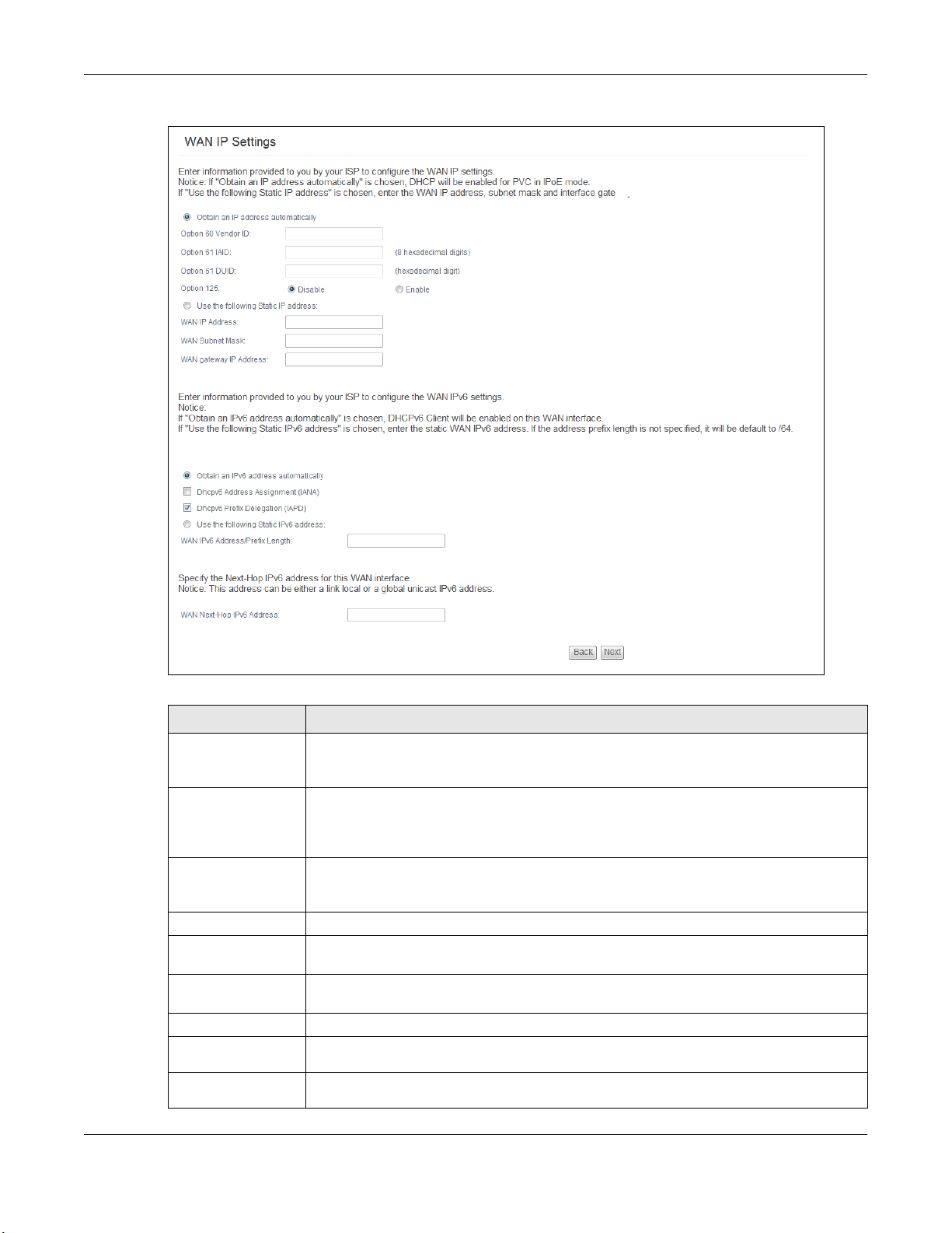
Figure 19 WAN Service: IPoE
Chapter 4 WAN
Table 15 WAN Service: IPoE
LABEL DESCRIPTION
Obtain an IP
address
automatically
Option 60 Vendor IDDHCP Option 60 identifies the vendor and functionality of the GPON Device in DHCP
Option 61 IAID DHCP Option 61 identifies the GPON Device in DHCP requests the GPON Device sends to
Option 61 DUID Enter the DHCP Unique Identifier (DUID) of the GPON Device.
Option 125 Enable this to add vendor specific information to DHCP requests that the GPON Device
Use the following
Static IP address
WAN IP Address Enter the static IP address provided by your ISP.
WAN Subnet
Mask
WAN gateway IP
Address
A static IP address is a fixed IP that your ISP gives you. A dynamic IP address is not
fixed; the ISP assigns you a different one each time you connect to the Internet. Select
this if you have a dynamic IP address.
requests that the GPON Device sends to a DHCP server when getting a WAN IP address.
Enter the Vendor Class Identifier (Option 60), such as the type of the hardware or
firmware.
a DHCP server when getting a WAN IP address. Enter the Identity Association Identifier
(IAID) of the GPON Device. For example, the WAN connection index number.
sends to a DHCP server when getting a WAN IP address.
Select this if you have a static IP address.
Enter the subnet mask provided by your ISP.
Enter the gateway IP address provided by your ISP.
PMG5318-B20B User’s Guide
29

Chapter 4 WAN
Table 15 WAN Service: IPoE (continued)
LABEL DESCRIPTION
Obtain an IPv6
address
automatically
Dhcpv6 Address
Assignment
Dhcp6c Prefix
Delegation
(IAPD)
Use the following
Static IPv6 address
WAN IPv6
Address/Prefix
Length
WAN Next-Hop
IPv6 Address
WAN Interface
Identifier Type
WAN Interface
Identifier
Back Click this button to return to the previous screen.
Next Click this button to continue.
Select this option to have the GPON Device use the IPv6 prefix from the connected
router’s Router Advertisement (RA) to generate an IPv6 address.
Select this check box to obtain an IPv6 address from a DHCPv6 server.
The IP address assigned by a DHCPv6 server has priority over the IP address
automatically generated by the GPON Device using the IPv6 prefix from an RA.
Select this to use DHCP PD (Prefix Delegation) that enables the Device to pass the IPv6
prefix information to its LAN hosts. The hosts can then use the prefix to generate their
IPv6 addresses.
Select this option if you have a fixed IPv6 address assigned by your ISP.
Enter the static IPv6 address and bit number of the IPv6 subnet mask provided by your
ISP.
Enter the gateway IPv6 address provided by your ISP.
Select Random to have the Device randomly configure a WAN Identifier, which is
shown in the WAN Interface Identifier field.
Select EUI-64 to use the EUI-64 format to generate an interface ID from the MAC
address of the WAN interface.
Select Manual to manually enter a WAN Identifier as the interface ID to identify the
WAN interface. The WAN Identifier is appended to the IPv6 address prefix to create the
routable global IPv6 address.
If you selected Random, this field is automatically configured.
If you selected Manual, enter the WAN Identifier in this field. The WAN identifier should
be unique and 64 bits in hexadecimal form. Every 16 bit block should be separated by a
colon as in XXXX:XXXX:XXXX:XXXX where X is a hexadecimal character. Blocks of zeros
can be represented with double colons as in XXXX:XXXX::XXXX.
4.2.1.4 NAT and IGMP Multicast
This screen is available only when you select IP over Ethe rnet in the WAN Service
Configuration screen.
PMG5318-B20B User’s Guide
30
 Loading...