

Page 1
Default Login Details
User’s Guide
PMG1005-T20B
GPON Optical Network Unit with 1-port GE LAN
LAN IP Address http://192.168.1.1
User Name admin
Password 1234
Version 1.00 Edition 1, 09/2017
Copyright © 2017 Zyxel Communications Corporation
Page 2

IMPORTANT!
READ CAREFULLY BEFORE USE.
KEEP THIS GUIDE FOR FUTURE REFERENCE.
This is a User’s Guide for a system managing a series of products. Not all products support all features.
Menushots and graphics in this book may differ slightly from what you see due to differences in release
versions or your computer operating system. Every effort has been made to ensure that the information
in this manual is accurate.
Related Documentation
•Quick Start Guide
The Quick Start Guide shows how to connect the managed device.
•More Information
Go to support.zyxel.com to find other information on the GPON Device
.
PMG1005-T20B User’s Guide
2
Page 3

Document Conventions
Document Conventions
Warnings and Notes
These are how warnings and notes are shown in this guide.
Warnings tell you about things that could harm you or your device.
Note: Notes tell you other important information (for example, other things you may need to
configure or helpful tips) or recommendations.
Syntax Conventions
• The PMG1005-T20B may be referred to as the “GPON Device” in this guide.
• Product labels, screen names, field labels and field choices are all in bold font.
• A right angle bracket (>) within a screen name denotes a mouse click. For example, Interface Setup >
LAN means you first click Interface Setup in the navigation panel, then LAN to get to that screen.
Icons Used in Figures
Figures in this user guide may use the following generic icons. The GPON Device may not be an exact
representation of your device.
GPON Device / ONU
PMG1005-T20B User’s Guide
3
Page 4

Table of Contents
Table of Contents
Document Conventions ............................................ ............................................ ..............................3
Table of Contents.................................................................................................................................4
Chapter 1
Introduction ..........................................................................................................................................6
1.1 Overview ........................................................................................................................................... 6
1.2 Managing the GPON Device ......................................................................................................... 6
1.3 Good Habits for Managing the GPON Device ............................................................................. 6
1.4 Hardware ........................................................................................................................................... 7
1.4.1 Front Panel ............................................................................................................................... 7
1.4.2 LEDs (Lights) ............................................................................................................................. 7
1.4.3 Bottom Panel ........................................................................................................................... 8
1.5 The Reset Button ............................................................................................................................... 8
1.5.1 Using the Reset Button ............................................................................................................ 8
1.6 Wall Mounting ................................................................................................................................... 9
Chapter 2
The Web Configurator........................................................................................................................11
2.1 Overview ........................................................................................................................................ 11
2.1.1 Accessing the Web Configurator ....................................................................................... 11
2.2 Web Configurator Main Screen .................................................................................................... 12
2.2.1 Title Bar ................................................................................................................................... 13
2.2.2 Navigation Panel .................................................................................................................. 13
2.2.3 Main Window ......................................................................................................................... 14
Chapter 3
Status...................................................................................................................................................15
3.1 Overview ......................................................................................................................................... 15
3.2 Device Info Screen ......................................................................................................................... 15
3.3 Statistics Screen .............................................................................................................................. 16
Chapter 4
LAN......................................................................................................................................................19
4.1 Overview ........................................................................................................................................ 19
4.2 LAN Screen ...................................................................................................................................... 19
Chapter 5
Access Management........................................................................................................................21
5.1 Overview ......................................................................................................................................... 21
PMG1005-T20B User’s Guide
4
Page 5

Table of Contents
5.2 SLID Screen ...................................................................................................................................... 21
Chapter 6
Maintenance......................................................................................................................................22
6.1 Overview ......................................................................................................................................... 22
6.2 Administration Screen ................................................................................................................... 22
6.3 Firmware Screen ............................................................................................................................. 22
6.4 SysRestart Screen ........................................................................................................................... 24
Chapter 7
Troubleshooting..................................................................................................................................25
7.1 Overview ......................................................................................................................................... 25
7.2 Power, Hardware Connections, and LEDs ................................................................................... 25
7.3 GPON Device Access and Login ................................................................................................. 26
7.4 Internet Access ............................................................................................................................... 27
Appendix A Customer Support ....................................................................................................... 29
Appendix B Legal Information......................................................................................................... 35
Index...................................................................................................................................................39
PMG1005-T20B User’s Guide
5
Page 6
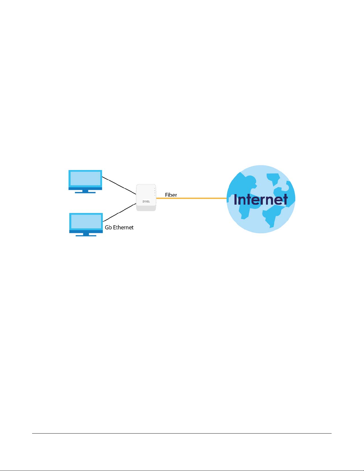
1.1 Overview
The PMG1005-T20B SFU (Single Family Unit) combines a fiber optic GPON (Gigabit Passive Optical
Network) ONT (Optical Network Terminal) with a built-in 1-port Gigabit Ethernet switch. Your GPON
Device provides shared Internet access through a fiber optic line connected to the PON port’s built-in
optical transceiver.
Figure 1 GPON Device Providing Internet Access
CHAPTER 1
Introduction
1.2 Managing the GPON Device
Use the GPON Device’s built-in Web Configurator to manage it. You can connect to it using a web
browser such as Firefox or Internet Explorer. The Web Configurator gives you access to all the available
settings for this product. For details on connecting to it, see the Section 2.1.1 on page 11.
1.3 Good Habits for Managing the GPON Device
Do the following things regularly to make the GPON Device more secure and to manage the GPON
Device more effectively.
• Change the web configurator login password. Use a password that’s not easy to guess and that
consists of different types of characters, such as numbers and letters.
• Write down the password and put it in a safe place.
• Back up the configuration (and make sure you know how to restore it). Restoring an earlier working
configuration may be useful if the GPON Device becomes unstable or even crashes. If you forget
your password, you will have to reset the GPON Device to its factory default settings. If you backed up
an earlier configuration file, you would not have to totally re-configure the GPON Device. You could
simply restore your last configuration.
PMG1005-T20B User’s Guide
6
Page 7
1.4 Hardware
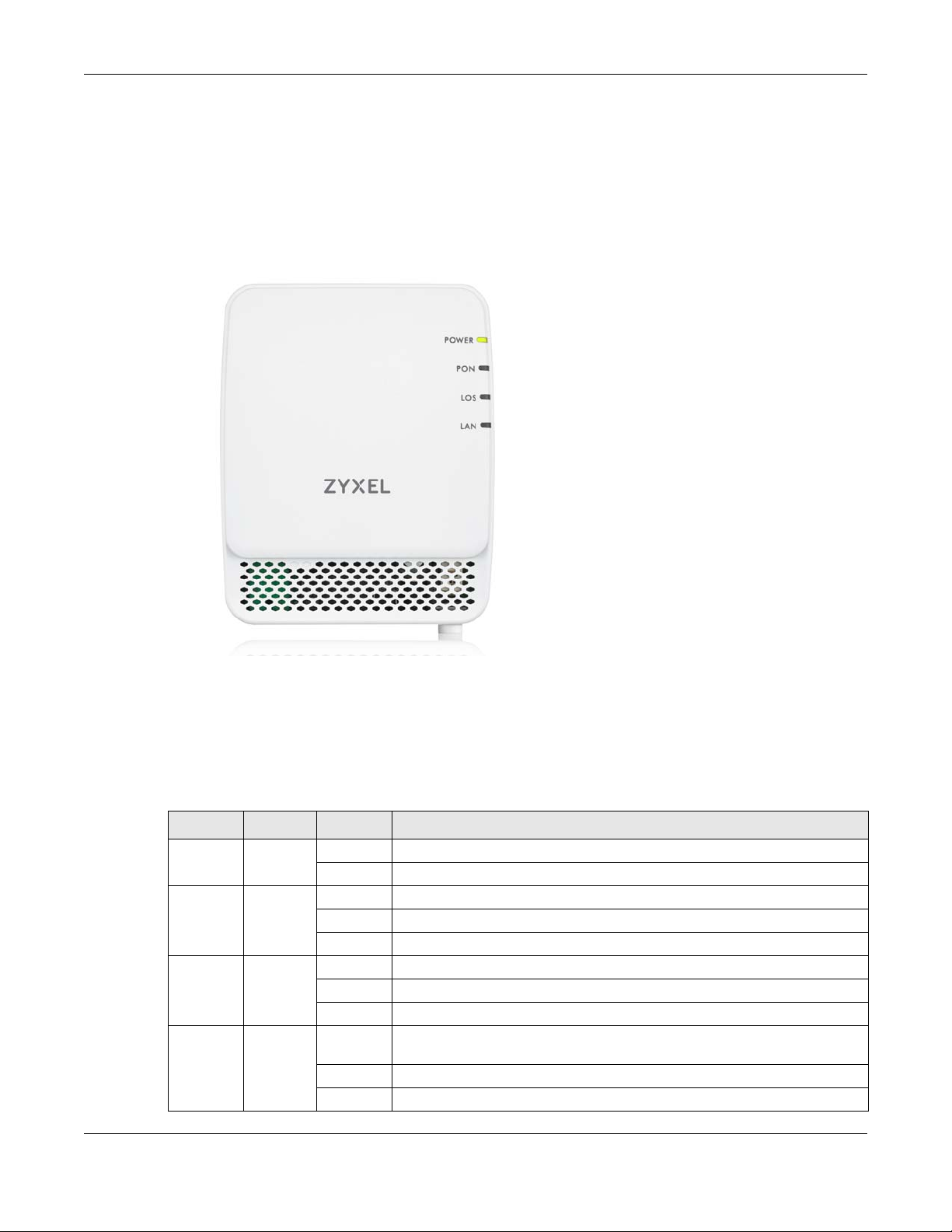
1.4.1 Front Panel
The following graphic displays the front panel of the GPON Device.
Figure 2 Front Panel
Chapter 1 Introduction
1.4.2 LEDs (Lights)
The following graphic displays the labels of the LEDs.
None of the LEDs are on if the GPON Device is not receiving power.
Table 1 LED Descriptions
LED COLOR STATUS DESCRIPTION
POWER Green On The GPON Device is receiving power and is ready for use.
PON Green On The GPON Device has successful fiber link.
LOS Red On The GPON Device is not receiving an optical signal.
LAN Green On The GPON Device has an Ethernet connection on the Local Area Network
Off The GPON Device is not receiving power.
Blinking The GPON Device’s PON port is syncing with OLT (fiber terminal).
Off The GPON Device’s PON port is not connected.
Blinking The GPON Device is receiving a weak optical signal.
Off The GPON Device is receiving a normal optical signal.
(LAN).
Blinking The GPON Device is transmitting/receiving data on the Ethernet .
Off The GPON Device does not have an Ethernet connection on the LAN.
PMG1005-T20B User’s Guide
7
Page 8
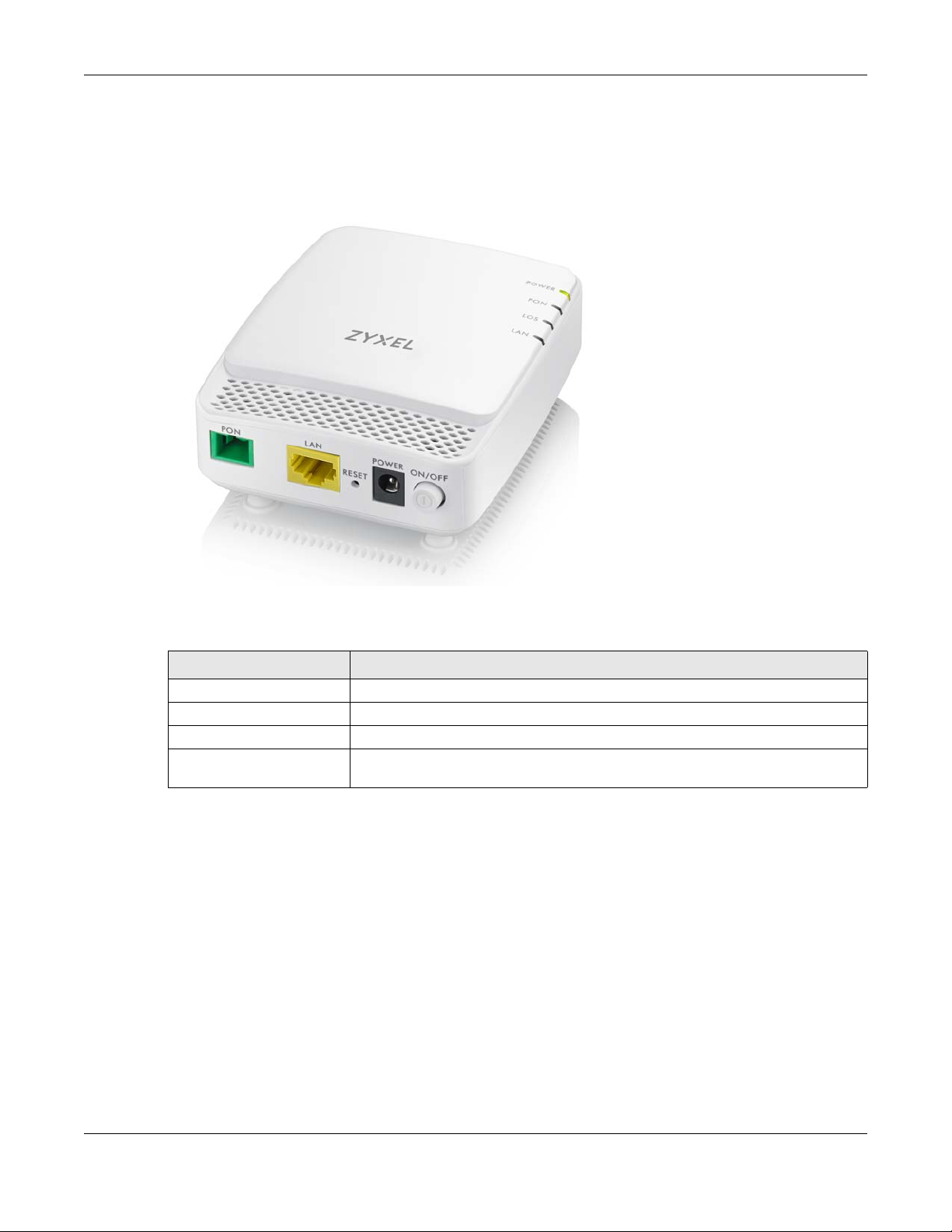
1.4.3 Bottom Panel
The following graphic displays the rear panel of the GPON Device.
Figure 3 Bottom Panel
Chapter 1 Introduction
The following table describes the items on the bottom panel.
Table 2 Rear Panel Ports
LABEL DESCRIPTION
PON Connect a fiber optic cable to the PON port for Internet Access.
LAN Connect a computer or another Ethernet device to the LAN port for Internet access.
RESET Press the button to return the GPON Device to the factory defaults.
POWER Connect the power cable (12V 0.5A) can press the ON/OFF button to start the
device.
1.5 The Reset Button
If you forget your password or cannot access the Web Configurator, you will need to use the RESET
button at the back of the GPON Device to reload the factory-default configuration file. This means that
you will lose all custom configuration and the password will be reset to the default.
1.5.1 Using the Reset Button
1 Make sure the POWER LED is on (not blinking).
2 To set the GPON Device back to the factory default settings (LAN IP address 192.168.1.1, user name
admin and password 1234), press the RESET button for more than three seconds and then release it. The
LEDs flash and the GPON Device restores the defaults and restarts.
PMG1005-T20B User’s Guide
8
Page 9

Note: Press the RESET button for less than one second to restart the GPON Device without
changing it back to the factory default settings.
1.6 Wall Mounting
You may need screw anchors if mounting on a concrete or brick wall.
Note: The screws and screw anchors are not included.
Table 3 Wall Mounting Information
Distance between holes 54 mm
M4.2 Screws Two
Screw anchors (optional) Two
1 Select a position free of obstructions on a wall strong enough to hold the weight of the device.
2 Mark two holes on the wall at the appropriate distance apart for the screws.
Chapter 1 Introduction
Be careful to avoid damaging pipes or cables located inside the wall
when drilling holes for the screws.
3 If using screw anchors, drill two holes for the screw anchors into the wall. Push the anchors into the full
depth of the holes, then insert the screws into the anchors. Do not insert the screws all the way in - leave
a small gap of about 0.5 cm.
If not using screw anchors, use a screwdriver to insert the screws into the wall. Do not insert the screws all
the way in - leave a gap of about 0.5 cm
4 Make sure the screws are fastened well enough to hold the weight of the GPON Device with the
connection cables.
5 Align the holes on the back of the GPON Device with the screws on the wall. Hang the GPON Device on
the screws.
PMG1005-T20B User’s Guide
9
Page 10
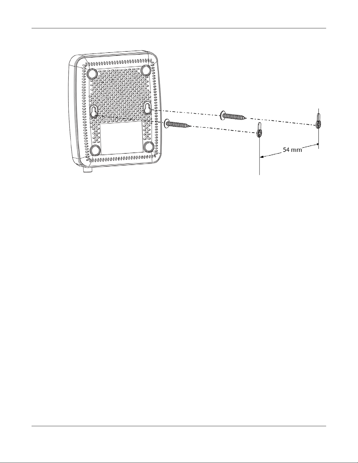
Figure 4 Wall Mounting Example
Chapter 1 Introduction
PMG1005-T20B User’s Guide
10
Page 11

2.1 Overview
The Web Configurator is an HTML-based management interface that allows easy GPON Device setup
and management via Internet browser. You can use the following browsers:
• Internet Explorer 11.0 and later and later versions.
• Google Chrome 60.0.3112.113 and later versions.
• Mozilla Firefox 55.0.3 and later versions.
In order to use the Web Configurator you need to allow:
• Web browser pop-up windows from your GPON Device. Web pop-up blocking is enabled by default
in Windows XP SP (Service Pack) 2.
• JavaScript (enabled by default).
• Java permissions (enabled by default).
CHAPTER 2
The Web Configurator
2.1.1 Accessing the Web Configurator
1 Make sure your GPON Device hardware is properly connected (see the Quick Start Guide for details).
2 Make sure your computer’s IP address is in the same subnet as the GPON Device. Check your
computer’s help to see how to change your IP address.
3 Launch your web browser.
4 Type the default GPON Device address shown on the cover page of this User’s Guide as the URL.
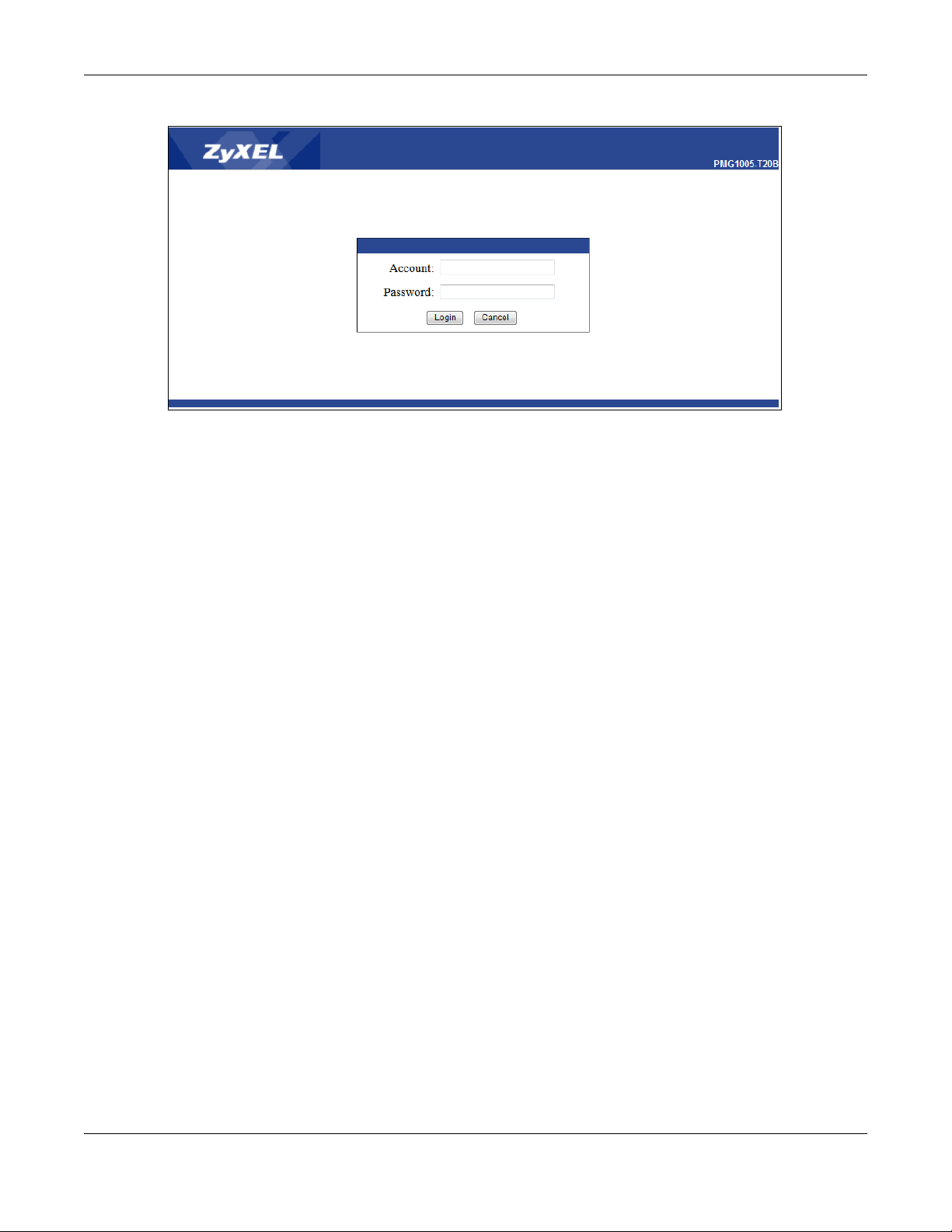
5 A login screen displays. Enter the user name and password shown on the cover page of this User’s Guide
and click Login.
PMG1005-T20B User’s Guide
11
Page 12
Chapter 2 The Web Configurator
Figure 5 Login Screen
Note: For security reasons, the GPON Device automatically logs you out if you do not use the
Web Configurator for an extended period of time. If this happens, log in again.
2.2 Web Configurator Main Screen
The main screen is divided into these parts:
PMG1005-T20B User’s Guide
12
Page 13

Figure 6 Main Screen
B
C
A
Chapter 2 The Web Configurator
• A - title bar
• B - navigation panel
• C - main window
2.2.1 Title Bar
Click Logout to log out of the Web Configurator.
2.2.2 Navigation Panel
The following table describes the menu items on the navigation panel.
Table 4 Navigation Panel Summary
LINK TAB FUNCTION
Interface
Setup
Access
Management
Maintenance Administration Use this screen to change your GPON Device’s password.
LAN Use this screen to configure your GPON Device’s LAN IP address and subnet
Auth Use this screen to change your GPON Device’s Subscriber Location ID (SLID)
Firmware Use this screen to upload firmware to your GPON Device.
SysRestart Use this screen to keep your GPON Device’s configuration (settings) after reboot
mask.
setting. The SLID identifies your device to the GPON service provider.
or reset the factory default settings.
PMG1005-T20B User’s Guide
13
Page 14

Table 4 Navigation Panel Summary
LINK TAB FUNCTION
Status Device Info This screen shows the GPON Device’s general device and network status
2.2.3 Main Window
The main window displays information and configuration fields. It is discussed in the rest of this
document. The Device Info screen displays after you log in. See Chapter 3 on page 15 for details about
the Device Info screen.
Chapter 2 The Web Configurator
information.
Statistics Use this screen to view the GPON Device’s traffic statistics through the Ethernet
or the PON interface.
PMG1005-T20B User’s Guide
14
Page 15

3.1 Overview
• Use the Device Info screen to see the GPON Device’s general device and network status information
(Section 3.2 on page 15).
• Use the Statistics screen to view the GPON Device’s traffic statistics through the Ethernet or the PON
interface(Section 3.3 on page 16).
3.2 Device Info Screen
Click Status > Device Info to see the current status of the GPON Device, its system resources, and
interfaces.
CHAPTER 3
Status
Figure 7 Status > Device Info
PMG1005-T20B User’s Guide
15
Page 16

Chapter 3 Status
Each field is described in the following table.
Table 5 Status > Device Info
LABEL DESCRIPTION
Device Information
Firmware Version This field displays the current version of the firmware the GPON Device uses.
Hardware version This field displays the current version of the hardware of the GPON Device.
MAC Address This is the MAC (Media Access Control) address unique to your GPON Device. The MAC
Model Name
Model Name This field displays the model name of the GPON Device.
LAN
IPv4
IP Address This field displays the current IP address of the GPON Device in the LAN. Click this to go to
Subnet Mask This field displays the GPON Device’s LAN subnet mask.
GPON
Link State This field displays Up when the interface has a connection with OLT (fiber terminal) and
Transceiver
Rx Power This field displays the transceiver’s optical receiving power in dBm. The normal range is -6 to
Tx Power This field displays the transceiver’s optical transmitting power in dBm. The normal range is .5
Tx Bias Current This field displays the transceiver’s bias current in mA. The normal range is 4-50 mA.
Supply Voltage This field displays the transceiver’s voltage in Volts. The normal range is 3.13-3.47 Volts.
Temperature This field displays the transceiver’s temperature in Celsius. The normal range is 0-70 degrees.
address uses six pairs of hexadecimal notation and follows an industry standard that
ensures no other adapter has the same address.
the screen where you can change it.
Down when it does not.
-28 dBm.
to 5 dBm.
3.3 Statistics Screen
Use this screen to look at the current number of the GPON Device packets received through the
Ethernet or the PON interface. Click Status > Statistics to open the following screen.
PMG1005-T20B User’s Guide
16
Page 17

Chapter 3 Status
Figure 8 Status > Statistics: Ethernet Interface
Figure 9 Status > Statistics: PON Interface
Each field is described in the following table.
Table 6 Status > Statistics
LABEL DESCRIPTION
Interface Select Ethernet or PON to show the GPON Device’s traffic statistics.
The following fields show detailed information about the Ethernet packets transmitted and received.
Transmit Statistics
Transmit Frames This field shows the number of transmitted frames on this port
Transmit Multicast
Frames
Transmit total
Bytes
Transmit Collision This field shows information on collisions while transmitting.
Transmit Error
Frames
Receive Statistics
Receive Frames This field shows the number of received frames on this port.
Receive Multicast
Frames
Receive total
Bytes
This field shows the number of good multicast frames transmitted.
This field shows the number of total bytes transmitted on this port.
This field shows the number of transmitted errors frames on this port.
This field shows the number of good multicast frames received.
This field shows the number of total bytes received on this port.
PMG1005-T20B User’s Guide
17
Page 18

Chapter 3 Status
Table 6 Status > Statistics
LABEL DESCRIPTION
Receive CRC
Errors
Receive Undersize Frames
The following fields show detailed information about the PON packets transmitted and received.
Transmit Statistics
Tx Packets Count This field shows a count of successfully transmitted packets on this port.
Tx Bytes Count This field shows a count of successfully transmitted bytes on this port.
Transmit Multicast
Frames
Transmit
Broadcast Frames
Transmit Collision This field shows information on collisions while transmitting.
Transmit Undersize Frames
Receive Statistics
Rx Packets Count This field shows a count of successfully received packets on this port.
Rx Bytes Count This field shows a count of successfully received bytes on this port.
Receive Multicast
Frames
Receive
Broadcast Frames
Receive CRC
Errors
Receive Undersize Frames
REFRESH Click Refresh to renew the screen.
This field shows the number of packets received with CRC (Cyclic Redundant Check)
error(s).
This field shows the number of frames received that were shorter than 64 octets in length.
This field shows the number of good multicast frames transmitted.
This field shows the number of good broadcast frames transmitted.
This field shows the number of frames transmitted that were shorter than 64 octets in length.
This field shows the number of good multicast frames received.
This field shows the number of good broadcast frames received.
This field shows the number of packets received with CRC (Cyclic Redundant Check)
error(s).
This field shows the number of frames received that were shorter than 64 octets in length.
PMG1005-T20B User’s Guide
18
Page 19

4.1 Overview
This chapter describes how to configure LAN settings.
A Local Area Network (LAN) is a shared communication system to which many computers are
attached. A LAN is a computer network limited to the immediate area, usually the same building or floor
of a building.
4.2 LAN Screen
Click Interface Setup > LAN to open the LAN screen. Use this screen to set the Local Area Network IP
address and subnet mask of your GPON Device.
CHAPTER 4
LAN
Figure 10 Interface Setup > LAN
The following table describes the fields in this screen.
Table 7 Interface Setup > LAN
LABEL DESCRIPTION
Router Local IP
IP Address Enter the LAN IP address you want to assign to your GPON Device in dotted decimal
notation, for example, 192.168.1.1 (factory default).
IP Subnet Mask Type the subnet mask of your network in dotted decimal notation, for example
Alias IP Address Enter the IP address of your GPON Device in dotted decimal notation.
255.255.255.0 (factory default). Your GPON Device automatically computes the subnet
mask based on the IP address you enter, so do not change this field unless you are
instructed to do so.
PMG1005-T20B User’s Guide
19
Page 20

Chapter 4 LAN
Table 7 Interface Setup > LAN
LABEL DESCRIPTION
Alias IP Subnet Mask Your GPON Device will automatically calculate the subnet mask based on the IP address
that you assign. Unless you are implementing subnetting, use the subnet mask computed
by the GPON Device.
Snoop Select Activated to enable IGMP Snooping to forward group multicast traffic only to ports
Dynamic Route RIP (Routing Information Protocol) allows a router to exchange routing information with
Direction Use this field to control how much routing information the GPON Device sends and
SAVE Click SAVE to save your changes back to the GPON Device.
CANCEL Click CANCEL to begin configuring this screen afresh.
that are members of that group. Otherwise, select Deactivated.
other routers.
Select the RIP version from RIP1 or RIP2.
receives on the subnet.
Select the RIP direction from None, Both, IN Only and OUT Only.
PMG1005-T20B User’s Guide
20
Page 21

5.1 Overview
• Use the SLID screen to change your GPON Device’s Subscriber Location ID (SLID) setting (Section 5.2
on page 21).
5.2 SLID Screen
To change your GPON Device’s Subscriber Location ID (SLID) setting, click Access Management > Auth.
The screen appears as shown. The SLID identifies your device to the GPON service provider’s
Line Terminal (OLT). If your GPON service provider gave you an SLID to use, enter it in this screen.
Figure 11 Access Management > Auth
CHAPTER 5
Access Management
Optical
The following table describes the fields in this screen.
Table 8 Access Management > Auth
LABEL DESCRIPTION
SLID Enter the SLID used for gaining access to the service provider’s network. It is case-sensitive,
so make sure [Caps Lock] is not on.
APPLY Click APPLY to save your changes back to the GPON Device.
PMG1005-T20B User’s Guide
21
Page 22

6.1 Overview
• Use the Administration screen to change your GPON Device’s password (Section 6.2 on page 22).
• Use the Firmware screen to upload firmware to your GPON Device (Section 6.3 on page 22).
• Use the SysRestart screen to backup/restore or reboot the GPON Device without turning the power off
(Section 6.4 on page 24).
6.2 Administration Screen
Use this screen to configure the GPON Device’s password. Click Maintenance > Administration to open
the Administration screen.
CHAPTER 6
Maintenance
Figure 12 Maintenance > Administration
The following table describes the labels in this screen.
Table 9 Maintenance > Administration
LABEL DESCRIPTION
New Password Type your new system password (up to 30 characters). Note that as you type a password, the
Confirm Password
SAVE Click SAVE to save your changes back to the GPON Device.
CANCEL Click CANCEL to begin configuring this screen afresh.
screen displays a (*) for each character you type. After you change the password, use the
new password to access the GPON Device.
Type the new password again for confirmation.
6.3 Firmware Screen
Use the instructions in this screen to back up (save) the GPON Device’s configuration file or upgrade its
firmware. After you configure your GPON Device, you can backup the configuration file to a computer.
PMG1005-T20B User’s Guide
22
Page 23

Chapter 6 Maintenance
That way if you later misconfigure the GPON Device, you can upload the backed up configuration file
to return to your previous settings. You can alternately upload the factory default configuration file if you
want to return the GPON Device to the original default settings. The firmware determines the GPON
Device’s available features and functionality.
Follow the instructions in this screen to upload firmware to your GPON Device. The upload process uses
HTTP (Hypertext Transfer Protocol) and may take up to two minutes. After a successful upload, the
system will reboot automatically.
Click Maintenance > Firmware to open the following screen.
Figure 13 Maintenance > Firmware
The following table describes the labels in this screen.
Table 10 Maintenance > Firmware
LABEL DESCRIPTION
Firmware
Upgrade
New Firmware
Location
Browse... Click Browse... to find the .bin or .rom configuration file you want to upload. Remember that
ROMFILE BACKUP Click ROMFILE BACKUP to save the GPON Device’s current configuration to your computer.
UPGRADE Click UPGRADE to begin the upload a new firmware (FW) or configuration file (romfile). This
Select the romfile radio button to restore a backed-up configuration file to return to the GPON
Device.
Select the FW radio button to load a previously downloaded firmware to the GPON Device.
Type in the location of the file you want to upload in this field or click Browse... to find it.
you must decompress compressed (.zip) files before you can upload them.
process may take up to two minutes.
Do NOT turn off the GPON Device while a firmware upload is in progress!
After you see File upload succeeded, starting flash erasing and programming!! in the screen, wait three
minutes before logging into the GPON Device again.
The GPON Device automatically restarts in this time causing a temporary network disconnect.
After two minutes, log in again and check your new firmware version in the Device Info screen.
If the upload was not successful, an error message appears.
PMG1005-T20B User’s Guide
23
Page 24

6.4 SysRestart Screen
System restart allows you to reboot the GPON Device using the current settings or factory default
settings without turning the power off. Click Maintenance > SysRestart. Click RESTART to have the GPON
Device reboot. This does not affect the GPON Device's configuration.
Figure 14 Maintenance > SysRestart
The following table describes the labels in this screen.
Table 11 Maintenance > SysRestart
LABEL DESCRIPTION
System Restart
with
Select Current Settings to keep your configuration settings after the GPON Device reboots. This
does not affect the GPON Device’s configuration.
Chapter 6 Maintenance
Select Factory Default Settings to clear all user-defined configuration information and return
the GPON Device to its factory defaults (LAN IP address 192.168.1.1, user name admin and
password 1234). To log in again you may have to change your computer’s IP address, so that
it’s in the same subnet as the GPON Device.
RESTART Click this to reboot the GPON Device.
PMG1005-T20B User’s Guide
24
Page 25

CHAPTER 7
Troubleshooting
7.1 Overview
This chapter offers some suggestions to solve problems you might encounter. The potential problems are
divided into the following categories.
• Power, Hardware Connections, and LEDs
• GPON Device Access and Login
• Internet Access
7.2 Power, Hardware Connections, and LEDs
The GPON Device does not turn on. None of the LEDs turn on.
1 Make sure the GPON Device is turned on.
2 Make sure you are using the power adapter or cord included with the GPON Device.
3 Make sure the power adapter or cord is connected to the GPON Device and plugged in to an
appropriate power source. Make sure the power source is turned on.
4 Turn the GPON Device off and on.
5 If the problem continues, contact the vendor.
One of the LEDs does not behave as expected.
1 Make sure you understand the normal behavior of the LED. The PON LED turns off if the optical
transceiver has malfunctioned or the fiber cable is not connected or is broken or damaged enough to
break the PON connection. See Section 1.4 on page 7 for details about the other LEDs.
2 Check the hardware connections. See the Quick Start Guide for details.
3 Inspect your cables for damage. Contact the vendor to replace any damaged cables.
4 Turn the GPON Device off and on.
PMG1005-T20B User’s Guide
25
Page 26

Chapter 7 Troubleshooting
5 If the problem continues, contact the vendor.
7.3 GPON Device Access and Login
I forgot the IP address for the GPON Device.
1 The default IP address is 192.168.1.1.
2 If you changed the IP address and have forgotten it, reset the GPON Device to its factory defaults. See
Section 1.5 on page 8.
I cannot see or access the Login screen in the Web Configurator.
1 Make sure you are using the correct IP address.
• The default IP address is 192.168.1.1.
• If you changed the IP address, use the new IP address.
• If you changed the IP address and have forgotten it, reset the GPON Device to its factory defaults.
See Section 1.5 on page 8.
2 Check the hardware connections, and make sure the LEDs are behaving as expected. See Section 1.4
on page 7.
3 Make sure your computer’s IP address is in the same subnet as the GPON Device.
4 Make sure your Internet browser does not block pop-up windows and has Javascript and Java enabled.
5 Reset the GPON Device to its factory defaults, and try to access the GPON Device with the default IP
address. See Section 1.5 on page 8.
6 If the problem continues, contact the network administrator or vendor.
I can see the Login screen, but I cannot log in to the GPON Device.
1 Make sure you have entered the user name and password correctly. The default user name is shown on
the cover page of this User’s Guide. These fields are case-sensitive, so make sure [Caps Lock] is not on.
2 You cannot log in to the Web Configurator while someone is using Telnet to access the GPON Device.
Log out of the GPON Device in the other session, or ask the person who is logged in to log out.
3 Turn the GPON Device off for ten seconds and then back on.
PMG1005-T20B User’s Guide
26
Page 27

4 If this does not work, you have to reset the GPON Device to its factory defaults. See Section 1.5 on page
8.
7.4 Internet Access
I cannot access the Internet.
1 Check the hardware connections, and make sure the LEDs are behaving as expected.
The PON LED turns off if the optical transceiver has malfunctioned or the fiber cable is not connected or
is broken or damaged enough to break the PON connection.
The LOS LED turns red if the GPON Device is not receiving an optical signal.
The LOS LED turns blinking red if the GPON Device is receiving a weak optical signal.
See Section 1.4 on page 7 for details about the other LEDs.
Chapter 7 Troubleshooting
2 Make sure you entered the ISP account information correctly in your computer. These fields are case-
sensitive, so make sure [Caps Lock] is not on.
3 Disconnect all the cables from your GPON Device (refer to the Quick Start Guide).
4 Turn the GPON Device off and on.
5 If the problem continues, contact the ISP.
I cannot access the Internet anymore. I had access to the Internet (with the GPON Device), but
my Internet connection is not available anymore.
1 Check the hardware connections, and make sure the LEDs are behaving as expected. The PON LED
turns off if the optical transceiver has malfunctioned or the fiber cable is not connected or is broken or
damaged enough to break the PON connection. See Section 1.4 on page 7 for details about the other
LEDs.
2 Turn the GPON Device off and on.
3 If the problem appears to be the GPON Device, contact your vendor.
The Internet connection is slow or intermittent.
1 Make sure the LEDs are behaving as expected.
The LOS LED turns blinking red if the GPON Device is receiving a weak optical signal.
PMG1005-T20B User’s Guide
27
Page 28

Chapter 7 Troubleshooting
2 There might be a lot of traffic on the network. Look at the LEDs (see Section 1.4 on page 7). If the GPON
Device is sending or receiving a lot of information, try closing some programs that use the Internet,
especially peer-to-peer applications.
3 Turn the GPON Device off and on.
4 If the problem continues, contact the network administrator or vendor.
PMG1005-T20B User’s Guide
28
Page 29

APPENDIX A
Customer Support
In the event of problems that cannot be solved by using this manual, you should contact your vendor. If
you cannot contact your vendor, then contact a Zyxel office for the region in which you bought the
device.
See http://www.zyxel.com/homepage.shtml and also
http://www.zyxel.com/about_zyxel/zyxel_worldwide.shtml for the latest information.
Please have the following information ready when you contact an office.
Required Information
• Product model and serial number.
• Warranty Information.
• Date that you received your device.
• Brief description of the problem and the steps you took to solve it.
Corporate Headquarters (Worldwide)
Taiwan
• Zyxel Communications Corporation
• http://www.zyxel.com
Asia
China
• Zyxel Communications (Shanghai) Corp.
Zyxel Communications (Beijing) Corp.
Zyxel Communications (Tianjin) Corp.
• http://www.zyxel.cn
India
•Zyxel Technology India Pvt Ltd
• http://www.zyxel.in
Kazakhstan
•Zyxel Kazakhstan
• http://www.zyxel.kz
NCC User’s Guide
29
Page 30

Korea
• Zyxel Korea Corp.
• http://www.zyxel.kr
Malaysia
• Zyxel Malaysia Sdn Bhd.
• http://www.zyxel.com.my
Pakistan
• Zyxel Pakistan (Pvt.) Ltd.
• http://www.zyxel.com.pk
Philippines
• Zyxel Philippines
• http://www.zyxel.com.ph
Singapore
• Zyxel Singapore Pte Ltd.
• http://www.zyxel.com.sg
Appendix A Customer Support
Europe
Taiwan
• Zyxel Communications Corporation
• http://www.zyxel.com/tw/zh/
Thailand
• Zyxel Thailand Co., Ltd
• http://www.zyxel.co.th
Vietnam
• Zyxel Communications Corporation-Vietnam Office
• http://www.zyxel.com/vn/vi
Austria
•Zyxel Deutschland GmbH
• http://www.zyxel.de
Belarus
•Zyxel BY
• http://www.zyxel.by
NCC User’s Guide
30
Page 31

Appendix A Customer Support
Belgium
• Zyxel Communications B.V.
• http://www.zyxel.com/be/nl/
• http://www.zyxel.com/be/fr/
Bulgaria
•Zyxel България
• http://www.zyxel.com/bg/bg/
Czech Republic
• Zyxel Communications Czech s.r.o
• http://www.zyxel.cz
Denmark
• Zyxel Communications A/S
• http://www.zyxel.dk
Estonia
• Zyxel Estonia
• http://www.zyxel.com/ee/et/
Finland
• Zyxel Communications
• http://www.zyxel.fi
France
•Zyxel France
• http://www.zyxel.fr
Germany
•Zyxel Deutschland GmbH
• http://www.zyxel.de
Hungary
• Zyxel Hungary & SEE
• http://www.zyxel.hu
Italy
• Zyxel Communications Italy
• http://www.zyxel.it/
NCC User’s Guide
31
Page 32

Appendix A Customer Support
Latvia
•Zyxel Latvia
• http://www.zyxel.com/lv/lv/homepage.shtml
Lithuania
•Zyxel Lithuania
• http://www.zyxel.com/lt/lt/homepage.shtml
Netherlands
• Zyxel Benelux
• http://www.zyxel.nl
Norway
• Zyxel Communications
• http://www.zyxel.no
Poland
• Zyxel Communications Poland
• http://www.zyxel.pl
Romania
• Zyxel Romania
• http://www.zyxel.com/ro/ro
Russia
• Zyxel Russia
• http://www.zyxel.ru
Slovakia
• Zyxel Communications Czech s.r.o. organizacna zlozka
• http://www.zyxel.sk
Spain
• Zyxel Communications ES Ltd
• http://www.zyxel.es
Sweden
• Zyxel Communications
• http://www.zyxel.se
Switzerland
•Studerus AG
NCC User’s Guide
32
Page 33

• http://www.zyxel.ch/
Turkey
• Zyxel Turkey A.S.
• http://www.zyxel.com.tr
UK
• Zyxel Communications UK Ltd.
• http://www.zyxel.co.uk
Ukraine
•Zyxel Ukraine
• http://www.ua.zyxel.com
Latin America
Argentina
• Zyxel Communication Corporation
• http://www.zyxel.com/ec/es/
Appendix A Customer Support
Brazil
• Zyxel Communications Brasil Ltda.
• https://www.zyxel.com/br/pt/
Ecuador
• Zyxel Communication Corporation
• http://www.zyxel.com/ec/es/
Middle East
Israel
• Zyxel Communication Corporation
• http://il.zyxel.com/homepage.shtml
Middle East
• Zyxel Communication Corporation
• http://www.zyxel.com/me/en/
NCC User’s Guide
33
Page 34

North America
USA
• Zyxel Communications, Inc. - North America Headquarters
• http://www.zyxel.com/us/en/
Oceania
Australia
• Zyxel Communications Corporation
• http://www.zyxel.com/au/en/
Africa
South Africa
• Nology (Pty) Ltd.
• http://www.zyxel.co.za
Appendix A Customer Support
NCC User’s Guide
34
Page 35

Copyright
Copyright © 2017 by Zyxel Communications Corporation.
The contents of this publication may not be reproduced in any part or as a whole, transcribed, stored in a retrieval system, translated into any
language, or transmitted in any form or by any means, electronic, mechanical, magnetic, optical, chemical, photocopying, manual, or
otherwise, without the prior written permission of Zyxel Communications Corporation.
Published by Zyxel Communications Corporation. All rights reserved.
Disclaimer
Zyxel does not assume any liability arising out of the application or use of any products, or software described herein. Neither does it convey any
license under its patent rights nor the patent rights of others. Zyxel further reserves the right to make changes in any products described herein
without notice. This publication is subject to change without notice.
Regulatory Notice and Statement
UNITED STATES of AMERICA
APPENDIX B
Legal Information
The following information applies if you use the product within USA area.
FCC EMC Statement
• The device complies with Part 15 of FCC rules. Operation is subject to the following two conditions:
(1) This device may not cause harmful interference, and
(2) This device must accept any interference received, including interference that may cause undesired operation.
• Changes or modifications not expressly approved by the party responsible for compliance could void the user’s authority to operate the
device.
• This product has been tested and complies with the specifications for a Class B digital device, pursuant to Part 15 of the FCC Rules. These
limits are designed to provide reasonable protection against harmful interference in a residential installation. This device generates, uses, and
can radiate radio frequency energy and, if not installed and used according to the instructions, may cause harmful interference to radio
communications. However, there is no guarantee that interference will not occur in a particular installation.
• If this device does cause harmful interference to radio or television reception, which is found by turning the device off and on, the user is
encouraged to try to correct the interference by one or more of the following measures:
• Reorient or relocate the receiving antenna
• Increase the separation between the devices
• Connect the equipment to an outlet other than the receiver’s
• Consult a dealer or an experienced radio/TV technician for assistance
CANADA
The following information applies if you use the product within Canada area
Industry Canada ICES statement
CAN ICES-3 (B)/NMB-3(B)
EUROPEAN UNION
The following information applies if you use the product within the European Union.
PMG1005-T20B User’s Guide
35
Page 36

Appendix B Legal Information
List of national codes
COUNTRY ISO 3166 2 LETTER CODE COUNTRY ISO 3166 2 LETTER CODE
Austria AT Liechtenstein LI
Belgium BE Lithuania LT
Bulgaria BG Luxembourg LU
Croatia HR Malta MT
Cyprus CY Netherlands NL
Czech Republic CZ Norway NO
Denmark DK Poland PL
Estonia EE Portugal PT
Finland FI Romania RO
France FR Serbia RS
Germany DE Slovakia SK
Greece GR Slovenia SI
Hungary HU Spain ES
Iceland IS Switzerland CH
Ireland IE Sweden SE
Italy IT Turkey TR
Latvia LV United Kingdom GB
Safety Warnings
• Do not use this product near water, for example, in a wet basement or near a swimming pool.
• Do not expose your device to dampness, dust or corrosive liquids.
• Do not store things on the device.
• Do not obstruct the device ventilation slots as insufficient airflow may harm your device. For example, do not place the device in an
enclosed space such as a box or on a very soft surface such as a bed or sofa.
• Do not install, use, or service this device during a thunderstorm. There is a remote risk of electric shock from lightning.
• Connect ONLY suitable accessories to the device.
• Do not open the device or unit. Opening or removing covers can expose you to dangerous high voltage points or other risks.
• Only qualified service personnel should service or disassemble this device. Please contact your vendor for further information.
• Make sure to connect the cables to the correct ports.
• Place connecting cables carefully so that no one will step on them or stumble over them.
• Always disconnect all cables from this device before servicing or disassembling.
• Do not remove the plug and connect it to a power outlet by itself; always attach the plug to the power adapter first before connecting it to
a power outlet.
• Do not allow anything to rest on the power adapter or cord and do NOT place the product where anyone can walk on the power adapter
or cord.
• Please use the provided or designated connection cables/power cables/ adapters. Connect it to the right supply voltage (for example,
110V AC in North America or 230V AC in Europe). If the power adapter or cord is damaged, it might cause electrocution. Remove it from the
device and the power source, repairing the power adapter or cord is prohibited. Contact your local vendor to order a new one.
• Do not use the device outside, and make sure all the connections are indoors. There is a remote risk of electric shock from lightning.
• CAUTION: Risk of explosion if battery is replaced by an incorrect type, dispose of used batteries according to the instruction. Dispose them at
the applicable collection point for the recycling of electrical and electronic devices. For detailed information about recycling of this
product, please contact your local city office, your household waste disposal service or the store where you purchased the product.
• The following warning statements apply, where the disconnect device is not incorporated in the device or where the plug on the power
supply cord is intended to serve as the disconnect device,
- For permanently connected devices, a readily accessible disconnect device shall be incorporated external to the device;
- For pluggable devices, the socket-outlet shall be installed near the device and shall be easily accessible.
Important Safety Instructions
• Caution! The RJ-45 jacks are not used for telephone line connection.
• Caution! To reduce the risk of fire, use only No. 26 AWG or larger telecommunication line cord.
• Caution! Do not use this product near water, for example a wet basement or near a swimming pool.
• Caution! Avoid using this product (other than a cordless type) during an electrical storm. There may be a remote risk of electric shock from
lightning.
• Caution! Always disconnect all telephone lines from the wall outlet before servicing or disassembling this product.
• Attention: Les prises RJ-45 ne sont pas utilisés pour la connexion de la ligne téléphonique.
• Attention: Pour réduire les risques d'incendie n'utiliser que des câbles de type 26 AWG ou des câbles de connexion plus épais
• Attention: Ne pas utiliser ce produit près de l'eau, par exemple un sous-sol humide ou près d'une piscine.
• Attention: Évitez d'utiliser ce produit (autre qu'un type sans fil) pendant un orage. Il peut y avoir un risque de choc électrique de la foudre.
• Attention: Toujours débrancher toutes les lignes téléphoniques de la prise murale avant de réparer ou de démonter ce produit.
PMG1005-T20B User’s Guide
36
Page 37

Environment Statement
ErP (Energy-related Products)
Zyxel products put on the EU market in compliance with the requirement of the European Parliament and the Council published Directive 2009/
125/EC establishing a framework for the setting of ecodesign requirements for energy-related products (recast), so called as "ErP Directive
(Energy-related Products directive) as well as ecodesign requirement laid down in applicable implementing measures, power consumption has
satisfied regulation requirements which are:
• Network standby power consumption < 8W, and/or
• Off mode power consumption < 0.5W, and/or
• Standby mode power consumption < 0.5W.
(Wireless setting, please refer to "Wireless" chapter for more detail.)
European Union - Disposal and Recycling Information
The symbol below means that according to local regulations your product and/or its battery shall be disposed of separately from domestic
waste. If this product is end of life, take it to a recycling station designated by local authorities. At the time of disposal, the separate collection of
your product and/or its battery will help save natural resources and ensure that the environment is sustainable development.
Die folgende Symbol bedeutet, dass Ihr Produkt und/oder seine Batterie gemäß den örtlichen Bestimmungen getrennt vom Hausmüll entsorgt
werden muss. Wenden Sie sich an eine Recyclingstation, wenn dieses Produkt das Ende seiner Lebensdauer erreicht hat. Zum Zeitpunkt der
Entsorgung wird die getrennte Sammlung von Produkt und/oder seiner Bat terie dazu beitragen, natürliche Res sourcen zu sparen und die Umwelt
und die menschliche Gesundheit zu schützen.
El símbolo de abajo indica que según las regulaciones locales, su producto y/o su batería deberán depositarse como basura separada de la
doméstica. Cuando este producto alcance el final de su vida útil, llévelo a un punto limpio. Cuando llegue el momento de desechar el
producto, la recogida por separado éste y/o su batería ayudará a salvar los recursos naturales y a proteger la salud humana y
medioambiental.
Le symbole ci-dessous signifie que selon les réglementations locales votre produit et/ou sa batterie doivent être éliminés séparément des ordures
ménagères. Lorsque ce produit atteint sa fin de vie, amenez-le à un centre de recyclage. Au moment de la mise au rebut, la collecte séparée
de votre produit et/ou de sa batterie aidera à économiser les ressources naturelles et protéger l'environnement et la santé humaine.
Appendix B Legal Information
台灣
Il simbolo sotto significa che secondo i regolamenti locali il vostro prodotto e/o batteria deve essere smaltito separatamente dai rifiuti domestici.
Quando questo prodotto raggiunge la fine della vita di servizio portarlo a una stazione di riciclaggio. Al momento dello smaltimento, la raccolta
separata del vostro prodotto e/o della sua batteria aiuta a risparmiare risorse naturali e a proteggere l'ambiente e la salute umana.
Symbolen innebär att enligt lokal lagstiftning ska produkten och/eller dess batteri kastas separat från hushållsavfallet. När den här produkten når
slutet av sin livslängd ska du ta den till en återvinningsstation. Vid tiden för kasseringen bidrar du till en bättre miljö och mänsklig hälsa genom att
göra dig av med den på ett återvinningsställe.
安全警告 - 為了您的安全,請先閱讀以下警告及指示 :
• 請勿將此產品接近水、火焰或放置在高溫的環境。
• 避免設備接觸
- 任何液體 - 切勿讓設備接觸水、雨水、高濕度、污水腐蝕性的液體或其他水份。
- 灰塵及污物 - 切勿接觸灰塵、污物、沙土、食物或其他不合適的材料。
• 雷雨天氣時,不要安裝,使用或維修此設備。有遭受電擊的風險。
• 切勿重摔或撞擊設備,並勿使用不正確的電源變壓器。
• 若接上不正確的電源變壓器會有爆炸的風險。
• 請勿隨意更換產品內的電池。
• 如果更換不正確之電池型式,會有爆炸的風險,請依製造商說明書處理使用過之電池。
• 請將廢電池丟棄在適當的電器或電子設備回收處。
• 請勿將設備解體。
• 請勿阻礙設備的散熱孔,空氣對流不足將會造成設備損害。
• 請插在正確的電壓供給插座 ( 如 : 北美 / 台灣電壓 110V AC,歐洲是 230V AC)。
• 假若電源變壓器或電源變壓器的纜線損壞,請從插座拔除,若您還繼續插電使用,會有觸電死亡的風險。
• 請勿試圖修理電源變壓器或電源變壓器的纜線,若有毀損,請直接聯絡您購買的店家,購買一個新的電源變壓器。
• 請勿將此設備安裝於室外,此設備僅適合放置於室內。
• 請勿隨一般垃圾丟棄。
• 請參閱產品背貼上的設備額定功率。
• 請參考產品型錄或是彩盒上的作業溫度。
PMG1005-T20B User’s Guide
37
Page 38

• 產品沒有斷電裝置或者採用電源線的插頭視為斷電裝置的一部分,以下警語將適用 :
- 對永久連接之設備, 在設備外部須安裝可觸及之斷電裝置;
- 對插接式之設備, 插座必須接近安裝之地點而且是易於觸及的。
About the Symbols
Various symbols are used in this product to ensure correct usage, to prevent danger to the user and others, and to prevent property damage.
The meaning of these symbols are described below. It is important that you read these descriptions thoroughly and fully understand the
contents.
Explanation of the Symbols
SYMBOL EXPLANATION
Appendix B Legal Information
Alternating current (AC):
AC is an electric current in which the flow of electric charge periodically reverses direction.
Direct current (DC):
DC if the unidirectional flow or movement of electric charge carriers.
Earth; ground:
A wiring terminal intended for connection of a Protective Earthing Conductor.
Class II equipment:
The method of protection against electric shock in the case of class II equipment is either double insulation or
reinforced insulation.
Viewing Certifications
Go to http://www.zyxel.com to view this product’s documentation and certifications.
Zyxel Limited Warranty
Zyxel warrants to the original end user (purchaser) that this product is free from any defects in material or workmanship for a specific period (the
Warranty Period) from the date of purchase. The Warranty Period varies by region. Check with your vendor and/or the authorized Zyxel local
distributor for details about the Warranty Period of this product. During the warranty period, and upon proof of purchase, should the product
have indications of failure due to faulty workmanship and/or materials, Zyxel will, at its discretion, repair or replace the defective products or
components without charge for either parts or labor, and to whatever extent it shall deem necessary to restore the product or components to
proper operating condition. Any replacement will consist of a new or re-manufactured functionally equivalent product of equal or higher value,
and will be solely at the discretion of Zyxel. This warranty shall not apply if the product has been modified, misused, tampered with, damaged by
an act of God, or subjected to abnormal working conditions.
Note
Repair or replacement, as provided under this warranty, is the exclusive remedy of the purchaser. This warranty is in lieu of all other warranties,
express or implied, including any implied warranty of merchantability or fitness for a particular use or purpose. Zyxel shall in no event be held
liable for indirect or consequential damages of any kind to the purchaser.
To obtain the services of this warranty, contact your vendor. You may also refer to the warranty policy for the region in which you bought the
device at http://www.zyxel.com/web/support_warranty_info.php.
Registration
Register your product online to receive e-mail notices of firmware upgrades and information at www.zyxel.com for global products, or at
www.us.zyxel.com for North American products.
Trademarks
ZyNOS (Zyxel Network Operating System) and ZON (Zyxel One Network) are registered trademarks of Zyxel Communications, Inc. Other
trademarks mentioned in this publication are used for identification purposes only and may be properties of their respective owners.
Open Source Licenses
This product contains in part some free software distributed under GPL license terms and/or GPL like licenses. Open source licenses are provided
with the firmware package. You can download the latest firmware at www.zyxel.com. To obtain the source code covered under those Licenses,
please contact support@zyxel.com.tw to get it.
PMG1005-T20B User’s Guide
38
Page 39

Index
Index
B
blinking LEDs 7
C
certifications 36
viewing 38
contact information 29
copyright 35
customer support 29
D
default LAN IP address 11
Device Info 15
disclaimer 35
host 22
HTTP (Hypertext Transfer Protocol) 23
I
Interface Setup 19
L
LAN setup 19
LEDs 7
log out 12
log out (automatic) 12
LOS 7
M
F
Factory Default Settings 24
fiber optic 6
firmware
upload 23
upload error 23
G
GPON (Gigabit Passive Optical Network) 6
H
Hardware 7
PMG1005-T20B User’s Guide
managing the device
good habits 6
O
OLT (Optical Line Terminal) 21
ONT (Optical Network Terminal) 6
P
PON 7
ports 7
POWER 7
product registration 38
39
Page 40

R
Receive Statistics 17
registration
product 38
resetting your device 8
S
SFU (Single Family Unit) 6
SLID 21
SLID (Subscriber Location ID) 21
Statistics 16
status indicators 7
Index
T
trademarks 38
Transceiver 16
Transmit Statistics 17
W
Wall Mounting 9
warranty 38
note 38
Web Configurator 11
PMG1005-T20B User’s Guide
40
 Loading...