


Quick Start Guide
PLA4231
500 Mbps Powerline Wireless N Extender
Version 1.00
Edition 1, 12/2012
User’s Guide
Default Login Details
LAN IP Address http://192.168.1.2
Password 1234
www.zyxel.com
Copyright © 2012 ZyXEL Communications Corporation

IMPORTANT!
READ CAREFULLY BEFORE USE.
KEEP THIS GUIDE FOR FUTURE REFERENCE.
Screenshots and graphics in this book may differ slightly from your product due to differences in
your product firmware or your computer operating system. Every effort has been made to ensure
that the information in this manual is accurate.
Related Documentation
•Quick Start Guide
The Quick Start Guide shows how to connect the PLA4231 and access the Web Configurator.
PLA4231 User’s Guide2

Table of Contents
Table of Contents
Table of Contents .................................................................................................................................3
Part I: Introduction ............................................................................................7
Chapter 1
Introducing the PLA4231 .....................................................................................................................9
1.1 Overview ....................................................................... ... ... ... .... ... ... ... ................................................9
1.2 Expand Your Network with the PLA4231 ............................................................................................9
1.3 Ways to Manage the PLA4231 ........................................... ... .... .......................................................10
1.4 Good Habits for Managing the PLA4231 ..........................................................................................10
1.5 Powerline Security .............................................................................................. .... ... .......................10
1.5.1 Powerline Passwords ..............................................................................................................11
1.5.2 Setting Up Powerline Security ...................................... ...........................................................11
1.6 Multiple Networks ... ....................................................... ... ... ... ...........................................................12
1.7 Resetting the PLA4231 ................................ .... ... ... ... .... ... ... ..............................................................12
1.7.1 Procedure to Use the Reset Button .........................................................................................12
Chapter 2
The WPS Button..................................................................................................................................13
2.1 WPS Overview ................ .... ... ... ... .... ... ... ....................................................... ... ... .... ..........................13
2.2 How to Use the WPS Button .............................................................................................................13
Chapter 3
The RESET/ENCRYPT Button............................................................................................................ 15
3.1 RESET/ENCRYPT Button Overview .................................................................................................15
3.2 Set Up a HomePlug AV Network with ENCRYPT .............................................................................15
3.3 Setting Up Multiple Networks .................... ... .... ... ... ....................................................... ... .................17
3.4 RESET/ENCRYPT Button Behavior .................................................................................................19
Part II: Configuration Utility............................................................................21
Chapter 4
Installing the Powerline Configuration Utility..................................................................................23
4.1 Overview of the Installation Process .................................................................................................23
4.2 Installing the Utility ............................................................................................................................23
PLA4231 User’s Guide
3

Table of Contents
Chapter 5
Using the Powerline Configuration Utility........................................................................................27
5.1 Overview ................................ ... ... .... ... ... ... ... ....................................................... .... ..........................27
5.1.1 Powerline Network Security ................ .......................... .......................... .................................27
5.1.2 Device Access Key (DAK) .......................................................................................................28
5.2 Starting the Configuration Utility .......................... ... ... .... ... ... ... ...........................................................28
5.3 Configuration Screen ......... ....................................................... ... ... ... ..............................................29
5.4 Firmware Screen ..............................................................................................................................30
5.5 Network Info Screen .........................................................................................................................31
5.6 Advanced Screen ..........................................................................................................................32
5.7 About Screen ..... .... ... ... ... .... ... ....................................................... ... ... ..............................................35
Chapter 6
Powerline Network Setup Tutorial.....................................................................................................37
6.1 Overview ................................ ... ... .... ... ... ... ... ....................................................... .... ..........................37
6.2 Important Terms ........... ... .... ... ... ... .... ... ....................................................... ... ... ... ..............................37
6.3 Accessing Your Powerline Adapter ...................................................................................................38
6.4 Adding a Powerline Adapter ..............................................................................................................39
6.5 Setting Up a New Network with a New Adapter ................................................................................40
6.6 Splitting a Network into Two Networks ............................. ... ... .... ... ....................................................42
6.7 Troubleshooting ..................................... ... ... ....................................................... .... ... .......................44
Part III: Web Configurator...............................................................................47
Chapter 7
Introducing the Web Configurator ....................................................................................................49
7.1 Overview ................................ ... ... .... ... ... ... ... ....................................................... .... ..........................49
7.2 Accessing the Web Configurator .......................................................................................................49
7.2.1 Login Screen ...................... .... ... ... ... ... .... ....................................................... ... ... ....................49
7.2.2 Password Screen ................... ... ... ... ....................................................... ... .... ... .......................51
7.3 Navigating the Web Configurator ........................ ... ... .... ... .................................................................52
7.3.1 Title Bar ........... ... ... .... ... ... ... .... ...................................................... .... ... ... .................................53
7.3.2 Navigation Panel .....................................................................................................................53
7.3.3 Main Window ...... ... .... ....................................................... ... ... .................................................54
Chapter 8
Dashboard...........................................................................................................................................55
8.1 The Dashboard Screen .....................................................................................................................55
Chapter 9
Monitor.................................................................................................................................................59
4
PLA4231 User’s Guide

Table of Contents
9.1 Overview ................................ ... ... .... ... ... ... ... ....................................................... .... ..........................59
9.2 What You Can Do ..... ... ....................................................... ... .... ... ....................................................59
9.3 Log ......................................... ....................................................... ... ... ..............................................59
9.4 Packet Statistics .............................................................................................................................60
9.5 WLAN Station Status .....................................................................................................................61
Chapter 10
Wireless LAN.......................................................................................................................................63
10.1 Overview .........................................................................................................................................63
10.2 What You Can Do ...........................................................................................................................63
10.3 What You Should Know ..................................................................................................................64
10.3.1 Wireless Security Overview ........................ ....................................................... ....................64
10.4 General Wireless LAN Screen .......................................................................................................66
10.5 Wireless Security ............................................................................................................................67
10.5.1 No Security ............................................................................................................................67
10.5.2 WEP Encryption ....................................................................................................................68
10.5.3 WPA-PSK/WP A2-PSK ...........................................................................................................70
10.6 MAC Filter .......................................................................................................................................71
10.7 Wireless LAN Advanced Screen .....................................................................................................73
10.8 Quality of Service (QoS) Screen .....................................................................................................73
10.9 WPS Screen ....................................................................................................................................74
10.10 WPS Station Screen ......................................................................................................................76
10.11 Scheduling Screen ................................ ... .... ... ... ....................................................... ....................76
Chapter 11
LAN ......................................................................................................................................................79
11.1 Overview .........................................................................................................................................79
11.2 What You Can Do ............................................................................................................................79
11.3 What You Need To Know .................................................................................................................79
11.3.1 LAN TCP/IP ...........................................................................................................................80
11.3.2 IP Alias ...................................................................................................................................80
11.4 LAN IP Screen .................................................................................................................................80
11.5 IP Alias Screen ................................................................................................................................81
Chapter 12
HomePlug............................................................................................................................................83
12.1 Overview .........................................................................................................................................83
12.2 What You Can Do ...........................................................................................................................83
12.3 HomePlug Screen ...........................................................................................................................83
Chapter 13
Maintenance........................................................................................................................................87
13.1 Overview .........................................................................................................................................87
PLA4231 User’s Guide
5

Table of Contents
13.2 What You Can Do ...........................................................................................................................87
13.3 General Screen ..............................................................................................................................87
13.4 Password Screen ............................................................................................................................88
13.5 Time Setting Screen ........................................................................................................................88
13.6 Firmware Upgrade Screen ......................... .... ... ... ... .... ...................................................... ..............90
13.7 Configuration Backup/Restore Screen ............................................................................................92
13.8 Restart Screen ................................................................................................................................93
13.9 Language Screen ............................................................................................................................93
Chapter 14
LEDs and Troubleshooting................................................................................................................95
14.1 LEDs ...............................................................................................................................................95
14.2 Power and Light Problems ..............................................................................................................96
14.3 Configuration Utility Problems .........................................................................................................98
14.4 Powerline Problems ........................................................................................................................98
14.5 RESET/ENCRYPT Button Problems ..............................................................................................99
14.6 Wireless Connection Problems .....................................................................................................100
14.7 PLA4231 Access and Login Problems ..........................................................................................101
Appendix A Pop-up Windows, JavaScript and Java Permissions...................................................105
Appendix B Legal Information..........................................................................................................115
Index ..................................................................................................................................................121
6
PLA4231 User’s Guide

PART I
Introduction
7

8
CHAPTER 1
Introducing the PLA4231
1.1 Overview
This chapter introduces the main applications and features of the PLA4231 HomePlug AV compliant
powerline adapter.
In this User’s Guide the electrical wiring network is referred to as the “powerline network”. The
HomePlug AV standard specifies how network devices communicate using standard electrical
wiring.
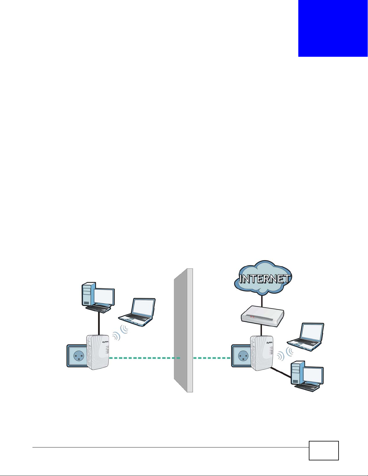
1.2 Expand Your Network with the PLA4231
The PLA4231 plugs into an ordinary power outlet to easily extend a cable or DSL broadband
connection or existing Ethernet (LAN) network to any other electrical outlet in any room of a house,
all without the need for any new cabling. Devices can securely communicate with each other at high
data transfer rates. The PLA4231 uses 128-bit Advanced Encryption Standard (AES) to ensure safe
transfer of information.
Figure 1 Expand Your Network with the PLA4231
Connect your PLA4231 to an Internet gateway such as a modem and plug it into an ordinary power
outlet in your home. Plug a second PLA4231 into another power outlet and connect a computer to
the PLA4231 for Internet access. You can also connect a computer to your existing wireless network
through the PLA4231 which acts as an AP or wireless extender. Your network can be further
PLA4231 User’s Guide 9

Chapter 1 Introducing the PLA4231
expanded by plugging additional PLA4231s into other outlets in your home and connecting other
computers or network devices (for example, a printer) to them.
Refer to your Quick Start Guide for hardware connection information.
1.3 Ways to Manage the PLA4231
•Use the RESET/ENCRYPT button to add powerline devices to your powerline network if they
have this button. See Chapter 3 on page 15 for instructions on using the ENCRYPT feature.
•Use the PLA42xx Series Configuration Utility (or utility, for short) to manage the PLA4231.
See Chapter 4 on page 23 for instructions on installing the utility.
Note: This User’s Guide describes the latest version utility. This utility is only compatible
with a PLA4231 which has the latest firmware installed. If you don’t already have
them, download the latest firmware and utility from the ZyXEL website.
• Use the Web Configurator for everyday management of the PLA4231 using a (supported) web
browser. See Section 7.2 on page 49 for instructions on accessing the Web Configurator.
• WPS (Wi-Fi Protected Setup) button. You can use the WPS button or the WPS section of the Web
Configurator to set up a wireless network with your PLA4231. See Section on page 13 for
instructions on using the WPS button.
1.4 Good Habits for Managing the PLA4231
Do the following things regularly to make the PLA4231 more secure and to manage the PLA4231
more effectively.
• Change the password. Use a password that’s not easy to guess and that consists of different
types of characters, such as numbers and letters.
• Write down the password and put it in a safe place.
• Back up the configuration (and make sure you know how to restore it). Restoring an earlier
working configuration may be useful if the device becomes unstable or even crashes. If you
forget your password, you will have to reset the PLA4231 to its factory default settings. If you
backed up an earlier configuration file, you would not have to totally re-configure the PLA4231.
You could simply restore your last configuration.
1.5 Powerline Security
Since your powerline network may extend outside your premises, it is important to set up security
on your PLA4231.
10
PLA4231 User’s Guide

1.5.1 Powerline Passwords
You use two types of passwords in the HomePlug AV powerline network. The following table
describes the differences between the passwords.
Table 1 Powerline Password Summary
PASSWORD DESCRIPTION
Network Name All powerline adapters that follow the HomePlug AV standard are shipped with the
same powerline network name “HomePlugAV”. Change the network name via the
PLA42xx Series Configuration Utility to create a private network. See Section
5.3 on page 29.
DAK (Data Access Key)
Password
In order to manage the powerline adapters on your powerline network you must
enter the adapters’ DAK password in the PLA42xx Series Configuration Utility.
This password is printed on the powerline adapter itself.
You don’t need to add the password for the powerline adapter directly connected to
the computer running the configuration utility (local powerline adapter), you only
have to add the remote powerline adapters’ passwords (those on your circuit, but
not directly connected to your computer).
1.5.2 Setting Up Powerline Security
Chapter 1 Introducing the PLA4231
The ENCRYPT feature automatically sets up security on your powerline network. Use this feature if
your powerline devices have the RESET/ENCRYPT button.
If your devices do not have the RESET/ENCRYPT button, use the PLA42xx Series
Configuration Utility to set up security on the PLA4231. Although the PLA4231 is a “plug-andplay” network expanding solution there are several reasons for enabling security on the powerline
network in your home.
1 It’s easy and only requires you to change a network name.
2 It’s a good idea to ensure privacy of your communication. When you use the PLA4231 and other
powerline adapters, the electrical wiring in your home becomes an extension of your Ethernet
network. Your network traffic flows freely within the electrical circuit of your home and is bounded
in most cases by a power meter.
Without security (encryption) your information is accessible to anyone using a powerline adapter on
the same electrical circuit. In some cases, a circuit can be shared by more than one household.
To prevent compromising your network security, you can create a private network. A private
network uses a secret password (Network Name) to make sure that only permitted powerline
adapters can communicate in your network. See Section 5.3 on page 29 for information on setting
up a private network.
3 You may need to change the Network Name to create multiple powerline networks. See the next
section for more information on how to set up a multiple network.
PLA4231 User’s Guide
11

Chapter 1 Introducing the PLA4231
1.6 Multiple Networks
Multiple powerline networks can coexist on a single powerline circuit. You might want to implement
multiple powerline networks in a small office environment where you have two separate Ethernet
networks.
1 Connect one powerline adapter to a router or switch on the first Ethernet network and assign a
Network Name (for example “Password1”) to this powerline adapter. Add additional powerline
adapters to your network by plugging them into your powerline outlets and assigning them
“Password1”. This completes the configuration of your first powerline network.
2 Connect another powerline adapter to a router or switch on the second Ethernet network and
assign a different Network Name (for example “Password2”) to this powerline adapter. Again, add
additional powerline adapters and assign them “Password2”.
You now have two private networks on your powerline circuit. Information is not shared between
the two networks as only powerline adapters with the same Network Name can communicate with
each other.
1.7 Resetting the PLA4231
If you forget your password or IP address, or you cannot access the Web Configurator, you will need
to use the RESET/ENCRYPT button at the side of the PLA4231 to reload the factory-default
configuration file. This means that you will lose all configurations that you had previously saved, the
password will be reset to “1234” and the IP address will be reset to “192.168.1.2”.
1.7.1 Procedure to Use the Reset Button
1 Make sure the power LED is on.
2 Press the RESET button for 10 to 15 seconds (until the power LED begins to blink) and release it to
set the PLA4231 back to its factory-default configurations.
12
PLA4231 User’s Guide

2.1 WPS Overview
Your PLA4231 supports Wi-Fi Protected Setup (WPS), which is an easy way to set up a secure
wireless network. WPS is an industry standard specification, defined by the Wi-Fi Alliance.
WPS allows you to quickly set up a wireless network with strong security, without having to
configure security settings manually. Each WPS connection works between two devices. Both
devices must support WPS (check each device’s documentation to make sure).
Depending on the devices you have, you can either press a button (on the device itself, or in its
configuration utility) or enter a PIN (a unique Personal Identification Number that allows one device
to authenticate the other) in each of the two devices. When WPS is activated on a device, it has two
minutes to find another device that also has WPS activated. Then, the two devices connect and set
up a secure network by themselves.
CHAPTER 2
The WPS Button
2.2 How to Use the WPS Button
You can use the WPS button on the side panel of the PLA4231 to activate WPS.
1 Make sure the power LED and the WLAN LED are on (not blinking).
2 To copy wireless settings (SSID and wireless security key for example) from an access point (AP) or
wireless router, press the WPS button for longer than five seconds and release it. The WLAN LED
begins to blink.
To connect a WPS-enabled wireless client (such as your computer with a WPS-enabled wireless
adapter) to the PLA4231 via Wi-Fi or to the existing wireless network through the PLA4231, press
the WPS button for two or three seconds and release it. The WLAN LED begins to blink.
3 Press the WPS button on another WPS-enabled device within range of the PLA4231.
4 The WLAN LED turns steady on when WPS was successful. The WLAN LED will be off for about ten
seconds if WPS has failed, and comes on again.
Note: You must activate WPS in the PLA4231 and in another wireless device within two
minutes of each other.
PLA4231 User’s Guide 13

Chapter 2 The WPS Button
14
PLA4231 User’s Guide

CHAPTER 3
The RESET/ENCRYPT Button
Use the RESET/ENCRYPT button to automatically set up a secure powerline connection between
your powerline devices.
3.1 RESET/ENCRYPT Button Overview
The RESET/ENCRYPT button allows you to set up a secure powerline connection with other
HomePlug AV compliant powerline devices which also support the ENCRYPT feature. No other
powerline setting changes are required to connect.
You can use the RESET/ENCRYPT button to:
• set up a new powerline network.
• separate an existing powerline network into multiple networks.
• reset the PLA4231 to the factory defaults.
3.2 Set Up a HomePlug AV Network with ENCRYPT
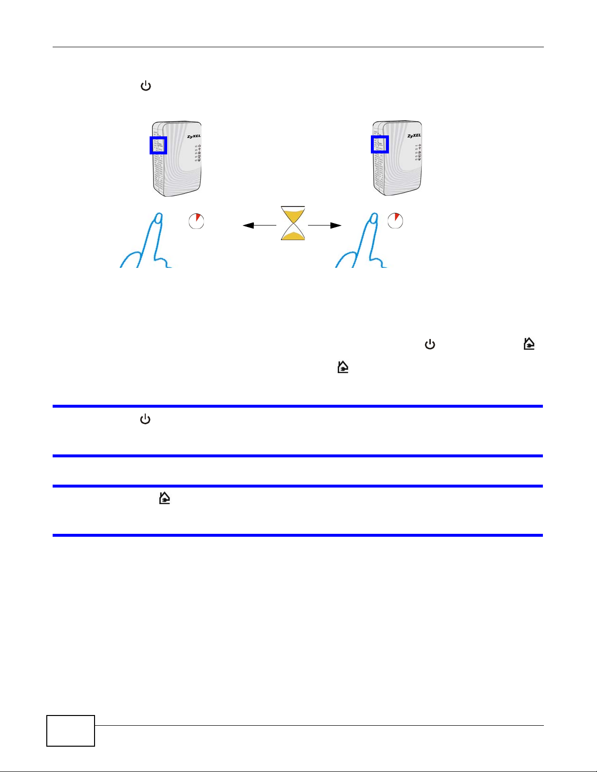
You can connect a number of devices on a powerline network, but you can use the RESET/
ENCRYPT button on only two devices at a time.
Place a powerline device close to another powerline device so you have time to set up each one.
After you set up the first powerline device, you have 120 seconds to set up the second powerline
device.
You can disconnect them from your computer or modem (or other networking equipment) if you
need to move them close to each other, but the powerline devices need to be plugged into power
outlets.
Follow the steps below to set up your HomePlug AV Network:
1 Press and hold the RESET/ENCRYPT button at the side of your powerline device for 5 to 8 seconds
and then release it. This resets the network name to a random value and removes your device from
any network it may belong to.
PLA4231 User’s Guide 15
Chapter 3 The RESET/ENCRYPT Button
press 0.5 ~ 3 seconds
press 0.5 ~ 3 seconds
within 2
minutes
2 Press the RESET/ENCRYPT button at the side of your powerline device for 0.5 to 3 seconds. The
power ( ) light will blink as the powerline device tries to set up a connection.
Figure 2 ENCRYPT Connection Procedure
Note: The RESET/ENCRYPT button’s location varies for each Powerline model.
3 Repeat step 2 in this section for the other powerline device you wish to connect. This must be done
within 120 seconds of pressing the RESET/ENCRYPT button on the PLA4231.
Note: Check the lights on the two powerline devices. The power ( ) and HomePlug ( )
lights should be blinking while the devices are connecting. Several times all lights
blink simultaneously and the HomePlug ( ) light also shows red. Wait for about
one minute while your powerline devices connect.
If the power ( ) light does not blink when you press RESET/ENCRYPT, you have probably
pressed the RESET/ENCRYPT button for too long. Try again, pressing the RESET/
ENCRYPT button for 0.5 to 3 seconds.
If the HomePlug ( ) lights on both powerline devices do not light up, the powerline
devices are not connected. Repeat steps 2 and 3 in this section. If that doesn’t work, see
the Troubleshooting in Section 14.5 on page 99 for suggestions.
4 To add more powerline devices to your network, press and hold the RESET/ENCRYPT button on
device C (shown below) for for 5 to 8 seconds and then release it.
16
PLA4231 User’s Guide
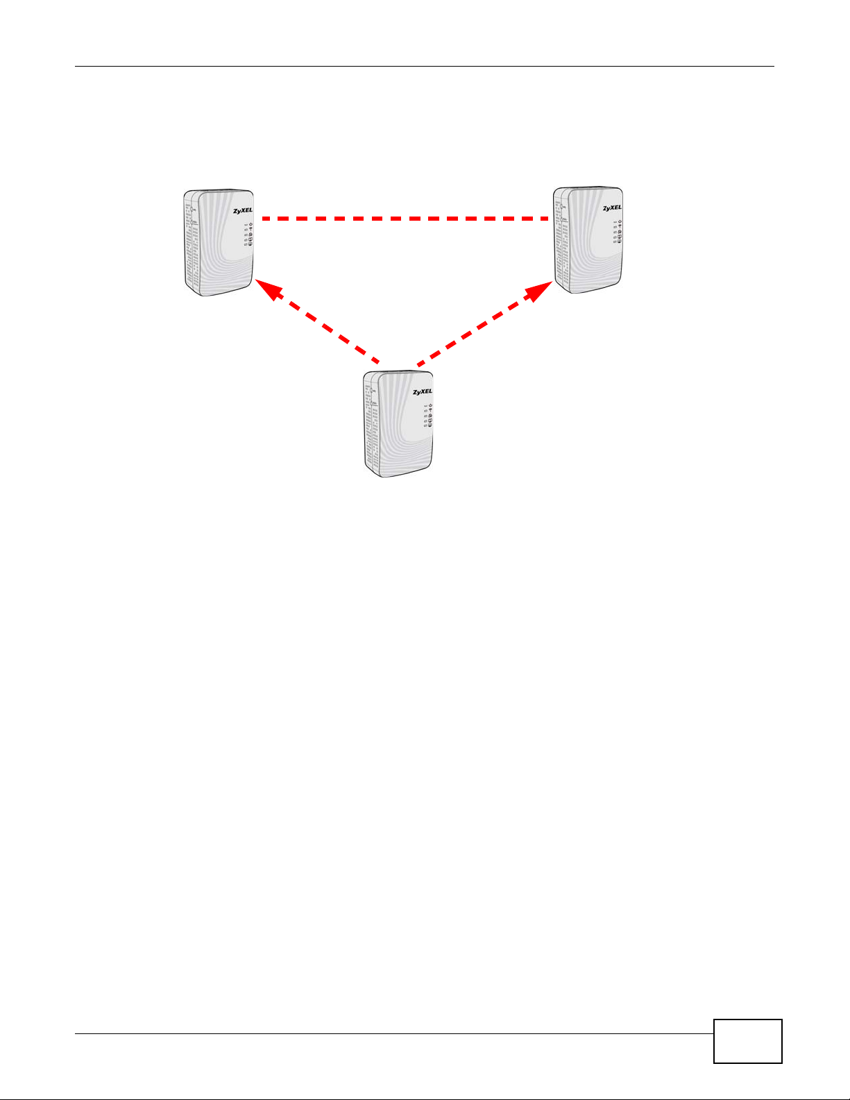
Chapter 3 The RESET/ENCRYPT Button
A
B
OR
C
AB
5 Then repeat steps 2 and 3 in this section using any powerline device (A or B) you have connected
using ENCRYPT and the powerline device you want to connect (C). You must use the RESET/
ENCRYPT button on both devices.
Figure 3 Adding More Powerline Adapters to Your Network
6 If you disconnected your computer or modem (or any other networking product connected to your
powerline device) in step of this section, you can now reconnect them.
This sets up your powerline network between your powerline devices.
3.3 Setting Up Multiple Networks
You can use the RESET/ENCRYPT button to set up multiple powerline networks using your
existing powerline network.
PLA4231 User’s Guide
17
Chapter 3 The RESET/ENCRYPT Button
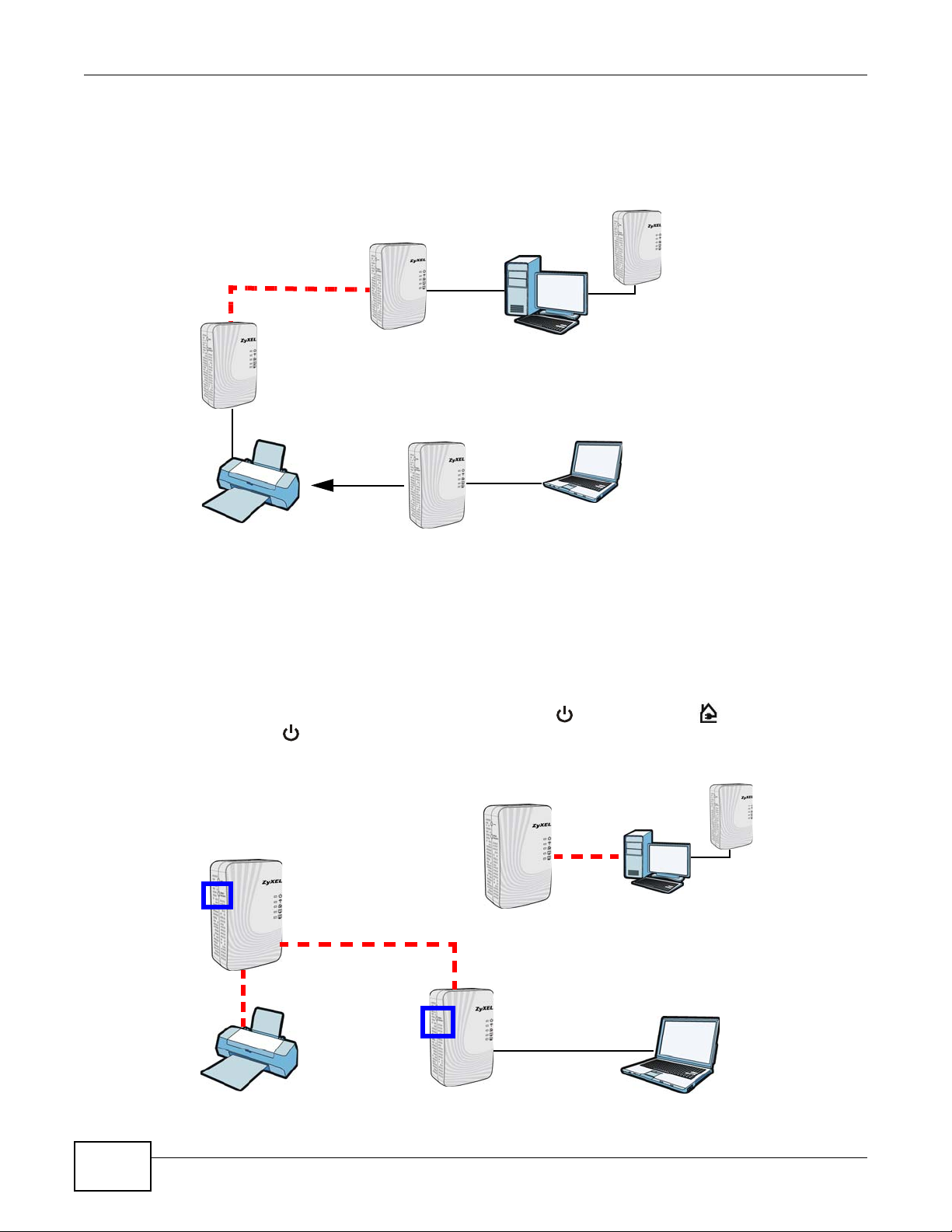
A
C
B
A
C
B
For example, you have already set up a powerline network in your home (A) which accesses a
printer (B). Now you want a separate powerline network connection from your laptop to your
printer (C).
Figure 4 One Existing Powerline Network
1 Click the RESET/ENCRYPT button on (A) for 5 to 8 seconds and then release it. This disconnects
(A) from (B).
2 Click the RESET/ENCRYPT button on (A) and (C) for 0.5 to 3 seconds and within two minutes of
each other.
3 Wait for about one minute while (A) and (C) connect.
4 Check the LEDs on both (A) and (C). When the power ( ) and HomePlug ( ) lights stop blinking
and the power ( ) light shines steadily, the devices are connected.
Figure 5 Two Separate Powerline Networks
18
PLA4231 User’s Guide
Chapter 3 The RESET/ENCRYPT Button
Congratulations. You now have two separate powerline networks as shown above.
If the HomePlug ( ) lights on both powerline devices do not light up, the powerline
devices are not connected. Repeat the connection process, making certain you press the
RESET/ENCRYPT buttons for the correct time and within two minutes of each other. If that
does not work see Section 14.5 on page 99 for suggestions.
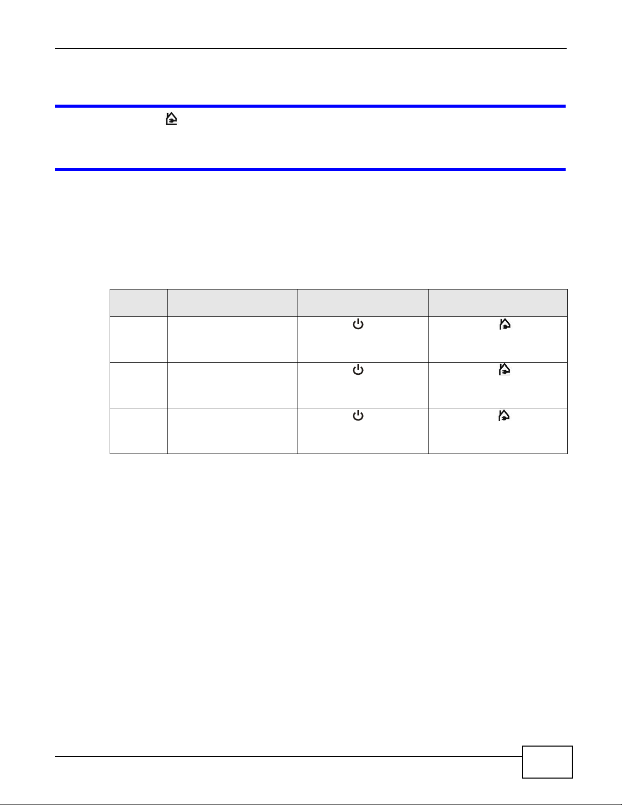
3.4 RESET/ENCRYPT Button Behavior
The following table summarizes the actions that occur when the RESET/ENCRYPT button is
pressed for specific lengths of time.
Table 2 Time RESET/ENCRYPT Button is Pressed and Action
TIME ACTION POWER LIGHT BEHAVIOR
0.5 to 3
seconds
5 to 8
seconds
10 to 15
seconds
The device joins a network. It
shares the same network
name as other devices on the
network.
The device leaves any
network it is associated with
and its network name
assumes a random value.
Clear all user-entered
configuration information and
return the device to its
factory defaults.
The power ( ) light blinks
until the device is connected.
This may take a minute.
The power ( ) light blinks
several times and then shines
steadily.
The power ( ) light blinks
several times and then shines
steadily.
HOMEPLUG LIGHT
BEHAVIOR
The HomePlug ( ) light turns
on if your device is connected
to another powerline device or
a powerline network.
The HomePlug ( ) light blinks
red one time and then turns off
when it disconnects from the
powerline network.
The HomePlug ( ) light blinks
red one time and then turns off
when it disconnects from the
powerline network.
See Troubleshooting in Chapter 14 on page 99 for suggestions on problems with the RESET/
ENCRYPT button and the lights.
PLA4231 User’s Guide
19

Chapter 3 The RESET/ENCRYPT Button
20
PLA4231 User’s Guide

PART II
Configuration Utility
21

22

CHAPTER 4
Installing the Powerline Configuration Utility
This chapter guides you through the installation of the configuration utility for your PLA4231.
4.1 Overview of the Installation Process
The installation of the configuration utility does the following:
1 Checks for and installs Microsoft’s .NET Framework version 2.0 software on your computer. This
software is necessary for the installation of the PLA42xx Series Configuration Utility. If you
already have .NET Framework version 2.0 installed on your computer this step will be skipped.
Note: At the time of writing the Utility is only compatible with Microsoft Windows XP,
Microsoft Windows Vista (32-bit version), Microsoft Windows 7 and Microsoft
Windows 8 operating systems. Users with Windows XP (64-Bit version) operating
systems can go to Microsoft’s website to upgrade their systems to .NET Framework
version 2.0 so it can work with the utility. To check for your Windows operating
system version, right-click on My Computer > Properties. You should see this
information in the General tab.
2 Installs ZyXEL’s PLA42xx Series Configuration Utility. This utility allows you to manage the
network name (See Section 5.3 on page 29 for more information) or view the devices recognized
on your powerline network.
Note: This User’s Guide describes the latest version utility. This utility is only compatible
with a PLA4231 which has the latest firmware installed. If you don’t already have
them, download the latest firmware and utility from the ZyXEL website.
4.2 Installing the Utility
Follow the steps below to install .NET Framework version 2.0 and the PLA42xx Series
Configuration Utility on your computer.
PLA4231 User’s Guide 23
Chapter 4 Installing the Powerline Configuration Utility
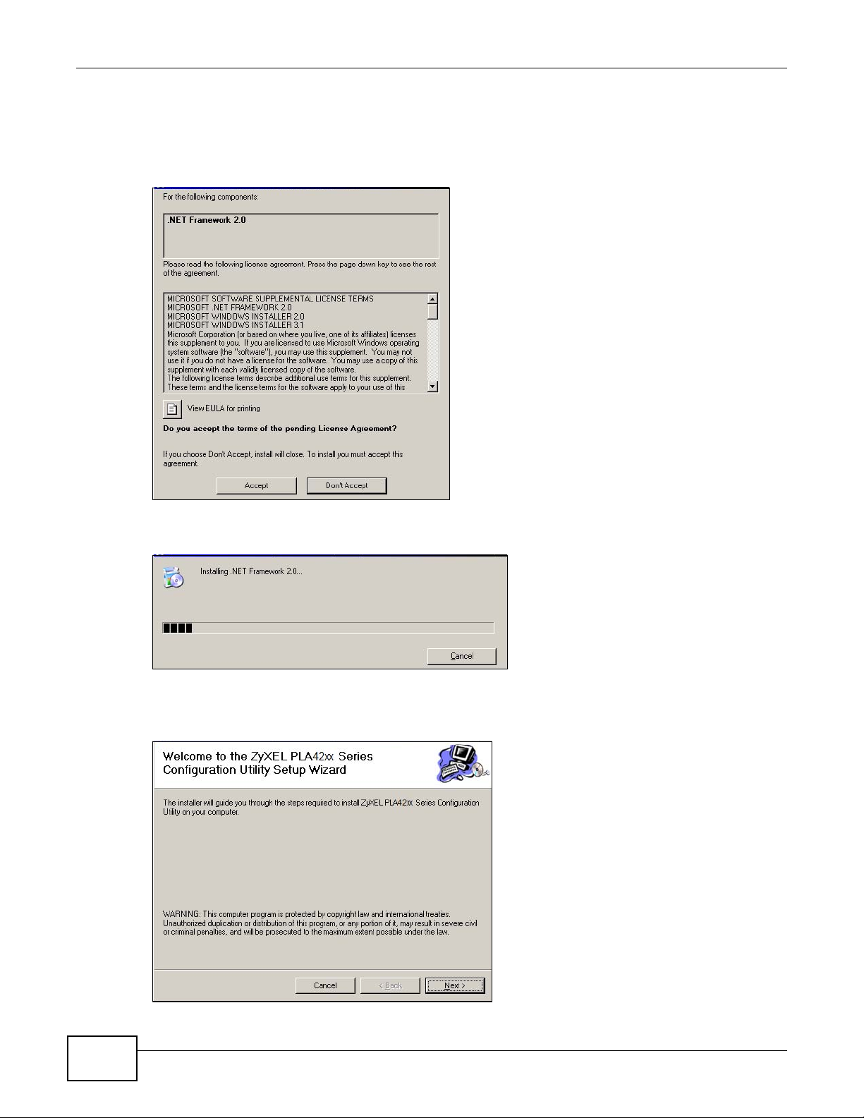
1 Insert the included CD-ROM into your computer’s CD-ROM drive. The Setup utility runs
automatically. Alternatively this can also be done manually by double clicking the setup.exe file on
the CD. A prompt appears asking you to install the .NET Framework version 2.0. Review Microsoft’s
License Agreement, select Accept to proceed.
Figure 6 .NET Framework Installation Prompt
2 The next screen allows you to see the progress of the installation.
Figure 7 .NET Framework Installation Process
3 The Setup utility runs automatically. Click Yes or Next to continue through the initial screen. Click
Cancel only if you want to abort the installation.
Figure 8 InstallShield Wizard Start Screen
24
PLA4231 User’s Guide
Chapter 4 Installing the Powerline Configuration Utility
4 If you want the utility to be only available to the currently logged in user, select Just me.
Otherwise, click Everyone to allow all users to use the configuration utility. Click Next to install the
utility to the default folder, or click Browse to specify a different location on your computer.
Figure 9 Install Destination Folder
Note: You can also click Disk Cost to know how much available disk space you have in
the hard drives found in your computer.
5 When the installation is finished, a screen appears to confirm the InstallShield Wizard has
successfully installed the PLA42xx Series Configuration Utility to your computer. Click Close to
exit the wizard.
Figure 10 Installation Complete
Note: You may be asked to restart your computer when the installation is complete. Click
“Yes” to restart your computer. If you select “No, I will restart my computer later”,
you will not be able to launch the utility until after a restart of your computer.
PLA4231 User’s Guide
25

Chapter 4 Installing the Powerline Configuration Utility
26
PLA4231 User’s Guide
Using the Powerline Configuration Utility
A
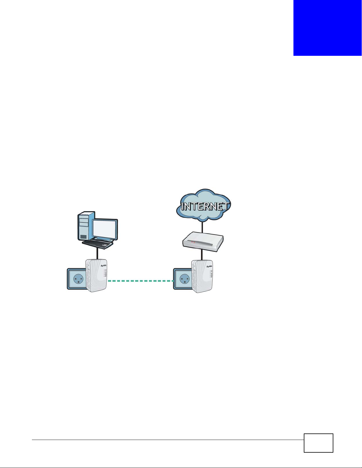
5.1 Overview
This chapter shows you how to use the Configuration Utility (or Utility) to secure, manage and set
up Quality of Service (QoS) on your powerline network.
The PLA4231 is designed as a plug-and-play network expanding solution. This means that once you
complete your hardware connections, the PLA4231s in your network (without additional
configuration) are able to communicate with each other by sending and receiving information over
your home’s electrical wiring (A).
Figure 11 Example Network Setup
CHAPTER 5
All HomePlug AV compliant powerline adapters within range can join your network. The range
varies depending on the quality of your home’s wiring.
Note: See Section 5.1.1 on page 27 for more information on enhancing your powerline
network security.
5.1.1 Powerline Network Security
When the PLA4231s communicate with each other, they use encryption to protect the information
that is sent in the powerline network. Encryption is like a secret code. If you do not know the secret
code, you cannot understand the message. The HomePlug AV standard uses 128-bit AES (Advanced
Encryption Standard) to safely transmit data between powerline adapters.
For the powerline adapters to communicate with each other they all need to use the same network
name. This network name allows the powerline adapters to understand the encrypted information
sent in the powerline network.
PLA4231 User’s Guide 27

Chapter 5 Using the Powerline Configuration Utility
By default the PLA4231s are all configured with the network name HomePlugAV, this allows you to
simply plug the devices in and not worry about setting up security. If you want to enhance the
security on your powerline network, you can change the network name on the powerline adapters
you want to allow to communicate in your powerline network.
5.1.2 Device Access Key (DAK)
In order to manage the powerline adapters on your powerline network you must enter the adapters’
password in the PLA42xx Series Configuration Utility. This password is called the DAK (Device
Access Key) password. This password is printed on the powerline adapter itself.
You don’t need to enter the DAK password for the powerline adapter directly connected to the
computer running the utility (local powerline adapter), you only have to add the remote powerline
adapters’ passwords (those in your powerline network, but not directly connected to your
computer).
5.2 Starting the Configuration Utility
To launch the PLA42xx Series Configuration Utility simply double click on the configuration icon
on your desktop.
Figure 12 PLA42xx Series Configuration Utility Icon
Alternatively, start the utility by browsing to it from the start menu. Click Start > Programs >
ZyXEL PLA42xx Series Configuration > PLA42xx Series Configuration.
28
PLA4231 User’s Guide
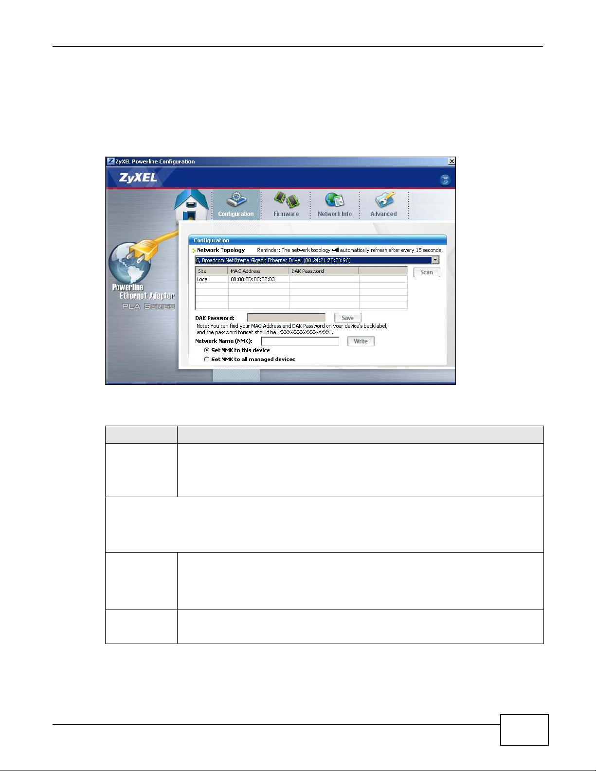
5.3 Configuration Screen
Use the Configuration screen to see which devices are recognized by your powerline network, to
configure your PLA4231 and to set up a secure powerline network by changing the powerline
network name. This screen opens up when you launch the utility.
Figure 13 Configuration Screen
Chapter 5 Using the Powerline Configuration Utility
The following table describes the labels in this screen.
Table 3 Configuration Screen
LABEL DESCRIPTION
Network
Topology
The fields described below are used to identify the powerline adapters recognized on the powerline network.
The configuration utility automatically updates this information every 10 seconds. Click Scan to refresh the
information in these fields (immediately).
Use this to select which powerline network information is displayed. Different powerline
networks are identified by the Ethernet interface (network card) on your computer which is
connected directly to a powerline adapter. Typically there is only one connection. However,
if your computer has two network cards and both are connected to a powerline adapter,
then you have two powerline networks.
Note: Only devices which share the same network name are displayed in this table.
Site This field displays
• Local, if it is identifying the powerline adapter directly connected to the computer
running the configuration utility.
• Remote, if it is a powerline adapter in your powerline network but not directly
connected to the computer running the configuration utility.
MAC Address This is a read-only field which shows the MAC address of the powerline adapter you are
configuring. You can find the MAC address of your PLA4231 displayed on a sticker on the
bottom of your device.
PLA4231 User’s Guide
29

Chapter 5 Using the Powerline Configuration Utility
Table 3 Configuration Screen (continued)
LABEL DESCRIPTION
DAK Password DAK (Device Access Key) password is used to verify that you are authorized to perform
changes on a remote device. You can find the DAK password printed on a sticker on the
bottom of your PLA4231.
Select the remote powerline adapter you want to manage by clicking the MAC address
which corresponds to it in the MAC Address column. Enter the DAK Password value and
click Save.
Note: You must enter the DAK Password value exactly as it is printed on the label (all caps
and with dashes “-”).
Network Name
(NMK)
Set NMK to this
device
Set NMK to all
devices
Save Click this to apply your changes. The new Network Name is applied to the selected
The default network name (sometimes called a network password or network membership
key (NMK)) of the PLA4231 is “HomePlugAV”. HomePlug compatible devices use the same
network name to recognize and communicate with each other over the powerline network.
If you change the network name of one device on the network, it will no longer be
recognized as part of that network.
If you change the network name, make sure you change the network name for all of the
powerline adapters that you want to be part of your powerline network.
The network name can be from 8 to 64 characters in length, using “A”~”Z”, “a”~”z”,
“0”~”9”; spaces are not allowed.
Select this to apply the NMK (entered in the field above) as the network name for the
powerline adapter directly connected to the computer running the configuration utility.
Select this to apply the NMK (entered in the field above) as the network name for all
powerline adapter detected by the utility.
powerline adapter.
Note: You must enter the correct DAK password for the selected powerline adapter before
you can make changes to it.
5.4 Firmware Screen
Use the Firmware screen to update the firmware on the PLA4231 directly connected to the
computer running the configuration utility.
Firmware is the software which is embedded in the PLA4231. This software contains processing
instructions for how the PLA4231 sends and receives information in a secure way.
Parameter Information Block (PIB) is similar to firmware. It contains the most basic operating
instructions for the PLA4231 such as how to power up and how to load the firmware.
You can check the ZyXEL website for firmware upgrades for your PLA4231.
Note: If you have upgraded the firmware, make sure you also upgrade the PLA42xx
Series Configuration Utility. Older version utilities are not compatible with
PLA4231s using the latest firmware.
30
PLA4231 User’s Guide

Chapter 5 Using the Powerline Configuration Utility
Note: Be sure to upload the correct model firmware as uploading the wrong model
firmware may damage your device.
Figure 14 Firmware Screen
5.5 Network Info Screen
Use the Network Info screen to see the rates at which a specific PLA4231 is communicating with
other powerline adapters on your powerline network.
Figure 15 Network Info Screen
PLA4231 User’s Guide
31

Chapter 5 Using the Powerline Configuration Utility
The following table describes the labels in this screen.
Table 4 Network Info Screen
LABEL DESCRIPTION
Adapter This field identifies which powerline network information is displayed. Different powerline
Central
Coordinator
MAC
The information provided in the following table reflects transmission rate information about the powerline
adapters which communicate in your powerline network.
The powerline adapters listed in this table are all the powerline adapters in your powerline network except the
powerline adapter selected in the Configuration page of the configuration utility. In other words, if the Local
powerline adapter is selected in the Configuration screen, then this table will display the rates of
transmission from the powerline adapter connected to the computer running the configuration utility to all the
Remote powerline adapters.
Site This field displays:
MAC Address This field displays the MAC address of your powerline adapter. The MAC address of your
Tra nsmi t Ra te
(Mbps)
Receive Rate
(Mbps)
networks are identified by the Ethernet interface (network card) on your computer which is
connected directly to a powerline adapter. Typically there is only one connection. However,
if your computer has two network cards and both are connected to a powerline adapter,
then you have two powerline networks.
The Central Coordinator of the powerline network is the powerline adapter which keeps
track of which devices are part of the network as well as synchronizes communication
within the powerline network. If the Central Coordinator is removed from the powerline
network then another powerline adapter takes its place. This field displays the MAC address
of the PLA4231 which is the Central Coordinator of the powerline network. The powerline
adapters in your powerline network automatically select the Central Coordinator.
• Local, if it is the PLA4231 directly connected to the computer running the configuration
utility.
• Remote, if it is a PLA4231 in your powerline network but not directly connected to the
computer running the configuration utility.
powerline adapter can be found by looking at the label on your device. It consists of six
pairs of hexadecimal characters (hexadecimal characters are “0-9” and “a-f”). In the case
of the PLA4231, this label is on the bottom of the device.
This field displays how fast information is sent from the powerline adapter selected in the
Configuration screen to this powerline adapter. The rate is given in the following format:
“application data transmission rate / raw data transmission rate”. Application data reflects
more accurately how fast devices are transmitting application relevant traffic (for example
Internet Protocol (IP) traffic). Raw data refers to the whole payload of the packets
transmitted across the powerline network.
This field displays how fast information is received from the powerline adapter selected in
the Configuration screen to this powerline adapter. The rate is given in the following
format: “application data transmission rate / raw data transmission rate”. Application data
reflects more accurately how fast devices are transmitting application relevant traffic (for
example Internet Protocol (IP) traffic). Raw data refers to the whole payload of the packets
transmitted across the powerline network.
5.6 Advanced Screen
Note: This feature is only available with the latest version utility. Go to the ZyXEL website
to download the latest utility and firmware for your ZyXEL HomePlug AV adapter.
You can configure the powerline adapters on your network to give priority to network traffic
depending on its importance. When you set the priority of a powerline adapter, you set how quickly
messages FROM your powerline adapter are sent in your powerline network. Transmissions TO your
powerline adapter do not receive any priority.
32
PLA4231 User’s Guide

Chapter 5 Using the Powerline Configuration Utility
A
B
C
D
E
For example, if you have a file server on your home network to deliver music and movie files to
computers in your home, you should set the priority of the powerline adapter connected to this
server to Medium. If video traffic is delivered too slowly, quality problems may occur.
On the other hand, a powerline adapter attached to a printer should have a low priority setting
since the slow delivery of messages will not affect the print job.
Similarly, if you want to prioritize any downloads from the Internet, set the priority on the powerline
adapter attached to your Internet gateway to High.
Allocate priority settings based on application type as follows.
Table 5 Priority Settings
PRIORITY LEVEL APPLICATION
High Voice Application
Medium Video and Audio Applications
Normal Data Applications
Low Data Applications
The figure below shows an example powerline home network connected to the Internet.
• Device A is a printer and does not handle traffic with high importance, so the powerline adapter
connected to it can be set to low priority.
• Device B is a file server, delivering audio or movie files to other users on the network. The
powerline adapter attached to it should have a medium setting.
• Device C, a home computer which connects to the Internet, can receive a normal priority setting
as it usually sends simple requests for data. For example, when you surf the Internet, your
computer sends requests to open web pages.
• Device D is a modem attached to the Internet. It should receive a high priority setting if you want
faster downloading through your network.
• Although device E receives audio or movie files, it does not send a lot of traffic, so the powerline
adaptor attached to it can be set to a low priority.
Figure 16 Priority Settings
PLA4231 User’s Guide
33

Chapter 5 Using the Powerline Configuration Utility
Use this screen to configure priority settings for traffic from the powerline adapters on your
network.
Figure 17 Advanced Screen
The following table describes the labels in this screen.
Table 6 Advanced Screen
LABEL DESCRIPTION
Adapter This field identifies which powerline network information is displayed. Different powerline
networks are identified by the Ethernet interface (network card) on your computer which is
connected directly to a powerline adapter. Typically there is only one connection. However, if
your computer has two network cards and both are connected to a powerline adapter, then
you have two powerline networks.
Site This field displays:
• Local, if it is the PLA4231 directly connected to the computer running the configuration
utility.
• Remote, if it is a powerline adapter in your powerline network but not directly connected
to the computer running the configuration utility.
MAC Address This is a read-only field which shows the MAC address of the powerline adapter you are
configuring. You can find the MAC address of your PLA4231 displayed on a sticker on the
bottom of your device.
Priority Select a priority setting from the drop-down box for traffic FROM your selected device. The
options, in order of importance, are High, Medium, Normal and Low.
Save Click this to apply your changes. The new Priority setting is applied to the selected
powerline adapter.
34
PLA4231 User’s Guide

5.7 About Screen
Use the About screen to view information regarding the configuration utility and firmware version
of the PLA4231 you are connected to. Click the icon in the top right corner of the utility to view
the About screen.
Figure 18 About Screen
Chapter 5 Using the Powerline Configuration Utility
The following table describes the labels in this screen.
Table 7 About Screen
LABEL DESCRIPTION
Utility version: This field displays the software version of the configuration utility.
Firmware version This field displays the firmware version of the device you selected in the Device Selection
field of the Configuration screen.
In the example firmware version given in the screen, 1.0.0.337, the firmware version is
shown by the numbers 1.0.0, meaning this is firmware version 1.0.0.
Released This field displays the date when the firmware was released.
Close Click the button in upper right corner to close the About window.
PLA4231 User’s Guide
35

Chapter 5 Using the Powerline Configuration Utility
36
PLA4231 User’s Guide

6.1 Overview
Use this tutorial to expand your existing powerline network.
After setting up your first home powerline network (instructions for that are in the Quick Start
Guide for your ZyXEL powerline adapter) you may want to extend the network or create a new one
by adding additional powerline adapters. This tutorial shows you the following.
• How to start up your new powerline adapter. You need to do this before you can begin the next
sections.
• How to make your existing powerline network bigger by adding new powerline adapters.
• How to make a new network separate from your existing network with new powerline adapters.
• How to make a new, separate powerline network with the powerline adapters you have.
CHAPTER 6
Powerline Network Setup Tutorial
The tutorial uses the PLA42xx Series Configuration Utility to set up your powerline adapter.
If you haven’t already installed the utility, see Chapter 4 on page 23 for instructions. If you do not
have the CD with the utility, the utility software is also available for download at www.zyxel.com.
Navigate to the powerline products section of the ZyXEL website to find this software. Follow the
instructions provided by the software to install it on your computer.
See the product specifications in the User’s Guide for a list of hardware and software compatible
with the utility.
Note: The PLA4231 in this tutorial is an example only. Your powerline adapter may be
different.
6.2 Important Terms
Network Name The network name allows a powerline adapter to connect with other powerline
DAK Password DAK = Device Access Key.
adapters that have the same network name. It provides security for your powerline
network. The network name uses English letters or numbers, from 8 to 64
characters long, with no spaces allowed.
The DAK Password lets you access the powerline adapter. You can find the DAK
Password on a label on your powerline device.
PLA4231 User’s Guide 37

Chapter 6 Powerline Network Setup Tutorial
1
2
3
6.3 Accessing Your Powerline Adapter
1 Plug the powerline adapter you want to add to your network into a power socket and, if needed,
switch the power socket on.
Figure 19 Plug Your Powerline Adapter into a Power Socket
2 Connect the powerline adapter to your computer.
3 Use a LAN or Ethernet cable (shown below) to connect the LAN or Ethernet port on your adapter to
the same kind of port on your computer.
Figure 20 Connect Your Powerline Adapter to a Computer
4 Open the PLA42xx Series Configuration Utility on your computer. Go to Start > (All)
Programs > ZyXEL PLA42xx Series Configuration > PLA42xx Series Configuration Utility,
or click on the icon on your desktop shown below.
Figure 21 Click on the PLA42xx Series Configuration Utility Icon
5 You are now ready to extend your powerline network or set up a second network.
•See Section 6.4 on page 39 to add a new powerline adapter to your network.
•See Section 6.5 on page 40 to set up a second network with your new adapters.
•See Section 6.6 on page 42 to set up a second network with your existing adapters.
38
PLA4231 User’s Guide

6.4 Adding a Powerline Adapter
A
B
This section shows you how to add a new powerline adapter to expand your existing network.
The figure below shows the family computer with Internet access on a powerline network. Expand
the network by adding a new powerline adapter connected to a printer.
Figure 22 Add a Printer to Your Powerline Network
Chapter 6 Powerline Network Setup Tutorial
Note: You do not need to know the network name of the new adapter to add it to your
network.
1 Connect your computer to the powerline adapter you want to add to your network and open the
PLA42xx Series Configuration Utility (see Section 6.3 on page 38).
2 The utility should open to the configuration tab. On this screen in the Site column your new
powerline adapter should appear as Local (A). Check the Local adapter’s MAC address (B). It
should match the MAC address listed on the label on the back of your powerline adapter.
Figure 23 Adding a New Adapter
PLA4231 User’s Guide
39

Chapter 6 Powerline Network Setup Tutorial
C
3 Select your adapter by selecting Local and type the network name for your existing network in the
Network Name field (C).
Figure 24 Adding an Adapter to an Existing Network
4 Click Save and click OK on the pop-up.
Figure 25 Network Name Pop-up
5 Your new adapter will now have the same Network Name as your existing network and so has
now joined your existing network.
6 Connect the adapter to the device you want to add to the network, for example, your Internet
refrigerator in the kitchen.
7 Plug the adapter’s power cord into a power outlet and, if required, switch the power outlet on.
8 Repeat this procedure for all additional powerline adapters that you want to add to your existing or
new powerline network.
6.5 Setting Up a New Network with a New Adapter
This section shows you how to use your new powerline adapters to set up a new powerline network
separate to your existing network.
The figure below shows two powerline networks in a house. The first network (1) shows the home
computer connected to a printer and access to the Internet. The second network (2) has no
40
PLA4231 User’s Guide

Chapter 6 Powerline Network Setup Tutorial
Internet access but with a media adapter such as the ZyXEL DMA-1100P you can use your TV to
watch movies and play games which are stored on a computer.
Figure 26 Add New Adapters to Make a Second Network
1 Connect your new powerline adapter and open the configuration utility as shown in Section 6.5 on
page 40. The screen shown below appears.
2 Type a Network Name that is different from the Network Name for your existing network. Make
sure you use the same new Network Name for all new adapters you want to add to your new
network.
Figure 27 Making a New Network with the New Adapter
PLA4231 User’s Guide
41

Chapter 6 Powerline Network Setup Tutorial
3 After you have set up a new network, you are ready to connect each powerline adapter on your new
network to devices, for example, a computer or a games console.
6.6 Splitting a Network into Two Networks
This section shows you how to split your existing network into two networks. This is useful if you
want to set up a second powerline network in your home, for example, in your study connecting a
laptop and printer. See Figure 26 on page 41 for an example.
To set up your existing powerline network you had to set each powerline adapter with the same
network name. To move some of these adapters to a new network, you need to give them a new
network name.
1 Connect a powerline adapter to your computer and open the PLA42xx Series Configuration
Utility (see Section 6.3 on page 38).
2 The utility should open to the configuration tab as shown below. A list of powerline adapters on your
network displays. These adapters all have the same network name as the adapter you are
connected to. The adapter you are connected to will appear as Local in this table. All others are
listed as Remote.
Figure 28 Local/Remote Adapters on a Powerline Network
3 To set up a new powerline network, type the DAK Password and change the Network Name on
all powerline adapters you wish to add to your network.
• Look for the DAK Password on a label on your powerline adapter. The DAK Password lets
you access the adapter.
• Select the Remote adapter you want to add (A) and type the DAK Password in the DAK
Password field (B).
42
PLA4231 User’s Guide

Chapter 6 Powerline Network Setup Tutorial
B
A
• Then type the new network name in the Network Name field.
Figure 29 Adding an Adapter to Your New Network
4 Click Save.
• If you do not type the DAK password or type it incorrectly either of the following pop-ups
appear. Click OK and type the DAK Password correctly in the DAK Password field.
Figure 30 Incorrect DAK or No DAK
• If you have correctly entered the DAK Password, click OK on the pop-up.
Figure 31 Correct DAK
PLA4231 User’s Guide
43

Chapter 6 Powerline Network Setup Tutorial
5 The settings for the adapter will now grey out and the adapter will disappear from the table after a
few minutes.
Figure 32 An Adapter on Your New Network
6 Go back to step 3 in this section to set the same, new Network Name for all remote adapters you
want to add to your new network.
7 Check you have added the adapters correctly by changing the network name for the local adapter.
All adapters with the new Network Name now appear in the list of adapters on your network.
These adapters are now part of your new network.
Figure 33 Adapters on a New Powerline Network
• If you want to access any of your new powerline networks using the PLA42xx Series
Configuration Utility, change the Network Name on your local adapter to the network name
for the network you want to access. The adapters on that network will then display in the adapter
table, allowing you to select and configure each one.
6.7 Troubleshooting
The HomePlug ( ) LED (light) should light up on your adapter when it successfully connects to
other adapters on your network. If it does not, try the following measures.
• Make sure the adapter is plugged in to a power socket and the power socket is turned on.
44
PLA4231 User’s Guide

Chapter 6 Powerline Network Setup Tutorial
• Check you have entered the correct network name for your network.
• Check your powerline adapter is connected to the same electrical circuit as other powerline
adapters on your network.
PLA4231 User’s Guide
45

Chapter 6 Powerline Network Setup Tutorial
46
PLA4231 User’s Guide

PART III
Web Configurator
47

48

7.1 Overview
This chapter describes how to access the PLA4231 Web Configurator and provides an overview of its
screens.
The Web Configurator is an HTML-based management interface that allows easy setup and
management of the PLA4231 via Internet browser. Use Internet Explorer 6.0 and later or Safari 2.0
or later versions. The recommended screen resolution is 1024 by 768 pixels.
In order to use the Web Configurator you need to allow:
• Web browser pop-up windows from your device. Web pop-up blocking is enabled by default in
Windows XP SP (Service Pack) 2.
• JavaScripts (enabled by default).
• Java permissions (enabled by default).
CHAPTER 7
Introducing the Web Configurator
Refer to the Troubleshooting chapter (Chapter 14 on page 95) to see how to make sure these
functions are allowed in Internet Explorer.
7.2 Accessing the Web Configurator
1 Connect your computer to the LAN port of the PLA4231.
2 The default IP address of the PLA4231 is “192.168.1.2”. In this case, your computer must have an
IP address in the range between “192.168.1.3” and “192.168.1.254”.
Click Start > Run on your computer in Windows. Type “cmd” in the dialog box. Enter “ipconfig” to
show your computer’s IP address. If your computer’s IP address is not in the correct range then
change your computer’s IP address.
3 After you’ve set your computer’s IP address, open a web browser such as Internet Explorer and
type “http://192.168.1.2” as the web address in your web browser.
7.2.1 Login Screen
The Web Configurator initially displays the following login screen.
PLA4231 User’s Guide 49

Chapter 7 Introducing the Web Configurator
Figure 34 Login screen
The following table describes the labels in this screen.
Table 8 Login screen
LABEL DESCRIPTION
Language Select the language you want to use to configure the Web Configurator. Click Login.
Password Type "1234" (default) as the password.
7.2.1.1 Weather Edit
You can change the temperature unit and select the location for which you want to know the
weather.
Click the icon to change the weather display.
Figure 35 Change Weather
(This is just an example). This shows the current weather, either in celsius or fahrenheit,
of the city you specify in Section 7.2.1.1 on page 50.
(This is just an example). This shows the time (hh:mm:ss) and date (yyyy:mm:dd) of the
timezone you select in Section 7.2.1.2 on page 51 or Section 13.5 on page 88. The time is
in 24-hour format, for example 15:00 is 3:00 PM.
50
PLA4231 User’s Guide

The following table describes the labels in this screen.
Table 9 Change Weather
LABEL DESCRIPTION
o
C or oF Choose which temperature unit you want the PLA4231 to display.
Change Location Select the location for which you want to know the weather. If the city you want is not
Finish Click this to apply the settings and refresh the date and time display.
7.2.1.2 Time/Date Edit
One timezone can cover more than one country. You can choose a particular country in which the
PLA4231 is located and have the PLA4231 display and use the current time and date for its logs.
Click the icon to change the time and date display.
Figure 36 Change Time Zone
Chapter 7 Introducing the Web Configurator
listed, choose one that is closest to it.
The following table describes the labels in this screen.
Table 10 Change Time Zone
LABEL DESCRIPTION
Change time zone Select the specific country whose current time and date you want the PLA4231 to
display.
Finish Click this to apply the settings and refresh the weather display.
Note: You can also edit the timezone in Section 13.5 on page 88.
7.2.2 Password Screen
You should see a screen asking you to change your password (highly recommended) as shown
next.
Figure 37 Change Password Screen
PLA4231 User’s Guide
51

Chapter 7 Introducing the Web Configurator
A
B
C
The following table describes the labels in this screen.
Table 11 Change Password Screen
LABEL DESCRIPTION
New Password Type a new password.
Retype to Confirm Retype the password for confirmation.
Apply Click Apply to save your changes back to the PLA4231.
Ignore Click Ignore if you do not want to change the password this time.
Note: The management session automatically times out when the time period set in the
Administrator Inactivity Timer field expires (default five minutes; go to Chapter
13 on page 87 to change this). Simply log back into the PLA4231 if this happens.
Right after you log in, the Dashboard screen is displayed. See Chapter 4 on page 81 for more
information about the Dashboard screen.
7.3 Navigating the Web Configurator
The following summarizes how to navigate the web configurator from the Dashboard screen.
Figure 38 Status Screen of the Web Configurator
52
As illustrated above, the Web Configurator screen is divided into these parts:
PLA4231 User’s Guide

• A - title bar
• B - navigation panel
• C - main window
7.3.1 Title Bar
Click Logout at any time to exit the Web Configurator.
Click About to open the about window, which provides information of the boot module and driver
versions.
7.3.2 Navigation Panel
Use the menu items on the navigation panel to open screens to configure PLA4231 features. The
following tables describe each menu item.
Table 12 Navigation Panel: Access Point Mode
LINK TAB FUNCTION
Dashboard This screen shows the PLA4231’s general device, system and interface
MONITOR
Log Use this screen to view the list of activities recorded by your PLA4231.
Packet Statistics Use this screen to view port status and packet specific statistics.
WLAN Station
Status
CONFIGURATION
Network
Wireless LAN General Use this screen to configure general wireless LAN and wireless security
MAC Filter Use the MAC filter screen to configure the PLA4231 to block access to
Advanced This screen allows you to configure advanced wireless settings.
QoS Use this screen to configure Wi-Fi Multimedia Quality of Service (WMM
WPS Use this screen to configure WPS.
WPS Station Use this screen to add a wireless station using WPS.
Scheduling Use this screen to schedule the times the Wireless LAN is enabled.
LAN IP Use this screen to configure LAN IP address and subnet mask.
IP Alias Use this screen to have the PLA4231 apply IP alias to create LAN subnets.
HomePlug Powerline
Setting
MAINTENANCE
General Use this screen to view and change administrative settings such as system
Password Password
Setup
Time Time Setting Use this screen to change your PLA4231’s time and date.
Chapter 7 Introducing the Web Configurator
status information. Use this screen to access the summary statistics tables.
Use this screen to view the wireless stations that are currently associated
to the PLA4231.
settings.
devices or block the devices from accessing the PLA4231.
QoS). WMM QoS allows you to prioritize wireless traffic according to the
delivery requirements of individual services.
Use this screen to view and change powerline settings.
and domain names.
Use this screen to change the password of your PLA4231.
PLA4231 User’s Guide
53

Chapter 7 Introducing the Web Configurator
Table 12 Navigation Panel: Access Point Mode
LINK TAB FUNCTION
Firmware
Upgrade
Backup/
Restore
Restart System
Restart
Language Language This screen allows you to select the language you prefer.
7.3.3 Main Window
The main window displays information and configuration fields. It is discussed in the rest of this
document.
Use this screen to upload firmware to your PLA4231.
Use this screen to backup and restore the configuration or reset your
PLA4231 to the factory defaults.
This screen allows you to reboot the PLA4231 without turning the power
off.
54
PLA4231 User’s Guide
The Dashboard screens display when you log into the PLA4231, or click Dashboard in the
navigation menu.
Use the Dashboard screen to look at the current status of the device, system resources, and
interfaces. The Dashboard screens also provide detailed information about system statistics,
associated wireless clients, and logs.
8.1 The Dashboard Screen
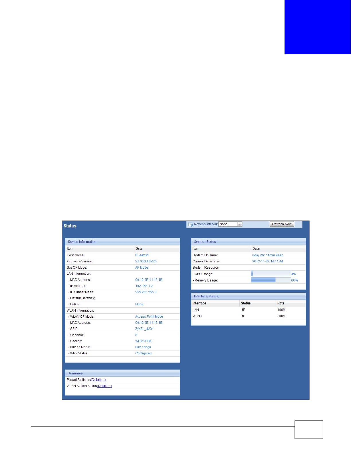
Use this screen to get a quick view of system, Ethernet, WLAN and other information regarding
your PLA4231.
Click Dashboard. The following screen displays.
CHAPTER 8
Dashboard
Figure 39 The Dashboard Screen
PLA4231 User’s Guide 55

Chapter 8 Dashboard
The following table describes the labels in this screen.
Table 13 The Dashboard Screen
LABEL DESCRIPTION
Refresh Interval Select a number of seconds or None from the drop-down list box to refresh all screen
statistics automatically at the end of every time interval or to not refresh the screen
statistics.
Refresh Now Click this button to refresh the status screen statistics.
Device Information
Host Name This is the PLA4231’s model name.
Firmware Version This is the firmware version and the date created.
Sys OP Mode This is the device mode to which the PLA4231 is set - AP Mode.
LAN Information
MAC Address This shows the LAN Ethernet adapter MAC Address of your device.
IP Address This shows the LAN port’s IP address.
IP Subnet Mask This shows the LAN port’s subnet mask.
Default Gateway This shows the gateway IP address.
DHCP This shows the LAN port’s DHCP role - Client or None.
WLAN Information
WLAN OP Mode This is the device mode to which the PLA4231’s wireless LAN is set - Access Point Mode.
MAC Address This shows the wireless adapter MAC Address of your device.
SSID This shows a descriptive name used to identify the PLA4231 in the wireless LAN.
Channel This shows the channel number which the PLA4231 is currently using over the wireless LAN.
Security This shows the level of wireless security the PLA4231 is using.
802.11 Mode This shows the wireless standard.
WPS Status This displays Configured when the WPS has been set up.
This displays Unconfigured if the WPS has not been set up.
Summary
Packet Statistics Click Details... to go to the Monitor > Packet Statistics screen (Section 9.4 on page 80).
Use this screen to view port status and packet specific statistics.
WLAN Station Status Click Details... to go to the Monitor > WLAN Station Status screen (Section 9.5 on page
System Status
Item This column shows the type of data the PLA4231 is recording.
Data This column shows the actual data recorded by the PLA4231.
System Up Time This is the total time the PLA4231 has been on.
Current Date/Time This field displays your PLA4231’s present date and time.
System Resource
CPU Usage This displays what percentage of the PLA4231’s processing ability is currently used. When
Memory Usage This shows what percentage of the heap memory the PLA4231 is using.
Interface Status
Interface This displays the PLA4231 port types. The port types are: LAN and WLAN.
81). Use this screen to view the wireless stations that are currently associated to the
PLA4231.
this percentage is close to 100%, the PLA4231 is running at full load, and the throughput is
not going to improve anymore. If you want some applications to have more throughput, you
should turn off other applications (for example, using bandwidth management.
56
PLA4231 User’s Guide

Chapter 8 Dashboard
Table 13 The Dashboard Screen
LABEL DESCRIPTION
Status For the LAN ports, this field displays Down (line is down) or Up (line is up or connected).
For the WLAN, it displays Up when the WLAN is enabled or Down when the WLAN is
disabled.
Rate For the LAN ports, this displays the port speed or N/A when the line is disconnected.
For the WLAN, it displays the maximum transmission rate when the WLAN is enabled and N/
A when the WLAN is disabled.
PLA4231 User’s Guide
57

Chapter 8 Dashboard
58
PLA4231 User’s Guide

9.1 Overview
This chapter discusses read-only information related to the device state of the PLA4231.
Note: To access the Monitor screens, you can also click the links in the Summary table of
the Status screen to view the packets sent/received as well as the status of clients
connected to the PLA4231.
9.2 What You Can Do
•Use the Log screen (Section 9.3 on page 59) to view the logs for the categories such as system
maintenance, system errors, and so on.
•use the Packet Statistics screen (Section 9.4 on page 60) to view port status, packet specific
statistics, the "system up time" and so on.
•Use the WLAN Station Status screen (Section 9.5 on page 61) to view the wireless stations
that are currently associated to the PLA4231.
CHAPTER 9
Monitor
9.3 Log
Use the View Log screen to see the logged messages for the PLA4231.
Log entries in red indicate system error logs. The log wraps around and deletes the old entries after
it fills.
Click Monitor > Log.
Figure 40 Monitor > View Log
PLA4231 User’s Guide 59

Chapter 9 Monitor
The following table describes the labels in this screen.
Table 14 Monitor > Log
LABEL DESCRIPTION
Display Select what logs you want to see from the Display drop list. The log choices depend on
Refresh Click Refresh to renew the log screen.
Clear Click Clear to delete all the logs.
# This field is a sequential value and is not associated with a specific entry.
Time This field displays the time the log was recorded.
Message This field states the reason for the log.
You can configure which logs to display in the View Log screen. Go to the Log Setting screen and
select the logs you wish to display. Click Apply to save your settings. Click Cancel to start the
screen afresh.
Figure 41 Monitor > Log Setting
your settings in the Log Setting screen.
9.4 Packet Statistics
Click the Packet Statistics (Details...) hyperlink in the Dashboard screen or Monitor > Packet
Statistics. Read-only information here includes port status, packet specific statistics and the
"system up time". The Poll Interval(s) field is configurable and is used for refreshing the screen.
Figure 42 Monitor > Packet Statistics
60
PLA4231 User’s Guide

Chapter 9 Monitor
The following table describes the labels in this screen.
Table 15 Monitor > Packet Statistics
LABEL DESCRIPTION
Port This is the PLA4231’s interface type.
Status For the LAN port, this displays the port speed or Down when the line is disconnected.
For the WLAN, it displays the maximum transmission rate when the WLAN is enabled
and Down when the WLAN is disabled.
TxPkts This is the number of transmitted packets on this port.
RxPkts This is the number of received packets on this port.
Collisions This is the number of collisions on this port.
Tx B/s This displays the transmission speed in bytes per second on this port.
Rx B/s This displays the reception speed in bytes per second on this port.
Up Time This is the total time the PLA4231 has been for each session.
System Up Time This is the total time the PLA4231 has been on.
Poll Interval(s) Enter the time interval in seconds for refreshing statistics in this field.
Set Interval Click this button to apply the new poll interval you entered in the Poll Interval(s)
Stop Click Stop to stop refreshing statistics.
field.
9.5 WLAN Station Status
Click the WLAN Station Status (Details...) hyperlink in the Dashboard screen or Monitor >
WLAN Station Status. View the wireless stations that are currently associated to the PLA4231 in
the Association List. Association means that a wireless client (for example, your network or
computer with a wireless network card) has connected successfully to the AP (or wireless router)
using the same SSID, channel and security settings.
Figure 43 Monitor > WLAN Station Status
The following table describes the labels in this screen.
Table 16 Monitor > WLAN Station Status
LABEL DESCRIPTION
# This is the index number of an associated wireless station.
MAC Address This field displays the MAC address of an associated wireless station.
Association Time This field displays the time a wireless station first associated with the PLA4231’s WLAN
network.
PLA4231 User’s Guide
61

Chapter 9 Monitor
62
PLA4231 User’s Guide

10.1 Overview
A
B
AP
This chapter discusses how to configure the wireless network settings in your PLA4231. See the
appendices for more detailed information about wireless networks.
The following figure provides an example of a wireless network.
Figure 44 Example of a Wireless Network
CHAPTER 10
Wireless LAN
The wireless network is the part in the blue circle. In this wireless network, devices A and B are
called wireless clients. The wireless clients use the access point (AP) to interact with other devices
(such as the printer) or with the Internet. Your PLA4231 is the AP.
10.2 What You Can Do
•Use the General screen (Section 10.4 on page 66) to turn the wireless connection on or off,
enter the SSID, select the channel, and configure wireless security between the PLA4231 and the
wireless clients.
•Use the MAC Filter screen (Section 10.6 on page 71) to allow or deny wireless stations based on
their MAC addresses from connecting to the PLA4231.
PLA4231 User’s Guide 63

Chapter 10 Wireless LAN
•Use the Advanced screen (Section 10.7 on page 73) to configure wireless advanced features,
such as set the RTS/CTS Threshold and HT physical mode.
•Use the QoS screen (Section 10.8 on page 73) to enable Wifi MultiMedia Quality of Service
(WMMQoS). This allows the PLA4231 to automatically set priority levels to services, such as email, VoIP, chat, and so on.
•Use the WPS screen (Section 10.9 on page 74) to quickly set up a wireless network with strong
security, without having to configure security settings manually.
•Use the WPS Station screen (Section 10.10 on page 76) to add a wireless station using WPS.
•Use the Scheduling screen (Section 10.11 on page 76) to set the times your wireless LAN is
turned on and off.
10.3 What You Should Know
Every wireless network must follow these basic guidelines.
• Every wireless client in the same wireless network must use the same SSID.
The SSID is the name of the wireless network. It stands for Service Set IDentity.
• If two wireless networks overlap, they should use different channels.
Like radio stations or television channels, each wireless network uses a specific channel, or
frequency, to send and receive information.
• Every wireless client in the same wireless network must use security compatible with the AP.
Security stops unauthorized devices from using the wireless network. It can also protect the
information that is sent in the wireless network.
10.3.1 Wireless Security Overview
The following sections introduce different types of wireless security you can set up in the wireless
network.
10.3.1.1 SSID
Normally, the AP acts like a beacon and regularly broadcasts the SSID in the area. You can hide the
SSID instead, in which case the AP does not broadcast the SSID. In addition, you should change
the default SSID to something that is difficult to guess.
This type of security is fairly weak, however, because there are ways for unauthorized devices to
get the SSID. In addition, unauthorized devices can still see the information that is sent in the
wireless network.
10.3.1.2 MAC Address Filter
Every wireless client has a unique identification number, called a MAC address.1 A MAC address is
usually written using twelve hexadecimal characters
00:A0:C5:00:00:02. To get the MAC address for each wireless client, see the appropriate User’s
Guide or other documentation.
1. Some wireless devices, such as scanners, can detect wireless networks but cannot use wireless networks. These kinds
of wireless devices might not have MAC addresses.
2. Hexadecimal characters are 0, 1, 2, 3, 4, 5, 6, 7, 8, 9, A, B, C, D, E, and F.
2
; for example, 00A0C5000002 or
64
PLA4231 User’s Guide

Chapter 10 Wireless LAN
You can use the MAC address filter to tell the AP which wireless clients are allowed or not allowed to
use the wireless network. If a wireless client is allowed to use the wireless network, it still has to
have the correct settings (SSID, channel, and security). If a wireless client is not allowed to use the
wireless network, it does not matter if it has the correct settings.
This type of security does not protect the information that is sent in the wireless network.
Furthermore, there are ways for unauthorized devices to get the MAC address of an authorized
wireless client. Then, they can use that MAC address to use the wireless network.
Encryption
Wireless networks can use encryption to protect the information that is sent in the wireless
network. Encryption is like a secret code. If you do not know the secret code, you cannot
understand the message.
Table 17 Types of Encryption
Weakest No Security
Static WEP
WPA-PSK
Strongest WPA2-PSK
Usually, you should set up the strongest encryption that every wireless client in the wireless
network supports. For example, suppose the AP does not have a local user database, and you do
not have a RADIUS server. Therefore, there is no user authentication. Suppose the wireless network
has two wireless clients. Device A only supports WEP, and device B supports WEP and WPA.
Therefore, you should set up Static WEP in the wireless network.
Note: It is recommended that wireless networks use WPA-PSK or stronger encryption.
When you select WPA2-PSK in your PLA4231, you can also select an option (WPA-PSK
Compatible) to support WPA as well. In this case, if some wireless clients support WPA and some
support WPA2, you should set up WPA2-PSK and select the WPA-PSK Compatible option in the
PLA4231.
Many types of encryption use a key to protect the information in the wireless network. The longer
the key, the stronger the encryption. Every wireless client in the wireless network must have the
same key.
10.3.1.3 WPS
WiFi Protected Setup (WPS) is an industry standard specification, defined by the WiFi Alliance. WPS
allows you to quickly set up a wireless network with strong security, without having to configure
security settings manually. Depending on the devices in your network, you can either press a
button (on the device itself, or in its configuration utility) or enter a PIN (Personal Identification
Number) in the devices. Then, they connect and set up a secure network by themselves.
WEP encryption are better than none at all, but it is still possible for unauthorized
devices to figure out the original information pretty quickly.
PLA4231 User’s Guide
65

Chapter 10 Wireless LAN
10.4 General Wireless LAN Screen
Use this screen to enable or disable the WLAN, enter the SSID, select the channel and configure
wireless security settings.
Note: If you are configuring the PLA4231 from a computer connected to the wireless LAN
and you change the PLA4231’s SSID, channel or security settings, you will lose
your wireless connection when you press Apply to confirm. You must then change
the wireless settings of your computer to match the PLA4231’s new settings.
Click Network > Wireless LAN to open the General screen.
Figure 45 Network > Wireless LAN > General
66
The following table describes the general wireless LAN labels in this screen.
Table 18 Network > Wireless LAN > General
LABEL DESCRIPTION
Wireless Setup
Wireless LAN Select to enable or disable the wireless LAN. This is turned on by default.
Name (SSID) The SSID (Service Set IDentity) identifies the Service Set with which a wireless client is
associated. Enter a descriptive name (up to 32 printable characters found on a typical
English language keyboard) for the wireless LAN.
Hide SSID Select this check box to hide the SSID in the outgoing beacon frame so a wireless client
cannot obtain the SSID through scanning using a site survey tool.
Channel
Selection
Auto Channel
Selection
Set the operating frequency/channel depending on your particular region.
Select a channel from the drop-down list box. The options vary depending on the
frequency band and the country you are in.
This option is only available if Auto Channel Selection is disabled.
Select the check box to have the PLA4231 automatically scan for and select a channel
which is not used by another device.
PLA4231 User’s Guide

Chapter 10 Wireless LAN
Table 18 Network > Wireless LAN > General
LABEL DESCRIPTION
Operating
Channel
Channel Width Select the wireless channel width used by PLA4231.
802.11 Mode You can select from the following:
Security Mode Select Static WEP, WPA-PSK, or WPA2-PSK to add security on this wireless network.
This displays the channel the PLA4231 is currently using.
A standard 20 MHz channel offers transfer speeds of up to 150Mbps whereas a 40 MHz
channel uses two standard channels and offers speeds of up to 300 Mbps.
Because not all devices support 40 MHz channels, select Auto 20/40 MHz to allow the
PLA4231 to adjust the channel bandwidth automatically.
40 MHz (channel bonding or dual channel) bonds two adjacent radio channels to increase
throughput. The wireless clients must also support 40 MHz. It is often better to use the 20
MHz setting in a location where the environment hinders the wireless signal.
Select 20 MHz if you want to lessen radio interference with other wireless devices in your
neighborhood or the wireless clients do not support channel bonding.
• 802.11b: allows either IEEE 802.11b or IEEE 802.11g compliant WLAN devices to
associate with the PLA4231. In this mode, all wireless devices can only transmit at the
data rates supported by IEEE 802.11b.
• 802.11g: allows IEEE 802.11g compliant WLAN devices to associate with the Device.
IEEE 802.11b compliant WLAN devices can associate with the PLA4231 only when they
use the short preamble type.
• 802.11bg: allows either IEEE 802.11b or IEEE 802.11g compliant WLAN devices to
associate with the PLA4231. The PLA4231 adjusts the transmission rate automatically
according to the wireless standard supported by the wireless devices.
• 802.11n: allows IEEE 802.11n compliant WLAN devices to associate with the
PLA4231. This can increase transmission rates, although IEEE 802.11b or IEEE
802.11g clients will not be able to connect to the PLA4231. I
• 802.11gn: allows either IEEE 802.11g or IEEE 802.11n compliant WLAN devices to
associate with the PLA4231. The transmission rate of your PLA4231 might be
reduced.
• 802.11 bgn: allows IEEE802.11b, IEEE802.11g and IEEE802.11n compliant WLAN
devices to associate with the PLA4231. The transmission rate of your PLA4231 might
be reduced.
The wireless clients which want to associate to this network must have same wireless
security settings as this device. After you select to use a security, additional options
appears in this screen. See Section 10.5 on page 67 for detailed information on different
security modes. Or you can select No Security to allow any client to associate this
network without authentication.
Note: If the WPS function is enabled (default), only No Security and WPA2-PSK are
available in this field.
Apply Click Apply to save your changes back to the PLA4231.
Cancel Click Cancel to reload the previous configuration for this screen.
10.5 Wireless Security
The screen varies depending on what you select in the Security Mode field.
10.5.1 No Security
Select No Security to allow wireless clients to communicate with the access points without any
data encryption.
PLA4231 User’s Guide
67

Chapter 10 Wireless LAN
Note: If you do not enable any wireless security on your PLA4231, your network is
accessible to any wireless networking device that is within range.
Figure 46 Network > Wireless LAN > Security: No Security
The following table describes the labels in this screen.
Table 19 Network > Wireless LAN > Security: No Security
LABEL DESCRIPTION
Security Mode Choose No Security from the drop-down list box.
Apply Click Apply to save your changes back to the PLA4231.
Cancel Click Cancel to reload the previous configuration for this screen.
10.5.2 WEP Encryption
WEP encryption scrambles the data transmitted between the wireless stations and the access points
to keep network communications private. It encrypts unicast and multicast communications in a
network. Both the wireless stations and the access points must use the same WEP key.
Your PLA4231 allows you to configure up to four 64-bit or 128-bit WEP keys but only one key can be
enabled at any one time.
Select Static WEP from the Security Mode list.
68
PLA4231 User’s Guide

Figure 47 Network > Wireless LAN > Security: Static WEP
Chapter 10 Wireless LAN
The following table describes the wireless LAN security labels in this screen.
Table 20 Network > Wireless LAN > Security: Static WEP
LABEL DESCRIPTION
Security Mode Select Static WEP to enable data encryption.
PassPhrase Enter a passphrase (up to 26 printable characters) and click Generate.
WEP Encryption Select 64-bits or 128-bits.
Authentication
Method
ASCII Select this option in order to enter ASCII characters as WEP key.
PLA4231 User’s Guide
A passphrase functions like a password. In WEP security mode, it is further converted by
the PLA4231 into a complicated string that is referred to as the “key”. This key is requested
from all devices wishing to connect to a wireless network.
This dictates the length of the security key that the network is going to use.
Select Auto or Shared Key from the drop-down list box.
This field specifies whether the wireless clients have to provide the WEP key to login to the
wireless client. Keep this setting at Auto unless you want to force a key verification before
communication between the wireless client and the PLA4231 occurs.
Select Shared Key to force the clients to provide the WEP key prior to communication.
69

Chapter 10 Wireless LAN
Table 20 Network > Wireless LAN > Security: Static WEP
LABEL DESCRIPTION
Hex Select this option in order to enter hexadecimal characters as a WEP key.
The preceding "0x", that identifies a hexadecimal key, is entered automatically.
Key 1 to Key 4 The WEP keys are used to encrypt data. Both the PLA4231 and the wireless stations must
Apply Click Apply to save your changes back to the PLA4231.
Cancel Click Cancel to reload the previous configuration for this screen.
use the same WEP key for data transmission.
If you chose 64-bit WEP, then enter any 5 ASCII characters or 10 hexadecimal characters
("0-9", "A-F").
If you chose 128-bit WEP, then enter 13 ASCII characters or 26 hexadecimal characters
("0-9", "A-F").
You must configure at least one key, only one key can be activated at any one time. The
default key is key 1.
10.5.3 WPA-PSK/WPA2-PSK
Select WPA-PSK or WPA2-PSK from the Security Mode list.
Figure 48 Network > Wireless LAN > Security: WPA2-PSK
70
PLA4231 User’s Guide

The following table describes the labels in this screen.
Table 21 Network > Wireless LAN > Security: WPA-PSK/WPA2-PSK
LABEL DESCRIPTION
Security Mode Select WPA-PSK or WPA2-PSK to enable data encryption.
WPA-PSK
Compatible
Pre-Shared Key WPA-PSK/WPA2-PSK uses a simple common password for authentication.
Group Key Update
Timer
Apply Click Apply to save your changes back to the PLA4231.
Cancel Click Cancel to reload the previous configuration for this screen.
10.6 MAC Filter
Chapter 10 Wireless LAN
This field appears when you choose WPA2-PSK as the Security Mode.
Check this field to allow wireless devices using WPA-PSK security mode to connect to
your PLA4231.
Type a pre-shared key from 8 to 63 case-sensitive keyboard characters.
The Group Key Update Timer is the rate at which the AP sends a new group key out to
all clients.
The default is 3600 seconds (60 minutes).
The MAC filter screen allows you to configure the PLA4231 to give exclusive access to devices
(Allow) or exclude devices from accessing the PLA4231 (Deny). Every Ethernet device has a unique
MAC (Media Access Control) address. The MAC address is assigned at the factory and consists of six
pairs of hexadecimal characters, for example, 00:A0:C5:00:00:02. You need to know the MAC
address of the devices to configure this screen.
To change your PLA4231’s MAC filter settings, click Network > Wireless LAN > MAC Filter. The
screen appears as shown.
PLA4231 User’s Guide
71

Chapter 10 Wireless LAN
Figure 49 Network > Wireless LAN > MAC Filter
The following table describes the labels in this menu.
Table 22 Network > Wireless LAN > MAC Filter
LABEL DESCRIPTION
MAC Address
Filter
Filter Action Define the filter action for the list of MAC addresses in the MAC Filter Summary table.
MAC Filter Summary
Set This is the index number of the MAC address.
MAC Address Enter the MAC address of the wireless station that are allowed or denied access to the
Apply Click Apply to save your changes back to the PLA4231.
Cancel Click Cancel to reload the previous configuration for this screen.
Select to turn on (Enable) or off (Disable) MAC address filtering.
Select Allow to permit access to the PLA4231, MAC addresses not listed will be denied
access to the PLA4231.
Select Deny to block access to the PLA4231, MAC addresses not listed will be allowed to
access the PLA4231.
PLA4231.
72
PLA4231 User’s Guide

10.7 Wireless LAN Advanced Screen
Use this screen to allow wireless advanced features, such as the output power, and RTS/CTS
Threshold.
Click Network > Wireless LAN > Advanced. The screen appears as shown.
Figure 50 Network > Wireless LAN > Advanced
The following table describes the labels in this screen.
Chapter 10 Wireless LAN
Table 23 Network > Wireless LAN > Advanced
LABEL DESCRIPTION
RTS/CTS
Threshold
Fragmentation
Threshold
Intra-BSS Traffic A Basic Service Set (BSS) exists when all communications between wireless clients or
Tx Power Set the output power of the PLA4231 in this field. If there is a high density of APs in an
Apply Click Apply to save your changes back to the PLA4231.
Cancel Click Cancel to reload the previous configuration for this screen.
Data with its frame size larger than this value will perform the RTS (Request To Send)/CTS
(Clear To Send) handshake.
Note: If you select 802.11n, 802.11gn or 802.11bgn in the Wireless LAN > General screen,
this field is not configurable and the PLA4231 automatically changes to use the
maximum value.
The threshold (number of bytes) for the fragmentation boundary for directed messages. It
is the maximum data fragment size that can be sent.
Note: If you select 802.11n, 802.11gn or 802.11bgn in the Wireless LAN > General screen,
this field is not configurable and the PLA4231 automatically changes to use the
maximum value.
between a wireless client and a wired network client go through one access point (AP).
Intra-BSS traffic is traffic between wireless clients in the BSS. When Intra-BSS traffic is
enabled, wireless clients can access the wired network and communicate with each other.
When Intra-BSS traffic is disabled, wireless clients can still access the wired network but
cannot communicate with each other.
area, decrease the output power of the PLA4231 to reduce interference with other APs.
Select one of the following 100%, 90%, 75%, 50%, 25% or 10%.
10.8 Quality of Service (QoS) Screen
The QoS screen allows you to automatically give a service (such as VoIP and video) a priority level.
PLA4231 User’s Guide
73

Chapter 10 Wireless LAN
Click Network > Wireless LAN > QoS. The following screen appears.
Figure 51 Network > Wireless LAN > QoS
The following table describes the labels in this screen.
Table 24 Network > Wireless LAN > QoS
LABEL DESCRIPTION
WMM QoS Select Enable to have the PLA4231 automatically give a service a priority level
Apply Click Apply to save your changes to the PLA4231.
Cancel Click Cancel to reload the previous configuration for this screen.
according to the ToS value in the IP header of packets it sends. WMM QoS (Wifi
MultiMedia Quality of Service) gives high priority to voice and video, which makes
them run more smoothly.
Note: If you select 802.11n, 802.11gn or 802.11bgn in the Wireless LAN > General
screen, this field is not configurable and the PLA4231 automatically enables
WMM QoS.
10.9 WPS Screen
Use this screen to enable/disable WPS, view or generate a new PIN number and check current WPS
status. To open this screen, click Network > Wireless LAN > WPS tab.
74
PLA4231 User’s Guide

Figure 52 Network > Wireless LAN > WPS
The following table describes the labels in this screen.
Chapter 10 Wireless LAN
Table 25 Network > Wireless LAN > WPS
LABEL DESCRIPTION
WPS Setup
WPS Select Enable to turn on the WPS feature. Otherwise, select Disable.
PIN Code Select Enable and click Apply to allow the PIN Configuration method. If you select
PIN Number This is the WPS PIN (Personal Identification Number) of the PLA4231. Enter this PIN in the
Status
Status This displays Configured when the PLA4231 has connected to a wireless network using
Release
Configuration
802.11 Mode This is the 802.11 mode used. Only compliant WLAN devices can associate with the
SSID This is the name of the wireless network (the PLA4231’s first SSID).
Security This is the type of wireless security employed by the network.
Apply Click Apply to save your changes back to the PLA4231.
Cancel Click Cancel to reload the previous configuration for this screen.
Disable, you cannot create a new PIN number.
configuration utility of the device you want to connect to the PLA4231 using WPS.
The PIN is not necessary when you use WPS push-button method.
Click Generate to generate a new PIN number.
WPS or when Enable WPS is selected and wireless or wireless security settings have
been changed. The current wireless and wireless security settings also appear in the
screen.
This displays Unconfigured if WPS is disabled and there are no wireless or wireless
security changes on the PLA4231 or you click Release_Configuration to remove the
configured wireless and wireless security settings.
This button is only available when the WPS status displays Configured.
Click this button to remove all configured wireless and wireless security settings for WPS
connections on the PLA4231.
PLA4231.
PLA4231 User’s Guide
75

Chapter 10 Wireless LAN
10.10 WPS Station Screen
Use this screen when you want to add a wireless station using WPS. To open this screen, click
Network > Wireless LAN > WPS Station tab.
Note: After you click Push Button on this screen, you have to press a similar button in
the wireless station utility within 2 minutes. To add the second wireless station, you
have to press these buttons on both device and the wireless station again after the
first 2 minutes.
Figure 53 Network > Wireless LAN > WPS Station
The following table describes the labels in this screen.
Table 26 Network > Wireless LAN > WPS Station
LABEL DESCRIPTION
Push Button Use this button when you use the PBC (Push Button Configuration) method to configure
wireless stations’s wireless settings.
Click this to start WPS-aware wireless station scanning and the wireless security
information synchronization.
Or input station’s
PIN number
Use this button when you use the PIN Configuration method to configure wireless station’s
wireless settings.
Type the same PIN number generated in the wireless station’s utility. Then click Start to
associate to each other and perform the wireless security information synchronization.
10.11 Scheduling Screen
Use this screen to set the times your wireless LAN is turned on and off. Wireless LAN scheduling is
disabled by default. The wireless LAN can be scheduled to turn on or off on certain days and at
certain times. To open this screen, click Network > Wireless LAN > Scheduling tab.
76
PLA4231 User’s Guide

Figure 54 Network > Wireless LAN > Scheduling
The following table describes the labels in this screen.
Chapter 10 Wireless LAN
Table 27 Network > Wireless LAN > Scheduling
LABEL DESCRIPTION
Wireless LAN
Scheduling
Scheduling
WLAN Status Select On or Off to specify whether the Wireless LAN is turned on or off. This field works
Day Select Everyday or the specific days to turn the Wireless LAN on or off. If you select
For the following
times (24-Hour
Format)
Apply Click Apply to save your changes back to the PLA4231.
Cancel Click Cancel to reload the previous configuration for this screen.
Select Enable to activate the wireless LAN scheduling feature. Select Disable to turn it
off.
in conjunction with the Day and For the following times fields.
Everyday you can not select any specific days. This field works in conjunction with the
For the following times field.
Select a begin time using the first set of hour and minute (min) drop down boxes and
select an end time using the second set of hour and minute (min) drop down boxes. If
you have chosen On earlier for the WLAN Status the Wireless LAN will turn on between
the two times you enter in these fields. If you have chosen Off earlier for the WLAN
Status the Wireless LAN will turn off between the two times you enter in these fields.
PLA4231 User’s Guide
77

Chapter 10 Wireless LAN
78
PLA4231 User’s Guide

11.1 Overview
LAN
This chapter describes how to configure LAN settings.
A Local Area Network (LAN) is a shared communication system to which many computers are
attached. A LAN is a computer network limited to the immediate area, usually the same building or
floor of a building. The LAN screens can help you configure the manage IP address, and partition
your physical network into logical networks.
Figure 55 LAN Example
CHAPTER 11
LAN
The LAN screens can help you manage IP addresses.
11.2 What You Can Do
•Use the IP screen (Section 11.4 on page 80) to change the IP address for your PLA4231 and DNS
server information.
•Use the IP Alias screen (Section 11.5 on page 81) to have the PLA4231 apply IP alias to create
LAN subnets.
11.3 What You Need To Know
There are two separate IP networks, one inside the LAN network and the other outside the WAN
network as shown next.
PLA4231 User’s Guide 79

Chapter 11 LAN
LAN
WAN
Figure 56 LAN and WAN IP Addresses
The LAN parameters of the PLA4231 are preset in the factory with the following values:
• IP address of 192.168.1.2 with subnet mask of 255.255.255.0 (24 bits)
11.3.1 LAN TCP/IP
The PLA4231 has built-in DHCP server capability that assigns IP addresses and DNS servers to
systems that support DHCP client capability.
11.3.2 IP Alias
IP alias allows you to partition a physical network into different logical networks over the same
Ethernet interface. The PLA4231 supports three logical LAN interfaces via its single physical
Ethernet interface with the PLA4231 itself as the gateway for each LAN network.
11.4 LAN IP Screen
Use this screen to change the IP address for your PLA4231. Click Network > LAN > IP.
Figure 57 Network > LAN > IP (Access Point or Universal Repeater)
80
PLA4231 User’s Guide

Chapter 11 LAN
The following table describes the labels in this screen.
Table 28 Network > LAN > IP
LABEL DESCRIPTION
Obtain an IP
Address
Automatically
Static IP Address Click this if you want to specify the IP address of your PLA4231. Or if your ISP or
IP Address Type the IP address in dotted decimal notation. The default setting is 192.168.1.2. If
Subnet Mask The subnet mask specifies the network number portion of an IP address.
Gateway IP
Address
DNS Server
First DNS Server
Second DNS Server
Apply Click Apply to save your changes back to the PLA4231.
Cancel Click Cancel to reload the previous configuration for this screen.
Click this to deploy the PLA4231 as a DHCP client in the network.
When you enable this, the PLA4231 gets its IP address from the network’s DHCP server
(for example, your ISP or router). Users connected to the PLA4231 can now access the
network (i.e., the Internet if the IP address is given by the ISP or a router with Internet
access).
The Web Configurator may no longer be accessible unless you know the IP address
assigned by the DHCP server to the PLA4231. Otherwise, you need to reset the PLA4231
to be able to access the Web Configurator again (see Section 13.7 on page 92 for details
on how to reset the PLA4231).
Also when you select this, you cannot enter an IP address for your PLA4231 in the field
below.
network administrator gave you a static IP address to access the network or the
Internet.
you change the IP address you will have to log in again with the new IP address.
Enter a gateway IP address (if your ISP or network administrator gave you one) in this
field.
Select Obtained From ISP if your ISP or router to which the PLA4231 connects
dynamically assigns DNS server information (and the PLA4231's WAN IP address). The
field to the right displays the (read-only) DNS server IP address that the ISP assigns.
Select User-Defined if you have the IP address of a DNS server. Enter the DNS server's
IP address in the field to the right.
Select None if you do not want to configure DNS servers. If you do not configure a DNS
server, you must know the IP address of a computer in order to access it.
11.5 IP Alias Screen
Use this screen to have the PLA4231 apply IP alias to create LAN subnets. Click LAN > IP Alias.
Figure 58 Network > LAN > IP Alias
PLA4231 User’s Guide
81

Chapter 11 LAN
The following table describes the labels in this screen.
Table 29 Network > LAN > IP Alias
LABEL DESCRIPTION
IP Alias Check this to enable IP alias.
IP Address Type the IP alias address of your PLA4231 in dotted decimal notation.
IP Subnet Mask The subnet mask specifies the network number portion of an IP address.
Apply Click Apply to save your changes back to the PLA4231.
Cancel Click Cancel to reload the previous configuration for this screen.
82
PLA4231 User’s Guide

12.1 Overview
This chapter describes how to configure powerline settings. See Chapter 5 on page 27 for more
information about powerline network security.
12.2 What You Can Do
Use the HomePlug screen (Section 12.3 on page 83) to secure, manage and set up Quality of
Service (QoS) on your powerline network.
CHAPTER 12
HomePlug
12.3 HomePlug Screen
Use this screen to change the powerline settings for your PLA4231. Click Network > HomePlug.
Figure 59 Network > HomePlug
PLA4231 User’s Guide 83

Chapter 12 HomePlug
The following table describes the labels in this screen.
Table 30 Configuration Screen
LABEL DESCRIPTION
Network
Refresh Interval Select a number of seconds or None from the drop-down list box to update the powerline
The fields described below are used to identify the powerline adapters recognized on the powerline network.
Click Scan to refresh the information in these fields (immediately).
Note: Only devices which share the same network name are displayed in this table.
Site This field displays
MAC Address This is a read-only field which shows the MAC address of the powerline adapter you are
DAK Password DAK (Device Access Key) password is used to verify that you are authorized to perform
network information automatically at the end of every time interval or to not refresh the
powerline network information.
• Local, if it is identifying the powerline adapter directly connected to the computer
running the Web Configurator.
• Remote, if it is a powerline adapter in your powerline network but not directly
connected to the computer running the Web Configurator.
configuring. You can find the MAC address of your PLA4231 displayed on a sticker on the
bottom of your device.
changes on a remote device. You can find the DAK password printed on a sticker on the
bottom of your PLA4231.
Select the remote powerline adapter you want to manage by clicking the MAC address
which corresponds to it in the MAC Address column. Enter the DAK Password value and
click Save.
Note: You must enter the DAK Password value exactly as it is printed on the label (all caps
and with dashes “-”).
Network Name
(NMK)
Set NMK to this
device
Set NMK to all
devices
Write Click this to apply your changes. The new Network Name is applied to the selected
The default network name (sometimes called a network password or network membership
key (NMK)) of the PLA4231 is “HomePlugAV”. HomePlug compatible devices use the same
network name to recognize and communicate with each other over the powerline network.
If you change the network name of one device on the network, it will no longer be
recognized as part of that network.
If you change the network name, make sure you change the network name for all of the
powerline adapters that you want to be part of your powerline network.
The network name can be from 8 to 64 characters in length, using “A”~”Z”, “a”~”z”,
“0”~”9”; spaces are not allowed.
Select this to apply the NMK (entered in the field above) as the network name for the
powerline adapter directly connected to the computer running the Web Configurator.
Select this to apply the NMK (entered in the field above) as the network name for all
powerline adapter detected by the Web Configurator.
powerline adapter.
Note: You must enter the correct DAK password for the selected powerline adapter before
you can make changes to it.
Network
Information
84
PLA4231 User’s Guide

Chapter 12 HomePlug
Table 30 Configuration Screen (continued)
LABEL DESCRIPTION
Central
Coordinator
MAC
The information provided in the following table reflects transmission rate information about the powerline
adapters which communicate in your powerline network.
The powerline adapters listed in this table are all the powerline adapters in your powerline network except the
powerline adapter selected in the table of the Network Name section. In other words, if the Local powerline
adapter is selected in the table of the Network Name section, then this table will display the rates of
transmission from the powerline adapter connected to the computer running the Web Configurator to all the
Remote powerline adapters.
Site This field displays:
MAC Address This field displays the MAC address of your powerline adapter. The MAC address of your
Tra nsmi t Ra te
(Mbps)
Receive Rate
(Mbps)
The Central Coordinator of the powerline network is the powerline adapter which keeps
track of which devices are part of the network as well as synchronizes communication
within the powerline network. If the Central Coordinator is removed from the powerline
network then another powerline adapter takes its place. This field displays the MAC address
of the PLA4231 which is the Central Coordinator of the powerline network. The powerline
adapters in your powerline network automatically select the Central Coordinator.
• Local, if it is the PLA4231 directly connected to the computer running the Web
Configurator.
• Remote, if it is a PLA4231 in your powerline network but not directly connected to the
computer running the Web Configurator.
powerline adapter can be found by looking at the label on your device. It consists of six
pairs of hexadecimal characters (hexadecimal characters are “0-9” and “a-f”). In the case
of the PLA4231, this label is on the bottom of the device.
This field displays how fast information is sent from the powerline adapter selected in the
table of the Network Name section to this powerline adapter. The rate is given in the
following format: “application data transmission rate / raw data transmission rate”.
Application data reflects more accurately how fast devices are transmitting application
relevant traffic (for example Internet Protocol (IP) traffic). Raw data refers to the whole
payload of the packets transmitted across the powerline network.
This field displays how fast information is received from the powerline adapter selected in
the table of the Network Name section to this powerline adapter. The rate is given in the
following format: “application data transmission rate / raw data transmission rate”.
Application data reflects more accurately how fast devices are transmitting application
relevant traffic (for example Internet Protocol (IP) traffic). Raw data refers to the whole
payload of the packets transmitted across the powerline network.
PLA4231 User’s Guide
85

Chapter 12 HomePlug
86
PLA4231 User’s Guide

13.1 Overview
This chapter provides information on the Maintenance screens.
13.2 What You Can Do
•Use the General screen (Section 13.3 on page 87) to set the timeout period of the management
session.
•Use the Password screen (Section 13.4 on page 88) to change your PLA4231’s system
password.
•Use the Time screen (Section 13.5 on page 88) to change your PLA4231’s time and date.
•Use the Firmware Upgrade screen (Section 13.6 on page 90) to upload firmware to your
PLA4231.
•Use the Backup/Restore screen (Section 13.8 on page 93) to view information related to
factory defaults, backup configuration, and restoring configuration.
•Use the Restart screen (Section 13.8 on page 93) to reboot the PLA4231 without turning the
power off.
•Use the Language screen (Section 13.9 on page 93) to change the language for the Web
Configurator.
CHAPTER 13
Maintenance
13.3 General Screen
Use this screen to set the management session timeout period. Click Maintenance > General.
The following screen displays.
Figure 60 Maintenance > General
PLA4231 User’s Guide 87

Chapter 13 Maintenance
The following table describes the labels in this screen.
Table 31 Maintenance > General
LABEL DESCRIPTION
Administrator
Inactivity Timer
Apply Click Apply to save your changes back to the PLA4231.
Cancel Click Cancel to reload the previous configuration for this screen.
Type how many minutes a management session can be left idle before the session times
out. The default is 5 minutes. After it times out you have to log in with your password
again. Very long idle timeouts may have security risks. A value of "0" means a
management session never times out, no matter how long it has been left idle (not
recommended).
13.4 Password Screen
It is strongly recommended that you change your PLA4231's password.
If you forget your PLA4231's password (or IP address), you will need to reset the device. See
Section 13.8 on page 93 for details
Click Maintenance > Password.
Figure 61 Maintenance > Password
The following table describes the labels in this screen.
Table 32 Maintenance > Password
LABEL DESCRIPTION
Old Password Type the default password or the existing password you use to access the system in
this field.
New Password Type your new system password (up to 30 characters). Note that as you type a
password, the screen displays an asterisk (*) for each character you type.
Retype to Confirm Type the new password again in this field.
Apply Click Apply to save your changes back to the PLA4231.
Cancel Click Cancel to reload the previous configuration for this screen.
13.5 Time Setting Screen
Use this screen to configure the PLA4231’s time based on your local time zone. To change your
PLA4231’s time and date, click Maintenance > Time. The screen appears as shown.
88
PLA4231 User’s Guide

Figure 62 Maintenance > Time
Chapter 13 Maintenance
he following table describes the labels in this screen.
Table 33 Maintenance > Time
LABEL DESCRIPTION
Current Time and Date
Current Time This field displays the time of your PLA4231.
Each time you reload this page, the PLA4231 synchronizes the time with the time
server.
Current Date This field displays the date of your PLA4231.
Each time you reload this page, the PLA4231 synchronizes the date with the time
server.
Time and Date Setup
Manual Select this radio button to enter the time and date manually. If you configure a new
New Time
(hh:mm:ss)
New Date
(yyyy/mm/dd)
Get from Time
Server
User Defined Time
Server Address
time and date, Time Zone and Daylight Saving at the same time, the new time and date
you entered has priority and the Time Zone and Daylight Saving settings do not affect
it.
This field displays the last updated time from the time server or the last time
configured manually.
When you select Manual, enter the new time in this field and then click Apply.
This field displays the last updated date from the time server or the last date configured
manually.
When you select Manual, enter the new date in this field and then click Apply.
Select this radio button to have the PLA4231 get the time and date from the time
server you specified below.
Enter the IP address or URL (up to 20 extended ASCII characters in length) of your
time server. Check with your ISP/network administrator if you are unsure of this
information.
PLA4231 User’s Guide
89

Chapter 13 Maintenance
Table 33 Maintenance > Time
LABEL DESCRIPTION
Time Zone Setup
Time Zone Choose the time zone of your location. This will set the time difference between your
Daylight Savings Daylight saving is a period from late spring to fall when many countries set their clocks
Start Date Configure the day and time when Daylight Saving Time starts if you selected Daylight
End Date Configure the day and time when Daylight Saving Time ends if you selected Daylight
Apply Click Apply to save your changes back to the PLA4231.
Cancel Click Cancel to reload the previous configuration for this screen.
time zone and Greenwich Mean Time (GMT).
ahead of normal local time by one hour to give more daytime light in the evening.
Select this option if you use Daylight Saving Time.
Savings. The o'clock field uses the 24 hour format. Here are a couple of examples:
Daylight Saving Time starts in most parts of the United States on the second Sunday of
March. Each time zone in the United States starts using Daylight Saving Time at 2 A.M.
local time. So in the United States you would select Second, Sunday, March and type
2 in the o'clock field.
Daylight Saving Time starts in the European Union on the last Sunday of March. All of
the time zones in the European Union start using Daylight Saving Time at the same
moment (1 A.M. GMT or UTC). So in the European Union you would select Last,
Sunday, March. The time you type in the o'clock field depends on your time zone. In
Germany for instance, you would type 2 because Germany's time zone is one hour
ahead of GMT or UTC (GMT+1).
Savings. The o'clock field uses the 24 hour format. Here are a couple of examples:
Daylight Saving Time ends in the United States on the first Sunday of November. Each
time zone in the United States stops using Daylight Saving Time at 2 A.M. local time.
So in the United States you would select First, Sunday, November and type 2 in the
o'clock field.
Daylight Saving Time ends in the European Union on the last Sunday of October. All of
the time zones in the European Union stop using Daylight Saving Time at the same
moment (1 A.M. GMT or UTC). So in the European Union you would select Last,
Sunday, October. The time you type in the o'clock field depends on your time zone.
In Germany for instance, you would type 2 because Germany's time zone is one hour
ahead of GMT or UTC (GMT+1).
13.6 Firmware Upgrade Screen
Find firmware at www.zyxel.com in a file that (usually) uses the system model name with a “*.bin”
extension, e.g., “PLA4231.bin”. The upload process uses HTTP (Hypertext Transfer Protocol) and
may take up to two minutes. After a successful upload, the system will reboot.
Click Maintenance > Firmware Upgrade. Follow the instructions in this screen to upload
firmware to your PLA4231.
90
PLA4231 User’s Guide

Chapter 13 Maintenance
Figure 63 Maintenance > Firmware Upgrade
The following table describes the labels in this screen.
Table 34 Maintenance > Firmware Upgrade
LABEL DESCRIPTION
Firmware Upgrade
File Path Type in the location of the file you want to upload in this field or click Browse... to find it.
Browse... Click Browse... to find the .bin file you want to upload. Remember that you must
Upload Click Upload to begin the upload process. This process may take up to two minutes.
On-line Firmware Upgrade
Check for Latest
Firmware Now
DoFirmware_Upgra
de
decompress compressed (.zip) files before you can upload them.
Click this button to get the latest firmware information, such as the version number, release
date, release note and file size from the ZyXEL website. Make sure your PLA4231 has
Internet access.
Click this button to download and install the latest firmware in your PLA4231.
Note: Do not turn off the PLA4231 while firmware upload is in progress!
After you click Upload, wait two minutes before logging into the PLA4231 again.
The PLA4231 automatically restarts in this time causing a temporary network disconnect. In some
operating systems, you may see the following icon on your desktop.
Figure 64 Network Temporarily Disconnected
After two minutes, log in again and check your new firmware version in the Dashboard screen.
PLA4231 User’s Guide
91
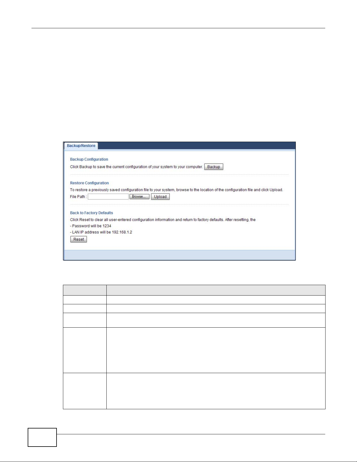
Chapter 13 Maintenance
13.7 Configuration Backup/Restore Screen
Backup configuration allows you to back up (save) the PLA4231’s current configuration to a file on
your computer. Once your PLA4231 is configured and functioning properly, it is highly
recommended that you back up your configuration file before making configuration changes. The
backup configuration file will be useful in case you need to return to your previous settings.
Restore configuration allows you to upload a new or previously saved configuration file from your
computer to your PLA4231.
Click Maintenance > Backup/Restore. Information related to factory defaults, backup
configuration, and restoring configuration appears as shown next.
Figure 65 Maintenance > Backup/Restore
92
The following table describes the labels in this screen.
Table 35 Maintenance > Backup/Restore
LABEL DESCRIPTION
Backup Click Backup to save the PLA4231’s current configuration to your computer.
File Path Type in the location of the file you want to upload in this field or click Browse... to find it.
Browse... Click Browse... to find the file you want to upload. Remember that you must decompress
compressed (.ZIP) files before you can upload them.
Upload Click Upload to begin the upload process.
Note: Do not turn off the PLA4231 while configuration file upload is in progress.
After you click Upload, you must then wait one minute before logging into the PLA4231
again. The PLA4231 automatically restarts in this time causing a temporary network
disconnect.
Reset Pressing the Reset button in this section clears all user-entered configuration information
and returns the PLA4231 to its factory defaults.
You can also press the RESET button on the rear panel to reset the factory defaults of your
PLA4231. Refer to the chapter about introducing the Web Configurator for more information
on the RESET button.
PLA4231 User’s Guide

Note: If you uploaded the default configuration file you may need to change the IP
address of your computer to be in the same subnet as that of the default PLA4231
IP address (192.168.1.2).
13.8 Restart Screen
System restart allows you to reboot the PLA4231 without turning the power off.
Click Maintenance > Restart to open the following screen.
Figure 66 Maintenance > Restart
Click Restart to have the PLA4231 reboot. This does not affect the PLA4231's configuration.
Chapter 13 Maintenance
13.9 Language Screen
Use this screen to change the language for the Web Configurator.
Select the language you prefer and click Apply. The Web Configurator language changes after a
while without restarting the PLA4231.
Figure 67 Maintenance > Language
PLA4231 User’s Guide
93

Chapter 13 Maintenance
94
PLA4231 User’s Guide
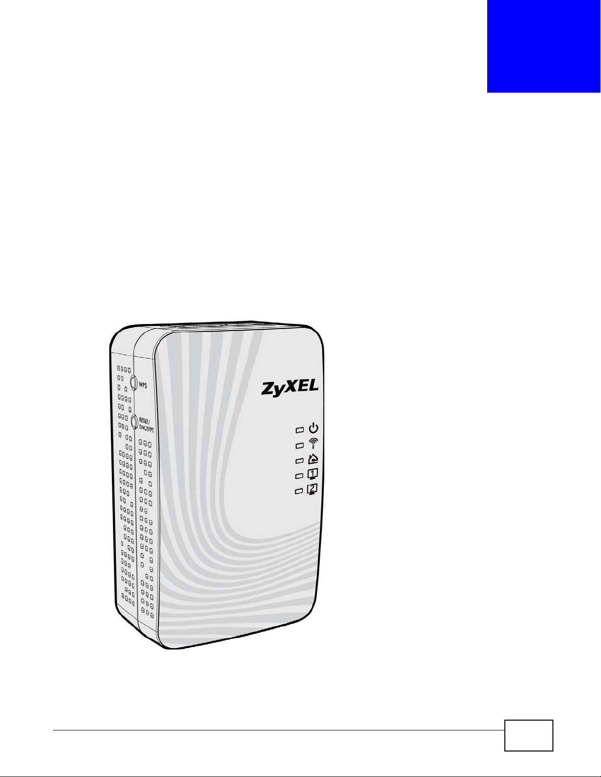
This chapter describes the behavior of the LEDs (lights) and offers some suggestions to solve
problems you might encounter.
14.1 LEDs
The following sections describes the lights on the PLA4231.
The following figure is the front panel of the PLA4231. Use the lights to determine if the PLA4231 is
behaving normally or if there are some problems on your powerline network.
Figure 68 PLA4231 Lights
CHAPTER 14
LEDs and Troubleshooting
PLA4231 User’s Guide 95

Chapter 14 LEDs and Troubleshooting
The following table describes the behavior of the lights on the PLA4231.
Table 36 PLA4231
LIGHTS ICON COLOR STATUS DESCRIPTION
POWER Green On The PLA4231 is on and receiving power.
WLAN Green On The PLA4231’s wireless LAN is ready, or WPS is enabled.
HomePlug Green On The PLA4231 detects another powerline adapter. The
Ethernet 1/
2
It also indicates a successful connection using the
RESET/ENCRYPT button.
Blinking The PLA4231 is starting up.
It also indicates the PLA4231 is trying to connect with
another device using the ENCRYPT function.
Blinking at the same time as the HomePlug light
indicates an unsuccessful connection if you have used
the RESET/ENCRYPT button.
Off The PLA4231 is not receiving power.
Fast
Blinking
Slow
Blinking
Off The wireless LAN is not ready or has failed.
Amber The PLA4231 detects another powerline adapter. The
Red The PLA4231 detects another powerline adapter. The
Green/
Amber/
Red
Green On The PLA4231 has a successful 10/100MB Ethernet
Blinking The PLA4231 is communicating with another powerline
Off The HomePlug port does not detect another powerline
Blinking The PLA4231 is communicating with a networking device
Off The PLA4231 does not detect any devices connected to
The PLA4231 is sending/receiving data through the
wireless LAN, or WPS has failed.
The PLA4231 is negotiating a WPS connection with a
wireless device.
data transfer rate is greater than 80 Mbps.
data transfer rate is between 20~80 Mbps.
data transfer rate is between 0~20 Mbps.
adapter. Data is being transmitted and/or received.
Blinking at the same time as the POWER light indicates
an unsuccessful connection if you have used the
RESET/ENCRYPT button.
adapter.
connection.
connected to the Ethernet port.
its Ethernet port.
14.2 Power and Light Problems
The PLA4231 does not turn on. None of the lights turn on.
1 Make sure the PLA4231 is plugged in to an appropriate power source.
96
PLA4231 User’s Guide

Chapter 14 LEDs and Troubleshooting
2 Make sure the power button at the side of the PLA4231 is pushed in.
3 Remove the powerline adapter from the outlet. Then connect an electrical device that you know
works into the same power outlet. This checks the status of the power outlet.
4 If the problem continues, contact the vendor.
The Ethernet light does not turn on.
1 Check the hardware connections. See the Quick Start Guide.
2 Inspect your cables for damage. Contact the vendor to replace any damaged cables.
3 Check the Ethernet adapter on your computer and make sure it’s enabled and working properly.
4 If the PLA4231 is connected to an Ethernet switch or router, make sure the device is working
correctly, and that the LAN network is working and configured correctly as well.
The HomePlug light does not turn on.
1 Check all PLA4231s on your network have the latest firmware installed. PLA4231s with the latest
firmware cannot communicate with PLA4231s using earlier versions of the firmware. Go to Section
5.4 on page 30 or Section 13.6 on page 90 for instructions on installing the latest firmware.
2 Use the PLA42xx Series Configuration Utility to detect all other HomePlug devices on your
powerline network. Make sure that the network name (sometimes called the network password) is
the same on all of your powerline adapters. See Section 5.3 on page 29 or Section 12.3 on page 83
for instructions on checking the network name.
3 Check the DAK password and MAC address for all powerline adapters are typed correctly in the
utility. See Section 5.3 on page 29 or Section 12.3 on page 83 for instructions on checking the DAK
and MAC address.
4 Make sure that all your powerline adapters are HomePlug AV compliant. Check the package it came
in or ask your vendor. This PLA4231 can not detect earlier versions of HomePlug powerline adapters
such as HomePlug 1.0 or 1.0.1. (Although they can coexist on the same electrical wiring without
interfering with each other.)
5 Make sure that the powerline adapters on your network are all on the same electrical wiring.
Connect another powerline adapter into an outlet close to your PLA4231’s power outlet. They are
probably now on the same electrical wiring. Check the HomePlug light. If it now lights up your
powerline adapter was probably previously on separate electrical wiring. Ask an electrician for more
information on the electrical wiring in your building.
6 If your powerline network is using coaxial cable, check all powerline adapters are on the same
coaxial cable.
PLA4231 User’s Guide
97

Chapter 14 LEDs and Troubleshooting
7 If your powerline network is using electrical wiring (not coaxial cable), check you do not have a
power meter between powerline adapters. Powerline signals cannot pass this.
The POWER and HomePlug light blink at the same time.
• You have pressed the RESET/ENCRYPT button for more than three seconds. Try setting up a
connection again, this time pressing the RESET/ENCRYPT buttons on both devices for less than
three seconds.
14.3 Configuration Utility Problems
The PLA42xx Series Configuration Utility displays an error during installation.
• Make sure your computer is using Windows XP or Windows Vista (32-bit) operating system. At
the time of writing, this is the only compatible operating system for the configuration utility.
The PLA42xx Series Configuration Utility does not display all or any of my devices.
• Inspect the LEDs on your PLA4231 and make sure that the ETHERNET and HomePlug LEDs are
on or blinking. See Section 14.1 on page 95 for troubleshooting LED related problems.
• Check all ZyxEL HomePlug AV devices on your network have the latest firmware installed. The
latest utility cannot communicate with PLA4231s using earlier versions of the firmware. Go to
Section 5.4 on page 30 or Section 13.6 on page 90 for instructions on installing the latest
firmware.
• Check you are using the latest version utility. Earlier version utilities cannot communicate with
PLA4231s using the latest firmware. If you do not have the latest utility, download it from the
ZyXEL website.
• If the device is not a ZyXEL device, then the DAK and Network Name will be greyed out.
• If you are running another tool such as the Firmware Detection Tool, the Utility will not detect
your local device.
14.4 Powerline Problems
The signal on my powerline network is weak.
1 Your powerline adapters may be connected to electrical surge protectors. Connect them to standard
power outlets.
98
PLA4231 User’s Guide

Chapter 14 LEDs and Troubleshooting
2 Your powerline adapters may be located close to large appliances such as refrigerators or air-
conditioners that cause interference with the powerline signal. Move the adapters further away
from such appliances to reduce interference.
3 Your powerline adapters may be placed close to electrical devices such as electrical insect-killers
which produce radio waves. These may interfere with the powerline signals. Move the adapters
further away from such electrical devices.
4 Your wiring may be old and/or low quality or with a long wiring path.
14.5 RESET/ENCRYPT Button Problems
This section applies only to PLA4231s with the RESET/ENCRYPT button.
The HomePlug light is already on, but I haven’t pressed the RESET/ENCRYPT button yet.
Your device has already connected to another powerline device. Press the RESET/ENCRYPT
button for 5 to 8 seconds to release the connection.
The POWER light does not blink when I press the RESET/ENCRYPT button.
• Check the device is on.
• Press the RESET/ENCRYPT button again, making certain you have pressed the button for 0.5 to
3 seconds.
• The POWER light on some powerline devices do not blink as part of the ENCRYPT process. Check
your powerline device is a PLA4231.
• For PLA4231, you cannot use the RESET/ENCRYPT button when it is in Low Power mode.
Connect the PLA4231 to a computer/router then try again.
The POWER light blinks two times quickly then pauses, before repeating.
The ENCRYPT process has failed. Press the RESET/ENCRYPT button on both devices for 5 to 8
seconds, then try to reconnect.
The POWER lights on both devices blink when I press the RESET/ENCRYPT buttons, but the
HomePlug light does not turn on.
• Ensure you have pressed the RESET/ENCRYPT button on both devices.
• Wait for about a minute while the devices set up a connection.
PLA4231 User’s Guide
99

Chapter 14 LEDs and Troubleshooting
• If that does not work, try again with both devices connected to a power strip next to each other.
If they now connect, then the devices were not on the same electrical circuit before.
The POWER lights on both devices blink, then many lights blink and the HomePlug light blinks
red.
Do not worry, the connection process is proceeding normally.
The POWER lights on both devices finished blinking, but only one device’s HomePlug light is
on.
One device may have connected to a third powerline device. To check device A is connected to
device B and not another device, disconnect device B from its power source. Device A’s HomePlug
( ) light will turn off if the connection is with Device B. Press the RESET/ENCRYPT button on
both devices for 5 to 8 seconds, then try to reconnect, pressing the RESET/ENCRYPT button for
0.5 to 3 seconds on both devices.
I pressed the RESET/ENCRYPT button for 5 to 8 seconds, but the HomePlug light is still on.
The HomePlug light is on, indicating it is still connected to another powerline device. Try again,
pressing the RESET/ENCRYPT button for 5 to 8 seconds.
14.6 Wireless Connection Problems
I cannot access the PLA4231 or ping any computer from the WLAN.
1 Make sure the wireless LAN is enabled on the PLA4231.
2 Make sure the wireless adapter installed on your computer is working properly.
3 Make sure the wireless adapter installed on your computer is IEEE 802.11 compatible and supports
the same wireless standard as the PLA4231.
4 Make sure your computer (with a wireless adapter installed) is within the transmission range of the
PLA4231.
5 Check that both the PLA4231 and your computer (with a wireless adapter installed) are using the
same wireless and wireless security settings.
100
PLA4231 User’s Guide
 Loading...