

Page 1

Default Login Details
CLI Reference Guide
NXC Series
Wireless LAN Controller
IP Address https://192.168.1.1
User Name admin
Password 1234
Version 6.00 Edition 1, 1/2020
Copyright © 2019 Zyxel Communications Corporation
Page 2

IMPORTANT!
READ CAREFULLY BEFORE USE.
KEEP THIS GUIDE FOR FUTURE REFERENCE.
This is a Reference Guide for a series of products intended for people who want to configure the NXC
via Command Line Interface (CLI).
Note: Some commands or command options in this guide may not be available in your
product. See your product's User’s Guide for a list of supported features. Every effort has
been made to ensure that the information in this guide is accurate.
Note: The version number on the cover page refers to the latest firmware version supported
by the NXC. This guide applies to versions 4.20, 4.21, 4.22, 4.30, 5.00, 5.10, 5.20, 5.30, 5.40,
and 6.00 at the time of writing.
How To Use This Guide
1 Read Chapter 1 on page 14 for how to access and use the CLI (Command Line Interface).
2 Read Chapter 2 on page 28 to learn about the CLI user and privilege modes.
Do not use commands not documented in this guide.
Related Documentation
•Quick Start Guide
The Quick Start Guide shows how to connect the NXC and access the Web Configurator.
• User’s Guide
The User’s Guide explains how to use the Web Configurator to configure the NXC.
Note: It is recommended you use the Web Configurator to configure the NXC.
Icons Used in Figures
Figures in this guide may use the following generic icons. The NXC icon is not an exact representation of
your device.
NXC Router Switch Internet
Server Desktop Laptop AP
Page 3

Contents Overview
Contents Overview
Command Line Interface ................................ ....... ....... ....... ....... ....... ....... ....... ....... .............. .............. 14
User and Privilege Modes .................................................................................................................... 28
Object Reference ................................................................................................................................ 31
Status ......................................................................... ............................................................................. 33
Registration ...................................................................... .......................................... ............................ 37
Interfaces ................................................................................ ............................................................... 43
Route ................................................................................ ...................................................................... 62
AP Management .................................................................................................................................. 69
AP Group ............................................................................................................................................... 80
Wireless LAN Profiles .............................................................................................................................. 87
Rogue AP ............................................................................................................................................. 108
Bluetooth ............................................................................................................................................. 112
Wireless Frame Capture ..................................................................................................................... 115
Dynamic Channel Selection ............................................................................................................. 117
Auto-Healing ....................................................................................................................................... 118
Dynamic Guest ................................................................................................................................... 120
LEDs ...................................................................................................................................................... 123
Zones ......................................................................... ........................................................................... 125
ALG ................................................................................... ....... ....... ....... ....... ....... ................................. 127
Captive Portal ..................................................................................................................................... 130
RTLS ................................................................................... .................................................................... 141
Firewall ................................................................................................................................................. 142
User/Group ...................................................................... .................................................................... 149
Addresses ............................................................................................................................................ 157
Services ................................................................................... ............................................................. 161
Schedules ............................................................................................................................................ 164
AAA Server .......................................................................................................................................... 166
Authentication Objects ..................................................................................................................... 172
Authentication Server ........................................................................................................................ 175
Certificates .......................................................................................................................................... 177
DHCPv6 Objects ................................................................................................................................. 181
System ................................................................ .................................................................................. 183
System Remote Management .......................................................................................................... 190
Logs ...................................................................................................................................................... 200
Reports and Reboot ........................................................................................................................... 207
Session Timeout ................................................................................................................................... 213
File Manager ........................................................................................................................... ............ 214
Diagnostics .......................................................................................................................................... 232
Packet Flow Explore ........................................................................................................................... 237
NXC CLI Reference Guide
3
Page 4

Contents Overview
Maintenance Tools .. ....... ....... ....... ....... ....... ...... ....... ....... ....... .............. ....... ....... ....... ....... ................... 239
Watchdog Timer ................................................................................................................................. 248
Managed AP Commands ................................................................................................................. 252
List of Commands ............................................................................................................................... 257
NXC CLI Reference Guide
4
Page 5

Table of Contents
Table of Contents
Contents Overview..............................................................................................................................3
Table of Contents.................................................................................................................................5
Chapter 1
Command Line Interface..................................................................................................................14
1.1 Overview ......................................................................................................................................... 14
1.1.1 The Configuration File ........................................................................................................... 14
1.2 Accessing the CLI ........................................................................................................................... 14
1.2.1 Console Port .......................................................................................................................... 15
1.2.2 Web Configurator Console .................................................................................................. 15
1.2.3 Telnet ...................................................................................................................................... 18
1.2.4 SSH (Secure SHell) .................................................................................................................. 19
1.3 How to Find Commands in this Guide .........................................................................................19
1.4 How Commands Are Explained ................................................................................................... 20
1.4.1 Background Information ...................................................................................................... 20
1.4.2 Command Input Values ....................................................................................................... 20
1.4.3 Command Summary ............................................................................................................ 20
1.4.4 Command Examples ............................................................................................................ 20
1.4.5 Command Syntax ................ ................................................................................................. 20
1.4.6 Changing the Password ....................................................................................................... 21
1.5 CLI Modes ........................................................................................................................................ 21
1.6 Shortcuts and Help ......................................................................................................................... 22
1.6.1 List of Available Commands ................................................................................................ 22
1.6.2 List of Sub-commands or Required User Input ................................................................... 22
1.6.3 Entering Partial Commands ................................................................................................. 23
1.6.4 Entering a ? in a Command ................................................................................................23
1.6.5 Command History ................................................................................................................. 23
1.6.6 Navigation ............................................................................................................................. 23
1.6.7 Erase Current Command ..................................................................................................... 23
1.6.8 The no Commands ............................................................................................................... 23
1.7 Input Values .................................................................................................................................... 24
1.8 Saving Configuration Changes .................................................................................................... 27
1.9 Logging Out .................................................................................................................................... 27
Chapter 2
User and Privilege Modes .................................................................................................................28
2.1 User And Privilege Modes .............................................................................................................. 28
2.1.1 Debug Commands ............................................................................................................... 29
NXC CLI Reference Guide
5
Page 6

Table of Contents
Chapter 3
Object Reference ................................ ... ............................................ .... .... ... ....................................31
3.1 Object Reference Commands ..................................................................................................... 31
3.1.1 Object Reference Command Example ............................................................................. 32
Chapter 4
Status...................................................................................................................................................33
4.1 Status Show Commands ................................................................................................................ 33
Chapter 5
Registration.........................................................................................................................................37
5.1 myZyxel.com overview .................................................................................................................. 37
5.1.1 Subscription Services Available on the NXC ...................................................................... 37
5.2 Registration Commands ................................................................................................................ 37
5.2.1 Command Examples ............................................................................................................ 38
5.3 Country Code ................................................................................................................................. 39
Chapter 6
Interfaces............................................................................................................................................43
6.1 Interface Overview ........................................................................................................................ 43
6.1.1 Types of Interfaces ................................................................................................................ 43
6.2 Interface General Commands Summary .................................................................................... 44
6.2.1 Basic Interface Properties and IP Address Commands .................................................... 44
6.2.2 DHCP Setting Commands ....................................................................................................47
6.2.3 Connectivity Check (Ping-check) Commands ................................................................. 52
6.3 Ethernet Interface Specific Commands ...................................................................................... 53
6.3.1 MAC Address Setting Commands ...................................................................................... 53
6.4 Port Commands .............................................................................................................................. 54
6.5 Port Role Commands ..................................................................................................................... 55
6.5.1 Port Role Examples ................................................. ....... ....... ....... ....... ....... ....... ....... .............. 55
6.6 USB Storage Specific Commands ................................................ ............................ ..................... 55
6.6.1 USB Storage General Commands Example ....................................................................... 57
6.7 VLAN Interface Specific Commands ...........................................................................................57
6.7.1 VLAN Interface Examples ..................................................................................................... 59
6.8 LAG Commands ..................... ........................................................................................................ 59
6.8.1 LAG Interface Command Example .................................................................................... 61
Chapter 7
Route...................................................................................................................................................62
7.1 Policy Route .................................................................................................................................... 62
7.2 Policy Route Commands ............................................................................................................... 62
7.2.1 Assured Forwarding (AF) PHB for DiffServ ........................................................................... 65
7.2.2 Policy Route Command Example ....................................................................................... 65
NXC CLI Reference Guide
6
Page 7

Table of Contents
7.3 IP Static Route .... ............................................................................................................................. 66
7.4 Static Route Commands ............................................................................................................... 67
7.4.1 Static Route Commands Example ...................................................................................... 67
7.5 Learned Routing Information Commands .................................................................................. 68
7.5.1 show ip route Command Example ..................................................................................... 68
Chapter 8
AP Management................................................................................................................................69
8.1 AP Management Overview .......................................................................................................... 69
8.2 AP Management Commands ...................................................................................................... 70
8.2.1 AP Management Commands Example ............................................................................. 75
Chapter 9
AP Group ............................................................................................................................................80
9.1 Wireless Load Balancing Overview .............................................................................................. 80
9.2 AP Group Commands ................................................................................................................... 80
9.2.1 AP Group Examples .............................................................................................................. 85
Chapter 10
Wireless LAN Profiles ..........................................................................................................................87
10.1 Wireless LAN Profiles Overview .................................................................................................... 87
10.2 AP Radio & Monitor Profile Commands ..................................................................................... 87
10.2.1 AP Radio & Monitor Profile Commands Example ........................................................... 94
10.3 SSID Profile Commands ................................................................................................................ 95
10.3.1 SSID Profile Example ............................................................................................................ 99
10.4 Security Profile Commands ......................................................................................................... 99
10.4.1 Security Profile Example ................................................................................................... 103
10.5 MAC Filter Profile Commands ................................................................................................... 104
10.5.1 MAC Filter Profile Example ............................................................................................... 104
10.6 Layer-2 Isolation Profile Commands ......................................................................................... 105
10.6.1 Layer-2 Isolation Profile Example ..................................................................................... 106
10.7 ZyMesh Profile Commands ........................................................................................................ 106
Chapter 11
Rogue AP..........................................................................................................................................108
11.1 Rogue AP Detection Overview ................................................................................................. 108
11.2 Rogue AP Detection Commands ............................................................................................. 108
11.2.1 Rogue AP Detection Examples ....................................................................................... 109
11.3 Rogue AP Containment Overview ........................................................................................... 110
11.4 Rogue AP Containment Commands ....................................................................................... 111
11.4.1 Rogue AP Containment Example ................................................................................... 111
Chapter 12
Bluetooth...........................................................................................................................................112
NXC CLI Reference Guide
7
Page 8

Table of Contents
12.1 Bluetooth Overview .................................................................................................................... 112
12.2 Bluetooth Commands ................................................................................................................ 113
12.3 Bluetooth Commands Example ................................................................................................114
Chapter 13
Wireless Frame Capture..................................................................................................................115
13.1 Wireless Frame Capture Overview ...........................................................................................115
13.2 Wireless Frame Capture Commands ....................................................................................... 115
13.2.1 Wireless Frame Capture Examples .................................................................................. 116
Chapter 14
Dynamic Channel Selection...........................................................................................................117
14.1 DCS Overview ............................................................................................................................. 117
14.2 DCS Commands ......................................................................................................................... 117
Chapter 15
Auto-Healing....................................................................................................................................118
15.1 Auto-Healing Overview ............................................................................................................. 118
15.2 Auto-Healing Commands ......................................................................................................... 118
15.2.1 Auto-Healing Examples .................................................................................................... 119
Chapter 16
Dynamic Guest ................................................................................................................................120
16.1 Dynamic Guest Overview ......................................................................................................... 120
16.2 Dynamic Guest Commands ..................................................................................................... 120
16.2.1 Dynamic Guest Examples ................................................................................................ 122
Chapter 17
LEDs ...................................................................................................................................................123
17.1 LED Suppression Mode ............................................................................................................... 123
17.2 LED Suppression Commands ..................................................................................................... 123
17.2.1 LED Suppression Commands Example ........................................................................... 123
17.3 LED Locator ................................................................................................................................. 124
17.4 LED Locator Commands ............................................................................................................ 124
17.4.1 LED Locator Commands Example .................................................................................. 124
Chapter 18
Zones.................................................................................................................................................125
18.1 Zones Overview .......................................................................................................................... 125
18.2 Zone Commands Summary ...................................................................................................... 126
18.2.1 Zone Command Examples .................................................................................. ............ 126
Chapter 19
ALG....................................................................................................................................................127
NXC CLI Reference Guide
8
Page 9

Table of Contents
19.1 ALG Introduction ........................................................................................................................ 127
19.2 ALG Commands ......................................................................................................................... 128
19.3 ALG Commands Example ......................................................................................................... 129
Chapter 20
Captive Portal...................................................................................................................................130
20.1 Captive Portal Overview ........................................................................................................... 130
20.1.1 Web Authentication Policy Commands ........................................................................ 130
20.1.2 Customizing the WWW Login Page ................................................................................ 137
Chapter 21
RTLS....................................................................................................................................................141
21.1 RTLS Introduction ......................................................................................................................... 141
21.2 RTLS Commands ......................................................................................................................... 141
Chapter 22
Firewall..............................................................................................................................................142
22.1 Firewall Overview ........................................................................................................................ 142
22.2 Firewall Commands .................................................................................................................... 143
22.2.1 Firewall Sub-Commands .................................................................................................. 144
22.2.2 Firewall Command Examples .......................................................................................... 145
22.3 Session Limit Commands ........................................................................................................... 147
Chapter 23
User/Group.......................................................................................................................................149
23.1 User Account Overview ............................................................................................................. 149
23.1.1 User Types ........................................................................................................................... 149
23.2 User/Group Commands Summary ........................................................................................... 150
23.2.1 User Commands ................................................................................................................ 150
23.2.2 User Group Commands ................................................................................................... 151
23.2.3 User Setting Commands ...................................................................................................151
23.2.4 MAC Auth Commands ..................................................................................................... 153
23.2.5 Additional User Commands ............................................................................................. 154
Chapter 24
Addresses.........................................................................................................................................157
24.1 Address Overview ....................................................................................................................... 157
24.2 Address Commands Summary ................................................................................................. 157
24.2.1 Address Object Commands ............................................................................................ 158
24.2.2 Address Group Commands ............................................................................................. 159
Chapter 25
Services.............................................................................................................................................161
NXC CLI Reference Guide
9
Page 10

Table of Contents
25.1 Services Overview ...................................................................................................................... 161
25.2 Services Commands Summary .................................................................................................161
25.2.1 Service Object Commands ............................................................................................. 161
25.2.2 Service Group Commands .............................................................................................. 162
Chapter 26
Schedules.........................................................................................................................................164
26.1 Schedule Overview .................................................................................................................... 164
26.2 Schedule Commands Summary ............................................................................................... 164
26.2.1 Schedule Command Examples ...................................................................................... 165
Chapter 27
AAA Server .................... ............................................. ... .... ............................................ ...................166
27.1 AAA Server Overview ................................................................................................................. 166
27.2 Authentication Server Command Summary ........................................................................... 166
27.2.1 aaa group server ad Commands ................................................................................... 167
27.2.2 aaa group server ldap Commands ................................................................................ 168
27.2.3 aaa group server radius Commands ............................................................................. 169
27.2.4 aaa group server Command Example .......................................................................... 171
Chapter 28
Authentication Objects...................................................................................................................172
28.1 Authentication Objects Overview ............................................................................................ 172
28.2 aaa authentication Commands .............................................................................................. 172
28.2.1 aaa authentication Command Example ...................................................................... 173
28.3 test aaa Command ................................................................................................................... 174
28.3.1 Test a User Account Command Example ...................................................................... 174
Chapter 29
Authentication Server......................................................................................................................175
29.1 Authentication Server Overview ............................................................................................... 175
29.2 Authentication Server Commands ...................................................................................... ..... 175
29.2.1 Authentication Server Command Examples ................................................................. 176
Chapter 30
Certificates .......................................................................................................................................177
30.1 Certificates Overview ................................................................................................................ 177
30.2 Certificate Commands .............................................................................................................. 177
30.3 Certificates Commands Input Values ...................................................................................... 177
30.4 Certificates Commands Summary ........................................................................................... 178
30.5 Certificates Commands Examples ........................................................................................... 180
Chapter 31
DHCPv6 Objects...............................................................................................................................181
NXC CLI Reference Guide
10
Page 11

Table of Contents
31.1 DHCPv6 Object Commands Summary .................................................................................... 181
31.1.1 DHCPv6 Object Commands ........................................................................................... 181
31.1.2 DHCPv6 Object Command Examples ........................................................................... 182
Chapter 32
System...............................................................................................................................................183
32.1 System Overview ........................................................................................................................ 183
32.2 Customizing the WWW Login Page .......................................................................................... 183
32.3 Host Name Commands ............................................................................................................. 186
32.4 Time and Date ........................................................................................................................... 186
32.4.1 Date/Time Commands ..................................................................................................... 186
32.5 Console Port Speed .................................................................................................................. 187
32.6 DNS Overview ............................................................................................................................ 187
32.6.1 DNS Commands ................................................................................................................ 188
32.6.2 DNS Command Example ................................................................................................. 189
32.7 Language Commands .............................................................................................................. 189
Chapter 33
System Remote Management........................................................................................................190
33.1 Remote Management Overview ............................................................................................. 190
33.1.1 Remote Management Limitations .................................................................................. 190
33.1.2 System Timeout .................................................................................................................. 190
33.2 Common System Command Input Values ............................................................................. 191
33.3 HTTP/HTTPS Commands .............................................................................................................. 191
33.3.1 HTTP/HTTPS Command Examples .................................................................................... 192
33.4 SSH ................................................................................................................................................ 193
33.4.1 SSH Implementation on the NXC .................................................................................... 193
33.4.2 Requirements for Using SSH ..............................................................................................193
33.4.3 SSH Commands ...................................... ........................................................................... 193
33.4.4 SSH Command Examples ................................................................................................. 194
33.5 Telnet ........................................................................................................................................... 194
33.6 Telnet Commands ...................................................................................................................... 195
33.6.1 Telnet Commands Examples ........................................................................................... 195
33.7 Configuring FTP .......................................................................................................................... 196
33.7.1 FTP Commands ................................................................................................................. 196
33.7.2 FTP Commands Examples ................................................................................................ 196
33.8 SNMP ........................................................................................................................................... 197
33.8.1 Supported MIBs ................................................................................................................. 197
33.8.2 SNMP Traps ......................................................................................................................... 197
33.8.3 SNMP Commands ............................................................................................................. 198
33.8.4 SNMP Commands Examples ............................................................................................ 199
Chapter 34
Logs...................................................................................................................................................200
NXC CLI Reference Guide
11
Page 12

Table of Contents
34.1 Log Commands Summary ......................................................................................................... 200
34.1.1 Log Entries Commands ....................................................................................................201
34.1.2 System Log Commands ................................................................................................... 201
34.1.3 Debug Log Commands ................................................................................................... 202
34.1.4 Remote Syslog Server Log Commands .......................................................................... 203
34.1.5 E-mail Profile Log Commands ......................................................................................... 203
34.1.6 Console Port Log Commands ......................................................................................... 205
34.1.7 Access Point Logging Commands ................................................................................. 205
Chapter 35
Reports and Reboot........................................... .... .... ... ............................................. ... .... ...............207
35.1 Report Commands Summary ...................................................................................................207
35.1.1 Report Commands ........................................................................................................... 207
35.1.2 Report Command Examples ........................................................................................... 208
35.1.3 Session Commands ........................................................................................................... 208
35.2 Email Daily Report Commands ................................................................................................. 209
35.2.1 Email Daily Report Example ............................................................................................. 211
35.3 Reboot ......................................................................................................................................... 212
Chapter 36
Session Timeout.......... ............................................ .... ... .... .... ...........................................................213
Chapter 37
File Manager ....................................................................................................................................214
37.1 File Directories ............................................................................................................................. 214
37.2 Configuration Files and Shell Scripts Overview ...................................................................... 214
37.2.1 Comments in Configuration Files or Shell Scripts ........................................................... 215
37.2.2 Errors in Configuration Files or Shell Scripts ..................................................................... 216
37.2.3 NXC Configuration File Details ......................................................................................... 216
37.2.4 Configuration File Flow at Restart ................................................................................... 217
37.3 File Manager Commands Input Values ................................................................................... 217
37.4 File Manager Commands Summary ........................................................................................ 218
37.5 File Manager Command Example ........................................................................................... 219
37.6 FTP File Transfer ............................................................................................................................ 219
37.6.1 Command Line FTP File Upload ....................................................................................... 219
37.6.2 Command Line FTP Configuration File Upload Example ............................................. 220
37.6.3 Command Line FTP File Download ................................................................................. 220
37.6.4 Command Line FTP Configuration File Download Example ........................................ 220
37.7 Firmware Update Scheduling Commands .............................................................................. 221
37.8 NXC File Usage at Startup ......................................................................................................... 221
37.9 Notification of a Damaged Recovery Image or Firmware ................................ ................... 222
37.10 Restoring the Recovery Image (NXC5200 Only) ................................................................... 223
37.11 Restoring the Firmware ............................................................................................................ 225
37.12 Restoring the Default System Database ................................................................................ 227
NXC CLI Reference Guide
12
Page 13

Table of Contents
37.12.1 Using the atkz -u Debug Command (NXC5200 Only) ................................................ 229
Chapter 38
Diagnostics.......................................................................................................................................232
38.1 Diagnostics .................................................................................................................................. 232
38.2 Diagnosis Commands ................................................................................................................ 232
38.3 Diagnosis Commands Example ................................................................................................233
Chapter 39
Packet Flow Explore ........................................................................................................................237
39.1 Packet Flow Explore ................................................................................................................... 237
39.2 Packet Flow Explore Commands ..............................................................................................237
39.3 Packet Flow Explore Commands Example ........................................................... ....... ....... ..... 238
Chapter 40
Maintenance Tools ...................... .... ............................................ .... ... .... .... .....................................239
40.1 Maintenance Tools Commands ............................................................................................... 239
40.1.1 Command Examples ........................................................................................................243
Chapter 41
Watchdog Timer............................... .... ... ............................................ .... .... .....................................248
41.1 Hardware Watchdog Timer ........................................................ ....... ....... ....... ....... ....... ............ 248
41.2 Software Watchdog Timer ........................................................................ ....... ....... ....... ............ 248
41.3 Application Watchdog .............................................................................................................. 249
41.3.1 Application Watchdog Commands Example ............................................................... 250
Chapter 42
Managed AP Commands...............................................................................................................252
42.1 Managed Series AP Commands Overview ................................................................. ............ 252
42.2 Accessing the AP CLI ................................................................................................................. 252
42.3 CAPWAP Client Commands ..................................................................................................... 252
42.3.1 CAPWAP Client Commands Example ............................................................................ 253
42.4 DNS Server Commands .............................................................................................................. 255
42.4.1 DNS Server Commands Example .................................................................................... 255
42.4.2 DNS Server Commands and DHCP ..................................................................... ............ 255
List of Commands ............................................................................................................................257
NXC CLI Reference Guide
13
Page 14

Command Line Interface
This chapter describes how to access and use the CLI (Command Line Interface).
1.1 Overview
If you have problems with your NXC, customer support may request that you issue some of these
commands to assist them in troubleshooting.
Use of undocumented commands or misconfiguration can damage the
NXC and possibly render it unusable.
1.1.1 The Configuration File
CHAPTER 1
When you configure the NXC using either the CLI (Command Line Interface) or the web configurator,
the settings are saved as a series of commands in a configuration file on the NXC. You can store more
than one configuration file on the NXC. However, only one configuration file is used at a time.
You can perform the following with a configuration file:
• Back up NXC configuration once the NXC is set up to work in your network.
• Restore NXC configuration.
• Save and edit a configuration file and upload it to multiple NXCs in your network to have the same
settings.
Note: You may also edit a configuration file using a text editor.
1.2 Accessing the CLI
You can access the CLI using a terminal emulation program on a computer connected to the console
port, from the web configurator or access the NXC using Telnet or SSH (Secure SHell).
Note: The NXC might force you to log out of your session if reauthentication time, lease time,
or idle timeout is reached. See Chapter 23 on page 149 for more information about
these settings.
NXC CLI Reference Guide
14
Page 15

1.2.1 Console Port
The default settings for the console port are as follows.
Table 1 Managing the NXC: Console Port
SETTING VALUE
Speed 115200 bps
Data Bits 8
Parity None
Stop Bit 1
Flow Control Off
When you turn on your NXC, it performs several internal tests as well as line initialization. You can view
the initialization information using the console port.
• Garbled text displays if your terminal emulation program’s speed is set lower than the NXC’s.
• No text displays if the speed is set higher than the NXC’s.
• If changing your terminal emulation program’s speed does not get anything to display, restart the
NXC.
• If restarting the NXC does not get anything to display, contact your local customer support.
Figure 1 Console Port Power-on Display
Flash: 8 MiB
Chapter 1 Command Line Interface
BootModule Version: V0.9.1 | 2012-12-28 13:01:22
DRAM: Size = 1024 Mbytes
DRAM POST: Testing: 262144K
After the initialization, the login screen displays.
Figure 2 Login Screen
Welcome to NXC
Username:
Enter the user name and password at the prompts.
Note: The default login username is admin and password is 1234. The username and password
are case-sensitive.
1.2.2 Web Configurator Console
The Console allows you to use CLI commands from directly within the Web Configurator rather than
having to use a separate terminal program. In addition to logging in directly to the NXC’s CLI, you can
also log into other devices on the network through this Console. It uses SSH to establish a connection.
NXC CLI Reference Guide
15
Page 16

Chapter 1 Command Line Interface
Note: To view the functions in the Web Configurator user interface that correspond directly to
specific NXC CLI commands, use the CLI Messages window (described in the User’s
Guide) in tandem with this one.
Figure 3 Console
The following table describes the elements in this screen.
Table 2 Console
LABEL DESCRIPTION
Command Line
Enter commands for the device that you are currently logged into here. If you are logged into
the NXC, see the CLI Reference Guide for details on using the command line to configure it.
Device IP Address
This is the IP address of the device that you are currently logged into.
Logged-In User
This displays the username of the account currently logged into the NXC through the Console
Window.
You can log into the Web Configurator with a different account than used to log into the NXC
through the Console.
NXC CLI Reference Guide
16
Page 17

Chapter 1 Command Line Interface
Table 2 Console (continued)
LABEL DESCRIPTION
Connection
Status
This displays the connection status of the account currently logged in.
If you are logged in and connected, then this displays ‘Connected’.
If you lose the connection, get disconnected, or logout, then this displays ‘Not Connected’.
Tx/RX Activity
Monitor
This displays the current upload / download activity. The faster and more frequently an LED
flashes, the faster the data connection.
Before you use the Console, ensure that:
• Your web browser of choice allows pop-up windows from the IP address assigned to your NXC.
• Your web browser allows Java programs.
• You are using the latest version of the Java program (http://www.java.com).
To login in through the Console:
1 Click the Console button on the Web Configurator title bar.
2 Enter the IP address of the NXC and click OK.
NXC CLI Reference Guide
17
Page 18

Chapter 1 Command Line Interface
3 Next, enter the user name of the account being used to log into your target device and then click OK.
4 You may be prompted to authenticate your account password, depending on the type of device that
you are logging into. Enter the password and click OK.
5 If your login is successful, the command line appears and the status bar at the bottom of the Console
updates to reflect your connection state.
1.2.3 Telnet
Use the following steps to Telnet into your NXC.
NXC CLI Reference Guide
18
Page 19

Chapter 1 Command Line Interface
1 If your computer is connected to the NXC over the Internet, skip to the next step. Make sure your
computer IP address and the NXC IP address are on the same subnet.
2 In Windows, click Start (usually in the bottom left corner) and Run. Then type
address. For example, enter
3 Click OK. A login screen displays. Enter the user name and password at the prompts.
Note: The default login username is admin and password is 1234. The username and password
are case-sensitive.
1.2.4 SSH (Secure SHell)
You can use an SSH client program to access the CLI. The following figure shows an example using a
text-based SSH client program. Refer to the documentation that comes with your SSH program for
information on using it.
Note: The default login username is admin and password is 1234. The username and password
are case-sensitive.
Figure 4 SSH Login Example
C:\>ssh2 admin@192.168.1.1
Host key not found from database.
Key fingerprint:
xolor-takel-fipef-zevit-visom-gydog-vetan-bisol-lysob-cuvun-muxex
You can get a public key's fingerprint by running
% ssh-keygen -F publickey.pub
on the keyfile.
Are you sure you want to continue connecting (yes/no)? yes
telnet and the NXC’s IP
telnet 192.168.1.1 (the default management IP address).
Host key saved to C:/Documents and Settings/user/Application Data/SSH/
hostkeys/
ey_22_192.168.1.1.pub
host key for 192.168.1.1, accepted by user Tue Aug 09 2005 07:38:28
admin's password:
Authentication successful.
1.3 How to Find Commands in this Guide
You can simply look for the feature chapter to find commands. In addition, you can use the List of
Commands at the end of the guide. This section lists the commands in alphabetical order that they
appear in this guide.
If you are looking at the CLI Reference Guide electronically, you might have additional options (for
example, bookmarks or Find...) as well.
NXC CLI Reference Guide
19
Page 20

Chapter 1 Command Line Interface
1.4 How Commands Are Explained
Each chapter explains the commands for one keyword. The chapters are divided into the following
sections.
1.4.1 Background Information
Note: See the User’s Guide for background information about most features.
This section provides background information about features that you cannot configure in the web
configurator. In addition, this section identifies related commands in other chapters.
1.4.2 Command Input Values
This section lists common input values for the commands for the feature in one or more tables
1.4.3 Command Summary
This section lists the commands for the feature in one or more tables.
1.4.4 Command Examples
This section contains any examples for the commands in this feature.
1.4.5 Command Syntax
The following conventions are used in this guide.
• A command or keyword in courier new must be entered literally as shown. Do not abbreviate.
• Values that you need to provide are in italics.
• Required fields that have multiple choices are enclosed in curly brackets
• A range of numbers is enclosed in angle brackets <>.
• Optional fields are enclosed in square brackets
• The
| symbol means OR.
For example, look at the following command to create a TCP/UDP service object.
service-object object-name {tcp | udp} {eq <1..65535> | range <1..65535> <1..65535>}
1 Enter service-object exactly as it appears.
2 Enter the name of the object where you see object-name.
{}.
[].
3 Enter
4 Finally, do one of the following.
tcp or udp, depending on the service object you want to create.
•Enter eq exactly as it appears, followed by a number between 1 and 65535.
NXC CLI Reference Guide
20
Page 21

Chapter 1 Command Line Interface
•Enter range exactly as it appears, followed by two numbers between 1 and 65535.
1.4.6 Changing the Password
It is highly recommended that you change the password for accessing the NXC. See Section 23.2 on
page 150 for the appropriate commands.
1.5 CLI Modes
You run CLI commands in one of several modes.
Table 3 CLI Modes
USER PRIVILEGE CONFIGURATION SUB-COMMAND
What Guest users
can do
What User users
can do
What Limited-
Admin users can
do
What Admin users
can do
How you enter it Log in to the NXC Type enable in User
What the prompt
looks like
How you exit it Type exit Type disable Type exit Type exit
Unable to access Unable to access Unable to access Unable to access
• Look at (but not
run) available
commands
•Look at system
information (like
Status screen)
•Run basic
diagnostics
•Look at system
information (like
Status screen)
•Run basic
diagnostics
Router> Router# Router(config)#
Unable to access Unable to access Unable to access
• Look at system
information (like
Status screen)
• Run basic
diagnostics
• Look at system
information (like
Status screen)
• Run basic
diagnostics
mode
Unable to access Unable to access
• Configure simple
features (such as
an address
object)
• Create or remove
complex parts
(such as an
interface)
Type configure
terminal in User or
Privilege mode
• Configure
complex parts
(such as an
interface) in the
NXC
Type the command
used to create the
specific part in
Configuration mode
(varies by part)
Router(zone)#
Router(configif-ge)#
...
See Chapter 23 on page 149 for more information about the user types. User users can only log in, look
at (but not run) the available commands in User mode, and log out. Limited-Admin users can look at
the configuration in the web configurator and CLI, and they can run basic diagnostics in the CLI. Admin
users can configure the NXC in the web configurator or CLI.
At the time of writing, there is not much difference between User and Privilege mode for admin users.
This is reserved for future use.
NXC CLI Reference Guide
21
Page 22

Chapter 1 Command Line Interface
1.6 Shortcuts and Help
1.6.1 List of Available Commands
A list of valid commands can be found by typing ? or [TAB] at the command prompt. To view a list of
available commands within a command group, enter <command> ? or <command> [TAB].
Figure 5 Help: Available Commands Example 1
Router> ?
<cr>
apply
atse
clear
configure
------------------[Snip]-------------------shutdown
telnet
test
traceroute
write
Router>
Figure 6 Help: Available Command Example 2
Router> show ?
<wlan ap interface>
aaa
access-page
account
ad-server
address-object
------------------[Snip]-------------------wlan
workspace
zone
Router> show
1.6.2 List of Sub-commands or Required User Input
To view detailed help information for a command, enter <command> <sub command> ?.
Figure 7 Help: Sub-command Information Example
Router(config)# ip telnet server ?
;
<cr>
port
rule
|
Router(config)# ip telnet server
NXC CLI Reference Guide
22
Page 23

Chapter 1 Command Line Interface
Figure 8 Help: Required User Input Example
Router(config)# ip telnet server port ?
<1..65535>
Router(config)# ip telnet server port
1.6.3 Entering Partial Commands
The CLI does not accept partial or incomplete commands. You may enter a unique part of a command
and press
[TAB] to have the NXC automatically display the full command.
For example, if you enter
displays.
If you enter a partial command that is not unique and press
that start with the partial command.
Figure 9 Non-Unique Partial Command Example
Router# c [TAB]
clear configure copy
Router# co [TAB]
configure copy
config and press [TAB] , the full command of configure automatically
1.6.4 Entering a ? in a Command
Typing a ? (question mark) usually displays help information. However, some commands allow you to
input a ?, for example as part of a string. Press [CTRL+V] on your keyboard to enter a ? without the NXC
treating it as a help query.
1.6.5 Command History
The NXC keeps a list of commands you have entered for the current CLI session. You can use any
commands in the history again by pressing the up () or down () arrow key to scroll through the
previously used commands and press
[TAB], the NXC displays a list of commands
[ENTER].
1.6.6 Navigation
Press [CTRL]+A to move the cursor to the beginning of the line. Press [CTRL]+E to move the cursor to the
end of the line.
1.6.7 Erase Current Command
Press [CTRL]+U to erase whatever you have currently typed at the prompt (before pressing [ENTER]).
1.6.8 The no Commands
When entering the no commands described in this document, you may not need to type the whole
command. For example, with the “[no] mss <536..1452>” command, you use “mss 536” to specify
the MSS value. But to disable the MSS setting, you only need to type “no mss” instead of “no mss 536”.
NXC CLI Reference Guide
23
Page 24

1.7 Input Values
You can use the ? or [TAB] to get more information about the next input value that is required for a
command. In some cases, the next input value is a string whose length and allowable characters may
not be displayed in the screen. For example, in the following example, the next input value is a string
called
<description>.
Router# configure terminal
Router(config)# interface ge1
Router(config-if-ge)# description
<description>
Chapter 1 Command Line Interface
The following table provides more information about input values like
Table 4 Input-Value Formats for Strings in CLI Commands
TAG # VALUES LEGAL VALUES
* 1*
all -- ALL
authentication key 32-40
16-20
Used in MD5 authentication keys and text authentication key
0-16 alphanumeric or _-
Used in text authentication keys
0-8 alphanumeric or _-
certificate name 1-31 alphanumeric or ;`~!@#$%^&()_+[\]{}',.=-
community string 0-63 alphanumeric or .-
connection_id 1+ alphanumeric or -_:
contact 1-61 alphanumeric, spaces, or '()+,/:=?;!*#@$_%-.
country code 0 or 2 alphanumeric
custom signature file
name
description Used in keyword criteria for log entries
distinguished name 1-511 alphanumeric, spaces, or .@=,_-
domain name 0+ lower-case letters, numbers, or .-
email 1-63 alphanumeric or .@_-
0-30 alphanumeric or _-.
1-64 alphanumeric, spaces, or '()+,/:=?;!*#@$_%-.
Used in other commands
1-61 alphanumeric, spaces, or '()+,/:=?;!*#@$_%-
Used in ip dns server
1-248 alphanumeric or .-
Used in domainname, ip dhcp pool, and ip domain
1-255 alphanumeric or ._-
“0x” or “0X” + 32-40 hexadecimal values
alphanumeric or ;|`~!@#$%^&*()_+\\{}':,./<>=-
first character: alphanumeric or -
first character: letter
first character: alphanumeric or -
first character: alphanumeric or -
<description>.
NXC CLI Reference Guide
24
Page 25

Chapter 1 Command Line Interface
Table 4 Input-Value Formats for Strings in CLI Commands (continued)
TAG # VALUES LEGAL VALUES
e-mail 1-64 alphanumeric or .@_-
encryption key 16-64
8-32
file name 0-31 alphanumeric or _-
filter extension 1-256 alphanumeric, spaces, or '()+,/:=?;!*#@$_%.-
fqdn Used in ip dns server
1-253 alphanumeric or .-
Used in ip, time server, device HA, certificates, and
interface ping check
1-255 alphanumeric or .-
full file name 0-256 alphanumeric or _/.-
hostname Used in hostname command
1-64 alphanumeric or .-_
Used in other commands
1-253 alphanumeric or .-
import configuration
file
import shell script 1-
initial string 1-64 alphanumeric, spaces, or '()+,/:=!*#@$_%-.&
key length -- 512, 768, 1024, 1536, 2048
license key 25 “S-” + 6 upper-case letters or numbers + “-” +
mac address -- aa:bb:cc:dd:ee:ff (hexadecimal)
mail server fqdn lower-case letters, numbers, or -.
name 1-31 alphanumeric or _-
notification message 1-81 alphanumeric, spaces, or '()+,/:=?;!*#@$_%-
password: less than 15
chars
password: less than 8
chars
126+”.conf”
26+”.zysh”
1-15 alphanumeric or `~!@#$%^&*()_\-+={}|\;:'<,>./
1-8 alphanumeric or ;/?:@&=+$\.-_!~*'()%,#$
“0x” or “0X” + 16-64 hexadecimal values
alphanumeric or ;\|`~!@#$%^&*()_+\\{}':,./
<>=-
first character: alphanumeric or -
first character: alphanumeric or -
first character: alphanumeric or -
first character: alphanumeric or -
alphanumeric or ;`~!@#$%^&()_+[]{}',.=add “.conf” at the end
alphanumeric or ;`~!@#$%^&()_+[]{}',.=add “.zysh” at the end
16 upper-case letters or numbers
NXC CLI Reference Guide
25
Page 26

Chapter 1 Command Line Interface
Table 4 Input-Value Formats for Strings in CLI Commands (continued)
TAG # VALUES LEGAL VALUES
password Used in user and ip
1-63 alphanumeric or `~!@#$%^&*()_-+={}|\;:'<,>./
Used in e-mail log profile SMTP authentication
1-63 alphanumeric or `~!@#$%^&*()_-+={}|\;:'<>./
Used in device HA synchronization
1-63 alphanumeric or ~#%^*_-={}:,.
Used in registration
6-20 alphanumeric or .@_-
phone number 1-20 numbers or ,+
preshared key 16-64 “0x” or “0X” + 16-64 hexadecimal values
alphanumeric or ;|`~!@#$%^&*()_+\{}':,./<>=-
profile name 1-31 alphanumeric or _-
first character: letters or _-
proto name 1-16 lower-case letters, numbers, or -
protocol name 1-31 alphanumeric or _-
first character: letters or _-
quoted string less
than 255 chars
quoted string less
than 63 chars
quoted string 0+ alphanumeric, spaces, or punctuation marks
realm 1-253 alphanumeric or -_
service name 0-63 alphanumeric or -_@$./
spi 2-8 hexadecimal
string less than 15
chars
string: less than 63
chars
string 1+ alphanumeric or -_@
subject 1-61 alphanumeric, spaces, or '()+,./:=?;!*#@$_%-
system type 0-2 hexadecimal
timezone [-+]hh -- -12 through +12 (with or without “+”)
url 1-511 alphanumeric or '()+,/:.=?;!*#@$_%-
url “http://”+
1-255 alphanumeric, spaces, or ;/?:@&=+$\.-
_!~*'()%,
1-63 alphanumeric, spaces, or ;/?:@&=+$\.-_!~*'()%
enclosed in double quotation marks (“)
must put a backslash (\) before double
quotation marks that are part of input value
itself
first character: alphanumeric or -_
used in domain authentication
1-15 alphanumeric or -_
1-63 alphanumeric or `~!@#$%^&*()_-+={}|\;:'<,>./
alphanumeric or ;/?:@&=+$\.-_!~*'()%,
“https://”+
starts with “http://” or “https://”
may contain one pound sign (#)
NXC CLI Reference Guide
26
Page 27

Chapter 1 Command Line Interface
Table 4 Input-Value Formats for Strings in CLI Commands (continued)
TAG # VALUES LEGAL VALUES
user name 1-31 alphanumeric or _-
first character: letters or _-
username 1-31 alphanumeric or _-
first character: alphanumeric or _domain authorization
username 6-20 alphanumeric or .@_-
registration
user name 1+ alphanumeric or -_.
logging commands
user@domainname 1-80 alphanumeric or .@_-
vrrp group name: less
than 15 chars
week-day sequence,
i.e. 1=first,2=second
xauth method 1-31 alphanumeric or _-
xauth password 1-31 alphanumeric or ;|`~!@#$%^&*()_+\{}':,./<>=-
mac address 0-12 (even
1-15 alphanumeric or _-
11-4
hexadecimal
number)
for example: xx-xx-xx-xx-xx-xx
1.8 Saving Configuration Changes
Use the write command to save the current configuration to the NXC.
Note: Always save the changes before you log out after each management session. All
unsaved changes will be lost after the system restarts.
1.9 Logging Out
Enter the exit or end command in configure mode to go to privilege mode.
Enter the
exit command in user mode or privilege mode to log out of the CLI.
NXC CLI Reference Guide
27
Page 28

User and Privilege Modes
This chapter describes how to use these two modes.
2.1 User And Privilege Modes
This is the mode you are in when you first log into the CLI. (Do not confuse ‘user mode’ with types of user
accounts the NXC uses. See Chapter 23 on page 149 for more information about the user types. ‘User’
type accounts can only run ‘exit’ in this mode. However, they may need to log into the device in order
to be authenticated for ‘user-aware’ policies, for example a firewall rule that a particular user is exempt
from.)
Type ‘enable’ to go to ‘privilege mode’. No password is required. All commands can be run from here
except those marked with an asterisk. Many of these commands are for trouble-shooting purposes, for
example the htm (hardware test module) and debug commands. Customer support may ask you to run
some of these commands and send the results if you need assistance troubleshooting your device.
CHAPTER 2
For admin logins, all commands are visible in ‘user mode’ but not all can be run there. The following
table displays which commands can be run in ‘user mode’. All commands can be run in ‘privilege
mode’.
The htm and psm commands are for Zyxel’s internal manufacturing
process.
Table 5 User (U) and Privilege (P) Mode Commands
COMMAND MODE DESCRIPTION
apply
atse
clear
configure
copy
debug (*)
delete
details
diag
diag-info
dir
disable
enable
P Applies a configuration file.
U/P Displays the seed code
U/P Clears system or debug logs or DHCP binding.
U/P Use ‘configure terminal’ to enter configuration mode.
P Copies configuration files.
U/P For support personnel only! The device needs to have the deb ug flag enabled.
P Deletes configuration files.
P Performs diagnostic commands.
P Provided for support personnel to collect internal system information. It is not
recommended that you use these.
P Has the NXC create a new diagnostic file.
P Lists files in a directory.
U/P Goes from privilege mode to user mode
U/P Goes from user mode to privilege mode
NXC CLI Reference Guide
28
Page 29

Chapter 2 User and Privilege Modes
Table 5 User (U) and Privilege (P) Mode Commands (continued)
COMMAND MODE DESCRIPTION
exit
htm
U/P Goes to a previous mode or logs out.
U/P Goes to htm (hardware test module) mode for testing hardware components.
You may need to use the htm commands if your customer support Engineer asks
you to during troubleshooting.
Note: These commands are for Zyxel’s internal manufacturing process.
interface
no packet-trace
nslookup
packet-trace
ping
psm
U/P Dials or disconnects an interface.
U/P Turns of packet tracing.
U/P Resolves an IP address to a host name and vice-versa.
U/P Performs a packet trace.
U/P Pings an IP address or host name.
U/P Goes to psm (product support module) mode for setting product parameters.
You may need to use the htm commands if your customer support Engineer asks
you to during troubleshooting.
Note: These commands are for Zyxel’s internal manufacturing process.
reboot
release
rename
renew
run
setenv
show
shutdown
telnet
test aaa
traceroute
write
P Restarts the device.
P Releases DHCP information from an interface.
P Renames a configuration file.
P Renews DHCP information for an interface.
P Runs a script.
U/P Turns stop-on-error on (terminates booting if an error is found in a configuration
file) or off (ignores configuration file errors and continues booting).
U/P Displays command statistics. See the associated command chapter in this
guide.
P Writes all d data to disk and stops the system processes. It does not turn off the
power.
U/P Establishes a connection to the TCP port number 23 of the specified host name
or IP address.
U/P Tests whether the specified user name can be successfully authenticated by an
external authentication server.
P Traces the route to the specified host name or IP address.
P Saves the current configuration to the NXC. All unsaved changes are lost after
the NXC restarts.
Subsequent chapters in this guide describe the configuration commands. User/privilege mode
commands that are also configuration commands (for example, ‘show’) are described in more detail in
the related configuration command chapter.
2.1.1 Debug Commands
Debug commands marked with an asterisk (*) are not available when the debug flag is on and are for
Zyxel service personnel use only. The debug commands follow a syntax that is Linux-based, so if there is a
NXC CLI Reference Guide
29
Page 30

Chapter 2 User and Privilege Modes
Linux equivalent, it is displayed in this chapter for your reference. You must know a command listed here
well before you use it. Otherwise, it may cause undesired results.
Table 6 Debug Commands
COMMAND SYNTAX DESCRIPTION LINUX COMMAND EQUIVALENT
debug alg
debug app
debug app show l7protocol
(*)
debug ca (*)
debug force-auth (*)
debug gui (*)
debug hardware (*)
debug interface
debug interface ifconfig
FTP/SIP ALG debug commands
Application patrol debug command
Shows app patrol protocol list
Certificate debug commands
Authentication policy debug
commands
Web Configurator related debug
commands
Hardware debug commands
Interface debug commands
Shows system interfaces detail
> cat /etc/l7_protocols/
protocol.list
> ifconfig [interface]
[interface]
debug ip dns
debug ip virtual-server
debug logging
debug manufacture
debug network arpignore
(*)
debug no registration
server (*)
debug policy-route (*)
debug service-register
debug show ipset
debug show registration-
DNS debug commands
Virtual Server (NAT) debug commands.
System logging debug commands
Manufacturing related debug
commands
Enable/Display the ignoring of ARP
responses for interfaces which don't
own the IP address
Set the myZyxel.com registration/
update server to the official site
Policy route debug command
Service registration debug command
Lists the NXC‘s received cards
myZyxel.com debug commands
cat /proc/sys/net/ipv4/
conf/*/arp_ignore
server status
debug [cmdexec|corefile|ip
ZLD internal debug commands
|kernel|mac-idrewrite|observer|switch
|system|zyinetpkt|zyshipt-op] (*)
debug update server (*)
Update server debug command
NXC CLI Reference Guide
30
Page 31

Object Reference
This chapter describes how to use object reference commands.
3.1 Object Reference Commands
The object reference commands are used to see which configuration settings reference a specific
object. You can use this table when you want to delete an object because you have to remove
references to the object first.
Table 7 show reference Commands
COMMAND DESCRIPTION
show reference object username
[username]
show reference object address
[profile]
show reference object service
[profile]
show reference object schedule
[profile]
show reference object aaa
authentication [default |
auth_method]
show reference object ca category
{local|remote} [cert_name]
show reference object zone
[profile]
show reference object-group
username [username]
show reference object-group
address [profile]
show reference object-group
service [profile]
show reference object-group
interface [profile]
show reference object-group aaa ad
[group_name]
show reference object-group aaa
ldap [group_name]
show reference object-group aaa
radius [group_name]
Displays which configuration settings reference the specified
user object.
Displays which configuration settings reference the specified
address object.
Displays which configuration settings reference the specified
service object.
Displays which configuration settings reference the specified
schedule object.
Displays which configuration settings reference the specified
AAA authentication object.
Displays which configuration settings reference the specified
authentication method object.
Displays which configuration settings reference the specified
zone object.
Displays which configuration settings reference the specified
user group object.
Displays which configuration settings reference the specified
address group object.
Displays which configuration settings reference the specified
service group object.
Displays which configuration settings reference the specified
trunk object.
Displays which configuration settings reference the specified
AAA AD group object.
Displays which configuration settings reference the specified
AAA LDAP group object.
Displays which configuration settings reference the specified
AAA RADIUS group object.
CHAPTER 3
NXC CLI Reference Guide
31
Page 32

Chapter 3 Object Reference
Table 7 show reference Commands (continued)
COMMAND DESCRIPTION
show reference object [wlan-radioprofile]
show reference object [wlanmonitor-profile]
show reference object [wlan-ssidprofile]
show reference object [wlansecurity-profile]
show reference object [wlanmacfilter-profile]
Displays the specified radio profile object.
Displays the specified monitor profile object.
Displays the specified SSID profile object.
Displays the specified security profile object.
Displays the specified macfilter profile object.
3.1.1 Object Reference Command Example
This example shows how to check which configuration is using an address object named LAN1_SUBNET.
For the command output, firewall rule 3 named LAN1-to-NXC is using the address object.
Router(config)# show reference object address LAN1_SUBNET
LAN1_SUBNET References:
Category
Rule Priority Rule Name
Description
===========================================================================
Firewall
3 N/A
LAN1-to-NXC
Router(config)#
NXC CLI Reference Guide
32
Page 33

This chapter explains some commands you can use to display information about the NXC’s current
operational state.
4.1 Status Show Commands
The following table describes the commands available for NXC system status.
Table 8 Status Show Commands
COMMAND DESCRIPTION
show sta-info total
usage timer
show boot status
show comport status
show cpu status
show disk
show extension-slot
show fan-speed
show led status
show mac
show mem status
show ram-size
show serial-number
show socket listen
show socket open
show system uptime
show version
show wizard status
Displays data usage of all connected wireless station(s).
timer: a period of time (from 1 to 24 hours) over which the traffic flow
occurred.
Displays details about the NXC’s startup state.
Displays whether the console and auxiliary ports are on or off.
Displays the CPU utilization.
Displays the disk utilization.
Displays the status of the extension card slot and the USB ports and the names
of any connected devices.
Displays the current fan speed.
Displays the status of each LED on the NXC.
Displays the NXC’s MAC address.
Displays what percentage of the NXC’s memory is currently being used.
Displays the size of the NXC’s on-board RAM.
Displays the serial number of this NXC.
Displays the NXC’s listening ports.
Displays the ports that are open on the NXC.
Displays how long the NXC has been running since it last restarted or was turned
on.
Displays the NXC’s model, firmware and build information.
Displays whether the NXC is using the default settings. You can run the wizard
only when you log into the Web Configurator for the first time or when you reset
the NXC to its default configuration.
CHAPTER 4
Status
NXC CLI Reference Guide
33
Page 34

Chapter 4 Status
Here are examples of the commands that display the CPU and disk utilization.
Router(config)# show cpu status
CPU utilization: 0 %
CPU utilization for 1 min: 0 %
CPU utilization for 5 min: 0 %
Router(config)# show disk
; <cr> |
Router(config)# show disk
No. Disk Size(MB) Usage
===========================================================================
1 image 67 83%
2 onboard flash 163 15%
Here are examples of the commands that display the fan speed, MAC address, memory usage, RAM
size, and serial number.
Router(config)# show fan-speed
FAN1(F00)(rpm): limit(hi)=6500, limit(lo)=1400, max=6650, min=6642, avg=6644
FAN2(F01)(rpm): limit(hi)=6500, limit(lo)=1400, max=6809, min=6783, avg=6795
FAN3(F02)(rpm): limit(hi)=6500, limit(lo)=1400, max=6683, min=6666, avg=6674
FAN4(F03)(rpm): limit(hi)=6500, limit(lo)=1400, max=6633, min=6617, avg=6627
Router(config)# show mac
MAC address: 28:61:32:89:37:61-28:61:32:89:37:67
Router(config)# show mem status
memory usage: 39%
Router(config)# show ram-size
ram size: 1024MB
Router(config)# show serial-number
serial number: S132L06160030
Here is an example of the command that displays the listening ports.
Router(config)# show socket listen
No. Proto Local_Address Foreign_Address State
===========================================================================
1 tcp 0.0.0.0:2601 0.0.0.0:0 LISTEN
2 tcp 0.0.0.0:2602 0.0.0.0:0 LISTEN
3 tcp 127.0.0.1:10443 0.0.0.0:0 LISTEN
4 tcp 0.0.0.0:2604 0.0.0.0:0 LISTEN
5 tcp 0.0.0.0:80 0.0.0.0:0 LISTEN
6 tcp 127.0.0.1:8085 0.0.0.0:0 LISTEN
7 tcp 1.1.1.1:53 0.0.0.0:0 LISTEN
8 tcp 172.16.13.205:53 0.0.0.0:0 LISTEN
9 tcp 10.0.0.8:53 0.0.0.0:0 LISTEN
10 tcp 172.16.13.240:53 0.0.0.0:0 LISTEN
11 tcp 192.168.1.1:53 0.0.0.0:0 LISTEN
12 tcp 127.0.0.1:53 0.0.0.0:0 LISTEN
13 tcp 0.0.0.0:21 0.0.0.0:0 LISTEN
14 tcp 0.0.0.0:22 0.0.0.0:0 LISTEN
15 tcp 127.0.0.1:953 0.0.0.0:0 LISTEN
16 tcp 0.0.0.0:443 0.0.0.0:0 LISTEN
17 tcp 127.0.0.1:1723 0.0.0.0:0 LISTEN
NXC CLI Reference Guide
34
Page 35

Chapter 4 Status
Here is an example of the command that displays the open ports.
Router(config)# show socket open
No. Proto Local_Address Foreign_Address State
===========================================================================
1 tcp 172.16.13.240:22 172.16.13.10:1179 ESTABLISHED
2 udp 127.0.0.1:64002 0.0.0.0:0
3 udp 0.0.0.0:520 0.0.0.0:0
4 udp 0.0.0.0:138 0.0.0.0:0
5 udp 0.0.0.0:138 0.0.0.0:0
6 udp 0.0.0.0:138 0.0.0.0:0
7 udp 0.0.0.0:138 0.0.0.0:0
8 udp 0.0.0.0:138 0.0.0.0:0
9 udp 0.0.0.0:138 0.0.0.0:0
10 udp 0.0.0.0:138 0.0.0.0:0
11 udp 0.0.0.0:32779 0.0.0.0:0
12 udp 192.168.1.1:4500 0.0.0.0:0
13 udp 1.1.1.1:4500 0.0.0.0:0
14 udp 10.0.0.8:4500 0.0.0.0:0
15 udp 172.16.13.205:4500 0.0.0.0:0
16 udp 172.16.13.240:4500 0.0.0.0:0
17 udp 127.0.0.1:4500 0.0.0.0:0
18 udp 127.0.0.1:63000 0.0.0.0:0
19 udp 127.0.0.1:63001 0.0.0.0:0
20 udp 127.0.0.1:63002 0.0.0.0:0
21 udp 0.0.0.0:161 0.0.0.0:0
22 udp 127.0.0.1:63009 0.0.0.0:0
23 udp 192.168.1.1:1701 0.0.0.0:0
24 udp 1.1.1.1:1701 0.0.0.0:0
25 udp 10.0.0.8:1701 0.0.0.0:0
26 udp 172.16.13.205:1701 0.0.0.0:0
27 udp 172.16.13.240:1701 0.0.0.0:0
28 udp 127.0.0.1:1701 0.0.0.0:0
29 udp 127.0.0.1:63024 0.0.0.0:0
30 udp 127.0.0.1:30000 0.0.0.0:0
31 udp 1.1.1.1:53 0.0.0.0:0
32 udp 172.16.13.205:53 0.0.0.0:0
33 udp 10.0.0.8:53 0.0.0.0:0
34 udp 172.16.13.240:53 0.0.0.0:0
35 udp 192.168.1.1:53 0.0.0.0:0
36 udp 127.0.0.1:53 0.0.0.0:0
37 udp 0.0.0.0:67 0.0.0.0:0
38 udp 127.0.0.1:63046 0.0.0.0:0
39 udp 127.0.0.1:65097 0.0.0.0:0
40 udp 0.0.0.0:65098 0.0.0.0:0
41 udp 192.168.1.1:500 0.0.0.0:0
42 udp 1.1.1.1:500 0.0.0.0:0
43 udp 10.0.0.8:500 0.0.0.0:0
44 udp 172.16.13.205:500 0.0.0.0:0
45 udp 172.16.13.240:500 0.0.0.0:0
46 udp 127.0.0.1:500 0.0.0.0:0
NXC CLI Reference Guide
35
Page 36

Chapter 4 Status
Here are examples of the commands that display the system uptime and model, firmware, and build
information.
Router> show system uptime
system uptime: 04:18:00
Router> show version
Zyxel Communications Corp.
model : NXC5200
firmware version: 2.20(AQQ.0)b3
BM version : 1.08
build date : 2009-11-21 01:18:06
This example shows the current LED states on the NXC. The SYS LED lights on and green.
Router> show led status
sys: green
Router>
NXC CLI Reference Guide
36
Page 37

This chapter introduces myzyxel.com and shows you how to register the NXC for IDP/AppPatrol and antivirus using commands.
5.1 myZyxel.com overview
myZyxel.com is Zyxel’s online services center where you can register your NXC and manage subscription
services available for the NXC.
Note: You need to create an account before you can register your device and activate the
services at myZyxel.com.
You can directly create a myZyxel.com account, register your NXC and activate a service using the
Licensing > Registration screens. Alternatively, go to http://www.myZyxel.com with the NXC’s serial
number and LAN MAC address to register it. Refer to the web site’s on-line help for details.
CHAPTER 5
Registration
Note: To activate a service on a NXC, you need to access myZyxel.com via that NXC.
5.1.1 Subscription Services Available on the NXC
Maximum Number of Managed APs
The NXC is configured to support a certain number of managed APs that can be increased by
purchasing additional licenses. The number of APs that the NXC can support can be seen on the NXC
User’s Guide.
Note: To use a subscription service, you have to register the NXC and activate the
corresponding service at myZyxel.com (through the NXC).
5.2 Registration Commands
The following table identifies the values required for many of these commands. Other input values are
discussed with the corresponding commands.
Table 9 Input Values for General Registration Commands
LABEL DESCRIPTION
user_name
password
The user name of your myZyxel.com account. You may use six to 20 alphanumeric
characters (and the underscore). Spaces are not allowed.
The password for the myZyxel.com account. You may use six to 20 alphanumeric
characters (and the underscore). Spaces are not allowed.
NXC CLI Reference Guide
37
Page 38

Chapter 5 Registration
The following table describes the commands available for registration. You must use the configure
terminal
command to enter the configuration mode before you can use these commands.
Table 10 Command Summary: Registration
COMMAND DESCRIPTION
device-register checkuser user_name
device-register username user_name password
password [e-mail user@domainname countrycode country_code] [reseller-name
reseller_name][reseller-mail
user@domainname] [reseller-phone
reseller_phonenumber][vat vat_number]
service-register checkexpire
service-register service-type standard
license-key key_value
show device-register status
show service-register status {all|maps}
Checks if the user name exists in the myZyxel.com
database.
Registers the device with an existing account or
creates a new account and registers the device at
one time.
country_code: see Table 11 on page 39
vat_number: your seller’s Value-Added Tax
number, if you bought your NXC from Europe.
Gets information of all service subscriptions from
myZyxel.com and updates the status table.
Activates a standard service subscription with the
license key.
Displays whether the device is registered and
account information.
Displays service license information.
5.2.1 Command Examples
The following commands allow you to register your device with an existing account or create a new
account and register the device at one time, and activate a trial service subscription.
Router# configure terminal
Router(config)# device-register username alexctsui password 123456
Router(config)# service-register service-type trial service idp
The following command displays the account information and whether the device is registered.
Router# configure terminal
Router(config)# show device-register status
username : alexctsui
password : 123456
device register status : yes
expiration self check : no
The following command displays the service registration status and type and how many days remain
before the service expires.
Router# configure terminal
Router(config)# show service-register status all
Service Status Type Count Expiration
===========================================================================
IDP Signature Licensed Standard N/A 698
Anti-Virus Licensed Standard N/A 698
MAPS Licensed Standard 240 N/A
NXC CLI Reference Guide
38
Page 39

5.3 Country Code
The following table displays the number for each country.
Table 11 Country Codes
COUNTRY CODE COUNTRY NAME COUNTRY CODE COUNTRY NAME
001 Afghanistan 002 Albania
003 Algeria 004 American Samoa
005 Andorra 006 Angola
007 Anguilla 008 Antarctica
009 Antigua & Barbuda 010 Argentina
011 Armenia 012 Aruba
013 Ascension Island 014 Australia
015 Austria 016 Azerbaijan
017 Bahamas 018 Bahrain
019 Bangladesh 020 Barbados
021 Belarus 022 Belgium
023 Belize 024 Benin
025 Bermuda 026 Bhutan
027 Bolivia 028 Bosnia and Herzegovina
029 Botswana 030 Bouvet Island
031 Brazil 032 British Indian Ocean Territory
033 Brunei Darussalam 034 Bulgaria
035 Burkina Faso 036 Burundi
037 Cambodia 038 Cameroon
039 Canada 040 Cape Verde
041 Cayman Islands 042 Central African Republic
043 Chad 044 Chile
045 China 046 Christmas Island
047 Cocos (Keeling) Islands 048 Colombia
049 Comoros 050 Congo, Democratic Republic of
051 Congo, Republic of 052 Cook Islands
053 Costa Rica 054 Cote d'Ivoire
055 Croatia/Hrvatska 056 Cyprus
057 Czech Republic 058 Denmark
059 Djibouti 060 Dominica
061 Dominican Republic 062 East Timor
063 Ecuador 064 Egypt
065 El Salvador 066 Equatorial Guinea
067 Eritrea 068 Estonia
069 Ethiopia 070 Falkland Islands (Malvina)
071 Faroe Islands 072 Fiji
073 Finland 074 France
Chapter 5 Registration
the
NXC CLI Reference Guide
39
Page 40

Chapter 5 Registration
Table 11 Country Codes (continued)
COUNTRY CODE COUNTRY NAME COUNTRY CODE COUNTRY NAME
075 France (Metropolitan) 076 French Guiana
077 French Polynesia 078 French Southern Territories
079 Gabon 080 Gambia
081 Georgia 082 Germany
083 Ghana 084 Gibraltar
085 Great Britain 086 Greece
087 Greenland 088 Grenada
089 Guadeloupe 090 Guam
091 Guatemala 092 Guernsey
093 Guinea 094 Guinea-Bissau
095 Guyana 096 Haiti
097 Heard and McDonald Islands 098 Holy See (City Vatican State)
099 Honduras 100 Hong Kong
101 Hungary 102 Iceland
103 India 104 Indonesia
105 Ireland 106 Isle of Man
107 Italy 108 Jamaica
109 Japan 110 Jersey
111 Jordan 112 Kazakhstan
113 Kenya 114 Kiribati
115 Korea, Republic of 116 Kuwait
117 Kyrgyzstan 118 Lao People’s Democratic
119 Latvia 120 Lebanon
121 Lesotho 122 Liberia
123 Liechtenstein 124 Lithuania
125 Luxembourg 126 Macau
127 Macedonia, Former Yugoslav
Republic
129 Malawi 130 Malaysia
131 Maldives 132 Mali
133 Malta 134 Marshall Islands
135 Martinique 136 Mauritania
137 Mauritius 138 Mayotte
139 Mexico 140 Micronesia, Federal State of
141 Moldova, Republic of 142 Monaco
143 Mongolia 144 Montserrat
145 Morocco 146 Mozambique
147 Namibia 148 Nauru
149 Nepal 150 Netherlands
151 Netherlands Antilles 152 New Caledonia
153 New Zealand 154 Nicaragua
128 Madagascar
Republic
NXC CLI Reference Guide
40
Page 41

Chapter 5 Registration
Table 11 Country Codes (continued)
COUNTRY CODE COUNTRY NAME COUNTRY CODE COUNTRY NAME
155 Niger 156 Nigeria
157 Niue 158 Norfolk Island
159 Northern Mariana Islands 160 Norway
161 Not Determined 162 Oman
163 Pakistan 164 Palau
165 Panama 166 Papua New Guinea
167 Paraguay 168 Peru
169 Philippines 170 Pitcairn Island
171 Poland 172 Portugal
173 Puerto Rico 174 Qatar
175 Reunion Island 176 Romania
177 Russian Federation 178 Rwanda
179 Saint Kitts and Nevis 180 Saint Lucia
181 Saint Vincent and the Grenadines 182 San Marino
183 Sao Tome and Principe 184 Saudi Arabia
185 Senegal 186 Seychelles
187 Sierra Leone 188 Singapore
189 Slovak Republic 190 Slovenia
191 Solomon Islands 192 Somalia
193 South Africa 194 South Georgia and the South
185 Spain 196 Sri Lanka
197 St Pierre and Miquelon 198 St. Helena
199 Suriname 200 Svalbard and Jan Mayen Islands
201 Swaziland 202 Sweden
203 Switzerland 204 Taiwan
205 Tajikistan 206 Tanzania
207 Thailand 208 Togo
209 Tokelau 210 Tonga
211 Trinidad and Tobago 212 Tunisia
213 Turkey 214 Turkmenistan
215 Turks and Caicos Islands 216 Tuvalu
217 US Minor Outlying Islands 218 Uganda
219 Ukraine 220 United Arab Emirates
221 United Kingdom 222 United States
223 Uruguay 224 Uzbekistan
225 Vanuatu 226 Venezuela
227 Vietnam 228 Virgin Islands (British)
229 Virgin Islands (USA) 230 Wallis And Futuna Islands
231 Western Sahara 232 Western Samoa
Sandwich Islands
NXC CLI Reference Guide
41
Page 42

Chapter 5 Registration
Table 11 Country Codes (continued)
COUNTRY CODE COUNTRY NAME COUNTRY CODE COUNTRY NAME
233 Yemen 234 Yugoslavia
235 Zambia 236 Zimbabwe
NXC CLI Reference Guide
42
Page 43

This chapter shows you how to use interface-related commands.
6.1 Interface Overview
In general, an interface has the following characteristics.
• An interface is a logical entity through which (layer-3) packets pass.
• An interface is bound to a physical port or another interface.
• Many interfaces can share the same physical port.
• An interface is bound to one zone at most.
• Many interface can belong to the same zone.
• Layer-3 virtualization (IP alias, for example) is a kind of interface.
CHAPTER 6
Interfaces
Some characteristics do not apply to some types of interfaces.
6.1.1 Types of Interfaces
You can create several types of interfaces in the NXC:
• Ethernet interfaces are the foundation for defining other interfaces and network policies. RIP and
OSPF are also configured in these interfaces.
• VLAN interfaces receive and send tagged frames. The NXC automatically adds or removes the tags
as needed.
• Link Aggregation Group (LAG) interfaces combine multiple physical Ethernet interfaces into a single
logical interface, thus increasing uplink bandwidth and availability in the event a link goes down.
NXC CLI Reference Guide
43
Page 44

Chapter 6 Interfaces
6.2 Interface General Commands Summary
The following table identifies the values required for many of these commands. Other input values are
discussed with the corresponding commands.
Table 12 Input Values for General Interface Commands
LABEL DESCRIPTION
interface_name
profile_name
domain_name
The following sections introduce commands that are supported by several types of interfaces.
6.2.1 Basic Interface Properties and IP Address Commands
The name of the interface.
Ethernet interface: gex, x = 1 - N, where N equals the highest numbered Ethernet interface
for your NXC model.
VLAN interface: vlanx, x = 0 - 4094
The name of the DHCP pool. You may use 1-31 alphanumeric characters, underscores(_),
or dashes (-), but the first character cannot be a number. This value is case-sensitive.
Fully-qualified domain name. You may up to 254 alphanumeric characters, dashes (-), or
periods (.), but the first character cannot be a period.
This table lists basic properties and IP address commands.
Table 13 Interface General Commands: Basic Properties and IP Address Assignment
COMMAND DESCRIPTION
show interface {ethernet | vlan | lag}
status
show interface {interface_name |
ethernet | vlan | lag | all}
show interface send statistics interval
show interface summary all
show interface summary all status
[no] interface interface_name
[no] description description
Displays the connection status of the specified type of
interfaces.
Displays information about the specified interface,
specified type of interfaces, or all interfaces.
Displays the interval for how often the NXC refreshes the
sent packet statistics for the interfaces.
Displays basic information about the interfaces.
Displays the connection status of the interfaces.
Creates the specified interface if necessary and enters
sub-command mode. The
specified interface.
Specifies the description for the specified interface. The
no command deletes the
no command clears the description.
[no] downstream <0..1048576>
exit
description: You can use alphanumeric and
:=?!*#@$_%-
characters long.
This is reserved for future use.
Specifies the downstream bandwidth for the specified
interface. The
bandwidth to 1048576.
Leaves the sub-command mode.
characters, and it can be up to 60
no command sets the downstream
()+/
NXC CLI Reference Guide
44
Page 45

Chapter 6 Interfaces
Table 13 Interface General Commands: Basic Properties and IP Address Assignment (continued)
COMMAND DESCRIPTION
[no] ip address dhcp
[no] ip address ip subnet_mask
[no] ip gateway ip
ip gateway ip metric <0..15>
ipv6 dhcp6 [client]
[no] ipv6 dhcp6 rapid-commit
[no] ipv6 dhcp6 address-request
[no] ipv6 dhcp6-request-object
dhcp6_profile
[no] ipv6 nd ra accept
[no] mss <536..1460>
[no] mtu <576..1500>
[no] shutdown
traffic-prioritize {tcp-ack|dns}
bandwidth <0..1048576> priority
<1..7> [maximize-bandwidth-usage]
traffic-prioritize {tcp-ack|dns}
deactivate
[no] upstream <0..1048576>
interface send statistics interval
<15..3600>
Makes the specified interface a DHCP client; the DHCP
server gives the specified interface its IP address, subnet
mask, and gateway. The
address static IP address for the specified interface. (See
the next command to set this IP address.)
Assigns the specified IP address and subnet mask to the
specified interface. The
address and the subnet mask.
Adds the specified gateway using the specified
interface. The
Sets the priority (relative to every gateway on every
interface) for the specified ga teway. The lower the
number, the higher the priority.
Sets the IPv6 interface to be a DHCPv6 client.
Shortens the DHCPv6 message exchange process from
four to two steps to help reduce network traffic. The no
command sets the full four-step DHCPv6 message
exchange process.
Get this interface’s IPv6 address from the DHCPv6 server.
The no command has the NXC not get this interface’s
IPv6 address from the DHCPv6 server.
For a DHCPv6 client interface, specify the profile of
DHCPv6 request settings that determine what additional
information to get from the DHCPv6 server. The no
command removes the DHCPv6 request settings profile.
Sets the IPv6 interface to accept IPv6 neighbor discovery
router advertisement messages. The no command sets
the IPv6 interface to discard IPv6 neighbor discovery
router advertisement messages.
Specifies the maximum segment size (MSS) the interface
is to use. MSS is the largest amount of data, specified in
bytes, that the interface can handle in a single,
unfragmented piece. The
interface use its default MSS.
Specifies the Maximum Transmission Unit, which is the
maximum number of bytes in each packet moving
through this interface. The NXC divides larger packets
into smaller fragments. The
to 1500.
Deactivates the specified interface. The no command
activates it.
Applies traffic priority when the interface sends TCP-ACK
traffic, or traffic for resolving domain names. It also sets
how much bandwidth the traffic can use and can turn
on maximize bandwidth usage.
Turns off traffic priority settings for when the interface
sends the specified type of traffic.
Specifies the upstream bandwidth for the specified
interface. The
bandwidth to 1048576.
Sets how often the NXC sends interface statistics to
external servers. For example, a syslog server.
no command removes the gateway.
no command sets the upstream
no command makes the IP
no command clears the IP
no command has the
no command resets the MTU
NXC CLI Reference Guide
45
Page 46

Chapter 6 Interfaces
Table 13 Interface General Commands: Basic Properties and IP Address Assignment (continued)
COMMAND DESCRIPTION
interface-name ethernet_interface
user_defined_name
[no] ipv6 activate
show interface-name
show ipv6 interface {interface_name |
all}
show ipv6 nd ra status config_interface
show ipv6 static address interface
show ipv6 status
Specifies a name for an Ethernet interface. It can use
alphanumeric characters, hyphens, and underscores,
and it can be up to 11 characters long.
ethernet_interface: This must be the system name of
an Ethernet interface. Use the show interface-name
command to see the system name of interfaces.
user_defined_name:
• This name cannot be one of the follows:
"ethernet", "ppp", "vlan", "bridge", "virtual", "wlan",
"cellular", "aux", "tunnel", "status", "summary", "all"
• This name cannot begin with one of the follows
either: "ge", "ppp", "vlan", "wlan-", "br", "cellular", "aux",
"tunnel".
Sets the NXC to support IPv6. The no command disables
IPv6 support and The NXC discards all IPv6 packets.
Displays all Ethernet interface system name and userdefined name mappings.
Displays information about the specified IPv6 interface or
all IPv6 interfaces.
Displays the specified IPv6 interface’s IPv6 router
advertisement configuration.
Displays the static IPv6 addresses configured on the
specified IPv6 interface.
Displays whether IPv6 support is enabled or disabled.
6.2.1.1 Basic Interface Properties Command Examples
The following commands make Ethernet interface ge1 a DHCP client.
Router# configure terminal
Router(config)# interface ge1
Router(config-if)# ip address dhcp
Router(config-if)# exit
NXC CLI Reference Guide
46
Page 47

Chapter 6 Interfaces
This example shows how to modify the name of interface ge4 to “VIP”. First you have to check the
interface system name (ge4 in this example) on the NXC. Then change the name and display the result.
Router> show interface-name
No. System Name User Defined Name
===========================================================================
1 ge1 ge1
2 ge2 ge2
3 ge3 ge3
4 ge4 ge4
5 ge5 ge5
Router> configure terminal
Router(config)# interface-name ge4 VIP
Router(config)# show interface-name
No. System Name User Defined Name
===========================================================================
1 ge1 ge1
2 ge2 ge2
3 ge3 ge3
4 ge4 VIP
5 ge5 ge5
Router(config)#
This example shows how to restart an interface. You can check all interface names on the NXC. Then
use either the system name or user-defined name of an interface (ge4 or Customer in this example) to
restart it.
Router> show interface-name
No. System Name User Defined Name
===========================================================================
1 ge1 ge1
2 ge2 ge2
3 ge3 ge3
4 ge4 Customer
5 ge5 ge5
Router> configure terminal
Router(config)# interface reset ge4
Router(config)# interface reset Customer
Router(config)#
6.2.2 DHCP Setting Commands
This table lists DHCP setting commands. DHCP is based on DHCP pools. Create a DHCP pool if you want
to assign a static IP address to a MAC address or if you want to specify the starting IP address and pool
size of a range of IP addresses that can be assigned to DHCP clients. There are different commands for
each configuration. Afterwards, in either case, you have to bind the DHCP pool to the interface.
Table 14 interface Commands: DHCP Settings
COMMAND DESCRIPTION
show ip dhcp dhcp-options
show ip dhcp pool [profile_name]
Shows the DHCP extended option settings.
Shows information about the specified DHCP pool or
about all DHCP pools.
NXC CLI Reference Guide
47
Page 48

Chapter 6 Interfaces
Table 14 interface Commands: DHCP Settings (continued)
COMMAND DESCRIPTION
ip dhcp pool rename profile_name
profile_name
[no] ip dhcp pool profile_name
show
[no] host ip
Renames the specified DHCP pool from the first
profile_name to the second profile_name.
Creates a DHCP pool if necessary and e n ters subcommand mode. You can use the DHCP pool to create
a static entry or to set up a range of IP addresses to
assign dynamically.
About the sub-command settings:
• If you use the
DHCP pool as a static DHCP entry.
• If you do not use the
network command, the NXC treats this DHCP pool
as a pool of IP addresses.
• If you do not use the
network command, the DHCP pool is not properly
configured and cannot be bound to any interface.
The
no command removes the specified DHCP pool.
Shows information about the specified DHCP pool.
Use the following commands if you want to create a
static DHCP entry. If you do not use the
command, the commands that are not in this section
have no effect, but you can still set them.
Specifies the static IP address the NXC should assign. Use
this command, along with
create a static DHCP entry.
host command, the NXC treats this
host command and use the
host command or the
host
hardware-address, to
Note: The IP address must be in the same subnet
as the interface to which you plan to bind
the DHCP pool.
When this command is used, the NXC treats this DHCP
pool like a static entry, regardless of the
setting. The
[no] hardware-address mac_address
[no] client-identifier mac_address
[no] client-name host_name
Use the following commands if you want to create a pool of IP addresses. These commands have no effect if you
use the
host command. You can still set them, however.
Reserves the DHCP pool for the specified MAC address.
Use this command, along with
DHCP entry. The
Specifies the MAC address that appears in the DHCP
client list. The
Specifies the host name that appears in the DHCP client
list. The
host_name: You may use 1-31 alphanumeric characters,
underscores(
cannot be a number. This value is case-sensitive.
no command clears this field.
host, to create a static
no command clears this field.
no command clears this field.
no command clears this field.
_), or dashes (-), but the first character
network
NXC CLI Reference Guide
48
Page 49

Chapter 6 Interfaces
Table 14 interface Commands: DHCP Settings (continued)
COMMAND DESCRIPTION
dhcp-option <1..254> option_name
{boolean <0..1>| uint8 <0..255> |
uint16 <0..65535> | uint32
<0..4294967295> | ip ipv4 [ipv4
[ipv4]] | fqdn fqdn [fqdn [fqdn]] |
text text | hex hex | vivc
enterprise_id hex_s [enterprise_id
hex_s] | vivs enterprise_id hex_s
[enterprise_id hex_s]
no dhcp-option <1..254>
network IP/<1..32>
network ip mask
no network
Adds or edits a DHCP extended option for the specified
DHCP pool.
text: String of up to 250 characters
hex: String of up to 250 hexadecimal pairs.
vivc: Vendor-Identifying Vendor Class option. A DHCP
client may use this option to unambiguously identify the
vendor that manufactured the hardware on which the
client is running, the software in use, or an industry
consortium to which the vendor belongs.
enterprise_id: Number <0..4294967295>.
hex_s: String of up to 120 hexadecimal pairs.
vivs: Vendor-Identifying Vendor-Specific option. DHCP
clients and servers may use this opti on to exchange
vendor-specific information.
Removes the DHCP extended option for the specified
DHCP pool.
Specifies the IP address and subnet mask of the
specified DHCP pool. The subnet mask can be written in
w.x.y.z format or in /<1..32> format.
[no] default-router ip
[no] description description
[no] domain-name domain_name
[no] starting-address ip pool-size
<1..65535>
[no] first-dns-server {ip |
interface_name {1st-dns | 2nd-dns |
3rd-dns} | EnterpriseWLAN}
[no] second-dns-server {ip |
interface_name {1st-dns | 2nd-dns |
3rd-dns} | EnterpriseWLAN}
Note: The DHCP pool must have the same subnet
as the interface to which you plan to bind it.
The no command clears these fields.
Specifies the default gateway DHCP clients should use.
The
no command clears this field.
Specifies a description for the DHCP pool for
identification. The
description.
Specifies the domain name assigned to DHCP clients.
The
no command clears this field.
Sets the IP start address and maximum pool size of the
specified DHCP pool. The final pool size is limited by the
subnet mask.
no command removes the
Note: You must specify the network number
first, and the start address must be in the
same subnet.
The no command clears the IP start address and
maximum pool size.
Sets the first DNS server to the specified IP address, the
specified interface’s first, second, or third DNS server, or
the NXC itself. The
default value.
Sets the second DNS server to the specified IP address,
the specified interface’s first, second, or third DNS server,
or the NXC itself. The
its default value.
no command resets the setting to its
no command resets the setting to
NXC CLI Reference Guide
49
Page 50

Chapter 6 Interfaces
Table 14 interface Commands: DHCP Settings (continued)
COMMAND DESCRIPTION
[no] third-dns-server {ip |
interface_name {1st-dns | 2nd-dns |
3rd-dns} | EnterpriseWLAN}
[no] first-wins-server ip
[no] second-wins-server ip
[no] lease {<0..365> [<0..23>
[<0..59>]] | infinite}
Sets the third DNS server to the specified IP address, the
specified interface’s first, second, or third DNS server, or
the NXC itself. The
default value.
Specifies the first WINS server IP address to assign to the
remote users. The no command removes the setting.
Specifies the second WINS server IP address to assign to
the remote users. The no command removes the setting.
Sets the lease time to the specified number of days,
hours, and minutes or makes the lease time infinite. The
no command resets the first DNS server setting to its
default value.
interface interface_name
[no] ip dhcp-pool profile_name
[no] ip helper-address ip
release dhcp interface-name
renew dhcp interface-name
show ip dhcp binding [ip | interface-
name]
clear ip dhcp binding {ip | *}
Enters sub-command mode.
Binds the specified interface to the specified DHCP pool.
You have to remove any DHCP relays first. The
command removes the binding.
Creates the specified DHCP relay. Yo u have to remove
the DHCP pool first, if the DHCP pool is bound to the
specified interface. The
specified DHCP relay.
Releases the TCP/IP configuration of the specified
interface. The interface must be a DHCP client. This
command is available in privilege mode, not
configuration mode.
Renews the TCP/IP configuration of the specified
interface. The interface must be a DHCP client. This
command is available in privilege mode, not
configuration mode.
Displays information about DHCP bindings for the
specified IP address, IP addresses assigned by the
specified interface or for all IP addresses.
Removes the DHCP bindings for the specified IP address
or for all IP addresses.
no command resets the setting to its
no
no command removes the
NXC CLI Reference Guide
50
Page 51

Chapter 6 Interfaces
6.2.2.1 DHCP Setting Command Examples
The following example uses these commands to configure DHCP pool DHCP_TEST.
Router# configure terminal
Router(config)# ip dhcp pool DHCP_TEST
Router(config-ip-dhcp-pool)# network 192.168.1.0 /24
Router(config-ip-dhcp-pool)# domain-name zyxel.com
Router(config-ip-dhcp-pool)# first-dns-server 10.1.5.1
Router(config-ip-dhcp-pool)# second-dns-server ge1 1st-dns
Router(config-ip-dhcp-pool)# third-dns-server 10.1.5.2
Router(config-ip-dhcp-pool)# default-router 192.168.1.1
Router(config-ip-dhcp-pool)# lease 0 1 30
Router(config-ip-dhcp-pool)# starting-address 192.168.1.10 pool-size 30
Router(config-ip-dhcp-pool)# hardware-address 00:0F:20:74:B8:18
Router(config-ip-dhcp-pool)# client-identifier 00:0F:20:74:B8:18
Router(config-ip-dhcp-pool)# client-name TWtester1
Router(config-ip-dhcp-pool)# exit
Router(config)# interface ge1
Router(config-if)# ip dhcp-pool DHCP_TEST
Router(config-if)# exit
Router(config)# show ip dhcp server status
binding interface : ge1
binding pool : DHCP_TEST
NXC CLI Reference Guide
51
Page 52

Chapter 6 Interfaces
6.2.3 Connectivity Check (Ping-check) Commands
Use these commands to have an interface regularly check the connection to the gateway you
specified to make sure it is still available. You specify how often the interface checks the connection,
how long to wait for a response before the attempt is a failure, and how many consecutive failures are
required before the NXC stops routing to the gateway. The NXC resumes routing to the gateway the first
time the gateway passes the connectivity check.
This table lists the ping-check commands
Table 15 interface Commands: Ping Check
COMMAND DESCRIPTION
show ping-check [interface_name | status]
show ping-check [interface_name]
[no] connectivity-check continuous-log
activate
show connectivity-check continuous-log
status
interface interface_name
[no] ping-check activate
ping-check {domain_name | ip |
default-gateway}
ping-check {domain_name | ip |
default-gateway} period <5..30>
ping-check {domain_name | ip |
default-gateway} timeout <1..10>
ping-check {domain_name | ip |
default-gateway} fail-tolerance
<1..10>
ping-check {domain_name | ip |
default-gateway} method {icmp | tcp}
ping-check {domain_name | ip |
default-gateway} port <1..65535>
Displays information about ping check settings for the
specified interface or for all interfaces.
status: displays the current connectivity check status
for any interfaces upon which it is activated.
Displays information about ping check settings for the
specified interface or for all interfaces.
Use this command to have the NXC logs connectivity
check result continuously. The no command disables
the setting.
Displays the continuous log setting about connectivity
check.
Enters sub-command mode.
Enables ping check for the specified interface. The no
command disables ping check for the specified
interface.
Specifies what the NXC pings for the ping check; you
can specify a fully-qualified domain name, IP address,
or the default gateway for the interface.
Specifies what the NXC pings for the ping check and
sets the number of seconds between each ping
check.
Specifies what the NXC pings for the ping check and
sets the number of seconds the NXC waits for a
response.
Specifies what the NXC pings for the ping check and
sets the number of times the NXC times out before it
stops routing through the specified interface.
Sets how the NXC checks the connection to the
gateway.
icmp: ping the gateway you specify to make sure it is
still available.
tcp: perform a TCP handshake with the gateway you
specify to make sure it is still available.
Specifies the port number to use for a TCP connectivity
check.
NXC CLI Reference Guide
52
Page 53

Chapter 6 Interfaces
6.2.3.1 Connectivity Check Command Example
The following commands show you how to set the WAN1 interface to use a TCP handshake on port 8080
to check the connection to IP address 1.1.1.2
Router# configure terminal
Router(config)# interface wan1
Router(config-if-wan1)# ping-check 1.1.1.2 method tcp port 8080
Router(config-if-wan1)# exit
Router(config)# show ping-check
Interface: wan1
Check Method: tcp
IP Address: 1.1.1.2
Period: 30
Timeout: 5
Fail Tolerance: 5
Activate: yes
Port: 8080
Router(config)#
6.3 Ethernet Interface Specific Commands
This section covers commands that are specific to Ethernet interfaces.
The following table identifies the values required for many of these commands. Other input values are
discussed with the corresponding commands.
Table 16 Input Values for Ethernet Interface Commands
LABEL DESCRIPTION
interface_name
6.3.1 MAC Address Setting Commands
This table lists the commands you can use to set the MAC address of an interface..
Table 17 interface Commands: MAC Setting
COMMAND DESCRIPTION
interface interface_name
no mac
mac mac
The name of the interface.
Ethernet interface: gex, x = 1 - N, where N equals t he highest numbered Ethernet
interface for your NXC model.
VLAN interface: vlanx, x = 0 - 4094.
Enters sub-command mode.
Has the interface use its default MAC address.
Specifies the MAC address the i n terface is to use.
NXC CLI Reference Guide
53
Page 54

Chapter 6 Interfaces
Table 17 interface Commands: MAC Setting (continued)
COMMAND DESCRIPTION
type {internal|external|general}
no use-defined-mac
use-defined-mac
Sets which type of network you will connect this interface.
The NXC automatically adds default route and SNAT
settings for traffic it routes from internal interfaces to
external interfaces; for example LAN to WAN traffic.
internal: Set this to connect to a local network. Other
corresponding configuration options: DHCP server and
DHCP relay. The NXC automatically adds default SNAT
settings for traffic flowing from this interface to an external
interface.
external: Set this to connect to an external network (like
the Internet). The NXC automatically adds this interface
to the default WAN trunk.
general: Set this if you want to manually configure a
policy route to add routing and SNAT settings for the
interface.
Has the interface use its default MAC address.
Has the interface use a MAC address that you specify.
6.4 Port Commands
This section covers commands that are specific to ports.
Note: In CLI, representative interfaces are also called representative ports.
Table 18 Basic Interface Setting Commands
COMMAND DESCRIPTION
no port <1..x>
port status Port<1..x>
[no] duplex <full | half>
exit
[no] negotiation auto
[no] speed <100,10>
show port setting
show port status
Removes the specified physical port from its current
representative interface and adds it to its default
representative interface (for example, port x --> gex).
Enters a sub-command mode to configure the specified
port’s settings.
Sets the port’s duplex mode. The no command returns the
default setting.
Leaves the sub-command mode.
Sets the port to use auto-negotiation to determine the
port speed and duplex. The no command turns off autonegotiation.
Sets the Ethernet port’s connection speed in Mbps. The no
command returns the default setting.
Displays the Ethernet port negotiation, duplex, and speed
settings.
Displays statistics for the Ethernet ports.
NXC CLI Reference Guide
54
Page 55

Chapter 6 Interfaces
6.5 Port Role Commands
The following table describes the commands available for port role identification. You must use the
configure terminal command to enter the configuration mode before you can use these
commands.
Table 19 Command Summary: Port Role
COMMAND DESCRIPTION
show port type
show module type
6.5.1 Port Role Examples
The following are two port role examples..
Router(config)# show port type
Port Type
===========================================================================
1 Copper
2 Down
3 Down
4 Down
5 Down
6 Down
7 Down
8 Down
Router(config)# show module type
Port Type
===========================================================================
1 Copper
2 Copper
3 Copper
4 Copper
5 Fiber
6 Fiber
7 Fiber
8 Fiber
Displays the type of cable connection for each physical
interface on the device.
Display the type of module for each physical interface on
the device.
6.6 USB Storage Specific Commands
Use these commands to configure settings that apply to the USB storage device connected to the NXC.
NXC CLI Reference Guide
55
Page 56

Chapter 6 Interfaces
Note: For the NXC which supports more than one USB ports, these commands only apply to
the USB storage device that is first attached to the NXC.
Table 20 USB Storage General Commands
COMMAND DESCRIPTION
show usb-storage
[no] usb-storage activate
usb-storage warn number
<percentage|megabyte>
usb-storage mount
usb-storage umount
[no] logging usb-storage
logging usb-storage category category
level <all|normal>
logging usb-storage category category
disable
logging usb-storage flushThreshold
<1..100>
[no] diag-info copy usb-storage
[no] corefile copy usb-storage
show corefile copy usb-storage
show diag-info copy usb-storage
show logging status usb-storage
Displays the status of the connected USB storage device.
Enables or disables the connected USB storage service.
Sets a number and the unit (percentage or megabyte) to
have the NXC send a warning message when the
remaining USB storage space is less than the set value.
percentage: 10 to 99
megabyte: 100 to 9999
Mounts the connected USB storage device.
Unmounts the connected USB storage device.
Sets to have the NXC log or not log any information about
the connected USB storage device(s) for the system log.
Configures the logging settings for the specified category
for the connected USB storage device.
Stops logging for the specified category to the connected
USB storage device.
Configures the maximum storage space (in percentage)
for storing system logs on the connected USB storage
device.
Sets to have the NXC save or stop saving the current
system diagnostics information to the connected USB
storage device. You may need to send this file to customer
support for troubleshooting.
Sets to have the NXC save or not save a process’s core
dump to the connected USB storage device if the process
terminates abnormally (crashes). You may need to send
this file to customer support for troubleshooting.
Displays whether (enable or disable) the NXC saves core
dump files to the connected USB storage device.
Displays whether (enable or disable) the NXC saves the
current system diagnostics information to the connected
USB storage device.
Displays the logging settings for the connected USB storage
device.
NXC CLI Reference Guide
56
Page 57

Chapter 6 Interfaces
6.6.1 USB Storage General Commands Example
This example shows how to display the status of the connected USB storage device.
Router> show usb-storage
USBStorage Configuration:
Activation: enable
Criterion Number: 100
Criterion Unit: megabyte
USB Storage Status:
Device description: N/A
Usage: N/A
Filesystem: N/A
Speed: N/A
Status: none
Detail: none
6.7 VLAN Interface Specific Commands
A Virtual Local Area Network (VLAN) divides a physical network into multiple logical networks. The
standard is defined in IEEE 802.1q.
In the NXC, each VLAN is called a VLAN interface. As a router, the NXC routes traffic between VLAN
interfaces, but it does not route traffic within a VLAN interface.
Note: vlan0 is the default VLAN interface. It cannot be deleted and its VID cannot changed.
Otherwise, VLAN interfaces are similar to other interfaces in many ways. They have an IP address, subnet
mask, and gateway used to make routing decisions. They restrict bandwidth and packet size. They can
provide DHCP services, and they can verify the gateway is available.
The following table identifies the values required for many of these commands. Other input values are
discussed with the corresponding commands.
Table 21 Input Values for VLAN Interface Commands
LABEL DESCRIPTION
virtual_interface
gateway
ip_address
netmask
description
profile_name
The VLAN interface name. You may use 0 - 511 alphanumeric characters,
underscores (
value is case-sensitive.
The gateway IP address of the interface. Enter a standard IPv4 IP address (for
example, 127.0.0.1).
The network mask IP address. Enter a standard IPv4 IP address.
The network subnet mask. For example, 255.255.255.0.
Sets the description of the interface. You may use 0 - 511 alphanumeric
characters, underscores (
number. This value is case-sensitive.
The DHCP pool name.
_), or dashes (-), but the first character cannot be a number. This
_), or dashes (-), but the first character cannot be a
NXC CLI Reference Guide
57
Page 58

Chapter 6 Interfaces
The following table describes the commands available for VLAN interface management. You must use
the
configure terminal command to enter the configuration mode before you can use these
commands.
Table 22 Command Summary: VLAN Interface Profile
COMMAND DESCRIPTION
[no] interface virtual_interface
vlanid <1..4094>
[no] ip address ip_address netmask
[no] ip address dhcp [metric
<0..15>]
mtu <576..1500>
no mtu
[no] ip gateway gateway [metric
<0..15>]
join <interface_name> <tag|untag>
no join <interface_name>
upstream <0..1048576>
no upstream
downstream <0..1048576>
no downstream
description description
no description
[no] shutdown
[no] ip dhcp-pool profile_name
Enters configuration mode for the specified interface. Use
the no command to remove the specified VLAN interface.
Sets the interface’s VLAN identification number.
Sets the interface’s IP address and netmask address. Use
the no command to remove these values from this
interface.
Sets the interface to use the DHCP to acquire an IP
address. Enter the metric (priority) of the gateway (if any)
on this interface. The NXC decides which gateway to use
based on this priority. The lower the number, the higher the
priority. If two or more gateways have the same priority,
the NXC uses the one that was configured first.
Sets the maximum size of each data packet, in bytes, that
can move through this interface. If a larger packet arrives,
the NXC divides it into smaller fragments.
Disables the mtu feature for this interface.
Enter the IP address of the gateway. The NXC sends
packets to the gateway when it does not know how to
route the packet to its destination. The gateway should be
on the same network as the interface.
Also enter the metric (priority) of the gateway (if any) on
this interface. The NXC decides which gateway to use
based on this priority. The lower the number, the higher the
priority. If two or more gateways have the same priority,
the NXC uses the one that was configured first.
Links the VLAN to the specified physical interface and also
sets this interface to send packets with or without a VLAN
tag.
Disassociates the specified physical interface from the
VLAN.
Sets the maximum amount of traffic, in kilobits per second,
the NXC can send through the interface to the network.
Disables the upstream bandwidth limit.
Sets the maximum amount of traffic, in kilobits per second,
the NXC can receive from the network through the
interface.
Disables the downstream bandwidth limit.
Sets the description of this interface. It is not used
elsewhere. You can use alphanumeric and ()+/
:=?!*#@$_%- characters, and it can be up to 60 characters
long.
Removes the VLAN description.
Exits this sub-command mode, saving all changes but
without enabling the VLAN.
Sets the DHCP server pool. The no command removes the
specified DHCP pool.
NXC CLI Reference Guide
58
Page 59

Table 22 Command Summary: VLAN Interface Profile (continued)
COMMAND DESCRIPTION
[no] ip helper-address ip_address
exit
6.7.1 VLAN Interface Examples
This example creates a VLAN interface called ‘vlan0’..
Router(config)# interface vlan0
Router(config-if-vlan)# vlanid 100
Router(config-if-vlan)# join ge2 untag
Router(config-if-vlan)# ip address 1.2.3.4 255.255.255.0
Router(config-if-vlan)# ip gateway 2.2.2.2 metric 11
Router(config-if-vlan)# mtu 598
Router(config-if-vlan)# upstream 345
Router(config-if-vlan)# downstream 123
Router(config-if-vlan)# description I am vlan0
Router(config-if-vlan)# exit
Router(config)#
Chapter 6 Interfaces
Sets the IP helper address. The no command removes the
IP address.
Exits configuration mode for this interface.
This example changes VLAN interface ‘vlan0’ to use DHCP..
Router(config)# interface vlan0
Router(config-if-vlan)# vlanid 100
Router(config-if-vlan)# join ge1 untag
Router(config-if-vlan)# ip address dhcp metric 4
Router(config-if-vlan)# exit
Router(config)#
6.8 LAG Commands
This section covers commands that are specific to Link Aggregation Group (LAG) interfaces. LAG is a
way to combine multiple physical Ethernet interfaces into a single logical interface. This increases uplink
bandwidth. It also increases availability as even if a member link goes down, LAG can continue to
transmit and receive traffic over the remaining links.
To configure LAG, configure a link number and specify the member ports in the link. All ports must have
the same speed and be in full-duplex mode. You must configure the LAG on both sides of the link and
you must set the interfaces on either side of the link to be the same speed.
Note: At the time of writing, up to 4 ports can be grouped into a LAG and up to 3 LAGs can
be configured on a NXC.
NXC CLI Reference Guide
59
Page 60

Chapter 6 Interfaces
The following table identifies the values required for many of these commands. Other input values are
discussed with the corresponding commands.
Table 23 Input Values for LAG Interface Commands
LABEL DESCRIPTION
interface_name
The name of the interface.
LAG interface: lagx, x = 0 - 2.
This table lists the LAG-specific interface commands. See Table 13 on page 44 for common interface
commands.
Table 24 interface Commands: LAG Interfaces
COMMAND DESCRIPTION
interface interface_name
mode {802_3ad | activebackup | balance-alb}
[no] slave interface_name
Creates the specified LAG interface ( lag0 for example) and enters
sub-command mode.
Sets the LAG mode. Mode refers to whether the LAG is acting as
follows:
• active-backup where only one slave in the LAG interface is
active and another slave becomes active only if the active slave
fails.
• 802.3ad (IEEE 802.3ad Dynamic link aggregation) where Link
Aggregation Control Protocol (LACP) negotiates automatic
combining of links and balances the traffic load across the LAG
link by sending LACP packets to the directly connected device
that also implements LACP. The slaves must have the same speed
and duplex settings.
• balance-alb (adaptive load balancing) where traffic is
distributed according to the current load on each slave by ARP
negotiation. Incoming traffic is received by the current slave. If
the receiving slave fails, another slave takes over the MAC
address of the failed receiving slave.
Specifies the member ports in the link. A slave is a physical Ethernet
interface that is a member of a LAG. Slaves do not have an IP
Address and in some cases share the same MAC address.
link-monitoring {arp | mii}
arp {arp-interval <1..1000>
| arp-ip-target <W.X.Y.Z>}
miimon <1..1000>
lacp-rate {fast | slow}
xmit-hash-policy {layer2 |
layer2_3}
NXC CLI Reference Guide
The no command removed the member ports from the link.
Sets link monitoring to be arp, or mii.
• arp monitoring sends ARP queries and uses the reply to know if
the link is up and that traffic is flowing over the link.
• mii monitoring monitors the state of the local interface; it can’t
tell if the link can transmit or receive packets.
Configure for arp Link Monitoring.
arp-interval: Specifies the frequency of ARP requests sent to
confirm a that slave interface is up.
arp-ip-target <W.X.Y.Z>: Specifies the IP address of the link to
send ARP queries.
Configure for mii Link Monitoring.
Specifies the link check interval in milliseconds that the system polls
the Media Independent Interface (MII) to get status.
Configure for 802.3ad Mode.
Specifies the preferred LACPDU packet transmission rate (fast |
slow) to request from 802.3ad partner.
Configure for 802.3ad Mode.
Specifies the algorithm for slave selection according to the selected
TCP/IP layer.
60
Page 61

Chapter 6 Interfaces
Table 24 interface Commands: LAG Interfaces (continued)
COMMAND DESCRIPTION
updelay <0..1000>
downdelay <0..1000>
ping-check
type {external | general |
internal}
show lag available slaves
show interface lag
show interface lagx
Configure for mii Link Monitoring.
Specifies the waiting time in milliseconds to confirm the slave
interface status is up.
Configure for mii Link Monitoring.
Specifies the waiting time in milliseconds to confirm the slave
interface status is down.
See Table 15 on page 52 for these command descriptions.
Specifies one of the following option depending on the type of
network to which the NXC is connected or if you want to additionally
manually configure some related settings.
internal is for connecting to a local network. Other corresponding
configuration options: DHCP server and DHCP relay. The NXC
automatically adds default SNAT settings for traffic flowing from this
interface to an external interface.
external is for connecting to an external network (like the Internet).
The NXC automatically adds this interface to the default WAN trunk.
For general, the rest of the screen’s options do not automatically
adjust and you must manually configure a policy route to add
routing and SNAT settings for the interface.
Displays the available slaves that could be added to a LAG.
Displays interface details for all LAG interfaces.
Displays interface details for the specified LAG interface.
6.8.1 LAG Interface Command Example
The following commands set up a LAG with slaves ge3, ge5 and ge6.
Router# configure terminal
Router(config)# interface lag1
Router(config-if-lag)# mode 802_3ad
Router(config-if-lag)# slave ge3
Router(config-if-lag)# slave ge5
Router(config-if-lag)# slave ge6
Router(config-if-lag)# link-monitoring mii
Router(config-if-lag)# miimon 1000
Router(config-if-lag)# xmit-hash-policy layer2
Router(config-if-lag)# lacp-rate fast
Router(config-if-lag)# updelay 500
Router(config-if-lag)# downdelay 500
Router(config-if-lag)# type external
Router(config-if-lag)# exit
NXC CLI Reference Guide
61
Page 62

This chapter shows you how to configure policies for IP routing and static routes on your NXC.
7.1 Policy Route
Traditionally, routing is based on the destination address only and the NXC takes the shortest path to
forward a packet. IP Policy Routing (IPPR) provides a mechanism to override the default routing
behavior and alter the packet forwarding based on the policy defined by the network administrator.
Policy-based routing is applied to incoming packets on a per interface basis, prior to the normal routing.
7.2 Policy Route Commands
CHAPTER 7
Route
The following table identifies the values required for many of these commands. Other input values are
discussed with the corresponding commands.
Table 25 Input Values for General Policy Route Commands
LABEL DESCRIPTION
address_object
interface_name
policy_number
schedule_object
service_name
user_name
The name of the IP address (group) object. You may use 1-31 alphanumeric characters,
underscores(
case-sensitive.
The name of the interface.
Ethernet interface: gex, x = 1 - N, where N equals the highest numbered Ethernet
interface for your NXC model.
The number of a policy route. 1 - x where x is the highest number of policy routes the NXC
model supports. See the NXC’s User’s Guide for details.
The name of the schedule. You may use 1-31 alphanumeric characters, underscores(_),
or dashes (-), but the first character cannot be a number. This value is case-sensitive.
The name of the service (group). You may use 1-31 alphanumeric characters,
underscores(
case-sensitive.
The name of a user (group). You may use 1-31 alphanumeric characters, underscores(_),
or dashes (-), but the first character cannot be a number. This value is case-sensitive.
_), or dashes (-), but the first character cannot be a number. This value is
_), or dashes (-), but the first character cannot be a number. This value is
NXC CLI Reference Guide
62
Page 63

Chapter 7 Route
The following table describes the commands available for policy route. You must use the configure
terminal
command to enter the configuration mode before you can use these commands.
Table 26 Command Summary: Policy Route
COMMAND DESCRIPTION
[no] bwm activate
policy {policy_number | append | insert
policy_number}
[no] auto-disable
[no] bandwidth <1..1048576> priority
<1..1024> [maximize-bandwidth-usage]
[no] deactivate
[no] description description
[no] destination {address_object|any}
[no] dscp {any | <0..63>}
[no] dscp class {default | dscp_class}
Globally enables bandwidth management. You
must globally activate bandwidth management to
have individual policy routes or application patrol
policies apply bandwidth management. The
command globally disables bandwidth
management.
Enters the policy-route sub-command mode to
configure, add or insert a policy.
When you set interface as the next-hop type (using
the next-hop interface) for this route, you can use
this command to have the NXC automatically
disable this policy route when the next-hop’s
connection is down. The no command disables the
setting.
Sets the maximum bandwidth and priority for the
policy. The
settings from the rule. You can also turn maximize
bandwidth usage on or off.
Disables the specified policy. The no command
enables the specified policy.
Sets a descriptive name for the policy. The no
command removes the name for the policy.
Sets the destination IP address the matched packets
must have. The no command resets the destination
IP address to the default (any). any means all IP
addresses.
Sets a custom DSCP code point (0~63). This is the
DSCP value of incoming packets to which this policy
route applies. any means all DSCP value or no DSCP
marker.
Sets a DSCP class. Use default to apply this policy
route to incoming packets that are marked with
DSCP value 0. Use one of the pre-defined AF classes
(including af11~af13, af21~af23, af31~af33, and
af41~af43) to apply this policy route to incoming
packets that are marked with the DSCP AF class.
no command removes bandwidth
no
dscp-marking <0..63>
dscp-marking class {default |
dscp_class}
no dscp-marking
NXC CLI Reference Guide
The “af” entries stand for Assured Forwarding. The
number following the “af” identifies one of four
classes and one of three drop preferences.
Sets a DSCP value to have the NXC apply that DSCP
value to the route’s outgoing packets.
Sets how the NXC handles the DSCP value of the
outgoing packets that match this route. Set this to
default to have the NXC set the DSCP value of the
packets to 0. Set this to an “af” class (including
af11~af13, af21~af23, af31~af33, and af41~af43)
which stands for Assured Forwarding. The number
following the “af” identifies one of four classes and
one of three drop preferences.
Use this command to have the NXC not modify the
DSCP value of the route’s outgoing packets.
63
Page 64

Chapter 7 Route
Table 26 Command Summary: Policy Route (continued)
COMMAND DESCRIPTION
[no] interface {interface_name |
EnterpriseWLAN}
[no] next-hop {auto|gateway address
object | interface interface_name}
[no] schedule schedule_object
[no] service {service_name|any}
[no] snat {outgoing-interface|pool
{address_object}}
[no] source {address_object|any}
[no] trigger <1..8> incoming
service_name trigger service_name
trigger append incoming service_name
Sets the interface on which the incoming packets
are received. The
interface to the default (
interfaces.
EnterpriseWLAN: the packets are coming from the
NXC itself.
Sets the next-hop to which the matched packets are
routed. The
the default (
Sets the schedule. The no command removes the
schedule setting to the default (
means any time.
Sets the IP protocol. The no command resets service
settings to the default (
Sets the source IP address of the matched packets
that use SNAT. The
NAT settings from the rule.
Sets the source IP address that the matched packets
must have. The
address to the default (
addresses.
Sets a port triggering rule. The no command
removes port trigger settings from the rule.
Adds a new port triggering rule to the end of the list.
trigger service_name
trigger delete <1..8>
trigger insert <1..8> incoming
service_name trigger service_name
trigger move <1..8> to <1..8>
[no] user user_name
policy default-route
policy delete policy_number
policy flush
policy list table
policy move policy_number to policy_number
[no] policy override-direct-route activate
show policy-route [policy_number]
show policy-route begin policy_number end
Removes a port triggering rule.
Adds a new port triggering rule before the specified
number.
Moves a port triggering rule to the number that you
specified.
Sets the user name. The no command resets the user
name to the default (
Enters the policy-route sub-command mode to set a
route with the name “default-route”.
Removes a routing policy.
Clears the policy routing table.
Displays all policy route settings.
Moves a routing policy to the number that you
specified.
Use this command to have the NXC forward packets
that match a policy route according to the policy
route instead of sending the packets to a directly
connected network. Use the no command to disable
it.
Displays all or specified policy route settings.
Displays the specified range of policy route settings.
policy_number
no command resets the incoming
any). any means all
no command resets next-hop settings to
auto).
none). none
any). any means all services.
no command removes source
no command resets the source IP
any). any means all IP
any). any means all users.
NXC CLI Reference Guide
64
Page 65

Chapter 7 Route
Table 26 Command Summary: Policy Route (continued)
COMMAND DESCRIPTION
show policy-route override-direct-route
show policy-route rule_count
show policy-route underlayer-rules
show bwm activation
show bwm-usage < [policy-route
policy_number] | [interface
interface_name]
Displays whether or not the NXC forwards packets
that match a policy route according to the policy
route instead of sending the packets to a directly
connected network.
Displays the number of policy routes that have been
configured on the NXC.
Displays all policy route rule details for advanced
debugging.
Displays whether or not the global setting for
bandwidth management on the NXC is enabled.
Displays the specified policy route or interface’s
bandwidth allotment, current bandwidth usage, and
bandwidth usage statistics.
7.2.1 Assured Forwarding (AF) PHB for DiffServ
Assured Forwarding (AF) behavior is defined in RFC 2597. The AF behavior group defines four AF classes.
Inside each class, packets are given a high, medium or low drop precedence. The drop precedence
determines the probability that routers in the network will drop packets when congestion occurs. If
congestion occurs between classes, the traffic in the higher class (smaller numbered class) is generally
given priority. Combining the classes and drop precedence produces the following twelve DSCP
encodings from AF11 through AF43. The decimal equivalent is listed in brackets.
Table 27 Assured Forwarding (AF) Behavior Group
CLASS 1 CLASS 2 CLASS 3 CLASS 4
Low Drop Precedence AF11 (10) AF21 (18) AF31 (26) AF41 (34)
Medium Drop Precedence AF12 (12) AF22 (20) AF32 (28) AF42 (36)
High Drop Precedence AF13 (14) AF23 (22) AF33 (30) AF43 (38)
7.2.2 Policy Route Command Example
The following commands create two address objects (TW_SUBNET and GW_1) and insert a policy that
routes the packets (with the source IP address TW_SUBNET and any destination IP address) through the
NXC CLI Reference Guide
65
Page 66

Chapter 7 Route
interface ge1 to the next-hop router GW_1. This route uses the IP address of the outgoing interface as
the matched packets’ source IP address.
Router(config)# address-object TW_SUBNET 192.168.2.0 255.255.255.0
Router(config)# address-object GW_1 192.168.2.250
Router(config)# policy insert 1
Router(policy-route)# description example
Router(policy-route)# destination any
Router(policy-route)# interface ge1
Router(policy-route)# next-hop gateway GW_1
Router(policy-route)# snat outgoing-interface
Router(policy-route)# source TW_SUBNET
Router(policy-route)# exit
Router(config)# show policy-route 1
index: 1
active: yes
description: example
user: any
schedule: none
interface: ge1
tunnel: none
sslvpn: none
source: TW_SUBNET
destination: any
DSCP code: any
service: any
nexthop type: Gateway
nexthop: GW_1
nexthop state: Not support
auto destination: no
bandwidth: 0
bandwidth priority: 0
maximize bandwidth usage: no
SNAT: outgoing-interface
DSCP marking: preserve
amount of port trigger: 0
Router(config)#
7.3 IP Static Route
The NXC usually uses the default gateway to route outbound traffic from computers on the LAN to the
Internet. To have the NXC send data to devices not reachable through the default gateway, use static
routes.
For example, the next figure shows a computer (A) connected to the NXC’s LAN interface. The NXC
routes most traffic from A to the Internet through the NXC’s default gateway (R1). You create one static
route to connect to services offered by your ISP behind router R2. You create another static route to
communicate with a separate network behind a router R3 connected to the LAN..
NXC CLI Reference Guide
66
Page 67
Chapter 7 Route
Figure 10 Example of Static Routing Topology
7.4 Static Route Commands
The following table describes the commands available for static route. You must use the configure
terminal
Table 28 Command Summary: Static Route
COMMAND DESCRIPTION
[no] ip route {w.x.y.z} {w.x.y.z}
{interface|w.x.y.z} [<0..127>]
ip route replace {w.x.y.z} {w.x.y.z}
{interface|w.x.y.z} [<0..127>] with
{w.x.y.z} {w.x.y.z} {interface|w.x.y.z}
[<0..127>]
show ip route-settings
show ip route control-virtual-server-rules
command to enter the configuration mode before you can use these commands.
7.4.1 Static Route Commands Example
The following command sets a static route with IP address 10.10.10.0 and subnet mask 255.255.255.0 and
with the next-hop interface ge1. Then use the show command to display the setting.
Router(config)# ip route 10.10.10.0 255.255.255.0 ge1
Router(config)#
Router(config)# show ip route-settings
Route Netmask Nexthop Metric
===========================================================================
10.10.10.0 255.255.255.0 ge1 0
Sets a static route. The no command disables a
static route.
Changes an existing route’s settings.
Displays static route information. Use show ip
route to see learned route information.
Displays whether or not static routes have priority
over NAT virtual server rules (1-1 SNAT).
NXC CLI Reference Guide
67
Page 68

Chapter 7 Route
7.5 Learned Routing Information Commands
This table lists the commands to look at learned routing information.
Table 29 ip route Commands: Learned Routing Information
COMMAND DESCRIPTION
show ip route [kernel | connected |
static]
7.5.1 show ip route Command Example
The following example shows learned routing information on the NXC.
Router> show ip route
Flags: A - Activated route, S - Static route, C - directly Connected
O - OSPF derived, R - RIP derived, G - selected Gateway
! - reject, B - Black hole, L - Loop
IP Address/Netmask Gateway IFace Metric Flags
Persist
===========================================================================
127.0.0.0/8 0.0.0.0 lo 0 ACG -
Displays learned routing and other routing information.
192.168.1.0/24 0.0.0.0 vlan0 0 ACG -
Router>
NXC CLI Reference Guide
68
Page 69
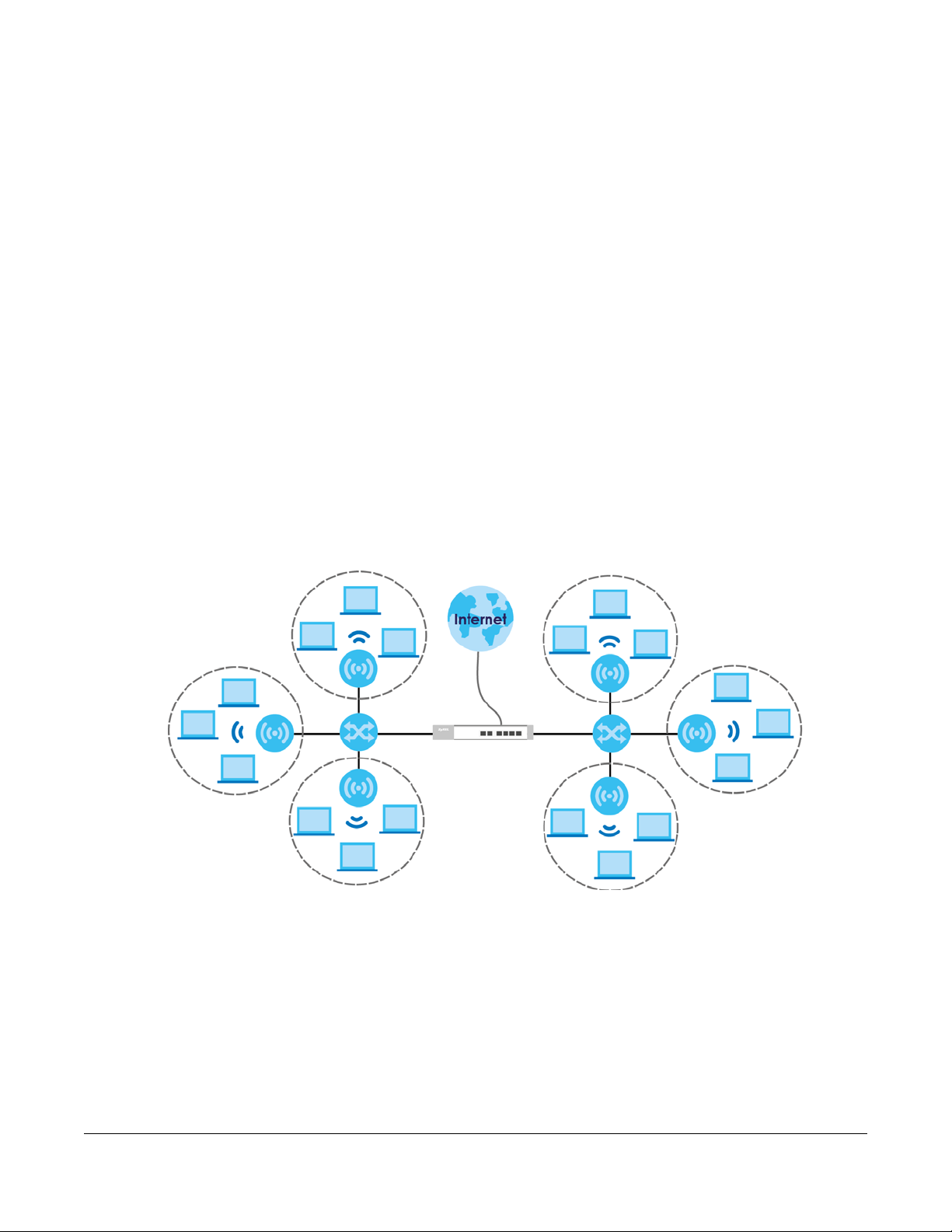
AP Management
A
B
C
D
This chapter shows you how to configure wireless AP management options on your NXC.
8.1 AP Management Overview
The NXC allows you to remotely manage all of the Access Points (APs) on your network. You can
manage a number of APs without having to configure them individually as the NXC automatically
handles basic configuration for you.
The commands in this chapter allow you to add, delete, and edit the APs managed by the NXC by
means of the CAPWAP protocol. An AP must be moved from the wait list to the management list before
you can manage it. If you do not want to use this registration mechanism, you can disable it and then
any newly connected AP is registered automatically.
CHAPTER 8
Figure 11 Example AP Management
In this example, the NXC (A) connects up to a number of Power over Ethernet switches, such as the ES2025 PWR (B). They connect to the NWA/WAC/WAX Access Points (C), which in turn provide access to
the network for the wireless clients within their broadcast radius.
Let’s say one AP (D) starts giving you trouble. You can log into the NXC via console or Telnet and
troubleshoot, such as viewing its traffic statistics or reboot it or even remove it altogether from the list of
viable APs that stations can use.
NXC CLI Reference Guide
69
Page 70

Chapter 8 AP Management
8.2 AP Management Commands
The following table identifies the values required for many of these commands. Other input values are
discussed with the corresponding commands.
Table 30 Input Values for General AP Management Commands
LABEL DESCRIPTION
ap_mac
ap_model
slot_name
profile_name
ap_description
sta_mac
The Ethernet MAC address of the managed AP. Enter 6 hexidecimal pairs separated by
colons. You can use 0-9, a-z and A-Z.
The model name of the managed AP, such as WAC6303D-S or WAC6502D-S.
The slot name for the AP’s on-board wireless LAN card. Use either slot1 or slot2.
The wireless LAN radio profile name. You may use 1-31 alphanumeric characters,
underscores(
case-sensitive.
The AP description. This is strictly used for reference purposes and has no effect on any
other settings. You may use 1-31 alphanumeric characters, underscores(
but the first character cannot be a number. This value is case-sensitive.
The MAC address of the wireless client. Enter 6 hexidecimal pairs separated by colons.
You can use 0-9, a-z and A-Z.
_), or dashes (-), but the first character cannot be a number. This value is
_), or dashes (-),
The following table describes the commands available for AP management. You must use the
configure terminal command to enter the configuration mode before you can use these
commands.
Table 31 Command Summary: AP Management
COMMAND DESCRIPTION
capwap ap ap_mac
slot_name ap-profile profile_name
no slot_name ap-profile
slot_name monitor-profile
profile_name
no slot_name monitor-profile
slot_name output-power <0dBm, 1dBm,
... 30dBm>
slot_name {root-ap | repeater-ap}
ap-profile_name
slot_name ssid-profile <1..8> ssidprofile_name
Enters the sub-command mode for the specified AP.
Sets the radio (slot_name) to AP mode and assigns a
created AP profile to the radio.
Removes the AP mode profile assignment for the
specified radio (slot_name).
Sets the specified radio (slot_name) to monitor mode
and assigns a created monitor mode profile to the radio.
Monitor mode APs act as wireless monitors, which can
detect rogue APs and help you in building a list of
friendly ones. See also Section 10.2 on page 87.
Removes the monitor mode profile assignment for the
specified radio (slot_name).
Sets the maximum output power of the specified radio.
Sets the specified radio (slot_name) to root AP or
repeater mode and assigns a created AP profile to the
radio.
Associates up to eight SSID profiles with the specified AP
radio.
NXC CLI Reference Guide
70
Page 71

Chapter 8 AP Management
Table 31 Command Summary: AP Management (continued)
COMMAND DESCRIPTION
slot_name wireless-bridge {enable |
disable}
slot_name zymesh-profile
profile_name
selectable-antenna config {ceiling |
wall}
antenna config slot_name chain3
{ceiling | wall}
[no] antenna sw-control enable
ap-group-profile ap-group-
Enables or disables wireless bridging on the specified
radio (slot_name). The managed AP must support LAN
provision and the radio should be in repeater mode.
VLAN and bridge interfaces are created automatically
according to the LAN port’s VLAN settings.
When wireless bridging is enabled, the managed
repeater AP can still transmit data through its Ethernet
port(s) after the ZyMesh link is up. Be careful to avoid
bridge loops.
The managed APs in the same ZyMesh must use the
same static VLAN ID.
Specifies the ZyMesh profile the radio uses to connect to
a root AP or repeater. See also Section 10.7 on page 106
for more information about ZyMesh.
Adjust antenna orientation for all radios of an AP for
better coverage.
Select Wall if you mount the AP on a wall. Select Ceiling
if the AP is mounted on a ceiling.
Adjust antenna orientation for a selected radio of an AP
for better coverage.
Select Wall if you mount the AP on a wall. Select Ceiling
if the AP is mounted on a ceiling.
Enables the adjustment of coverage depending on the
orientation of the antenna for the AP radios using the
web configurator or the command line interface (CLI).
The no command disables adjustment through the web
configurator or the command line interface (CLI). You
can still adjust coverage using a physical antenna
switch.
Sets the AP group to which the AP belongs.
profile_name
[no] ap-mode detection activate
cloud interface ip address ip
netmask
cloud interface ip address dhcp
cloud interface ip dns ip
cloud interface ip gateway ip
cloud interface vlan <1..4094> {tag
| untag}
cloud mode
description ap_description
Sets the AP to detect Rogue APs in the network.
The no command disables rogue AP detection.
Manually sets an IP address for the AP in Nebula cloud
management mode.
Sets the AP in Nebula cloud management mode to act
as a DHCP client.
Sets a DNS server address for the AP in Nebula cloud
management mode.
Sets a gateway address for the AP in Nebula cloud
management mode.
Sets a management VLAN ID for the AP in Nebula cloud
management mode and sets whether the AP adds the
VLAN ID to outbound traffic transmitted through its
Ethernet port.
Sets th e AP to work in Nebula cloud management
mode and removes it from the managed AP list.
Sets the description for the specified AP.
NXC CLI Reference Guide
71
Page 72

Chapter 8 AP Management
Table 31 Command Summary: AP Management (continued)
COMMAND DESCRIPTION
[no] force ip
[no] force vlan
fw-updating
ip address ip
ip address dhcp
ip dns ip
ip gateway ip
ip no dns
ip no gateway
lan-provision lan_port {activate |
inactivate} pvid <1..4094>
lan-provision vlan_interface
{activate | inactivate} vid
<1..4094> join lan_port {tag |
untag} [lan_port {tag | untag}]
[lan_port {tag | untag}]
[no] override-full-power activate
Sets whether or not the NXC changes the AP’s IP settings
to match the ones you configure using the ip subcommand.
This takes priority over the AP’s CAPWAP client
commands described in Chapter 42 on page 252.
Sets whether or not the NXC changes the AP’s
management VLAN to match the one you configure
using the vlan sub-command. The management VLAN
on the NXC and AP must match for the NXC to manage
the AP.
This takes priority over the AP’s CAPWAP client
commands described in Chapter 42 on page 252.
Updates the APs’ firmware to the NXC’s latest supported
version.
Manually sets an IP address for the AP.
Sets the AP to act as a DHCP client.
Sets a DNS server address for the AP.
Sets a gateway address for the AP.
Removes the specified DNS server address.
Removes the specified gateway IP address.
Sets the NXC to enable or disable the specified LAN port
on the AP and configures a PVID (Port VLAN ID) for this
port.
lan_port: the name of the AP’s LAN port (lan1 for
example).
Sets the NXC to create a new VLAN or configure an
existing VLAN. You can disable or enable the VLAN, set
the VLAN ID, assign up to three ports to this VLAN as
members and set whether the port is to tag outgoing
traffic with the VLAN ID.
vlan_interface: the name of the VLAN (vlan1 for
example).
Forces the AP to draw full power from the power
sourcing equipment. This improves performance in cases
when a PoE injector that does not support PoE
negotiation is used.
[no] load-balancing <group1 |
group2> group_name
[no] location location
[no] override slot_name {outputpower | radio-setting | ssidsetting}
NXC CLI Reference Guide
Use the no command to disable this feature.
Assigns a load balancing group to the AP.
Use the no command to remove the group1 or group2
assignment of the AP.
Sets the name of the place where the AP is located.
Use the no command to remove the specified settings.
Sets the NXC to overwrite the AP’s output power, radio
or SSID profile settings for the specified radio.
Use the no command to not overwrite the specified
settings.
72
Page 73

Chapter 8 AP Management
Table 31 Command Summary: AP Management (continued)
COMMAND DESCRIPTION
[no] override ap-mode detectionsetting
[no] override lan-provision
[no] override vlan-setting
[no] roaming group roaminggroup
[no] sysname sysname
vlan <1..4094> {tag | untag}
exit
capwap ap ac-ip {primary_ac_ip}
{secondary_ac_ip}
capwap ap ac-ip auto
capwap ap add ap_mac [ap_model]
capwap ap factory default ap_mac
capwap ap fallback disable
capwap ap fallback enable
Sets the NXC to overwrite the AP’s rogue AP detection
settings.
Use the no command to not overwrite the specified
settings.
Sets the NXC to overwrite the AP’s LAN port settings.
Use the no command to not overwrite the specified
settings.
Sets the NXC to overwrite the AP’s VLAN settings.
Use the no command to not overwrite the specified
settings.
Sets the name of the roaming group to which the AP
belongs.
The 802.11k neighbor list a client requests from the AP is
generated according to the roaming group and RCPI
(Received Channel Power Indicator) value of its
neighbor APs.
When a client wants to roam from the current AP to
another, other APs in the same roaming group or not in a
roaming group will be candidates for roaming. Neighbor
APs in a different roaming gr oup will be excluded from
the 802.11k neighbor lists even when the neighbor AP
has the best signal strength.
If the AP’s roaming group is not configured, any
neighbor APs can be candidates for roaming.
Use the no command to remove the specified settings.
Sets a name to identify the AP on a network. This is
usually the AP’s fully qualified domain name.
Use the no command to remove the specified settings.
Sets the VLAN ID for the specified AP as well as whether
packets sent to and from that ID are tagged or
untagged.
Exits the sub-command mode for the specified AP.
Specifies the primary and secondary IP address or
domain name of the AP controller (the NXC) to which
the AP connects.
Sets the AP to use DHCP to get the address of the AP
controller (the NXC).
Adds the specified AP to the NXC for management. If
manual add is disabled, this command can still be used;
if you add an AP before it connects to the network, then
this command simply preconfigures the management list
with that AP’s information.
Resets the specified AP to its factory default settings.
Sets the managed AP(s) to not change back to
associate with the primary AP controller when the
primary AP controller is available.
Sets the managed AP(s) to change back to associate
with the primary AP controller as soon as the primary AP
controller is available.
NXC CLI Reference Guide
73
Page 74

Chapter 8 AP Management
Table 31 Command Summary: AP Management (continued)
COMMAND DESCRIPTION
capwap ap fallback interval <30..86400>
capwap ap kick {all | ap_mac}
capwap ap led-off ap_mac
capwap ap led-on ap_mac
capwap ap reboot ap_mac
capwap ap-group ap_group_profile_name
fw-updating
capwap firmware-update apply
capwap firmware-update check
capwap fw-updating method {capwap | ftp}
Sets how often (in seconds) the managed AP(s) check
whether the primary AP controller is available.
Removes the specified AP (ap_mac) or all connected
APs (all) from the management list. Doing this removes
the AP(s) from the management list.
If the NXC is set to automatically add new APs to the AP
management list, then any kicked APs are added back
to the management list as soon as they reconnect.
Sets the LEDs of the specified AP to turn off after it’s
ready.
Sets the LEDs of the specified AP to stay lit after the NXC
is ready.
Forces the specified AP (ap_mac) to restart. Doing this
severs the connections of all associated stations.
Upgrades the firmware of the APs in the specified AP
group to the NXC’s latest supported version.
Sets the NXC to download the latest AP firmware from
the firmware server.
Checks the firmware server to see if there is any new AP
firmware available.
Sets how you want the NXC to upgrade AP firmware.
capwap: have the NXC use CAPWAP to automatically
update firmware on the managed APs.
ftp: allow the managed APs to download the latest
firmware from the NXC using FTP.
capwap fw-updating mode {auto | manual}
Sets whether a managed AP’s firmware is updated
automatically.
capwap manual-add {enable | disable}
capwap station kick sta_mac
show capwap ap {all | ap_mac}
show capwap ap {all | ap_mac} config
status
show capwap ap ap_mac slot_name detail
show capwap ap ac-ip
NXC CLI Reference Guide
auto: the NXC checks the AP’s firmware version and
updates it automatically to the NXC’s latest supported
version.
manual: you use the commands or web configurator to
update the AP firmware manually.
Allows the NXC to either automatically add new APs to
the network (disable) or wait until you manually confirm
them (enable).
Forcibly disconnects the specified station from the
network.
Displays information of all managed APs (all) or
information of an AP on the Specified MAC address
(ap_mac).
Displays whether or not any AP’s configuration or the
specified AP’s configuration is in conflict with the NXC’s
settings for the AP and displays the settings in conflict if
there are any.
Displays details for the specified radio (slot_name) on
the specified AP (ap_mac).
Displays the address of the NXC or auto if the AP finds
the NXC through broadcast packets.
74
Page 75

Chapter 8 AP Management
Table 31 Command Summary: AP Management (continued)
COMMAND DESCRIPTION
show capwap ap all statistics
show capwap ap fallback
show capwap ap fallback interval
show capwap ap firmware
show capwap ap info
show capwap ap wait-list
show capwap fw-updating info
show capwap manual-add
show capwap station all
show country-code list
show default country-code
show wlan channels {11A|11G} [cw {20|20/
40|20/40/80}] [country country_code]
[indoor|outdoor]
show lan-provision ap ap_mac interface
{lan_port | vlan_interface | all|
ethernet | uplink | vlan}
Displays radio statistics for all A Ps on the management
list.
Displays whether the managed AP(s) will change back
to associate with the primary AP controller when the
primary AP controller is available.
Displays the interval for how often the managed AP(s)
check whether the primary AP controller is available.
Displays the firmware version of the managed AP the
NXC currently has.
Displays the number of managed APs which are
currently connected to the NXC or go offline and the
number of wireless clients.
Displays a list of connected but as-of-yet unmanaged
APs. This is known as the ‘wait list’.
Displays the number of APs doing firmware update, their
method and mode used to update firmware. This also
displays the latest AP firmware version currently on the
NXC and the status of the last firmware check.
Displays the current manual add option.
Displays information for all stations connected to the APs
on the management list.
Displays a reference list of two-letter country codes.
Displays the default country code configured on the
NXC.
Displays the channels available for the specified
frequency band, channel width, and/or country. You
can also specify whether the channels are for indoor or
outdoor use.
Displays the port and/or VLAN settings for the specified
AP.
You can also set to display settings for a specified port, a
specified VLAN, all physical Ethernet ports, the uplink
port or all VLANs on the AP.
8.2.1 AP Management Commands Example
The following example shows you how to add an AP to the management list, and then edit it.
Router# show capwap ap wait-list
index: 1
IP: 192.168.1.35, MAC: 00:11:11:11:11:FE
Model: NWA5160N, Description: AP-00:11:11:11:11:FE
index: 2
IP: 192.168.1.36, MAC: 00:19:CB:00:BB:03
Model: NWA5160N, Description: AP-00:19:CB:00:BB:03
Router# configure terminal
Router(config)# capwap ap add 00:19:CB:00:BB:03
Router(config)# capwap ap 00:19:CB:00:BB:03
Router(AP 00:19:CB:00:BB:03)# slot1 ap-profile approf01
Router(AP 00:19:CB:00:BB:03)# exit
NXC CLI Reference Guide
75
Page 76

Chapter 8 AP Management
The following example shows you part of the information that the command show capwap ap all will
show.
Router> show capwap ap all
index: 1
Status: RUN
IP: 10.253.41.39, MAC: 4C:9E:FF:90:B1:C0
Description: Mark_Test
Model: WAC6502D-S
CPU Usage: 5 %
R1 mode: AP, R1Prof: Mark_24G_US
R2 mode: AP, R2Prof: Mark_5G_US
AP Group Profile: Mark_test
Override Slot1 Radio Profile: disable
Override Slot1 SSID Profile: disable
slot1-SSID Profile 1:
slot1-SSID Profile 2:
slot1-SSID Profile 3:
slot1-SSID Profile 4:
slot1-SSID Profile 5:
slot1-SSID Profile 6:
slot1-SSID Profile 7:
slot1-SSID Profile 8:
Override Slot1 Output Power: disable
Slot1 Output Power: 10dBm
Override Slot2 Radio Profile: disable
Override Slot2 SSID Profile: disable
slot2-SSID Profile 1: Mark_Test
slot2-SSID Profile 2: Mark_Test_Local
slot2-SSID Profile 3:
slot2-SSID Profile 4:
slot2-SSID Profile 5:
NXC CLI Reference Guide
76
Page 77

Chapter 8 AP Management
The following example shows you part of the information that the command show capwap ap_mac will
show.
Router> show capwap ap BC:CF:4F:56:BD:DF
index: 1
Status: RUN
IP: 10.50.40.5, MAC: BC:CF:4F:56:BD:DF
Description: WAX650S-LOC-RDFT
Model: WAX650S
CPU Usage: 22 %
R1 mode: AP, R1Prof: RADIO_24G_Taiwan
R2 mode: AP, R2Prof: RADIO_5G_Taiwan
AP Group Profile: RDFT_LOC
Override Slot1 Radio Profile: disable
Override Slot1 SSID Profile: disable
slot1-SSID Profile 1: LOC-24G-CP3
slot1-SSID Profile 2: virtual_ssid-loc24_2
slot1-SSID Profile 3: virtual_ssid-loc24_3
slot1-SSID Profile 4: virtual_ssid-loc24_4
slot1-SSID Profile 5: virtual_ssid-loc24_5
slot1-SSID Profile 6: virtual_ssid-loc24_6
slot1-SSID Profile 7: virtual_ssid-loc24_7
slot1-SSID Profile 8: virtual_ssid-loc24_8
Override Slot1 Output Power: disable
Slot1 Output Power: 17dBm
Override Slot2 Radio Profile: disable
Override Slot2 SSID Profile: disable
slot2-SSID Profile 1: virtual_ssid-loc5_1
slot2-SSID Profile 2: LOC-5G-CP1
slot2-SSID Profile 3: LOC-5G-CP2
slot2-SSID Profile 4: virtual_ssid-loc5_4
slot2-SSID Profile 5: virtual_ssid-loc5_5
slot2-SSID Profile 6: virtual_ssid-loc5_6
slot2-SSID Profile 7: virtual_ssid-loc5_7
slot2-SSID Profile 8: virtual_ssid-loc5_8
Override Slot2 Output Power: disable
Slot2 Output Power: 17dBm
Station: 5, RadioNum: 2
Override VLAN Setting: disable
Mgmt. VLAN ID: 1, Tag: no
WTP VLAN ID: 1, WTP Tag: no
Force VLAN: disable
Support Lan-provision: yes
Override LAN Provision: disable
Firmware Version: 6.00(ABRM.5)b3
NXC CLI Reference Guide
77
Page 78

The following example displays the management list and radio statistics for the specified AP.
Router(config)# show capwap ap all
index: 1
Status: RUN
IP: 192.168.1.37, MAC: 60:31:97:82:F5:AF
Description: AP-60319782F5AF
Model: WAC5302D-S
CPU Usage: 12 %
R1 mode: AP, R1Prof: default
R2 mode: AP, R2Prof: default2
AP Group Profile: default
Override Slot1 Radio Profile: disable
Override Slot1 SSID Profile: disable
slot1-SSID Profile 1: default
slot1-SSID Profile 2:
slot1-SSID Profile 3:
slot1-SSID Profile 4:
slot1-SSID Profile 5:
slot1-SSID Profile 6:
slot1-SSID Profile 7:
slot1-SSID Profile 8:
Override Slot1 Output Power: disable
Slot1 Output Power: 30dBm
Override Slot2 Radio Profile: disable
Override Slot2 SSID Profile: disable
slot2-SSID Profile 1: default
slot2-SSID Profile 2:
slot2-SSID Profile 3:
slot2-SSID Profile 4:
slot2-SSID Profile 5:
slot2-SSID Profile 6:
slot2-SSID Profile 7:
slot2-SSID Profile 8:
Override Slot2 Output Power: disable
Slot2 Output Power: 30dBm
Station: 2, RadioNum: 2
Override VLAN Setting: disable
Mgnt. VLAN ID: 1, Tag: no
WTP VLAN ID: 1, WTP Tag: no
Force VLAN: disable
Support Lan-provision: yes
Override LAN Provision: disable
Firmware Version: 5.30(AASE.0)b6
Primary AC IP: broadcast
Secondary AC IP: N/A
Recent On-line Time: 2018/06/26 04:08:16
Last Off-line Time: 2018/06/26 04:08:16
Loop State: N/A
LED Status: N/A
Suppress Mode Status: Enable
Locator LED Status: N/A
Locator LED Time: 0
Locator LED Time Lease: 0
Power Mode: Full
Antenna Switch SW-Control: N/A
Antenna Switch Radio 1: N/A
Antenna Switch Radio 2: N/A
NXC CLI Reference Guide
78
Page 79

Chapter 8 AP Management
Compatible: No
Capability: 582
Port Number: 2
Conflict: n/a
Non-support: n/a
Slot1-BLE-status: N/A
Override AP-mode Detection: enable
AP-mode Detection: no
Ethernet Uplink: N/A
System Name: ZyxelTW
Location: Zyxel 1F
S/N: S162L31240135
Roaming Group:
Load-Balancing Group1:
Load-Balancing Group2:
NebulaFlex PRO: No
Support Factory Default: No
Packet Capture Capability: No
Force IP: disable
Config IP Status: dhcp
Config IP Address: n/a
Config IP Mask: n/a
Config IP Gateway: n/a
Config IP DNS: n/a
Storming: N/A
Override full power: N/A
Router(config)# show capwap ap 60:31:97:82:F5:AF slot1 detail
index: 1
SSID: Zyxel
BSSID: 60:31:97:82:F5:B0
SecMode: NONE, Forward Mode: Local Bridge, Vlan: 1
Router(config)# show capwap ap all statistics
index: 1
Status: RUN, Loading: -
AP MAC: 60:31:97:82:F5:AF
Radio: 1, OP Mode: AP
Profile: default, MAC: F0:FD:F0:FD:F0:FD
Description: AP-60319782F5AF
Model: WAC5302D-S
Band: 2.4GHz, Channel: 6
Station: 0
Rx: 101395, Tx: 866288
RxFCS: 42803, TxRetry: 897
TxPower: 15 dBm
Antenna Type: N/A
index: 2
Status: RUN, Loading: AP MAC: 60:31:97:82:F5:AF
Radio: 2, OP Mode: AP
Profile: default2, MAC: F0:FD:F0:FD:F0:FD
Description: AP-60319782F5AF
Model: WAC5302D-S
Band: 5GHz, Channel: 36/40
Station: 2
Rx: 864251, Tx: 1076862
RxFCS: 169608, TxRetry: 2816
TxPower: 16 dBm
Antenna Type: N/A
Router(config)#
NXC CLI Reference Guide
79
Page 80

Chapter 9 AP Group
CHAPTER 9
This chapter shows you how to configure AP groups, which define the radio, port, VLAN and load
balancing settings and apply the settings to all APs in the group. An AP can belong to one AP group at
a time.
9.1 Wireless Load Balancing Overview
Wireless load balancing is the process whereby you limit the number of connections allowed on an
wireless access point (AP) or you limit the amount of wireless traffic transmitted and received on it.
Because there is a hard upper limit on the AP’s wireless bandwidth, this can be a crucial function in
areas crowded with wireless users. Rather than let every user connect and subsequently dilute the
available bandwidth to the point where each connecting device receives a meager trickle, the load
balanced AP instead limits the incoming connections as a means to maintain bandwidth integrity.
AP Group
9.2 AP Group Commands
The following table identifies the values required for many of these commands. Other input values are
discussed with the corresponding commands.
Table 32 Input Values for General AP Management Commands
LABEL DESCRIPTION
ap_group_profile
_name
slot
The following table describes the commands available for AP groups. You must use the
terminal
Table 33 Command Summary: AP Group
COMMAND DESCRIPTION
ap-group first-priority
ap_group_profile_name
ap-group flush wtp-setting
ap_group_profile_name
command to enter the configuration mode before you can use these commands.
The wireless LAN radio profile name. You may use 1-31 alphanumeric characters,
underscores(
case-sensitive.
The slot name for the AP’s on-board wireless LAN card. Use either slot1 or slot2.
_), or dashes (-), but the first character cannot be a number. This value is
configure
Sets an AP group file that is used as the default group file.
Any AP that is not configured to associate with a specific
AP group belongs to the default group automatically.
Sets the NXC to overwrite the settings of all managed APs in
the specified group with the group profile settings.
NXC CLI Reference Guide
80
Page 81

Chapter 9 AP Group
Table 33 Command Summary: AP Group (continued)
COMMAND DESCRIPTION
ap-group-member ap_group_profile_name
[no] member mac_address
[no] ap-group-profile
ap_group_profile_name
[no] slot ap-profile
radio_profile_name
[no] slot monitor-profile
monitor_profile_name
[no] slot output-power wlan_power
[no] slot repeater-ap
radio_profile_name
[no] slot root-ap
radio_profile_name
[no] slot ssid-profile <1..8>
ssid_profile_name
Specifies the MAC address of the AP that you want to
apply the specified AP group profile and add to the group.
Use the no command to remove the specified AP from this
group.
Enters configuration mode for the specified AP group
profile. Use the no command to remove the specified
profile.
Sets the specified radio to work as an AP and specifies the
radio profile the radio is to use.
Use the no command to remove the specified profile.
Sets the specified radio to work in mo nitor mode and
specifies the monitor profile the radio is to use.
Use the no command to remove the specified profile.
Sets the output power (between 0 to 30 dBm) for the radio
on the AP that belongs to this group.
Use the no command to remove the output power setting.
Sets the specified AP radio to work as a repeater and
specifies the radio profile the radio is to use.
Use the no command to remove the specified profile.
Sets the specified radio to work as a root AP and specifies
the radio profile the radio is to use.
A root AP supports the wireless connections with other APs
(in repeater mode) to form a ZyMesh to extend its wireless
network.
Use the no command to remove the specified profile.
Sets the SSID profile that is associated with this profile.
You can associate up to eight SSID profiles with an AP
radio.
[no] slot zymesh-profile
zymesh_profile_name
description description
exit
[no] force vlan
NXC CLI Reference Guide
Use the no command to remove the specified profile.
Sets the ZyMesh profile the radio (in root AP or repeater
mode) uses to connect to a root AP or repeater.
Use the no command to remove the specified profile.
Sets a description for this group. You can use up to 31
characters, spaces and underscores allowed.
Use the no command to remove the specified description.
Exits configuration mode for this profile.
Sets the NXC to change the AP’s management VLAN to
match the configuration in this profile.
Use the no command to not change the AP’s
management VLAN setting.
81
Page 82

Chapter 9 AP Group
Table 33 Command Summary: AP Group (continued)
COMMAND DESCRIPTION
[no] lan-provision model ap_model
ap_lan_port activate pvid
<1..4094>
Sets the model of the managed AP and enable the modelspecific LAN port and configure the port VLAN ID.
Use the no command to remove the specified port and
VLAN settings.
ap_lan_port: the Ethernet LAN port on the managed AP,
such as lan1 or lan2.
ap_model: the model name you want to configure. Use "-"
instead of spaces. Examples are:
wac6503d-s,
[no] lan-provision model ap_model
ap_lan_port inactivate pvid
<1..4094>
Sets the model of the managed AP and disable the modelspecific LAN port and configure the port VLAN ID.
Use the no command to remove the specified port and
VLAN settings.
ap_lan_port: the Ethernet LAN port on the managed AP,
such as lan1 or lan2.
ap_model: the model name you want to configure. Use "-"
instead of spaces. Examples are:
wac6503d-s,
[no] lan-provision model ap_model
vlan_interface activate vid
<1..4094> join ap_lan_port {tag |
untag} [ap_lan_port {tag | untag}]
[ap_lan_port {tag | untag}]
Sets the model of the managed AP, enable a VLAN and
configure the VLAN ID. It also sets the Ethernet port(s) on
the managed AP to be a member of the VLAN, and sets
the port(s) to send packets with or without a VLAN tag.
Use the no command to remove the specified port and
VLAN settings.
nwa5123-achd,
and wac6552d-s.
nwa5123-ac-hd,
and wac6552d-s.
[no] lan-provision model ap_model
vlan_interface inactivate vid
<1..4094> join ap_lan_port {tag |
untag} [ap_lan_port {tag | untag}]
[ap_lan_port {tag | untag}]
[no] load-balancing [slot1 |
slot2] activate
vlan_interface: the name of the VLAN, such as vlan0.
ap_lan_port: the Ethernet LAN port on the managed AP,
such as lan1 or lan2.
ap_model: the model name you want to configure. Use "-"
instead of spaces. Examples are:
wac6503d-s,
Sets the model of the managed AP, disable a VLAN and
configure the VLAN ID. It also sets the Ethernet port(s) on
the managed AP to be a member of the VLAN, and sets
the port(s) to send packets with or without a VLAN tag.
Use the no command to remove the specified port and
VLAN settings.
vlan_interface: the name of the VLAN, such as vlan0.
ap_lan_port: the Ethernet LAN port on the managed AP,
such as lan1 or lan2.
ap_model: the model name you want to configure. Use "-"
instead of spaces. Examples are:
wac6503d-s,
Enables load balancing. Use the no parameter to disable it.
Optionally specify a radio slot.
and wac6552d-s.
and wac6552d-s.
nwa5123-ac-hd,
nwa5123-ac-hd,
NXC CLI Reference Guide
82
Page 83

Chapter 9 AP Group
Table 33 Command Summary: AP Group (continued)
COMMAND DESCRIPTION
load-balancing [slot1 | slot2]
alpha <1..255>
Sets the load balancing alpha value.
When the AP is balanced, then this setting delays a client’s
association with it by this numb er of seconds.
Note: This parameter has been optimized for the
NXC and should not be changed unless you
have been specifically directed to do so by
Zyxel support.
load-balancing [slot1 | slot2]
beta <1..255>
Sets the load balancing beta value.
When the AP is overloaded, then this setting delays a
client’s association with it by this number of seconds.
Note: This parameter has been optimized for the
NXC and should not be changed unless you
have been specifically directed to do so by
Zyxel support.
load-balancing [slot1 | slot2]
kickInterval <1..255>
[no] load-balancing [slot1 |
slot2] kickout
load-balancing [slot1 | slot2]
liInterval <1..255>
Enables the kickout feature for load balancing and also
sets the kickout interval in seconds. While load balancing is
enabled, the AP periodically disconnects stations at
intervals equal to this setting.
This occurs until the load balancing threshold is no longer
exceeded.
Enables an overloaded AP to disconnect (“kick”) idle
clients or clients with noticeably weak connections.
Sets the interval in seconds that each AP communicates
with the other APs in its range for calculating the load
balancing algorithm.
load-balancing [slot1 | slot2] max
sta <1..127>
load-balancing [slot1 | slot2]
mode {station | traffic | smartclassroom}
Note: This parameter has been optimized for the
NXC and should not be changed unless you
have been specifically directed to do so by
Zyxel support.
If load balancing by the number of stations/wireless clients,
this sets the maximum number of devices allowed to
connect to a load-balanced AP.
Enables load balancing based on either number of stations
(also known as wireless clients) or wireless traffic on an AP.
station or traffic: once the threshold is crossed (either the
maximum station numbers or with network traffic), the AP
delays association request and authentication request
packets from any new station that attempts to make a
connection.
smart-classroom: the AP ignores association request and
authentication request packets from any new station when
the maximum number of stations is reached.
NXC CLI Reference Guide
83
Page 84

Chapter 9 AP Group
Table 33 Command Summary: AP Group (continued)
COMMAND DESCRIPTION
load-balancing [slot1 | slot2]
sigma <51..100>
Sets the load balancing sigma value.
This value is algorithm parameter used to calculate
whether an AP is considered overloaded, balanced, or
underloaded. It only applies to ‘by traffic mode’.
Note: This parameter has been optimized for the
NXC and should not be changed unless you
have been specifically directed to do so by
Zyxel support.
load-balancing [slot1 | slot2]
timeout <1..255>
load-balancing [slot1 | slot2]
traffic level {high | low |
Sets the length of time that an AP retains load balancing
information it receives from other APs within its range.
If load balancing by traffic threshold, this sets the traffic
threshold level.
medium}
[no] location location
vlan <1..4094> {tag | untag}
show ap-group first-priority
show ap-group-profile {all |
ap_group_profile_name}
show ap-group-profile
ap_group_profile_name ap-mode
Sets the name of the place where the AP group is located.
Use the no command to remove the location setting.
Sets the management VLAN ID for the AP(s) in this group as
well as whether packets sent to and from that VLAN ID are
tagged or untagged.
Displays the name of the default AP group profile.
Displays the settings of the AP group profile(s).
all: Displays all profiles.
ap_group_profile_name: Displays the specified profile.
Displays the AP-mode rogue AP detection configuration of
the specified AP group profile.
detection config
show ap-group-profile
ap_group_profile_name load-balancing
Displays the load balancing configuration of the specified
AP group profile.
config
show ap-group-profile
ap_group_profile_name lan-provision
model ap_model interface {all | vlan |
ethernet | ap_lan_port |
vlan_interface}
Displays the LAN port and/or VLAN settings on the
managed AP which is in the specified AP group and of the
specified model.
vlan_interface: the name of the VLAN, such as vlan0.
ap_lan_port: the Ethernet LAN port on the managed AP,
such as lan1 or lan2.
ap_model: the model name you want to configure. Use "-"
instead of spaces. Examples are:
wac6503d-s,
show ap-group-profile
ap_group_profile_name lan-provision
Shows the model name of the managed AP which belongs
to the specified AP group.
model
show ap-group-profile rule_count
capwap ap-group ap_group_profile_name
fw-updating
Displays how many AP group profiles have been
configured on the NXC.
Forces the APs in a specified AP group
(ap_group_profile_name) to upgrade their firmware.
and wac6552d-s.
nwa5123-ac-hd,
NXC CLI Reference Guide
84
Page 85

Table 33 Command Summary: AP Group (continued)
COMMAND DESCRIPTION
capwap ap-group reboot
ap_group_profile_name
ap-group-profile rename
ap_group_profile_name1
ap_group_profile_name2
9.2.1 AP Group Examples
The following example shows you how to create an AP group profile (named “TEST”) and configure the
AP’s first radio to work in repeater mode using the “default” radio profile and the “ZyMesh_TEST” ZyMesh
profile. It also adds the AP with the MAC address 00:a0:c5:01:23:45 to this AP group.
Router(config)# ap-group-profile TEST
Router(config-ap-group TEST)# slot1 repeater-ap default
Router(config-ap-group TEST)# slot1 zymesh-profile ZyMesh_TEST
Router(config-ap-group TEST)# exit
Router(config)# ap-group-member TEST member 00:a0:c5:01:23:45
Router(config)#
The following example shows you how to create an AP group profile (named GP1) and configure AP
load balancing in "by station" mode. The maximum number of stations is set to 1.
Forces the APs in a specified AP group
(ap_group_profile_name) to restart. Doing this severs the
connections of all associated stations.
Gives an existing AP group profile
(ap_group_profile_name1) a new name
(ap_group_profile_name2).
Router(config)# ap-group-profile GP1
Router(config-ap-group GP1)# load-balancing mode station
Router(config-ap-group GP1)# load-balancing max sta 1
Router(config-ap-group GP1)# exit
Router(config)# show ap-group-profile GP1 load-balancing config
AP Group Profile:GP1
load balancing config slot1:
Activate: no
Kickout: no
Mode: station
Max-sta: 1
Traffic-level: high
Alpha: 5
Beta: 10
Sigma: 60
Timeout: 20
LIInterval: 10
KickoutInterval: 10
load balancing config slot2:
Activate: no
Kickout: no
Mode: station
Max-sta: 1
Traffic-level: high
Alpha: 5
Beta: 10
Sigma: 60
Timeout: 20
LIInterval: 10
KickoutInterval: 10
Router(config)#
NXC CLI Reference Guide
85
Page 86

Chapter 9 AP Group
The following example shows you how to create an AP group profile (named GP2) and configure AP
load balancing in "by traffic" mode. The traffic level is set to low, and "disassociate station" is enabled.
Router(config)# ap-group-profile GP2
Router(config-ap-group GP2)# load-balancing mode traffic
Router(config-ap-group GP2)# load-balancing traffic level low
Router(config-ap-group GP2)# load-balancing kickout
Router(config-ap-group GP2)# exit
Router(config)# show ap-group-profile GP2 load-balancing config
AP Group Profile:GP2
load balancing config slot1:
Activate: no
Kickout: yes
Mode: traffic
Max-sta: 127
Traffic-level: low
Alpha: 5
Beta: 10
Sigma: 60
Timeout: 20
LIInterval: 10
KickoutInterval: 10
load balancing config slot2:
Activate: no
Kickout: yes
Mode: traffic
Max-sta: 127
Traffic-level: low
Alpha: 5
Beta: 10
Sigma: 60
Timeout: 20
LIInterval: 10
KickoutInterval: 10
Router(config)#
NXC CLI Reference Guide
86
Page 87

Chapter 10 Wireless LAN Profiles
CHAPTER 10
Wireless LAN Profiles
This chapter shows you how to configure wireless LAN profiles on your NXC.
10.1 Wireless LAN Profiles Overview
The managed Access Points designed to work explicitly with your NXC do not have on-board
configuration files, you must create “profiles” to manage them. Profiles are preset configurations that
are uploaded to the APs and which manage them. They include: Radio and Monitor profiles, SSID
profiles, Security profiles, MAC Filter profiles, and Layer-2 isolation profiles. Altogether, these profiles give
you absolute control over your wireless network.
10.2 AP Radio & Monitor Profile Commands
The radio profile commands allow you to set up configurations for the radios onboard your various APs.
The monitor profile commands allow you to set up monitor mode configurations that allow your APs to
scan for other APs in the vicinity.
The following table identifies the values required for many of these commands. Other input values are
discussed with the corresponding commands.
Table 34 Input Values for General Radio and Monitor Profile Commands
LABEL DESCRIPTION
radio_profile_name
monitor_profile_name
interval
wlan_role
wireless_channel_2g
wireless_channel_5g
The radio profile name. You may use 1-31 alphanumeric characters, underscores
(
_), or dashes (-), but the first character cannot be a number. This value is case-
sensitive.
The monitor profile name. You may use 1-31 alphanumeric characters, underscores
(
_), or dashes (-), but the first character cannot be a number. This value is case-
sensitive.
Enters the dynamic channel selection interval time. The range is 10 ~ 1440 minutes.
Sets the wireless LAN radio operating mode. At the time of writing, you can use ap
for Access Point.
Sets the 2 GHz channel used by this radio profile. The channel range is 1 ~ 14.
Note: Your choice of channel may be restricted by regional regulations.
Sets the 5 GHz channel used by this radio profile. The channel range is 36 ~ 165.
wlan_htcw
Note: Your choice of channel may be restricted by regional regulations.
Sets the HT channel width. Select either 20, 20/40 or 20/40/80.
NXC CLI Reference Guide
87
Page 88

Chapter 10 Wireless LAN Profiles
Table 34 Input Values for General Radio and Monitor Profile Commands (continued)
LABEL DESCRIPTION
wlan_htgi
chain_mask
wlan_power
scan_method
wlan_interface_index
ssid_profile
Sets the HT guard interval. Select either long or short.
Sets the network traffic chain mask. The range is 1 ~ 7.
Sets the radio output power.
Sets the radio’s scan method while in Monitor mode. Select manual or auto.
Sets the radio interface index number. The range is 1 ~ 8.
Sets the associated SSID profile name. This name must be an existing SSID profile.
You may use 1-31 alphanumeric characters, underscores (
first character cannot be a number. This value is case-sensiti ve.
_), or dashes (-), but the
The following table describes the commands available for radio and monitor profile management. You
must use the
configure terminal command to enter the configuration mode before you can use
these commands.
Table 35 Command Summary: Radio Profile
COMMAND DESCRIPTION
show wlan-radio-profile {all |
radio_profile_name}
Displays the radio profile(s).
all: Displays all profiles.
wlan-radio-profile rename
radio_profile_name1 radio_profile_name2
[no] wlan-radio-profile
radio_profile_name
2g-channel wireless_channel_2g
5g-channel wireless_channel_5g
2g-multicast-speed
wlan_2g_support_speed
5g-multicast-speed
wlan_5g_basic_speed
[no] activate
radio_profile_name: Displays the specified profile.
Gives an existing radio profile (radio_profile_name1) a
new name (radio_profile_name2).
Enters configuration mode for the specified radio profile.
Use the no parameter to remove the specified profile.
Sets the broadcast band for this profile in the 2.4 GHz
frequency range. The default is 6.
Sets the broadcast band for this profile in the 5 GHz
frequency range. The default is 36.
When you disable multicast to unicast, use this
command to set the data rate {1.0 | 2.0 | …} in
Mbps for 2.4 GHz multicast traffic.
When you disable multicast to unicast, use this
command to set the data rate {6.0 | 9.0 | …} in
Mbps for 5 GHz multicast traffic.
Makes this profile active or inactive.
NXC CLI Reference Guide
88
Page 89

Chapter 10 Wireless LAN Profiles
Table 35 Command Summary: Radio Profile (continued)
COMMAND DESCRIPTION
band {2.4G |5G} band-mode
{bg | bgn | a | ac | an | bgnax |
anacax}
bss-color <0~63>
[no] disable-bss-color
beacon-interval <40..1000>
country-code country_code
Sets the radio band (2.4 GHz or 5 GHz) and band mode
for this profile. Band mode details:
For 2.4 GHz, bg lets IEEE 802.11b and IEEE 802.11g clients
associate with the AP.
For 2.4 GHz, bgn lets IEEE 802.11b, IEEE 802.11g, and IEEE
802.11n clients associate with the AP.
For 2.4 GHz, bgnax lets IEEE 802.11b, IEEE 802.11g, IEEE
802.11n, and IEEE802.11ax clients associate with the AP.
For 5 GHz, a lets only IEEE 802.11a clients associate with
the AP.
For 5 GHz, ac lets IEEE 802.11a, IEEE 802.11n, and IEEE
802.11ac clients associate with the AP.
For 5 GHz, an lets IEEE 802.11a and IEEE 802.11n clients
associate with the AP.
For 5 GHz, anacax lets IEEE 802.11a, IEEE 802.11n, IEEE
802.11ac, and IEEE802.11ax clients associate with the AP.
Sets the BSS color of the AP, which distinguishes it from
other nearby APs when they transmit over the same
channel. Set it to 0 to automatically assign a BSS color.
Disables BSS coloring.
Use the
Sets the beacon interval for this profile.
When a wirelessly networked device sends a beacon, it
includes with it a beacon interval. This specifies the time
period before the device sends the beacon again. The
interval tells receiving devices on the network how long
they can wait in low-power mode before waking up to
handle the beacon. This value can be set from 40ms to
1000ms. A high value helps save current consumption of
the access point.
The default is 100.
Sets the country where the NXC is located/installed.
The available channels vary depending on the country
you selected. Be sure to select the correct/same country
for both radios on an AP and all connected APs, in order
to prevent roaming failure and interference to other
systems.
no command to enable BSS coloring.
[no] dcs activate
dcs 2g-selected-channel
2.4g_channels
dcs 5g-selected-channel 5g_channels
NXC CLI Reference Guide
89
country_code: 2-letter country-codes, such as TW, DE, or
FR.
Starts dynamic channel selection to automatically find a
less-used channel in an environment where there are
many APs and there may be interference. Use the no
parameter to turn it off.
Specifies the channels that are available in the 2.4 GHz
band when you manually configure the channels an AP
can use.
Specifies the channels that are available in the 5 GHz
band when you manually configure the channels an AP
can use.
Page 90

Chapter 10 Wireless LAN Profiles
Table 35 Command Summary: Radio Profile (continued)
COMMAND DESCRIPTION
dcs dcs-2g-method {auto|manual}
dcs dcs-5g-method {auto|manual}
dcs client-aware {enable|disable}
dcs channel-deployment {3channel|4-channel}
dcs dfs-aware {enable|disable}
dcs mode {interval|schedule}
dcs schedule <hh:mm>
{mon|tue|wed|thu|fri|sat|sun}
dcs sensitivity-level {high|medium
|low}
dcs time-interval interval
[no] nol-channel-block
[no] disable-dfs-switch
[no] dot11n-disable-coexistence
Sets the AP to automatically search for available
channels or manually configure the channels the AP uses
in the 2.4 GHz band.
Sets the AP to automatically search for available
channels or manually configure the channels the AP uses
in the 5 GHz band.
When enabled, this ensures that an AP will not change
channels as long as a client is connected to it. If disabled,
the AP may change channels regardless of whether it has
clients connected to it or not.
Sets either a 3-channel deployment or a 4-channel
deployment.
In a 3-channel deployment, the AP running the scan
alternates between the following channels: 1, 6, and 11.
In a 4-channel deployment, the AP running the scan
alternates between the following channels: 1, 4, 7, and 11
(FCC) or 1, 5, 9, and 13 (ETSI).
Sets the option that is applicable to your region.
(Channel deployment may be regulated differently
between countries and locales.)
Enables this to allow an AP to avoid phase DFS channels
below the 5 GHz spectrum.
Sets the AP to use DCS at the end of the specified time
interval or at a specific time on selected days of the
week.
Sets what time of day (in 24-hour format) the AP starts to
use DCS on the specified day(s) of the week.
Sets how sensitive DCS is to radio channel changes in the
vicinity of the AP running the scan.
Sets the interval that specifies how often DCS should run.
Enables or disables temporary DFS channel blacklisting. If
enabled, the AP will block a DFS channel if it detects a
radar signal within that range.
Makes the DFS switch active or inactive. By default this is
inactive.
Fixes the channel bandwidth as 40 MHz. The no
command has the AP automatically choose 40 MHz if all
the clients support it or 20 MHz if some clients only support
20 MHz.
NXC CLI Reference Guide
90
Page 91

Chapter 10 Wireless LAN Profiles
Table 35 Command Summary: Radio Profile (continued)
COMMAND DESCRIPTION
[no] ctsrts <0..2347>
[no] frag <256..2346>
dtim-period <1..255>
Sets or removes the RTS/CTS value for this profile.
Use RTS/CTS to reduce data collisions on the wireless
network if you have wireless clients that are associated
with the same AP but out of range of one another. When
enabled, a wireless client sends an RTS (Request To Send)
and then waits for a CTS (Clear To Send) before it
transmits. This stops w ireless clients from transmitting
packets at the same time (and causing data collisions).
A wireless client sends an RTS for all packets larger than
the number (of bytes) that you enter here. Set the RTS/
CTS equal to or higher than the fragmentation threshold
to turn RTS/CTS off.
The default is 2347.
Sets or removes the fragmentation value for this profile.
The threshold (number of bytes) for the fragmentation
boundary for directed messages. It is the maximum data
fragment size that can be sent.
The default is 2346.
Sets the DTIM period for this profile.
Delivery Traffic Indication Message (DTIM) is the time
period after which broadcast and multicast packets are
transmitted to mobile clients in the Active Power
Management mode. A high DTIM value can cause
clients to lose connectivity with the network. This value
can be set from 1 to 255.
[no] ampdu
limit-ampdu < 100..65535>
subframe-ampdu <2..64>
[no] amsdu
The default is 1.
Activates MPDU frame aggregation for this profile. Use
the no parameter to disable it.
Message Protocol Data Unit (MPDU) aggregation collects
Ethernet frames along with their 802.11n headers and
wraps them in a 802.11n MAC header. This method is
useful for increasing bandwidth throughput in
environments that are prone to high error rates.
By default this is enabled.
Sets the maximum frame size to be aggregated.
By default this is 50000.
Sets the maximum number of frames to be aggregated
each time.
By default this is 32.
Activates MPDU frame aggregation for this profile. Use
the no parameter to disable it.
Mac Service Data Unit (MSDU) aggregation collects
Ethernet frames without any of their 802.11n headers and
wraps the header-less payload in a single 802.11n MAC
header. This method is useful for increasing bandwidth
throughput. It is also more efficient than A-MPDU except
in environments that are prone to high error rates.
By default this is enabled.
NXC CLI Reference Guide
91
Page 92

Chapter 10 Wireless LAN Profiles
Table 35 Command Summary: Radio Profile (continued)
COMMAND DESCRIPTION
limit-amsdu <2290..4096>
[no] multicast-to-unicast
[no] reject-legacy-station
[no] block-ack
ch-width wlan_htcw
guard-interval wlan_htgi
[no] htprotect
output-power wlan_power
role wlan_role
rssi-dbm <-20~-76>
rssi-kickout <-20~-105>
[no] rssi-retry
Sets the maximum frame size to be aggregated.
The default is 4096.
“Multicast to unicast” broadcasts wireless multicast traffic
to all wireless clients as unicast traffic to provide more
reliable transmission. The data rate changes dynamically
based on the application’s bandwidth requirements.
Although unicast provides more reliable transmission of
the multicast traffic, it also produces duplicate packets.
The no command turns multicast to unicast off to send
wireless multicast traffic at the rate you specify with the
2g-multicast-speed or 5g-multicast-speed
command.
Allows only 802.11 n/ac clients to connect, and reject
802.11a/b/g clients.
Use the no command to also allow 802.11a/b/g clients.
Makes block-ack active or inactive. Use the no
parameter to disable it.
Sets the channel width for this profile.
Sets the guard interval for this profile.
The default for this is short.
Activates HT protection for this profile. Use the no
parameter to disable it.
By default, this is disabled.
Sets the output power (between 0 to 30 dBm) for the
radio in this profile.
Sets the profile’s wireless LAN radio operating mode.
When using the RSSI threshold, set a minimum client signal
strength for connecting to the AP. -20 dBm is the strongest
signal you can require and -76 is the weakest.
Sets a minimum kick-off signal strength. When a wireless
client’s signal strength is lower than the specified
threshold, the NXC disconnects the wireless client from
the AP.
-20 dBm is the strongest signal you can require and -105 is
the weakest.
Allows a wireless client to try to associate with the AP
again after it is disconnected due to weak signal
strength.
rssi-retrycount <1~100>
[no] rssi-thres
[no] ssid-profile
wlan_interface_index ssid_profile
tx-mask chain_mask
NXC CLI Reference Guide
92
Use the no parameter to disallow it.
Sets the maximum number of times a wireless client can
attempt to re-connect to the AP.
Sets whether or not to use the Received Signal Strength
Indication (RSSI) threshold to ensure wireless clients
receive good throughput. This allows only wireless clients
with a strong signal to connect to the AP.
Assigns an SSID profile to this radio profile. Requires an
existing SSID profile. Use the no parameter to disable it.
Sets the outgoing chain mask rate.
Page 93

Chapter 10 Wireless LAN Profiles
Table 35 Command Summary: Radio Profile (continued)
COMMAND DESCRIPTION
rx-mask chain_mask
exit
storm-control ethernet ap mac address
[no] broadcast
broadcast pps <1~10000>
[no] multicast
multicast pps <1~10000>
wlan-radio-profile RADIO_PROFILE_NAME
rssi-dbm <signal strength (dBm)>
wlan-radio-profile RADIO_PROFILE_NAME
rssi-kickout <signal strength (dBm)>
Sets the incoming chain mask rate.
Exits configuration mode for this profile.
Enters the storm control sub-command mode for the
specified AP.
Enables or disables broadcast storm control, which drops
broadcast packets from ingress traffic if the traffic rate
exceeds the configured maximum rate.
Sets the maximum rate for broadcast traffic before storm
control starts dropping broadcast packets.
Enables or disables multicast storm control, which drops
multicast packets from ingress traffic if the traffic rate
exceeds the configured maximum rate.
Sets the maximum rate for multicast traffic before storm
control starts dropping multicast packets.
Sets a minimum client signal strength. A wireless client is
allowed to connect to the AP only when its signal
strength is stronger than the specified threshold.
-20 dBm is the strongest signal you can set and -105 is the
weakest.
Sets a minimum kick-off signal strength. When a wireless
client’s signal strength is lower than the specified
threshold, the AP disconnects the wireless client from it.
show storm-control ethernet ap mac
address
show wlan-monitor-profile {all |
monitor_profile_name}
wlan-monitor-profile rename
monitor_profile_name1
monitor_profile_name2
[no] wlan-monitor-profile
monitor_profile_name
[no] activate
country-code country_code
scan-method scan_method
[no] 2g-scan-channel
wireless_channel_2g
-20 dBm is the strongest signal you can set and -105 is the
weakest.
Displays broadcast/multicast storm control settings on the
specified AP.
Displays all monitor profiles or just the specified one.
Gives an existing monitor profile
(monitor_profile_name1) a new name
(monitor_profile_name2).
Enters configuration mode for the specified monitor
profile. Use the no parameter to remove the specified
profile.
Makes this profile active or inactive.
By default, this is enabled.
Sets the country where the NXC is located/installed.
The available channels vary depending on the country
you selected. Be sure to select the correct/same country
for both radios on an AP and all connected APs, in order
to prevent roaming failure and interference to other
systems.
country_code: 2-letter country-codes, such as TW, DE, or
FR.
Sets the channel scanning method for this profile.
Sets the broadcast band for this profile in the 2.4 Ghz
frequency range. Use the no parameter to disable it.
NXC CLI Reference Guide
93
Page 94

Chapter 10 Wireless LAN Profiles
Table 35 Command Summary: Radio Profile (continued)
COMMAND DESCRIPTION
[no] 5g-scan-channel
wireless_channel_5g
scan-dwell <100..1000>
exit
Sets the broadcast band for this profile in the 5 GHz
frequency range. Use the no parameter to disable it.
Sets the duration in milliseconds that the device using this
profile scans each channel.
Exits configuration mode for this profile.
10.2.1 AP Radio & Monitor Profile Commands Example
The following example shows you how to set up the radio profile named ‘RADIO01’, activate it, and
configure it to use the following settings:
• 2.4G band with channel 6
• channel width of 20MHz
• a DTIM period of 2
• a beacon interval of 100ms
• AMPDU frame aggregation enabled
• an AMPDU buffer limit of 65535 bytes
• an AMPDU subframe limit of 64 frames
• AMSDU frame aggregation enabled
• an AMSDU buffer limit of 4096
• block acknowledgement enabled
• a short guard interval
• an output power of 100%
It will also assign the SSID profile labeled ‘default’ in order to create WLAN VAP (wlan-1-1) functionality
within the radio profile.
Router(config)# wlan-radio-profile RADIO01
Router(config-profile-radio)# activate
Router(config-profile-radio)# band 2.4G band-mode bgn
Router(config-profile-radio)# 2g-channel 6
Router(config-profile-radio)# ch-width 20/40
Router(config-profile-radio)# dtim-period 2
Router(config-profile-radio)# beacon-interval 100
Router(config-profile-radio)# ampdu
Router(config-profile-radio)# limit-ampdu 65535
Router(config-profile-radio)# subframe-ampdu 64
Router(config-profile-radio)# amsdu
Router(config-profile-radio)# limit-amsdu 4096
Router(config-profile-radio)# block-ack
Router(config-profile-radio)# guard-interval short
Router(config-profile-radio)# tx-mask 5
Router(config-profile-radio)# rx-mask 7
Router(config-profile-radio)# output-power 21dBm
Router(config-profile-radio)# ssid-profile 1 default
NXC CLI Reference Guide
94
Page 95

Chapter 10 Wireless LAN Profiles
10.3 SSID Profile Commands
The following table identifies the values required for many of these commands. Other input values are
discussed with the corresponding commands.
Table 36 Input Values for General SSID Profile Commands
LABEL DESCRIPTION
ssid_profile_name
ssid
wlan_qos
The SSID profile name. You may use 1-31 alphanumeric characters, underscores
(
_), or dashes (-), but the first character cannot be a number. This value is case-
sensitive.
The SSID broadcast name. You may use 1-32 alphanumeric characters,
underscores (
Sets the type of QoS the SSID should use.
disable: Turns off QoS for this SSID.
wmm: Turns on QoS for this SSID. It automatically assigns Access Categories to
packets as the device inspects them in transit.
wmm_be: Assigns the “best effort” Access Category to all traffic moving through
the SSID regardless of origin.
wmm_bk: Assigns the “background” Access Category to all traffic moving
through the SSID regardless of origin.
_), or dashes (-). This value is case-sensitive.
wmm_vi: Assigns the “video” Access Category to all traffic moving through the
SSID regardless of origin.
wmm_vo: Assigns the “voice” Access Category to all traffic moving through the
SSID regardless of origin.
vlan_iface
securityprofile
macfilterprofile
description2
The VLAN interface name of the controller (in this case, it is NXC5200). The
maximum VLAN interface number is product-specific; for the NXC, the number is
512.
Assigns an existing security profile to the SSID profile. You may use 1-31
alphanumeric characters, underscores (
cannot be a number. This value is case-sensitive.
Assigns an existing MAC filter profile to the SSID profile. You may use 1-31
alphanumeric characters, underscores (
cannot be a number. This value is case-sensitive.
Sets the description of the profile. You may use up to 60 alphanumeric
characters, underscores (
_), or dashes (-). This value is case-sensitive.
_), or dashes (-), but the first character
_), or dashes (-), but the first character
The following table describes the commands available for SSID profile management. You must use the
configure terminal command to enter the configuration mode before you can use these
commands.
Table 37 Command Summary: SSID Profile
COMMAND DESCRIPTION
show wlan-ssid-profile {all |
ssid_profile_name}
wlan-ssid-profile rename
ssid_profile_name1 ssid_profile_name2
[no] wlan-ssid-profile
ssid_profile_name
Displays the SSID profile(s).
all: Displays all profiles for the selected operating mode.
ssid_profile_name: Displays the specified profile for the
selected operating mode.
Gives an existing SSID profile (ssid_profile_name1) a
new name (ssid_profile_name2).
Enters configuration mode for the specified SSID profile.
Use the no parameter to remove the specified profile.
NXC CLI Reference Guide
95
Page 96

Chapter 10 Wireless LAN Profiles
Table 37 Command Summary: SSID Profile (continued)
COMMAND DESCRIPTION
[no] bandselect balance-ratio
<1..8>
bandselect check-sta-interval
<1..60000>
Sets a ratio of the wireless clients using the 5 GHz band to
the wireless clients using the 2.4 GHz band. Use the no
parameter to turn off this feature.
Sets how often (in seconds) the AP checks and deletes old
wireless client data.
Note: This command is not applicable to the
managed APs running with firmware version
5.30 or later.
bandselect drop-authentication
<1..16>
Sets how many authentication request from a client to a
2.4GHz WiFi network is ignored during the specified timeout
period.
Note: This command is not applicable to the
managed APs running with firmware version
5.30 or later.
bandselect drop-probe-request
<1..32>
Sets how many probe request from a client to a 2.4GHz
WiFi network is ignored during the specified timeout period.
Note: This command is not applicable to the
managed APs running with firmware version
5.30 or later.
bandselect min-sort-interval
<1..60000>
Sets the minimum interval (in seconds) at which the AP
sorts the wireless client data when the client queue is full.
bandselect mode {disable | force |
standard}
Note: This command is not applicable to the
managed APs running with firmware version
5.30 or later.
To improve network performance and avoid interference
in the 2.4 GHz frequency band, you can enable this
feature to use the 5 GHz band first. You should set 2.4GHz
and 5 GHz radio profiles to use the same SSID and security
settings.
Note: The managed APs must be dual-band
capable.
disable: to turn off this feature.
force: to have the wireless clients always connect to an
SSID using the 5 GHZ band. Connections to an SSID using
the 2.4GHz band are not allowed. It is recommended you
select this option when the AP and wireless clients can
function in either frequency band.
standard: to have the AP try to connect the wireless
clients to the same SSID using the 5 GHZ band.
Connections to an SSID using the 2.4GHz band are still
allowed.
Note: This command is not applicable to the
managed APs running with firmware version
5.30 or later.
NXC CLI Reference Guide
96
Page 97

Chapter 10 Wireless LAN Profiles
Table 37 Command Summary: SSID Profile (continued)
COMMAND DESCRIPTION
bandselect mode {disable |
standard}
To improve network performance and avoid interference
in the 2.4 GHz frequency band, you can enable this
feature to use the 5 GHz band first. You should set 2.4GHz
and 5 GHz radio profiles to use the same SSID and security
settings.
Note: The managed APs must be dual-band
capable.
disable: to turn off this feature.
standard: to turn on the band select feature. Connections
to an SSID using the 2.4GHz band are still allowed. If you
enable IEEE 802.11k/v assisted roaming on the AP,
• when a client connecting to the 2.4 GHz WiFi network
can also function in the 5 GHz band and supports
802.11v, and its 5 GHz WiFi signal strength is good, the
AP sends 802.11v messages to suggest preferred 5 GHz
SSIDs to the client.
• when a client connecting to the 2.4 GHz WiFi network
can also function in the 5 GHz band but doesn’t
support 802.11v, the AP disconnects the client after it
has been idle longer than 5 seconds. The client then
can change to connect to a 5 GHz WiFi network.
[no] bandselect stop-threshold
<10..20>
bandselect time-out-force <1..255>
Sets the threshold number of the connected wireless clients
at which the AP disables the band select feature. Use the
no parameter to turn off this feature.
Sets the timeout period (in seconds) within which the AP
accepts probe or authentication requests to a 2.4GHz WiFi
network when the band select mode is set to force.
bandselect time-out-period
<1..255>
bandselect time-out-standard
<1..255>
[no] block-intra
Note: This command is not applicable to the
managed APs running with firmware version
5.30 or later.
Sets the timeout period (in seconds) within which the AP
drops the specified number of probe or authentication
requests to a 2.4GHz WiFi network.
Note: This command is not applicable to the
managed APs running with firmware version
5.30 or later.
Sets the timeout period (in seconds) within which the AP
accepts probe or authentication requests to a 2.4GHz WiFi
network when the band select mode is set to standard.
Note: This command is not applicable to the
managed APs running with firmware version
5.30 or later.
Enables intra-BSSID traffic blocking. Use the no parameter
to disable it in this profile.
By default this is disabled.
NXC CLI Reference Guide
97
Page 98

Chapter 10 Wireless LAN Profiles
Table 37 Command Summary: SSID Profile (continued)
COMMAND DESCRIPTION
[no] controller-offline-policy
{standard | fallback}
Enables the policy and sets the action the AP takes when
the AP controller (the NXC) is not reachable.
standard: the AP hides the SSID when the AP fails to
connect to the NXC. The SSID stays up when the NXC is
reachable.
fallback: the SSID appears only when the NXC is not
reachable and is hidden when the AP can connect to the
NXC.
Use the no parameter to disable the controller offline
policy.
data-forward {localbridge | tunnel
vlan_iface}
description description
[no] dot11k-v activate
Sets the data forwarding mode used by this SSID.
The default is localbridge.
Sets the description for the profile. You may use up to 60
alphanumeric characters, underscores (_), or dashes (-).
This value is case-sensitive.
Enables IEEE 802.11k/v assisted roaming on the AP.
When the connected clients request 802.11k neighbor lists,
the AP will response with a list of neighbor APs that can be
candidates for roaming. When the 802.11v capable clients
are using the 2.4 GHz band, the AP can send 802.11v
messages to steer clients to the 5 GHz band.
downlink-rate-limit data_rate
[no] hide
[no] l2isolation
l2isolationprofile
[no] macfilter macfilterprofile
{mon|tue|wed|thu|fri|sat|sun}
{disable | enable} <hh:mm> <hh:mm>
[no] proxy-arp
qos wlan_qos
Use the no parameter to disable EEE 802.11k/v assisted
roaming.
Sets the maximum incoming transmission data rate (either
in mbps or kbps) on a per-station basis.
Prevents the SSID from being publicly broadcast. Use the
no parameter to re-enable public broadcast of the SSID in
this profile.
By default this is disabled.
Assigns the specified layer-2 isolation profile to this SSID
profile. Use the no parameter to remove it.
Assigns the specified MAC filtering profile to this SSID profile.
Use the no parameter to remove it.
By default, no MAC filter is assigned.
Sets whether the SSID is enabled or disabled on each day
of the week. This also specifies the hour and minute (in 24hour format) to set the time period of each day during
which the SSID is enabled/enabled.
<hh:mm> <hh:mm>: If you set both start time and end time
to 00:00, it indicates a whole day event.
Note: The end time must be larger than the start
time.
Sets the AP to answer ARP requests for an IP address on
behalf of a client associated with this SSID. This can reduce
broadcast traffic and improve network performance.
Use the no parameter to disable Proxy ARP.
Sets the type of QoS used by this SSID.
NXC CLI Reference Guide
98
Page 99

Chapter 10 Wireless LAN Profiles
Table 37 Command Summary: SSID Profile (continued)
COMMAND DESCRIPTION
security securityprofile
ssid
[no] ssid-schedule
[no] uapsd
uplink-rate-limit data_rate
vlan-id <1..4094>
exit
Assigns the specified security profile to this SSID profile.
Sets the SSID. This is the name visible on the network to
wireless clients. Enter up to 32 characters, spaces and
underscores are allowed.
The default SSID is ‘Zyxel’.
Enables the SSID schedule. Use the no parameter to
disable the SSID schedule.
Enables Unscheduled Automatic Power Save Delivery (U-
APSD), which is also known as WMM-Power Save. This helps
increase battery life for battery-powered wireless clients
connected to the AP using this SSID profile.
Use the no parameter to disable the U-APSD feature.
Sets the maximum outgoing transmission data rate (either
in mbps or kbps) on a per-station basis.
Applies to each SSID profile that uses localbridge. If the
VLAN ID is equal to the AP’s native VLAN ID then traffic
originating from the SSID is not tagged.
The default VLAN ID is 1.
Exits configuration mode for this profile.
10.3.1 SSID Profile Example
The following example creates an SSID profile with the name ‘Zyxel’. It makes the assumption that both
the security profile (SECURITY01) and the MAC filter profile (MACFILTER01) already exist.
Router(config)# wlan-ssid-profile SSID01
Router(config-ssid-radio)# ssid Zyxel
Router(config-ssid-radio)# qos wmm
Router(config-ssid-radio)# data-forward localbridge
Router(config-ssid-radio)# security SECURITY01
Router(config-ssid-radio)# macfilter MACFILTER01
Router(config-ssid-radio)# exit
Router(config)#
10.4 Security Profile Commands
The following table identifies the values required for many of these commands. Other input values are
discussed with the corresponding commands.
Table 38 Input Values for General Security Profile Commands
LABEL DESCRIPTION
security_profile_name
wep_key
The security profile name. You may use 1-31 alphanumeric characters,
underscores (
value is case-sensitive.
Sets the WEP key encryption strength. Select either 64bit or 128bit.
_), or dashes (-), but the first character cannot be a number. This
NXC CLI Reference Guide
99
Page 100

Chapter 10 Wireless LAN Profiles
Table 38 Input Values for General Security Profile Commands (continued)
LABEL DESCRIPTION
wpa_key
wpa_key_64
secret
auth_method
Sets the WPA/WPA2 pre-shared key in ASCII. You may use 8~63 alphanumeric
characters. This value is case-sensitive.
Sets the WPA/WPA2 pre-shared key in HEX. You muse use 64 alphanumeric
characters.
Sets the shared secret used by your network’s RADIUS server.
The authentication method used by the security profile.
The following table describes the commands available for security profile management. You must use
the
configure terminal command to enter the configuration mode before you can use these
commands.
Table 39 Command Summary: Security Profile
COMMAND DESCRIPTION
show wlan-security-profile {all |
security_profile_name}
wlan-security-profile rename
security_profile_name1
Displays the security profile(s).
all: Displays all profiles for the selected operating mode.
security_profile_name: Displays the specified profile for
the selected operating mode.
Gives existing security profile (security_profile_name1)
a new name, (security_profile_name2).
security_profile_name2
[no] wlan-security-profile
security_profile_name
[no] accounting interim-interval
<1..1440>
[no] accounting interim-update
description description
[no] dot11r activate
[no] dot11r ft-over-ds activate
Enters configuration mode for the specified security profile.
Use the no parameter to remove the specified profile.
Sets the time interval for how often the AP is to send an
interim update message with current client statistics to the
accounting server. Use the no parameter to clear the
interval setting.
Sets the AP to send accounting update messages to the
accounting server at the specified interval. Use the no
parameter to disable it.
Sets the description for the profile. You may use up to 60
alphanumeric characters, underscores (_), or dashes (-).
This value is case-sensitive.
Turns on IEEE 802.11r fast roaming on the AP. Use the no
parameter to turn it off.
Sets the clients to communicate with the target AP through
the current AP. The communication between the client
and the target AP is carried in frames between the client
and the current AP, and is then sent to the target AP
through the wired Ethernet connection.
Use the no parameter to have the clients communicate
directly with the target AP.
Note: This command is applicable to the managed
APs running with firmware version 5.30 or later.
NXC CLI Reference Guide
100
 Loading...