

Page 1

IES-1248-51V
Default Login Details
IP Address http://192.168.1.1
User Name admin
Password 1234
Version 3.53
Edition 3, 06/2010
www.zyxel.com
www.zyxel.com
Copyright © 2010
ZyXEL Communications Corporation
Page 2

Page 3
About This User's Guide
About This User's Guide
Intended Audience
This manual is intended for people who want to configure the IES-1248 -51V using
the web configurator. You should have at least a basic knowledge of TCP/IP
networking concepts and topology.
Related Documentation
Note: It is recommended you use the web configurator to configure the IES-1248-
51V.
• Supporting Disc
Refer to the included CD for support documents.
Documentation Feedback
Send your comments, questions or suggestions to: techwriters@zyxel.com.tw
Thank you!
The Technical Writing Team, ZyXEL Communications Corp.,
6 Innovation Road II, Science-Based Industrial Park, Hsinchu, 30099, Taiwan.
Need More Help?
More help is available at www.zyx el.com.
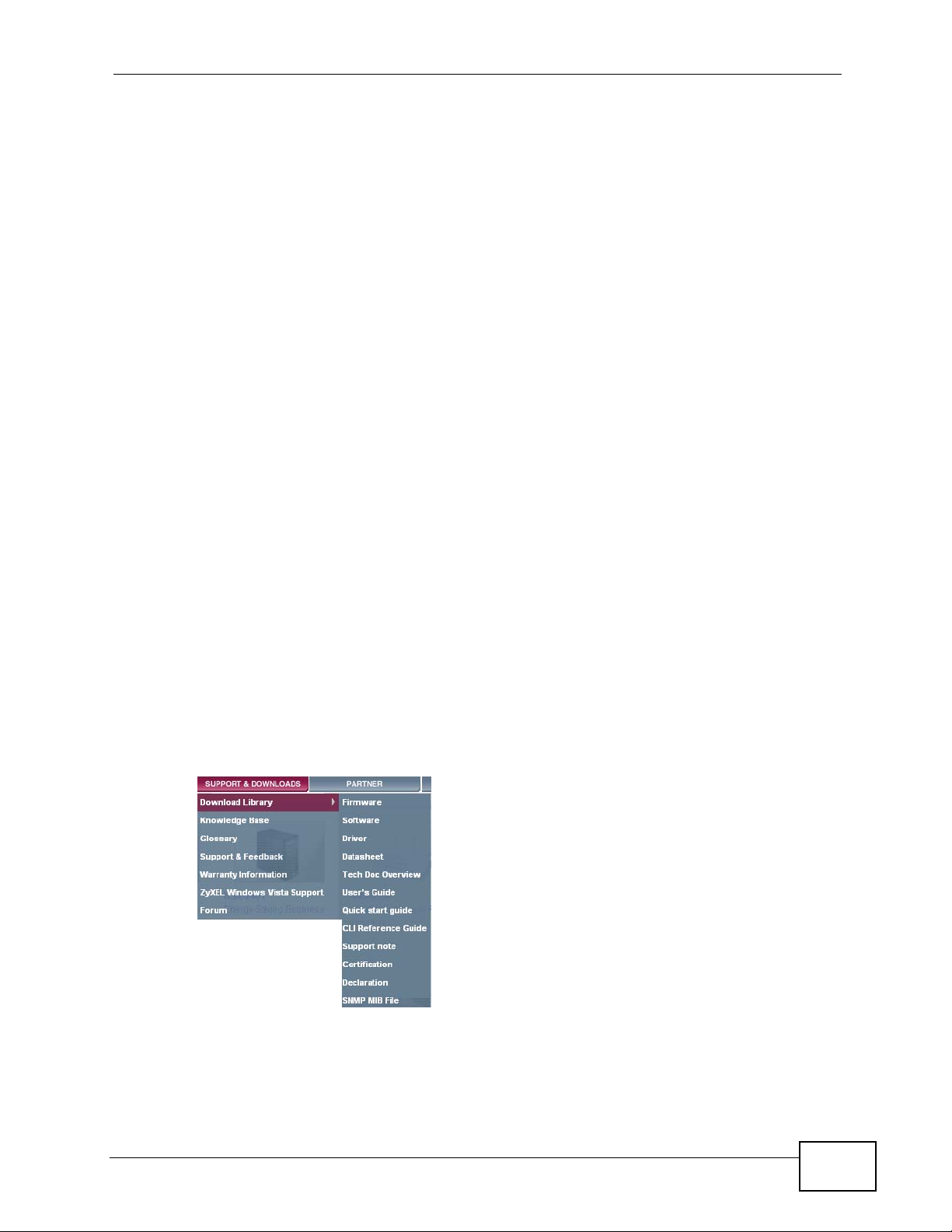
• Download Library
Search for the latest product updates and documentation from this link. Read
the Tech Doc Overview to find out how to efficiently use the documentation in
order to better understand how to use your product.
IES-1248-51V User’s Guide
3
Page 4

About This User's Guide
• Knowledge Base
If you have a specific question about your product, the answer may be here.
This is a collection of answers to previously asked questions about ZyXEL
products.
•Forum
This contains discussions on ZyXEL prod ucts. Learn from others who use ZyXEL
products and share your experiences as well.
Customer Support
Should problems arise that cannot be solved by the methods listed above, you
should conta ct your vendor. If you cannot contact your vendor, then contact a
ZyXEL office for the region in which you bought the device.
See http://www.zyxel.com/web/contact_us.php for contact information. Please
have the following informatio n ready when you contact an office.
• Product model and serial number.
•Warranty Information.
• Date that you received your device.
• Brief description of the problem and the steps you took to solve it.
4
IES-1248-51V User’s Guide
Page 5

Document Conventions
Document Conventions
Warnings and Notes
These are how warnings and notes are shown in this User’s Guide.
Warnings tell you about things that could harm you or your IES1248-51V.
Note: Notes tell you other important information (for example, other things you may
need to configure or helpful tips) or recommendations.
Syntax Conventions
• The IES-1248-51V may be referred to as the “IES-1248-51V”, the “device”, the
“system” or the “product” in this User’s Guide.
• Product labels, screen names, field labels and field choices are all in bold font.
• A key stroke is denoted by square brackets and uppercase text, for example,
[ENTER] means the “enter” or “ret urn” key on your keyboard.
• “Enter” means for you to type on e or more characters and then press the
[ENTER] key. “Select” or “choose” means for you to use one of the predefined
choices.
• A right angle bracket ( > ) within a screen name denotes a mouse click. For
example, Maintenance > Log > Log Setting means you first click
Maintenance in the navigation panel, then the Log sub menu and finally the
Log Setting tab to get to that screen.
• Units of measurement may denote the “metric” value or the “scientific” value.
For example, “k” for kilo may denote “1000” or “1024”, “M” for mega may
denote “1000000” or “1048576” and so on.
• “e.g.,” is a shorthand for “for instance”, and “i.e.,” means “that is” or “in other
words”.
IES-1248-51V User’s Guide
5
Page 6
Document Conventions
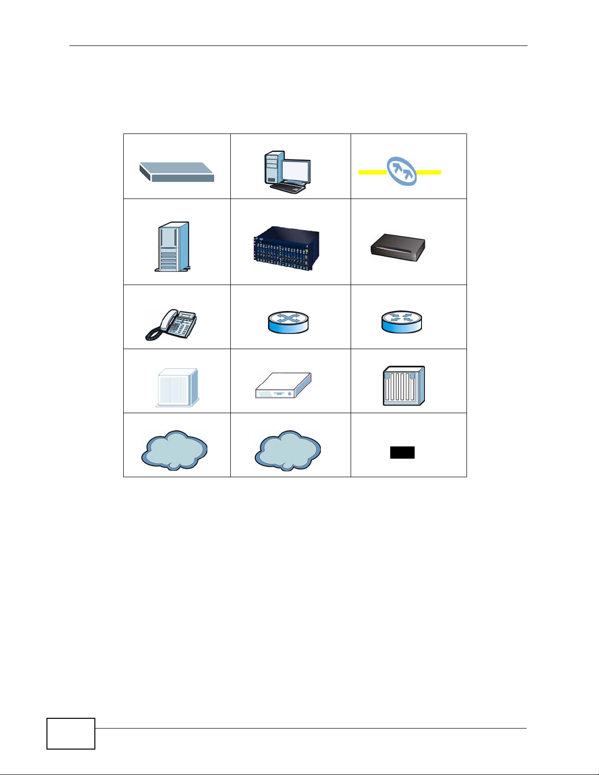
Icons Used in Figures
Figures in this User’s Guide may use the following generic icons. The IES-124851V icon is not an exact representation of your IES-1248-51V.
IES-1248-51V Computer Fiber Connection
Server OLT ADSL CPE
Telephone Switch Router
MDF Splliter Trunking Gateway
Internet A Network Optical Splitter
Internet
6
IES-1248-51V User’s Guide
Page 7

Safety Warnings
Safety Warnings
• Do NOT use this product near water, for example, in a wet basement or near a swimming
pool.
• Do NOT expose your device to dampness, dust or corrosive liquids.
• Do NOT store things on the device.
• Do NOT install, use, or service this device during a thunderstorm. There is a remote risk
of electric shock from lightning.
• Connect ONLY suitable accessories to the device.
• ONLY qualified service personnel should service or disassemble this device.
• Make sure to connect the cables to the correct ports.
• Place connecting cables carefully so that no one will step on them or stumble over them.
• Always disconnect all cables from this device before servicing or disassembling.
• Use ONLY power wires of the appropriate wire gauge (see Chapter 71 on page 579 for
details) for your device. Connect it to a power supply of the correct voltage (see Chapter
71 on page 579 for details). .
• Do NOT allow anything to rest on the power adaptor or cord and do NOT place the
product where anyone can walk on the power adaptor or cord.
• Do NOT use the device if the power adaptor or cord is damaged as it might cause
electrocution.
• If the power adaptor or cord is damaged, remove it from the device and the power
source.
• Do NOT attempt to repair the power adaptor or cord. Contact your local vendor to order a
new one.
• Do not use the device outside, and make sure all the connections are indoors. There is a
remote risk of electric shock from lightning.
• Do NOT obstruct the device ventilation slots, as insufficient airflow may harm your
device.
• Ensure that the fan filter is in place before switching on the IES-1248-51V.
• Use only No. 26 AWG (American Wire Gauge) or larger telecommunication line cord.
• Fuse Warning! Replace a fuse only with a fuse of the same type and rating.
• Fan Module Warning! Use the fan module handle when pulling out or pushing in the fan
module. Be careful not to put fingers or objects inside the fan module.
• Warnings for the optical transceivers:
PRODUCT COMPLIES WITH 21 CFR 1040.10 AND 1040.11
PRODUIT CONFORME SELON 21CFR 1040.10 ET 1040.11
CLASS 1 LASER PRODUCT APPAREIL À LASER DE CLASSE 1
This product is recyclable. Dispose of it properly.
IES-1248-51V User’s Guide
7
Page 8

Safety Warnings
8
IES-1248-51V User’s Guide
Page 9

Contents Overview
Contents Overview
Introduction ............................................................................................................................33
Introducing the IES-1248-51V ...................................................................................................35
Hardware Installation .......................................... .......................................................... .............47
Front Panel Connections ........................................................................................................... 53
MDF Connections ...................................................................................................................... 61
Power Connections ................................................................................................................... 65
Fan Maintenance ....................................................................................................................... 67
Basic Settings ........................................................................................................................69
Introducing the Web Configurator .............................................................................................. 71
Tutorials ..................................................................................................................................... 79
Home and Port Statistics Screens ............................................................................................. 89
System Information ......... .... ... ............................................. ... .... ... ... ... ... .... ... ... ... ....................... 97
General Setup ............................................. .... ... ... ... .... ... ... ... .... .............................................. 101
User Account ...................................... ... ... ............................................. .... ... ... ... .... ... ..............103
Switch Setup ............. ... ... .... ... ............................................. ... .... ... ... ... ... .................................. 107
IP Setup .......................... .... ... ... ... .... ... ... ... ............................................. .... ... ... ... .... ... ...............113
ENET Port Setup ......................................................................................................................117
xDSL Port Setup .......................................................................................................................119
xDSL Profiles Setup ................................................................................................................ 139
xDSL Line Data ....................................................................................................................... 151
Advanced Application .........................................................................................................161
VLAN ....................................................................................................................................... 163
IGMP .......................................................................................................................................171
Static Multicast ......................................................................................................................... 187
Multicast VLAN ........................................................................................................................ 189
Packet Filtering ........................................................................................................................ 195
MAC Filter ................................................................................................................................ 199
Spanning Tree Protocol ......................... .................................................................................. 201
Port Authentication ...... ... .... ... ..................................................................................................209
Port Security .................................... ... ... ... ............................................. .... ... ... ... .... ... ..............215
DHCP Relay ............................................................................................................................ 217
DHCP Snoop ........................................................................................................................... 223
2684 Routed Mode ...... ... .... ... ... ... .... ... ... ... ... .... ................................................ ... .... ... ... ... ... ..... 229
PPPoA to PPPoE .................................................................................................................... 237
DSCP .............................. .................... ................... .................... ................... ........................... 243
IES-1248-51V User’s Guide
9
Page 10

Contents Overview
TLS PVC ................... ... ............................................. .... ... ... ... .... ... ........................................... 247
ACL ..................................... ................... ................... .................... ................... ........................ 251
Downstream Broadcast ...........................................................................................................259
Syslog ....................................... .................................................... ........................................... 261
Access Control ........................................................................................................................ 263
IP Bridge ................................ ... ... .... ... ... ... ............................................. .... ... ... ... .... ... ..............273
PPPoE Intermediate Agent ...................................................................................................... 295
Maximum MTU Size ................................................................................................................ 299
PVC Upstream Limit ................................. ... .... ... ... ... .... ... ........................................................301
OUI Filter .................................................................................................................................303
Routing Protocol, Alarm, VoIP and Management .............................................................305
Static Routing ..........................................................................................................................307
Alarm .......................................................................................................................................309
VoIP ......................................................................................................................................... 317
Maintenance ............................................................................................................................ 343
Diagnostic .................................... ....................................................... ..................................... 347
MAC Table ............................................................................................................................... 355
ARP Ta ble .............................. ... ... .... ............................................. ... ... ... .... ... ... ... ..................... 359
Commands, Troubleshooting and Specifications ............................................................361
How to Access and Use the CLI .............................................................................................. 363
Common Commands ................ ... .... ... ... ... ................................................. ... ... ... .....................369
System Commands .................................................................................................................377
Alarm Commands .................................................................................................................... 385
DHCP Commands ................................................................................................................... 393
OUI Filter .................................................................................................................................405
IEEE 802.1Q Tagged VLAN and Isolation Commands ............................................................ 409
MAC Commands ..................................................................................................................... 419
IGMP Commands .................................................................................................................... 425
Packet Filter Commands .........................................................................................................437
Switch and Statistics Commands ............................................................................................ 441
IP Commands .............................. .... ... ... ... ... .... ... ... ... ...............................................................447
IP Bridge Commands ............................................... .... ... ... ... .... ... ... ... ... .... ... ... ... .....................451
SNMP Commands ................................................................................................................... 467
ADSL Commands .................................................................................................................... 469
G.B ond ................................................... .................................................... ...............................511
Virtual Channel Commands .....................................................................................................515
ACL Commands ...................................................................................................................... 535
VoIP Commands ...................................................................................................................... 541
Firmware and Configuration File Maintenance ........................................................................561
Troubleshooting ..................................................... .................................................................. 567
Product Specifications ............................................................................................................. 579
10
IES-1248-51V User’s Guide
Page 11

Contents Overview
Appendices and Index .........................................................................................................593
IES-1248-51V User’s Guide
11
Page 12

Contents Overview
12
IES-1248-51V User’s Guide
Page 13

Table of Contents
Table of Contents
About This User's Guide..........................................................................................................3
Document Conventions............................................................................................................5
Safety Warnings ........................................................................................................................7
Contents Overview ...................................................................................................................9
Table of Contents....................................................................................................................13
Part I: Introduction................................................................................. 33
Chapter 1
Introducing the IES-1248-51V................................................................................................35
1.1 Overview ............. ............................................. ... .... ... ... ... .... ................................................ 35
1.1.1 Voice Features .... ... ... ............................................. .... ... ... ... ... .... ... .............................35
1.2 MDU Application ........................... ... ... ... .... ... ... ... ................................................................. 36
1.3 System Description ... .... ... ... ... .... ... ... ... ............................................. .... ... ... ... .... ... ................ 37
1.4 VoIP Features ........... .... ... ... ... .... ............................................. ... ... ... .... ... ... .......................... 41
1.5 Technical Reference ............................................................................................................ 45
Chapter 2
Hardware Installation..............................................................................................................47
2.1 General Installation Instructions ................................................................... .... ... ................47
2.2 Dust Filter Installation .......................................................................................................... 47
2.3 Installation Scenarios ............................................. ... ... ... .... ... ... ... ... .... ... ... .......................... 49
2.3.1 Desktop Installation Procedure .................................................................................. 49
2.3.2 Rack-Mounted Installation .......................................................................................... 50
Chapter 3
Front Panel Connections .......................................................................................................53
3.1 Front Panel ...................................... ... ... .............................................. ... ... ... .... ... ... .............53
3.1.1 Front Panel Ports ................ ... ............................................. ... .... ... ... ... .... ................... 53
3.1.2 Front Panel LEDs .......................................... ............................................................. 54
3.2 1000/100M Auto-Sensing Ethernet .............................................. ... .... ... ... ... .... ... ... ... ... .......55
3.2.1 Ethernet Default Settings ....... ... ................................................................................. 55
3.3 SFP Mini GBIC Slots .............................................................................................. ... ... ....... 55
3.3.1 Transceiver Installation ............................................................................................. 56
IES-1248-51V User’s Guide
13
Page 14

Table of Contents
3.3.2 Transceiver Removal ................................................................................................. 57
3.4 Console Port Connection .....................................................................................................58
3.5 ALARM Connections ....................................................................... .... ... ............................. 58
3.6 ADSL Connections .......... ... ... ................................................. ... ... ....................................... 58
Chapter 4
MDF Connections ...................................................................................................................61
4.1 MDF Connections Overview .................. .... ... ... ... ................................................................. 61
4.2 MDF (Main Distribution Frame) . ... ... ... ... .... .......................................................................... 62
4.3 Telco-50 Cables ............................................... ... .... ... ... ... .... ................................................62
Chapter 5
Power Connections ................................................................................................................65
5.1 Power Connections Overview ............................................................................................. 65
5.2 Power Connection ........ ... ... ... ................................................. ... ... ....................................... 65
Chapter 6
Fan Maintenance.....................................................................................................................67
6.1 Fan Maintenance Introduction ............................................................................................. 67
6.2 Removing and Installing the Fan Module ............................................................................ 67
Part II: Basic Settings............................................................................ 69
Chapter 7
Introducing the Web Configurator ........................................................................................71
7.1 Web Configurator Overview ................................................................................................. 71
7.2 Screen Privilege Levels ................................ ... ... .... ............................................................. 71
7.3 Accessing the Web Configurator ......................................................................................... 71
7.4 Navigation Panel ................................................................................................................. 73
7.5 Changing Your Password .......................... ... ... ... .... ... ... ... .... ... ............................................. 76
7.6 Saving Your Configuration ................................................................................................... 77
7.7 Logging Out of the Web Configurator ..................................... ............................................. 77
Chapter 8
Tutorials...................................................................................................................................79
8.1 Initial Configuration Overview ............. ... .... ............................................. ... ... .... ... ... ... ..........79
8.2 Initial Configuration ....................... ... ... ... .... ... ... ............................................. .... ... ... ... ..........79
8.3 H.248 Configuration Example ..............................................................................................85
Chapter 9
Home and Port Statistics Screens.........................................................................................89
14
IES-1248-51V User’s Guide
Page 15

Table of Contents
9.1 Home Screen ................ ............................................. ... ... .... ... ... ... ....................................... 89
9.1.1 Ethernet Port Statistics Screen ........ ... ... ... .... ... ... ... .... ... ... ... ... .................................... 91
9.1.2 ADSL Port Statistics Screen ....................................................................................... 94
Chapter 10
System Information ................................................................................................................97
Chapter 11
General Setup........................................................................................................................101
Chapter 12
User Account.........................................................................................................................103
12.1 User Account Screen .......................................................................................................103
12.2 Authentication Screen .....................................................................................................105
Chapter 13
Switch Setup .........................................................................................................................107
13.1 GARP Timer Setup ..........................................................................................................107
13.2 Switch Modes .................................................................................................................. 107
13.2.1 Standalone Switch Mode ........................................................................................ 107
13.2.2 Port Isolation with Standalone Switch Mode Example ................................... ... .... . 108
13.2.3 Daisychain Switch Mode ........................................................................................ 108
13.2.4 Port Isolation with Daisychain Switch Mode Example ............................................ 109
13.3 Switch Setup Screen ........................................................................................................110
Chapter 14
IP Setup..................................................................................................................................113
Chapter 15
ENET Port Setup...................................................................................................................117
Chapter 16
xDSL Port Setup....................................................................................................................119
16.1 ADSL Standards Overview ...............................................................................................119
16.2 Downstream and Upstream ..............................................................................................119
16.3 Profiles ..............................................................................................................................119
16.4 Interleave Delay ...............................................................................................................120
16.4.1 Fast Mode ..............................................................................................................120
16.5 Configured Versus Actual Rate ....................................................................................... 120
16.6 Default Settings ............................................................................................................... 121
16.7 xDSL Port Setup Screen ................................................................................................. 121
16.7.1 xDSL Port Setting Screen ...................................................................................... 124
16.8 Virtual Channels .............................................................................................................. 128
16.8.1 Super Channel ....................................................................................................... 128
16.8.2 LLC .........................................................................................................................128
IES-1248-51V User’s Guide
15
Page 16

Table of Contents
16.8.3 VC Mux ..................................................................................................................128
16.8.4 Virtual Channel Profile ........................................................................................... 129
16.9 VC Setup Screen ............................................................................................................. 129
16.10 Priority-based PVCs ......................................................................................................133
16.11 PPVC Setup Screen ....... ...............................................................................................134
16.11.1 PPVC Setup Members Screen ............................................................................. 136
Chapter 17
xDSL Profiles Setup..............................................................................................................139
17.1 Port Profile Screen .......................................................................................................... 139
17.2 ATM QoS .........................................................................................................................142
17.3 Traffic Shaping ................................................................................................................. 142
17.3.1 ATM Traffic Classes ............................................................................................... 142
17.3.2 Traffic Parameters .................................................................................................. 143
17.4 Upstream Policing ........................................................................................................... 145
17.5 VC Profile Screen ............................................................................................................ 146
17.6 Alarm Profile Screen ........................................................................................................ 148
Chapter 18
xDSL Line Data......................................................................................................................151
18.1 xDSL Line Rate Info Screen ............................................................................................ 151
18.2 xDSL Line Data Screen ................................................................................................... 153
18.3 xDSL Performance Screen .............................................................................................. 155
18.4 G.Bond Screen ................................................................................................................158
Part III: Advanced Application............................................................ 161
Chapter 19
VLAN......................................................................................................................................163
19.1 Introduction to VLANs ......................................................................................................163
19.2 Introduction to IEEE 802.1Q Tagged VLAN ..................................................................... 163
19.2.1 Forwarding Tagged and Untagged Frames ....................... ... .... ... ... ........................ 164
19.3 VLAN Status Screen ........................................................................................................165
19.4 Static VLAN Setting Screen ........................................................ ..................................... 167
19.5 VLAN Port Setting Screen ....................................... ... ... .... ... ... ... ... .... ... ... ... ..................... 169
Chapter 20
IGMP.......................................................................................................................................171
20.1 IGMP ............................................................................................................................... 171
20.2 IP Multicast Addresses ....................................................................................................171
20.2.1 IGMP Snooping ...................................................................................................... 171
16
IES-1248-51V User’s Guide
Page 17

Table of Contents
20.2.2 IGMP Proxy ............................................................................................................ 172
20.3 IGMP Status Screen ........................................................................................................174
20.4 IGMP Bandwidth Screen ................................................................................................. 176
20.5 Bandwidth Port Setup Screen ......................................................................................... 177
20.6 Config Screen .................................................................................................................. 179
20.7 IGMP Filter Screen .......................................................................................................... 180
20.8 IGMP Port Group Screen ................................................................................................ 182
20.9 IGMP Port Info Screen .................................................................................................... 183
20.10 IGMP Count Screen ...................................................................................................... 184
Chapter 21
Static Multicast......................................................................................................................187
21.1 Static Multicast ................................................................................................................. 187
21.2 Static Multicast Screen .................................................................................................... 187
Chapter 22
Multicast VLAN......................................................................................................................189
22.1 Multicast VLAN Overview ................................................................................................ 189
22.2 MVLAN Status Screen .....................................................................................................190
22.3 MVLAN Setup Screen ..................................................................................................... 191
22.4 MVLAN Group Screen ..................................................................................................... 193
Chapter 23
Packet Filtering.....................................................................................................................195
23.1 Packet Filter Screen ........................................................................................................ 195
Chapter 24
MAC Filter..............................................................................................................................199
24.1 MAC Filter Introduction .................................................................................................... 199
24.2 MAC Filter Screen ........................................................................................................... 199
Chapter 25
Spanning Tree Protocol........................................................................................................201
25.1 RSTP and STP ................................................................................................................ 201
25.2 Spanning Tree Protocol Status Screen ............................................................................204
25.3 Spanning Tree Protocol Screen .......................................................................................206
Chapter 26
Port Authentication...............................................................................................................209
26.1 Introduction to Authentication .......................................................................................... 209
26.1.1 RADIUS ..................................................................................................................209
26.1.2 Introduction to Local User Database ...................................................................... 209
26.2 RADIUS Screen ...............................................................................................................210
IES-1248-51V User’s Guide
17
Page 18

Table of Contents
26.3 802.1x Screen ................................................................................................................. 212
Chapter 27
Port Security..........................................................................................................................215
27.1 Port Security Overview ....................................................................................................215
27.2 Port Security Screen ................................ ...................... ....................... ...................... ..... 215
Chapter 28
DHCP Relay...........................................................................................................................217
28.1 DHCP Relay .................................................................................................................... 217
28.2 DHCP Relay Agent Information Option (Option 82) ........................................................217
28.2.1 Private Format ........................................................................................................ 217
28.2.2 TR-101 Format ....................................................................................................... 218
28.3 DHCP Relay Screen ............................ .... ... ... ... .... ... ... ... .... ... ... ... ... .... ... ........................... 219
Chapter 29
DHCP Snoop..........................................................................................................................223
29.1 DHCP Snoop Overview ................................................................................................... 223
29.2 DHCP Snoop Screen ....................................................................................................... 224
29.3 DHCP Snoop Status Screen ............................................................................................ 225
29.4 DHCP Counter Screen .................................................................................................... 227
Chapter 30
2684 Routed Mode................................................................................................................229
30.1 2684 Routed Mode ..........................................................................................................229
30.1.1 2684 Routed Mode Example ............................. ............. ............. ............. ............. . 229
30.2 2684 Routed PVC Screen ............................................................................................... 230
30.3 2684 Routed Domain Screen .......................................................................................... 232
30.4 RPVC Arp Proxy Screen ................................................................................................. 234
30.5 2684 Routed Gateway Screen ........................................................................................ 235
Chapter 31
PPPoA to PPPoE...................................................................................................................237
31.1 PPPoA to PPPoE Overview ............................................................................................ 237
31.2 PPPoA to PPPoE Screen ................................................................................................ 238
31.3 PPPoA to PPPoE Status Screen .....................................................................................241
Chapter 32
DSCP......................................................................................................................................243
32.1 DSCP Overview ............................................................................................................... 243
32.2 DSCP Setup Screen ........................................................................................................ 243
32.3 DSCP Map Screen .......................................................................................................... 244
18
IES-1248-51V User’s Guide
Page 19

Table of Contents
Chapter 33
TLS PVC .................................................................................................................................247
33.1 Transparent LAN Service (TLS) Overview ......................................................................247
33.1.1 TLS Network Example ........................................................................................... 248
33.2 TLS PVC Screen .............................................................................................................248
Chapter 34
ACL.........................................................................................................................................251
34.1 Access Control List (ACL) Overview ............................................................................... 251
34.1.1 ACL Profile Rules ................................................................................................... 251
34.1.2 ACL Profile Actions ................................................................................................252
34.2 ACL Setup Screen ........................................................................................................... 253
34.3 ACL Profile Screen .......................................................................................................... 255
34.4 ACL Profile Map Screen .................................................................................................. 257
Chapter 35
Downstream Broadcast........................................................................................................259
35.1 Downstream Broadcast ................................................................................................... 259
35.2 Downstream Broadcast Screen ....................................................................................... 259
Chapter 36
Syslog....................................................................................................................................261
36.1 Syslog ..............................................................................................................................261
36.2 SysLog Screen ................................................................................................................ 261
Chapter 37
Access Control......................................................................................................................263
37.1 Access Control Screen ..................................... .... ... ... ... .... ... ... ... ..................................... 263
37.2 Access Control Overview ........................................................................................... .... . 263
37.3 SNMP ..............................................................................................................................264
37.3.1 Supported MIBs ..................................................................................................... 265
37.3.2 SNMP Traps ........................................................................................................... 266
37.4 SNMP Screen .................................................................................................................. 268
37.5 Service Access Control Screen ....................................................................................... 269
37.6 Remote Management Screen .......................................................................................... 270
Chapter 38
IP Bridge................................................................................................................................273
38.1 IP Bridge Overview .......................................................................................................... 273
38.1.1 Upstream and Downstream Traffic ......................................................................... 274
38.1.2 IP Bridge Settings .................................................................................................. 275
38.1.3 IP Bridge Configuration ..................... ..................................................................... 277
38.2 IPB PVC Screen .............................................................................................................. 278
IES-1248-51V User’s Guide
19
Page 20

Table of Contents
38.3 IPB Domain Screen .........................................................................................................280
38.3.1 Configure IPB Domain Screen ............................................................................... 282
38.4 IPB Edge Router Screen ................................................................................................. 284
38.5 IPB Downlink Interface Screen ................ ... ... ... .............................................. ... ... ... ... .... . 285
38.5.1 Current Interfaces Screen ...................................................................................... 288
38.6 IPB Routing Table Screen ............................................................................................... 289
38.6.1 Current Routes Screen .......................................................................................... 291
38.7 IPB ARP Proxy Screen .................................................................................................... 293
Chapter 39
PPPoE Intermediate Agent...................................................................................................295
39.1 PPPoE Intermediate Agent Tag Formate ........................................................................ 295
39.2 PPPoE Intermediate Agent Screen ................................................................................. 297
Chapter 40
Maximum MTU Size ..............................................................................................................299
40.1 Maximum MTU Size Screen ............................................................................................ 299
Chapter 41
PVC Upstream Limit..............................................................................................................301
41.1 PVC Upstream Limit Screen ............................................................................................ 301
Chapter 42
OUI Filter................................................................................................................................303
42.1 OUI Filter Screen ........................ ................................................... .................................. 303
Part IV: Routing Protocol, Alarm, VoIP and Management................ 305
Chapter 43
Static Routing........................................................................................................................307
Chapter 44
Alarm......................................................................................................................................309
44.1 Alarm ............................................................................................................................... 309
44.2 Alarm Status Screen ................... ... ... ... .... ................................................ ... .... ... ... ... ... ..... 309
44.3 Alarm Descriptions .......................................................................................................... 310
44.4 Alarm Event Setup Screen .............................................................................................. 313
44.4.1 Edit Alarm Event Setup Screen .............................................................................. 314
44.5 Alarm Port Setup Screen ................................................................................................. 316
Chapter 45
VoIP........................................................................................................................................317
20
IES-1248-51V User’s Guide
Page 21

Table of Contents
45.1 VoIP Overview ................................................................................................................. 317
45.1.1 Introduction to H.248 .............................................................................................. 317
45.1.2 Termination .............................................................................................................318
45.1.3 H.248 Commands .................................................................................................. 319
45.1.4 H.248/MEGACO Call Progression Example ......................................................... 319
45.1.5 RTP ........................................................................................................................ 321
45.1.6 Voice Coding .......................................................................................................... 321
45.1.7 PSTN Call Setup Signaling .................................................................................... 322
45.1.8 VoIP and VoiceBand Data (VBD) ........................................................................... 323
45.2 VoIP Port Setup Screens ................................................................................................. 323
45.2.1 Port View Screen ................................................................................................... 324
45.2.2 Port Edit Screen ..................................................................................................... 326
45.2.3 General Screen ......................................................................................................328
45.3 H.248 Profile Screen ....................................................................................................... 331
45.4 DSP Profile Screen ..........................................................................................................333
45.5 Media Gateway Screen ................................................................................................... 335
45.6 VoIP Line Status and Info Screen .................................................................................... 336
45.7 Diagnostic Screens ........................ ................... ....................... ....................... ................. 339
45.7.1 MLT Test Screen .................................................................................................... 339
45.7.2 MLT Relay .............................................................................................................. 342
Chapter 46
Maintenance..........................................................................................................................343
46.1 Maintenance Screen ........................................................................................................343
46.2 Firmware Upgrade Screen ............................................ .... ... ... ... ... .... ... ... ... .... ... ... ........... 3 43
46.3 Restore Configuration Screen ......................................................................................... 344
46.4 Backing Up a Configuration File ...................................................................................... 345
46.5 Load Factory Defaults .....................................................................................................345
46.6 Reboot System ................................................................................................................ 346
46.7 Command Line FTP ........................................................................................................ 346
Chapter 47
Diagnostic..............................................................................................................................347
47.1 Diagnostic Screen ........................................................................................................... 347
47.2 Log Format ...................................................................................................................... 350
47.2.1 Log Messages ........................................................................................................ 350
47.3 LDM Test Parameters ......................................................................................................352
47.4 ToneDiag Parameters ......................................................................................................353
Chapter 48
MAC Table..............................................................................................................................355
48.1 Introduction to MAC Table ............................................................................................... 355
48.2 MAC Table Screen ........................................................................................................... 356
IES-1248-51V User’s Guide
21
Page 22

Table of Contents
Chapter 49
ARP Table..............................................................................................................................359
49.1 Introduction to ARP Table ................................................................................................359
49.1.1 How ARP Works ......................................................... ... ... ... .... ... ... ........................ 359
49.2 ARP Table Screen ........................................................................................................... 360
Part V: Commands, Troubleshooting and Specifications................ 361
Chapter 50
How to Access and Use the CLI..........................................................................................363
50.1 Accessing the CLI ................ .... ........................................................................................ 363
50.1.1 Console Port .......................................................................................................... 363
50.1.2 Telnet ...................................................................................................................... 363
50.1.3 SSH ........................................................................................................................ 364
50.2 Logging in ........................................................................................................................ 364
50.3 Command Conventions ................................................................................................... 365
50.4 Using Shortcuts and Getting Help ................................................................................... 367
50.5 Command Privilege Levels .............................................................................................. 367
50.6 Saving Your Configuration ............................................................................................... 368
50.7 Logging Out ..................................................................................................................... 368
Chapter 51
Common Commands............................................................................................................369
51.1 Port Selection .................................................................................................................. 369
51.2 IP Status .......................................................................................................................... 370
51.3 Configuration Status ........................................................................................................ 371
51.4 Reset to Defaults ............................................................................................................. 371
51.5 Port and VLAN Isolation ..................................................................................................372
51.5.1 Isolation Show Command ...................................................................................... 372
51.5.2 Port Isolation Enable Command ............................................................................ 372
51.5.3 Port Isolation Disable Command ............................................................................ 373
51.5.4 VLAN Isolation Set Command ............................................................................... 373
51.5.5 VLAN Isolation Delete Command .......................................................................... 373
51.6 Statistics Monitor Command ............................................................................................374
51.7 Statistics Port Command ................................................................................................. 375
Chapter 52
System Commands...............................................................................................................377
52.1 System Commands ......................................................................................................... 377
52.1.1 Idle Timeout Set Command Example ..................................................................... 379
52.1.2 Basic System Information Command Examples .................................................... 380
22
IES-1248-51V User’s Guide
Page 23

Table of Contents
52.1.3 Logs Command Examples ............................. ........................................................ 381
52.1.4 Clearing the Log ............................................................................. ... .... ... .............. 384
Chapter 53
Alarm Commands.................................................................................................................385
53.1 General Alarm Command Parameters ............................................................................385
53.2 Alarm Commands ............................................................................................................386
53.2.1 Alarm Show Command Example ........................................................................... 387
53.2.2 Alarm Port Show Command Example .................................................................... 388
53.2.3 Alarm Port Set Command Example ....................................................................... 389
53.2.4 Alarm Tablelist Command Example .......................................................................389
53.2.5 Log Format ............................................................................................................. 389
53.2.6 Alarm History Show Command Example ............................................................... 390
53.2.7 Alarm History Clear Command Example ............................................................... 390
53.2.8 Alarm XEdit Command Example ............................................................................ 391
Chapter 54
DHCP Commands.................................................................................................................393
54.1 General DHCP Command Parameters ........................................................................... 393
54.2 DHCP Relay Commands ................................................................................................. 393
54.2.1 Show Command Example ...................................................................................... 395
54.3 DHCP Relay Option 82 Sub-option 1 Commands ................ ........................................... 396
54.4 DHCP Relay Option 82 Sub-option 2 Commands ................ ........................................... 396
54.5 PPPoE Intermediate Agent Information Commands ....................................................... 397
54.5.1 PPPoE Intermediate Agent Enable Command Example ....................................... 398
54.5.2 PPPoE Intermediate Agent Info Command Example ............................................. 399
54.5.3 PPPoE Intermediate Agent Set Command Example ............................................. 399
54.5.4 PPPoE Intermediate Agent Show Command Example .......................................... 399
54.6 DHCP Snoop Commands ................................................................................................400
54.6.1 DHCP Snoop Enable Command Example ............................................................. 401
54.6.2 DHCP Snoop Set Static IP Command Example .................................................... 401
54.6.3 DHCP Snoop Delete Static IP Command Example ............................................... 402
54.6.4 DHCP Snoop Show Command Example ............................................................... 402
54.6.5 DHCP Counter Statistics Command Example ....................................................... 402
54.6.6 DHCP Snoop Statistics Command Example .................................................. ........403
Chapter 55
OUI Filter................................................................................................................................405
55.1 OUI Filtering .................................................................................................................... 405
55.1.1 OUI Set and Delete Command Examples ......................... ............. ............. ........... 406
55.1.2 OUI Enable and Disable Command Examples ...................................................... 406
55.1.3 OUI Mode Command Example .............................................................................. 407
55.1.4 OUI Show Command Example .............................................................................. 407
IES-1248-51V User’s Guide
23
Page 24

Table of Contents
Chapter 56
IEEE 802.1Q Tagged VLAN and Isolation Commands.......................................................409
56.1 IEEE 802.1Q Tagging Types ........................................................................................... 409
56.2 Filtering Databases .......................................................................................................... 409
56.2.1 Static Entries (SVLAN Table) ................................................................................. 410
56.3 IEEE VLAN1Q Tagged VLAN Configuration Commands ...............................................410
56.3.1 VLAN Port Show Command Example ....................................................................412
56.3.2 VLAN PVID Command Example .......................................... .................................. 412
56.3.3 VLAN Priority Command Example ....... ... .... ... ... ... .... .............................................. 412
56.3.4 VLAN Set Command Examples ............................................................................. 413
56.3.5 VLAN Frame Type Command Example ................................................................. 414
56.3.6 VLAN CPU Show Command Example ...................................................................414
56.3.7 VLAN CPU Set Command Example ......................................................................414
56.3.8 Configuring Management VLAN Example .................................................. ... ... .....414
56.3.9 VLAN Delete Command Example ............................... ........................................... 415
56.3.10 VLAN Show Command Example ......................................................................... 415
56.4 VLAN Statistics Commands ............................................................................................ 415
56.5 GARP Timer Commands ................................................................................................ 416
56.6 Isolation Commands .......................................................................................................416
Chapter 57
MAC Commands...................................................................................................................419
57.1 MAC Filter Commands .................................................................................................... 419
57.1.1 MAC Filter Show Command Example .................................................................... 420
57.1.2 MAC Filter Enable Command Example ................................................................. 420
57.1.3 MAC Filter Disable Command Example ................................................................ 420
57.1.4 MAC Filter Mode Command Example .................................................................... 420
57.1.5 MAC Filter Set Command Example .......................................................................420
57.1.6 MAC Filter Delete Command Example .................................................................. 421
57.2 MAC Count Commands ................................................................................................... 421
57.2.1 MAC Count Show Command Example .................................................................. 422
57.2.2 MAC Count Enable Command Example ................................................................ 422
57.2.3 MAC Count Disable Command Example ............................................................... 422
57.2.4 MAC Count Set Command Example .................... ............. ............. ............. ........... 422
57.3 MAC Anti-Spoofing Commands ....................................................................................... 422
Chapter 58
IGMP Commands..................................................................................................................425
58.1 IGMP Snooping Commands ............................................................................................ 425
58.1.1 IGMP Snoop Show Example .................................................................................. 425
58.1.2 IGMP Snoop Enable Example ............................................................................... 425
58.1.3 IGMP Snoop Disable Command Example .............................................................426
58.2 IGMP Filter Commands ................................................................................................... 426
24
IES-1248-51V User’s Guide
Page 25

Table of Contents
58.2.1 IGMP Filter Show Command Example .................................................................. 427
58.2.2 IGMP Filter Set Command Example ...................................................................... 427
58.2.3 IGMP Filter Profile Set Command Example ........................................................... 427
58.2.4 IGMP Filter Profile Delete Command Example ...................................................... 427
58.2.5 IGMP Filter Profile Show Command Example ....................................................... 428
58.3 IGMP Bandwidth Commands .......................................................................................... 428
58.4 IGMP Bandwidth Port Commands ................................................................................... 429
58.4.1 IGMP Bandwidth Port Show Command Example .................................................. 430
58.5 IGMP Count Limit Commands ......................................................................................... 430
58.5.1 IGMP Count Disable Command Example .............................................................. 430
58.5.2 IGMP Count Enable Command Example ...............................................................431
58.5.3 IGMP Count Set Command Example .................................................................... 431
58.5.4 IGMP Count Show Command Example ................................................................. 431
58.6 IGMP Snoop Statistics Commands ................................................................................. 431
58.6.1 IGMP Snoop Info Statistics Command Example .................................................... 432
58.6.2 IGMP Group Statistics Command Example ........................................................... 432
58.6.3 IGMP Port Info Statistics Command Example ...................................................... . 432
58.6.4 IGMP Port Group Statistics Command Example .............................................. .... . 432
58.7 IGMP Query VLAN Commands ............................ ...................................................... .....433
58.8 Multicast VLAN Commands ............................................................................................. 433
58.8.1 Multicast VLAN Disable Command Example ......................................................... 435
58.8.2 Multicast VLAN Show Command Example ............................................................ 435
58.8.3 Multicast VLAN Group Set Command Example .......................... ................ ........... 435
Chapter 59
Packet Filter Commands......................................................................................................437
59.1 Command Summary ........................................................................................................437
59.1.1 Packet Filter Show Command Example ................... ... ... ... ... .... ... ... ... .... ... ... ... ... .... . 438
59.1.2 Packet Filter Set Command Example ......... ... ... ... .... ... ... ... ... .... ... ... ... .... ... .............. 439
59.1.3 Packet Filter PPPoE Only Command Example ........................ ............. ............ ..... 439
Chapter 60
Switch and Statistics Commands........................................................................................441
60.1 IEEE 802.1x Commands ................................................................................................. 441
60.2 DSCP Commands ........................................................................................................... 442
60.3 Ethernet Commands ........................................................................................................442
60.4 Queuemap Commands ................................................................................................... 443
60.5 RSTP Commands ............................................................................................................ 443
60.6 Static Multicast Commands ............................................................................................. 444
60.7 RMON Command ............................................................................................................ 445
Chapter 61
IP Commands........................................................................................................................447
IES-1248-51V User’s Guide
25
Page 26

Table of Contents
61.1 General IP Commands .................................................................................................... 447
61.1.1 IP Settings and Default Gateway Example ............................................................ 449
61.1.2 Route Show Command Example ........................................................................... 449
61.1.3 ARP Show Command Example ............................................................................. 449
61.2 Statistics IP Command Example .....................................................................................450
Chapter 62
IP Bridge Commands............................................................................................................451
62.1 IP Bridge Command Input Values .................................................................................... 451
62.2 IP Bridge Domain Commands ......................................................................................... 452
62.2.1 IP Bridge Domain Show Command Example ........................................................ 454
62.2.2 IP Bridge Domain DHCP VLAN Enable Command Example ................................. 454
62.2.3 IP Bridge Domain VLAN Registration Command Example .................................... 455
62.3 IP Bridge Edge Router Commands ................................................................................. 455
62.3.1 IP Bridge Edge Router Set Command Example .................................................... 455
62.3.2 IP Bridge Edge Router Show Command Example ................... ... ... ... .... ... ... ........... 4 56
62.3.3 IP Bridge Edge Router Delete Command Example ............................................... 456
62.4 IP Bridge Routing Table Commands ............................................................................... 456
62.4.1 IP Bridge Route Set Command Example ...............................................................457
62.4.2 IP Bridge Route Show Command Example ........................................................... 458
62.4.3 IP Bridge Route Runtime Command Example ..................... .................................. 458
62.4.4 IP Bridge Route Delete Command Example .......................................................... 459
62.5 IP Bridge Downlink Interface Commands ...................... .... ... ... ... ... .... ... ... ... .... ... ... ... ... .....459
62.5.1 IP Bridge Downlink Interface Set Command Example ........................................... 460
62.5.2 IP Bridge Downlink Interface Show Command Example ....................................... 461
62.5.3 IP Bridge Downlink Interface Runtime Command Example .................. ................. 461
62.5.4 IP Bridge Downlink Interface Delete Command Example ................. ..................... 462
62.6 IP Bridge PVC Commands .............................................................................................. 462
62.6.1 IP Bridge PVC Show Command Example ............................................................. 463
62.6.2 IP Bridge PVC Set Command Example ................................................................. 463
62.6.3 IP Bridge PVC Delete Command Example ............................................................ 464
62.7 IP Bridge ARP Proxy Commands ...................................... .............................................. 464
62.7.1 IP Bridge ARP Proxy Agingtime Show Command Example .................................. 465
62.7.2 IP Bridge ARP Proxy Show Command Example . .... ... ... ... ... .... ... ... ... .... ... ... ... ... .... . 465
Chapter 63
SNMP Commands.................................................................................................................467
63.1 SNMP Commands ........................................................................................................... 467
Chapter 64
ADSL Commands..................................................................................................................469
64.1 ADSL Command Input Values ......................................................................................... 469
64.2 ADSL Commands ............................................................................................................ 470
26
IES-1248-51V User’s Guide
Page 27

Table of Contents
64.2.1 ADSL Show Command Example ........................................................................... 476
64.2.2 ADSL Name Command Example ........................................................................... 476
64.2.3 ADSL Tel Command Example ................................................................................477
64.2.4 ADSL Loopback Command Example .....................................................................477
64.2.5 ADSL Upstream PSD Command Example ............................................................ 477
64.2.6 ADSL Downstream PSD Command Example ................... ................ ................ ..... 477
64.2.7 ADSL Upstream Carrier Command Example ........................... ...................... ........ 477
64.2.8 ADSL Downstream Carrier0 Command Example ................................. ... ... ... ... .... . 478
64.2.9 ADSL Downstream Carrier1 Command Example ................................. ... ... ... ... .... . 479
64.2.10 PMM Parameters Command Example .................................................................479
64.2.11 Impulse Noise Protection Command Example ..................................................... 480
64.3 ADSL Profile Commands .................................................................................................481
64.3.1 ADSL Profile Show Command Example ................................................................ 484
64.3.2 ADSL Profile Set Command Example ....................................................................484
64.3.3 ADSL Profile Delete Command Example ...............................................................485
64.3.4 ADSL Profile Map Command Example .................................................................. 485
64.4 Statistics ADSL Commands ............................................................................................. 486
64.4.1 ADSL Show Command Example ........................................................................... 489
64.4.2 Linedata Command Example ................................................................................. 490
64.4.3 ADSL Lineinfo Command Example ........................................................................491
64.4.4 Lineperf Command Example ..................................................................................492
64.4.5 15 Minute Performance Command Example .........................................................493
64.4.6 1 Day Performance Command Example ................................................................495
64.4.7 Line Diagnostics Set Command Example ............................ .... ... ... ... .... ... ... ... ... .... . 495
64.4.8 Line Diagnostics Get Command Example ............................................................. 496
64.4.9 Line Diagnostics Get 992.3 Command Example ........................................... ... .... . 498
64.4.10 SELT Diagnostic Set Command Example ............................................................ 500
64.4.11 SELT Diagnostic Get Command Example ............................................................500
64.4.12 Tone Diagnostics 992.3 Command Example ............... ........................................ 501
64.5 Alarm Profile Commands ................................................................................................. 503
64.5.1 Alarm Profile Show Command Example ................................................................ 508
64.5.2 Alarm Profile Set Command Example ....................................................................508
64.5.3 Alarm Profile Delete Command Example ................................. ................ ............. . 508
64.5.4 Alarm Profile Map Command Example .................................................................. 509
64.5.5 Alarm Profile Showmap Command Example ......................................................... 509
Chapter 65
G.Bond ...................................................................................................................................511
65.1 ADSL Port Bonding ................................................. ... ... .... ... ... ... ... .... ... ............................511
65.1.1 G.Bond Set and Delete Command Examples ........................................................ 512
65.1.2 G.Bond Show Example ..........................................................................................512
65.1.3 Statistics ADSL G.Bond Command Example ......................................................... 512
IES-1248-51V User’s Guide
27
Page 28

Table of Contents
Chapter 66
Virtual Channel Commands.................................................................................................515
66.1 Virtual Channel Command Input Values .......................................................................... 515
66.2 Virtual Channel Profile Commands ....................................... ...... ... ....... ...... ....... ...... ....... . 516
66.2.1 Set Virtual Channel Profile Command .................................................................. 517
66.2.2 Delete Virtual Channel Profile Command ............................................................. 518
66.3 PVC Channels ................................................................................................................. 518
66.3.1 PVC Set Command ................................................................................................ 519
66.4 Priority-based PVCs ........................................................................................................ 519
66.4.1 PPVC Set Command Example .............................................................................. 520
66.4.2 PPVC Member Set Command Example ................................................................ 520
66.4.3 PPVC Member Delete Command Example ........................................................... 521
66.4.4 PPVC Member Show Command Example .............................................................521
66.4.5 PPVC Show Command Example ........................................................................... 521
66.4.6 PPVC Delete Command Example ......................................................................... 521
66.5 2684 Routed Mode Commands ....................................................................................... 521
66.5.1 2684 Routed Mode Example ............................. ............. ............. ............. ............. . 523
66.5.2 RPVC Gateway Set Command Example ............................................................... 525
66.5.3 RPVC Gateway Show Command Example ........................................................... 525
66.5.4 RPVC Gateway Delete Command Example ..................... ..................................... 525
66.5.5 RPVC Set Command Example .............................................................................. 525
66.5.6 RPVC Show Command Example ........................................................................... 526
66.5.7 RPVC Delete Command Example ......................................................................... 526
66.5.8 RPVC Route Set Command Example ....................................................................526
66.5.9 RPVC Route Show Command Example ................................................................ 526
66.5.10 RPVC Route Delete Command Example .............................................................527
66.5.11 RPVC ARP Agingtime Set Command Example ................................................... 527
66.5.12 RPVC ARP Agingtime Show Command Example ............................................... 527
66.5.13 RPVC ARP Show Command Example ................................................................ 527
66.6 PPPoA to PPPoE (PAE) Translation ..............................................................................528
66.6.1 PAE PVC Set Command Example ........................... .............................................. 529
66.6.2 PAE PVC Show Command Example ..................................................................... 529
66.6.3 PAE PVC Session Command Example ................................................................. 530
66.6.4 PAE PVC Counter Command Example ................................................................. 530
66.7 Transparent LAN Service (TLS) ..................................................................................... 531
66.7.1 TLS PVC Set Command Example ......................................................................... 532
66.7.2 TLS PVC Show Command Example ................ ... .... ... ... ... ... .................................. 532
66.8 IP Bridge PVC Commands .............................................................................................. 533
66.9 PVC Upstream Limit Commands ..................................................................................... 533
66.9.1 Show PVC Upstream Limit Command Example .................................................... 533
66.9.2 Enable PVC Upstream Limit Command Example ................................. .................534
66.9.3 Disable PVC Upstream Limit Command Example ................................................. 534
66.9.4 Set PVC Upstream Limit Command Example ................................ ....................... . 534
28
IES-1248-51V User’s Guide
Page 29

Table of Contents
Chapter 67
ACL Commands....................................................................................................................535
67.1 ACL Profile Commands ................................................................................................... 535
67.1.1 ACL Profile Set Command Example ...................................................................... 538
67.1.2 ACL Profile Show Map Command Example ............................................... ... ... .....538
67.1.3 ACL Profile Show Command Example .................................................................. 538
67.2 ACL Assignment Commands .......................................................................................... 539
67.2.1 ACL Assignment Set Command Example ............................................................. 539
67.2.2 ACL Assignment Show Command Example ............... .......................................... .539
Chapter 68
VoIP Commands....................................................................................................................541
68.1 General VoIP Command Parameters .............................................................................. 541
68.2 VoIP Show Commands .................................................................................................... 541
68.2.1 voip show voip h248 mg Command Example ........................................................ 542
68.3 voip countrycode Commands .......................................................................................... 542
68.3.1 voip countrycode set Command Example ..............................................................543
68.3.2 voip countrycode show Command Example .......................................................... 544
68.4 voip diagnostic Commands ............................................................................................. 545
68.4.1 voip diagnostic mlt test Command Example .. ... ... .... ... ... ... ... .... ... ... ... .... ... ... ... ... .... . 546
68.4.2 diagnostic mlt show Command Example ............................................................... 547
68.4.3 voip diagnostic mlt relay set Command Example .................................................. 547
68.5 voip ip Commands ........................................................................................................... 548
68.5.1 voip ip set Command Example .............................................................................. 548
68.5.2 voip ip dns Command Example ............................................................................. 548
68.6 voip port Commands ....................................................................................................... 549
68.6.1 voip port pots gain command Example .................................................................. 550
68.6.2 voip port pots impedance command Example ....................................................... 550
68.6.3 voip port show command Example ........................................................................ 550
68.6.4 voip port h248 set Command ............................ ..................................................... 550
68.7 voip profile dsp Commands ............................................................................................. 551
68.7.1 voip profile dsp delete Command Example ............................................................553
68.7.2 voip profile dsp map Command Example ............................................................. . 553
68.7.3 voip profile dsp show Command Example ........................ ..................................... 553
68.7.4 voip profile dsp set Command Example .................................................................553
68.8 voip profile h248 Commands ................................... ....................................................... .554
68.8.1 voip profile h248 delete Command Example ......................................................... 558
68.8.2 voip profile h248 set Command Example .............................................................. 558
68.8.3 voip profile h248 show Command ..........................................................................559
68.9 voip h248 mg Commands ................................................................................................ 559
68.9.1 voip h248 mg enable Command Example ............................................................. 559
68.9.2 voip h248 mg set Command Example ................. .... ... ... ... ..................................... 559
68.9.3 voip h248 mg show Command ............................................................................... 560
IES-1248-51V User’s Guide
29
Page 30

Table of Contents
Chapter 69
Firmware and Configuration File Maintenance..................................................................561
69.1 Firmware and Configuration File Maintenance Overview ................................................561
69.2 Filename Conventions ..................................................................................................... 561
69.3 Editable Configuration File ..............................................................................................562
69.3.1 Editable Configuration File Backup .. ... ... .... ... ... ... ............................................. .... . 563
69.3.2 Edit Configuration File ........................................................................................... 563
69.3.3 Editable Configuration File Upload .................... ... .... ... ... ... ... .... .............................. 564
69.4 Firmware File Upgrade ................................................................................................... 565
Chapter 70
Troubleshooting....................................................................................................................567
70.1 The SYS or PWR LED Does Not Turn On ....................................................................... 567
70.2 The ALM LED Is On ........................................................................................................567
70.3 SFP LNK LEDs Do Not Turn On ...................................................................................... 568
70.4 100/1000 LEDs Do Not Turn On ......................................................................................568
70.5 100/1000 Ethernet Port Data Transmission ................................................ ..................... 569
70.6 DSL Data Transmission ...................................................................................................569
70.7 There Is No Voice on an ADSL Connection ................................................... ... ... ... ... .... . 570
70.8 I cannot make or receive phone calls. ............................................................................. 570
70.9 Local Server .................................................................................................................... 571
70.10 Data Rate ..................................................................................................................... 572
70.11 Configured Settings ............................................................... ... ... .... ... ........................... 572
70.12 Password ....................................................................................................................... 572
70.13 System Lockout ............................................................................................................. 572
70.14 SNMP ............................................................................................................................ 573
70.15 Telnet ............................................................................................................................. 573
70.16 Resetting the Defaults ...................................................................................................574
70.16.1 Resetting the Defaults Via Command ..................................................................574
70.16.2 Uploading the Default Configuration File .............................................................574
70.17 Recovering the Firmware .............................................................................................. 575
Chapter 71
Product Specifications.........................................................................................................579
71.1 Physical Specifications ................................. ... .... ... ... ... .... .............................................. 579
71.2 VoIP Features ................................................................................................................. 582
71.3 Default Settings ............................................................................................................... 583
71.4 Limitations ....................................................................................................................... 585
71.5 Pin Assignments .............................................................................................................. 587
71.5.1 Hardware Telco-50 Connector Pin Assignments .................................................... 587
71.5.2 Telco-50 Cables ..................................................................................................... 589
71.5.3 Console Cable Pin Assignments ............................................................................ 591
71.5.4 ALARM Connector Pin Assignments ..................................................................... 591
30
IES-1248-51V User’s Guide
Page 31

Table of Contents
Part VI: Appendices and Index ........................................................... 593
Appendix A Changing a Fuse ..............................................................................................595
Appendix B PSTN Parameters by Country ..........................................................................597
Index.......................................................................................................................................645
IES-1248-51V User’s Guide
31
Page 32

Table of Contents
32
IES-1248-51V User’s Guide
Page 33

PART I
Introduction
Introducing the IES-1248-51V (35)
Hardware Installation (47)
Front Panel Connections (53)
MDF Connections (61)
Power Connections (65 )
Fan Maintenance (67)
33
Page 34

34
Page 35

CHAPTER 1
Introducing the IES-1248-51V
1.1 Overview
The IES-1248-51V is an IP-based DSLAM (Internet Protocol Digital Subscriber Line
Access Multiplexer) that connects ADSL and voice subscribers to the Internet. As a
high-performance but yet compact platform, it can conveniently deli ver broadband
Internet access and VoIP telephony servic e (ov er existing POTS telephone wiring)
to multi-tenant units (MTUs), hospitals, hotels, schools, university campuses and
ISPs. The IES-1248-51V’s low cost and easy management make it a perfect DSLprovider solution.
The IES-1248-51V platform allows for convenient management and support of
ADSL technology. Up to 48 ADSL subscribers can simultaneously utilize a wide
range of powerful broadband services.
The IES-1248-51V can also act as an Optical Network Unit (ONU) which supports
a fiber connection to the building (FTTB). Install a GEPON SPF ONU transceiver in
an SPF slot and then connect the transceiver to a fiber connection. The distance
between the IES-1248-51V and an Optical Line Terminal (OLT) can be up to 20
kilometers. See Section 1.5 on page 45 for more information about PON.
1.1.1 Voice Features
The IES-1248-51V provides 48 aggregated lines of POTS connectivity, designed to
connect the subscriber with the Public Switched Telephone Network (PSTN)
through service provider’s softswitch or Medi a Gateway Access Controller (MGAC).
Each telephone line interface is a Foreign Exchange Subscriber (FXS) port
connecting to the subscriber's telephone via copper wire. The analog voice signal
from the subscriber is converted to voice data packets and transmitted towards
the callee across the IP packet-switched network.
The IES-1248-51V uses H.248 for network signaling to establish or tear down a
voice call. Dual-Tone Multi-Frequency (DTMF) signals are also translated into
H.248 signals (or transmitted in the voice band).
IES-1248-51V User’s Guide
35
Page 36

Chapter 1 Introducing the IES-1248-51V
Advanced call features such as call forwarding and call waiting are integrated to
ease next-generation network migration and access network deployment. To
further simplify migration towards an all-IP network, the IES-1248-51V's FXS line
interface can co-exist with ADSL service on the same copper wire. Metallic Line
Testing (MLT) is also available for copper loop diagnostics.
1.2 MDU Application
The following diagram depicts a typical application of the IES-1248-51V with ADSL
modems and/or analog phones, in a large residential building, or multiple-dwelling
unit (MDU), that leverages existing phone line wiring to provide Internet access
and voice service to all tenants. A tenant can connect his phone line to an analog
phone, an ADSL CPE or a splitter (SP) which then connects to both a telephone
and a CPE device. Note that ADSL service can coexist with voice service on the
same line. For connecting to the ISP, you can use Gigabit or Fast Et hernet cable to
connect to a switch (S), router (R), and then an Media Gateway Controller (MGC)
or a softswitch (SSW) before connecting to the Internet. The Trunking Gateway
(TG) seperates voice and data traffic.
Figure 1 MDU Application (Using Gigabit or Fast Ethernet for Uplink Connection)
TG
CPE
Building A
CPE
SP
MDF
IES
S
Internet
MGC/SSW
R
Building B
IES
You can also connect a GEPON SFP Optical Network Unit (ONU) tranceiver which
allows the IES-1248-51V to act as a GEPON ONU. The fiber connection to the
PSTN
36
IES-1248-51V User’s Guide
Page 37

Chapter 1 Introducing the IES-1248-51V
optical splitter (OSP) (if there are multiple buildings sharing the same fiber link)
to the OLT at your ISP can be up to 20 km.
Figure 2 MDU Application (Using Fiber for Uplink Connection)
TG
CPE
Internet
MGC/SSW
PSTN
CPE
SP
MDF
IES
Building A
Building B
IES
1.3 System Description
Two Telco-50 Connectors
There are two Telco-50 connectors for ADSL and analog phone connections.
1000/100 Mbps Ethernet Ports
The IES-1248-51V has two 1000/100Mbps auto-sensing Ethernet ports.
Optical
SP
OLT
R
They allow you to:
• Connect the IES-1248-51V to a second-level switch
• Daisy-chain other IES-1248-51V
Two Slots for Mini GBIC Modules
The mini GBIC (Gigabit Interface Converter) module transceivers allow flexibility
in connection options. You can use mini GBIC tr ansceivers for fiber connections to
backbone Ethernet switches.
IES-1248-51V User’s Guide
37
Page 38

Chapter 1 Introducing the IES-1248-51V
Stacking
Daisy-chain up to three IES-1248-51V (or other Ethernet devices).
Integrated Splitters
The integrated DSL splitter e liminates the need to use external splitters that
separate the voice-band and ADSL signals.
Console Port
Use the console port for local management of the IES-1248-51V.
Fans
The fans cool the IES-1248-51V sufficiently to allow reliable operation of the IES1248-51V in even poorly ventilated rooms or basements. To conserve energy and
reduce noise, the fan speed depends on the temperature.
IP Protocols
• IP Host (No routing)
• Telnet for configuration and monitoring
• SNMP for management
• ADSL-LINE-EXT-MIB.mib
• ADSL-LINE-MIB.mib
•ADSL-TC-MIB.mib
•BRIDGE-MIB.mib
• IANAifType-MIB.mib
•IF-MIB.mib
• PerfHist-TC-MIB.mib
• RFC-1212.mib
• RFC-1215.mib
• RFC1155-SMI.mib
• RFC1213-MIB.mib
•RMON-MIB.mib
• SNMP-FRAMEWORK-MIB.mib
38
• SNMPv2-CONF.mib
•SNMPv2-MIB.mib
• SNMPv2-SMI.mib
•SNMPv2-TC.mib
IES-1248-51V User’s Guide
Page 39

• vendor-IES1248.mib
•Private mib
ADSL Encapsulation
Multiple Protocols over AAL5 (RFC 1483)
ADSL Compliance
• Multi-Mode ADSL standard
• G.dmt (ITU-T G.992.1)
• G.lite (ITU-T G.992.2)
• G.hs (ITU-T G.994.1)
• ANSI T1.413 issue 2
• ADSL2: G.992.3, G.992.4
• ADSL2+: G.992.5
• Rate adaptation support
Chapter 1 Introducing the IES-1248-51V
IEEE 802.1p Priority
Your IES-1248-51V uses IEEE 802.1p Priorit y to assign priority levels to individual
PVCs.
Multiple PVC and ATM QoS
The IES-1248-51V allows you to use different channels (also called Permanent
Virtual Circuits or PVCs) for different services or subscribers. Define channels on
each DSL port for different services or levels of service and assign each channel a
priority . ATM Quality of Service (QoS) allows you to regulate the average rate and
fluctuations of data transmission. This helps eliminate congestion to allow the
transmission of real time data (such as audio and video).
IEEE 802.1x Port-based Authentication
The IES-1248-51V supports the IEEE 802.1x standard for centralized user
authentication and accounting management through an optional network
authentication (RADIUS) server.
2684 Routed Mode
The IES-1248-51V can handle 2684 routed mode traffic.
IES-1248-51V User’s Guide
39
Page 40

Chapter 1 Introducing the IES-1248-51V
Downstream Broadcast
The IES-1248-51V can block downstream broadcast packets from being sent to
specified VLANs on specified ports.
Management
• Remote configuration backup/restore and firmw are upgrade
•SNMP manageable
• Text-based management locally via console port and remotely via telnet
• Editable plain text based configuration file
Security
• Password protection for system management
•VLAN
MAC (Media Access Control) Filter
Use the MAC filter to accept or deny incoming frames based on MAC (Media Access
Control) address(es) that you specify. You may enable/disable the MAC filter on
specific ports. You may specify up to ten MAC addresses per port.
MAC (Media Access Control) Count Filter
You can limit the number of MAC addresses that may be dynamically learned on a
port. You may enable/disable the MAC count filter on individual ports.
Static Multicast
Use static multicast to allow incoming frames based on multicast MAC address(es)
that you specify. This feature can be used in conjunction with IGMP snooping and
IGMP proxy to allow multicast MAC address(es) that are not learned by IGMP
snooping or IGMP proxy.
IGMP Proxy
In a simple tree network, the system can proxy multicast traffic in order to
improve network performance.
40
IGMP Snooping
With IGMP snooping, group multicast traffic is only forwarded to ports that are
members of that group. IGMP Snooping generates no additional network traffic,
allowing you to significantly reduce multicast traffic passing through your IES1248-51V.
IES-1248-51V User’s Guide
Page 41

Chapter 1 Introducing the IES-1248-51V
System Monitoring
• System status (link status, rates, statistics counters)
• Temperatures, voltage reports and alarms.
System Error Logging
The IES-1248-51V’s system error log wil l record error logs locally. These logs may
be viewed again after a warm restart.
Alarm LED
An ALM (alarm) LED lights when the IES-1248-51V is overheated, the fans are
not working properly, the voltage readings are outside the tolerance levels or an
alarm has been detected on the ALARM input pins.
Bandwidth Control
The IES-1248-51V supports rate limiting in 32 Kbps increments allowing you to
create different service plans
Quality of Service
• Four priority queues for ENET and eight priority queues for downstream PVC so
you can ensure mission-critical data gets delivered on time.
• Follows the IEEE 802.1p priority setting standard.
STP (Spanning Tree Protocol) / RSTP (Rapid STP)
(R)STP detects and breaks network loops and provides backup links between
switches, bridges or routers. It allows a switch to interact with other (R)STP compliant switches in your network to ensure that only one path exists between
any two stations on the network.
1.4 VoIP Features
IEEE 802.1Q Tagged VLAN
Your IES-1248-51V uses the IEEE 802.1Q Tagged VLAN (Virtual Local Area
Network), which allows it to deliver tagged/untagged frames. The IES-1248-51V
supports up to 4094 individual VLANs.
IES-1248-51V User’s Guide
41
Page 42

Chapter 1 Introducing the IES-1248-51V
Quality of Service (QoS)
The IES-1248-51V supports IEEE 802.1p QoS (Quality of Service) network traffic
prioritization for H.248 and RTP traffic, as well as DSCP (Differentiated Services
Code Point) and ToS (Type of Service) tagging.
Voice Compression and Decompression
The IES-1248-51V supports the following voice codecs.
•G.711 A-law
•G.711 µ-law
• G.723.1
• G.726 (40, 32, 24 and 16 kbps)
•G.729AB
Out-of-Band POTS Signaling
As well as transmitting and receiving voice band data, FXS and FXO can
communicate using out-of-band signals.
Table 1 Out-of-Band POTS Signaling
SIGNAL DESCRIPTION
Off Hook FXO intends to start a call
On Hook FXO terminates the call
Flash Short on-hook “tap” for special call functions.
Pulse Dial Dialing method using an interrupted signal.
Ring AC power signal from FXS port indicating a phone call attempt
from remote party.
Tip/Ring Reversal FXS port reverses the voltage between the tip and the ring
Metering Tone FXS port sends a 12 /16kHz out-of-band sine wa ve for pa yphone
use.
Call Progress Tones
The IES-1248-51V can provide the following tones to connected telephones:
Table 2 Supported Tones
TONE INDICATION
Dial tone A line is available for use.
Busy tone The dialed number is unreachable.
Congestion tone There are not enough resources to handle a call.
Ringback tone The remote party’s phone is ringing.
42
IES-1248-51V User’s Guide
Page 43

Chapter 1 Introducing the IES-1248-51V
Table 2 Supported Tones
TONE INDICATION
Waiting tone The other party’s line is engaged.
Howler tone The handset has been left off-hook too long.
Analog Modem Pass-through
The IES-1248-51V supports analog modem service over the voice channel.
Fax Pass-through
The IES-1248-51V supports fax service over the voice channel.
DTMF Relay
DTMF (Dual-Tone Multi-Frequency) relay detects DTMF signals and sends them
out-of-band (via H.248 or RTP) to the remote party. DTMF relay is used when a
low-bitrate voice codec might distort DTMF signals sent over the voice channel.
Country Code
Many settings governing call functions differ from one region to another. The IES1248-51V allows you to set these by entering a preconfigured country code. The
following variables are affected when you set the country code.
• AC impedance
•PCM companding law
•Cadence ring
•Flash time
• Pulse dial interval
• Pay-signal type
Metallic Line Test
The IES-1248-51V provides the following metallic line test (MLT) measurements.
• Foreign AC voltage (50Hz ~ 500Hz)
• Foreign DC voltage
• Hazardous potential test
• Three-element capacitance test
• Three-element resistance test
• Ringing equivalency number test (REN measurement)
•Metering
IES-1248-51V User’s Guide
43
Page 44

Chapter 1 Introducing the IES-1248-51V
Test In/Out
The IES-1248-51V supports the connection of external testing devices. The TEST
IN port is used for testing internal POTS circuits, and the TEST OUT port is used
for testing external wire loop to the customer’s phone.
RTP Statistics
The IES-1248-51V provides the following RTP statistics.
•RTP TX codec
• RTP RX codec
• RTP TX payload type
• RTP RX payload type
• RTP local IP/port
•RTP remote IP/port
Echo Cancellation
The device supports G.168, an ITU-T standard for eliminating the echo caused by
the sound of your voice reverberating in the telephone receiver while you talk.
Voice Activity Detection
Voice Activity Detect ion (VAD) reduces the bandwidth that a call uses by not
transmitting when you are not speaking.
Comfort Noise Generation
Your device gener ates background noise to fill moments of silence when the other
device in a call stops transmitting because the other party is not s peaking (as total
silence could easily be mistaken for a lost connection).
Dynamic Jitter Buffer
The built-in adaptive buffer helps to smooth out the variations in delay (jitter) for
voice traffic. This helps ensure good voice quality for your conversat ions.
44
IES-1248-51V User’s Guide
Page 45

1.5 Technical Reference
PON
A Passive Optical Network (PON) sends data through fiber optical cables from a
service provider to the premises. “Passive” means that no power is required once
the data, which is transmitted as light, enters the cables.
GEPON
GEPON also called EPON (Ethernet PON) is a PON compliant to the IEEE 802.3ah
standard. The fiber transmission speed can reach up to 1.25 Gbps. Up to 32 split
ratio simplifies network installation and maintenance.
ONU
In a PON, an Optical Network Unit (ONU) is a fiber optical modem that allows a
subscriber or client to receive very high-speed Internet access over an optical
network. It extends fiber optic cables from the service provider to the premises,
such as an office building or residence.
Chapter 1 Introducing the IES-1248-51V
OLT
In a PON, an Optical Line T erminal (OLT) is placed at broadband service provider’s
central office, where it receives voice, video, and other data from the service provider’s networking servers. It then conv erts and tr ansmits this data as light across
a fiber optical network, where it is received and translated on the opposite end b y
one or more Optical Network Units (ONUs).
FTTx
Fiber-To-The-x (FTTx) refers to networking infrastructure that extends from a
service provider to the x, where x can one of many locations: Office (FTT O), Home
(FTTH), Desk (FTTD), Building (FTTB) or even Curb (FTTC), to name a few. In an
FTTO connection, the Optical Network Un it (ONU) is often placed inside the
building, whereas in FTTH or FTTC the fiber ends at an end-user’s house (or
somewhere nearby), or at a curb-side unit.
IES-1248-51V User’s Guide
45
Page 46

Chapter 1 Introducing the IES-1248-51V
46
IES-1248-51V User’s Guide
Page 47

CHAPTER 2
Hardware Installation
This chapter explains how to install the IES-1248-51V.
2.1 General Installation Instructions
Before you begin, read all the safety warnings in Safety Warnings on page 7, and
make sure you f ollow them.
Perform the installation as follows:
1 Make sure the IES-1248-51V power switch is in the off position.
2 Attach the dust filter. See Section 2.2 on page 47.
3 Install the hardware. See Section 2.3 on page 49.
4 See Chapter 3 on page 53 for instructions on making front panel connections.
5 See Chapter 4 on page 61 for instructions on connecting the Telco-50 connectors.
6 See Chapter 5 on page 65 for instructions on making power connections and
turning on the IES-1248-51V.
2.2 Dust Filter Installation
Before you mount the IES-1248-51V, take the following steps to install the duat
filter.
IES-1248-51V User’s Guide
47
Page 48

Chapter 2 Hardware Installation
1 Ensure that the side of the dust filter with the magnets is facing the IES-1248-
51V.
Figure 3 Dust Filter Magnets
2 Slide the dust filter underneath the dust filter retainer and between the side rails
until it is securely fitted on the side of the IES-1248-51V.
Figure 4 Dust Filter Installation
48
3 Flip the dust filter handle around so it is flush with the rear of the IES-1248-51V.
Figure 5 Dust Filter Handle
Use the dust filter to prevent dust from getting into the device and
prossibly damaging it. Clean the dust filter regularly (at least once
every two to three months) in order to have sufficient airflow
through the device to avoid over-heating.
IES-1248-51V User’s Guide
Page 49

2.3 Installation Scenarios
The IES-1248-51V can be placed on a desktop or rack -mounted on a standard EIA
rack. Use the rubber feet in a desktop installation and the brackets in a rackmounted installation.
For proper ventilation, allow at least 4 inches (10 cm) of clearance at the left and
right of the IES-1248-51V. This is especially important for enclosed rack
installations.
2.3.1 Desktop Installation Procedure
1 Make sure the IES-1248-51V is clean and dry.
2 Set the IES-1248-51V on a smooth, level surface strong enough to support the
weight of the IES-1248-51V and the connected cables. Make sure there is a power
outlet nearby.
Chapter 2 Hardware Installation
3 Make sure there is enough clearance around the IES-1248-51V to allow air
circulation and the attachment of cables and the power cord.
4 Remove the adhesive backing from the rubber feet.
5 Attach the rubber feet to each corner on the bottom of the IES-1248-51V. These
rubber feet help protect the IES-1248-51V from shock or vibration and ensure
space between IES-1248-51V when stacking.
Figure 6 Attaching Rubber Feet
Do not block the ventilation holes. Leave space between IES-124851Vs when stacking.
IES-1248-51V User’s Guide
49
Page 50

Chapter 2 Hardware Installation
2.3.2 Rack-Mounted Installation
2.3.2.1 Rack-mounted Installation Requirements
The IES-1248-51V can be mounted on an EIA standard size, 21-inch rack or in a
wiring closet with other equipment. Follow the steps below to mount your IES1248-51V on a standard EIA rack using a rack-mounting kit.
Make sure the rack will safely support the combined weight of all
the equipment it contains.
Make sure the position of the IES-1248-51V does not make the rack
unstable or top-heavy. Take all necessary precautions to anchor
the rack securely before installing the unit.
• Use a #2 Phillips screwdriver to install the screws.
• See Chapter 71 on page 579 for the gauge of wire to use for the frame ground
connections.
• See Chapter 71 on page 579 for the hardware that is required to mount the IES1248-51V.
Failure to use the proper screws may damage the unit.
Do not block the ventilation holes. Leave space between IES-1248-
51V when stacking.
2.3.2.2 Rack-Mounted Installation Procedure
1 Align one bracket with the holes on one side of the IES-1248-51V and secure it
with the bracket screws smaller than the rack-mounting screws.
50
IES-1248-51V User’s Guide
Page 51

2 Attach the other bracket in a similar fashion.
Figure 7 Attaching Mounting Brackets and Screws
Chapter 2 Hardware Installation
3 After attaching both mounting brackets, position the IES-1248-51V i n the rack by
lining up the holes in the brackets with the appropriate holes on the rack. Secure
the IES-1248-51V to the rack with the rack-mounting screws.
Figure 8 Rack Mounting
IES-1248-51V User’s Guide
51
Page 52

Chapter 2 Hardware Installation
52
IES-1248-51V User’s Guide
Page 53

CHAPTER 3
Front Panel Connections
This chapter describes the ports on the front panel, and how to make connections
to the ports.
3.1 Front Panel
The following figure shows the front panel of the IES-1248-51V.
Figure 9 IES-1248-51V Front Panel
3.1.1 Front Panel Ports
The following table describes the ports on the front panel of the IES-1248-51V.
Table 3 IES-1248-51V Front Panel Ports
CONNECTOR DESCRIPTION
CONSOLE Connect this mini-RJ-11 port to a computer for local management.
1000/100 1/2 Use these RJ-45 ports for subtending. You can daisy chain more IES-
1248-51Vs or other Ethernet switches.
This is an electrical Ethernet interface for use with the following
copper Ethernet cables:
• 100Base-Tx 2 pair UTP Cat. 5, up to 100m
• 1000Base-T 4-pair UTP Cat. 5e or Cat. 6, up to 100m
For better performance and lower radiation noise, use shielded
Ethernet cables.
ALARM This DB9 connector has alarm input pins and alarm output pins.
Connect the alarm input pins to alarm output terminals on other
pieces of equipment.
Connect the alarm output pins to an alarm input terminal on another
piece of equipment.
IES-1248-51V User’s Guide
53
Page 54

Chapter 3 Front Panel Connections
Table 3 IES-1248-51V Front Panel Ports (continued)
CONNECTOR DESCRIPTION
SFP 1, 2 Each of these Small Form-factor Pluggable (SFP) slots can house a
mini GBIC (Gigabit Interface Converter) transceiver.
TEST IN, TEST
OUT
ADSL 1-24, 25-48 Connect these Telco-50 connectors to subscribers 1-24 and 25-48
Use these RJ-45 ports to connect external equipment for conducting
metallic line tests on the IES-1248-51V’s ADSL ports.
Use the TEST IN port for testing internal POTS circuits, and the TEST
OUT port for testing the external wire loop to the customer’s phone.
respectively.
3.1.2 Front Panel LEDs
The following table describes the LED indicators on the front panel of the IES1248-51V.
Table 4 LED Descriptions
LED COLOR STATUS DESCRIPTION
PWR Green On The power is turned on.
Off The power is off.
SYS Green Blinking The system is rebooting and performing self-
diagnostic tests.
On The system is on and functioning properly.
Off The system is not ready/malfunctioning.
ALM Red On There is a hardware failure, or there is ALM input.
Off The system is functioning normally.
1000/100 1,2 Yellow On The link to a 100 Mbps Ethernet network is up.
Blinking The link is transmitting/receiving 100 Mbps Ethernet
traffic.
Off The link to a 100 Mbps Ethernet network is down.
Green On The link to a 1000 Mbps (1Gbps) Ethernet network is
up.
Blinking The link is transmitting/receiving 1000 Mbps (1Gbps)
Ethernet traffic.
Off The link to a 1000 Mbps (1Gbps) Ethernet network is
down.
SFP 1,2 LNK Green On The link to a 1000 Mbps (1 Gbps) Ethernet network is
up.
Off There is not a link to a 1000 Mbps (1 Gbps) Ethernet
network or the 1000 Mbps network link is down.
SFP 1,2 ACT Green Blinking The system is transmitting/receiving Ethernet traffic.
Off The system is not transmitting/receiving Ethernet
traffic.
54
IES-1248-51V User’s Guide
Page 55

Chapter 3 Front Panel Connections
3.2 1000/100M Auto-Sensing Ethernet
The IES-1248-51V has two 1000/100Mbps auto-sensing Ethernet ports. There are
two factors related to Ethernet: speed and duplex mode. In 1000/100Mbps Fast
Ethernet, the speed can be 100Mbps or 1000Mbps and the duplex mode can be
half duplex or full duplex. The auto-negotiation capability makes one Ethernet port
able to negotiate with a peer automatically to obtain the connection speed and
duplex mode that both ends support.
When auto-negotiation is turned on, an Ethernet port on the IES-1248-51V
negotiates with the peer automatically to determine the connection speed and
duplex mode. If the peer Ethernet port does not support auto-negotiation or turns
off this feature, the IES-1248-51V determines the connection speed by detecting
the signal on the cable and using half duplex mode. When the IES-1248-51V’s
auto-negotiation is turned off, an Ethernet port uses the pre-configured speed and
duplex mode when making a connection, thus requiring you to make sure that the
settings of the peer Ethernet port are the same in order to connect.
Use the Ethernet ports for subtending. Y ou can daisy chain more IES-1248- 51V or
other Ethernet switches.
Use with the following copper Ethernet cables: 1000Base-T 4-pair UTP Cat. 5e or
Cat.6, up to 100m.
Note: For better performance and lower radiation noise, use shielded Ethernet cables.
Each 1000/100M port is paired with a mini GBIC slot. The IES-1248-51V uses up
to one connection for each pair for a total of two possible gigabit connections (one
from each of the two pairs). The IES-1248-51V uses the mini GBIC transceiver
whenever it has a connection.
3.2.1 Ethernet Default Settings
• Speed: Auto
•Duplex: Auto
3.3 SFP Mini GBIC Slots
The SFP slots can each house a mini GBIC (Gigabit Interface Converter)
transceiver. A transceiver is a single unit that houses a transmitter and a receiver.
The IES-1248-51V does not come with a transceiver. You must use a transceiver
that complies with the Small Form-factor Pluggable (SFP) Transceiver MultiSource
Agreement (MSA). See the SFF committee’s INF-8074i specification Rev 1.0 for
details.
IES-1248-51V User’s Guide
55
Page 56

Chapter 3 Front Panel Connections
You can change transceivers while the IES-1248-51V is operating. You can use
different transceivers to connect to Ethern et switches with different types of fiberoptic connectors.
To avoid possible eye injury, do not look directly into an operating
fiber-optic module’s connectors.
Figure 10 SFP Mini GBIC Slots
• Type: SFP connection interface
• Connection speed: 1 Gigabit per second (Gbps)
3.3.1 Transceiver Installation
Use the following steps to install a mini GBIC transceiv er (SFP module) in the SFP
slot.
1 Remove the dust cover from the transceiver.
2 For transceivers with a flip-up or flip-down latch, close the latch.
3 Insert the fiber-optic cables into the transceiver (you may need to remove cable
dust covers).
4 Insert the transceiver into the IES-1248-51V’s SFP slot.
5 Press the transceiver firmly until it clicks into place.
Figure 11 Transceiver Installation
56
IES-1248-51V User’s Guide
Page 57

Figure 12 Installed Transceiver
3.3.2 Transceiver Removal
Use the following steps to remove a mini GBIC transceiv er (SFP module) fr om the
IES-1248-51V.
1 Remove the fiber-optic cables from the transceiver.
2 Unlock the transceiver’s latch (latch styles vary).
Chapter 3 Front Panel Connections
3 Pull the transceiver out of the slot.
4 Put the transceiver’s dust cover on the transceiver.
Figure 13 Opening the Transceiver Latch
Figure 14 Removing the Transceiver
IES-1248-51V User’s Guide
57
Page 58

Chapter 3 Front Panel Connections
3.4 Console Port Connection
For local management, you can use a computer with terminal emulation software
configured to the following parameters:
• VT100 terminal emulation
• 9600 bps
• No parity, 8 data bits, 1 stop bit
• No flow control
Connect the mini-RJ-11 male end of the console cable to the console port of the
IES-1248-51V. Connect the female end to a serial port (COM1, COM2 or other
COM port) of your computer.
3.5 ALARM Connections
A closed circuit on the ALARM input pins indicates an alarm. Pins 7 and 3 are
alarm input one. Pins 8 and 4 are alarm input two. Pins 9 and 5 are alarm input 3.
The IES-1248-51V signals an alarm when it detects an alarm on the ALARM input
pins or the IES-1248-51V.
To signal an alarm, the IES-1248-51V opens the circuit for pins 1 and 6 (the
common pin) and closes the circuit for pins 2 and 6.
Examples of an alarm on the IES-1248-51V are when the IES-1248-51V’s voltage
or temperature is outside of the normal range.
Figure 15 ALARM Pins Layout
Pin 5
Pin 9
Pin 1
Pin 6
3.6 ADSL Connections
Connect the lines from the user equipment (ADSL modems) to the ADSL Telco50 connectors.
58
IES-1248-51V User’s Guide
Page 59

Chapter 3 Front Panel Connections
The line from the user carries both the ADSL and the voice signals. For each line,
the IES-1248-51V has a built-in splitter that separates the high frequency ADSL
signal from the voice band signal. See Chapter 4 on page 61 for more information
on the Telco-50 connections.
IES-1248-51V User’s Guide
59
Page 60

Chapter 3 Front Panel Connections
60
IES-1248-51V User’s Guide
Page 61

CHAPTER 4
MDF Connections
This chapter shows you how to connect the Telco-50 connectors to an MDF.
4.1 MDF Connections Overview
Observe the following before you start:
• See Chapter 71 on page 579 for the gauge of telephone wire to use.
• Follow the pin assignments shown in Chapter 71 on page 579 to wire Telco-50
cables to Telco-50 connectors.
• See Chapter 71 on page 579 for details on how to make the management
connections.
IES-1248-51V User’s Guide
61
Page 62

Chapter 4 MDF Connections
4.2 MDF (Main Distribution Frame)
An MDF is usually installed between subscribers’ equipment and the telephone
company (CO) in a basement or telephone room. The MDF is the point of
termination for the outside telephone company lines coming into a building and
the telephone wiring in the bui ld i ng .
Figure 16 MDF (Main Distribution Frame) Wiring
• Connect wiring to end-user equipment to the lower ports of an MDF and connect
wiring from the telephone company to the upper ports of an MDF (see the
previous figure).
• Some MDFs have surge protection circuitry built in between the two banks;
thus, do not connect telephone wires from the telephone company directly to
your IES-1248-51V.
• Use a punch-down tool to seat telephone lines into MDF blocks.
• Multiple upper and lower MDF port connections are shown as one line in the
following figures.
4.3 Telco-50 Cables
Telco-50 cables are used for data and voice applications with MDFs (Main
Distribution Frame), patch panels and distribution box es. They can also be used as
extension cables. Telco-50 cables are made up of 25 twisted-pair copper wires.
Connect a Telco-50 connector to one end of the cable (see Chapter 71 on page
579 for pin assignments) and connect the other end directly to an MDF;
62
IES-1248-51V User’s Guide
Page 63

Chapter 4 MDF Connections
alternatively attach RJ-11 connectors and connect directly to DSL modem(s) and/
or analog phone(s).
Figure 17 Telco-50 Cable with RJ-11 Connectors
IES-1248-51V User’s Guide
63
Page 64

Chapter 4 MDF Connections
64
IES-1248-51V User’s Guide
Page 65

CHAPTER 5
Power Connections
This chapter shows you how to connect the IES-1248-51V to a power source.
5.1 Power Connections Overview
Use the following procedures to connect the IES-1248-51V to a power source after
you have installed it in a rack.
Note: Check the power supply requirements in Chapter 71 on page 579, and make
sure you are using an appropriate power source.
Observe the following before you start:
• Keep the IES-1248-51V power switch in the off position until you come to the
procedure for turning on the power.
5.2 Power Connection
The IES-1248-51V power connections are at the top-left corner of the front panel.
1 Insert the female end of the supplied power cord to the AC power receptacle.
2 Connect the other end of the power cord to a power outlet. Make sure that no
objects obstruct the airflow of the fans (located on the side of the unit).
3 Move the IES-1248-51V power switch to the on position.
IES-1248-51V User’s Guide
65
Page 66

Chapter 5 Power Connections
66
IES-1248-51V User’s Guide
Page 67

CHAPTER 6
Fan Maintenance
This chapter describes how to change a fan module.
6.1 Fan Maintenance Introduction
The IES-1248-51V has a hot-swappable fan module. Use the following procedures
to remove the fan module. Replace the entire fan module. Return any
malfunctioning fan modules to the manufacturer.
6.2 Removing and Installing the Fan Module
The IES-1248-51V fan module is at the left on the front panel. Perform the
following procedure to remove the fan module.
1 Loosen the thumbscrew on the front of the fan module.
2 Slide out the fan module.
3 Use a different fan module from the manufacturer.
4 Slide the fan module into the fan module slot.
IES-1248-51V User’s Guide
67
Page 68

Chapter 6 Fan Maintenance
5 Tighten the thumbscrew.
Figure 18 Fan Module Thumbscrews
Figure 19 Removing the Fan Module
68
Figure 20 Fan Module Removed
IES-1248-51V User’s Guide
Page 69

PART II
Basic Settings
Introducing the Web Configurator (71)
Tutorials (79)
Home and Port Statistics Screens (89)
System Information (97)
General Setup (101)
User Account (103)
Switch Setup (107)
IP Setup (113)
ENET Port Setup (117)
xDSL Port Setup (119)
xDSL Profiles Setup (139)
xDSL Line Data (151)
69
Page 70

70
Page 71

CHAPTER 7
Introducing the Web
Configurator
7.1 Web Configurator Overview
This chapter tells how to access and navigate the web configurator. The web
configurator allows you to use a web browser to manage the IES-1248-51V.
7.2 Screen Privilege Levels
There is a high or low privilege level for each screen.
High privilege screens are only available to administrators with high privilege
access. High privilege screens include things like creating administrator accounts,
restarting the system, saving changes to the nonv olatile memory and resett ing to
factory defaults. Nonvolatile memory refers to th e IES - 1248- 51V ’s storage that
remains even if the IES-1248-51V’s power is turned off. Administrators with high
privilege access can use all screens including the lower privilege screens.
Administrators with the low privilege level are restricted to using only low privilege
screens. Low privilege screens are read only.
7.3 Accessing the Web Configurator
Use Internet Explorer 6 and later versions with JavaScript enabled.
Use the following instructions to log on to the web configurator.
IES-1248-51V User’s Guide
71
Page 72

Chapter 7 Introducing the Web Configurator
1 Launch your web browser, and enter the IP address of the IES-1248-51V (default:
192.168.1.1 is the factory default) in the Location or Address field. Press
Enter. The Login screen appears.
Figure 21 Login
2 Type admin in the User Name field and your password (default: 1234) in the
Password field. Click OK. The main screen appears.
This is the web configurator’s main screen.
Figure 22 Home
B
C
A
A - Click the menu items to open submenu links, and then click on a submenu link
to open the screen in the main window. See Section 7.4 on page 73 for more
information.
72
B - Click this to open the Home screen. (This is the same screen that is display ed
above.) See Chapter 9 on page 89 for more information.
C - Click this to log out of the web configurator.
IES-1248-51V User’s Guide
Page 73

Chapter 7 Introducing the Web Configurator
7.4 Navigation Panel
In the navigation panel, click a menu item to reveal a list of submenu links. Click a
submenu link to go to the corresponding screen.
Table 5 Navigation Panel Submenu Links
BASIC SETTING ADVANCED APPLICATION ROUTING PROTOCOL
ALARM VOIP MANAGEMENT
CONFIG SAVE
IES-1248-51V User’s Guide
73
Page 74

Chapter 7 Introducing the Web Configurator
The following table briefly describes the functions of the screens that you open by
clicking the navigation panel’s sub-links.
Table 6 Web Configurator Screens
LABEL DESCRIPTION
Basic Setting
System
Information
General Setup Use this screen to configure general identification information about
User Account Use this screen to configure system administrator accounts.
Switch Setup Use this screen to set up system-wide parameters such as MAC
IP Setup Use this screen to configure the system and management IP
ENET Port Setup Use this screen to configure settings for the Ethernet ports.
xDSL Port Setup Use these screens for configuring settings for individual DSL ports.
xDSL Profiles
Setup
xDSL Line Data Use these screens for viewing DSL line operating values, bit
G.bond Use this screen to configure ADSL port bonding on your device.
Advanced
Application
VLAN Use these screens for viewing and configuring the VLAN settings.
IGMP Use these screens to view IGMP status information and configure
Static Multicast Use this screen to configure static multicast entries.
Multicast VLAN Use these screens to set up multicast VLANs that can be shared
Filtering Use this screen to configure packet filtering.
MAC Filter Use this screen to configure MAC filtering for each port.
Spanning Tree
Protocol
Port
Authentication
Port Security Use this screen to limit the number of MAC address that can be
DHCP Relay Use this screen to configure the DHCP relay settings.
DHCP Snoop Use these screens to drop traffic from IP addresses not assigned by
2684 Routed
Mode
PPPoA to PPPoE Use this screen to enable PPPoA-to-PPPoE con versions on each port.
Use this screen to display general system and hardware monitoring
information.
the device and the time and date settings.
address learning and priority queues.
addresses and subnet masks.
Use these screens for configuring profiles for the DSL ports.
allocation and performance counters.
IGMP settings and IGMP filters.
among different subscriber VLANs on the network.
Use this submenu to go to screens for displaying Rapid Spanning
Tree Protocol (RSTP) information and configuring RSTP settings.
Use this submenu to go to screens for configuring RADIUS and IEEE
802.1x security settings.
learned on a port.
the DHCP server and to look at a summary of the DHCP packets on
each port.
Use this screen to configure the IES-1248-51V to handle 2684
routed mode traffic.
74
IES-1248-51V User’s Guide
Page 75

Chapter 7 Introducing the Web Configurator
Table 6 Web Configurator Screens (continued)
LABEL DESCRIPTION
DSCP Use this screen to set up DSCP on each port and to convert DSCP
values to IEEE 802.1p values.
TLS PVC Use this screen to set up Transparent LAN Service (VLAN stacking,
Q-in-Q) on each port.
ACL Use this screen to set up Access Control Logic profiles and to assign
them to each PVC.
Downstream
Broadcast
SysLog Use this screen to configure the syslog settings.
Access Control Use this screen to configure service access control and configure
IP Bridge Use these screens to configure IP-aware bridging, where the IES-
PPPoE
Intermediate
Agent
Maximum MTU
Size
PVC Upstream
Limit
OUI Filter Use this screen to specify specific MAC address octets to filter.
Routing Protocol
Static Routing Use this screen to configure static routes. A static route defines
Alarm
Alarm Status Use these screens to view the alarms that are currently in the
Alarm Event
Setup
Alarm Port Setup Use this screen to set the alarm severity threshold for recording
VoIP
VoIP Port Setup Use these screens to configure the Voice over IP (VoIP) settings of
H.248 Profile Use this screen to configure VoIP H.248 profiles.
DSP Profile Use this screen to configure information about the Digital Signal
Media Gateway Use this screen to configure the system’s H.248 interface.
VoIP Line Status
and Info
Use this screen to block downstream broadcast packets from being
sent to specified VLANs on specified ports.
SNMP and remote management.
1248-51V forwards packets based on destination IP address instead
of destination MAC address.
Use this screen to insert line information into client PPPoE Discover
Initialization (PODI) packets
Use this screen to configure the Maximum T r ansmission Unit (MTU)
for the Ethernet interfaces. The Ethernet interfaces discard any
packets larger than this.
Use this screen to limit the transmission rate for upstream traffic by
PVC.
how the IES-1248-51V should forward traffic by configuring the
TCP/IP parameters manually.
system.
Use these screens to view and set the severity levels of the alarms
and where the system is to send them.
alarms on an individual port(s).
each of the IES-1248-51V’s subscriber ports.
Processing (DSP) profiles used by the IES-1248-51V.
Use this screen to see detailed information about the VoIP
configuration currently active on each of the IES-1248-51V’s analog
phone ports.
IES-1248-51V User’s Guide
75
Page 76

Chapter 7 Introducing the Web Configurator
Table 6 Web Configurator Screens (continued)
LABEL DESCRIPTION
Diagnostic Use these screens to perform analog line tests on the lines
connected to the IES-1248-51V.
Management
Maintenance Use this screen to perform firmware and configuration file
maintenance as well as restart the system.
Diagnostic Use this screen to view system logs and test port(s).
MAC Table Use this screen to view the MAC addresses of devices attached to
what ports.
ARP Table Use this screen to view the MAC address to IP address resolution
table.
Config Save
Config Save Use this screen to save the device’s configuration into the
nonvolatile memory (the IES-1248-51V’s storage that remains ev en
if the IES-1248-51V’s power is turned off).
7.5 Changing Your Password
After you log in for the first time, it is recommended you change the default
administrator password. Click Basic Setting and then User Account to display
the User Account screen.
Figure 23 User Account
76
IES-1248-51V User’s Guide
Page 77

Chapter 7 Introducing the Web Configurator
Click the index number 1 to edit the default administrator account settings.
Figure 24 User Account
Enter the new password in the Password and Retype Password to confirm
fields, and click Modify. Do not forget to click Config Save before you exit the
web configurator. See Section 7.6 on page 77.
7.6 Saving Your Configuration
Click Apply in a configuration screen when you are done modifying the settings in
that screen to save your changes back to the run-time memory. Settings in the
run-time memory are lost when the IES-1248-51V’s power is turned off.
Click Config Save in the navigation panel to save your configuration to
nonvolatile memory. Nonvolatile memory refers to the IES-1248-51V’s storage
that remains even if the IES-1248-51V’s power is turned off.
Note: Use Config Save when you are done with a configuration session.
7.7 Logging Out of the Web Configurator
Click Logout in any screen to exit the web configurator. You have to log in with
your password again after you log out. This is recommended after you finish a
IES-1248-51V User’s Guide
77
Page 78

Chapter 7 Introducing the Web Configurator
management session both for security reasons and so you do not lock out other
device administrators.
Figure 25 Logout
78
IES-1248-51V User’s Guide
Page 79

CHAPTER 8
Tutorials
This chapter contains instructions to quickly set up features on the system.
• Initial Configuration Overview on page 79
• H.248 Configuration Example on page 85
8.1 Initial Configuration Overview
This chapter shows what you first need to do to provide service to ADSL
subscribers.
8.2 Initial Configuration
This chapter uses the web configurator for initial configuration. See chapters 50 ~
68 for information on the commands. Use Internet Explorer 6 and later versions
with JavaScript enabled.
1 Log in to the web configurator. See Section 7.3 on page 71 for instructions.
IES-1248-51V User’s Guide
79
Page 80

Chapter 8 Tutorials
2 In the navigation panel, click Basic Setting, IP Setup. The IP Setup screen
appears.
Figure 26 IP Setup
3 Use this screen to change the IP address, subnet mask, and default gateway IP
address for your network. Apply the settings.
Note: If you change the IP address of the IES-1248-51V, after you click Apply IP
setting, you have to use the new IP address to log into the web configurator
again.
4 If your subscribers use VPI 0 and VCI 33 (the default for all of the ADSL ports), go
to step 13. Otherwise, use the following steps to change the VPI and VCI settings
for all of the ADSL ports.
First, you will delete the default virtual channel from all of the ADSL ports. (You
cannot edit it). Then, you will configure a new virtual channel for a port and copy
it to the other ADSL ports.
Adding another virtual channel without deleting the default virtual channel is not
recommended since you cannot set the new channel to be the port’s super
channel. The super channel can forward frames belonging to multi ple VLAN groups
(that are not assigned to other channels). A channel that is not the super channel
can only forward frames with a single VLAN ID (that is configured on that
channel). In this case, the IES-1248-51V drops any frames received from the
subscriber that are tagged with another VLAN ID.
80
IES-1248-51V User’s Guide
Page 81

Chapter 8 Tutorials
5 In the navigation panel, click Basic Setting, xDSL Port Setup. The xDSL Port
Setup screen appears.
Figure 27 xDSL Port Setup
6 Click VC Setup. The following screen appears.
Figure 28 VC Setup
IES-1248-51V User’s Guide
81
Page 82

Chapter 8 Tutorials
7 Select any virtual channel’s Select radio button, and click Delete. The following
screen appears.
Figure 29 VC Setup, Delete
8 Click OK. The following screen appears.
Figure 30 Select Ports
9 Click All, and then click Apply. The VC Setup screen is updated.
Figure 31 VC Setup
82
IES-1248-51V User’s Guide
Page 83

Chapter 8 Tutorials
10 Select Super Channel to allow the channel to forward frames belonging to
multiple VLAN groups (that are not assigned to other channels). Then, enter the
VPI and VCI that you use. Leave the other default settings, and click Add. The VC
Setup screen is updated.
Figure 32 VC Setup
11 Select the new channel’s Select radio button. Click Copy, and then click Paste.
The following screen appears. The following screen appears.
Figure 33 Select Ports
IES-1248-51V User’s Guide
83
Page 84

Chapter 8 Tutorials
12 Click All, and then click Apply. The VC Setup screen is updated.
Figure 34 VC Setup
13 Click Config Save, Config Save. The Config Save screen appears.
Figure 35 Config Save
14 Click Save. The following screen should appear.
Figure 36 Config Save, Save Successful
You can now use the device (with the other settings set to the defaul ts) to provide
service to ADSL subscribers. See Chapter 71 on page 579 for information on other
default settings.
84
IES-1248-51V User’s Guide
Page 85

8.3 H.248 Configuration Example
This section provides an example of using configuring the IES-1248-51V to
communicate with an H.248 MGC (Media Gateway Controller). You should already
have information about the MGC’s configuration.
Take the following steps to configure H.248 on the IES-1248-51V.
1 Create an H.248 profile.
Use the VoIP > H.248 Profile screen (see Section 45.3 on page 331).
• Give the profile a name and enter the configuration information about the MGC.
This example creates a profile named MEGACO for an MGC with an IP address
172.16.19.24 using port 2944, the UDP transport method and the LONG
encoding format. If you were not provided with information for any of the fields
in this screen, leave them at their defaults.
Figure 37 H.248 Profile Example
Chapter 8 Tutorials
•Click Add. The new profile displays at the top of the screen with the other H.248
profiles.
2 Configure the H.248 media gateway settings.
Use the VoIP > Media Gateway screen (see Section 45.5 on page 335).
• Enter the H.248 media gateway.
•Enter the MG Name (MG1 in this example). This must correspond with the
information on the MGC.
• Enter the port number the IES-1248-51V uses to send and receive H.248
packets (2944 in this example).
IES-1248-51V User’s Guide
85
Page 86

Chapter 8 Tutorials
• Select the H.248 Profile this H.248 interface uses (MEGACO in this example).
•Click Apply.
Figure 38 Media Gateway Example
3 Set up termination names for ADSL ports.
Use the VoIP > VoIP Port Setup > Port Edit screen (see Section 45.2.2 on
page 326).
• Select a port to configure (1 in this example).
• Select Enable.
•Enter the Termination Name (A301 in this example). This must correspond
with the information on the MGC.
• Select a DSP Profile and configure Tx Gain, Rx Gain and Impedance
(DEFVAL, 11, 12, 220ohm_680ohm_100nf in this example).
•Click Apply.
Figure 39 VoIP Port Setup Example
Use the VoIP > VoIP Port Setup > Port View screen (see Section 45.2.1 on
page 324).
86
• Select Copy From of port 1.
•Click Copy.
• Select ports that you want to apply the same H.248 settings as port 1 (2 and 3
in this example).
IES-1248-51V User’s Guide
Page 87

Chapter 8 Tutorials
• Then ports 2 and 3 copy the same DSP Profile, TX/RX Gain and Impedance
settings from port 1.
Figure 40 VoIP Port Setup Example
4 Lastly, test your configur ation by making a call from a phone connected to one of
the ports you configured. Alternatively, use the voip show linestat <port-
list> command to check whether the relevant port is successfully registered with
the MGC (the state should be “idle”).
IES-1248-51V User’s Guide
87
Page 88

Chapter 8 Tutorials
88
IES-1248-51V User’s Guide
Page 89

CHAPTER 9
Home and Port Statistics
Screens
This chapter describes the Home (status) and Port Statistics screens.
9.1 Home Screen
The Home screen of the web configur ator displays a port statisti cal summary with
links to each port showing statistical details.
To open this screen, click Home in any web configurator screen.
Figure 41 Home
The following table describes the labels in this screen.
Table 7 Home
LABEL DESCRIPTION
System up Time This field shows how long the system has been running since the last
time it was started.
The following fields are related to the Ethernet ports.
IES-1248-51V User’s Guide
89
Page 90

Chapter 9 Home and Port Statistics Screens
Table 7 Home (continued)
LABEL DESCRIPTION
ENET This field displays the number of the Ethernet port. Click a port
number to display that port’s statistics screen. The Ethernet Port
Statistics Screen appears. See Section 9.1.1 on page 91.
Status This field displays whether the Ethernet port is connected (Up) or not
(Down).
Port Name This field displays the name of the Ethernet port.
Media This field displays the type of media that this Ethernet port is using
for a connection (Copper or Fiber). “-“ displays when the port is
disabled or not connected.
Duplex This field displays whether the port is using half or full-duplex
communication. “-“ displays when the port is disabled or not
connected.
Up Time This field shows the total amount of time in hours, minutes and
seconds the port’s connection has been up. “--:--:--“ displays when
the port is disabled or not connected.
The following fields are related to the ADSL ports.
xDSL This identifies the ADSL port. Click a port number to display that
port’s statistics screen. The ADSL Port Statistics Screen appears. See
Section 9.1.2 on page 94.
Status This field shows whether the port is connected (Up) or not (Down).
Mode This field shows which ADSL operational mode the port is set to use.
“-“ displays when the port is not connected.
Up/Down stream This field shows the number of kilobits per second that a port is set to
transmit and receive.
Interleave/Fast This field shows the port’s ADSL latency mode (fast or interleave).
Up Time This field shows the total amount of time in hours, minutes and
seconds the port’s connection has been up. “-“ displays when the port
is not connected.
The following fields and buttons apply to the whole screen.
Poll Interval(s)
Set Interval
Stop Click Stop to halt system statistic polling.
Port
Clear Counter
Reset Click this to set the Poll Interval(s) and Port fields to their default
The text box displays how often (in seconds) this screen refreshes.
You may change the refresh interval by typing a new number in the
text box and then clicking Set Interval.
Select a port from the Port drop-down list box and then click Clear
Counter to erase the recorded statistical information for that port.
values and to refresh the screen.
90
IES-1248-51V User’s Guide
Page 91

Chapter 9 Home and Port Statistics Screens
9.1.1 Ethernet Port Statistics Screen
Use this screen to display statistics about an Ethernet port. To open this screen,
click an Ethernet port’s number in the Home screen.
Figure 42 Port Statistics (Ethernet)
The following table describes the labels in this screen.
Table 8 Port Statistics (Ethernet)
LABEL DESCRIPTION
Return Click this to go back to the Home screen.
Port Use this drop-down list box to select a port for which you wish to view
Port Name This field displays the name that you have configured for the port.
Rx bytes This field shows the number of octets of Ethernet frames received
Rx packets This field shows the number of packets received on this port
Rx error fcs This field shows the number of frames received with an integral
IES-1248-51V User’s Guide
statistics. This field identifies the port described in this screen.
that are from 0 to 1518 octets in size, counting the ones in bad
packets, not counting framing bits but counting FCS (Frame Check
Sequence) octets. An octet is an 8-bit binary digit (byte).
(including multicast, unicast, broadcast and bad packets).
length of 64 to 1518 octets and containing a Frame Check Sequence
error.
91
Page 92

Chapter 9 Home and Port Statistics Screens
Table 8 Port Statistics (Ethernet) (continued)
LABEL DESCRIPTION
Rx multicast This field shows the number of good multicast frames received of 64
to 1518 octets in length (for non VLAN) or 1522 octets (for VLAN),
not including Broadcast frames. Frames with range or length errors
are also not taken into account.
Rx broadcast This field shows the number of good broadcast frames received of 64
to 1518 octets in length (for non VLAN) or 1522 octets (for VLAN),
not including multicast frames. Frames with range or length errors
are also not taken into account.
Rx mac pause This field shows the number of valid IEEE 802.3x Pause frames
received on this port.
Rx fragments This field shows the number of frames received that were less than 64
octets long, and contained an invalid FCS, including non-integral and
integral lengths.
Rx error overrun This field shows how many times an Ethernet transmitter overrun
occurred.
Rx error mru This field shows the number of received frames that were dropped
due to exceeding the Maximum Receive Unit frame size.
Rx dropped This field shows the number of received frames that were received
into the IES-1248-51V, but later dropped because of a lack of system
resources.
Rx jabber This field shows the number of frames received that were longer than
1518 octets (non VLAN) or 1522 octets (VLAN) and contained an
invalid FCS, including alignment errors.
Rx error
alignment
Rx oversize This field shows the number of frames received that were bigger than
Rx undersize This field shows the number of frames received that were less than 64
Tx bytes This field shows the number of bytes that have been transmitted on
Tx packets This field shows the number of packets transmitted on this port.
Tx multicast This field shows the number of good multicast frames transmitted on
Tx broadcast This field shows the number of broadcast frames transmitted on this
Tx mac_pause This field shows the number of valid IEEE 802.3x Pause frames
Tx fragments This field shows the number of tr ansmitted frames that were less than
Tx frames This field shows the number of complete good frames transmitted on
Tx error underrun This field shows the number of outgoing frames that were less than
This field shows the number of frames received that were 64 to 1518
(non VLAN) or 1522 (VLAN) octets long but contained an invalid FCS
and a non-integral number of octets.
1518 (non VLAN) or 1522 (VLAN) octets and contained a valid FCS.
octets long and contained a valid FCS.
this port. This includes collisions but not jam signal or preamble/SFD
(Start of Frame Delimiter) bytes.
this port (not including broadcast frames).
port (not including multicast frames).
transmitted on this port.
64 octets long, and with an incorrect FCS value.
this port.
64 octets long.
92
IES-1248-51V User’s Guide
Page 93

Chapter 9 Home and Port Statistics Screens
Table 8 Port Statistics (Ethernet) (continued)
LABEL DESCRIPTION
Tx undersize This field shows the number of frames transmitted that were less than
64 octets long and contained a valid FCS.
Tx jabber This field shows the number of frames transmitted that were longer
than 1518 octets (non VLAN) or 1522 octets (VLAN) and contained an
incorrect FCS value.
Tx oversize This field shows the number of frames transmitted that were bigger
than 1518 octets (non VLAN) or 1522 (VLAN) and contained a valid
FCS.
packet(<=64) This field shows the number of frames received and transmitted
(including bad frames) that were 64 octets or less in length (this
includes FCS octets but excludes framing bits).
packet(65-127) This field shows the number of frames received and transmitted
(including bad frames) that were 65 to 127 octets in length (this
includes FCS octets but excludes framing bits).
packet(128-255) This field shows the number of frames received and transmitted
(including bad frames) that were 128 to 255 octets in length (this
includes FCS octets but excludes framing bits).
packet(256-511) This field shows the number of frames received and transmitted
(including bad frames) that were 256 to 511 octets in length (this
includes FCS octets but excludes framing bits).
packet(512-
1023)
packet(1024-
1518)
packet(1522) This field shows the numbe r of frames received and transmitted
packet(total) This field shows the total number of received and transmitted
broadcast(total) This field shows the total number of received and transmitted
multicast(total) This field shows the total number of received and transmitted
octet(total) This field shows the total number of received and transmitted octets
Poll Interval(s)
Set Interval
Stop Click Stop to halt system statistic polling.
Port
Clear Counter
Reset Click this to set the Poll Interval(s) and Port fields to their default
This field shows the number of frames received and transmitted
(including bad frames) that were 512 to 1023 octets in length (this
includes FCS octets but excludes framing bits).
This field shows the number of frames received and transmitted
(including bad frames) that were 1024 to 1518 octets in length (this
includes FCS octets but excludes framing bits).
(including bad frames) that were 1519 to 1522 octets in length (this
includes FCS octets but excludes framing bits).
packets.
broadcast frames.
multicast frames.
(unicast, multicast and broadcast).
The text box displays how often (in seconds) this screen refreshes.
You may change the refresh interval by typing a new number in the
text box and then clicking Set Interval.
Select a port from the Port drop-down list box and then click Clear
Counter to erase the recorded statistical information for that port.
values and to refresh the screen.
IES-1248-51V User’s Guide
93
Page 94

Chapter 9 Home and Port Statistics Screens
9.1.2 ADSL Port Statistics Screen
Use this screen to display statistics about an ADSL port. To open this screen, click
an ADSL port’s number in the Home screen.
Figure 43 Port Statistics (ADSL)
94
The following table describes the labels in this screen.
Table 9 Port Statistics (ADSL)
LABEL DESCRIPTION
Return Click this to go back to the Home screen.
xDSL Port Use this drop-down list box to select a port for which you wish to view
statistics. This field identifies the port described in this screen.
Port Name This field displays the name that you have configured for the port. If
you have not configured a name, it is blank.
Tx packets This field shows the number of packets transmitted on this port.
Rx packets This field shows the number of packets received on this port.
Tx broadcast
packets
Rx broadcast
packets
This field shows the number of broadcast packets transmitted on this
port.
This field shows the number of broadcast packets received on this
port.
IES-1248-51V User’s Guide
Page 95

Chapter 9 Home and Port Statistics Screens
Table 9 Port Statistics (ADSL) (continued)
LABEL DESCRIPTION
Tx discard
packets
Rx discard
packets
Errors This field shows the number of AAL5 frames received with CRC errors.
Tx rate This field shows the number of kilobytes per second transmitted on
Rx rate This field shows the number of kilobytes per second received on this
Tx bytes This field shows the number of bytes that have been transmitted on
Rx bytes This field shows the number of bytes that have been received on this
VPI/VCI This field displays the Virtual Path Identifier (VPI) and Virtual Circuit
Tx Packets This field shows the number of packets transmitted on each channel.
Rx Packets This field shows the number of packets received on each channel.
Tx rate This field shows the number of bytes per second transmitted on each
Rx rate This field shows the number of bytes per second received on each
Tx cells This field shows the number of ATM cells transmitted on each channel.
Rx cells This field shows the number of ATM cells received on each channel.
Errors This field shows the number of error packets on each channel.
Poll Interval(s)
Set Interval
Stop Click Stop to halt system statistic polling.
Port
Clear Counter
Reset Click this to set the Poll Interval(s) and Port fields to their default
This field shows the number of outgoing packets that were dropped
on this port. The “Tx discard packets” counter always displays “0”
because the IES-1248-51V does not discard packets that it sends.
This field shows the number of received packets that were dropped on
this port. Some of the possible reasons for the discarding of received
(rx) packets are:
• The packet filter is enabled and the packets matched a packet
filter.
• The MAC filter is enabled and the IES-1248-51V dropped the
packets according to the MAC filter’s configuration.
• The packets contained frames with an invalid VLAN ID.
this port.
port.
this port.
port.
Identifier (VCI) of channels on this port.
channel.
channel.
The text box displays how often (in seconds) this screen refreshes.
You may change the refresh interval by typing a new number in the
text box and then clicking Set Interval.
Select a port from the Port drop-down list box and then click Clear
Counter to erase the recorded statistical information for that port.
values and to refresh the screen.
IES-1248-51V User’s Guide
95
Page 96

Chapter 9 Home and Port Statistics Screens
96
IES-1248-51V User’s Guide
Page 97

CHAPTER 10
System Information
The System Information screen displays general device information (such as
firmware version number) and hardware polling information (such as fan status).
You can check the firmware version number and monitor the hardware status in
this screen.
To open this screen, click Basic Setting > System Information.
Figure 44 System Info
The following table describes the labels in these screens.
Table 10 System Info
LABEL DESCRIPTION
System Name This field displays the device’s model name.
Software F/W
Version
DSP Code Version This field displays the current Digital Signal Processor firmware
Hardware Version This is the version of the physical device hardware.
Serial Number This is the individual identification number assigned to the device at
Ethernet Address This field displays the MAC (Media Access Control) address of the
VoIP MAC Address This field displays the MAC address of the VoIP interface on the IES-
VoIP DSP Version This field displays the current Voice over IP Digital Signal Processor
Codec F/W
Version
This field displays the version number of the device’s current firmware
including the date created.
version number. This is the modem code firmware.
the factory.
Ethernet interface on the IES-1248-51V.
1248-51V.
firmware version number.
This field displays the current audio coder / decoder firmware version
number
IES-1248-51V User’s Guide
97
Page 98

Chapter 10 System Information
Figure 45 System Info
The following table describes the labels in these screens.
Table 11 System Info
LABEL DESCRIPTION
Hardware Monitor
Enable Select this check box to turn the hardware monitor on or clear it to
turn the hardware monitor off.
Temperature Unit Select C to display all temperature measurements in degrees Celsius.
Select F to display all temperature measurements in degrees
Fahrenheit.
Temperature Each temperature sensor can detect and report the temperature.
T emperature sensor 1 is near the ADSL chipset. T emperature sensor 2
is near the central processing unit. Temperature sensor 3 is at the
hardware monitor chip.
Current This shows the current temperature at this sensor.
MAX This field displays the maximum temperature measured at this
sensor.
MIN This field displays the minimum temperature measured at this sensor.
Average This field displays the average temperature measured at this sensor.
Threshold (Low) This field displays the lowest temperature limit at this sensor.
Threshold (Hi) This field displays the highest temperature limit at this sensor.
Status This field displays Normal for temperatures below the threshold and
Over for those above.
Voltage(V) The power supply for each voltage has a sensor that can detect and
report the voltage.
Current This is the current voltage reading.
MAX This field displays the maximum voltage measured at this point.
MIN This field displays the minimum voltage measured at this point.
98
IES-1248-51V User’s Guide
Page 99

Chapter 10 System Information
Table 11 System Info (continued)
LABEL DESCRIPTION
Average This field displays the average voltage measured at this sensor.
Threshold (Low) This field displays the lowest voltage limit at this sensor.
Threshold (Hi) This field displays the highest voltage limit at this sensor.
Status Normal indicates that the voltage is within an acceptable operating
range at this point; otherwise Abnormal is displayed.
Fan Speed (RPM) A properly functioning fan is an essential component (along with a
sufficiently ventilated, cool operating environment) in order for the
device to stay within the temperature threshold. Each fan has a
sensor that can detect and report the fan’s RPM (Revolutions Per
Minute).
Current This is the current RPM reading.
MAX This field displays the maximum RPM measured at t his point.
MIN This field displays the minimum RPM measured at this point.
Average This field displays the average RPM measured at this sensor.
Threshold (Low) This field displays the lowest RPM limit at this sensor.
Threshold (Hi) This field displays the highest RPM limit at this sensor.
Status Normal indicates that the RPM is within an acceptable operating
range at this point; otherwise Abnormal is displayed.
Figure 46 System Info
IES-1248-51V User’s Guide
99
Page 100

Chapter 10 System Information
The following table describes the labels in these screens.
Table 12 System Info
LABEL DESCRIPTION
External Alarm
Status
Name
Apply
External Relay
Status
Fan Trap Mode Select the device’s fan trap mode.
New threshold
Apply
Index This field is a sequential value.
Temperature (Hi ) Use these fields to configure the highest temperature limit at each
Temperature (Lo) Use these fields to configure the lowest temperature limit at each
Volt. (Hi) Use these fields to configure the highest voltage limit at each sensor.
Volt. (Lo) Use these fields to configure the lowest voltage limit at each sensor.
Fan (Hi) Use these fields to configure the highest RPM limit at each sensor.
Fan (Low) Use these fields to configure the lowest RPM limit at each sensor.
Poll Interval(s)
Set Interval
Stop Click Stop to halt statistic polling.
The IES-1248-51V is able to detect alarm input from other equipment
connected to the ALARM connector.
The Status column displays Normal when no alarm input has been
detected from other equipment. It displays Abnormal when alarm
input has been detected from other equipment.
Use the Name column to configure a title for each external alarm for
identification purposes. Use up to 31 characters.
Click Apply to save the name changes to the IES-1248-51V’s volatile
memory. The IES-1248-51V loses these changes if it is turned off or
loses power, so use the Config Save link on the navigation panel to
save your changes to the non-volatile memory when you are done
configuring.
The IES-1248-51V is able to send alarm output to another piece of
equipment connected to the ALARM connector.
The Status column displays Normal when the IES-1248-51V is not
sending alarm output to another piece of equipment. It displays
Abnormal when the IES-1248-51V is sending alarm output to
another piece of equipment.
Use this section of the screen to configure the hardware monitor
threshold settings.
Configure new threshold settings in the fields below and click Apply
to use them.
sensor.
sensor.
The text box displays how often (in seconds) this screen refreshes.
You may change the refresh interval by typing a new number in the
text box and then clicking Set Interval.
100
IES-1248-51V User’s Guide
 Loading...