

Page 1

IES-1248
ADSL2+ IP DSLAM
User’s Guide
5/2005
Version 3.50(LS.0), (TR.0)
Page 2

IES-1248 User’s Guide
Copyright
Copyright © 2005 by ZyXEL Communications Corporation
The contents of this publication may not be reproduced in any part or as a whole, transcribed, stored in a retrieval
system, translated into any language, or transmitted in any form or by any means, electronic, mechanical, magnetic,
optical, chemical, photocopying, manual, or otherwise, without the prior written permission of ZyXEL
Communications Corporation.
Published by ZyXEL Communications Corporation. All rights reserved.
Disclaimer
ZyXEL does not assume any liability arising out of the application or use of any products, or software described
herein. Neither does it convey any license under its patent rights nor the patents rights of others. ZyXEL further
reserves the right to make changes in any products described herein without notice. This publication is subject to
change without notice.
Trademarks
Trademarks mentioned in this publication are used for identification purposes only and may be properties of their
respective owners.
ii Copyright
Page 3

IES-1248 User’s Guide
Interference Statements and Warnings
FCC
Interference Statement:
This device complies with Part 15 of the FCC rules. Operation is subject to the following two conditions:
(1) This device may not cause harmful interference.
(2) This device must accept any interference received, including interference that may cause undesired operations.
FCC Warning!
This equipment has been tested and found to comply with the limits for a Class A digital device, pursuant to Part 15
of the FCC Rules. These limits are designed to provide reasonable protection against harmful interference in a
commercial environment. This equipment generates, uses, and can radiate radio frequency energy and, if not
installed and used in accordance with the instruction manual, may cause harmful interference to radio
communications. Operation of this equipment in a residential area is likely to cause harmful interference in which
case the user will be required to correct the interference at his own expense.
Notice 1
Changes or modifications not expressly approved by the party responsible for compliance could void the user's
authority to operate the equipment.
This Class B digital apparatus complies with Canadian ICES-003.
Cet appareil numérique de la classe B est conforme à la norme NMB-003 du Canada.
CE Mark Warning:
This is a class A product. In a domestic environment this product may cause radio interference in which case the
user may be required to take adequate measures.
Taiwanese BSMI (Bureau of Standards, Metrology and Inspection) A Warning:
Certifications
Refer to the product page at www.zyxel.com.
Interference Statements and Warnings iii
Page 4

IES-1248 User’s Guide
Safety Warnings
For your safety, be sure to read and follow all warning notices and instructions.
Refer to the Hardware Specifications appendix for the gauge of wire to use for each connection.
With the AC power model, connect the power cord to the right supply voltage (110V AC in North America
or 230V AC in Europe).
Only a qualified technician should service or disassemble this device.
Always disconnect all telephone lines from this device before servicing or disassembling.
Fuse Warning! Replace a fuse only with a fuse of the same type and rating.
Fan Module Warning! Use the fan module handles when pulling out or pushing in the fan module. Be
careful not to put fingers or objects inside the fan module.
Energy Hazard Warning! Remove all metal jewelry, watches, and so on from your hands and wrists before
servicing this device.
To reduce the risk of fire, use only No. 26 AWG or larger telecommunication line cord.
Place connecting cables carefully so that that no one will step on them or stumble over them. Do NOT
allow anything to rest on the power cables and do NOT locate the product where anyone can walk on the
power cables.
Do NOT expose your device to dampness, dust or corrosive liquids.
Do NOT use this product near water, for example, in a wet basement or near a swimming pool.
Make sure to connect the cables to the correct ports.
Do NOT obstruct the device ventilation slots, as insufficient airflow may harm your device.
Do NOT store things on the device.
Connect ONLY suitable accessories to the device.
Do NOT install nor use your device during a thunderstorm. There may be a remote risk of electric shock
from lightning.
iv Safety Warnings
Page 5

IES-1248 User’s Guide
ZyXEL Limited Warranty
ZyXEL warrants to the original end user (purchaser) that this product is free from any defects in materials or
workmanship for a period of up to two (2) years from the date of purchase. During the warranty period and upon
proof of purchase, should the product have indications of failure due to faulty workmanship and/or materials,
ZyXEL will, at its discretion, repair or replace the defective products or components without charge for either parts
or labor and to whatever extent it shall deem necessary to restore the product or components to proper operating
condition. Any replacement will consist of a new or re-manufactured functionally equivalent product of equal
value, and will be solely at the discretion of ZyXEL. This warranty shall not apply if the product is modified,
misused, tampered with, damaged by an act of God, or subjected to abnormal working conditions.
Note
Repair or replacement, as provided under this warranty, is the exclusive remedy of the purchaser. This warranty is
in lieu of all other warranties, express or implied, including any implied warranty of merchantability or fitness for a
particular use or purpose. ZyXEL shall in no event be held liable for indirect or consequential damages of any kind
of character to the purchaser.
To obtain the services of this warranty, contact ZyXEL's Service Center for your Return Material Authorization
number (RMA). Products must be returned Postage Prepaid. It is recommended that the unit be insured when
shipped. Any returned products without proof of purchase or those with an out-dated warranty will be repaired or
replaced (at the discretion of ZyXEL) and the customer will be billed for parts and labor. All repaired or replaced
products will be shipped by ZyXEL to the corresponding return address, Postage Paid. This warranty gives you
specific legal rights, and you may also have other rights that vary from country to country.
ZyXEL Limited Warranty v
Page 6
IES-1248 User’s Guide
Customer Support
If you have questions about your ZyXEL product or desire assistance, contact ZyXEL Communications
Corporation offices worldwide, in one of the following ways:
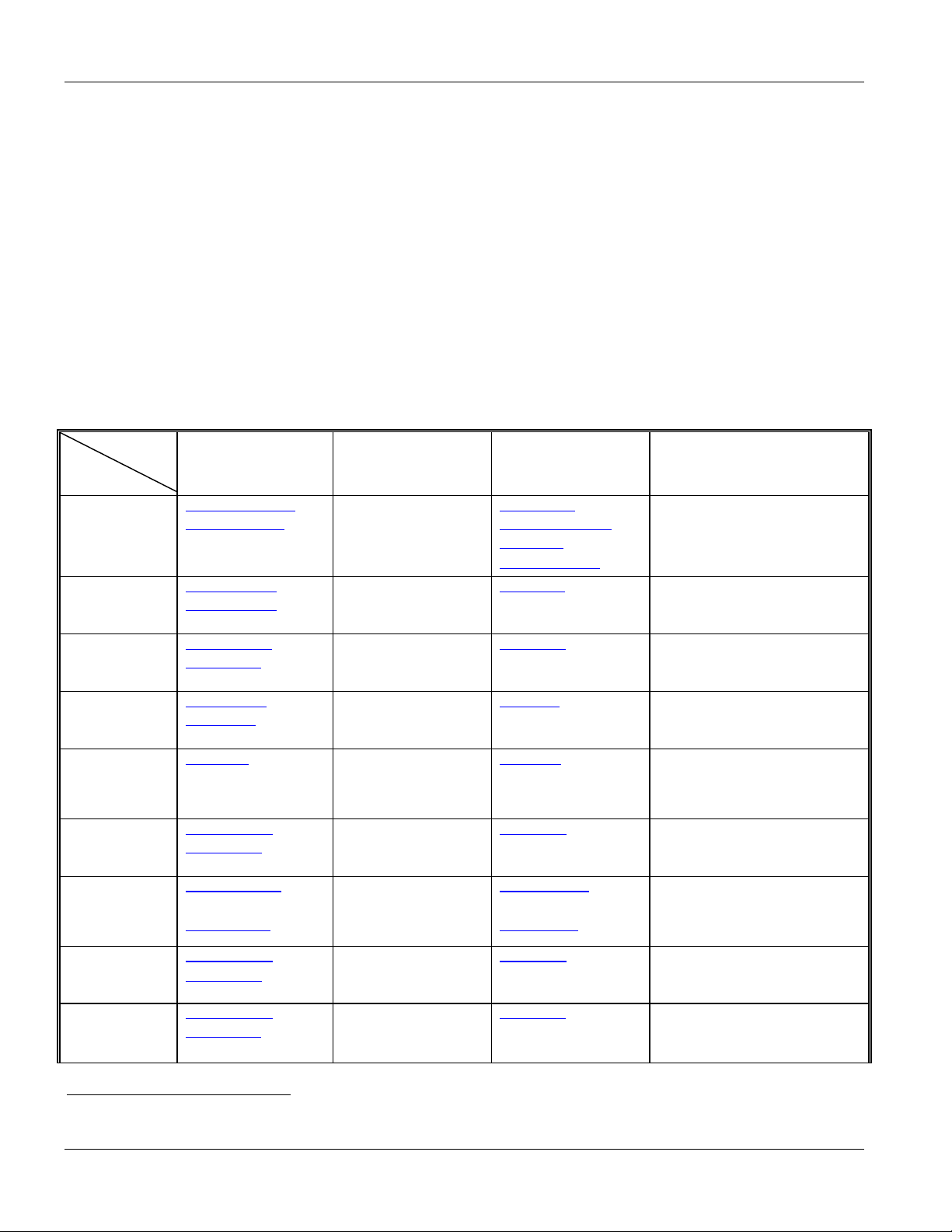
Contacting Customer Support
When you contact your customer support representative, have the following information ready:
♦ Product model and serial number.
♦ Firmware version information.
♦ Warranty information.
♦ Date you received your product.
♦ Brief description of the problem and the steps you took to solve it.
SUPPORT E-MAIL TELEPHONE1 WEB SITE METHOD
LOCATION
CORPORATE
HEADQUARTERS
(WORLDWIDE)
CZECH REPUBLIC info@cz.zyxel.com
DENMARK support@zyxel.dk
FINLAND support@zyxel.fi
FRANCE info@zyxel.fr +33 (0)4 72 52 97 97
GERMANY support@zyxel.de
SPAIN support@zyxel.es
SALES E-MAIL FAX1 FTP SITE
support@zyxel.com.tw
sales@zyxel.com.tw
ftp.europe.zyxel.com
info@cz.zyxel.com
sales@zyxel.dk
sales@zyxel.fi
sales@zyxel.de
support@zyxel.com +1-800-255-4101
sales@zyxel.com
support@zyxel.no +47 22 80 61 80 www.zyxel.no NORWAY
sales@zyxel.no
sales@zyxel.es
+1-714-632-0858 ftp.us.zyxel.com
+47 22 80 61 81
+886-3-578-3942
+886-3-578-2439
+420 241 091 350
+420 241 091 359
+45 39 55 07 00
+45 39 55 07 07
+358-9-4780-8411
+358-9-4780 8448
+33 (0)4 72 52 19 20
+49-2405-6909-0
+49-2405-6909-99
+1-714-632-0882
+34 902 195 420
+34 913 005 345
www.zyxel.com
www.europe.zyxel.com
ftp.zyxel.com
www.zyxel.cz
www.zyxel.dk
www.zyxel.fi
www.zyxel.fr ZyXEL France
www.zyxel.de
www.us.zyxel.com NORTH AMERICA
www.zyxel.es
ZyXEL Communications Czech s.r.o.
ZyXEL Communications A/S
ZyXEL Communications Oy
ZyXEL Deutschland GmbH. Adenauerstr.
ZyXEL Communications
ZyXEL Communications Corp.
6 Innovation Road II
Science Park
Hsinchu 300
Taiwan
Modranská 621
143 01 Praha 4 – Modrany
Ceská Republika
Columbusvej 5
2860 Soeborg
Denmark
Malminkaari 10
00700 Helsinki
Finland
1 rue des Vergers
Bat. 1 / C
69760 Limonest
France
20/A2 D-52146
Wuerselen
Germany
ZyXEL Communications Inc.
1130 N. Miller St.
Anaheim
CA 92806-2001
U.S.A.
ZyXEL Communications A/S
Nils Hansens vei 13
0667 Oslo
Norway
Alejandro Villegas 33
1º, 28043 Madrid
Spain
REGULAR MAIL
1
“+” is the (prefix) number you enter to make an international telephone call.
vi Customer Support
Page 7

IES-1248 User’s Guide
SUPPORT E-MAIL TELEPHONE1 WEB SITE METHOD
LOCATION
SWEDEN support@zyxel.se
UNITED KINGDOM support@zyxel.co.uk
SALES E-MAIL FAX1 FTP SITE
sales@zyxel.se
sales@zyxel.co.uk
+46 31 744 7700
+46 31 744 7701
+44 (0) 8702 909090
+44 (0) 8702 909091
0906 7370001(UK only)
www.zyxel.se
www.zyxel.co.uk
ftp.zyxel.co.uk
ZyXEL Communications A/S
REGULAR MAIL
Sjöporten 4, 41764 Göteborg
Sweden
ZyXEL Communications UK
Ltd.,11 The Courtyard,
Eastern Road, Bracknell,
Berkshire, RG12 2XB,
United Kingdom (UK)
Customer Support vii
Page 8

IES-1248 User’s Guide
Table of Contents
Copyright .......................................................................................................................................................................ii
Interference Statements and Warnings........................................................................................................................iii
Safety Warnings ...........................................................................................................................................................iv
ZyXEL Limited Warranty............................................................................................................................................... v
Customer Support ........................................................................................................................................................vi
List of Figures ..............................................................................................................................................................xv
List of Tables ...............................................................................................................................................................xx
Preface ..................................................................................................................................................................... xxiii
Chapter 1 Getting to know the IES-1248............................................................................................................... 1-1
1.1 Integrated Ethernet Switch Overview .................................................................................................... 1-1
1.2 System Description................................................................................................................................ 1-1
1.3 Applications ...........................................................................................................................................1-4
Chapter 2 Hardware Installation ............................................................................................................................ 2-1
2.1 General Installation Instructions ............................................................................................................ 2-1
2.2 Installation Scenarios ............................................................................................................................2-1
2.3 Desktop Installation Procedure.............................................................................................................. 2-1
2.4 Rack-mounted Installation Requirements .............................................................................................2-2
2.5 Rack-Mounted Installation .....................................................................................................................2-2
2.6 Connecting the Frame Ground .............................................................................................................. 2-4
Chapter 3 Front Panel Connections ...................................................................................................................... 3-1
3.1 Front Panel (AC Power Version) ........................................................................................................... 3-1
3.2 Front Panel (DC Power Version) ........................................................................................................... 3-1
3.3 IES-1248 Front Panel Ports................................................................................................................... 3-1
3.4 Front Panel LEDs ..................................................................................................................................3-2
3.5 1000/100M Auto-Sensing Ethernet .......................................................................................................3-2
3.6 SFP Mini GBIC Slots ............................................................................................................................. 3-3
3.7 Console Port Connection....................................................................................................................... 3-5
3.8 ALARM Connections .............................................................................................................................3-6
3.9 ADSL Connections ................................................................................................................................3-6
Chapter 4 MDF Connections ................................................................................................................................. 4-1
viii Table of Contents
Page 9

IES-1248 User’s Guide
4.1 MDF Connections Overview.................................................................................................................. 4-1
4.2 MDF (Main Distribution Frame) ............................................................................................................. 4-1
4.3 Telco-50 Cables ....................................................................................................................................4-2
4.4 Telco-50 Connections ........................................................................................................................... 4-2
4.5 MDF Scenarios...................................................................................................................................... 4-2
4.6 Typical MDF Scenarios ......................................................................................................................... 4-3
Chapter 5 Power Connections .............................................................................................................................. 5-1
5.1 Power Connections Overview ............................................................................................................... 5-1
5.2 Power Connections ............................................................................................................................... 5-1
5.3 Procedure to Turn on the IES-1248 Power ........................................................................................... 5-2
Chapter 6 Fan Maintenance.................................................................................................................................. 6-1
6.1 Fan Maintenance Introduction............................................................................................................... 6-1
6.2 Removing and Installing the Fan Module.............................................................................................. 6-1
Chapter 7 Web Configurator Introduction ............................................................................................................. 7-1
7.1 Web Configurator Overview .................................................................................................................. 7-1
7.2 Accessing the Web Configurator........................................................................................................... 7-1
7.3 Home Screen......................................................................................................................................... 7-1
7.4 Saving Your Configuration .................................................................................................................... 7-5
Chapter 8 Initial Configuration............................................................................................................................... 8-1
8.1 Initial Configuration Overview................................................................................................................ 8-1
8.2 Initial Configuration................................................................................................................................ 8-1
8.3 Default Settings ..................................................................................................................................... 8-6
Chapter 9 Home and Port Statistics Screens........................................................................................................ 9-1
9.1 Home and Port Statistics Screens Overview ........................................................................................ 9-1
9.2 Home Screen......................................................................................................................................... 9-1
Chapter 10 Basic Setting Screens ...................................................................................................................... 10-1
10.1 Basic Setting Screens Overview ......................................................................................................... 10-1
10.2 System Information.............................................................................................................................. 10-1
10.3 General Setup ..................................................................................................................................... 10-5
10.4 IGMP Snooping ................................................................................................................................... 10-6
10.5 Switch Modes ...................................................................................................................................... 10-7
10.6 Switch Setup Screen ........................................................................................................................... 10-9
Table of Contents ix
Page 10

IES-1248 User’s Guide
10.7 IP Setup ............................................................................................................................................. 10-11
10.8 ENET Port Setup ...............................................................................................................................10-12
Chapter 11 ADSL Port Setup............................................................................................................................... 11-1
11.1 ADSL Standards Overview..................................................................................................................11-1
11.2 Downstream and Upstream................................................................................................................. 11-1
11.3 Profiles.................................................................................................................................................11-1
11.4 Interleave Delay...................................................................................................................................11-2
11.5 Configured Versus Actual Rate ........................................................................................................... 11-2
11.6 Default Settings ...................................................................................................................................11-2
11.7 xDSL Port Setup.................................................................................................................................. 11-3
11.8 xDSL Port Setting ................................................................................................................................ 11-5
11.9 Virtual Channels ..................................................................................................................................11-6
11.10 VC Setup Screen ............................................................................................................................. 11-7
11.11 ATM QoS .......................................................................................................................................11-14
11.12 Traffic Shaping............................................................................................................................... 11-14
11.13 Line Rate Information ....................................................................................................................11-22
11.14 Line Performance ..........................................................................................................................11-24
11.15 Line Data .......................................................................................................................................11-27
Chapter 12 VLAN ................................................................................................................................................12-1
12.1 Introduction to VLANs.......................................................................................................................... 12-1
12.2 Introduction to IEEE 802.1Q Tagged VLAN ........................................................................................12-1
12.3 VLAN Status ........................................................................................................................................ 12-3
Chapter 13 IGMP Snooping ................................................................................................................................13-1
13.1 IGMP Snooping ...................................................................................................................................13-1
13.2 IGMP Snooping Screen.......................................................................................................................13-1
Chapter 14 Static Multicast..................................................................................................................................14-1
14.1 Static Multicast Filter............................................................................................................................14-1
14.2 Static Multicast Screen ........................................................................................................................ 14-1
Chapter 15 Packet Filtering ................................................................................................................................. 15-1
15.1 Packet Filter Configuration .................................................................................................................. 15-1
Chapter 16 MAC Filter.........................................................................................................................................16-1
16.1 MAC Filter Introduction........................................................................................................................16-1
x Table of Contents
Page 11

IES-1248 User’s Guide
16.2 MAC Filter Configuration ..................................................................................................................... 16-1
Chapter 17 Spanning Tree Protocol .................................................................................................................... 17-3
17.1 RSTP (Rapid Spanning Tree Protocol) and STP (Spanning Tree Protocol) ...................................... 17-3
17.2 STP Status .......................................................................................................................................... 17-5
Chapter 18 Port Authentication ........................................................................................................................... 18-1
18.1 Introduction to Authentication.............................................................................................................. 18-1
18.2 Port Authentication Configuration........................................................................................................ 18-1
Chapter 19 Port Security ..................................................................................................................................... 19-1
19.1 About Port Security ............................................................................................................................. 19-1
19.2 Port Security Setup ............................................................................................................................. 19-1
Chapter 20 DHCP Relay ..................................................................................................................................... 20-1
20.1 DHCP Relay ........................................................................................................................................ 20-1
20.2 DHCP Relay Agent Information Option (Option 82)............................................................................ 20-1
20.3 DHCP Relay Setup.............................................................................................................................. 20-1
Chapter 21 Syslog............................................................................................................................................... 21-1
21.1 Syslog.................................................................................................................................................. 21-1
21.2 Syslog Setup ....................................................................................................................................... 21-1
Chapter 22 Access Control.................................................................................................................................. 22-1
22.1 About Access Control.......................................................................................................................... 22-1
22.2 Access Control Overview .................................................................................................................... 22-1
22.3 About SNMP........................................................................................................................................ 22-1
22.4 Service Access Control Configuration................................................................................................. 22-6
22.5 Secured Client Configuration ..............................................................................................................22-7
Chapter 23 Routing Protocol .......................................................................................................................... 23-1
23.1 Static Route ......................................................................................................................................... 23-1
Chapter 24 Maintenance ................................................................................................................................ 24-1
24.1 Maintenance ........................................................................................................................................ 24-1
24.2 Firmware Upgrade............................................................................................................................... 24-1
24.3 Restore a Text Configuration File........................................................................................................ 24-2
24.4 Backing Up a Configuration File.......................................................................................................... 24-2
24.5 Load Factory Defaults ......................................................................................................................... 24-2
24.6 Reboot System.................................................................................................................................... 24-3
Table of Contents xi
Page 12

IES-1248 User’s Guide
24.7 Command Line FTP.............................................................................................................................24-3
Chapter 25 Diagnostic .................................................................................................................................... 25-1
25.1 Diagnostic ............................................................................................................................................ 25-1
25.2 Log Format ..........................................................................................................................................25-2
25.3 Line Diagnostics Test Parameters.......................................................................................................25-4
Chapter 26 MAC Table ...................................................................................................................................26-1
26.1 Introduction to MAC Table...................................................................................................................26-1
26.2 Viewing the MAC Table .......................................................................................................................26-2
Chapter 27 ARP Table .................................................................................................................................... 27-1
27.1 Introduction to ARP Table ...................................................................................................................27-1
27.2 Viewing ARP Table.............................................................................................................................. 27-1
Chapter 28 Commands .......................................................................................................................................28-1
28.1 Command Line Interface Overview .....................................................................................................28-1
28.2 Commands Summary..........................................................................................................................28-1
Chapter 29 Command Examples ........................................................................................................................29-1
29.1 Command Examples Overview ........................................................................................................... 29-1
29.2 Sys Commands ...................................................................................................................................29-1
29.3 Statistics Monitor Command................................................................................................................ 29-2
29.4 Statistics Port Command .....................................................................................................................29-3
Chapter 30 DHCP Relay Commands.................................................................................................................. 30-1
30.1 DHCP Relay Overview ........................................................................................................................30-1
30.2 DHCP Relay Commands.....................................................................................................................30-1
30.3 DHCP Relay Option 82 (Agent Information)........................................................................................ 30-2
Chapter 31 IEEE 802.1Q Tagged VLAN Commands .......................................................................................... 31-1
31.1 IEEE 802.1Q Tagged VLAN Overview................................................................................................ 31-1
31.2 Filtering Databases.............................................................................................................................. 31-1
31.3 IEEE VLAN1Q Tagged VLAN Configuration Commands.................................................................... 31-1
31.4 VLAN Enable ....................................................................................................................................... 31-8
31.5 VLAN Disable ......................................................................................................................................31-9
Chapter 32 MAC Commands ..............................................................................................................................32-1
32.1 MAC Commands Overview ................................................................................................................. 32-1
32.2 MAC Filter Commands ........................................................................................................................ 32-1
xii Table of Contents
Page 13

IES-1248 User’s Guide
32.3 MAC Count Commands ...................................................................................................................... 32-3
Chapter 33 IGMP Filter Commands.................................................................................................................... 33-1
33.1 IGMP Filter Commands....................................................................................................................... 33-1
Chapter 34 Packet Filter Commands .................................................................................................................. 34-1
34.1 Packet Filter Commands ..................................................................................................................... 34-1
Chapter 35 IP Commands................................................................................................................................... 35-1
35.1 IP Commands Introduction.................................................................................................................. 35-1
35.2 IP Settings and Default Gateway ........................................................................................................35-1
35.3 General IP Commands........................................................................................................................ 35-2
35.4 Statistics IP Command ........................................................................................................................ 35-4
Chapter 36 Firmware and Configuration File Maintenance ................................................................................ 36-1
36.1 Firmware and Configuration File Maintenance Overview ................................................................... 36-1
36.2 Filename Conventions......................................................................................................................... 36-1
36.3 Editable Configuration File .................................................................................................................. 36-2
36.4 Firmware File Upgrade........................................................................................................................ 36-4
Chapter 37 SNMP ............................................................................................................................................... 37-1
37.1 SNMP Overview .................................................................................................................................. 37-1
37.2 SNMP Commands............................................................................................................................... 37-1
Chapter 38 ADSL Commands ............................................................................................................................. 38-1
38.1 ADSL Standards Overview.................................................................................................................. 38-1
38.2 Configured Versus Actual Rate........................................................................................................... 38-1
38.4 ADSL Commands................................................................................................................................ 38-1
38.5 Statistics ADSL Commands ................................................................................................................ 38-6
38.6 Alarm Profile Commands .................................................................................................................. 38-14
Chapter 39 Virtual Channel Management........................................................................................................... 39-1
39.1 Virtual Channels Overview .................................................................................................................. 39-1
39.2 Virtual Channel Profile Commands ..................................................................................................... 39-1
39.3 PVC Channels..................................................................................................................................... 39-3
Chapter 40 Troubleshooting................................................................................................................................ 40-1
40.1 The SYS or PWR LED Does Not Turn On .......................................................................................... 40-1
40.2 The ALM LED Is On ............................................................................................................................ 40-1
40.3 SFP LNK LEDs Do Not Turn On ......................................................................................................... 40-1
Table of Contents xiii
Page 14

IES-1248 User’s Guide
40.4 1000/100 LEDs Do Not Turn On ......................................................................................................... 40-2
40.5 1000/100 Ethernet Port Data Transmission ........................................................................................ 40-2
40.6 DSL Data Transmission....................................................................................................................... 40-3
40.7 There Is No Voice on an ADSL Connection ........................................................................................40-3
40.8 Testing Wiring...................................................................................................................................... 40-3
40.9 Local Server.........................................................................................................................................40-5
40.10 Data Rate......................................................................................................................................... 40-5
40.11 Configured Settings ......................................................................................................................... 40-6
40.12 Password .........................................................................................................................................40-6
40.13 SNMP .............................................................................................................................................. 40-6
40.14 Telnet...............................................................................................................................................40-6
40.15 Switch Lockout................................................................................................................................. 40-7
40.16 Resetting the Defaults .....................................................................................................................40-7
40.17 Recovering the Firmware ................................................................................................................40-9
Appendix A Hardware Specifications........................................................................................................................A
Appendix B Removing and Installing a Fuse........................................................................................................... G
Appendix C Virtual Circuit Topology .......................................................................................................................... I
Index .............................................................................................................................................................................K
xiv Table of Contents
Page 15

IES-1248 User’s Guide
List of Figures
Figure 1-1 MTU Application....................................................................................................................................... 1-5
Figure 1-2 Curbside Application ................................................................................................................................ 1-5
Figure 2-1 Attaching Rubber Feet ............................................................................................................................. 2-2
Figure 2-2 Attaching Mounting Brackets and Screws ............................................................................................... 2-3
Figure 2-3 Rack Mounting......................................................................................................................................... 2-3
Figure 2-4 IES-1248 Frame Ground ......................................................................................................................... 2-4
Figure 3-1 Front Panel (AC Power Version).............................................................................................................. 3-1
Figure 3-2 Front Panel (DC Power Version) ............................................................................................................. 3-1
Figure 3-3 SFP Mini GBIC Slot ................................................................................................................................. 3-3
Figure 3-4 Transceiver Installation ............................................................................................................................ 3-4
Figure 3-5 Installed Transceivers .............................................................................................................................. 3-4
Figure 3-6 Opening the Transceiver Latch................................................................................................................ 3-5
Figure 3-7 Removing the Transceiver....................................................................................................................... 3-5
Figure 3-8 ALARM Pins Layout................................................................................................................................. 3-6
Figure 4-1 MDF (Main Distribution Frame) Wiring .................................................................................................... 4-1
Figure 4-2 Telco-50 Cable with RJ-11 Connectors.................................................................................................... 4-2
Figure 4-3 Installation Overview Example................................................................................................................. 4-3
Figure 4-4 Installation Scenario A ............................................................................................................................. 4-4
Figure 4-5 One MDF for End-user and CO Connections.......................................................................................... 4-5
Figure 4-6 Installation Scenario B ............................................................................................................................. 4-5
Figure 4-7 Two Separate MDFs for End-user and CO Connections......................................................................... 4-6
Figure 4-8 Installation Scenario C............................................................................................................................. 4-7
Figure 6-1 Fan Module Thumbscrews....................................................................................................................... 6-1
Figure 6-2 Removing the Fan Module....................................................................................................................... 6-2
Figure 6-3 Fan Module Removed ............................................................................................................................. 6-2
Figure 7-1 Login Screen............................................................................................................................................ 7-1
Figure 7-2 Home Screen ........................................................................................................................................... 7-2
Figure 7-3 Web Configurator: Change Password ..................................................................................................... 7-5
Figure 7-4 Web Configurator Logout......................................................................................................................... 7-5
Figure 8-1 Login Screen............................................................................................................................................ 8-1
Figure 8-2 Basic Setting IP Setup Menu ................................................................................................................... 8-2
List of Figures xv
Page 16

IES-1248 User’s Guide
Figure 8-3 IP Setup....................................................................................................................................................8-2
Figure 8-4 Basic Setting xDSL Port Setup Menu ...................................................................................................... 8-3
Figure 8-5 xDSL Port Setup ......................................................................................................................................8-3
Figure 8-6 Deleting a PVC.........................................................................................................................................8-3
Figure 8-7 Select Ports..............................................................................................................................................8-4
Figure 8-8 Adding a New Channel.............................................................................................................................8-4
Figure 8-9 Copying the PVC......................................................................................................................................8-5
Figure 8-10 Select Ports............................................................................................................................................8-5
Figure 8-11 Config Save Menu.................................................................................................................................. 8-5
Figure 8-12 Config Save Screen ............................................................................................................................... 8-6
Figure 9-1 Home........................................................................................................................................................ 9-1
Figure 9-2 Ethernet Port Statistics.............................................................................................................................9-3
Figure 9-3 ADSL Port Statistics ................................................................................................................................. 9-6
Figure 10-1 System Information .............................................................................................................................. 10-2
Figure 10-2 General Setup ...................................................................................................................................... 10-5
Figure 10-3 Port Isolation with Standalone Switch Mode Example......................................................................... 10-8
Figure 10-4 Port Isolation with Daisychain Switch Mode Example ......................................................................... 10-9
Figure 10-5 Switch Setup ........................................................................................................................................ 10-9
Figure 10-6 IP Setup ............................................................................................................................................. 10-11
Figure 10-7 ENET Port Setup................................................................................................................................10-12
Figure 11-1 xDSL Port Setup................................................................................................................................... 11-3
Figure 11-2 Select Ports .......................................................................................................................................... 11-4
Figure 11-3 xDSL Port Setting................................................................................................................................. 11-5
Figure 11-4 VC Setup .............................................................................................................................................. 11-8
Figure 11-5 Delete Other Channels....................................................................................................................... 11-10
Figure 11-6 Select Ports ........................................................................................................................................ 11-10
Figure 11-7 Select Ports ........................................................................................................................................ 11-11
Figure 11-8 Port Profile.......................................................................................................................................... 11-12
Figure 11-9 PCR, SCR, MCR and MBS in Traffic Shaping ................................................................................... 11-16
Figure 11-10 TAT, CDVT and BT in Traffic Shaping .............................................................................................. 11-16
Figure 11-11 VC Profile.......................................................................................................................................... 11-17
Figure 11-12 Alarm Profile..................................................................................................................................... 11-19
xvi List of Figures
Page 17

IES-1248 User’s Guide
Figure 11-13 IGMP Filter Profile............................................................................................................................ 11-21
Figure 11-14 Line Rate Information....................................................................................................................... 11-23
Figure 11-15 Line Performance............................................................................................................................. 11-25
Figure 11-16 Line Data.......................................................................................................................................... 11-27
Figure 12-1 VLAN Status......................................................................................................................................... 12-3
Figure 12-2 Static VLAN Setting.............................................................................................................................. 12-5
Figure 12-3 VLAN Port Setting................................................................................................................................ 12-7
Figure 12-4 Select Ports.......................................................................................................................................... 12-8
Figure 13-1 IGMP Snooping.................................................................................................................................... 13-1
Figure 14-1 Static Multicast..................................................................................................................................... 14-1
Figure 15-1 Packet Filter ......................................................................................................................................... 15-1
Figure 16-1 MAC Filter ............................................................................................................................................ 16-1
Figure 17-1 STP Root Ports and Designated Ports ................................................................................................ 17-4
Figure 17-2 Spanning Tree Protocol: Status ........................................................................................................... 17-5
Figure 17-3 Spanning Tree Protocol: Configuration................................................................................................ 17-7
Figure 18-1 RADIUS Server.................................................................................................................................... 18-1
Figure 18-2 Port Authentication: RADIUS............................................................................................................... 18-2
Figure 18-3 Port Authentication: 802.1x.................................................................................................................. 18-3
Figure 19-1 Port Security ........................................................................................................................................ 19-1
Figure 20-1 DHCP Relay Agent Circuit ID Sub-option Format ............................................................................... 20-1
Figure 20-2 DHCP Relay......................................................................................................................................... 20-2
Figure 21-1 Syslog .................................................................................................................................................. 21-1
Figure 22-1 Access Control..................................................................................................................................... 22-1
Figure 22-2 Console Port Priority............................................................................................................................ 22-1
Figure 22-3 SNMP Management Model.................................................................................................................. 22-2
Figure 22-4 Access Control: SNMP ........................................................................................................................ 22-4
Figure 22-5 Access Control: Logins ........................................................................................................................ 22-5
Figure 22-6 Access Control: Service Access Control.............................................................................................. 22-6
Figure 22-7 Secured Client Setup........................................................................................................................... 22-7
Figure 23-1 Static Routing....................................................................................................................................... 23-1
Figure 23-2 Static Routing: Summary Table............................................................................................................ 23-2
Figure 24-1 Maintenance ........................................................................................................................................ 24-1
List of Figures xvii
Page 18

IES-1248 User’s Guide
Figure 24-2 Firmware Upgrade ...............................................................................................................................24-1
Figure 24-3 Restore Configuration .......................................................................................................................... 24-2
Figure 24-4 Confirm Restore Factory Default Settings ...........................................................................................24-3
Figure 24-5 Restart After Load Factory Defaults.....................................................................................................24-3
Figure 24-6 Confirm Restart .................................................................................................................................... 24-3
Figure 25-1 Diagnostic ............................................................................................................................................25-1
Figure 26-1 MAC Table Filtering Flowchart ............................................................................................................. 26-2
Figure 26-2 MAC Table............................................................................................................................................ 26-3
Figure 27-1 ARP Table.............................................................................................................................................27-1
Figure 29-1 Log Show Command Example ............................................................................................................29-1
Figure 29-2 Info Show Command Example ............................................................................................................29-2
Figure 29-3 Statistics Monitor Command Example................................................................................................. 29-2
Figure 29-4 Statistics Port Command Example....................................................................................................... 29-3
Figure 30-1 Show Command Example ...................................................................................................................30-2
Figure 31-1 Garptimer Show Command Example ..................................................................................................31-2
Figure 31-2 Garptimer Join Command Example..................................................................................................... 31-2
Figure 31-3 Garptimer Leave Command Example..................................................................................................31-3
Figure 31-4 Garptimer Leaveall Command Example.............................................................................................. 31-3
Figure 31-5 VLAN Port Show Command Example .................................................................................................31-4
Figure 31-6 VLAN PVID Command Example.......................................................................................................... 31-4
Figure 31-7 Modifying the Static VLAN Example .................................................................................................... 31-5
Figure 31-8 VLAN Frame Type Command Example............................................................................................... 31-6
Figure 31-9 CPU VLAN Configuration and Activation Example..............................................................................31-7
Figure 31-10 Deleting Default VLAN Example ........................................................................................................ 31-7
Figure 31-11 VLAN Priority Command Example ..................................................................................................... 31-8
Figure 31-12 VLAN Delete Command Example......................................................................................................31-8
Figure 31-13 VLAN Show Command Example....................................................................................................... 31-9
Figure 32-1 MAC Filter Show Command Example .................................................................................................32-1
Figure 32-2 MAC Count Show Command Example................................................................................................ 32-3
Figure 33-1 IGMP Filter Show Command Example ................................................................................................ 33-1
Figure 33-2 IGMP Filter Show Command Example ................................................................................................ 33-3
Figure 34-1 Packet Filter Show Command Example ..............................................................................................34-1
xviii List of Figures
Page 19

IES-1248 User’s Guide
Figure 35-1 IP Settings and Default Gateway Address........................................................................................... 35-2
Figure 35-2 Route Show Command Example......................................................................................................... 35-3
Figure 35-3 ARP Show Command Example ........................................................................................................... 35-4
Figure 35-4 Statistics IP Command Example.......................................................................................................... 35-4
Figure 36-1 Configuration File Example.................................................................................................................. 36-3
Figure 38-1 ADSL Show Command Example ......................................................................................................... 38-2
Figure 38-2 ADSL Profile Show Command Example.............................................................................................. 38-3
Figure 38-3 ADSL Profile Loopback Example......................................................................................................... 38-6
Figure 38-4 ADSL Show Command Example ......................................................................................................... 38-7
Figure 38-5 Linedata Command Example .............................................................................................................. 38-8
Figure 38-6 Lineinfo Command Example................................................................................................................ 38-9
Figure 38-7 Lineperf Command Example ............................................................................................................. 38-10
Figure 38-8 15 Minute Performance Command Example..................................................................................... 38-11
Figure 38-9 1Day Performance Command Example ............................................................................................ 38-12
Figure 38-10 Line Diagnostics Set Command Example ....................................................................................... 38-13
Figure 38-11 Line Diagnostics Get Command Example ....................................................................................... 38-14
Figure 38-12 Alarm Profile Show Command Example.......................................................................................... 38-15
Figure 38-13 Alarm Profile Showmap Command Example................................................................................... 38-17
Figure 40-1 Testing In-house Wiring ....................................................................................................................... 40-4
Figure 40-2 Resetting the Switch Via Command .................................................................................................... 40-8
Figure 40-3 Example Xmodem Upload ................................................................................................................... 40-8
Figure 40-4 Example Xmodem Upload ................................................................................................................... 40-9
List of Figures xix
Page 20

IES-1248 User’s Guide
List of Tables
Table 3-1 IES-1248 Front Panel Ports....................................................................................................................... 3-1
Table 3-2 LED Descriptions ....................................................................................................................................... 3-2
Table 7-1 Navigation Panel Sub-links Overview........................................................................................................7-3
Table 7-2 Web Configurator Screens ........................................................................................................................7-3
Table 8-1 Default Settings ......................................................................................................................................... 8-6
Table 9-1 Home .........................................................................................................................................................9-2
Table 9-2 Ethernet Port Statistics ..............................................................................................................................9-3
Table 9-3 ADSL Port Statistics................................................................................................................................... 9-6
Table 10-1 System Information................................................................................................................................ 10-2
Table 10-2 General Setup........................................................................................................................................10-5
Table 10-3 Switch Setup........................................................................................................................................10-10
Table 10-4 IP Setup ...............................................................................................................................................10-12
Table 10-5 ENET Port Setup .................................................................................................................................10-12
Table 11-1 Maximum Transfer Rates of the ADSL Ports ......................................................................................... 11-1
Table 11-2 xDSL Port Setup .................................................................................................................................... 11-3
Table 11-3 xDSL Port Setup .................................................................................................................................... 11-5
Table 11-4 VC Setup................................................................................................................................................ 11-8
Table 11-5 Port Profile ........................................................................................................................................... 11-12
Table 11-6 VC Profile............................................................................................................................................. 11-17
Table 11-7 Alarm Profile......................................................................................................................................... 11-19
Table 11-8 IGMP Filter Profile................................................................................................................................ 11-22
Table 11-9 Line Rate Information........................................................................................................................... 11-23
Table 11-10 Line Performance............................................................................................................................... 11-25
Table 11-11 Line Data............................................................................................................................................ 11-27
Table 12-1 GARP Terminology ................................................................................................................................12-3
Table 12-2 VLAN Status ..........................................................................................................................................12-4
Table 12-3 Static VLAN Setting ...............................................................................................................................12-5
Table 12-4 VLAN Port Setting..................................................................................................................................12-7
Table 13-1 IGMP Snooping ..................................................................................................................................... 13-1
Table 14-1 Static Multicast.......................................................................................................................................14-1
Table 15-1 Packet Filter...........................................................................................................................................15-1
xx List of Tables
Page 21

IES-1248 User’s Guide
Table 16-1 MAC Filter.............................................................................................................................................. 16-1
Table 17-1 Path Cost............................................................................................................................................... 17-3
Table 17-2 RSTP Port States ..................................................................................................................................17-4
Table 17-3 Spanning Tree Protocol: Status............................................................................................................. 17-5
Table 17-4 Spanning Tree Protocol: Configuration..................................................................................................17-7
Table 18-1 Port Authentication: RADIUS................................................................................................................. 18-2
Table 18-2 Port Authentication: 802.1x ................................................................................................................... 18-4
Table 19-1 Port Security .......................................................................................................................................... 19-1
Table 20-1 DHCP Relay .......................................................................................................................................... 20-2
Table 21-1 Syslog.................................................................................................................................................... 21-1
Table 22-1 Access Control Summary ...................................................................................................................... 22-1
Table 22-2 SNMP Commands................................................................................................................................. 22-2
Table 22-3 RFC-1215 SNMP Traps......................................................................................................................... 22-3
Table 22-4 ADSL Line SNMP Traps ........................................................................................................................ 22-3
Table 22-5 ZyXEL Private MIB SNMP Traps........................................................................................................... 22-4
Table 22-6 Access Control: SNMP .......................................................................................................................... 22-5
Table 22-7 Access Control: Logins.......................................................................................................................... 22-6
Table 22-8 Access Control: Service Access Control ............................................................................................... 22-6
Table 22-9 Secured Client Setup ............................................................................................................................ 22-7
Table 23-1 Static Routing ........................................................................................................................................ 23-1
Table 23-2 Static Routing: Summary Table ............................................................................................................. 23-2
Table 25-1 Diagnostic .............................................................................................................................................. 25-2
Table 25-2 Log Format ............................................................................................................................................ 25-2
Table 25-3 Log Messages ....................................................................................................................................... 25-3
Table 25-4 Line Diagnostics Test Parameters......................................................................................................... 25-4
Table 26-1 MAC Table............................................................................................................................................. 26-3
Table 27-1 ARP Table .............................................................................................................................................. 27-2
Table 28-1 Commands ............................................................................................................................................ 28-2
Table 36-1 Filename Conventions........................................................................................................................... 36-2
Table 38-1 Line Performance Counters ................................................................................................................ 38-10
Table 38-2 15 Minute Performance Counters ....................................................................................................... 38-11
Table 40-1 SYS LED Troubleshooting..................................................................................................................... 40-1
List of Tables xxi
Page 22

IES-1248 User’s Guide
Table 40-2 ALM LED Troubleshooting..................................................................................................................... 40-1
Table 40-3 SFP LNK LED Troubleshooting ............................................................................................................. 40-2
Table 40-4 1000/100 LED Troubleshooting .............................................................................................................40-2
Table 40-5 Ethernet Port Data Transmission Troubleshooting................................................................................ 40-2
Table 40-6 DSL Data Transmission Troubleshooting .............................................................................................. 40-3
Table 40-7 ADSL Voice Troubleshooting ................................................................................................................. 40-3
Table 40-8 Testing In-house Wiring ......................................................................................................................... 40-4
Table 40-9 Local Server Troubleshooting................................................................................................................ 40-5
Table 40-10 SYNC-rate Troubleshooting................................................................................................................. 40-5
Table 40-11 Configured Settings Troubleshooting...................................................................................................40-6
Table 40-12 SNMP Server Troubleshooting ............................................................................................................ 40-6
Table 40-13 Telnet Troubleshooting.........................................................................................................................40-6
xxii List of Tables
Page 23

IES-1248 User’s Guide
Preface
About this User’s Manual
This user’s guide gives hardware specifications and explains web configurator and command line configuration,
management, and troubleshooting for the IES-1248 Integrated Ethernet Switch.
Online Registration
Register your ZyXEL product online at www.zyxel.com for free future product updates and information.
General Syntax Conventions
Mouse action sequences are denoted using a comma. For example, click Start, Settings, Control Panel,
Network means first you click Start, click or move the mouse pointer over Settings, then click or move
the mouse pointer over Control Panel and finally click (or double-click) Network.
“Enter” means for you to type one or more characters. “Select” or “Choose” means for you to use one of
the predefined choices.
Predefined choices are in Bold Arial font.
Button and field labels, links and screen names in are in Bold Times New Roman font.
A single keystroke is in Arial font and enclosed in square brackets. [ENTER] means the Enter, or carriage
return key; [ESC] means the Escape key and [SPACE BAR] means the Space Bar.
For brevity’s sake, we will use “e.g.,” as shorthand for “for instance”, and “i.e.,” for “that is” or “in other
words”.
Naming Conventions
• The IES-1248 Integrated Ethernet Switch may be referred to as the IES-1248, the IES, the switch or,
simply, as the device.
• “IES-1248” refers to the IES-1248-71 for ADSL over POTS (Annex A). “IES-1248” also refers to the
IES-1248-73 for ADSL over ISDN (Annex B). Differentiation is made where needed.
• This user’s guide refers to an Ethernet device as a switch in general for feature background information.
Related Documentation
Web Configurator Online Help
Embedded web help for descriptions of individual screens and supplementary information.
Glossary and ZyXEL Web Site
Please refer to www.zyxel.com for an online glossary of networking terms or the ZyXEL download library for
additional support documentation.
Preface xxiii
Page 24

IES-1248 User’s Guide
Firmware Naming Conventions
A firmware version includes the model code and release number as shown in the following example.
Firmware Version: V3.50(LS.0)
“LS” is the model code.
“LS” denotes the IES-1248-71 for ADSL over POTS (Annex A).
“TR” denotes the IES-1248-73 for ADSL over ISDN (Annex B).
“0” is this firmware’s release number. This varies as new firmware is released. Your firmware’s release
number may not match what is displayed in this User’s Guide.
.
xxiv Preface
Page 25

IES-1248 Overview
Part I:
IES-1248 Overview
This part introduces the general features and default settings of the Integrated Ethernet Switch.
I
Page 26

Page 27

IES-1248 User’s Guide
Chapter 1
Getting to know the IES-1248
This chapter describes the key features and applications of your IES-1248
1.1 Integrated Ethernet Switch Overview
The Integrated Ethernet Switch is an IP-based DSLAM (Internet Protocol Digital Subscriber Line Access
Multiplexer) that connects ADSL subscribers to the Internet.
As a high-performance yet compact platform, the IES-124 can conveniently deliver broadband Internet access to
telephone company central offices, multi-tenant units (MTUs), hospitals, hotels, schools, university campuses and
ISPs. The IES-1248’s low cost and easy management make it a perfect DSL-provider solution.
The IES-1248 provides ADSL service for 48 subscribers over existing telephone wiring, thus avoiding the cost and
hassle of installing new wiring. ADSL allows you to extend the reach of broadband services up to 18,000 feet. This
makes the IES-1248 perfect for providing high bandwidth broadband service to subscribers who are spread out over
a large area. The built in splitter combines voice service and ADSL on the same telephone wiring.
The IES-1248 is easy to manage.
1.2 System Description
Four Telco-50 Connectors
There are four Telco-50 connectors for ADSL and POTS connections.
1000/100 Mbps Ethernet Ports
The IES-1248 has two 1000/100Mbps auto-negotiating, auto-crossover Ethernet ports.
They allow you to:
Connect the IES-1248 to a second level switch
Daisy-chain other switches
Two Slots for Mini GBIC Modules
The mini GBIC (Gigabit Interface Converter) module transceivers allow flexibility in connection options. You can
use mini GBIC transceivers for fiber connections to backbone Ethernet switches.
Stacking
Daisy-chain up to three IES-1248s (or other Ethernet devices).
Integrated Splitters
The integrated DSL splitter eliminates the need to use external splitters that separate the voice-band and ADSL
signals.
Getting to know the IES-1248 1-1
Page 28

IES-1248 User’s Guide
Console Port
Use the console port for local management of the IES-1248.
Fans
The fans cool the IES-1248 sufficiently to allow reliable operation of the IES-1248, even in poorly ventilated rooms
or basements.
IP Protocols
IP Host (No routing)
Telnet for configuration and monitoring
SNMP for management
• SNMP MIB II (RFC 1213)
• SNMP v1 RFC 1157
• SNMPv2, SNMPv2c or later version, compliant with RFC 2011 SNMPv2 MIB for IP, RFC 2012
SNMPv2 MIB for TCP, RFC 2013 SNMPv2 MIB for UDP
• Ethernet MIBs RFC 1643
• Bridge MIBs (RFC 1493, 2674)
• SMI RFC 1155
• Multiple Protocols over AAL5 (RFC 1483)
ADSL Compliance
• Multi-Mode ADSL standard
G.dmt (ITU-T G.992.1)
G.lite (ITU-T G.992.2)
G.hs (ITU-T G.994.1)
ANSI T1.413 issue 2
ADSL2: ITU-T G.992.3, G.992.4
ADSL2+: ITU-T G.992.5
• Rate adaptation support
IEEE 802.1p Priority
1
Your IES-1248 uses IEEE 802.1p Priority to assign priority levels to individual PVCs.
Multiple PVC and ATM QoS
1
At the time of writing, the IES-1248 only supports the line rates for ADSL2 and ADSL2+ (not other features); and the IES-
1248’s interoperability when using ADSL2 and ADSL2+ has not yet been tested.
1-2 Getting to know the IES-1248
Page 29

IES-1248 User’s Guide
The IES-1248 allows you to use different channels (also called Permanent Virtual Circuits or PVCs) for different
services or subscribers. Define channels
2
on each DSL port for different services or levels of service and assign
each channel a priority. ATM Quality of Service (QoS) allows you to regulate the average rate and fluctuations of
data transmission. This helps eliminate congestion to allow the transmission of real time data (such as audio and
video).
IEEE 802.1x Port-based Authentication
The IES-1248 supports the IEEE 802.1x standard for centralized user authentication and accounting management
through an optional network authentication (RADIUS) server.
Management
• Remote configuration backup/restore and firmware upgrade
• SNMP manageable
• Text-based management locally via console port and remotely via telnet
• Editable plain text based configuration file
Security
Password protection for system management
VLAN
MAC (Media Access Control) Count Filter
You can limit the number of MAC addresses that may be dynamically learned on a port. You may enable/disable
the MAC count filter on individual ports.
Static Multicast Filter
Use the static multicast filter to allow incoming frames based on multicast MAC address(es) that you specify. This
feature can be used in conjunction with IGMP snooping to allow multicast MAC address(es) that are not learned by
IGMP snooping.
IGMP Snooping
With IGMP snooping, group multicast traffic is only forwarded to ports that are members of that group. IGMP
Snooping generates no additional network traffic, allowing you to significantly reduce multicast traffic passing
through your IES-1248.
System Monitoring
• System status (link status, rates, statistics counters)
• Temperatures, voltage reports and alarms.
System Error Logging
2
Up to eight channels on each DSL port at the time of writing.
Getting to know the IES-1248 1-3
Page 30

IES-1248 User’s Guide
The IES-1248’s system error log will record error logs locally. These logs may be viewed again after a warm
restart.
Alarm LED
An ALM (alarm) LED lights when the IES-1248 is overheated, the fans are not working properly, the voltage
readings are outside the tolerance levels or an alarm has been detected on the ALARM input pins.
Bandwidth Control
The IES-1248 supports rate limiting in 64Kbps increments allowing you to create different service plans
Quality of Service
The IES-1248 has four priority queues so you can ensure mission-critical data gets delivered on time.
Follows the IEEE 802.1p priority setting standard.
Flow Control
The IES-1248 uses IEEE 802.3 flow control to manage the sending of traffic so the sending device does not
transmit more than the receiving device can process. This helps prevent traffic from being dropped and having to be
resent.
1.3 Applications
These are the main applications for the IES-1248:
Internet access and multimedia services for Multiple Tenant Units (MTU).
Other applications include telemedicine, surveillance systems, remote servers systems, cellular base
stations and high-quality teleconferencing.
1.3.1 MTU Application
The following diagram depicts a typical application of the IES-1248 with ADSL modems, in a large residential
building, or multiple tenant unit (MTU), that leverages existing phone line wiring to provide Internet access to all
tenants. ADSL service can coexist with voice service on the same line.
1-4 Getting to know the IES-1248
Page 31

IES-1248 User’s Guide
Figure 1-1 MTU Application
1.3.2 Curbside Application
The IES-1248 can also be used by an Internet Service Provider (ISP) in a street cabinet to form a “mini POP (Pointof-Presence)” to provide broadband services to residential areas that are too far away from the ISP to avail of DSL
services. Residents need an ADSL modem, connected as shown in the previous figure.
Figure 1-2 Curbside Application
Getting to know the IES-1248 1-5
Page 32

Page 33

Hardware
Part II:
Hardware
This part covers hardware installation, connections and maintenance for the Integrated Ethernet
Switch.
II
Page 34

Page 35

IES-1248 User’s Guide
Chapter 2
Hardware Installation
This chapter shows two installation scenarios.
2.1 General Installation Instructions
Read all the safety warnings in the beginning of this User’s Guide before you begin and make sure you follow
them.
Perform the installation as follows:
1. Make sure the IES-1248 power switch (located on the front panel) is in the OFF position.
2. Install the hardware first.
3. Make the front panel connections next (see Chapter 3 Front Panel Connections and Chapter 4 MDF
Connections).
4. See Chapter 5 Power Connections chapter for instructions on making power connections and turning on
the IES-1248.
2.2 Installation Scenarios
The IES-1248 can be placed on a desktop or rack-mounted on a standard EIA rack. Use the rubber feet in a desktop
installation and the brackets in a rack-mounted installation.
For proper ventilation, allow at least 4 inches (10 cm) of clearance at the front and 3.4 inches (8 cm) at the back of
the switch. This is especially important for enclosed rack installations.
2.3 Desktop Installation Procedure
1. Make sure the switch is clean and dry.
2. Set the switch on a smooth, level surface strong enough to support the weight of the switch and the
connected cables. Make sure there is a power outlet nearby.
3. Make sure there is enough clearance around the switch to allow air circulation and the attachment of cables
and the power cord.
4. Remove the adhesive backing from the rubber feet.
5. Attach the rubber feet to each corner on the bottom of the switch. These rubber feet help protect the switch
from shock or vibration and ensure space between switches when stacking.
Hardware Installation 2-1
Page 36

IES-1248 User’s Guide
Figure 2-1 Attaching Rubber Feet
Do not block the ventilation holes. Leave space between switches when stacking.
2.4 Rack-mounted Installation Requirements
The switch can be mounted on an EIA standard size, 19-inch rack or in a wiring closet with other equipment.
Follow the steps below to mount your switch on a standard EIA rack using a rack-mounting kit.
Make sure the rack will safely support the combined weight of all the equipment it contains.
Make sure the position of the IES-1248 does not make the rack unstable or top-heavy. Take all
necessary precautions to anchor the rack securely before installing the unit.
Use a #2 Philips screwdriver to install the screws.
Refer to the appendices for the gauge of wire to use for the frame ground connections.
Refer to the appendices for the hardware that is required to mount the IES-1248.
Failure to use the proper screws may damage the unit.
Do not block the ventilation holes. Leave space between IES-1248s when stacking.
2.5 Rack-Mounted Installation
1. Align one bracket with the holes on one side of the switch and secure it with the bracket screws (smaller
than the rack-mounting screws).
2. Attach the other bracket in a similar fashion.
2-2 Hardware Installation
Page 37

IES-1248 User’s Guide
Figure 2-2 Attaching Mounting Brackets and Screws
3. After attaching both mounting brackets, position the switch in the rack by lining up the holes in the
brackets with the appropriate holes on the rack. Secure the switch to the rack with the rack-mounting
screws.
Figure 2-3 Rack Mounting
Hardware Installation 2-3
Page 38

IES-1248 User’s Guide
2.6 Connecting the Frame Ground
Refer to the Hardware Specifications Appendix for the ground wire gauge.
The IES-1248 frame ground is on the lower left corner of the front panel.
Connect the frame grounds to a building’s protective earthing terminals using a green-and-yellow frame
ground wire.
Warning!
Connect the frame ground before you connect any other cables or wiring.
Frame Ground
Figure 2-4 IES-1248 Frame Ground
2-4 Hardware Installation
Page 39

Front Panel Connections
This chapter explains how to make connections to the IES-1248’s front panel.
3.1 Front Panel (AC Power Version)
The following figure shows the front panel of AC power version of the IES-1248.
Figure 3-1 Front Panel (AC Power Version)
IES-1248 User’s Guide
Chapter 3
3.2 Front Panel (DC Power Version)
The following figure shows the front panel of DC power version of the IES-1248.
Figure 3-2 Front Panel (DC Power Version)
3.3 IES-1248 Front Panel Ports
Table 3-1 IES-1248 Front Panel Ports
CONNECTOR DESCRIPTION
CONSOLE Connect this mini-RJ-11 port to a computer for local management.
1000/100 1/2 Use these RJ-45 ports for connecting to other Ethernet devices. You can daisy chain
more IES-1248s or other Ethernet switches.
This is an electrical Ethernet interface for use with the following copper Ethernet cables:
1000Base-T 4-pair UTP Cat. 5, up to 100m
For better performance and lower radiation noise, use shielded Ethernet
cables.
Front Panel Connections 3-1
Page 40

IES-1248 User’s Guide
Table 3-1 IES-1248 Front Panel Ports
CONNECTOR DESCRIPTION
ALARM This DB9 connector has alarm input pins and alarm output pins.
Connect the alarm input pins to alarm output terminals on other pieces of equipment.
Connect the alarm output pins to an alarm input terminal on another piece of
equipment.
SFP 1, 2 Each of these Small Form-factor Pluggable (SFP) slots can house a mini GBIC (Gigabit
Interface Converter) transceiver.
USER 1-24, 25-48 Connect these Telco-50 connectors to subscribers 1-24 and 25-48 respectively.
CO 1-24, 25-48 Connect these Telco-50 connectors to the telephone company for subscribers 1-24 and
25-48 respectively.
3.4 Front Panel LEDs
The following table describes the LED indicators on the front panel of the IES-1248.
Table 3-2 LED Descriptions
LED COLOR STATUS DESCRIPTION
On The system is turned on. PWR Green
Off The system is off.
SYS Green
Yellow
1,2
On The link to a 1000 Mbps (1Gbps) Ethernet network is up.
LNK
ACT
Green
Green On The link to a 1000 Mbps (1 Gbps) Ethernet network is up. SFP 1,2
Off There is not a link to a 1000 Mbps (1 Gbps) Ethernet network or the
Yellow
Blinking The system is rebooting and performing self-diagnostic tests.
On The system is on and functioning properly.
Off The power is off or the system is not ready/malfunctioning.
On There is a hardware failure. ALM Red
Off The system is functioning normally.
On The link to a 100 Mbps Ethernet network is up. 1000/100
Off The link to a 100 Mbps Ethernet network is down.
Off The link to a 1000 Mbps (1Gbps) Ethernet network is down.
1000 Mbps network link is down.
Blinking The system is transmitting/receiving Ethernet traffic. SFP 1,2
Off The system is not transmitting/receiving Ethernet traffic.
3.5 1000/100M Auto-Sensing Ethernet
The IES-1248 has two 1000/100Mbps auto-sensing Ethernet ports. There are two factors related to Ethernet: speed
and duplex mode. In 1000/100Mbps Fast Ethernet, the speed can be 100Mbps or 1000Mbps and the duplex mode
can be half duplex or full duplex. The auto-negotiation capability makes one Ethernet port able to negotiate with a
peer automatically to obtain the connection speed and duplex mode that both ends support.
3-2 Front Panel Connections
Page 41

IES-1248 User’s Guide
When auto-negotiation is turned on, an Ethernet port on the IES-1248 negotiates with the peer automatically to
determine the connection speed and duplex mode. If the peer Ethernet port does not support auto-negotiation or
turns off this feature, the IES-1248 determines the connection speed by detecting the signal on the cable and using
half duplex mode. When the IES-1248’s auto-negotiation is turned off, an Ethernet port uses the pre-configured
speed and duplex mode when making a connection, thus requiring you to make sure that the settings of the peer
Ethernet port are the same in order to connect.
Each 1000/100M RJ-45 Ethernet port is paired with a mini GBIC slot. The IES-1248 uses up to one connection for
each pair for a total of two possible gigabit connections (one from each of the two pairs).
When the IES-1248 is in standalone mode (default), you can connect both of the Ethernet ports to the Ethernet
backbone. You can use it with a ring network configuration (you must also enable RSTP).
When the IES-1248 is in daisychain mode, connect Ethernet port 1 to the Ethernet backbone and connect Ethernet
port 2 to another IES-1248 or other Ethernet switch.
3.6 SFP Mini GBIC Slots
The SFP slots can each house a mini GBIC (Gigabit Interface Converter) transceiver. A transceiver is a single unit
that houses a transmitter and a receiver. The IES-1248 does not come with a transceiver. You must use a transceiver
that complies with the Small Form-factor Pluggable (SFP) Transceiver MultiSource Agreement (MSA). See the
SFF committee’s INF-8074i specification Rev 1.0 for details.
You can change transceivers while the IES-1248 is operating. You can use different transceivers to connect to
Ethernet switches with different types of fiber-optic connectors.
To avoid possible eye injury, do not look directly into an operating fiber-optic module’s
connectors.
Figure 3-3 SFP Mini GBIC Slot
Type: SFP connection interface
Connection speed: 1 Gigabit per second (Gbps)
3.6.1 Transceiver Installation
Use the following steps to install a mini GBIC transceiver (SFP module) in the SFP slot.
The SFP slot is at an angle. Do not attempt to straighten it.
1. Remove the dust cover from the transceiver.
2. For transceivers with a flip-up or flip-down latch, close the latch.
Front Panel Connections 3-3
Page 42

IES-1248 User’s Guide
3. Insert the fiber-optic cables into the transceiver (you may need to remove cable dust covers).
4. Insert the transceiver into the IES-1248’s SFP slot with the exposed section of PCB board facing down.
5. Press the transceiver firmly until it clicks into place.
Figure 3-4 Transceiver Installation
Figure 3-5 Installed Transceivers
3.6.2 Transceiver Removal
Use the following steps to remove a mini GBIC transceiver (SFP module) from the IES-1248-GBA module.
1. Remove the fiber-optic cables from the transceiver.
3-4 Front Panel Connections
Page 43

2. Unlock the transceiver’s latch (latch styles vary).
3. Pull the transceiver out of the slot.
4. Put the transceiver’s dust cover on the transceiver.
IES-1248 User’s Guide
Figure 3-6 Opening the Transceiver Latch
Figure 3-7 Removing the Transceiver
3.7 Console Port Connection
For local management, you can use a computer with terminal emulation software configured to the following
parameters:
VT100 terminal emulation 9600 bps
Front Panel Connections 3-5
Page 44

IES-1248 User’s Guide
No parity, 8 data bits, 1 stop bit No flow control
Connect the mini-RJ-11 male end of the console cable to the console port of the IES-1248. Connect the female end
to a serial port (COM1, COM2 or other COM port) of your computer.
3.8 ALARM Connections
A closed circuit on the ALARM input pins indicates an alarm. Pins 7 and 3 are alarm input one. Pins 8 and 4 are
alarm input two. Pins 9 and 5 are alarm input 3.
The IES-1248 signals an alarm when it detects an alarm on the ALARM input pins or the IES-1248.
To signal an alarm, the IES-1248 opens the circuit for pins 1 and 6 (the common pin) and closes the circuit for pins
2 and 6.
Examples of an alarm on the IES-1248 are when the IES-1248’s voltage or temperature is outside of the normal
range.
Pin 5
Pin 9
Figure 3-8 ALARM Pins Layout
Pin 1
Pin 6
3.9 ADSL Connections
Connect the lines from the user equipment (ADSL modems) to the USER Telco-50 connector and the lines from
the central office switch or PBX (Private Branch Exchange) to the
USER line and the CO lines are not shorted on the MDF (Main Distribution Frame).
The line from the user carries both the ADSL and the voice signals. For each line, the IES-1248 has a built-in
splitter that separates the high frequency ADSL signal from the voice band signal and feeds the ADSL signal to the
IES-1248, while the voice band signal is diverted to the CO port. See Chapter 4 for more information on the Telco-
50 connections.
3.9.1 Ethernet Default Settings
CO Telco-50 connector . Make sure that the
The factory default settings for the Ethernet ports of the IES-1248 are:
Speed: Auto
Duplex: Auto
Flow control: Enable
Trunking: Disabled
3-6 Front Panel Connections
Page 45

IES-1248 User’s Guide
Chapter 4
MDF Connections
This chapter shows you how to connect the Telco-50 connectors to an MDF.
4.1 MDF Connections Overview
Observe the following before you start:
Refer to the Hardware Specifications Appendix for the gauge of telephone wire to use.
Follow the pin assignments shown in Hardware Specifications Appendix to wire Telco-50 cables to Telco-
50 connectors.
4.2 MDF (Main Distribution Frame)
An MDF is usually installed between subscribers’ equipment and the telephone company (CO) in a basement or
telephone room. The MDF is the point of termination for the outside telephone company lines coming into a
building and the telephone wiring in the building.
Figure 4-1 MDF (Main Distribution Frame) Wiring
Connect wiring to end-user equipment to the lower ports of an MDF and connect wiring from the telephone
company to the upper ports of an MDF (see the previous figure).
Some MDFs have surge protection circuitry built in between the two banks; thus, do not connect telephone
wires from the telephone company directly to your IES-1248.
Use a punch-down tool to seat telephone lines into MDF blocks.
Multiple upper and lower MDF port connections are shown as one line in the following figures.
MDF Connections 4-1
Page 46

IES-1248 User’s Guide
4.3 Telco-50 Cables
Telco-50 cables are used for data and voice applications with MDFs (Main Distribution Frame), patch panels and
distribution boxes. They can also be used as extension cables. Telco-50 cables are made up of 25 twisted-pair
copper wires.
Connect a Telco-50 connector to one end of the cable (see the Hardware Specifications Appendix for pin
assignments) and connect the other end directly to an MDF; alternatively attach RJ-11 connectors and connect
directly to DSL modem(s).
Figure 4-2 Telco-50 Cable with RJ-11 Connectors
4.4 Telco-50 Connections
The internal DSL splitters separate the voice signals from the DSL signals. They feed the DSL signals to the IES1248 and divert the voice signals to the CO Telco-50 connectors.
Connect the CO Telco-50 connectors to the PBX or PSTN/ISDN switch.
Connect the USER Telco-50 connectors to the subscribers’ telephone wiring. In most multi-tenant unit
applications, the USER pins connect to the subscribers’ telephone wiring via Main Distribution Frame (MDF).
See the section on MDF scenarios and the pin assignments in the Hardware Specifications Appendix for details on
Telco-50 connections.
4.5 MDF Scenarios
The following figure gives an overview on a possible installation scenario for the IES-1248. Data and voice signals
can coexist on the same telephone wiring.
4-2 MDF Connections
Page 47

IES-1248 User’s Guide
Figure 4-3 Installation Overview Example
You can also attach RJ-11 connectors to the Telco-50 cable and connect directly to a DSL modem(s) or patch
panel. This chapter discusses connections using MDFs.
4.6 Typical MDF Scenarios
This section describes typical installation scenarios.
4.6.1 Installation Scenario A
You want to install the IES-1248 in an environment where there are no previously installed MDFs. There is no
phone service and you want to install the IES-1248 for data-access only.
You may connect using an MDF or attach RJ-11 connectors to the non-IES-1248 end of the Telco-50 cable and
then connect to DSL modems directly.
MDF Connections 4-3
Page 48

IES-1248 User’s Guide
Figure 4-4 Installation Scenario A
Procedure to Connect to an MDF
1. Connect the Telco-50 connector end of the cable to the Telco-50 connector labeled USER.
2. Connect the wiring on the other end of the Telco-50 cable to the upper ports of the MDF using a punch-
down tool.
3. Connect the telephone wiring from each end-user’s DSL modem to the lower ports of the MDF.
4.6.2 Installation Scenario B
Phone service is available. There is one MDF from which end-users CO connections are made (see next figure).
4-4 MDF Connections
Page 49

IES-1248 User’s Guide
Figure 4-5 One MDF for End-user and CO Connections
This installation scenario requires three MDFs. Please refer to the following figure for the connection schema.
MDF 1 is the original MDF used for telephone connections only.
MDF 2 is used for telephone connections only.
MDF 3 is for DSL service connections.
Change the wiring from MDF 1 to MDF 3 for telephone subscribers who want DSL service.
Figure 4-6 Installation Scenario B
MDF Connections 4-5
Page 50

IES-1248 User’s Guide
Procedure to Connect to MDFs
1. Connect the Telco-50 connector end of the cable you want for DSL service to the Telco-50 connector
labeled USER.
2. Connect the wiring on the other side of the Telco-50 cable to the upper ports of MDF 3 using a punch-
down tool.
3. Connect the telephone wiring from the end-user’s DSL modem(s) to the lower ports of MDF 3.
4. Connect the Telco-50 connector end of the cable you want for phone service to the Telco-50 connector
labeled CO.
5. Connect the wiring on the other side of the Telco-50 cable to the lower ports of MDF 2 using a punch-
down tool.
6. Connect the upper ports of MDF 2 to the lower ports of MDF 1 using telephone wires.
7. Connect the upper ports of MDF 1 to the telephone company.
8. Telephone subscribers only (non-DSL subscribers) retain connections to the lower ports of MDF 1.
9. Change the wiring from MDF 1 to MDF 3 for telephone subscribers who want DSL service.
4.6.3 Installation Scenario C
Phone service is also available but there are two MDFs; one for end-user telephone line connections and the other
one for CO telephone wiring connections (see the following figure).
Users A and B have telephone (only) service.
Figure 4-7 Two Separate MDFs for End-user and CO Connections
This installation scenario requires four MDFs. Please refer to the following figure for the DSL connection schema.
MDFs 1 and 2 are the two original MDFs.
MDFs 3 and 4 are two additional MDFs you need.
4-6 MDF Connections
Page 51

IES-1248 User’s Guide
User A still has telephone service only. User B now has telephone and DSL service (see the
following figure).
Figure 4-8 Installation Scenario C
Procedure to Connect to MDFs
1. Connect the Telco-50 connector end of the cable you want for DSL service to the Telco-50 connector
labeled USER.
2. Connect the wiring on the other side of the Telco-50 cable to the upper ports of MDF 3 using a punch-
down tool.
3. Connect the lower ports of MDF 3 to the upper ports of MDF 2 for those users that want DSL service.
(Users who want telephone service only, retain the original connection from the top port of MDF 2 to the
bottom port of MDF 1.)
4. Connect the telephone wiring from the end-user’s DSL equipment to the lower ports of MDF 2.
5. Connect the Telco-50 connector end of the cable you want for phone service to the Telco-50 connector
labeled CO.
6. Connect the wiring on the other side of the Telco-50 cable to the lower ports of MDF 4 using a punch-
down tool.
7. Connect the top ports of MDF 4 to the bottom ports of MDF 1 using telephone wires.
MDF Connections 4-7
Page 52

IES-1248 User’s Guide
8. Connect the top ports of MDF 1 to the telephone company.
4-8 MDF Connections
Page 53

IES-1248 User’s Guide
Chapter 5
Power Connections
This chapter shows you how to connect the IES-1248 to a power source.
5.1 Power Connections Overview
Use the following procedures to connect the IES-1248 to a power source after you have installed it in a rack.
Refer to power supply requirements in the Hardware Specifications Appendix and make sure you
are using an appropriate power source.
Observe the following before you start:
Refer to the Hardware Specifications Appendix for the gauge of wire to use for the IES-1248 DC power
model’s power connections.
Use the included power cord for the IES-1248 AC power model’s power connections.
Keep the IES-1248 power switch in the OFF position until you come to the procedure for turning on the
power.
Keep the power supply switch in the OFF position until you come to the procedure for turning on the
power.
Use only power wires of the required diameter for connecting the IES-1248 DC power model to a
power supply (refer to the Hardware Specifications Appendix for the required wire diameter).
5.2 Power Connections
The IES-1248 power connections are at the lower-left corner of the front panel.
5.2.1 AC Power Model Power Connection
Connect the female end of the power cord to the power socket of your IES-1248. Connect the other end of the cord
to a power outlet. Make sure that no objects obstruct the airflow of the fans (located on the side of the unit).
5.2.2 DC Power Model Power Connection
When installing the IES-1248 power wire, push the wire firmly into the terminal as deep as
possible and make sure that no exposed (bare) wire can be seen or touched.
1. Connect one end of a power wire to the – power terminal on the front panel of your IES-1248 and tighten
the terminal screw.
2. Connect the other end of the power wire to the -36~-60 VDC terminal on the power supply.
Power Connections 5-1
Page 54

IES-1248 User’s Guide
3. Repeat the previous step for the IES-1248 terminal labeled +.
5.3 Procedure to Turn on the IES-1248 Power
1. Turn on the power supply.
2. Move the IES-1248 power switch to the on position.
5-2 Power Connections
Page 55

IES-1248 User’s Guide
Chapter 6
Fan Maintenance
This chapter describes how to change a fan module.
6.1 Fan Maintenance Introduction
The IES-1248 has a hot-swappable fan module. Use the following procedures to remove the fan module. Replace
the entire fan module. Return any malfunctioning fan modules to the manufacturer.
6.2 Removing and Installing the Fan Module
The IES-1248 fan module is at the left on the front panel. Perform the following procedure to remove the fan
module.
1. Loosen the thumbscrew on the front of the fan module.
2. Slide out the fan module.
3. Use a different fan module from the manufacturer.
4. Slide the fan module into the fan module slot.
5. Tighten the thumbscrew.
Figure 6-1 Fan Module Thumbscrews
Fan Maintenance 6-1
Page 56

IES-1248 User’s Guide
Figure 6-2 Removing the Fan Module
Figure 6-3 Fan Module Removed
6-2 Fan Maintenance
Page 57

Web Configurator Getting Started
Part III:
Web Configurator Getting Started
This part introduces the web configurator and describes the Basic Setting web configurator
screens.
III
Page 58

Page 59

Web Configurator Introduction
This chapter tells how to access and navigate the web configurator.
7.1 Web Configurator Overview
The web configurator allows you to use a web browser to manage the IES-1248.
7.2 Accessing the Web Configurator
Use Internet Explorer 6 and later versions with JavaScript enabled.
Use the following instructions to log on to the web configurator.
7.2.1 Password
IES-1248 User’s Guide
Chapter 7
1. Launch your web browser and enter the IP address of the Integrated Ethernet Switch (“192.168.1.1” is the
factory default) in the Location or Address field. Press Enter.
2. The Password screen appears. Type “admin” in the user name field and your password (factory default
“1234”) in the password field. Click OK.
Figure 7-1 Login Screen
7.3 Home Screen
This is the web configurator’s Home screen.
Web Configurator Introduction 7-1
Page 60

IES-1248 User’s Guide
Click Home to view current
device statistics.
Click Logout to exit the
web configurator.
Navigation Panel
Figure 7-2 Home Screen
In the navigation panel, click a main link to reveal a list of submenu links. Click a submenu link to go to the
corresponding screen.
7-2 Web Configurator Introduction
Page 61

IES-1248 User’s Guide
Table 7-1 Navigation Panel Sub-links Overview
BASIC SETTING ADVANCED APPLICATION ROUTING PROTOCOL
MANAGEMENT CONFIG SAVE
The following table briefly describes the functions of the screens that you open by clicking the navigation panel’s
sub-links.
Table 7-2 Web Configurator Screens
LABEL DESCRIPTION
Basic Setting
System Information Use this screen to display general system and hardware monitoring information.
General Setup Use this screen to configure general identification information about the switch and the
time and date settings.
Web Configurator Introduction 7-3
Page 62

IES-1248 User’s Guide
Table 7-2 Web Configurator Screens
LABEL DESCRIPTION
Switch Setup Use this screen to set up global switch parameters such as IGMP snooping, MAC
address learning, GARP and priority queues.
IP Setup Use this screen to configure the system and management IP addresses and subnet
masks.
ENET Port Setup Use this screen to configure settings for the Ethernet ports.
xDSL Port Setup Use this submenu to go to screens for configuring settings for individual DSL ports.
xDSL Profiles Setup Use this submenu to go to screens for configuring profiles for the DSL ports.
xDSL Line Data Use this submenu to go to screens for viewing DSL line operating values, bit allocation
and performance counters.
Advanced Application
VLAN Use this submenu to go to screens for viewing and configuring the VLAN settings.
IGMP Snooping Use this screen to configure IGMP snooping and display the results.
Static Multicast Use this screen to configure static multicast filter entries.
Filtering Use this screen to configure packet filtering.
MAC Filter Use this screen to configure MAC filtering for each port.
Spanning Tree
Protocol
Port Authentication Use this submenu to go to screens for configuring RADIUS and IEEE 802.1x security
Port Security Use this screen to limit the number of MAC address that can be learned on a port.
DHCP Relay Use this screen to configure the DHCP relay settings.
Syslog Use this screen to configure the syslog settings.
Access Control Use this screen to configure the system login password and configure SNMP and remote
Routing Protocol
Static Routing Use this screen to configure static routes. A static route defines how the IES-1248 should
Management
Maintenance Use this screen to perform firmware and configuration file maintenance as well as restart
Diagnostic Use this screen to view system logs and test port(s).
MAC Table Use this screen to view the MAC addresses (and types) of devices attached to what ports
Use this submenu to go to screens for displaying Rapid Spanning Tree Protocol (RSTP)
information and configuring RSTP settings.
settings.
management.
forward traffic by configuring the TCP/IP parameters manually.
the system.
and VLAN IDs.
ARP Table Use this screen to view the MAC address to IP address resolution table.
Config Save
Config Save Use this screen to save the device’s configuration into the nonvolatile memory (the IES-
1248’s storage that remains even if the IES-1248’s power is turned off).
7-4 Web Configurator Introduction
Page 63

IES-1248 User’s Guide
7.4 Saving Your Configuration
Click Apply in a configuration screen when you are done modifying the settings in that screen to save your changes
back to the run time memory. Settings in the run time memory are lost when the IES-1248’s power is turned off.
Click Config Save in the navigation panel to save your configuration to nonvolatile memory. Nonvolatile memory
refers to the IES-1248’s storage that remains even if the IES-1248’s power is turned off.
Use Config Save when you are done with a configuration session.
7.4.1 Changing Your Password
After you log in for the first time, it is recommended you change the default Administrator password in the Logins
screen. Click Advanced Application, Access Control and then Logins to display the next screen.
Figure 7-3 Web Configurator: Change Password
7.4.2 Logging Out of the Web Configurator
Click Logout in a screen to exit the web configurator. You have to log in with your password again after you log
out. This is recommended after you finish a management session both for security reasons and so as you don’t lock
out other switch administrators.
Figure 7-4 Web Configurator Logout
Web Configurator Introduction 7-5
Page 64

Page 65

IES-1248 User’s Guide
Chapter 8
Initial Configuration
This chapter describes initial configuration for the IES-1248.
8.1 Initial Configuration Overview
This chapter shows what you first need to do to provide service to ADSL subscribers.
8.2 Initial Configuration
This chapter uses the web configurator for initial configuration. See the commands part of this User’s Guide for
information on the commands. Use Internet Explorer 6 and later versions with JavaScript enabled.
1. Make sure your computer is in the same subnet as the IES-1248’s default IP address (192.168.1.1) and
subnet mask (192.168.1.1).
2. Launch your web browser and type “192.168.1.1” in the Location or Address field. Press Enter.
3. The Password screen appears. Type “admin” in the user name field and your password (factory default
“1234”) in the password field. Click OK.
Figure 8-1 Login Screen
Initial Configuration 8-1
Page 66

IES-1248 User’s Guide
4. Click Basic Setting and then IP Setup.
5. Use this screen to change the
IP address, subnet mask, and
default gateway IP address
for your network. Apply the
settings.
Figure 8-2 Basic Setting IP Setup Menu
Figure 8-3 IP Setup
6. Skip to step 15 if you have your subscribers use VPI 0 and VCI 33 (the default for all of the ADSL ports).
Otherwise, use the following steps to change the VPI and VCI settings for all of the ADSL ports.
First you will delete the default virtual channel from all of the ADSL ports (you cannot edit it).
Adding another virtual channel without deleting the default virtual channel is not recommended since you
cannot set the new channel to be the port’s super channel. The super channel can forward frames belonging
to multiple VLAN groups (that are not assigned to other channels). A channel that is not the super channel
can only forward frames with a single VLAN ID (that is configured on that channel). The IES-1248 would
drop any frames received from the subscriber that are tagged with another VLAN ID.
Then you will configure a new virtual channel for a port and copy it to the other ADSL ports.
8-2 Initial Configuration
Page 67

7. Under Basic Setting, click
xDSL Port Setup.
8. Click VC
Setup.
IES-1248 User’s Guide
Figure 8-4 Basic Setting xDSL Port Setup Menu
9. Click a
virtual
channel’s
Select radio
button and
click Delete.
Click OK in
the next
screen.
Figure 8-5 xDSL Port Setup
Figure 8-6 Deleting a PVC
Initial Configuration 8-3
Page 68

IES-1248 User’s Guide
10. Click All and then Apply.
Figure 8-7 Select Ports
11. Select Super Channel to allow the channel to forward frames belonging to multiple VLAN groups (that
are not assigned to other channels).
Enter the VPI and VCI that you need.
Leave the other default settings and click Add.
Figure 8-8 Adding a New Channel
8-4 Initial Configuration
Page 69

12. Click the new
channel’s
Select radio
button.
Click Copy
and then
Paste.
13. Click All to select every port.
14. Click Apply to paste the settings.
IES-1248 User’s Guide
Figure 8-9 Copying the PVC
Figure 8-10 Select Ports
15. Click Config Save and Config Save.
Figure 8-11 Config Save Menu
Initial Configuration 8-5
Page 70

IES-1248 User’s Guide
16. Click Save.
Figure 8-12 Config Save Screen
You can now use the device (with the other settings set to the defaults) to provide service to ADSL subscribers. See
the rest of this chapter for information on other default settings.
8.3 Default Settings
This table lists major default settings.
Table 8-1 Default Settings
VLAN Default Settings
One VLAN is created (this is also the management VLAN).
VID: 1
Registration: Fixed for the Ethernet and ADSL ports
Tagging: Untagged for all ports
STP Default Settings
Enable/Disable State: Disabled
ADSL Default Settings
Enable/Disable State: Enabled
Operational Mode: auto
(ADSL) Port Profile Default Settings
Name: DEFVAL
Profile Status: Active
Latency Mode: Interleave
Upstream ADSL Settings: Downstream ADSL Settings:
Max Rate 512 Kbps 2048 Kbps
Min Rate 32 Kbps 32 Kbps
Interleave Delay 4 ms 4 ms
Max SNR 31 db 31 db
Min SNR 0 db 0 db
Target SNR 6 db 6 db
Name: DEFVAL_MAX
Profile Status: Active
Latency Mode: Interleave
Upstream ADSL Settings: Downstream ADSL Settings:
8-6 Initial Configuration
Page 71

IES-1248 User’s Guide
Table 8-1 Default Settings
Max Rate 512 Kbps 9088 Kbps
Min Rate 32 Kbps 32 Kbps
Interleave Delay 4 ms 4 ms
Max SNR 31 db 31 db
Min SNR 0 db 0 db
Target SNR 6 db 6 db
Virtual Channel Default Settings1.
Super channel: Enabled
VPI: 0
VCI: 33
VC Profile: DEFVAL
Default VC Profile Settings
DEFVAL Profile Settings
Encapsulation: RFC 1483
Multiplexing: LLC-based
Traffic Class: UBR
PCR: 300000 Kbps
CDVT: 0
DEFVAL_VC Profile Settings
Encapsulation: RFC 1483
Multiplexing: VC-based
Traffic Class: UBR
PCR: 300000 Kbps
CDVT: 0
Default IGMP Filter Profile Settings
The DEFVAL IGMP filter profile is assigned to all of the ADSL ports by default. It allows a port to join all
multicast IP addresses (224.0.0.0~239.255.255.255).
1
The IES-1248 ADSL ports’ PVCs use ATM Adaptation Layer (AAL) 5.
Initial Configuration 8-7
Page 72

Page 73

IES-1248 User’s Guide
Chapter 9
Home and Port Statistics Screens
This chapter describes the Home (status) and Port Statistics screens.
9.1 Home and Port Statistics Screens Overview
The Home screen of the web configurator displays a port statistical summary with links to each port showing
statistical details.
9.2 Home Screen
To view the port statistics, click Home in any web configurator screen to display the Home screen as shown next.
Figure 9-1 Home
The following table describes the labels in this screen.
Home and Port Statistics Screens 9-1
Page 74

IES-1248 User’s Guide
Table 9-1 Home
LABEL DESCRIPTION
System up Time This field shows how long the system has been running since the last time it was started.
The following fields are related to the Ethernet ports.
ENET This field displays the number of the Ethernet port. Click a port number to display that port’s
statistics screen (refer to 9.2.1).
Port Name This field displays the name of the Ethernet port.
Link This field displays whether the Ethernet port is connected (Up) or not (Down).
Media This field displays the type of media that this Ethernet port is using for a connection (Copper or
Fiber). “-“ displays when the port is disabled or not connected.
Duplex This field displays whether the port is using half or full-duplex communication. “-“ displays when
the port is disabled or not connected.
Up Time This field shows the total amount of time in hours, minutes and seconds the port’s connection
has been up. “--:--:--“ displays when the port is disabled or not connected.
The following fields are related to the ADSL ports.
xDSL This identifies the ADSL port. Click a port number to display the ADSL Port Details screen (refer
to 9.2.2).
Status This field shows whether the port is connected (Up) or not (Down).
Mode This field shows which ADSL operational mode the port is set to use. “-“ displays when the port is
not connected.
Tx/Rx KB/s This field shows the number of kilobytes per second that a port is set to transmit and receive.
Interleave/Fast This field shows the port’s ADSL latency mode (fast or interleave).
Up Time This field shows the total amount of time in hours, minutes and seconds the port’s connection
has been up. “-“ displays when the port is not connected.
The following fields and buttons apply to the whole screen.
Poll Interval(s) The text box displays how often (in seconds) this screen refreshes. You may change the refresh
interval by typing a new number in the text box and then clicking Set Interval.
Stop Click Stop to halt system statistic polling.
Clear Counter Select a port from the Port drop-down list box and then click Clear Counter to erase the
recorded statistical information for that port.
9.2.1 Ethernet Port Statistics
In the Home screen, click an Ethernet port’s number to display that port’s statistics screen as shown next.
9-2 Home and Port Statistics Screens
Page 75

IES-1248 User’s Guide
Figure 9-2 Ethernet Port Statistics
The following table describes the labels in this screen.
Table 9-2 Ethernet Port Statistics
LABEL DESCRIPTION
Return Click this link to go back to the Home screen.
Port Use this drop-down list box to select a port for which you wish to view statistics. This field
identifies the port described in this screen.
Port Name This field displays the name that you have configured for the port.
rx bytes This field shows the number of octets of Ethernet frames received that are from 0 to 1518 octets
in size, counting the ones in bad packets, not counting framing bits but counting FCS (Frame
Check Sequence) octets. An octet is an 8-bit binary digit (byte).
rx packets This field shows the number of packets received on this port (including multicast, unicast,
broadcast and bad packets).
rx error fcs This field shows the number of frames received with an integral length of 64 to 1518 octets and
containing a Frame Check Sequence error.
Home and Port Statistics Screens 9-3
Page 76

IES-1248 User’s Guide
Table 9-2 Ethernet Port Statistics
LABEL DESCRIPTION
rx multicast This field shows the number of good multicast frames received of 64 to 1518 octets in length
(for non VLAN) or 1522 octets (for VLAN), not including Broadcast frames. Frames with range
or length errors are also not taken into account.
rx broadcast This field shows the number of good broadcast frames received of 64 to 1518 octets in length
(for non VLAN) or 1522 octets (for VLAN), not including multicast frames. Frames with range or
length errors are also not taken into account.
rx mac pause This field shows the number of valid IEEE 802.3x Pause frames received on this port.
rx fragments This field shows the number of frames received that were less than 64 octets long, and
contained an invalid FCS, including non-integral and integral lengths.
rx error overrun This field shows how many times an Ethernet transmitter overrun occurred.
rx error mru This field shows the number of received frames that were dropped due to exceeding the
Maximum Receive Unit frame size.
rx dropped This field shows the number of received frames that were received into the IES-1248, but later
dropped because of a lack of system resources.
rx jabber This field shows the number of frames received that were longer than 1518 octets (non VLAN)
or 1522 octets (VLAN) and contained an invalid FCS, including alignment errors.
rx error alignment This field shows the number of frames received that were 64 to 1518 (non VLAN) or 1522
(VLAN) octets long but contained an invalid FCS and a non-integral number of octets.
rx oversize This field shows the number of frames received that were bigger than 1518 (non VLAN) or 1522
(VLAN) octets and contained a valid FCS.
rx undersize This field shows the number of frames received that were less than 64 octets long and
contained a valid FCS.
tx bytes This field shows the number of bytes that have been transmitted on this port. This includes
collisions but not jam signal or preamble/SFD (Start of Frame Delimiter) bytes.
tx packets This field shows the number of packets transmitted on this port.
tx multicast This field shows the number of good multicast frames transmitted on this port (not including
broadcast frames).
tx broadcast This field shows the number of broadcast frames transmitted on this port (not including multicast
frames).
tx mac_pause This field shows the number of valid IEEE 802.3x Pause frames transmitted on this port.
tx fragments This field shows the number of transmitted frames that were less than 64 octets long, and with
an incorrect FCS value.
tx frames This field shows the number of complete good frames transmitted on this port.
tx error underrun This field shows the number of outgoing frames that were less than 64 octets long.
9-4 Home and Port Statistics Screens
Page 77

IES-1248 User’s Guide
Table 9-2 Ethernet Port Statistics
LABEL DESCRIPTION
tx jabber This field shows the number of frames transmitted that were longer than 1518 octets (non
VLAN) or 1522 octets (VLAN) and contained an incorrect FCS value.
tx oversize This field shows the number of frames transmitted that were bigger than 1518 octets (non
VLAN) or 1522 (VLAN) and contained a valid FCS.
tx undersize This field shows the number of frames transmitted that were less than 64 octets long and
contained a valid FCS.
packet(<=64) This field shows the number of frames received and transmitted (including bad frames) that
were 64 octets or less in length (this includes FCS octets but excludes framing bits).
packet(65-127) This field shows the number of frames received and transmitted (including bad frames) that
were 65 to 127 octets in length (this includes FCS octets but excludes framing bits).
packet(128-255) This field shows the number of frames received and transmitted (including bad frames) that
were 128 to 255 octets in length (this includes FCS octets but excludes framing bits).
packet(256-511) This field shows the number of frames received and transmitted (including bad frames) that
were 256 to 511 octets in length (this includes FCS octets but excludes framing bits).
packet(512-1023) This field shows the number of frames received and transmitted (including bad frames) that
were 512 to 1023 octets in length (this includes FCS octets but excludes framing bits).
packet(1024-
1518)
packet(1522) This field shows the number of frames received and transmitted (including bad frames) that
packet(total) This field shows the total number of received and transmitted packets.
broadcast(total) This field shows the total number of received and transmitted broadcast frames.
multicast(total) This field shows the total number of received and transmitted multicast frames.
octet(total) This field shows the total number of received and transmitted octets (unicast, multicast and
Poll Interval(s) The text box displays how often (in seconds) this screen refreshes. You may change the refresh
Stop Click Stop to halt system statistic polling.
Clear Counter Select a port from the Port drop-down list box and then click Clear Counter to erase the
This field shows the number of frames received and transmitted (including bad frames) that
were 1024 to 1518 octets in length (this includes FCS octets but excludes framing bits).
were 1519 to 1522 octets in length (this includes FCS octets but excludes framing bits).
broadcast).
interval by typing a new number in the text box and then clicking Set Interval.
recorded statistical information for that port.
9.2.2 ADSL Port Statistics
In the Home screen, click an ADSL port’s number to display that port’s statistics screen as shown next.
Home and Port Statistics Screens 9-5
Page 78

IES-1248 User’s Guide
Figure 9-3 ADSL Port Statistics
The following table describes the labels in this screen.
Table 9-3 ADSL Port Statistics
LABEL DESCRIPTION
Return Click this link to go back to the Home screen.
xDSL Port Use this drop-down list box to select a port for which you wish to view statistics. This field
identifies the port described in this screen.
Port Name Select the port for which you want to display statistics.
Tx packets This field shows the number of packets transmitted on this port.
Rx packets This field shows the number of packets received on this port.
Tx broadcast
packets
Rx broadcast
packets
This field shows the number of packets transmitted on this port.
This field shows the number of broadcast packets received on this port.
9-6 Home and Port Statistics Screens
Page 79

IES-1248 User’s Guide
Table 9-3 ADSL Port Statistics
LABEL DESCRIPTION
Tx discard
packets
Rx discard
packets
Errors This field shows the number of AAL5 frames received with CRC errors.
Tx rate This field shows the number of kilobytes transmitted on this port per second.
Rx rate This field shows the number of kilobytes received on this port per second.
Tx bytes This field shows the number kilobytes that have been transmitted on this port.
Rx bytes This field shows the number of kilobytes that have been received on this port.
VPI/VCI This field displays the Virtual Path Identifier (VPI) and Virtual Circuit Identifier (VCI) of channels
This field shows the number of outgoing packets that were dropped on this port. The “Tx discard
packets” counter always displays “0” because the IES-1248 does not discard packets that it
sends.
This field shows the number of received packets that were dropped on this port. Some of the
possible reasons for the discarding of received (rx) packets are:
• The packet filter is enabled and the packets matched a packet filter.
• IEEE 802.1X authentication is enabled and the sender of the packets could not be
authenticated.
• The MAC filter is enabled and the IES-1248 dropped the packets according to the MAC
filter’s configuration.
• The packets contained frames with an invalid VLAN ID.
on this port.
tx packets This field shows the number of packets transmitted on each channel.
rx packets This field shows the number of packets received on each channel.
tx rate This field shows the number of kilobytes per second transmitted on each channel.
rx rate This field shows the number of kilobytes per second received on each channel.
tx cells This field shows the number of ATM cells transmitted on each channel.
rx cells This field shows the number of ATM cells received on each channel.
errors This field shows the number of error packets on each channel.
Poll Interval(s) The text box displays how often (in seconds) this screen refreshes. You may change the refresh
interval by typing a new number in the text box and then clicking Set Interval.
Stop Click Stop to halt system statistic polling.
Clear Counter Select a port from the Port drop-down list box and then click Clear Counter to erase the
recorded statistical information for that port.
Home and Port Statistics Screens 9-7
Page 80

Page 81

IES-1248 User’s Guide
Chapter 10
Basic Setting Screens
This chapter describes how to configure the System Information, General Setup, Switch Setup, IP
Setup and ENET Port Setup screens.
10.1 Basic Setting Screens Overview
The System Information screen displays general switch information (such as firmware version number) and
hardware polling information (such as fan status).
The General Setup screen allows you to configure general switch identification information. It also allows you to
set the system time manually or get the current time and date from an external server when you turn on your switch.
The real time is then displayed in the switch logs.
The Switch Setup screen allows you to set up and configure global switch features.
The IP Setup screen allows you to configure a switch IP address, subnet mask and DNS (domain name server) for
management purposes.
The ENET Port Setup screen allows you to configure settings for the Ethernet ports.
See Chapter 11 for how to use the xDSL Port Setup screens to configure the ADSL ports.
10.2 System Information
In the navigation panel, click Basic Setting and then System Information to display the screen as shown. You can check the firmware version number and monitor the hardware status in this screen.
Basic Setting Screens 10-1
Page 82

IES-1248 User’s Guide
Figure 10-1 System Information
The following table describes the labels in this screen.
Table 10-1 System Information
LABEL DESCRIPTION
System Name This field displays the switch 's model name.
10-2 Basic Setting Screens
Page 83

IES-1248 User’s Guide
Table 10-1 System Information
LABEL DESCRIPTION
ZyNOS F/W Version This field displays the version number of the switch 's current firmware including the date
created.
DSP F/W Version This field displays the Digital Signal Processor firmware version number. This is the
modem code firmware.
Ethernet Address This field refers to the Ethernet MAC (Media Access Control) address of the switch.
Hardware Monitor
Enable Select this check box to turn the hardware monitor on or clear it to turn the hardware
monitor off.
Temperature Unit Select C to display all temperature measurements in degrees Celsius. Select F to display
all temperature measurements in degrees Fahrenheit.
Temperature (C) Each temperature sensor can detect and report the temperature. Temperature sensor 1 is
near the power module. Temperature sensor 2 is near the central processing unit.
Temperature sensor 3 is near the ADSL chipset.
Current This shows the current temperature at this sensor.
MAX This field displays the maximum temperature measured at this sensor.
MIN This field displays the minimum temperature measured at this sensor.
Average This field displays the average temperature measured at this sensor.
Threshold (Low) This field displays the lowest temperature limit at this sensor.
Threshold (Hi) This field displays the highest temperature limit at this sensor.
Status This field displays Normal for temperatures below the threshold and Over for those above.
Voltage(V) The power supply for each voltage has a sensor that can detect and report the voltage.
Current This is the current voltage reading.
MAX This field displays the maximum voltage measured at this point.
MIN This field displays the minimum voltage measured at this point.
Average This field displays the average voltage measured at this sensor.
Threshold (Low) This field displays the lowest voltage limit at this sensor.
Threshold (Hi) This field displays the highest voltage limit at this sensor.
Status Normal indicates that the voltage is within an acceptable operating range at this point;
otherwise Abnormal is displayed.
Basic Setting Screens 10-3
Page 84

IES-1248 User’s Guide
Table 10-1 System Information
LABEL DESCRIPTION
Fan Speed (RPM) A properly functioning fan is an essential component (along with a sufficiently ventilated,
cool operating environment) in order for the device to stay within the temperature
threshold. Each fan has a sensor that can detect and report the fan’s RPM (Rotations Per
Minute).
Current This is the current RPM reading.
MAX This field displays the maximum RPM measured at this point.
MIN This field displays the minimum RPM measured at this point.
Average This field displays the average RPM measured at this sensor.
Threshold (Low) This field displays the lowest RPM limit at this sensor.
Threshold (Hi) This field displays the highest RPM limit at this sensor.
Status Normal indicates that the RPM is within an acceptable operating range at this point;
otherwise Abnormal is displayed.
External Alarm The IES-1248 is able to detect alarm input from other equipment connected to the ALARM
connector.
The Status column displays Normal when no alarm input has been detected from other
equipment. It displays Abnormal when alarm input has been detected from other
equipment.
External Relay The IES-1248 is able to send alarm output to another piece of equipment connected to the
ALARM connector.
The Status column displays Normal when the IES-1248 is not sending alarm output to
another piece of equipment. It displays Abnormal when the IES-1248 is sending alarm
output to another piece of equipment.
Use this section of the screen to configure the hardware monitor threshold settings.
New threshold Configure new threshold settings in the fields below and click Apply to use them.
Temperature (Hi) Use these fields to configure the highest temperature limit at each sensor.
Temperature (Low) Use these fields to configure the lowest temperature limit at each sensor.
Volt. (Hi) Use these fields to configure the highest voltage limit at each sensor.
Volt. (Low) Use these fields to configure the lowest voltage limit at each sensor.
Fan (Hi) Use these fields to configure the highest RPM limit at each sensor.
Fan (Low) Use these fields to configure the lowest RPM limit at each sensor.
Poll Interval(s) The text box displays how often (in seconds) this screen refreshes. You may change the
refresh interval by typing a new number in the text box and then clicking Set Interval.
Stop Click Stop to halt statistic polling.
10-4 Basic Setting Screens
Page 85

IES-1248 User’s Guide
10.3 General Setup
Click Basic Setting and General Setup in the navigation panel to display the screen as shown.
Figure 10-2 General Setup
The following table describes the labels in this screen.
Table 10-2 General Setup
LABEL DESCRIPTION
Host Name Choose a descriptive name for identification purposes. This name consists of up to 31 ASCII
characters; spaces are not allowed.
Location Enter the geographic location of your switch. You can use up to 31 ASCII characters; spaces
are not allowed.
Contact Person's
Name
Model This field displays your device type.
Enter the name of the person in charge of this switch. You can use up to 31 ASCII characters;
spaces are not allowed.
Basic Setting Screens 10-5
Page 86

IES-1248 User’s Guide
Table 10-2 General Setup
LABEL DESCRIPTION
Use Time Server
When Bootup
Time Server IP
Address
Current Time This field displays the time you open this menu (or refresh the menu).
New Time
(hh:min:ss)
Current Date This field displays the date you open this menu.
New Date (yyyymm-dd)
Enter the time service protocol that a timeserver sends when you turn on the switch. Not all
timeservers support all protocols, so you may have to use trial and error to find a protocol that
works. The main differences between them are the time format.
Daytime (RFC 867) format is day/month/year/time zone of the server.
Time (RFC-868) format displays a 4-byte integer giving the total number of seconds since
1970/1/1 at 0:0:0.
NTP (RFC-1305) is similar to Time (RFC-868).
None is the default value. Enter the time manually. Each time you turn on the switch, the time
and date will be reset to 2000-1-1 0:0.
Enter the IP address (or URL if you configure a domain name server in the IP Setup screen) of
your timeserver. The switch searches for the timeserver for up to 60 seconds. If you select a
timeserver that is unreachable, then this screen will appear locked for 60 seconds. Please
wait.
Enter the new time in hour, minute and second format. The new time then appears in the
Current Time field after you click Apply.
Enter the new date in year, month and day format. The new date then appears in the Current
Date field after you click Apply.
Time Zone Select the time difference between UTC (Universal Time Coordinated, formerly known as
GMT, Greenwich Mean Time) and your time zone from the drop-down list box.
Apply Click Apply to save your changes to the IES-1248’s volatile memory. The IES-1248 loses
these changes if it is turned off or loses power, so use the Config Save link on the navigation
panel to save your changes to the non-volatile memory when you are done configuring.
Cancel Click Cancel to start configuring the screen again.
10.4 IGMP Snooping
IGMP (Internet Group Multicast Protocol) is a session-layer protocol used to establish membership in a multicast
group - it is not used to carry user data. Refer to RFC 1112 and RFC 2236 for information on IGMP versions 1 and
2 respectively.
A layer-2 switch can passively snoop on IGMP Query, Report and Leave (IGMP version 2) packets transferred
between IP multicast routers/switches and IP multicast hosts to learn the IP multicast group membership. It checks
IGMP packets passing through it, picks out the group registration information, and configures multicasting
accordingly. IGMP snooping allows the IES-1248 to learn multicast groups without you having to manually
configure them.
The IES-1248 forwards multicast traffic destined for multicast groups (that it has learned from IGMP snooping or
that you have manually configured) to ports that are members of that group. The IES-1248 discards multicast traffic
10-6 Basic Setting Screens
Page 87

IES-1248 User’s Guide
destined for multicast groups that it does not know. IGMP snooping generates no additional network traffic,
allowing you to significantly reduce multicast traffic passing through your switch.
10.5 Switch Modes
The IES-1248 supports standalone and daisychain switch modes.
10.5.1 Standalone Switch Mode
“Standalone switch mode” relates to the IES-1248’s operational behavior, not a standalone network topology. The
standalone switch mode allows either or both of the IES-1248’s Ethernet ports to connect to the backbone Ethernet
network. You can also connect one of the IES-1248’s Ethernet ports to the Ethernet network and the other to
another IES-1248 (see Figure 10-3 for an example). When the IES-1248 is in standalone mode, you can use it in a
network topology that uses loops (you should also enable RSTP). You can have multiple IES-1248s connected on
the same network and set both of them to use standalone mode in order to use them with a network topology that
uses loops.
When in standalone switch mode, the IES-1248 uses both Ethernet ports (ENET 1 and ENET 2) as uplink ports and
only forwards IGMP queries to the ADSL ports.
Standalone switch mode with port isolation enabled blocks communications between subscriber ports on an
individual IES-1248. However, one IES-1248’s subscribers can communicate with another IES-1248’s subscribers
if the two IES-1248s’ Ethernet ports are connected to each other (see Figure 10-3 for an example). If you have
multiple IES-1248s connected on the same network and set to standalone mode, they do not all need to have the
same port isolation setting.
10.5.2 Port Isolation with Standalone Switch Mode Example
The following graphic shows IES-1248s 1 and 2 connected to each other and the Ethernet backbone switch (3) in a
network topology that creates a loop. The IES-1248s are using the standalone switch mode and have RSTP enabled.
In this example, both IES-1248s have port isolation turned on. Communications between A and B must first go
through another switch (3 in the figure). However, A and B can communicate with C without their communications
going through another switch or router.
Basic Setting Screens 10-7
Page 88

IES-1248 User’s Guide
Figure 10-3 Port Isolation with Standalone Switch Mode Example
10.5.3 Daisychain Switch Mode
Daisychain switch mode sets the IES-1248 to use Ethernet port one (ENET 1) as an uplink port to connect to the
Ethernet backbone and Ethernet port two (ENET 2) to connect to another (daisychained or subtending) IES-1248.
The daisychain switch mode is recommended for use in a network topology that does not have loops. When you
daisychain multiple IES-1248s they must all be set to daisychain mode.
In daisychain switch mode, the IES-1248 forwards IGMP queries from Ethernet port one (ENET 1) to Ethernet port
2 (ENET 2) and to the ADSL ports. Daisychain switch mode is recommended for using IGMP snooping with
daisychained (cascaded) IES-1248s.
Daisychain switch mode with port isolation enabled blocks communications between subscriber ports on an
individual IES-1248 and between the subscribers of any daisychained IES-1248s (see Figure 10-4 for an example).
Use the same port isolation setting on all IES-1248s that you set up in a daisychain.
10.5.4 Port Isolation with Daisychain Switch Mode Example
See the following graphic. IES-1248 1 has its Ethernet port one (ENET 1) connected to the Ethernet backbone
switch (3) and it’s Ethernet port two (ENET2) connected to Ethernet port one (ENET 1) of the daisychained IES1248 2.
With port isolation turned on, communications between A and B must first go through another switch or router (3
in the figure). A and B also cannot communicate with C without their communications going through another
switch or router.
10-8 Basic Setting Screens
Page 89

IES-1248 User’s Guide
Figure 10-4 Port Isolation with Daisychain Switch Mode Example
10.6 Switch Setup Screen
Click Basic Setting and then Switch Setup in the navigation panel to display the screen as shown.
Figure 10-5 Switch Setup
Basic Setting Screens 10-9
Page 90

IES-1248 User’s Guide
The following table describes the labels in this screen.
Table 10-3 Switch Setup
LABEL DESCRIPTION
IGMP
Snooping
MAC Address
Learning
Aging Time Enter a time from 10 to 765 seconds. This is how long all dynamically learned MAC addresses
GARP Timer: Switches join VLANs by making a declaration. A declaration is made by issuing a Join message
using GARP. Declarations are withdrawn by issuing a Leave message. A Leave All message terminates all
registrations. GARP timers set declaration timeout values. See the chapter on VLAN setup for more background
information.
Join Timer Join Timer sets the duration of the Join Period timer for GVRP in milliseconds. Each port has a Join
Leave Timer Leave Timer sets the duration of the Leave Period timer for GVRP in milliseconds. Each port has a
Leave All
Timer
Select Active to have the IES-1248 use IGMP snooping to dynamically learn multicast groups.
MAC address learning reduces outgoing traffic broadcasts. For MAC address learning to occur on a
port, the port must be active.
remain in the MAC address table before they age out (and must be relearned).
Period timer. The allowed Join Time range is between 100 and 65535 milliseconds; the default is
200 milliseconds. See the chapter on VLAN setup for more background information.
single Leave Period timer. Leave Time must be two times larger than Join Timer; the default is 600
milliseconds.
Leave All Timer sets the duration of the Leave All Period timer for GVRP in milliseconds. Each port
has a single Leave All Period timer. Leave All Timer must be larger than Leave Timer; the default is
1000 milliseconds.
Port Isolation Turn on port isolation to block communications between subscriber ports. When you enable port
isolation you do not need to configure the VLAN to isolate subscribers.
Switch Mode Select Standalone to use both of the IES-1248’s Ethernet ports (ENET 1 and ENET 2) as uplink
ports.
Standalone mode is recommended for network topologies that use loops.
Use Daisychain mode to cascade (daisychain) multiple IES-1248s. The IES-1248 uses Ethernet
port one (ENET 1) as an uplink port to connect to the Ethernet backbone and uses Ethernet port two
(ENET 2) to connect to another (daisychained or subtending) IES-1248.
Daisychain mode is recommended for network topologies that do not use loops.
Priority Queue Assignment
IEEE 802.1p defines up to 8 separate traffic types by inserting a tag into a MAC-layer frame that contains bits to
define class of service. Frames without an explicit priority tag are given the default priority of the ingress port. Use
the next two fields to configure the priority level-to-physical queue mapping.
The switch has 4 physical queues that you can map to the 8 priority levels. On the switch, traffic assigned to higher
index queues gets through faster while traffic in lower index queues is dropped if the network is congested.
See also Queuing Method and Priority in Port Setup for related information.
Priority Level (The following descriptions are based on the traffic types defined in the IEEE 802.1d standard (which
incorporates IEEE 802.1p).
10-10 Basic Setting Screens
Page 91

IES-1248 User’s Guide
Table 10-3 Switch Setup
LABEL DESCRIPTION
Level 7 Typically used for network control traffic such as router configuration messages.
Level 6 Typically used for voice traffic that is especially sensitive to jitter (jitter is the variations in delay).
Level 5 Typically used for video that consumes high bandwidth and is sensitive to jitter.
Level 4
Level 3
Level 2 This is for “spare bandwidth”.
Level 1
Level 0 Typically used for best-effort traffic.
Apply
Cancel Click Cancel to begin configuring this screen afresh.
Typically used for controlled load, latency-sensitive traffic such as SNA (Systems Network
Architecture) transactions.
Typically used for “excellent effort” or better than best effort and would include important business
traffic that can tolerate some delay.
This is typically used for non-critical “background” traffic such as bulk transfers that are allowed but
that should not affect other applications and users.
Click Apply to save your changes to the IES-1248’s volatile memory. The IES-1248 loses these
changes if it is turned off or loses power, so use the Config Save link on the navigation panel to
save your changes to the non-volatile memory when you are done configuring.
10.7 IP Setup
Click Basic Setting and then IP Setup in the navigation panel to display the screen as shown. Use this screen to configure the system and management IP addresses and subnet masks.
Figure 10-6 IP Setup
The following table describes the labels in this screen.
Basic Setting Screens 10-11
Page 92

IES-1248 User’s Guide
Table 10-4 IP Setup
LABEL DESCRIPTION
IP Enter the IP address of your IES-1248 in dotted decimal notation for example 1.2.3.4.
IP Mask Enter the IP subnet mask of your IES-1248 in dotted decimal notation for example 255.255.255.0.
Apply IP
setting
Cancel Click Cancel to begin configuring the fields again.
Default
Gateway
Apply
Gateway
setting
Cancel Click Cancel to begin configuring the fields again.
Click Apply IP setting to save your changes to the device’s IP address and/or subnet mask to the
IES-1248’s volatile memory. The IES-1248 loses these changes if it is turned off or loses power, so
use the Config Save link on the navigation panel to save your changes to the non-volatile memory
when you are done configuring.
Enter the IP address of the default outgoing gateway in dotted decimal notation.
Click Apply Gateway setting to save your changes to the device’s IP address and/or subnet mask
to the IES-1248’s volatile memory. The IES-1248 loses these changes if it is turned off or loses
power, so use the Config Save link on the navigation panel to save your changes to the non-volatile
memory when you are done configuring.
10.8 ENET Port Setup
Click Basic Setting and then ENET Port Setup in the navigation panel to enter the Ethernet port configuration
screen.
Figure 10-7 ENET Port Setup
The following table describes the fields in this screen.
Table 10-5 ENET Port Setup
LABEL DESCRIPTION
Port This is the port index number.
Name Enter a descriptive name that identifies this port. You can use up to 31 ASCII characters; spaces are
not allowed.
10-12 Basic Setting Screens
Page 93

IES-1248 User’s Guide
Table 10-5 ENET Port Setup
LABEL DESCRIPTION
Speed Mode Select the type of Ethernet connection for this port. When you don’t use auto-negotiation, you must
make sure that the settings of the peer Ethernet port are the same in order to connect.
Select Auto (auto-negotiation) to have the IES-1248 automatically determine the type of connection
that the Ethernet port has. When the peer Ethernet device has auto-negotiation turned on, the IES1248 negotiates with the peer to determine the connection speed. If the peer Ethernet port does not
have auto-negotiation turned on, the IES-1248 determines the connection speed by detecting the
signal on the cable and using full duplex.
When an Ethernet port is set to Auto, the IES-1248 tries to make a fiber connection first and does
not attempt to use the RJ-45 port if the fiber connection is successful.
Select 100 Copper if the Ethernet port has a 100 MB electrical connection.
Select 1000 Copper if the Ethernet port has a 1000 MB (1 gigabit) electrical connection.
Select 1000 Fiber if the Ethernet port has a 1000 MB (1 gigabit) fiber optic connection.
Duplex The IES-1248 uses full duplex Ethernet connections.
Apply Click Apply to save your changes to the IES-1248’s volatile memory. The IES-1248 loses these
changes if it is turned off or loses power, so use the Config Save link on the navigation panel to
save your changes to the non-volatile memory when you are done configuring.
Cancel Click Cancel to begin configuring this screen afresh.
Basic Setting Screens 10-13
Page 94

Page 95

IES-1248 User’s Guide
Chapter 11
ADSL Port Setup
This chapter explains how to configure settings for profiles and individual ADSL ports. It also covers how
to configure virtual channels and virtual channel profiles.
11.1 ADSL Standards Overview
Table 11-1 Maximum Transfer Rates of the ADSL Ports
STANDARD MAXIMUM DOWNSTREAM MAXIMUM UPSTREAM
G.dmt (IES-1248-71) 8160 Kbps 1024 Kbps
G.dmt Annex B (IES-1248-73) 8160 Kbps 1024 Kbps
ETSI (IES-1248-73) 8160 Kbps 1024 Kbps
ANSI T1.413 issue 2 (IES-1248-71) 8160 Kbps 1024 Kbps
ADSL22 12000 Kbps 1200 Kbps
ADSL2+3 25000 Kbps 1200 Kbps
11.2 Downstream and Upstream
Downstream refers to traffic going out from the IES-1248 to the subscriber’s ADSL modem or router. Upstream
refers to traffic coming into the IES-1248 from the subscriber’s ADSL modem or router.
11.3 Profiles
A profile is a table that contains a list of pre-configured ADSL settings. Each ADSL port has one (and only one)
profile assigned to it at any given time. The profile defines the latency mode and upstream/downstream latency
delay, maximum and minimum upstream/downstream rates, the target upstream/downstream signal noise margins,
and the maximum and minimum upstream/downstream acceptable noise margins of all the ADSL ports that have
this profile. You can configure multiple profiles, including profiles for troubleshooting.
Profiles allow you to configure ADSL ports efficiently. You can configure all of the ADSL ports with the same
profile, thus removing the need to configure the ADSL ports one-by-one. You can also change an individual ADSL
port by assigning it a different profile.
For example, you could set up different profiles for different kinds of accounts (for example, economy, standard
and premium). Assign the appropriate profile to an ADSL port and it takes care of a large part of the port’s
configuration maximum and minimum transfer rates. You still get to individually enable or disable each port, as
well as configure its channels and operational mode. See later in this chapter for how to configure profiles.
2
These are the rates that the IES-1248 supports for the standards at the time of writing.
3
At the time of writing ADSL2+ is not a standard.
ADSL Port Setup 11-1
Page 96

IES-1248 User’s Guide
11.4 Interleave Delay
Interleave delay is the wait (in milliseconds) that determines the size of a single block of data to be interleaved
(assembled) and then transmitted. Interleave delay is used when transmission error correction (Reed- Solomon) is
necessary due to a less than ideal telephone line. The bigger the delay, the bigger the data block size, allowing
better error correction to be performed.
Reed-Solomon codes are block-based error correcting codes with a wide range of applications. The Reed-Solomon
encoder takes a block of digital data and adds extra "redundant" bits. The Reed-Solomon decoder processes each
block and attempts to correct errors and recover the original data.
11.4.1 Fast Mode
Fast mode means no interleaving takes place and transmission is faster (a “fast channel”). This would be suitable if
you have a good line where little error correction is necessary.
11.5 Configured Versus Actual Rate
You configure the maximum rate of an individual ADSL port by modifying its profile (see the Edit Profile screen)
or assigning the port to a different profile (see the Edit Port Setup screen). However, due to noise and other factors
on the line, the actual rate may not reach the maximum that you specify.
Even though you can specify arbitrary numbers using the Edit Profile screen, the actual rate is always a multiple of
32 Kbps. If you enter a rate that is not a multiple of 32 Kbps, the actual rate will be the next lower multiple of
32Kbps. For instance, if you specify 60 Kbps for a port, the actual rate for that port will not exceed 32 Kbps, and if
you specify 66 Kbps, the actual rate will not be over 64Kbps.
Regardless of a profile’s configured upstream and downstream rates, the IES-1248 automatically limits the actual
rates for each individual port to the maximum speeds supported by the port’s ADSL operational mode. For
example, if you configure a profile with a maximum downstream rate of 25000 Kbps, and apply it to a port set to
use G.dmt, the IES-1248 automatically uses a maximum downstream rate of 8160 Kbps. This means that if you
configure a profile with very high rates, you can still use it with any port. See Table 11-1 for a list of the maximum
rates supported by the different ADSL standards.
11.6 Default Settings
The default profile always exists and all of the ADSL ports use the default profile settings when the IES-1248 is
shipped. The default profile's name is set to
obtained when using the G.dmt standard. Configure a profile with a maximum downstream rate of 1536 Kbps or
less for use with G.lite.
DEFVAL. The default profile’s maximum downstream rate can only be
Refer to the chapter on initial configuration for the settings of the default profile and ADSL port default settings.
11-2 ADSL Port Setup
Page 97

IES-1248 User’s Guide
11.7 xDSL Port Setup
Click Basic Setting and then xDSL Port Setup in the navigation panel to open the following screen.
Figure 11-1 xDSL Port Setup
Table 11-2
LABEL DESCRIPTION
VC Setup Click VC Setup to open the VC Setup screen where you can configure VC settings for the DSL
ports (see Figure 11-4).
Copy Port Do the following to copy settings from one DSL port to another DSL port or ports.
1. Select the number of the DSL port from which you want to copy settings.
2. Select the settings that you want to copy.
3. Click Paste and the following screen appears.
4. Select to which ports you want to copy the settings. Use All to select every port. Use
None to clear all of the check boxes.
xDSL Port Setup
ADSL Port Setup 11-3
Page 98

IES-1248 User’s Guide
Table 11-2 xDSL Port Setup
LABEL DESCRIPTION
5. Click Apply to paste the settings.
Figure 11-2 Select Ports
Active Select this check box to copy this port’s active setting. This is configured in the xDSL Port Setting
screen (see Figure 11-3).
Customer Info
Customer Tel
2+ Features
Port Profile
Mode
IGMP Filter
Security
Frame Type
Select this check box to copy this port’s subscriber information. This is configured in the xDSL
Port Setting screen (see Figure 11-3).
Select this check box to copy this port’s subscriber’s telephone number. This is configured in the
xDSL Port Setting screen (see Figure 11-3).
Select this check box to copy this port’s ADSL2+ feature settings. These are configured in the
xDSL Port Setting screen (see Figure 11-3).
Select this check box to copy this port’s port profile settings and ADSL operational mode. The port
profile settings are configured in the xDSL Port Profile Setup screen (see Figure 11-8). The
ADSL operational mode is configured in the xDSL Port Setting screen (see Figure 11-3).
Select this check box to copy this port’s IGMP filter settings. These are configured in the IGMP
Filter Profile screen (see Figure 11-13).
Select this check box to copy this port’s security settings. This is configured in the Port Security
screen (see the chapter on port security).
Select this check box to copy this port’s allowed frame type. This is configured in the Static VLAN
Setting screen (see the chapter on VLAN).
Virtual
Channels
Alarm Profile
Select this check box to copy this port’s virtual channel settings. These are configured in the VC
Setup screen (see Figure 11-4).
Select this check box to copy this port’s alarm profile. This is configured in the Alarm Profile
Setup screen (see Figure 11-12).
11-4 ADSL Port Setup
Page 99

Table 11-2 xDSL Port Setup
LABEL DESCRIPTION
IES-1248 User’s Guide
PVID & Priority
Packet Filter
Profile This field shows which profile is assigned to this port.
Mode This field shows which ADSL operational mode the port is set to use.
Channels
Select this check box to copy this port’s PVID and priority settings. These are configured in the
VLAN Port Setting screen (see the chapter on VLAN).
Select this check box to copy this port’s packet filter settings. These are configured in the Packet
Filtering screen (see the chapter on packet filtering).
This field displays the number of PVCs (Permanent Virtual Circuits) that are configured for this
port.
11.8 xDSL Port Setting
Click Basic Setting, xDSL Port Setup in the navigation panel and then a port’s index number to open the
following screen.
Figure 11-3 xDSL Port Setting
Table 11-3
LABEL DESCRIPTION
Last Page Click this to return to the previous screen.
Active Select this check box to turn on this ADSL port.
xDSL Port Setup
ADSL Port Setup 11-5
Page 100

IES-1248 User’s Guide
Table 11-3 xDSL Port Setup
LABEL DESCRIPTION
Customer Info
Customer Tel
Profile
Mode
IGMP Filter
Profile
ADSL2/2+
feature
Annex L
PMM
Enter information to identify the subscriber connected to this ADSL port. You can use up to 31
printable ASCII characters (including spaces and hyphens).
Enter information to identify the telephone number of the subscriber connected to this ADSL port.
You can use up to 15 ASCII characters (including spaces and hyphens).
Select a profile of ADSL settings (such as the transfer rate, interleave delay and signal to noise
ratio settings) to assign to this port. Use the Port Profile screen to configure port profiles (see
Figure 11-8).
Select the port’s ADSL operational mode. Select the mode that the subscriber’s device uses or
auto to have the IES-1248 automatically determine the mode to use. See Table 11-1 for
information on the individual ADSL modes.
The IGMP filter profile defines which multicast groups a port can join. Select a profile of IGMP filter
settings to assign to this port. Use the IGMP Filter Profile screen to configure IGMP filter profiles
(see Figure 11-13).
These are features available with ADSL2/2+. The subscriber’s ADSL device must also support the
individual features in order to use them. At the time of writing these features have not been fully
tested and their performance and interoperability cannot be guaranteed.
Enable the Annex L feature to use reach extended ADSL2+. This increases the reach of the port’s
connection.
Enable the Power ManageMent (PMM) feature to reduce the amount of power used overall and
reduces the instances of the connection going down. PMM increases or decreases the
transmission power based on line conditions. PMM also decreases the number of service
interruptions.
Enable Seamless Rate Adaptation (SRA) to have the IES-1248 automatically adjust the
SRA
connection’s data rate according to line conditions without interrupting service.
Apply Click Apply to save your changes to the IES-1248’s volatile memory. The IES-1248 loses these
changes if it is turned off or loses power, so use the Config Save link on the navigation panel to
save your changes to the non-volatile memory when you are done configuring.
Cancel Click Cancel to begin configuring the fields again.
11.9 Virtual Channels
Defining virtual channels (also called Permanent Virtual Circuits or PVCs) allows you to set priorities for different
services or subscribers. You can define up to eight channels on each DSL port and use them for different services or
levels of service. You set the PVID that is assigned to untagged frames received on each channel. You also set an
IEEE 802.1p priority for each of the PVIDs. In this way you can assign different priorities to different channels
(and consequently the services that get carried on them or the subscribers that use them).
For example, you want to give high priority to voice service on one of the ADSL ports.
Use the Edit Static VLAN screen to configure a static VLAN on the IES-1248 for voice on the port.
Use the ADSL Edit Port Channel Setup screen to:
11-6 ADSL Port Setup
 Loading...