

ZTE ZXR10W140A Professional Installation Manual

ZXR10 WAS (V1.0) IP Wireless Access System
W140A Outdoor Wi reless Access
Point/Bridge
Professional Installation
Instruction Manual
ZTE CORPORATION

ZXR10 WAS (V1.0) IP Wir eless Access System
W140A Outdoor Wireless Access Point/Bridge
Professional Installation Instruction Manual
Manual Version 20040325-R1.0
Product Version V1.0
Copyright © 2003 ZTE Corporation
All rights reserved.
No part of this documentation may be excerpted, reproduced, translated, annotated or
duplicated, in any form or by any means without the prior written permission of ZTE
Corporation.
ZTE CORPORATION
ZTE Plaza, Keji Road South, Hi-Tech Industrial Park, Nanshan District, Shenzhen, P.R.China
Website: http://www.zte.com.cn
Postcode: 518057
Customer Support Center: (+86755) 26771900 800-9830-9830
Fax: (+86755) 26770801
Email: support@zte.com.cn
* * * *

S.N.: sjzl20040367


Conventions
Four striking symbols are used throughout this manual to emphasize important and
critical information during operation:
Danger, Warning, Caution and Note statements are
used throughout this manual to emphasize important and critical information. You must
read these statements to help ensure safety and to prevent product damage. The
statements are defined below.
Statement: The actual product may differ from what is described in this
manual due to frequent update of ZTE products and fast development of
technologies. Please contact the local ZTE office for the latest updating
information of the product.


Contents
1 Safety Precautions...................................................................................................................................1-1
1.1 Safety Precautions.......................................................................................................................... 1-1
1.2 Symbol Description........................................................................................................................ 1-1
2 Installation and Debugging ....................................................................................................................2-1
2.1 Equipment Configurations and Fittings ......................................................................................... 2-1
2.1.1 Equipment Configurations ..................................................................................................2-1
2.1.2 Mechanical Parts ................................................................................................................. 2-2
2.1.3 Antenna ............................................................................................................................... 2-4
2.2 Installation Preparations................................................................................................................. 2-7
2.2.1 Channel Planning ................................................................................................................2-8
2.2.2 Configurations Before Installation ......................................................................................2-9
2.2.3 Tools, Instruments and Documentations ...........................................................................2-10
2.2.4 Installation Environment Inspection ................................................................................. 2-10
2.2.5 Unpacking Inspection........................................................................................................ 2-11
2.3 Installation.................................................................................................................................... 2-11
2.3.1 Installation Process............................................................................................................ 2-11
2.3.2 Installation Method ........................................................................................................... 2-12
2.3.3 Installing Antenna ............................................................................................................. 2-21
2.3.4 Connecting Antenna Feeder ..............................................................................................2-22
2.3.5 Connecting PoE Cable ......................................................................................................2-22
2.3.6 Lightning Protection System ............................................................................................. 2-23
2.4 Power-on and Power-off ..............................................................................................................2-24
2.5 Debugging.................................................................................................................................... 2-25
-i-

3 Command Line Configuration .............................................................................................................. 3-1
3.1 Overview ....................................................................................................................................... 3-1
3.2 User Mode ..................................................................................................................................... 3-3
3.3 Privileged Mode ............................................................................................................................ 3-4
3.3.1 Command to Test Network Connectivity............................................................................ 3-4
3.3.2 Command to Save Configurations to Flash ........................................................................ 3-4
3.3.3 Command to Reset Software .............................................................................................. 3-4
3.3.4 Command to Enter Configure Mode................................................................................... 3-5
3.3.5 Command to Exit Privileged Mode .................................................................................... 3-5
3.3.6 Command to Exit TELNET Configuration......................................................................... 3-5
3.4 Configure Mode............................................................................................................................. 3-5
3.4.1 Commands to Configure Wireless Access-Bridge.............................................................. 3-5
3.4.2 Command to Configure Bridge Information....................................................................... 3-6
3.4.3 Commands to Configure DHCP Server .............................................................................. 3-7
3.4.4 Discover commands............................................................................................................ 3-8
3.4.5 Commands to Configure 802.1X Parameters ..................................................................... 3-9
3.4.6 Command to Set User Password in Privileged Mode ....................................................... 3-12
3.4.7 Command to Delete Filtration Rules ................................................................................ 3-12
3.4.8 Command to Exit Configuration Mode ............................................................................ 3-13
3.4.9 Commands to Configure IAPP (Load-balance) ................................................................ 3-13
3.4.10 Interface Skip.................................................................................................................. 3-14
3.4.11 Commands to Configure Layer 2 Isolation..................................................................... 3-15
3.4.12 Commands to Configure IP network Parameters............................................................ 3-15
3.4.13 Command to Configure Log Print Information .............................................................. 3-16
3.4.14 Command to Configure MAC Filter............................................................................... 3-17
3.4.15 Command to Configure MAC Address Authentication.................................................. 3-18
-ii-

3.4.16 Command to Configure Users ......................................................................................... 3-18
3.4.17 Commands to Configure Radius Server ..........................................................................3-19
3.4.18 Command to Configure SNMP Module.......................................................................... 3-21
3.4.19 Command to Manage Telnet Idle Timeout...................................................................... 3-25
3.4.20 Commands to Upload/download TFTP Files ..................................................................3-25
3.4.21 Commands to Configure VLAN .....................................................................................3-26
3.4.22 Show Commands ............................................................................................................3-27
3.5 Ethernet Interface Configuration Mode .......................................................................................3-33
3.5.1 Configurations in the Ethernet Interface Mode................................................................. 3-33
3.5.2 Command to Exit the Ethernet Interface Configuration Mode ......................................... 3-33
3.5.3 Command to Configure Ethernet interface IP addresses................................................... 3-33
3.5.4 Command to Configure MAC filter for the Ethernet Interface......................................... 3-34
3.6 Wireless Interface Configuration Mode ....................................................................................... 3-34
3.6.1 Command to Configure 80211b-related Parameters for the Wireless Interface................ 3-34
3.6.2 Command to Exit Wireless Interface Configuration Mode...............................................3-36
3.6.3 Command to Enable Link Integrity Detection ..................................................................3-37
3.6.4 WEP Configuration of the Wireless Interface ................................................................... 3-37
3.6.5 Command to Configure MAC Filter in Wireless Interface Configuration........................3-38
3.6.6 Command to Configure Authentication Mode in Wireless Interface Configuration.........3-39
Appendix A Making of Ethernet Cable...................................................................................................A-1
A.1 Making of Ethernet Cables........................................................................................................... A-1
A.1.1 Making of Straight Through Ethernet Cables (RJ45)........................................................ A-1
A.1.2 Making of Straight Through Power Supply Ethernet Cables (C-RJ45-001) ..................... A-1
A.1.3 Making of Crossover Ethernet Cables (RJ45J) ................................................................. A-2
A.1.4 Ethernet Cable Label ......................................................................................................... A-3
-iii-

-iv-

A List of Figures
Fig. 2.1-1 W140A Structure .............................................................................................................. 2-3
Fig. 2.1-2 The Structure of W140A Backplane................................................................................. 2-3
Fig. 2.1-3 The Structure of W140A Mounting Panel ........................................................................2-4
Fig. 2.1-4 Physical Appearance of an Omni Antenna ....................................................................... 2-5
Fig. 2.1-5 Physical Appearance of an Indoor (Outdoor) Directional Antenna.................................. 2-5
Fig. 2.1-6 Physical Appearance of a 14 dBi Directional Antenna.....................................................2-6
Fig. 2.2-1 Sub-channel Allocations ................................................................................................... 2-8
Fig. 2.2-2 Channel Allocations between the Adjacent APs in Actual Networking ........................... 2-9
Fig. 2.3-1 The Process of Installing the W140A.............................................................................2-12
Fig. 2.3-2 The Necessary Components in the Wall-Mounted Mode...............................................2-13
Fig. 2.3-3 The W140A Backplane................................................................................................... 2-14
Fig. 2.3-4 The Necessary Components in the Pole-Mounted Mode ...............................................2-15
Fig. 2.3-5 The Necessary Components in the Roof-Mounted Mode with an Installing support C.2-17
Fig. 2.3-6 The Necessary Components in the Roof-Mounted Mode with an Installing support A . 2-18
Fig. 2.3-7 The Necessary Components in the Side Wall-Mounted Mode.......................................2-20
Fig. 2.3-8 The Grounding System of the W140A ........................................................................... 2-24
Fig. 3.1-1 Telnet to W140A ..............................................................................................................3-3
Figure B.2-1 Straight through Ethernet label ...................................................................................A-3
Figure B.2-2 Label of the Straight Through Power Supply Ethernet Cable..................................... A-3
Figure B.2-3 Crossover Ethernet Cable Label ................................................................................. A-4
-i-


A list of Tables
Table 1.2-1 Safety Symbols and Descriptions................................................................................... 1-2
Table 2.1-1 A List of the W140A Kit ................................................................................................2-1
Table 2.1-2 A List of Optional Fittings of the W140A......................................................................2-2
Table 2.1-3 Technical Indices of an Outdoor Omni Antenna............................................................2-5
Table 2.1-4 Technical Indices of an Indoor (Outdoor) Directional Antenna..................................... 2-6
Table 2.1-5 Technical Indices of a 14 dBi Directional Antenna........................................................ 2-7
Table 2.2-1 Channel IDs and Frequencies......................................................................................... 2-8
Table B.2-1 Connections of Straight Through Ethernet Cables (RJ45) ........................................... A-1
Table B.2-2 Connections of Straight Through Power Supply Ethernet Cables (C-RJ45-001)......... A-1
Table B.2-3 Connections of Crossover Ethernet Cables (RJ45J)..................................................... A-2
-i-


1 Safety Precautions
This chapter introduces the safety precautions of this product and safety symbols used
in this manual.
1.1 Safety Precautions
High voltage and high temperature exist in this equipment, so only trained professional
personnel can install, operate and maintain it.
During the installation, operation and maintenance of the equipment, all the safety
rules and related operation procedures on the site must be strictly abided by, to avoid
body injuries or equipment damages. The safety precautions in this manual can only be
used as a supplement to site safety regulations.
ZTE assumes no responsibility for consequences resulting from violation of general
specifications for safety operations or of safety rules for design, production and use of
the equipment.
1.2 Symbol Description
See Table 1.2-1 for the safety symbols used in this manual, which serves to remind the
readers of the safety precautions to be taken when the equipment is installed, operated
and maintained.
1-1
ZXR10 WAS (V1.0) W140A Outdoor Wireless Access Point / Bridge
Professional Installation Instruction Manual
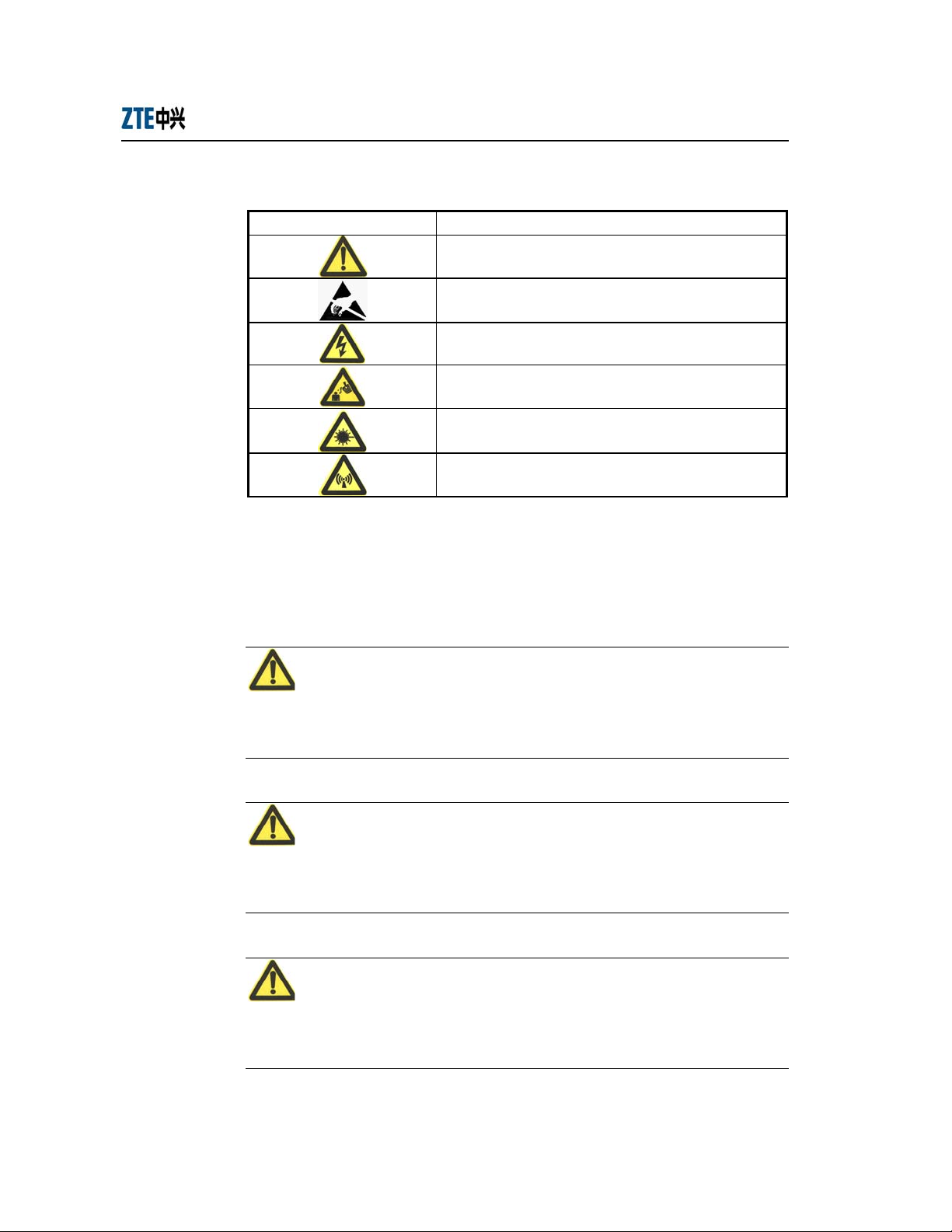
Table 1.2-1 Safety Symbols and Descriptions
Safety Symbol Meaning
Call for notice
Call for antistatic measures
Warn against electric shock
Caution against scald
Warn against laser
Caution against microwave
Four types of safety levels are available: danger, warning, caution and note. To the
right of a safety symbol is the text description of its safety level. Under the symbol is
the detailed description about its contents. The formats are as follows.
Danger:
Indicates an imminently hazardous situation which, if not avoided, will result in death
or serious injury. This signal word is to be limited to the most extreme situations.
Warning:
Indicates a potentially hazardous situation which, if not avoided, could result in death
or serious injury.
Caution:
Indicates a potentially hazardous situation which, if not avoided, could result in minor
or moderate injury. It may also be used to alert against unsafe practices.
1-2

Chapter Error! Style not defined. Error! Style not defined.
Note:
A Note statement is used to notify people of installation, operation, or maintenance
information that is important, but not hazard-related.
Tips:
Indicates a suggestion or hint to make things easier or more productive for the reader
1-3


2 Installation and Debugging
W140A require installation by professional installer. This chapter introduces the
W140A fittings, installation methods and steps, debugging methods and steps for your
reference.
2.1 Equipment Configurations and Fittings
2.1.1 Equipment Configurations
The W140A is composed of a kit and optional fittings. Items in the kit are not to be
changed randomly, but items in the fittings are dispensable depending on the user
demands.
Please refer to Table 2.1-1 for a list of the W140A kit.
Table 2.1-1 A List of the W140A Kit
Name Unit Quantity Remarks
W140A Set 1
Backplane PCS 1
Mounting panel PCS 1
Power over Ethernet (PoE)
product
Power cord of PoE product pc 1 1.5m
PoE cable pc 1 30m
Grounding cable pc 1 10m
Antenna feeder pc 1 1.2m
Set 1
With seven M8×10 inner hex head
screws and four expansion screws
2-1

ZXR10 WAS (V1.0) W140A Outdoor Wireless Access Point / Bridge
Professional Installation Instruction Manual
Please refer to Table 2.1-2 for a list of optional fittings of the W140A.
Table 2.1-2 A List of Optional Fittings of the W140A
Name Unit Quantity Remarks
Omni antenna pc 1 8 dBi omni antenna
Directional antenna pc 1 8.5 dBi directional antenna
Directional antenna pc 1 14 dBi directional antenna
Directional antenna pc 1 21 dBi directional antenna
Antenna kit Set 1 Used for installing and fixing an omni antenna.
Used for roof-mounted mode (comprising a vertical
Installing support A Set 1
Installing support B Set 1
Installing support C Set 1
Lightning arrester pc 1
pole), applicable to install all types of antennae, and
providing an installation position for a lightning
arrester.
Used for pole-mounted mode (excluding a vertical
pole), inapplicable to install a directional antenna,
and an installation position for a lightning arrester
not available.
Used for side wall-mounted mode (comprising a
vertical pole), applicable to install all types of
antennae, but an installation position for a lightning
arrester not available. You can choose roof-mounted
mode or side wall-mounted mode as required.
If a lightning arrester is not available on the roof,
you must install a lightning arrester in an installing
support A.
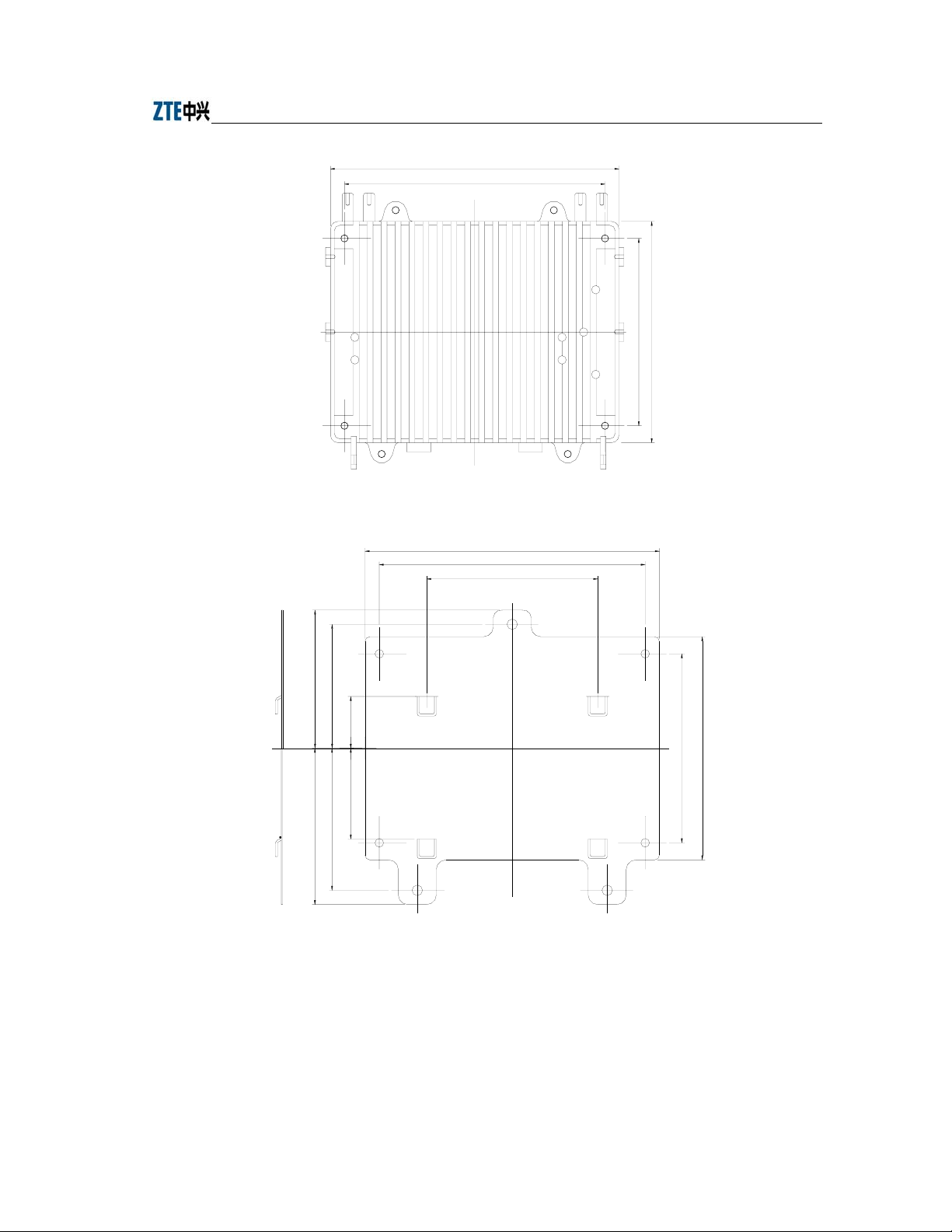
2.1.2 Mechanical Parts
Mechanical parts of the W140A consist of the W140A, backplane, mounting panel and
installation fittings. Fig. 2.1-1, Fig. 2.1-2 and Fig. 2.1-3 show the mechanical structures
of W140A, backplane and mounting panel in turn.
2-2
Chapter Error! Style not defined. Error! Style not defined.
310
280
Fig. 2.1-1 W140A Structure
310
280
180
9
5
9
3
1
2
5
.
5
4
5
1
.
0
3
1
5
.
4
5
9
5
9
3
1
2
5
.
5
9
5
.
9
5
.
4
4
1
6
1
Fig. 2.1-2 The Structure of W140A Backplane
2-3
ZXR10 WAS (V1.0) W140A Outdoor Wireless Access Point / Bridge
Professional Installation Instruction Manual
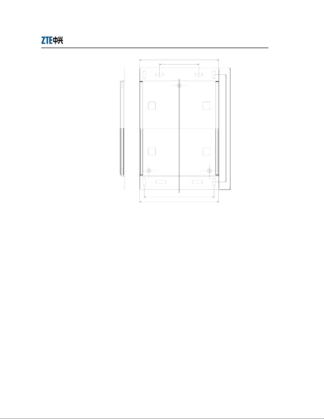
260
130
2
0
5
0
3
4
2.1.3 Antenna
230
260
Fig. 2.1-3 The Structure of W140A Mounting Panel
An antenna works effectively to convert high-frequency oscillating currents (energy)
into radio waves which are transmitted to the air; or, convert the radio waves received
from the air into high-frequency voltage (energy). It serves to implement energy
conversion.
The W140A adopts an outdoor antenna: Omni antenna or directional antenna.
Following are introductions to the common types of antennae.
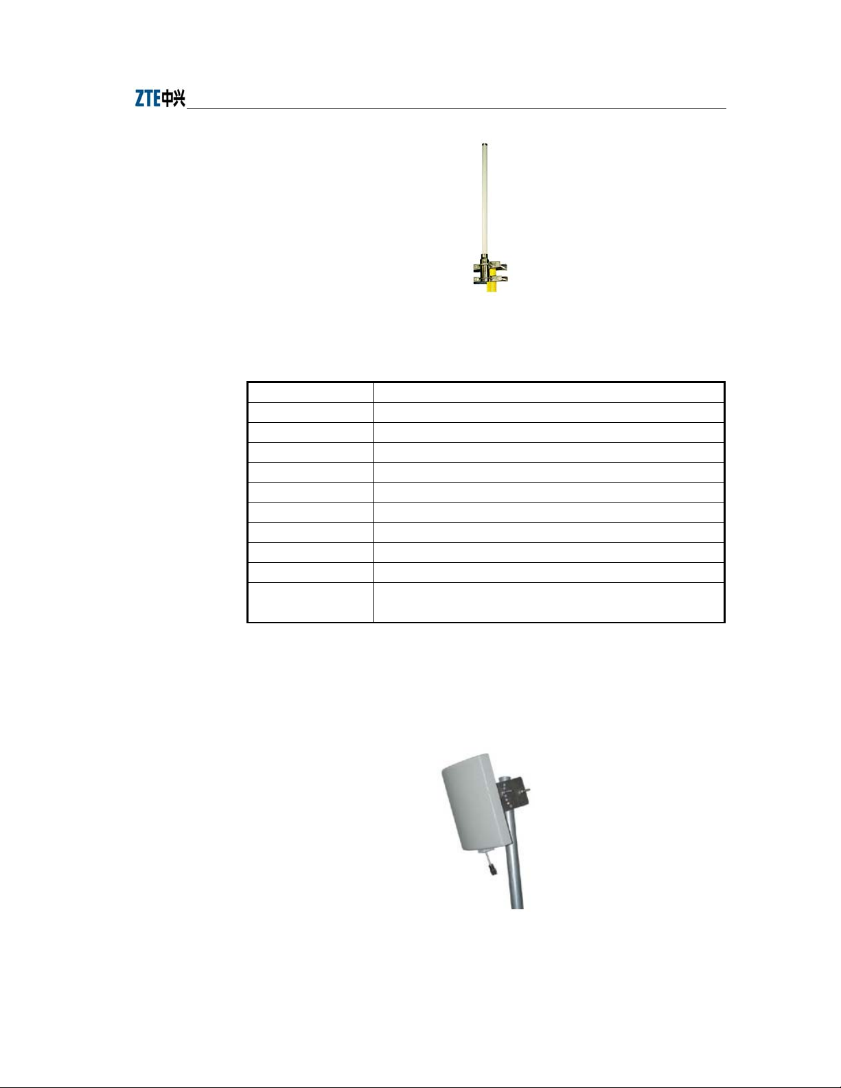
1. Outdoor omni antenna
Fig. 2.1-4 shows the physical appearance of an outdoor omni antenna, and Table
2.1-3 lists the technical indices.
2-4
Chapter Error! Style not defined. Error! Style not defined.
Fig. 2.1-4 Physical Appearance of an Omni Antenna
Table 2.1-3 Technical Indices of an Outdoor Omni Antenna
Items Technical Indices
Frequency range 2.4 GHz ~ 2.5 GHz
Gain 8 dBi
VSWR 1.5: 1 Max
Polarization Vertical polarization
Horizontal beam width 360°
Vertical beam width 15°
Connector type N-K
Input impedance 50 Ω
Outer dimensions φ 22 mm × 800 mm
Installation mode
The antenna is fixed to a pole through a fixture, and connected to the
antenna interface in the AP through a cable.
2. Indoor (outdoor) directional antenna
Fig. 2.1-5 shows the physical appearance of an indoor (outdoor) directional
antenna, and Table 2.1-4 lists the technical indices.
Fig. 2.1-5 Physical Appearance of an Indoor (Outdoor) Directional Antenna
2-5
ZXR10 WAS (V1.0) W140A Outdoor Wireless Access Point / Bridge
Professional Installation Instruction Manual
Table 2.1-4 Technical Indices of an Indoor (Outdoor) Directional Antenna
Items Technical Indices
Frequency range 2.4 GHz ~ 2.5 GHz
Gain 8.5 dBi
VSWR 1.5: 1 Max
Polarization Vertical polarization
Horizontal beam width 70°
Vertical beam width 65°
Connector type N-K
Input impedance 50 Ω
Outer dimensions 120 mm × 120 mm × 44 mm
The indoor or outdoor antenna is fixed to a wall or a pole through the
Installation mode
installation parts, and connected to the antenna interface in the AP
through a cable.
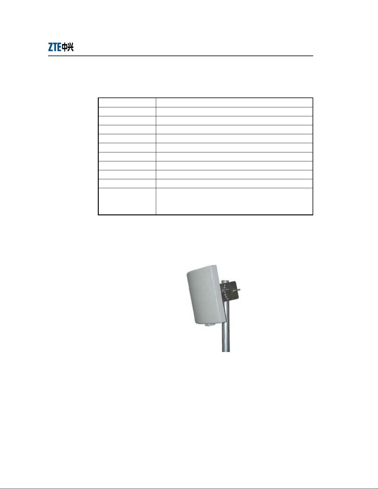
3. 14 dBi directional antenna
Fig. 2.1-6 shows the physical appearance of a 14 dBi directional antenna, and
Table 2.1-5 lists the technical indices.
Fig. 2.1-6 Physical Appearance of a 14 dBi Directional Antenna
2-6

Table 2.1-5 Technical Indices of a 14 dBi Directional Antenna
Items Technical Indices
Frequency range 2.4 GHz ~ 2.5 GHz
Gain 14 dBi
VSWR 1.5: 1 Max
Polarization Vertical polarization
Horizontal beam width 30°
Vertical beam width 30°
Connector type N-K
Input impedance: 50 Ω
Outer dimensions 240 mm × 240 mm × 60 mm
Installation mode
2.2 Installation Preparations
Whether the W140A is properly installed has a direct impact on the QoS of the system.
Due to the huge amount of installation work, it is necessary to work out a practicable
installation scheme to effectively ensure the progress and quality of the installation
work.
Chapter Error! Style not defined. Error! Style not defined.
The antenna is fixed to a support, and connected to the antenna interface
in the AP through a cable.
Complete the following issues before installing the W140A:
1. Network planning: Defining the installation location, installation mode and
connection method of the working ground.
2. Obtaining installation approval documents: To install the W140A in any public
building or the building of any group or individual, you should ask for
permission in advance.
3. Line resource: The W140A must be connected with the upper layer network
equipment via an RJ45 Ethernet interface. You should make sure beforehand
that whether the necessary line resource is available.
4. Lightning protection measures: Determining the lightning protection measures.
If a lightning arrester is to be installed, determining the grounding method of the
lightning protection grounding wire.
5. Installation personnel: Only the trained personnel should be allowed to install
the W140A, and supervision personnel should be present.
2-7
ZXR10 WAS (V1.0) W140A Outdoor Wireless Access Point / Bridge
6. Installation materials: Before the W140A is installed, making sure that all the
installation materials are ready.
7. The installation tools, instruments and documentations should be in place.
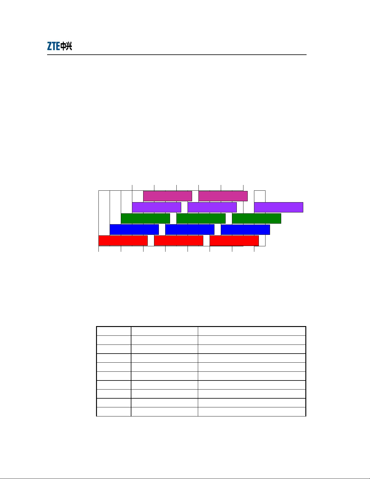
2.2.1 Channel Planning
According to the wireless LAN technology standard 802.11b and the standard of state
radio management committee, a wireless device in the wireless LAN operates at 2400
MHz ~ 2483.5 MHz, and the working frequency bandwidth is 83.5 MHz. The working
frequency is divided into 14 sub-channels, and the bandwidth of each sub-channel is 22
MHz. Fig. 2.2-1 shows the sub-channel allocations.
Professional Installation Instruction Manual
2.417 2.427 2.437 2.447 2.457
2.467
5 10
4
3
9
8
13
14
2 7 12
1 6 11
2.412 2.422 2.432 2.442 2.452 2.462 2.472 2.484
Fig. 2.2-1 Sub-channel Allocations
The above figure reveals that up to 13 channels are available. The IDs and central
frequencies of these 13 channels are described in Table 2.2-1.
Table 2.2-1 Channel IDs and Frequencies
Channel ID Central Frequency Low End/High End Frequency of the Channel
1 2,412 MHz 2401/2423 MHz
2 2,417 MHz 2411/2433 MHz
3 2,422 MHz 2416/2438 MHz
4 2,427 MHz 2421/2443 MHz
5 2,432 MHz 2426/2448 MHz
6 2,437 MHz 2431/2453 MHz
7 2,442 MHz 2431/2453 MHz
8 2,447 MHz 2436/2458 MHz
9 2,452 MHz 2441/2463 MHz
2-8
Chapter Error! Style not defined. Error! Style not defined.
10 2,457 MHz 2446/2468 MHz
11 2,462 MHz 2451/2473 MHz
12 2,467 MHz 2456/2478 MHz
13 2,472 MHz 2461/2483 MHz
When multiple channels are working at the same time, the central frequency intervals
between two channels should not be less than 25 MHz to avoid mutual interference. As
shown in Fig. 2.2-1, the technology of direct sequence spread spectrum can support
three un-overlapped channels working simultaneously in a cell.
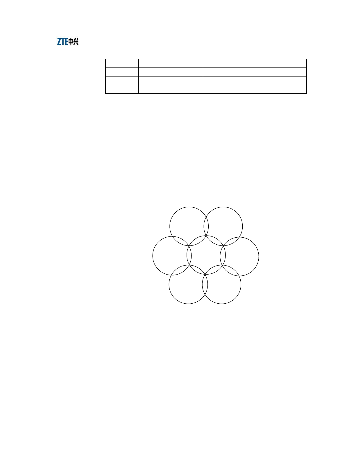
In the wireless LAN planning, the cellular coverage principle applied in the BTS
system is introduced in the channel allocation to ensure efficient coverage of the APs
and avoid inter-carrier interference. This principle supports three un-overlapped
channels (for example, channels 1, 6 and 11) working simultaneously in the same area,
as shown in Fig. 2.2-2.
AP
channel 11
Fig. 2.2-2 Channel Allocations between the Adjacent APs in Actual Networking
You should choose the working channels (generally channels 1, 6 and 11) for the
adjacent APs following the principle illustrated in Fig. 2.2-2, to guarantee normal
operation of the equipment in the wireless LAN.
2.2.2 Configurations Before Installation
Prior to install the W140A, power on the APs in turn and check whether they work
normally. If they fail to work normally, please check whether the versions are loaded
correctly. Refer to Section Error! Reference source not found. for details of loading a
2-9
AP
channel 6
AP
channel 6
AP
channel 1
channel 11
AP
channel 11
AP
channel 6
AP
 Loading...