

Page 1

Cable Modem/Router
with N600 Dual-band
Wireless
USER MANUAL
Page 2

NOTICE
This document contains proprietary information protected by copyright, and this Manual and all the
accompanying hardware, software, and documentation are copyrighted. No part of this document may
be photocopied or reproduced by mechanical, electronic, or other means in any form.
The manufacturer does not warrant that the hardware will work properly in all environments and
applications, and makes no warranty or representation, either expressed or implied, with respect to the
quality, performance, merchantability, or fitness for a particular purpose of the software or
documentation. The manufacturer reserves the right to make changes to the hardware, software, and
documentation without obligation to notify any person or organization of the revision or change.
All brand and product names are the trademarks of their respective owners.
© Copyright 2015 Zoom Telephonics, Inc.
All rights reserved.
Safety Issues & Warnings
SAFETY
This equipment is designed with the utmost care for the safety of those who install and
use it. However, special attention must be paid to the dangers of electric shock and static
electricity when working with electrical equipment. All guidelines of this and of the
computer manufacture must therefore be allowed at all times to ensure the safe use of
the equipment.
CAUTION:
• Do not put the cable modem in water.
• Do not use the cable modem outdoors.
• Keep the cable modem in an environment that is between 0°C and 40°C
(between 32°F and 104°F).
• Do not place any object on top of the cable modem since this may cause
overheating.
• Do not place the cable modem in a confined space that may cause overheating.
• Do not restrict the flow of air around the cable modem.
• Zoom Telephonics assumes no liability for damage caused by any improper use
of the cable modem.
2
Page 3

CONTENTS
GETTING STARTED 5
PackageContents ............................................................................................................................... 5
SystemRequirements ......................................................................................................................... 5
INSTALLING THE CABLE MODEM/ROUTER 7
Beforeinstallingyourcablemodem,pleasereadthis: ....................................................................... 7
Ifyouarereplacingan“old”cablemodem,dothis:........................................................................... 7
Ifthisisafirst‐timecablemodeminst allation(thatis,youareNOTreplacingan“old”cable
modem),dothis:................................................................................................................................. 9
HardwareConnection ....................................................................................................................... 12
CONNECTING OTHER DEVICES TO THE CABLE MODEM/ROUTER 15
EstablishingyourWirelessNetwork ................................................................................................. 16
ConnectingaWireless‐enabledDevice(includingtheiPhoneorothercellularphones,iPadorother
tablets,theiPodTouch,etc.)totheCableModem/Router............................................................... 17
ConnectingaWindows8.1or8ComputerwithBuilt‐inWirelessCapabilities ................................ 18
ConnectingaWindows7ComputerwithBuilt‐inWirelessCapabilities........................................... 19
ConnectingaWindowsVistaComputerwithBuilt‐inWirelessCapabilities .................................... 20
ConnectingaWindowsXPComputerwithBuilt‐inWirelessCapabilities......................................... 21
ConnectingaMacintoshOSXComputerwithBuilt‐inWirelessCapabilities.................................... 22
ConnectingaComputerwithaWirelessadaptertotheCableModem/Router ............................... 23
UsingWPSasanalternativewaytosetupyourWirelessNetwork................................................. 24
ConnectingAdditionalComputersand/orOtherDevicestotheCableModem/Router’s
Ethernet/LANports........................................................................................................................... 26
CHANGING THE DEFAULT WIRELESS SETTINGS 28
AboutWirelessSecurity .................................................................................................................... 28
ChangingyourWirelessNetworkName(SSID)andWirelessSecurityKey/Password ...................... 29
SettingUpSecurityUsingWEP ......................................................................................................... 30
DisablingSecurity ............................................................................................................................. 31
ONLINE GAMING 33
Gaming ............................................................................................................................................. 33
DMZHost..........................................................................................................................................34
PortTriggers ..................................................................................................................................... 35
ADVANCED SETTINGS 38
ChangingDefaultSettings ................................................................................................................ 38
AccessingtheZoomConfigurationManager.................................................................................... 39
UnderstandingtheConfigurationManagerInterfaceScreens ......................................................... 40
ConfigurationManagerInterfaceMenus ......................................................................................... 42
STATUS MENU OPTIONS 43
Software ........................................................................................................................................... 43
Connection............................................................................................................................... ......... 44
Security ............................................................................................................................................. 45
3
Page 4

TDiagnostics ..................................................................................................................................... 47
EventLog .......................................................................................................................................... 50
BASIC MENU OPTIONS 51
Setup................................................................................................................................................. 51
DHCP................................................................................................................................................. 54
DHCPv6 ............................................................................................................................................. 55
LANIPv6 ........................................................................................................................................... 56
DDNS................................................................................................................................................. 57
Backup/Restore................................................................................................................................. 59
ADVANCED MENU OPTIONS 61
Options ............................................................................................................................................. 61
IPFiltering......................................................................................................................................... 64
MACFiltering.................................................................................................................................... 65
PortFiltering..................................................................................................................................... 67
Forwarding ....................................................................................................................................... 68
PortTriggers ..................................................................................................................................... 70
DMZHost.......................................................................................................................................... 72
RIPSetup........................................................................................................................................... 73
FIREWALL MENU OPTIONS 76
Basic.................................................................................................................................................. 76
EventLog .......................................................................................................................................... 77
PARENTAL CONTROL MENU OPTIONS 82
Basic.................................................................................................................................................. 82
UserSetup............................................................................................................................... .......... 85
ToDFilter(TimeofDayFilter)........................................................................................................... 87
EventLog .......................................................................................................................................... 88
WIRELESS MENU OPTIONS 90
Radio................................................................................................................................................. 90
PrimaryNetwork .............................................................................................................................. 92
GuestNetwork.................................................................................................................................. 95
Advanced .......................................................................................................................................... 99
AccessControl................................................................................................................................. 101
WMM(Wi‐FiMultimedia) .............................................................................................................. 102
Bridging .......................................................................................................................................... 104
Media.............................................................................................................................................. 106
VPN (VIRTUAL PRIVATE NETWORK) MENU OPTIONS 108
BasicSetting ............................................................................................................................... .... 108
IPSec ............................................................................................................................................... 109
L2TP/PPTP ....................................................................................................................................... 115
EventLog ........................................................................................................................................ 117
APPENDIX A: TROUBLESHOOTING TIPS 119
APPENDIX B: IF YOU NEED HELP 124
APPENDIX C: COMPLIANCE 125
4
Page 5

1
Getting Started
This User Manual provides instructions for connecting and configuring your Cable
Modem/Router and for setting up wireless and wired connections to the cable modem.
This manual also includes details about security, firewalls, VPNs (Virtual Private
Networks) and administrative tasks.
Package Contents
Your package contains the following items:
• Cable Modem/Router
• Power cube
• Ethernet RJ-45 cable
• Quick Start flyer
System Requirements
• You need to connect the Cable Modem/Router to a cable modem service that uses
any of the popular DOCSIS standards – 3.0, 2.0, or 1.1. If you need to get cable
modem service, please speak with your cable service provider.
• To configure your modem, we recommend you use a computer with a built-in Ethernet
port if one is available. If one is not available, you can use a wireless device to
configure you modem.
You may have already used the Quick Start flyer to set up your Cable Modem/Router, to
establish an Internet connection, and perhaps to set up a local area network. If you did,
you may not need to read this User Manual. On the other hand, you may choose to
read this User Manual for topics not covered in the Quick Start or to make changes to the
settings you previously configured.
• If you haven’t already set up your Cable Modem/Router using the Quick Start, go
to
Chapter 2: Installing the Cable Modem/Router.
• If you have already installed your cable modem and want to learn more about
connecting both wired and wireless computers and other devices to your Cable
5
Page 6

Modem/Router, go to: Chapter 3: Connecting Other Devices to your Cable
Modem/Router.
• Your Cable Modem/Router comes from the factory with a default SSID (Wireless
Network Name), wireless security enabled, and a unique random Wireless
Security Key (Wireless Password). These default settings for your modem/router
are listed on the label of your cable modem/router. When the cable modem is
standing vertically this label is located on the side of your modem. Most users can
simply use the default settings. You may want to change the wireless settings if
you are replacing a wireless router and want to use the same wireless network
name and wireless password as the existing router instead of changing all your
wireless devices to use the Cable Modem/Router’s defaults, or in the unlikely
event that one of the wireless devices only supports WEP security. If you want to
make changes to the default wireless settings, please refer to
Chapter 4:
Changing your Wireless Settings.
• We strongly recommend that you change the default password in the
Configuration Manager for your Cable Modem/Router. (This is not the Wireless
Password.) This precaution, recommended for any router, helps prevent a CSRF
(cross site request forgery) hacker from gaining control of your router and
redirecting you to websites that they control to steal sensitive financial
information or money from you. To learn how to change this default password,
please see
Accessing the Zoom Configuration Manager.
• If you are using the Cable Modem/Router for online gaming and need to make
changes to the router’s firewall, please see
Chapter 5: Online Gaming.
• If you are like most users, you will not need to make changes to the Cable
Modem/Router’s advanced settings. If your setup requires you to make changes
to advanced settings, go to
Chapter 6: Advanced Settings.
6
Page 7

2
Installing the Cable Modem/Router
This chapter provides basic instructions for connecting the hardware and configuring the Cable
Modem/Router using the Zoom Configuration Manager. This chapter is almost identical to the
printed Quick Start.
We strongly recommend that you stand the cable modem up, with the logo toward the
top. Standing the modem up will normally give you better wireless reception and improve
modem cooling. Please rotate the base so it supports the modem case. After you
stand your cable modem up, remember to adjust your antennas for best reception –
normally with each one pointing up and away from the other antenna.
Before installing your cable modem, please read this:
You need to connect the cable modem to a cable modem service that uses any of the
popular DOCSIS standards – 3.0, 2.0, or 1.1. If you need to get cable modem service,
please speak with your cable service provider.
Your cable service provider will need to know your modem's MAC ADDRESS and the
account number of your cable service. The MAC ADDRESS is printed on a label on
your modem. When the cable modem is standing vertically this label is located on the
side of your modem. Your account number can be found on your bill, or you can call
your service provider and ask them for your account number. You need to provide this
information when you order cable modem service, or when calling the cable company
after installing your modem, or when filling out the account setup web page that may
appear when you first connect your cable modem to your provider’s network. You may
also be asked for your cable modem's model name and number, which is ZOOM 5360.
If you need the modem's serial number, you can find it near the MAC address on the
label.
If you are replacing an “old” cable modem, do this:
7
Page 8

1 Disconnect the coaxial cable from the old cable modem and connect it to your
Zoom modem. If the coaxial cable has a screw-on connector, turn the connector
clockwise when tightening the cable onto the Zoom cable modem.
2 If there’s an Ethernet cable plugged into the old cable modem, unplug the
Ethernet cable from the old cable modem and plug it into any of the Zoom cable
modem’s yellow LAN jacks.
3 Connect the Zoom power cube between the Zoom cable modem and a live
power jack. DO NOT use your old cable modem’s power cube on your Zoom
cable modem.
4 It normally takes 5 to 30 minutes to establish an Internet link the first time a Cable
Modem/Router connects to a cable service provider. This allows the cable
modem to connect to the appropriate channels for communication. You’ll see the
DS, US, and/or Online modem lights on your cable modem flashing until the
Online light stays steady green to signal success.
After the cable modem connects to your cable service provider, open your Web
browser on the computer that’s connected to your cable modem/router. Then
refresh the screen or try to go to a Web site. Many service providers, including
Comcast, typically bring your browser to a registration page. In that case, follow
the instructions on this registration page to register your modem. (Comcast
Users Only: If the activation page does not appear, please go to
www.comcast.com/activate to activate your modem.)
If no registration page appears after following the browser instructions above,
you need to call your cable company to register your modem. Below is a list of
some major cable service providers’ phone numbers to call if you need to
activate your cable modem. Note that this list is subject to change.
Comcast 1 (855) 652-3446 Time Warner 1 (855) 704-4503
RCN 1 (866) 832-4726 Cable One 1 (877) 692-2253
Cox 1 (888) 556-1193
Once your cable modem is registered either online or through a conversation
with someone at your cable service provider, your service provider will provision
your cable modem service. Typically this takes less than 5 minutes, but in some
cases this may take up to 30 minutes to complete.
5 Go toNow that your cable modem is connected, do this:below.
8
Page 9
If this is a first-time cable modem installation (that is, you are NOT replacing an “old” cable modem), do this:
1 Connect a “live” coaxial cable from your cable service provider to your cable
modem First check that the wire in the center of the cable’s connector is
centered, straight, and clean. If the coaxial cable has a screw-on connector, turn
the connector clockwise when tightening the cable onto the Zoom cable modem..
(If you’re not sure a cable is live, you can see whether you get a good TV signal
when that cable is used with a working TV set-top box.) Here are some ways
you can get the live cable:
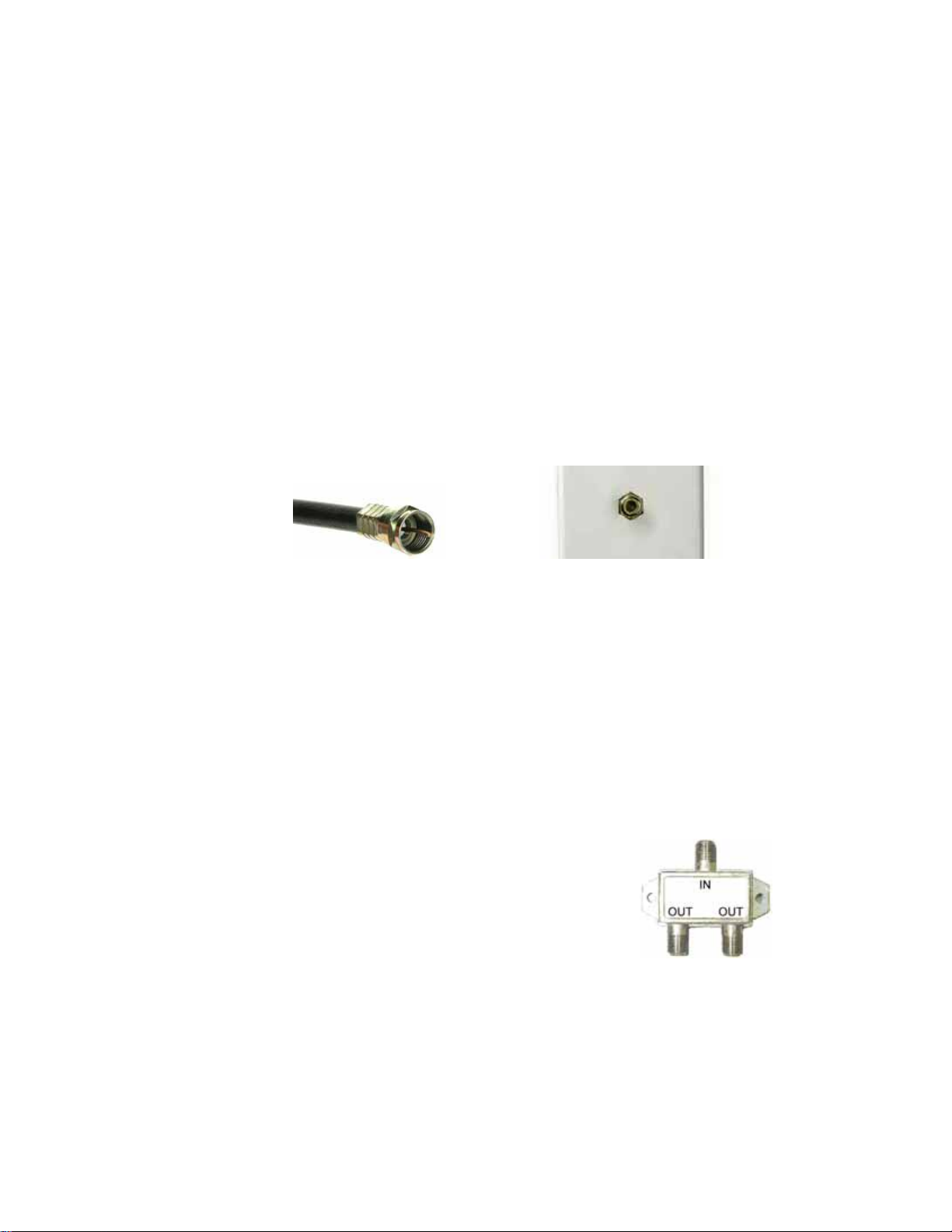
Coaxial Cable Cable TV Jack
¾ You have a cable TV cable (“coaxial cable”) with a male connector on the end
that isn’t connected to anything. This cable may be coming out of a wall or
connected to a cable TV jack.
¾ There’s a cable TV jack in your wall. You can connect a cable TV “coaxial
cable” between that jack and your cable modem. You may have a coaxial
cable, possibly one that came with a cable modem starter kit from your cable
service provider. If you don’t have a coaxial cable, you can get one at most
electronics stores. You want one with a screw-in male F connector at each
end, with a length that works for your installation.
¾ If you don’t have an available cable TV cable or wall
jack, use a coaxial “T adapter” or “splitter” available
from most electronics retailers (see example at right).
Make sure you get one designed for cable modems
and/or cable TV. These typically have one female
IN jack and two female OUT jacks. You can
disconnect a live cable from your TV set-top box and
screw it into the IN jack of the splitter. Then connect one coaxial cable from
an OUT jack to your TV set-top box and another coaxial cable from the other
OUT jack to your cable modem. You can see that this approach uses one
9
Page 10

splitter and 2 additional coaxial cables, each of which has male connectors
on each end. Some electronics retailers carry the Zoom Cable Modem
Connection Kit which has an excellent splitter and 2 coaxial cables packaged
together at a reasonable price. You can also purchase splitters and coaxial
cable separately if you prefer to do that, perhaps because you need a special
length of coaxial cable.
2 Connect the supplied Ethernet cable between any cable modem LAN jack and a
computer’s Ethernet jack. We recommend that you do this even if you later plan
to disconnect this computer. If connecting the Ethernet cable to a computer is
difficult or impossible, you can make a wireless connection to the Cable
Modem/Router. Please see,
Chapter 3: Connecting Other Devices to your
Cable Modem/Router for details on establishing a wireless connection.
3 Connect the Zoom power cube between the Zoom cable modem and a live
power jack.
4 It normally takes 5 to 30 minutes to establish an Internet link the first time a Cable
Modem/Router connects to a cable service provider. This allows the cable
modem to connect to the appropriate channels for communication. You’ll see the
DS, US, and/or Online modem lights on your cable modem flashing until the
Online light stays steady green to signal success.
After the cable modem connects to your cable service provider, open your Web
browser on the computer that’s connected to your cable modem/router. Then
refresh the screen or try to go to a Web site. Many service providers, including
Comcast, typically bring your browser to a registration page. In that case, follow
the instructions on this registration page to register your modem. (Comcast
Users Only: If the activation page does not appear, please go to
www.comcast.com/activate to activate your modem.)
If no registration page appears after following the instructions above, you need
to call your cable company to register your modem. Below is a list of some major
cable service providers’ phone numbers to call to activate your cable modem.
Note that this list is subject to change.
Comcast 1 (855) 652-3446 Time Warner 1 (855) 704-4503
RCN 1 (866) 832-4726 Cable One 1 (877) 692-2253
Cox 1 (888) 556-1193
Once your cable modem is registered either online or through a conversation with
someone at your cable service provider, your service provider will provision your
10
Page 11

cable modem service. Typically this takes less than 5 minutes, but in some cases
this may take up to 30 minutes to complete.
5 Go to Now that your cable modem is connected, do this: below.
Now that your cable modem is connected, do this:
Now that you have installed your cable modem and it has synchronized itself with the
cable network, your cable modem can connect your computers, tablets, smartphones
and other Wi-Fi compatible or Ethernet-enabled devices to the Internet.
To check that your cable modem is working, open your browser and go to a familiar Web
site. If it works, congratulations! Installation is complete for a single PC.
• To learn how to connect both wired and wireless computers and other devices to
your Cable Modem/Router go to:
Cable Modem/Router.
• Your Cable Modem/Router comes from the factory with a default SSID (Wireless
Network Name), wireless security enabled, and a unique random Pre-Shared
Key (Security Key/Password). These default settings for your modem/router are
listed on the label of your unit. When the cable modem is standing vertically this
label is located on the side of your modem. Most users can go ahead and use the
default settings. You may want to change the wireless settings if you are
replacing a wireless router and want to use the same wireless network name and
wireless password as the existing router instead of changing all your wireless
devices to use the Cable Modem/Router’s defaults, or in the unlikely event that
one of the wireless devices only supports WEP security. If you want to make
changes to the default wireless settings, please refer to
your Wireless Settings.
• We strongly recommend that you change the default password in the
Configuration Manager for your Cable Modem/Router. (This is not the Wireless
Password.) This precaution, recommended for any router, helps prevent a
CSRF (cross site request forgery) hacker from gaining control of your router and
redirecting you to websites that they control to steal sensitive financial
information or money from you. To learn how to change your default password,
please see
Accessing the Zoom Configuration Manager.
• If you are using the Cable Modem/Router for online gaming you may need to
Chapter 3: Connecting Other Devices to your
Chapter 4: Changing
11
Page 12
make changes to the router’s firewall please see Chapter 5: Online Gaming.
• If you are like most users you will not need to make changes to the Cable
Modem/Router’s advanced settings. If your setup requires you to make changes
go to
Chapter 6: Advanced Settings.
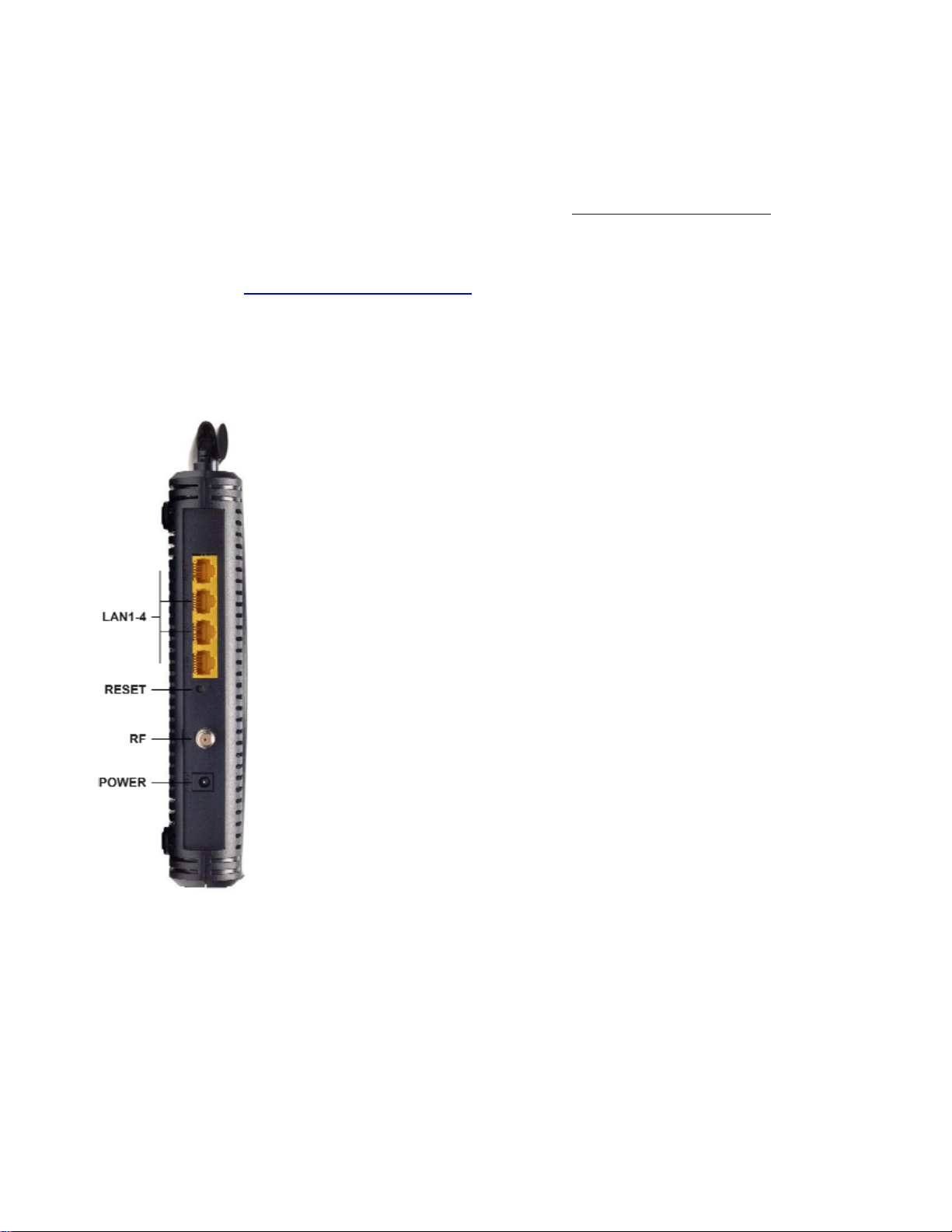
Hardware Connection
LAN 1-4
(Gigabit Ethernet 1-4)
RESET Press and hold this recessed button at least 8
RF
POWER
Four 10/100/1000 auto-sensing Ethernet ports
for computers and other devices that have an
Ethernet port
seconds in the unlikely event that you want to
restore the default factory settings. This button is
recessed to prevent accidental resets of your
cable modem/router.
Connect your coaxial cable line to this port.
Connect the supplied power cube to this port.
Front Panel LEDs
12
Page 13

Your Zoom cable modem has several lights on its front panel to help you monitor
the Cable Modem/Router’s status.
LIGHT COLOR DESCRIPTION
Power is supplied to the cable
modem/router
Power is not supplied to the cable
modem/router
Scanning for DS channel
Synchronized on 1 channel
only
Negotiating bonded
channel(s)*
Bonded with 2 or more
channels
Ranging is in progress
Ranging is complete; operate
Power
DS
Downstream
sync
Green
Green or
Blue
ON:
OFF:
Green Blinking:
Green ON:
Blue Blinking:
Blue ON:
Green Blinking:
Green ON:
on 1 channel
US
Upstream sync
Online
Green or
Blue
Green
Blue Blinking:
Blue ON:
O FF:
Blinking:
ON:
O FF:
Blinking:
Negotiating bonded
channel(s)*
Bonded with 2 or more
channels
Upstream channel is inactive
Cable interface is acquiring IP, Time
of Day, and configuration
Cable modem/router is online
Cable modem/router is offline
Data is flowing and Ethernet is
connected
LAN 1-4
Ethernet LAN
ports
Green or
Amber
Green:
Amber:
O FF:
Connected at highest LAN speed, 1
Gbps
Connected at 10 or 100 Mbps
No Ethernet link detected
Blinking: Data is flowing and wireless is
2.4G
Green
ON: 2.4 GHz wireless band is enabled
connected on the 2.4 GHz band.
OFF: 2.4 GHz wireless band is not
enabled
13
Page 14

Blinking: Data is flowing and wireless is
5G
Green
ON: 5 GHz wireless band is enabled
connected on the
5 GHz band
O FF: 5 GHz wireless band is not enabled
Blinking: WPS is in discovery mode (LED
blinks for up to 2 minutes)
ON: LED lit solid after WPS configuration
WPS
Green
is successful
OFF: (after 2 minutes blinking): No Wi-Fi
client associated with the cable
modem/router via WPS
WPS
Button
Pressing the WPS button for 5 seconds
initiates a WPS connection with other wireless
devices.
*If Blue light blinks continuously, this indicates partial service (at least one designated
channel has not completed bonding). This does not generally affect performance, but
your cable company may want to know so they can adjust their network
.
14
Page 15
3
Connecting Other Devices to the Cable
Modem/Router
This chapter explains how to connect devices (computers, phones, tablets, game
stations, etc.) to the Cable Modem/Router. These devices can be connected either
wirelessly or to one of the Ethernet ports on your Cable Modem/Router.
If you are connecting a computer or other device to an Ethernet LAN port of the Cable
Modem/Router, please go to
the Cable Modem/Router’s Ethernet/LAN ports. If you are connecting one or more Wi-Fi
compatible devices wirelessly to the cable modem/router, please continue below.
Connecting Wi-Fi compatible wireless devices to your Cable
Modem/Router
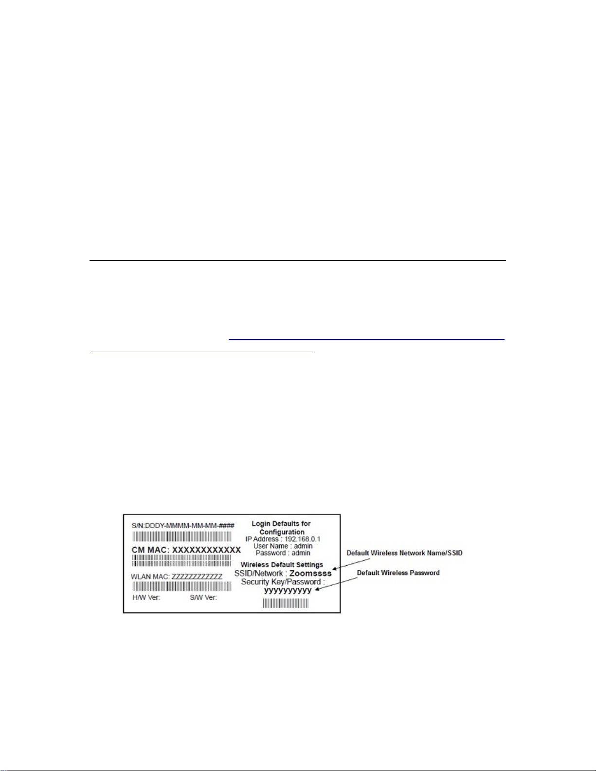
Your Cable Modem/Router comes pre-configured with these wireless settings:
• WPA2-PSK/WPA-PSK security is enabled
• A random Pre-Shared Key (also called a security key or password) that’s unique
for your modem/router. The Security Key/Password is printed on the label of
your cable modem/router. When the cable modem is standing up, this label is
located on the side of your modem.
Cable Modem label:
Connecting Additional Computers and/or Other Devices to
• The default SSID (wireless network name) is assigned as Zoomxxxx (where
15
Page 16

xxxx are the 4 last digit of the CM MAC Address). The SSID name on the label is
for model 5360’s 2.4 GHz frequency band. Model 5360’s 5 GHz band has the
same name plus -5G at the end, and is only visible if your wireless device works
at 5 GHz.
Your Cable Modem/Router is capable of sending and receiving wireless data on both the
2.4GHz frequency band and the 5 GHz frequency band at the same time. Almost all
computers, smartphones, tablets, and other client devices support the 2.4 GHz band,
and some also support the 5 GHz band. A major advantage of the 5 GHz band is that it’s
normally much less crowded with other devices trying to use that band. This is especially
important in areas with lots of wireless devices, such as some cities. To select the 5 GHz
network for a client device, pick the network ending in 5G. You may want to try both
SSIDs to see which one gives you better speed and range.
Most users should simply use these default settings. If you want to change these default
settings please see,
connecting your wireless computers or devices.
You must use compatible wireless settings for each computer or device that you want to
wirelessly connect to the Cable Modem/Router, as described below.
Chapter 4, Changing the Default Wireless Settings before
Establishing your Wireless Network
If all the computers or devices on your network support WPS, you can use WPS to easily
set up your network. Windows 8.1, 8, and 7 support WPS. Non Windows devices
typically have a button called WPS on them if they support WPS. (Note: Apple iPads,
iPhones, and Macintosh computers do not support WPS as of July 2015.) Please see
Using WPS to set up your Wireless network if you want to use WPS for wireless
connections to your Cable Modem/Router.
If some of the wireless devices do not support WPS, or if you do not know whether they
do support WPS, you can configure each computer or device manually. To do that,
select one of the possibilities for that computer or other device below:
¾ If you have a non-computer wireless device like an iPhone or other cellular
phone, iPad or other tablet, iPod Touch, etc., see the instructions on page 17 for
Connecting a Wireless-enabled Device to your Cable Modem/Router.
¾ Many newer Windows 8.1, 8, 7, Vista, and XP computers have built-in wireless
networking capabilities and do not require the installation of a wireless component.
16
Page 17

If this is the case, you should set up that computer’s wireless connection using the
Windows 8.1 or 8, 7, Vista, or XP connect utility. See the sections below on
connecting
(page 21) computers with built-in wireless capabilities.
¾ If you are using a Macintosh computer see the instructions on page 22 for
Connecting a Macintosh OS X Computer with Built-in Wireless Capabilities
¾ Some older Windows computers may have built-in wireless networking capabilities,
but not use the Windows 8.1, 8, 7, Vista, or XP utility to configure wireless networking. If
this is so, set up your computer’s wireless connection using the instructions on page 23
for
Connecting a Computer with a wireless adapter to the Cable Modem/Router.
¾ Some computers may need a wireless network adapter installed. This can be a USB
adapter, PC Card adapter, or PCI adapter. When you install the adapter, make sure that it
is set to infrastructure or access point mode (NOT ad-hoc or peer-to-peer mode). If
you need help installing your wireless adapter or setting its mode, refer to the
documentation that came with it. After you install the adapter, see the instructions on
page 23 for
Windows 8.1 or 8 (page 18), Windows 7 (page 19), Vista (page 20), or XP
Connecting a Computer with a wireless adapter to the Cable Modem/Router.
Connecting a Wireless-enabled Device (including the iPhone or other cellular phones, iPad or other tablets, the iPod Touch, etc.) to the Cable Modem/Router
1 Select the wireless-enabled computer or device t hat you want to add to th e network.
The device should have software that will let it perform a site search to scan for
available wireless networks in your area. You may have to click on something like
Settings and then Wi-Fi. When the list of available wireless networks appears, click
on Zoomxxxx-5G to connect to your Cable Modem/Router’s 5 GHz network. If you
do not see Zoomxxxx-5G then most likely your wireless adapter does not support
the 5 GHz network, so click on Zoomxxxx. In both cases, xxxx are the last 4 digits
of the CM MAC address. You can find Zoomxxxx printed on the label of your Cable
Modem/Router. In the unlikely event that you changed the SSID from the default,
select your new SSID.
2 When prompted for the wireless password, enter your Pre-Shared Key (Security
Key/Password) and click either Next, Connect or Join. Y our Security Key/Password
can be found on the label of your Cable Modem/Router.
Tip!
If you need help, refer to the documentation that came with your wireless device.
17
Page 18

3 Test your wireless connection. Open your device’s Web browser (for instance,
Internet Explorer, Firefox, or Chrome) and try to connect to a familiar Web address. If
you are unable to connect, make sure you followed the instructions. If you did,
please see
Your device is now connected to your wireless network. If you want to connect additional
computers or devices, follow the instructions for your device by starting at the first page
of this chapter.
Appendix A: Troubleshooting Tips.
To disconnect from the current network:
1 On your wireless device or computer, find the wireless network connection option
(similar to the process of adding your device or computer to the network).
2 Click or highlight your SSID (wireless network name).
3 Select or click on Disconnect, Forget, or Forget this network or similarly-named
button
.
Connecting a Windows 8.1 or 8 Computer with Built-in Wireless Capabilities
1 Click the Wireless Network Configuration utility icon in your computer’s
system tray.
2 Typically you then click on Zoomxxxx-5G to connect to your Cable Modem/Router’s
5 GHz network. If you do not see Zoomxxxx-5G then most likely your wireless
adapter does not support the 5 GHz network, so click on Zoomxxxx. In both cases,
xxxx are the last 4 digits of the CM MAC address. You can find Zoomxxxx printed on
the label of your Cable Modem/Router. In the unlikely event that you changed the
SSID from the default, select your new SSID.
3 Click Connect. If you want to connect to this network automatically in the future,
check the Connect Automatically checkbox.
4 When prompted to enter your Network Security Key, enter your Pre-Shared Key
(Security Key/Password) and hit Next. Your Security Key/Password can be found on
the label of your Cable Modem/Router.
5 When asked “Do you want to turn on sharing between PCs and connect to devices
on this network?” Click Yes to enable sharing and No to disable sharing. Sharing
sets up your firewall to allow other users on your network to share files, folders or
18
Page 19

devices such as printers. Most users should select Yes. If you know you don’t want
to share files or devices, select No.
6 Test your wireless connection. Open your computer’s Web browser and try to
connect to a familiar Website. If you are unable to connect, make sure you followed
the instructions. If you did, please see
Your computer is now connected to your wireless network. If you want to connect
additional computers or devices, follow the instructions for your device by starting at the
first page of this chapter.
Appendix A: Troubleshooting Tips.
To disconnect from the current wireless network:
1 Left-click the wireless network icon in the notification area of the Windows taskbar.
2 Right-click your SSID (wireless network name) and select Disconnect.
Connecting a Windows 7 Computer with Built-in Wireless Capabilities
1 Click the Wireless Network Configuration utility icon in your computer’s
system tray.
2 Typically you then click on Zoomxxxx-5G to connect to your Cable Modem/Router’s
5 GHz network. If you do not see Zoomxxxx-5G then most likely your wireless
adapter does not support the 5 GHz network, so click on Zoomxxxx. In both cases,
xxxx are the last 4 digits of the CM MAC address. You can find Zoomxxxx printed on
the label of your Cable Modem/Router. In the unlikely event that you changed the
SSID from the default, select your new SSID.
3 Click Connect. If you want to connect to this network automatically in the future,
check the Connect Automatically checkbox.
4 When prompted to enter your Network Security Key, enter your Pre-Shared Key
(Security Key/Password) and hit OK. Your Security Key/Password can be found on
the label of your Cable Modem/Router.
5 Test your wireless connection. Open your computer’s Web browser and try to
connect to a familiar Website. If you are unable to connect, make sure you followed
the instructions. If you did, please see
Your computer is now connected to your wireless network. If you want to connect
additional computers or devices, follow the instructions for your device by starting at the
first page of this chapter.
Appendix A: Troubleshooting Tips
19
Page 20

To disconnect from the current network:
1 Right-click the wireless network ico n in the notif ication area of the Windows taskbar.
2 Right-click your SSID (wireless network name) and select Disconnect.
Connecting a Windows Vista Computer with Built-in Wireless Capabilities
1 From the Start menu select Connect to.
2 In the Connect to a network dialog box, typically you click on Zoomxxxx-5G to
connect to your Cable Modem/Router’s 5 GHz network. If you do not see
Zoomxxxx-5G then most likely your wireless adapter does not support the 5 GHz
network, so click on Zoomxxxx. In both cases, xxxx are the last 4 digits of the CM
MAC address. You can find Zoomxxxx printed on the label of your Cable
Modem/Router. In the unlikely event that you changed the SSID from the default,
select your new SSID.
3 Click Connect. If you want to connect to this network automatically in the future,
check the Connect Automatically checkbox.
4 When prompted to enter your Network Security Key, enter your Pre-Shared Key
(Security Key/Password) and hit Connect. Your Security Key/Password can be
found on the label of your Cable Modem/Router.
5 In the Successfully connected to [desired network] dialog box, you have three
options. You can:
• Select Save the network and Start this connection automatically if you
always want to connect to the same network. Then click Close. The next time
you start your computer, you will automatically connect to the selected network.
• Select Save the network and clear the Start this connection automatically
check box if you don't want to automatically connect to this network every time
you start your computer but you will want to sometimes connect to this wireless
network in the future. Click Close to display the Select a location . . . dialog box
where you choose a location. Windows Vista automatically applies the correct
network security settings. If the User Account Control dialog box appears, click
Continue.
• Click Close to complete the connection procedure. Select this option if you are
connecting to this network only one time.
20
Page 21

5 Test your wireless connection. Open your computer’s Web browser and try to
connect to a familiar Website. If you are unable to connect, make sure you followed
the instructions. If you did, please see
Your computer is now connected to your wireless network. If you want to connect
additional computers or devices, follow the instructions for your device by starting at the
first page of this chapter.
Appendix A: Troubleshooting Tips.
To disconnect from the current network:
1 From the Start menu, select Connect to.
2 In the Disconnect or Connect to another network dialog box, select the current
network and click Disconnect.
3 In the Are You Sure? message box, click Disconnect again.
4 In the next dialog box, you can connect to anoth er network or click Close to complete
the disconnect procedure.
Connecting a Windows XP Computer with Built-in Wireless Capabilities
1 On your Windows desktop, click the Wireless Network Icon in the System Tray.
2 Typically you then click on Zoomxxxx-5G to connect to your Cable Modem/Router’s
5 GHz network. If you do not see Zoomxxxx-5G then most likely your wireless
adapter does not support the 5 GHz network, so click on Zoomxxxx. In both cases,
xxxx are the last 4 digits of the CM MAC address. You can find Zoomxxxx printed on
the label of your Cable Modem/Router. In the unlikely event that you changed the
SSID from the default, select your new SSID.
3 Click Connect. If you want to connect to this network automatically in the future,
check the Connect Automatically checkbox.
4 When prompted to enter your Network Security Key, enter your Pre-Shared Key
(Security Key/Password) and hit Connect. Your Security Key/Password can be
found on the label of your Cable Modem/Router.
5 Test your wireless connection. Open your computer’s Web browser and try to
connect to a familiar Website. If you are unable to connect, make sure you followed
the instructions. If you did, please see
Appendix A: Troubleshooting Tips.
21
Page 22
Your computer is now connected to your wireless network. If you want to connect
additional computers or devices, follow the instructions for your device by starting at the
first page of this chapter.
To disconnect from the current network:
1 On your Windows desktop, click the Wireless Network Icon in the System Tray.
2 Click View Wireless Networks button.
3 Select your SSID (wireless security name) and click Disconnect.
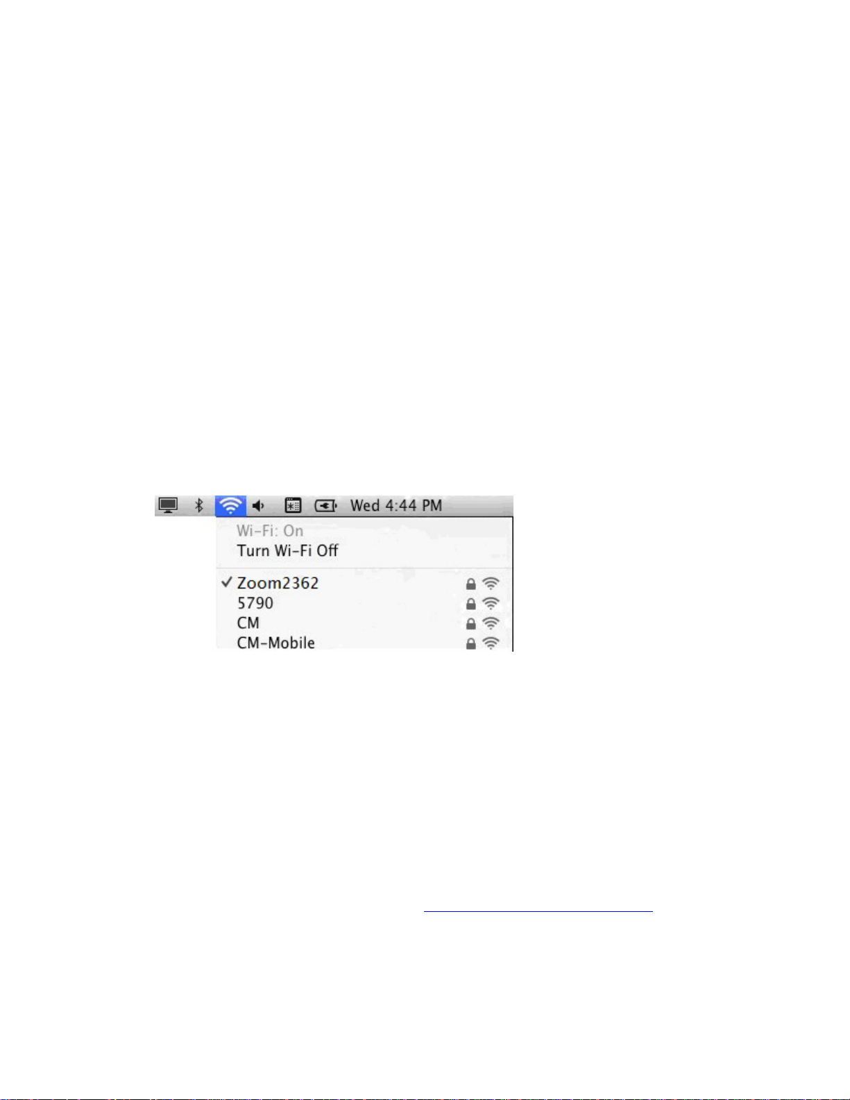
Connecting a Macintosh OS X Computer with Built-in Wireless Capabilities
1 Click the Wi-Fi icon in the menu bar. If the Wi-Fi icon does not appear on your menu
bar, please refer to your built-in Macintosh documentation for how to enable wireless.
Note: On versions prior to OS 10.7 the Wi-Fi icon is called AirPort.
2 Typically you then click on Zoomxxxx-5G to connect to your Cable Modem/Router’s
5 GHz network. If you do not see Zoomxxxx-5G then most likely your wireless
adapter does not support the 5 GHz network, so click on Zoomxxxx. In both cases,
xxxx are the last 4 digits of the CM MAC address. You can find Zoomxxxx printed on
the label of your Cable Modem/Router. In the unlikely event that you changed the
SSID from the default, select your new SSID.
3 When prompted for the password in the next dialog box, enter your Pre-Shared Key
(Security Key/Password) and hit Join. Your Security Key/Password can be found on
the label of your Cable Modem/Router.
4 Test your wireless connection. Open your computer’s Web browser and try to
connect to a familiar Website. If you are unable to connect, make sure you followed
the instructions. If you did, please see
Appendix A: Troubleshooting Tips.
22
Page 23

Your computer is now connected to your wireless network. If you want to connect
additional computers or devices, follow the instructions for your device by starting at the
first page of this chapter.
To disconnect from the current network:
1 Click the Wi-Fi icon on the menu bar.
2 Select Turn Wi-Fi Off (OS 10.7 or later) or Turn AirPort Off (OS versions prior to
10.7) to disconnect from the router.
Connecting a Computer with a Wireless adapter to the Cable Modem/Router
1 Go to the computer that is set up with a wireless adapter that you want to add to the
network. For many wireless adapters, you will use their configuration manager
software and click a Scan button or select a Site Scan, Scan Networks, or other
similarly named tab to do a site search. When the list of available wireless networks
appear, you typically select Zoomxxxx-5G to connect to your Cable
Modem/Router’s 5 GHz network. If you do not see Zoomxxxx-5G then most likely
your wireless adapter does not support the 5 GHz network, so click on Zoomxxxx. In
both cases, xxxx are the last 4 digits of the CM MAC address. You can find
Zoomxxxx printed on the label of your Cable Modem/Router. In the unlikely event
that you changed the SSID from the default, select your new SSID.
If you need help, refer to the documentation that came with your wireless adapter.
Note for Windows 8.1, 8, 7, Vista and XP users: If you installed a wireless adapter
on a Windows 8.1, 8
configure the adapter (rather than let you use the software provided with the wireless
adapter). You will know this is happening because you will be prompted with a
message about one or more wireless networks being available. You will also be able
to click a link to open the Wireless Network Connection Properties dialog box. If
this happens, click the link, clear the Use Windows to configure my wireless
network settings check box, and then click OK. You can then use the software
provided with your wireless adapter without interruption from Windows.
2 When prompted for the wireless password, enter your Security Key/Password and
hit Connect. Your Security Key/Password can be found on the label of your Cable
Modem/Router.
, 7, Vista or XP computer, Windows may try to automatically
23
Page 24

3 Test your wireless connection. Open your device’s Web browser (for instance,
Internet Explorer, Firefox, or Chrome) and try to connect to a familiar Web address. If
you are unable to connect, make sure you followed the instructions. If you did,
please see
Your device is now connected to your wireless network. If you want to connect additional
computers or devices, follow the instructions for your device by starting at the first page
of this chapter.
Appendix A: Troubleshooting Tips.
To disconnect from the current network:
1 On your computer that has a wireless adapter, find the wireless network connection
option (similar to the process of adding your computer to the network).
2 Click or highlight the Router’s Wireless Security Name.
3 Select or click on Disconnect or similarly-named button.
Using WPS as an alternative way to set up your Wireless Network
If all the Wi-Fi compatible wireless devices on your network support WPS, you can
choose to quickly setup your wireless network by pushing a button on your cable
modem/router and on each wireless device connecting to your cable modem/router.
Windows 8.1, 8 and Windows 7 users should follow the instructions below: Other
computers or devices such as tablets should go to
computer or other device that supports WPS.
If you are using a Windows 8.1, 8 or 7, computer:
1 Open Connect to a Network on that computer by right-clicking the network icon in
the notification area of the Windows taskbar.
2 A list of available networks is displayed.
3 Typically you then click on Zoomxxxx-5G to connect to your Cable Modem/Router’s
5 GHz network. If you do not see Zoomxxxx-5G then most likely your wireless
adapter does not support the 5 GHz network, so click on Zoomxxxx. In both cases,
xxxx are the last 4 digits of the CM MAC address. You can find Zoomxxxx printed on
the label of your Cable Modem/Router. In the unlikely event that you changed the
SSID from the default, select your new SSID.
If you are using a non Windows
4 You will see a screen with a text box for the Security key. If WPS configuration is
supported, you may see a message such as You can also connect by pushing the
24
Page 25
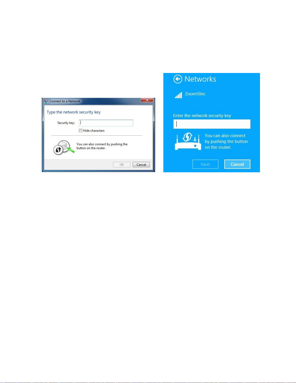
button on the router. If you see this message, continue at step 5 below.
Windows 7
Windows 8.1 or 8
5 Press the Wi-Fi Protected Setup (WPS) button on the router for at least 3 seconds.
(You do not need to type a security key or passphrase in the Security key text box on
your Windows machine). The Cable Modem/Router will automatically set up the
computer to connect to the network and apply the network's security settings. Then
click OK on the computer’s Connect to a Network dialog box.
Repeat steps 1-5 above for each Windows computer you want to connect to the Cable
Modem/Router. If you want to connect a non Windows computer or another device
such as a tablet, follow the instructions below.
If you are using a non Windows computer or other device that supports WPS
Please refer to the instructions for your device for more information on using WPS. The
directions below should work for most users.
1 Press the WPS button on the front panel of the router for at least 5 seconds. The
WPS LED should blink green.
2 Within 2 minutes (before the WPS LED light turns off), press the WPS button on the
device that you’re linking wirelessly to the modem/router. The button may be a
25
Page 26

physical pushbutton on the device or a button on a page of the device’s wireless
network configuration menus.
3 Congratulations! You should now have a secure connection between your Cable
Modem/Router and a device. Now is a good time to check that your device’s Internet
connection is working. Open your browser and go to a familiar Web site. If you are
able to connect, continue with the next step below.
If you are not able to connect to the Internet, please see
Troubleshooting Tips.
4 If you have other devices whose WPS security you need to set, repeat steps 1
through 3 for each device. When they are finished, the basic setup for these local
wireless devices should be complete
.
Appendix A:
Connecting Additional Computers and/or Other Devices to the Cable Modem/Router’s Ethernet/LAN ports
You can plug up to four computers, game consoles, or other Ethernet-capable devices into the
Cable Mo dem/Route r’s LAN po rts. For information about your specific device, please refer
to the documentation that came with that device. Follow the instructions below for each
computer or other device.
1 If you connected the Cable Modem/Router to a computer using a wired connection
when setting up the Cable Modem/Router, unplug the computer now if you don’t
want that computer to stay connected to the Cable Modem/Router.
2 To connect a computer or other Ethernet-capable device, plug one end of an
Ethernet cable into an available Ethernet (LAN 1, 2, 3, or 4) port on the Cable
Modem/Router and plug the other end of the Ethernet cable into the Ethernet port of
the additional device you want to connect to the Cable Modem/Router. (If you are
connecting a hub or a switch, this is typically called an Uplink or Expansion port.) If
you are connecting a computer or game station, go to step 5 of this section.
3 If you are connecting a network device such as a switching hu b, use the in structions
that came with that device. Then reboot any computer that is part of your network.
For example, if you connected a switching hub, reboot any computer that will be
connected to that switching hub.
4 If you are connecting a HomePlug adapter pair with one adapter plugged into the
Cable Modem/Router and an AC outlet, and the other adapter plugged into a
computer, game station, or other device and an AC outlet, make those connections
and then go to step 5.
5 Verify that your Internet connection is working. Open a Web browser on each
computer that’s using your network and try to connect to a familiar Web address.
26
Page 27

6 Congratulations! You have connected an additional device to the Internet. You can
connect up to 4 Ethernet-capable devices to the Cable Modem/Router, following the
instructions above for each device by starting at step 2 of this section.
27
Page 28

4
Changing the Default Wireless Settings
Your Cable Modem/Router comes from the factory with a default SSID (Wireless
Network Name), WPA-PSK/WPA2-PSK wireless security and a random Wireless
Security Key (Wireless Password). These default settings for your router are listed on the
label of your unit. When the cable modem is standing vertically this label is located on the
side of your modem. Most should use the default settings.
You may want to change your wireless settings if the wireless devices on your network
are already configured to use an existing wireless network name and password. Instead
of having to reconfigure all the devices on your network, you can change the Cable
Modem/Router to match the existing settings used by your devices. Read this chapter if
you want to use another wireless security mode, or if you want to change either the SSID
or Wireless Security Key. If you want to use the default wireless settings, you can skip
this chapter.
About Wireless Security
There are two basic wireless security modes, WPA and WEP. There are two versions of
WPA: WPA and WPA2. When configured as part of a typical home or small office
network, WPA and WPA2 require a Pre-Shared Key, or PSK. These modes are typically
called WPA-PSK and WPA2-PSK, respectively, though sometimes they’re just called
WPA and WPA2. You can enable either WPA-PSK or WPA2-PSK alone, or you can
enable both WPA-PSK and WPA2-PSK together. By default, your Cable Modem/Router
has both WPA-PSK and WPA2-PSK enabled. You will only need to change the security
mode if you know that you have a device you are connecting to your wireless network
that only supports WEP. (Go to
that you want an unsecured network, this is discussed late in this chapter in Disabling
Security.
Note: If you have a Radius Server (very unlikely for a home network), select the
WPA/WPA2 options without PSK. All instances of WPA and/or WPA2 that follow refer to
WPA-PSK and/or WPA2-PSK unless noted otherwise.
Setting Up Security Using WEP.) In the unlikely event
28
Page 29

You can check to see if all other clients that you plan to put on the network support WPA
or WPA2. You can do this by checking the manual that came with each device or by
checking the configuration software for the installed device. Look under Security or
Encryption or Setup or Advanced Features. Most devices will support one of these
modes.
• To change the Wireless Network Name (SSID) or Wireless Security
Key/Password (Pre-Shared key) used by your Cable Modem/Router go to
Changing your Wireless Network Name(SSID) and Pre-Shared Key.
• If any of the devices you want to connect to your wireless network do not support
WPA or WPA2, go to
Setting Up Security Using WEP.
• If you need to set up an unsecured network, see Disabling Security.
Changing your Wireless Network Name(SSID) and Wireless Security Key/Password
Most likely your previous wireless network used 2.4GHz. If you want to change your
Cable Modem/Router settings to match your existing network settings follow the steps
below. If you have devices that support 5GHz then you should connect to the Cable
Modem/Router’s 5G network. For instructions on connecting to the 5G network refer to
Chapter 3, Connecting other Devices to the Cable Modem/Router.
To check if your device supports the 5 GHz, you can scan for available wireless networks
on your device. If you see a wireless network named Zoomxxxx-5G than your devices
supports 5 GHz and you should follow the instructions for connecting that device to the
Cable Modem/Router found in Chapter 3. If you only see Zoomxxxx then your device
does not support 5 GHz. In both cases, xxxx are the last 4 digits of the CM MAC address.
You can find Zoomxxxx printed on the label of your Cable Modem/Router. When the
cable modem is standing vertically this label is located on the side of your modem.
1 Open the Zoom Configuration Manager by typing the following in your Web browser's
address bar:
2 In the Login dialog box, type the User Name and Password in lower case, then click
Login. (Here we assume the default User Name and Password.)
http://192.168.0.1
User Name: admin
Password: admin
29
Page 30

3 Click Wireless on the top menu.
4 The Wireless Radio page appears. Under Select 2.4 or 5 GHz option. Select 2.4 GHz
if your existing wireless network used 802.11n 2.4GHz. If your existing network used
802.11n 5GHz or you just want to change the SSID for the 5 GHz network select 5
GHz. Click Apply.
5 To change the wireless security, start by setting all the following drop-down menus to
Disable: WPA, WPA-PSK, WPA2, and WPA2-PSK.
6 Then select Enable for the mode(s) you choose for setting wireless security.
Note: To use WPA2 /WPA, all of the wireless devices on your network must support
either encryption method. In this case, enable:
o WPA-PSK and WPA2-PSK (if you want to use a Pre-Shared Key)
or
o WPA and WPA2 (use this only if your network uses a Radius Server. This
is very uncommon for a home network)
If you know that all your devices support the more secure WPA2 you can enable
WPA2 only (or WPA2-PSK if you want to use a Pre-Shared Key) instead of WPA and
WPA2.
7 In the WPA Pre-Shared Key text box (only if you selected an option requiring a
Pre-Shared Key), enter a passphrase of your choice (a minimum of 8 characters).
Write down this passphrase and put it where you can find it – on the bottom of the
Cable Modem/Router case, for instance.
8 Click Apply.
9 Now you need to set up each of your wireless devices with the SSID and passphrase
See Chapter 3, Connecting other Devices to the Cable Modem/Router for help on
connecting your wireless computers and devices.
Your security setup configuration is now complete!
Setting Up Security Using WEP
WEP is an older wireless security standard that has been shown to be easily defeated.
Because of this, the use of WEP has been phased out of use by the wireless industry a nd
should only be used if any when one of your network devices DOES NOT support WPA
or WPA2. WEP can be configured two ways: 64-bit and 128-bit. 128-bit WEP provides
more security than 64-bit.
1 Open the Zoom Configuration Manager by typing the following in your Web browser's
address bar:
http://192.168.0.1
.
30
Page 31

2 In the Login dialog box, type the User Name and Password in lower case, then click
Login. (Here we assume the default User Name and Password.)
User Name: admin
Password: admin
3 Click Wireless on the top menu. Under Select 2.4 or 5 GHz option. Select 2.4 GHz.
4 Change the 802.11N Mode drop-down menu to off and click Apply
5 Then click Primary Network on the left-side menu.
6 To change the wireless security, start by setting all the following drop-down menus to
Disable: WPA, WPA-PSK, WPA2, and WPA2-PSK
7 From the WEP Encryption drop-down menu, select WEP-64 bit (or WEP-128 bit for
more security).
8 For Network Key 1, you can either enter your own WEP Key or you can have WEP
Keys generated.
If you are entering a network key of your choice, enter 26 hexadecimal digits for
128-bit encryption keys. Enter 10 hexadecimal digits for 64-bit encryption keys.
Otherwise, type something into the text box and click on Generate WEP Keys and
WEP Keys will automatically be generated for you.
Caution! Do not click Apply until you have entered WEP Keys.
9 Click Apply.
10 Now you need to set up each of your wireless devices with the SSID and
passphrase. See
for help on connecting your wireless computers and devices.
Your security setup configuration is now complete!
Chapter 3, Connecting other Devices to the Cable Modem/Router
Disabling Security
If for some reason you need to set up an unsecured network, you will need to disable the
default security that is currently set up for your Cable Modem/Router. Follow the
instructions below.
1 Open the Zoom Configuration Manager by typing the following in your Web browser's
address bar:
2 In the Login dialog box, type the User Name and Password in lower case, then click
Login. (Here we assume the default User Name and Password.)
http://192.168.0.1
User Name: admin
Password: admin
31
Page 32

3 Click Wireless on the top menu.
4 The Wireless Radio page appears. Under Select 2.4 or 5 GHz option, choose 5 GHz
and click Apply.
5 Then click Primary Network on the left-side menu.
6 Set all the following drop-down menus to Disable: WPA, WPA-PSK, WPA2, and
WPA2-PSK.
7 Click Apply.
8 Click Wireless Radio on the left-side menu. Under Select 2.4 or 5 GHz option,
choose 2.4 GHz and click Apply. Repeat steps 5-7 to disable security on the 2.4
GHz band.
That’s it! You have now disabled security.
32
Page 33

5
Online Gaming
Read this chapter if you are going to use your Cable Modem/Router for online gaming.
Some online games require you to make changes to your firewall. This chapter explains
the different ways you can modify the firewall to allow your online gaming system access.
Gaming
If you are using your router for gaming, you may need to make changes to the router’s
firewall setting for the game to work. This is done by setting up a DMZ or using Port
Triggering so that the Cable Modem/Router’s firewall won’t block the other players
from your system during your gaming. The main difference between the methods is the
amount of access someone has to your system.
A DMZ allows access on all ports of the computer. Because of this, DMZ's are less
secure and should be used with caution with your computer. However DMZ’s work well
with gaming stations since security is not as much of an issue for gaming stations as it is
for computers.
Port triggering works by sensing when data is sent out on a predetermined outgoing port
and then automatically opening up the corresponding incoming port(s). It will
automatically forward the traffic on the incoming port to the computer that accessed the
outgoing port. If your game uses one port to send outgoing data and a different port (or
ports) for incoming data, you may want to use port triggering. You do not need to know
the IP address of your gaming station to set up port triggering. You will need to know
which ports your game requires you to open. This information is usually available with
your gaming software or you should be able to find it by searching for it on the web.
• If you want to set up a DMZ for your gaming system, go to
• If you want to set up Port Triggering for your gaming system, go to
Triggering.
33
DMZ Host.
Port
Page 34

DMZ Host
The DMZ (De-militarized Zone) Host page allows you to configure a network device (e.g.
a PC or gaming system) to be visible directly to the Internet. This may be used if a game
doesn’t work with port triggers or if you are using a gaming system, where security is less
of a concern.
To set up a DMZ for your gaming system, you should first assign your gaming system a
static IP address. Normally the Cable Modem/Router handles assigning IP addresses
to the different devices on your network using DHCP. However DHCP does not
guarantee that your device will always get assigned the same IP address. The DMZ
needs to know the IP address of your gaming system to work, if the IP address changes
the DMZ will not work. Because your IP address could change over time you need to
assign a static IP on your gaming system. To setup a static IP address on your gaming
system, please refer to your gaming system’s documentation. If you no longer have the
documentation that came with your gaming system it usually can be found online.
When assigning a static IP address to your gaming system you should select an address
that is outside the IP addresses assigned by the Cable Modem/Router’s DHCP server.
By default the DHCP Server assigns addresses from 192.168.0.10 to 192.168.0.255.
We recommend using 192.168.0.5 as the static IP address for your gaming system.
To setup a DMZ for your gaming system:
1 Follow the instructions for your gaming system to assign a static IP address. We
recommend using 192.168.0.5.
2 Next access the Cable Modem/Routers configuration menu by launching a Web
browser on a computer that is directly connected to one of the router’s LAN ports.
3 In the browser address bar, type http://192.168.0.1 and press the Enter key.
4 In the Login screen, enter:
default username: admin
default password: admin
Both the username and password are case sensitive. The default username and
password are printed on the label of your unit. When the cable modem is standing
vertically this label is located on the side of your modem.
5 Click the Login button to access the Cable Modem/Router. The Status page
appears.
6 Click Advanced in the menu bar.
34
Page 35

7 Then click the DMZ Host submenu. The DMZ Host page appears:
8 Enter the last byte of the LAN IP address of the static IP address you assigned to
your gaming system. For example if you assigned 192.168.0.5 enter 5.
9 Click Apply.
Your gaming system should now work with all your online games.
Port Triggers
Port Triggering works by sensing when your game sends data out through a specific
port. The outgoing data signals the router to allow the incoming game traffic to be passed
through the firewall on the correct port. Since the ports are only open when you are
gaming, port triggering is a very secure method for online gaming.
To set up port triggering you need to know what ports your game is using and whether
they use TCP, UDP or both on those ports. Typically this should be included with your
gaming software. If it is not included, try entering the name of your gaming software
followed by “ports used”.
Some games use the same ports for both incoming and outgoing traffic, while other
games use different ports for incoming and outgoing traffic.
Below is an example of setting up the popular game, World of Warcraft for port triggering.
Looking online, we find that World of Warcraft uses the following ports: 1119-1120, 3724,
4000, 6112-6114, and 6881-6999. We can also find out that these ports are all TCP.
35
Page 36

In this case the same ports are used for both incoming and outgoing traffic, so we would
use the same ports as both the triggering port and the target port as shown below.
To setup port triggering for World of Warcraft:
1 Launch a Web browser.
2 In the browser address bar, type http://192.168.0.1 and press the Enter key.
3 In the Login screen, enter:
default username: admin
default password: admin
Both the username and password are case sensitive. The default username and
password are printed on the label of your unit. When the cable modem is standing
vertically this label is located on the side of your modem.
4 Click the Login button to access the Cable Modem/Router. The Status page
appears.
5 Click Advanced in the menu bar.
6 Then click the Port Triggers submenu. The Port Triggers page appears. Click
Create button to create rules.
7 We will need to setup 5 triggers for World of Warcraft. The first rule would cover
ports 1119-1120. Enter 1119 in the Trigger Start Port field and 1120 in the Trigger
36
Page 37

End Port field. Since these ports are used to send data both directions enter 1119 in
the Target Start Port and 1120 in the Target End Port.
8 Select TCP in the Protocol drop down menu since these ports use TCP.
9 Enter a name for this rule, for example WOW1. Click Enable then click Apply. Your
new rule will appear in the table.
10 Repeat steps 7-9 for the next rule. In this case only one port is used, 3724. Enter
3724 in the Trigger Start/End Port and Target Start/End Port fields.
11 Repeat steps 7-9 for the remaining ports that need to be opened. When you are
complete the table should look like this:
If your online game does not work and you are sure that you entered the correct ports
on the port triggering page, check to see if you have a firewall running on your
computer that is preventing you from playing your online game. This firewall may be
either the built-in Windows firewall or may be part of a third party security package
you are using on your computer. You will need to allow access through these
firewalls to be able to play your online game.
37
Page 38

6
Advanced Settings
Advanced Setup is primarily for technically advanced users. For most people, the
options that are set by default when the Cable Modem/Router is installed are sufficient.
However, those who want or need to change the default settings can do so using the
advanced setup pages in the Zoom Configuration Manager.
This chapter includes:
• Suggestions for settings that you might want to change
• Instructions for launching the Zoom Configuration Manager program
• An overview of the available configuration menus and settings and a guide on
what chapter to go to for more information on each settings.
Changing Default Settings
Here are some reasons why you might want to use the Configuration program to change
the router's default settings.
•
Your Cable provider instructs you to enable, disable, or change the default settings
for your router
•
You want to change your router’s password to help prevent hacker attacks.
•
You want to set up a wireless guest network to give users access to the internet but
not your internal network.
•
You want to change the default firewall settings to block particular IP addresses and
intrusive hosts.
You want to access your corporate network and need to use the built-in VPN
•
function.
•
You wish to control the hours that a user on your network can access the Internet.
38
Page 39

Accessing the Zoom Configuration Manager
From your Web browser, you will log in to the interface to define system parameters,
change password settings, view status windows to monitor network conditions, and
control the Cable Modem/Router and its ports.
To access the Zoom Configuration Manager, use the following procedure:
1 Launch a Web browser.
Note: Your computer does not have to be online to configure your Cable
Modem/Router.
2 In the browser address bar, type http://192.168.0.1 and press the Enter key.
For example:
The Login screen appears (see
Figure 1)
Figure 1. Login Screen
3 In the Login screen, enter:
default username: admin
default password: admin
4 Click the Login button to access the Cable Modem/Router. The Status page
39
Page 40

appears, showing connection status information about your Cable Modem/Router
After you log in to the Zoom Configuration Manager interface, we strongly recommend
that you change the default password as follows:
1 On the left hand menu click on Security.
2 Enter admin in the User Name dialog box. The default user name can not be
changed
3 Enter the default password, admin in the Current Password dialog box.
4 Enter your new password in the New Password box. Your new password can be
from 1 to 8 characters long and can contain either letters or numbers. The
password and username are case sensitive, so notice which letters are capitalilzed.
5 In the Re-Enter New Password box enter your new password again and click
Apply. Your new password is now active. We recommend you write you new
password down on a label and attach it to your Cable Modem/Router. If you forget
your new password in the future, you can reset the Cable Modem/Router to its
default settings by pressing the Reset button for 8 seconds. This will change the login
back to the default User Name admin and the default password admin .
6 If you only wanted to change your password, you’re done. If you want to do
something else with the Configuration Manager, continue below to Understanding
the Configuration Manager Interface Screens.
Understanding the Configuration Manager Interface Screens
The top of the management interface contains a menu bar you use to select menus for
configuring the Cable Modem/Router. When you click a menu item, information and any
configuration settings associated with the menu appear in the main area of the interface
(see
Figure 2). If the displayed information exceeds what can be shown in the main area,
scroll bars appear to the right of the main area so you can scroll up and down through the
information.
40
Page 41

Figure 2. Main Areas on the Configuration Manager Interface
Every menu has submenus associated with it. If you click a menu item, the submenus
appear on the left frame of the Configuration Manager. For example, if you click the
Status menu item, the submenu Software, Connection, Security, Diagnostics, and
Event Log appear on the left column (see
Figure 3).
Figure 3. Example of Status Submenu
The right-most item on the menu bar is the logout option. Click it to log out from the
Configuration Manager interface.
41
Page 42

Configuration Manager Interface Menus
Table 1 describes the menus in the Configuration Manager interface. You can skip to
specific sections of this User Manual based on your intended use of the Cable
Modem/Router. Each of the menu options in your Configuration Manager is covered as a
separate chapter in the remaining portion of the User Manual. Refer to the chart on the
next page to go to a specific menu option
T
able 1. Configuration Manager Interface Menus
Chapter
Menu
Options
8
Status
.
Go to this section if you
want to…
monitor or troubleshoot
problems with the Cable
Modem/Router
See Page
43
9
10
11
12
13
14
Basic
Advanced
Firewall
Parental
Control
Wireless
VPN
make some modifications
for more advanced uses
make use of advanced
router features supported
by the Cable
Modem/Router
configure the firewall
application to protect the
private LAN from attacks
from the WAN interface
configure access policies
or rules to specific network
devices based on the time
of day and Internet
contents
configure and use the
wireless features
supported by the Cable
Modem/Router
enable the VPN protocol
and configure IPSec
tunnels, L2TP and PPTP
server options
51
61
76
82
90
108
42
Page 43

8
Status Menu Options
The Status Menu lets you:
• View the status and connection information of the Cable Modem/Router
• Change the administrator password
• Use diagnostic tools for troubleshooting
Software
The Software page is a read-only screen that shows the Cable Modem/Router’s current
system software version. To access the Software page, click Status in the menu bar and
then click the Software submenu
describes the items you can select.
Figure 4 shows an example of the menu and Table 2
43
Page 44

Figure 4. Software Menu
Table 2. Software Menu Option
Option Description
Information
Status
Shows the information on the current system software.
Shows the system up time, network accessibility, and IP address of
the Cable Modem/Router.
Connection
The Connection page is a read-only screen that shows the status of steps in your Cable
Modem/Router registration process. It also shows your Cable Modem/Router’s upstream
and downstream channel status.
To access the Connection page, click Status in the menu bar and then click the
Connection submenu.
Figure 5 shows an example of the menu.
44
Page 45

Figure 5. Example of Connection Page
By default the router is configured to use Dual mode (or Dual Stack mode). Most users
should use this setting. However your provider may ask you to change the eRouter
Provisioning mode to eRoute_IPv4only mode or eRoute_IPv6only mode.
Security
The Security page allows you to configure access privileges, reboot and restore the
Cable Modem/Router to its factory defaults.
To access the Security page, click Status in the menu bar and then click the Security
45
Page 46

submenu. Figure 6 shows an example of the menu and Table 3 describes the items you
can select.
Figure 6. Example of Security Page
How to change the default password used to access your device:
1 Enter admin in the User Name dialog box. The default user name can not be
changed.
2 Enter the default password, admin in the Current Password dialog box.
3 Enter your new password in the New Password box. Your new password can be
from 1-8 characters long and can contain either letters or numbers.
4 Retype your new password and click Apply.
Your new password is now active. We recommend you write your new password down
on a label and attach it to your Cable Modem/Router. If you forget your new password in
the future you can reset the Cable Modem/Router to its default settings by pressing the
Reset button for 8 seconds. This will change the login back to the default User Name
admin and the default password admin.
To restore the Cable Modem/Router to factory defaults:
1 In the Security submenu, select the Yes button next to Restore Factory Defaults.
2 Click Apply.
3 The reboot is complete when the POWER LED stops blinking.
4 If the Login screen doesn’t reappear, click the Refresh link to log back in to the
Configuration Manager.
46
Page 47

Table 3. Security Menu Option
Option Description
User Name
Current Password
New Password
Re-Enter New
password
Reboot
Note: DO NOT restore factory defaults to any changes on this page.
Enter the User Name for the administrator.
Enter the existing security password. The password can be
found on the label of the unit. When the cable modem is
standing vertically this label is located on the side of your
modem.
Enter the new security password.
Re-enter (confirm) the new security password.
Click the Yes button next to reboot, then click Apply to reboot
the router.
Diagnostics
Note: Some software versions may not support this feature.
The Diagnostics page allows you to troubleshoot connectivity problems. Two utilities are
provided for troubleshooting network connectivity: Ping and Traceroute.
Ping allows you to check connectivity between the Cable Modem/Router and devices on
the LAN while Traceroute allows you to map the network path from the Cable
Modem/Router to a public host.
Selecting Traceroute from the drop-down Utility list will present alternate controls for the
Traceroute utility.
To access the Diagnostics page, click Status in the menu bar and then click the
Diagnostics submenu.
Figure 7 and Figure 8 show the examples of the menu and
47
Page 48

Table 4 describes the items you can select.
Figure 7. Example of Diagnostics - Ping Page
48
Page 49

Figure 8. Example of Diagnostics - Traceroute Page
To run either utility:
1 Select the utility from the Utility drop-down list.
2 Make any changes to the default parameters.
3 Select Start Test to begin. The window will automatically be refreshed as the results
are displayed in the Results table.
49
Page 50

Table 4. Diagnostics Menu Option
Option Description
Utility
Parameters
Start Test
Abort Test
Clear Results
Select the utility for troubleshooting.
Enter the required parameters to perform diagnostics.
Click this button to begin diagnostic after making any changes to the
default parameters.
Click this button to abort Ping diagnostics.
Click this button to clear the results table.
Event Log
The Event Log page is useful when you are working with your cable provider to debug
your Cable Modem/Router. Most users can ignore this page.
To access the Event Log page, click Status in the menu bar and then click the Event
Log submenu.
Figure 9. Example of Event Log Page shows an example of the page.
Figure 9. Example of Event Log Page
50
Page 51

9
Basic Menu Options
The Basic Menu lets you:
• Configure the basic settings of your Cable Modem/Router
• Configure DHCP server for the LAN
• Configure DDNS service
• Backup and restore of configuration settings
Setup
The Setup page allows you to configure the basic features of the Cable Modem/Router
related to your ISP’s connection.
To access the Setup page, click Basic in the menu bar and then click the Setup
submenu.
describes the items you can set.
Figure 10 shows an example of the menu and Table 5. Setup Menu Option
51
Page 52

Figure 10. Example of Setup Page
Table 5. Setup Menu Option
Option Description
LAN IPv6
Address
LAN IPv4
Address
WAN IPv6
Address
WAN IPv4
Address
Release and
Renew WAN
Lease button
LAN IPv6 address will appear here when connected to IPv6 service.
Set the base LAN IP for your private network. By default this is
192.168.0.1 There is normally no need to change this.
WAN IPv6 address will appear here when connected to IPv6
service.
WAN IPv4 address will appear here when connected to IPv4
service.
Click on Release WAN Lease button to release WAN address. Click
on Renew WAN Lease button to renew WAN address.
52
Page 53

WAN
Connection
Type
Select how your Cable Modem/Router obtains an IP address. The
options are via DHCP or manual configuration of a static IP address.
Unless you have arranged for a static IP address from your service
provider, you should leave this setting at its default, DHCP.
IPv4 MTU Size
By default is set to 0 which uses the default setting. Allows you to
select between 600 to 1500.
53
Page 54

DHCP
The DHCP page allows you to configure your Cable Modem/Router’s DHCP server.
To access the DHCP page:
1 Click Basic in the menu bar.
2 Then click the DHCP submenu.
Figure 11 shows an example of the menu and Table 6 describes the items you can
select.
Figure 11. Example of DHCP Page
In the unusual event that you have a separate DHCP server on your LAN, you can
disable the Cable Modem/Router’s DHCP server by selecting the No radio button. If you
do this, make sure the IP address assigned to the Cable Modem/Router is on the same
subnet as that of the external DHCP server, or you won’t be able to access the Cable
Modem/Router from the LAN. The base LAN IP address of the Cable Modem/Router can
be set from the Basic Setup page.
Note that the Cable Modem/Router will only operate on a class C subnet, with subnet
mask 255.255.255.0
You may also want to disable the DHCP server if you have assigned static IP addresses
to all devices on your network.
54
Page 55

Table 6. DHCP Menu Options
Option Description
DHCP Server
Starting Local
Address
Number of
CPEs
Lease Time
Select Yes to use internal DHCP server of the Cable Modem/Router,
or select No to disable it.
Configure the starting IP address for IP leases available to devices
on the LAN.
Configure the number of PCs supported on the LAN.
Configure the time a lease will last before it must be renewed.
Default is 86400 seconds, or 1 day.
DHCPv6
The DHCPv6 page allows you to configure an internal DHCPv6 server for your network.
To access the DHCPv6 page:
1 Click Basic in the menu bar.
2 Then click the DHCPv6 submenu.
Figure 12. Example of DHCPv6 Page shows an example of the menu and Table 7
DHCPv6 Menu Option
describes the items you can select.
Figure 12. Example of DHCPv6 Page
55
Page 56

Table 7 DHCPv6 Menu Option
Option Description
System
Delegated Prefix
User Defined
Prefix
LAN Delegated
Prefix
Start Address
Number of
Address
Valid Lifetime
Enable Rapid
Commit
Enable Unicast
Disable Stateless
DHCPv6
LAN IPv6
Enter the prefix for you IPv6 LAN network. For example enter
FE80::1 if you want to use a Link Local address
Check to enable System Delegated Prefix.
If using System Delegate Prefixes the LAN Delegated Prefix will
be automatically configured, otherwise enter your LAN delegated
Prefix.
The starting IP address for your network.
Number of address allowed by the server.
How long the address is valid.
Rapid commit is enabled by default. It allows the Cable
Modem/Router to configure clients with a 2 message exchange
(solicit and reply) instead of a normal 4 message exchange
(solicit, advertise, request and reply). This helps to reduce traffic
on your network. Most users should use the default setting.
Most users can safely ignore this setting. Enabling unicast allows
you to talk to only one node on the network.
Click to disable Stateless DHCPv6.
The LAN IPv6 page displays information about .
To access the LAN IPv6 page:
3 Click Basic in the menu bar.
4 Then click the LAN IPv6 submenu.
Figure 13. Example of LAN IPv6 Page shows an example of the page and Table 8 LAN
IPv6 Option
describes the items on the page.
56
Page 57

Figure 13. Example of LAN IPv6 Page
Table 8 LAN IPv6 Option
Option Description
IP Address
MAC Address
Reachability
State
The IP address of devices on your network
The MAC address of the device.
Tells you the state of the device with this IP address.
DDNS
The DDNS page allows you to make use of a DDNS server. Dynamic DNS (DDNS)
allows a dynamic IP address to be aliased to a static, pre-defined host name so that the
host can be easily contacted by other hosts on the internet even if its IP address
changes. This means you can host a server on your LAN that can be accessed from
anywhere on the Internet.
Caution: Some service providers may consider connection of such a server to be a
breach of your service agreement.
The Cable Modem/Router supports a dynamic DNS client compatible with the Dynamic
57
Page 58

DNS service (http://www.dyndns.com/). You must sign up with this service if you want to
use it.
To access the DDNS page:
5 Click Basic in the menu bar.
6 Then click the DDNS submenu.
Figure 14 shows an example of the menu and Table 7 describes the items you can
select.
Figure 14. Example of DDNS Page
To activate the DDNS client:
1 Go to the DynDNS website and create an account for the Dynamic DNS service.
2 You will create a username and password, and be asked to choose a host name
for your server, and the dynamic DNS domain to which your host will be assigned.
3 You will also be asked for your host’s current IP address. This is the WAN IP
address that has been assigned to your Cable Modem/Router during provisioning.
(See WAN IP Address on the Basic / Setup web page.)
4 Enter your account information on the Basic / DDNS web page, enable the service by
selecting www.DynDNS.org from the DDNS Service drop-down list, and click Apply.
5 The DDNS client will notify the DDNS service whenever the WAN IP address
changes so that your chosen host name will be resolved properly by inquiring hosts.
58
Page 59

The current status of the service is shown at the bottom of the DDNS web page.
Table 9. DDNS Menu Option
Option Description
DDNS Service
User Name
Password
Host Name
IP Address
Status
Select the type of service that you are registered for from your
DDNS service provider.
Enter your DDNS account username subscribed to the service
provider.
Enter the password of the account.
Enter the host name of your service host.
Shows the current WAN side public IP address.
Shows the status of DDNS service.
Backup/Restore
Note: Some software versions may not support this feature.
The Backup page allows you to save the current Cable Modem/Router configuration
settings to a local PC. You can then later restore these settings if you need restore a
particular configuration, or to recover from changes you may have made that have had
an undesirable effect.
To backup the current configuration:
Click Backup and follow the prompts.
To restore a previous configuration:
Click Browse and use the navigation window to locate the file. (Usually
GatewaySettings.bin, unless you rename it before saving.) Once the file has been
located, click Restore to restore the settings.
Note: Once the settings are restored, the device will reboot.
To access the Backup page:
1 Click Basic in the menu bar.
2 Then click the Backup/Restore submenu.
59
Page 60

Figure 15 shows an example of the menu.
Figure 15. Example of Backup Page
60
Page 61

10
Advanced Menu Options
The Advanced Menu lets you:
• Enable advanced features of the Cable Modem/Router
• Configure LAN IP address, MAC address, and port number filtering
• Configure WAN to LAN port forwarding and triggers
• Configure DMZ hosting
• Configure RIP parameters
Options
The Options page allows you to configure the Cable Modem/Router to operate in
different modes that adjust how the device routes IP traffic.
To access the Options page:
1 Click Advanced in the menu bar.
2 Then click the Options submenu.
Figure 16 shows an example of the menu and Table 8 describes the items you can
select.
61
Page 62

Figure 16. Example of Options Page
62
Page 63

To enable a feature:
1 Click the appropriate check box (a check mark will appear).
2 When you are done with your selections, click on the Apply button.
Table 10. Options Menu Option
Option Description
Prevents the Cable Modem/Router or the PCs from responding to
WAN Blocking
pings to the Cable Modem/Router’s WAN IP address or to the
devices behind it. This makes it more difficult for hackers to attack
your PCs and other devices on your network.
IPSec/PPTP
PassThrough
Remote
Configuration
Management
Multicast
Enable
UPnP Enable
Primary
Network
Bridged
NAT ALG
Status
Enable to support VPN devices or software on your network.
Allows the Cable Modem/Router to be remotely administered at
port 8080. When enabled, navigate to http://CMIPAddress:8080/ to
administer the Cable Modem/Router remotely). You can find your
CM: WAN IP address on the
Basic Setup page.
Allows multicast specific traffic (denoted by a multicast specific
address) to be passed to and from the PCs on the private network
behind the Cable Modem/Router.
Select Enable to enable the UPnP agent in the Cable
Modem/Router. If you are running an application that requires
UPnP, check this box.
Allows all LAN hosts to bypass NAT and the Cable Modem/Router's
LAN DHCP Server. Adding MAC addresses into the table is not
required. If MAC addresses are added to the table then only those
MAC addresses in the list will bypass NAT and the LAN DHCP. All
other LAN hosts NOT in the list will use the NAT and LAN DHCP
Server as normal.
The NAT ALG section shows which ALGs (Application Layer
Gateway) are allowed to pass through the NAT Firewall. Most
users will not need to change these settings.
63
Page 64

IP Filtering
The IP Filtering page allows you to configure IP address filters in order to block specific
network devices on your LAN from accessing the Internet. By entering starting and
ending IP address ranges, you can configure which local PCs are denied access to the
WAN.
We recommend assigning a static IP address to your computer when using IP Filtering.
By default, the Cable Modem/Router uses DHCP to assign IP addresses. DHCP does
not guarantee that your computer will be assigned the same IP address. When assigning
a static IP address to your computer you should select an address that is outside the IP
addresses assigned by the Cable Modem/Router’s DHCP server. By default the DHCP
Server assigns addresses from 192.168.0.10 to 192.168.0.244. We recommend using
192.168.0.2 as the static IP address for your computer.
To access the IP Filtering page:
1 Click Advanced in the menu bar.
2 Then click the IP Filtering submenu.
Figure 17 shows an example of the menu and Table 9 describes the items you can
select.
Figure 17. Example of IP Filtering Page
64
Page 65

To activate the IP address filter:
1 Enter the last byte (the numbers after the last period) of the IP address in Start
Address and End Address.
2 Check the Enable box to the right of the entry to store settings.
3 Click the Apply button to activate the filter rules.
Table 11. IP Filtering Menu Option
Option Description
Start/End
Address
Enter the last byte of the IP address. The upper bytes of the IP
address are set automatically from the Cable Modem/Router IP
address.
To activate the IP address filter, you must also check the Enable box
Enable
and click Apply. You can disable this filter while retaining the
addresses you entered for later use.
MAC Filtering
The MAC Filtering page allows you to configure MAC address filters in order to block
Internet traffic to specific network devices on your LAN.
To access the MAC Filtering page:
1 Click Advanced in the menu bar.
2 Then click the MAC Filtering submenu.
Figure 18 shows an example of the menu and Table 10 describes the items you can
select.
65
Page 66

Figure 18. Example of MAC Filtering Page
Table 12. MAC Filtering Menu Option
Option Description
PCs and other devices can be added to the MAC filter table by
entering their MAC addresses into the Add MAC Address box, and
clicking the Add MAC Address button. Internet traffic to and from
MAC Address
each listed Address will be blocked.
The Mac Addresses of the computers attached to your network can
be found in the DHCP Clients table. To access the DHCP Clients
table click on Basic on the menu bar then DHCP.
66
Page 67

Port Filtering
The Port Filtering page allows you to configure port filters in order to block Internet traffic
to specific ports on all devices on your LAN.
Similarly, you can prevent PCs from sending outgoing TCP/UDP traffic to the Internet
from specific IP port numbers. This can be configured using the Port Filtering page.
To access the Port Filtering page:
1 Click Advanced in the menu bar.
2 Then click the Port Filtering submenu.
Figure 19 shows an example of the menu and Table 11 describes the items you can
select.
Figure 19. Example of Port Filtering Page
67
Page 68

For example, if you would like to block all PCs on the private LAN from accessing HTTP
sites (or “web surfing”):
1 Set the Start Port to 80, the End Port to 80.
2 Set the protocol to TCP.
3 Check the Enable box to the right of the entry to store settings.
4 Click Apply button to activate the filter rules.
Table 13. Port Filtering Menu Option
Option Description
Start/End Port
Protocol
Enters the start and end port of the port filter range
Filter either both TCP and UDP traffic or just UDP or just TCP.
Forwarding
The Forwarding page allows you to run a publicly accessible server from your LAN by
specifying the mapping of TCP/UDP ports to a local PC. It allows incoming requests to
specific port numbers to reach a web server, FTP server, mail server, etc.
To access the Forwarding page,
1 Click Advanced in the menu bar.
2 Then click the Forwarding submenu.
3 To add a new IPv4 rule, click on the Create IPv4 Rule button, to add a new IPv6 rule
click on the Create IPv6 Rule. Most users should select Create IPv4 rule unless
your LAN network is using IPv6.
Figure 20 shows an example of the menu and Table 12 describes the items you can
select.
68
Page 69

Figure 20. Example of Forwarding Page
To activate the port forwarding:
1 Enter the port range of the Internet traffic that you want to forward, and the IP
address of the server to which you want to forward that traffic.
2 Select the protocol(s) to be forwarded.
3 Check the Enable box to the bottom of the entry to store settings.
4 Click the Apply button to activate the forwarding rules.
Table 14. Forwarding Menu Option
Option Description
Enter the External IP address of the device that you want to allow
External IP
Address
access to your network. If you do not know the address you can
leave this field blank. Note: The External IP Address is not the CM
WAN IP address shown on the status page. It is the address of the
remote device.
External
Start/End Port
Local IP
Enter the range of port numbers (start and end port) from the
external device that you want to allow onto your network. If you do
not know the address you can leave this field blank
Enter the IP address to which forwarded traffic should be sent. If you
69
Page 70

Address
Start/End Port
are creating an IPv4 rule this should be an IPv4 address. If you are
creating an IPv6 rule this should be an IPv6 address.
Enter the range of port numbers (start and end port) to forward. If
only a single port is desired, enter the same port number in the Start
and End locations.
Protocol
Description
Enabled
Select the protocol(s) to be forwarded.
A brief description of the rule you have created.
Select ON to enable the rule. For security reasons you should leave
the rule disabled if you are not using it.
Note: You may need to assign static IP addresses to devices on your LAN to insure that
the port forwarding you have set up will always apply to them.
Port Triggers
The Port Triggers page allows you to configure dynamic triggers to specific devices on
the LAN. This allows for special applications that require specific port numbers with
bi-directional traffic to function properly. Applications such as video conferencing, voice,
gaming, and some messaging program features may require these special settings.
Port Triggers are similar to Port Forwarding except that they are not static ports held
open all the time. With the port triggering function, the Cable Modem/Router detects
outgoing data on a specific IP port number and opens corresponding target ports for
incoming data. If no outgoing traffic is detected on the Trigger Range ports for 10
minutes, the Target Range ports will close.
To access the Port Triggers page:
1 Click Advanced in the menu bar.
2 Then click the Port Triggers submenu.
3 To add a new Port Triggers rule, click on the Create button, to add a new rule.
Figure 21 shows an example of the menu and Table 13 describes the items you can
select.
70
Page 71

Figure 21. Example of port Triggers Page
To activate a port trigger
1 Enter the trigger and target ports range for the Internet traffic to forward to.
2 Select the forwarding protocol(s).
3 Enter a name for your port triggering rule.
4 Check the Enable box to the bottom of the entry to store settings.
5 Click the Apply button to activate the port trigger rules.
Table 15. Port Triggers Menu Option
Option Description
Trigger Range
(Start / End
Port)
Target Range
(Start / End
Port)
Protocol
Description
Enter the trigger range (starting and ending ports) of the application
for which you want to enable port triggering. The application will
send data from these ports.
Enter the target range (starting and ending ports) to open for the
same application. The application will receive data on these ports.
Select the protocol for this rule.
A brief description of the rule you have created.
71
Page 72

Enabled
Select ON to enable the rule. For security reasons you should leave
the rule disabled if you are not using it.
DMZ Host
The DMZ (De-militarized Zone) Host page allows you to configure a network device (e.g.
a PC) to be exposed or visible directly to the Internet. This may be used if an application
doesn’t work with port triggers. If you have an application that won’t run properly behind
the NAT firewall, you can configure it for unrestricted two-way Internet access by defining
it as a virtual DMZ host. Adding a client to the DMZ may expose your local network to
various security risks because the client is not protected, so use this option as a last
resort.
To access the DMZ Host page:
1 Click Advanced in the menu bar.
2 Then click the DMZ Host submenu.
Figure 22 shows an example of the menu.
Figure 22. Example of DMZ Host Page
72
Page 73

To configure DMZ settings:
1 Enter the last byte of the LAN IP address of the PC or other device on your network
that you want to configure as a DMZ host.
2 Click Apply.
Note: If a specific PC is set as a DMZ Host, remember to set this back to “0” when
finished with the needed application, since this PC will be effectively exposed to the
public Internet.
Note: You may need to assign your DMZ host a static IP address on your LAN to
insure that it will always be at that address.
RIP Setup
The RIP Setup page allows you to configure RIP (Router Information Protocol)
parameters. RIP automatically identifies and uses the best known and quickest route to
any given destination address to help reduce network congestion and delays.
RIP is a protocol that requires negotiation from both sides of the network (e.g. both the
Cable Modem/Router and your service provider’s CMTS (Cable Modem Termination
System)). Your service provider will normally set this up based on their knowledge of
their CMTS settings.
To access the RIP Setup page:
1 Click Advanced in the menu bar.
2 Then click the RIP Setup submenu.
Figure 23 shows an example of the menu and Table 14 describes the items you can
select.
73
Page 74

Figure 23. Example of RIP Setup Page
Note: RIP messages will only be sent when the Cable Modem/Router is configured for Static IP
Addressing (see the
Basic – Setup page).
It is unlikely that your cable Internet service supports this mode. If they do, and you want
to enable RIP, you will need to ask for the CMTS’s key name and number. You may need
additional information.
To enable the Cable Modem/Router to perform RIP, do the following (this example uses
BRCMV2 as the RIP Authentication Key and 1 as the Key ID):
• To turn on RIP, check the Enable box.
• To turn on RIP MD5 Authentication, and check the Enable box.
• To specify a RIP MD5 Authentication Key String, type BRCMV2 for this example.
key name = a string value to match CMTS key name value
• To specify a RIP MD5 Auth Key ID, type 1.
key number = a number to match the CMTS key number value
• To change the RIP announcement interval, enter a number in seconds.
reporting interval by default = 30 seconds
• To specify a RIP unicast destination IP address, enter the IP address and subnet
mask.
74
Page 75

Table 16. RIP Setup Menu Option
Option Description
RIP Enable
RIP Authentication
RIP Authentication Key
RIP Authentication Key ID
RIP Reporting Interval
RIP Destination IP Address
RIP Destination IP Subnet Mask
Check this box to enable RIP.
Check this box to enable RIP authentication for
routing protocols.
Enter the set of keys for your interface.
Enter the ID to identify the key used to create the
authentication data.
Enter the interval at which to update routing table.
Enter the destination IP address for RIP.
Enter the subnet mask for the destination IP
address.
75
Page 76

11
Firewall Menu Options
The Firewall Menu lets you:
• Configure the level of protection your firewall provides
• View the firewall logs
Basic
The Basic page allows you to configure the level of protection your firewall offers and
also what type of attacks it should detect..
To access the Basic page:
1 Click Firewall in the menu bar.
2 Then click the Basic submenu.
Figure 24 shows an example of the menu and Table 15 describes the items you can
select.
Figure 24. Example of Basic Page
Table 17. Basic Menu Option
76
Page 77

Option Description
IPv4 Firewall
Protection
IPv6 Firewall
Protection
Block Fragmented IP
packets
Port Scan Detection
IP Flood Detection
By increasing the level from low to medium or high
you can restrict traffic to only certain predefined
ports.
Select On to enable IPv6 Firewall protection.
Prevents all fragmented IP packets from passing
through the firewall.
Detects and blocks port scan activity originating on
both the LAN and WAN.
Detects and blocks packet floods originating on
both the LAN and WAN.
Event Log
The Event Log page allows you to send firewall event log reporting to a standard SysLog
server or via email. Individual attack or configuration items can be selected that will be
sent to the SysLog server or emailed so that only the items of interest can be monitored.
Permitted connections, blocked connections, known Internet attack types, and Cable
Modem/Router configuration events can also be logged. The SysLog server must be on
the same subnet as the Private LAN behind the Cable Modem/Router (typically
192.168.0.x).
To access the Event Log page:
1 Click Firewall in the menu bar.
2 Then click the Event Log submenu.
Figure 23 shows an example of the menu and Table 16 describes the items you can
select.
77
Page 78

Figure 25. Example of Event Log Page
Table 18. Local Log Menu Option
Option Description
Permitted
Connections
Product
Configuration
Events
SysLog server
at 192.168.0.x
Enabling this feature causes the Cable Modem/Router to report all
permitted connection attempts.
Enabling this feature causes the Cable Modem/Router to report all
configuration changes.
Enter the address of your local SysLog server, if you have one.
Below is a complete list of the capable SysLog server attack/notification types and their
format. The generic format of sysLog messages for traffic or administration-related
events is:
MMM DD HH:MM:SS YYYY SYSLOG[0]: [Host HostIP] Protocol SourceIP,SourcePort
--> DestIP,DestPort EventText
78
Page 79

Table 19. SysLog Server Event Format
Parameter Description
MMM
DD
HH:MM:SS
YYYY
HostIP
Protocol
SourceIP
SourcePort
DestIP
DestPort
EventText
The three-letter abbreviation for the month (e.g., JUN, JUL AUG,
etc.)
The two-digit day of the month (e.g., 01, 02, 03, etc.)
The time displayed as two-digit values for the hour, minute, and
second, respectively.
The four-digit year.
The IP address of Cable Modem/Router sending the SysLog event.
This is the LAN IP Address on the Basic - Setup page.
Can be one of the following: “TCP”, “UDP”, “ICMP”, “IGMP” or
“OTHER”. In the case of “OTHER” the protocol type is displayed in
parentheses (). For ICMP packets, the ICMP type is displayed in
parentheses.
The IP address of the originator of the session/packet.
The source port at the originator.
The IP address of the recipient of the session/packet.
The destination port at the recipient.
A textual description of the event.
The format of SysLog messages for informational events is simplified:
MMM DD HH:MM:SS YYYY SYSLOG[0]: [Host HostIP] EventText
79
Page 80

The table below lists all events that can be sent to the SysLog server.
Table 20. SysLog Server Event and Meaning
Event Text Meaning
ALLOW: Inbound access
request
ALLOW: Outbound
access request
DENY: Inbound or
outbound access request
DENY: Firewall interface
access request
FAILURE: User interface
login (Invalid username
or password)
SUCCESS: User interface
login
ALLOW: User interface
access [request]
DENY: Inbound or
outbound [internet attack
name] attack
An inbound request was made, and accepted, from a
public network client to use a service hosted on the firewall
or a client behind the firewall.
An outbound request was made, and accepted, from a
public client to use a service hosted on a public network
server.
A request to traverse the firewall by a public or private
client violated the security policy, and was blocked.
A request was made to the public or private firewall
interface by a public or private client that violated the
security policy, and was blocked.
An attempt was made to login to the user interface, and
access was denied because the username and/or
password was incorrect.
An attempt was made to login to the user interface, and
access was allowed.
An HTTP GET or POST request was made by an
authenticated user to the user interface.
A known internet attack was detected attempting to
traverse the firewall, and was blocked. Examples of known
internet attacks are Ping Of Death, Teardrop, WinNuke,
XmasTree, SYN Flood, etc.
DENY: Firewall interface
[internet attack name]
attack
Firewall Up
Remote config
A known internet attack directed at the firewall itself was
detected and blocked. Examples of known internet attacks
are Ping Of Death, Teardrop, WinNuke, XmasTree, SYN
Flood, etc.
The public interface (WAN) connection is up, and the
firewall has begun to police traffic, or the firewall was
previously disabled, and the user has enabled it through
the user interface.
Remote configuration management (via HTTP through the
80
Page 81

management enabled
[port#]
specified port # on the public interface) has been enabled
via the user interface.
Remote config
management disabled
Time Of Day established
Public Network Interface
up (IP address x.x.x.x)
Remote configuration management has been disabled via
the user interface.
The system established the current system time via the
DOCSIS cable modem registration process. The system
time is used by the firewall to timestamp events.
The firewall successfully obtained an IP address for the
public network (WAN) interface via DHCP. This process
takes place after the cable modem registration process
successfully completes.
81
Page 82

12
Parental Control Menu Options
The Parental Control Menu lets you:
• Configure the rules for Internet access based on user or time period
• Configure the rules to block certain Internet contents and certain web sites
• View the event logs related to parental control
To set up Parental Control, you first set up Policies in the
assign a user name and password for each user on your network. Finally you apply the
Policies to individual users in the
each user must log on to view Internet content. The content a user may access will be
defined by the policy that you assigned to that user. A user profile may optionally be
applied to a specific computer, so that no login is required for users of that computer.
User Setup Menu. When you enable Parental Control,
Basic Setup Menu. Next, you
Basic
This Basic Setup page allows you to configure rules which block certain Internet content
and certain Web sites. An override password and access duration timer allows user
override of the content filter settings. When entered, these allow a user Internet access
without the constraint of the rules entered until the timer expires.
To access the Basic page:
1 Click Parental Control in the menu bar.
2 Then click the Basic submenu.
Figure 26 shows an example of the menu and Table 19 describes the items you can
select.
Note: Always remember to click the Apply button to complete changes on this page.
82
Page 83

Figure 26. Example of Basic Page
83
Page 84

Table 21. Basic Setup Menu Option
Option Description
Enable Parental
Control
Content Policy
Configuration
Content Policy
List
Keyword List
Blocked
Domain List
Allowed
Domain List
Override
Password
Check the box to enable Parental Control.
Enter a name for a content policy, and click Add New Policy.
Pull-down list that shows Policy Names that you have created.
Select the policy you want to define or edit.
Enter a keyword in the field at the bottom of the keyword list, and
click Add Keyword. The keyword is associated with the respective
entries in the Blocked and Allowed Domain Lists. See the
User
Setup page for more details.
Type the domain name and add this domain to be blocked item and
tied to a particular rule name. Blocked Domain feature can be time
constrained to certain parts of the day or night via the settings from
the Parental Control - ToD Filter page.
Type the domain name and add this domain to be exclusively
passed item and tied to a particular rule name. Allowed Domain
feature can be time constrained to certain parts of the day or night
via the settings from the Parental Control - ToD Filter page.
Enter the password and access duration timer for user override of
the content filter settings.
84
Page 85

User Setup
The User Setup page is the master page to which each individual “user” is linked to a
specified time access rule, content filtering rule, and login password.
To access the User Setup page:
1 Click Parental Control in the menu bar.
2 Then click the User Setup submenu.
Figure 27 shows an example of the menu and Table 20 describes the items you can
select.
Note: Always remember to click on the appropriate Apply, Add or Remote button to
store and activate the settings.
Figure 27. Example of User Setup Page
Table 22. User Setup Menu Option
85
Page 86

Option Description
User
Configuration
Users Settings
Password
Re-Enter
Password
Trusted User
Content Rule
White List Only
Time Access
Rule
Session
Duration
Inactivity Time
Enter a user name (e.g. Mom, Dad, Bro, Sis) and click Add User.
Select a user from the drop-down list. Click the checkbox to enable
parental control for this user.
Enter the password for this user.
Re-enter (confirm) the password for this user.
Select Enable to grant this user access to all Internet content
regardless of any policy or time settings.
Select the content policy for this. The content policy is defined in the
Parental Control - Basic page.
Click this checkbox to limit the user to visit only the sites specified in
the Allowed Domain List (see Parental Control - Basic page) of
his/her content policy.
Select the access time rule for this user. The content policy is
defined in Parental Control - ToD Filter page.
Enter the session duration time to limit this user’s Internet access
time.
Configure the inactivity timeout for this user to re-login. If there is no
Internet activity for the specified amount of time (in minutes), the
user must login again to continue using the Internet.
When all above information has been entered, click the Apply button to activate these
settings. Repeat for each user.
Enter the MAC address of a computer or other device to bypass the
login requirement. This computer or device will always have access
as defined by the User profile above. Up to 10 computers or devices
Trusted
can be set as trusted computers.
Computers
The Mac Addresses of the computers attached to your network can
be found in the DHCP Clients table. To access the DHCP Clients
table click on Basic on the menu bar then DHCP.
When the above information has been entered, click the Apply button to activate these
settings. Repeat for each user.
86
Page 87

ToD Filter (Time of Day Filter)
The ToD page allows you to configure the Internet access policies according the time of
day settings. This page is tied to the Parental Control - User Setup page. You can
define up to 30 time access policies. You can define policies that block all public Internet
traffic for entire days or for specific time periods within each day. You can combine these
policies in any way you want.
To access the ToD Filter page:
1 Click Parental Control in the menu bar.
2 Then click the ToD Filter submenu.
Figure 28 shows an example of the menu and Table 21 describes the items you can
select.
Note: Always remember to click on the appropriate Apply, Add or Remote button to
store and activate the settings.
Figure 28. Example of ToD Filter Page
87
Page 88

Table 23. ToD Filter Menu Option
Option Description
Time Access Policy
Configuration
Time Access Policy List
Days to Block
Enter a name for the time access policy and click
Add New Policy.
Select a policy from the drop-down list. Click the
Enable checkbox to enable this rule.
Click the checkboxes of the days that this rule
applies to.
Click the checkbox All Day to define this policy to
block Internet access for the entire day of each day
selected – or enter the start and stop times of the
Time to Block
periods you want to block access.
Note: If you want to allow access for only a part of
the day, you may need to create and apply two
time policies. See example below.
Ports to Block
Port Start
Click enable if you want to block specific ports
This is first port you want to block.
This is the end of the range of ports you want to
Port End
block. If you only want to block one port enter the
port number in both the start and end fields.
Example of Time to Block – create and apply two time policies to allow access
Mon – Fri 7:00pm – 9:00pm:
Time Policy Name Days to Block Time to Block
Weekday I Mon – Fri 12:00am – 7:00pm
Weekday II Mon – Fri 9:00pm – 12:00am
Select both Weekday I and Weekday II at User/Time Access Rule.
Event Log
The Event Log page shows you the events related to the settings of Parental Control.
This table is a running list of the last 30 Parental Control access violations that include
the following items on Internet traffic:
• If the user's internet access is blocked. (time filter)
• If a blocked keyword is detected in the URL.
88
Page 89

• If a blocked domain is detected in the URL.
• If the online lookup service detects that the URL falls in a category that is
blocked.
To access the Event Log page:
1 Click Parental Control in the menu bar.
2 Then click the Event Log submenu.
Figure 29 shows an example of the menu.
Figure 29. Example of Event Log Page
89
Page 90

13
Wireless Menu Options
The Wireless Menu lets you:
• Configure Cable Modem/Router to serve as a wireless access point (AP)
• Configure essential and advanced settings of wireless network
• Configure guest network for temporary visitors
• Configure WMM QoS
Note: Your Cable Modem/Router has been preconfigured to support wireless
connections without any further configuration. Please see
Devices to your Cable Modem/Router for details. Most users will not need to read this
chapter.
Radio
The Radio page allows you to modify wireless settings.
To access the Radio page:
1 Click Wireless in the menu bar.
2 Then click the Radio submenu.
Figure 30 shows an example of the menu and Table 22 describes the items you can
select.
Chapter 3: Connecting Other
90
Page 91

Figure 30. Example of Radio Page
Table 24. Radio Menu Option
Option Description
Select 2.4 or 5 GHz
Wireless
Country
Output Power
802.11 Band
802.11n-mode
Select which band you want to make changes on.
Select Enable to enable the wireless function.
Your device is configured for operation in the U.S. only.
Set the strength of the wireless signal that the Cable
Modem/Router transmits.
Displays the current selected band.
In Auto mode, your Cable Modem/Router will automatically
adjust to avoid interference with neighboring devices.
Specify radio frequency bandwidth, either 20MHz single, or
Bandwidth
40MHz (dual channel), that the Cable Modem/Router will use if
802.11n mode is configured as Automatic and the Control
Channel is configured as Automatic.
Sideband for
Control Channel
(40 MHz only)
You may select Sideband and the secondary extension
channels if your Cable Modem/Router is operating at 40 MHz
bandwidth and the 802.11n-mode is configured as Auto.
Select the channel for AP operation next to the drop-down list
Control Channel
box. The current channel number is displayed. The list of
detailed control channel and extension channels are shown in
the Table below.
91
Page 92

Regulatory Mode
TPC Mitigation (db)
OBSS Coexistence
STBC Tx
Restore Wireless
Defaults
Table 25. Country Extension Channel List
Control Channel Sideband for
US Channel 1-7 Lower Channel
US Channel 5-11 Upper Channel
Example 1: If your control channel is set to 1, the extension channel will be transmitted
on channel 5. The total bandwidth of the signals on channel 1 and 5 equals 40 MHz.
Example 2: If your control channel is set to 11, the extension channel will be transmitted
on channel 7. The total bandwidth of the signals on channel 11 and 7 equals 40 MHz.
By default is Off. Most users will not need to change this setting.
By default is Off. Most users will not need to change this setting.
By default is set to 1 (Enabled). This allows the wireless
bandwidth to fall back from 40Mhz to 20Mhz when the
modem/router detects interference in the area. You may select
0 (Disabled) to disable this feature. Disabling OBSS
Coexistence can result in poor wireless performance if there is
interference in your area. Most users will not need to change
these settings.
By default is set to Auto. Most users will not need to change this
setting.
Click on the Restore Wireless Defaults button to restore the
Wireless settings.
Extension
Control
Channel
Channel
Number + 4
Number - 4
Primary Network
The Primary Network page allows you to configure the primary wireless network and its
security settings. Strong security is the best way to prevent unauthorized wireless
network access. To access the Primary Network page:
1 Click Wireless in the menu bar.
2 Then click the Primary Network submenu.
Figure 31 shows an example of the menu and Table 24 describes the items you can
select.
92
Page 93

Figure 31. Example of Primary Network Page
Table 26. Primary Network Menu Option
Option Description
Primary Network
Network Name (SSID)
Closed Network
Mode Required
Client Isolate
Select Enable to enable primary wireless network.
Set the Network Name (also known as SSID) of the
wireless network. This is a 1-32 ASCII character string.
Select Enable to suppress broadcast of the SSID.
Default set to None. Choice to select None, HT and VHT.
Most users will leave this None.
Prevents wireless clients on your network from
communicating with other wireless clients.
Wi-Fi Protected Access (WPA) offers stronger encryption
WPA
than WEP. Enable WPA alone if you have a RADIUS
server (unlikely for most home users) – otherwise
WPA-PSK.
WPA-PSK
Offers stronger encryption than WEP. When enabled, you
must also enter a Pre-Shared Key that will by used by all
93
Page 94

WPA2
WPA2-PSK
WPA/WPA2 Encryption
WPA Pre-Shared Key
RADIUS Server
RADIUS Port
(Relevant only when the
RADIUS server is enabled)
RADIUS Key
(Relevant only when the
RADIUS server is enabled)
Group Key Rotation
Interval
(Relevant only when the
RADIUS server is enabled)
WPA/WPA2 Re-auth
Interval
WEP Encryption
Network Key 1-4
Current Network Key
wireless clients to access the wireless network.
Offers state-of-the-art security. Enable WPA2 alone only if
you have a RADIUS server(unlikely for most home users;
otherwise use WPA2-PSK.
Offers state-of-the-art security. When enabled, you must
also enter a Pre-Shared Key below that will by used by all
wireless clients to access the wireless network.
Select Enable to use WPA/WPA2 encryption. Most users
should use the default setting of TKIP+AES.
Enter a 8-63 ASCII character string if you have enabled
WPA-PSK or WPA2-PSK.
If you’re using a RADIUS server, enter it’s IP address
here. The RADIUS server may be on either public network
(WAN) or private network (LAN).
Enter the UDP port number of the RADIUS server. The
default port is 1812.
Enter the RADIUS Key.
When enabled, the Cable Modem/Router generates the
best possible random group key and updates all
key-management capable clients periodically. Set to zero
to disable periodic rekeying.
Interval (in seconds) at which the Cable Modem/Router (if
using WPA-PSK key management) or RADIUS server (if
using WPA key management) sends a new group key out
to all clients. The re-keying process is the WPA equivalent
of automatically changing the WEP key for an AP and all
stations in a WLAN on a periodic basis.
WEP Encryption should be left disabled by most users. To
set WEP Encryption, first you must click on the Radio
submenu button and set 802.11n Mode to Disabled.
Then on the Primary Network page you must disable
WPA-PSK and WPA2-PSK.
WEP Encryption can be set to WEP 128-bit, 64-bit, or
Disable. Both the wireless clients and the Cable
Modem/Router must use the same WEP key.
You can pre-define up to 4 keys for 64-bit or 128-bit WEP.
64-bit keys require 10 hexadecimal digits and 128-bit key
require 26 hexadecimal digits.
Select one of the four pre-defined keys as the current
94
Page 95

network key.
Enter a word or group of printable characters and click
PassPhase
Generate WEP Keys
Automatic Security
Configuration
Device Name
WPS AP Setup
WPS Add Client
Client PIN
Generate WEP keys to generate WEP encryption key.
These characters are case sensitive.
Click to generate 4 WEP keys automatically.
Disable or enable WPS. WPS does not work with WEP.
Enter a name to identify this Cable Modem/Router in WPS
network.
PIN (Personal Identification Number) is the WDS ID
number of your PC or game machine. When a
WPS-supported device tries to connect to this Cable
Modem/Router, you have to enter its PIN into the WPS
Setup AP’s PIN field, then click Configure.
Select WPS mode to be deployed.
For devices that require a PIN, enter the PIN in the WPS
Add Client PIN’s field, and then click Add.
Guest Network
The Guest Network page allows you to configure a guest network. A guest network is a
small section of an organization's computer network designed for use by temporary
visitors. This guest network often provides full Internet connectivity, but it also strictly
limits access to any internal (intranet) Web sites or files.
Traditionally, you needed to use different APs to configure different Basic Service Sets
(BSSs). Your Cable Modem/Router supports Multiple SSIDs which allows you to use the
same access point to provide several BSSs simultaneously. You can then assign
various privileges to different SSIDs and associated networks.
y Up to eight BSSs are allowed on one Cable Modem/Router simultaneously, one for
Admin access and seven for Guest Networks.
y If you are using WEP, you must use different WEP keys for different BSSs.
y You should use different PSKs for different BSSs if you are using WPA/WPA2.
To access the Guest Network page:
1 Click Wireless in the menu bar.
2 Then click the Guest Network submenu.
Figure 36 shows an example of the menu and Table 25 describes the items you can
select.
95
Page 96

Figure 32. Example of Guest Network Page
96
Page 97

Table 27. Guest Network Menu Option
Option Description
Guest Network
Guest Network Name
(SSID)
Closed Network
Mode Required
Client Isolate
Select Enable to enable guest network.
Enter a name for the guest network.
Select Enable to supress broadcast of the SSID.
Default set to None. Choice to select None, HT and VHT.
Most users will leave this None.
Prevents wireless clients on your network from
communicating with other wireless clients.
Wi-Fi Protected Access (WPA) offers stronger encryption
WPA
than WEP. Enable WPA alone if you have a RADIUS
server (unlikely for most home users) – otherwise
WPA-PSK.
Offers stronger encryption than WEP. When enabled, you
WPA-PSK
must also enter a Pre-Shared Key that will by used by all
wireless clients to access the wireless network.
Offers state-of-the-art security. Enable WPA2 alone only if
WPA2
you have a RADIUS server (unlikely for most home users);
otherwise use WPA2-PSK.
Offers state-of-the-art security. When enabled, you must
WPA2-PSK
also enter a Pre-Shared Key that will by used by all
wireless clients to access the wireless network.
WPA/WPA2 Encryption
WPA Pre-Shared Key
Select Enable to use WPA/WPA2 encryption. Most users
should leave the default settings of TKIP+AES.
Enter a 8-63 ASCII character string if you have enabled
WPA-PSK or WPA2-PSK.
If you’re using a RADIUS server, enter it’s IP address
RADIUS Server
here. The RADIUS server may be on either public network
(WAN) or private network (LAN).
RADIUS Port
(Relevant only when the
RADIUS server is enabled)
Enter the UDP port number of the RADIUS server. The
default port is 1812.
RADIUS Key
(Relevant only when the
Enter the RADIUS Key.
RADIUS server is enabled)
Group Key Rotation
Interval
(Relevant only when the
RADIUS server is enabled)
WPA/WPA2 Re-auth
When enabled, the Cable Modem/Router generates the
best possible random group key and updates all
key-management capable clients periodically. Set to zero
to disable periodic rekeying.
Interval (in seconds) at which the Cable Modem/Router (if
97
Page 98

Interval
WEP Encryption
Network Key 1-4
Current Network Key
PassPhase
Generate WEP Keys
Guest LAN Settings
IP Address
Subnet Mask
Lease Pool Start
Lease Pool End
Lease Time
UPnP Enable
Firewall Enable
DHCPv6 Server
using WPA-PSK key management) or RADIUS server (if
using WPA key management) sends a new group key out
to all clients. The re-keying process is the WPA equivalent
of automatically changing the WEP key for an AP and all
stations in a WLAN on a periodic basis.
WEP Encryption should be left disabled by most users. To
set WEP Encryption, first you must click on the Radio
submenu button and set 802.11n Mode to Disabled.
Then on the Guest Network page you must disable
WPA-PSK and WPA2-PSK.
WEP Encryption can be set to WEP 128-bit, 64-bit, or
Disable. Both the wireless clients and the Cable
Modem/Router must use the same WEP key.
You can pre-define up to 4 keys for 64-bit or 128-bit WEP.
64-bit keys require 10 hexadecimal digits and 128-bit key
require 26 hexadecimal digits.
Select one of the four pre-defined keys as the current
network key.
Enter a word or group of printable characters and click
Generate WEP keys to generate WEP encryption key.
These characters are case sensitive.
Click to generate 4 WEP keys automatically.
Select LAN for existing LAN - same as Primary Network - or
GUEST to create a Virtual LAN
.
Enter the IP address to be the default Cable
Modem/Router address for clients connected this guest
network.
Enter the subnet mask for this guest network.
Enter the start IP address of this DHCP address pool.
Enter the end IP address of this DHCP address pool.
Enter the leased time for DHCP clients. DHCP clients will
resend DHCP request before expiration. Default value is
86400 seconds.
Select Enabled to enable UPnP on your guest network
Enables or Disables the Firewall on your guest network.
Selecting Enabled allows the DHCP server to assign IPv6
addresses.
98
Page 99

Advanced
The Advanced p age allows you to configure advanced wireless settings. Most users will
have no need to change these settings.
To access the Advanced page:
1 Click Wireless in the menu bar.
2 Then click the Advanced submenu.
Figure 33 shows an example of the menu and Table 26 describes the items you can
select.
Figure 33. Example of Advanced Page
99
Page 100

Table 28. Advanced Menu Option
Option Description
54gTM Mode
XPressTM Technology
Auto by default.
When Xpress is turned on, aggregate throughput can
improve significantly.
The 802.11g standards provide a protection method so
802.11g and 802.11b devices can co-exist in the same
network without “speaking” at the same time. Do not disable
802.11n protection if there is a possibility that 802.11b or
802.11n Protection
802.11g devices will use your wireless network. In
mode, the wireless devices use RTS/CTS to improve
802.11n performance in mixed 802.11g/802.11b networks.
Turn protection off to maximize 802.11n throughput under
most conditions.
Short Guard Interval
Provides compatibility with certain devices that do not meet
802.11 specifications.
Select the wireless transmission rate to a particular speed
Basic Rate Set
or leave it as default (Auto) to allow the AP adjusts speed
automatically.
Specify the rate at which multicast packets are transmitted
and received on your wireless network. Multicast packets
are used to send a single message to a set of recipients in a
Multicast Rate
defined group. Teleconferencing, videoconferencing and
group email are some examples of multicast applications.
Specifying a high multicast rate may improve performance
of multicast features. The rates are in Mbps. You can select
Aut
Set the Physical Layer (NPHY) rate. These rates are only
NPHY Rate
applicable when the
Automatic.
Beacon Interval
A beacon is a packet broadcast by the router to synchronize
the wireless network. The default interval is 100 ms.
Interval of the Delivery Traffic Indication Message (DTIM). A
DTIM field is a countdown field informing clients of the next
window for listening to broadcast and multicast messages.
DTIM Interval
When the router has buffered broadcast or multicast for
associated clients, it sends the next DTIM with a DTIM
Interval value. Its clients hear the beacons and awaken to
receive the broadcast and multicast message. The default
value is 1.
Auto
omatic, 1, 2, 5.5, 6, 9, 11, 12, 18, 24, 36, 48 and 54.
802.11n mode is configured as
100
 Loading...